Heizkreisverteiler Hkv Heating circuit manifold Hkv ... - Roth Werke
Heizkreisverteiler Hkv Heating circuit manifold Hkv ... - Roth Werke
Heizkreisverteiler Hkv Heating circuit manifold Hkv ... - Roth Werke

You also want an ePaper? Increase the reach of your titles
YUMPU automatically turns print PDFs into web optimized ePapers that Google loves.
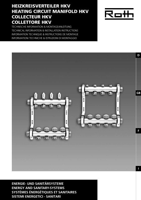
<strong>Heizkreisverteiler</strong> HKV<br />
<strong>Heating</strong> <strong>circuit</strong> <strong>manifold</strong> HKV<br />
COLLECTEUR HKV<br />
Collettore HKV<br />
Technische Information & MontageANLEITUNG<br />
Technical Information & Installation INSTRUCTIONS<br />
Information technique & INSTRUCTIONS DE Montage<br />
Informationi Techniche & ISTRUZIONI DI Montaggio<br />
D<br />
GB<br />
F<br />
I<br />
ENERGIE- UND SANITÄRSYSTEME<br />
ENERGY AND Sanitary-SYSTEMS<br />
Systèmes énergétiques et sanitaires<br />
SISTEMI ENERGETICI - SANITARI
Inhaltsübersicht / Summary /<br />
Table des matières / Sommario<br />
D<br />
Deutsch<br />
Beschreibung.. . . . . . . . . . . . . . . . . . . . . . . . . 4<br />
Technische Daten.. . . . . . . . . . . . . . . . . . . . . . 4<br />
Abmessungen .. . . . . . . . . . . . . . . . . . . . . . . . 5<br />
Montage. . . . . . . . . . . . . . . . . . . . . . . . . . . . . 6<br />
Befüllung / Druckprotokoll.. . . . . . . . . . . . . . 7<br />
Durchflussmenge/ Heizkreis.. . . . . . . . . . . 8-9<br />
Zubehör .. . . . . . . . . . . . . . . . . . . . . . . . . . . . 10<br />
francais<br />
Description.. . . . . . . . . . . . . . . . . . . . . . . . . . 20<br />
Données techniques.. . . . . . . . . . . . . . . . . . 20<br />
Dimensions. . . . . . . . . . . . . . . . . . . . . . . . . . 21<br />
Installation.. . . . . . . . . . . . . . . . . . . . . . . . . . 22<br />
Remplissage / Tests de pression.. . . . . . . . . 23<br />
Débitmètre / Circuit.. . . . . . . . . . . . . . . . 24-25<br />
Accessoires.. . . . . . . . . . . . . . . . . . . . . . . . . . 26<br />
Bitte beachten!<br />
Attention!<br />
GB<br />
Verweis auf andere Abschnitte in der<br />
Bedienungsanleitung.<br />
Verweis auf andere Montageanleitungen.<br />
Référence à d’autres sections du mode<br />
d’emploi.<br />
Référence à d’autres modes d’emploi.<br />
F<br />
english<br />
Description.. . . . . . . . . . . . . . . . . . . . . . . . . . 12<br />
Technical data. . . . . . . . . . . . . . . . . . . . . . . . 12<br />
Dimensions.. . . . . . . . . . . . . . . . . . . . . . . . . . 13<br />
Installation.. . . . . . . . . . . . . . . . . . . . . . . . . . 14<br />
Filling / Pressure test. . . . . . . . . . . . . . . . . . . 15<br />
Flowmeter / Circuit.. . . . . . . . . . . . . . . . . 16-17<br />
Accessories.. . . . . . . . . . . . . . . . . . . . . . . . . . . . . . 18<br />
Italiano<br />
Descrizione.. . . . . . . . . . . . . . . . . . . . . . . . . . 28<br />
Dati tecnici.. . . . . . . . . . . . . . . . . . . . . . . . . . 28<br />
Dimensioni.. . . . . . . . . . . . . . . . . . . . . . . . . . 29<br />
Montaggio.. . . . . . . . . . . . . . . . . . . . . . . . . . 30<br />
Riempimento / Test di pressione.. . . . . . . . . 31<br />
Portata / Circuito di riscaldamento.. . . . 32-33<br />
Accessori.. . . . . . . . . . . . . . . . . . . . . . . . . . . . 34<br />
Take note!<br />
Attenzione!<br />
I<br />
Reference to other sections in this<br />
instruction.<br />
Reference to other installation instruction.<br />
Note nelle altre sezioni di queste<br />
istruzioni.<br />
Note nelle altre istruzioni di installazione.<br />
2
<strong>Heizkreisverteiler</strong> HKV<br />
Technische Information & MontageANLEITUNG<br />
Deutsch<br />
D<br />
GB<br />
F<br />
I
Technische Daten<br />
Beschreibung<br />
Die <strong>Roth</strong> <strong>Heizkreisverteiler</strong> bestehen aus korrosionsbeständigem<br />
Rohr und sind für den Einsatz in<br />
Flächen-Heiz- und Kühlsystemen ausgelegt.<br />
Vorlauf und Rücklauf sind schallentkoppelt auf<br />
Verteilerhaltern vormontiert.<br />
D<br />
Technische Daten HKV Universal HKV mit DFA<br />
Material<br />
Messing<br />
GB<br />
Anzahl Heizkreise 2 – 12<br />
Mittenabstand<br />
54 mm<br />
Anschluss Systemrohre<br />
Anschluss VL / RL<br />
Max. Druck<br />
¾" Eurokonus<br />
1" AG flachdichtend<br />
6 bar<br />
Max. Temperatur 70 °C<br />
Anschlussgewinde Ventil M 30 × 1,5<br />
Ventilhub<br />
3 mm<br />
Max. Durchfluss / Heizkreis<br />
4 l/min<br />
F<br />
Einstellung<br />
Durchflussmenge<br />
Mit Regulierverschraubung<br />
gemäß Diagramm, Seite 9<br />
Mit einstellbarem Ventil,<br />
ablesbar im Schauglas,<br />
DFA maximal geöffnet<br />
I<br />
4
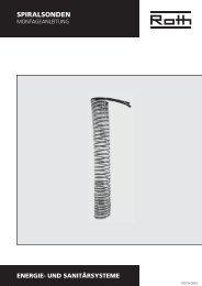
Abmessungen<br />
Abmessungen<br />
mit DFA<br />
universal<br />
D<br />
GB<br />
1<br />
2<br />
Vorlauf (montiert mit Durchflussanzeigen<br />
oder Regulierverschraubung und Anschlussnippeln)<br />
Rücklauf (montiert mit Ventileinsatz und<br />
Anschlussnippeln)<br />
3 Regulierverschraubung<br />
4 Durchflussanzeige (DFA)<br />
5 Anschlussnippel<br />
6 Anschlussnippel DFA<br />
7 Bauschutzkappe<br />
8 Ventileinsatz für Stellantrieb<br />
9 Verteilerhalter<br />
10 Stellantrieb (nicht im Lieferumfang enthalten)<br />
F<br />
Größe 2 3 4 5 6 7 8 9 10 11 12<br />
L (mm) 189 243 297 351 405 459 513 567 621 675 729<br />
Mit Endstücken 249 303 357 411 465 519 573 627 681 735 789<br />
I<br />
5
Montage<br />
Lieferumfang<br />
HKV mit Vorlauf und Rücklauf auf Verteilerhaltern<br />
mit integrierter Schallentkopplung vormontiert.<br />
Verteilerendstücke (Befüllen, Entlüften, Absperren)<br />
beigelegt.<br />
Drucksachen beigelegt.<br />
Regulierverschraubung Durchfluss und Ventil maximal<br />
geöffnet.<br />
D<br />
Montage<br />
• Im Aufputz/Unterputz Verteilerschrank<br />
• Wandmontage (Schallentkopplung bauseits)<br />
GB<br />
Schrankbreite<br />
Anzahl Heizkreise (Größe) HKV<br />
0 560 mm 4 3 2 - - -<br />
I 700 mm 7 6 4 3 2 -<br />
II 900 mm 11 10 7 7 6 4<br />
III 1.100 mm 12 12 12 11 11 8<br />
IV 1.300 mm 12 12 12 12 12 12<br />
0 550 mm 4 3 2 - - -<br />
I 750 mm 8 7 5 4 3 -<br />
II 950 mm 12 11 8 8 7 5<br />
III 1.150 mm 12 12 12 12 12 9<br />
F<br />
Anschluss Vorlauf<br />
und Rücklauf<br />
• Anschließen von Vorlauf und Rücklauf<br />
• Anschließen der Heizkreise mit Klemmverschraubung<br />
oder Pressverschraubung<br />
¾" Eurokonus<br />
I<br />
Klemmverschraubung Ø 11, 14, 16, 17, 20 Pressverschraubung Ø 14, 16, 17, 20<br />
6
Befüllen / Druckprotokoll<br />
Befüllung<br />
D<br />
GB<br />
1 Bauschutzkappe lösen, DFA oder Regulierverschraubung<br />
öffnen<br />
2 Befüllen (Heizkreis für Heizkreis) über den Vorlauf<br />
3 Bauschutzkappe wieder aufsetzen und Ventil<br />
schließen<br />
Alle weiteren Heizkreise genauso befüllen.<br />
4 Nach dem Befüllen aller Heizkreise die Kugelhähne<br />
am Endstück schließen<br />
Druckprotokoll<br />
Druckprotokoll<br />
F<br />
Druckprobe: Dauer vor und<br />
während der Estrichverlegung<br />
Prüfdruck min 6 bar oder<br />
2 × Betriebsdruck<br />
I<br />
7
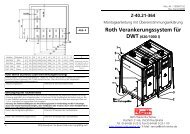
Durchflussmenge / Heizkreis<br />
HKV mit Durchflussanzeige<br />
Die Durchflussanzeige dient nur zur<br />
Absperrung der Heizkreise.<br />
2<br />
1 Bauschutzkappe am 1. Heizkreis entfernen<br />
2 DFA ganz öffnen<br />
3 Durchfluss gemäß Auslegung am Ventil<br />
einstellen<br />
D<br />
Alle weiteren Heizkreise genauso einstellen.<br />
4 Stellantriebe gemäß Montageanleitung<br />
montieren und anschließen<br />
3<br />
4<br />
1<br />
GB<br />
Druckverlust HKV<br />
1" mit DFA<br />
1 bis 12 Anschlüsse<br />
F<br />
Dp [mbar]<br />
I<br />
[l/min]<br />
8
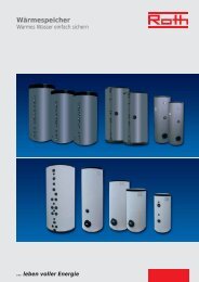
Durchflussmenge / Heizkreis<br />
3<br />
2<br />
4<br />
Alle Regulierverschraubungen und Ventile<br />
müssen geschlossen sein.<br />
HKV mit Regulierverschraubung<br />
1 Bauschutzkappe am 1. Heizkreis entfernen<br />
2 M5 Schraube der Regulierverschraubung<br />
lösen<br />
3 Mit M4 Schlüssel den Durchfluss an der<br />
Regulierverschraubung gemäß Auslegung<br />
oder Diagramm einstellen<br />
4 Mit M5 Schlüssel die Einstellung an der<br />
Regulierverschraubung sichern<br />
5<br />
D<br />
1<br />
Alle weiteren Heizkreise genauso einstellen.<br />
5 Stellantriebe gemäß Montageanleitung<br />
montieren und anschließen<br />
Druckverlust Regulierverschraubung<br />
GB<br />
Umdrehungen von<br />
geschlossen bis<br />
maximal geöffnet<br />
[l/min]<br />
F<br />
I<br />
Dp [mbar]<br />
9
Zubehör<br />
Zubehör<br />
D<br />
Klemmverschraubungen Ø 11, 14, 16, 17, 20 Pressverschraubungen Ø 14, 16, 17, 20<br />
Kugelhahn 1" Blindkappe ¾"<br />
GB<br />
Wärmemengenzähler-Set senkrecht<br />
Wärmemengenzähler-Einbauset waagerecht<br />
F<br />
Festwertregelsets, Regelstation<br />
Verteilerschränke: Größe 0, I, II, III, auf Putz IV<br />
I<br />
Stellantrieb 230 V, 24 V<br />
10
<strong>Heating</strong> <strong>circuit</strong> <strong>manifold</strong> HKV<br />
Technical Information &<br />
Installation Instructions<br />
English<br />
D<br />
GB<br />
F<br />
I
Technical data<br />
Description<br />
The <strong>Roth</strong> <strong>manifold</strong> consists of corrosion-resistant<br />
pipe and is designed for the use in surface embedded<br />
heating and cooling systems.<br />
Supply and return are mounted on sound-insulated<br />
brackets.<br />
D<br />
Technical data HKV Universal HKV with flowmeter<br />
Material<br />
Brass<br />
GB<br />
Number of <strong>circuit</strong>s 2 – 12<br />
Distance between pipes<br />
54 mm<br />
Connection of systempipes<br />
Connection VL / RL<br />
Max. pressure<br />
¾" Eurocone<br />
1" (male) flatsealed<br />
6 bar<br />
Max. temperature 70 °C<br />
Connection actuating valve M 30 × 1,5<br />
Valve lift<br />
Max. flow / <strong>circuit</strong><br />
3 mm<br />
4 l/min<br />
F<br />
Adjustment of the flow<br />
Adjustable screw fittings<br />
according to diagram, Page 17<br />
Adjustable valve in the return,<br />
flow indicators in the supply<br />
max. open<br />
I<br />
12
Dimensions<br />
Dimensions<br />
with flowmeter<br />
universal<br />
D<br />
GB<br />
1<br />
2<br />
Supply (mounted with flowmeters or adjustable<br />
screw fittings and pipe-connecting<br />
fittings)<br />
Return (mounted with valve and pipe<br />
connecting fittings)<br />
3 Adjustable screw fitting<br />
4 Flowmeter (DFA)<br />
5 Pipe connecting fitting<br />
6 Pipe connecting nipple DFA<br />
7 Protecting cap<br />
8 Valve for actuating drive<br />
9 Manifold bracket<br />
10 Actuating drive (to be ordered separately)<br />
F<br />
Size 2 3 4 5 6 7 8 9 10 11 12<br />
L (mm) 189 243 297 351 405 459 513 567 621 675 729<br />
With endpieces 249 303 357 411 465 519 573 627 681 735 789<br />
I<br />
13
Installation<br />
Scope of delivery<br />
Manifold supply and return mounted on brackets<br />
end pieces for filling manual ventilation, draining<br />
with ball valves and instruction manual and identifying<br />
labels for rooms and <strong>circuit</strong>s adjustable screw<br />
fitting flowmeter and valve maximum opened.<br />
D<br />
Installation<br />
• In in-wall or on-wall cabinet<br />
• Directly on the wall (sound protection not<br />
included)<br />
GB<br />
Cabinet width<br />
Number of <strong>circuit</strong>s (Size)<br />
0 560 mm 4 3 2 - - -<br />
I 700 mm 7 6 4 3 2 -<br />
II 900 mm 11 10 7 7 6 4<br />
III 1.100 mm 12 12 12 11 11 8<br />
IV 1.300 mm 12 12 12 12 12 12<br />
0 550 mm 4 3 2 - - -<br />
I 750 mm 8 7 5 4 3 -<br />
II 950 mm 12 11 8 8 7 5<br />
III 1.150 mm 12 12 12 12 12 9<br />
F<br />
Connection of the<br />
heating and cooling<br />
<strong>circuit</strong>s<br />
• Connection of main supply and return<br />
1" (male) flat sealed<br />
• Connection of the heating/cooling <strong>circuit</strong>s<br />
with compression fittings or press connections<br />
¾" euro cone<br />
I<br />
Compression fittings Ø 11, 14, 16, 17, 20 Press connection Ø 14, 16, 17, 20<br />
14
Filling / Pressure test<br />
Filling<br />
D<br />
GB<br />
1 Remove protection cap, open flowmeter DFA<br />
or adjustable screw fitting<br />
2 Fill always via supply (<strong>circuit</strong> by <strong>circuit</strong>)<br />
3 Close protection cap<br />
Repeat step 1 to 3 for all <strong>circuit</strong>s.<br />
4 After filling all the <strong>circuit</strong>s, close the ball valves of<br />
the end pieces<br />
Pressure test<br />
Pressure test<br />
F<br />
Leakage test: pressure test before<br />
and while bringing in the screed<br />
Test pressure min 6 bar or<br />
2 × operating pressure<br />
I<br />
15
Flowmeter / Circuit<br />
Manifold HKV with<br />
flowmeter DFA<br />
The flowmeter is only used for shutting<br />
the <strong>circuit</strong>s!<br />
2<br />
1 Remove the protection cap from the 1st<br />
<strong>circuit</strong>’s valve<br />
2 Open the flowmeter completely<br />
D<br />
3 Adjust the flow according to the calculation<br />
on the valve<br />
Repeat step 1 to 3 for each <strong>circuit</strong>.<br />
4<br />
1<br />
4 Install and connect the actuating drives<br />
according to the manual<br />
3<br />
GB<br />
Loss of pressure<br />
<strong>manifold</strong> HKV with<br />
flowmeter<br />
1 to 12 <strong>circuit</strong>s<br />
F<br />
Dp [mbar]<br />
I<br />
[l/min]<br />
16
Flowmeter / Circuit<br />
3<br />
2<br />
4<br />
All adjustable screw fittings and valves<br />
must be closed!<br />
Manifold HKV with<br />
adjustable screw<br />
fittings<br />
1 Remove the protection cap from the<br />
1st <strong>circuit</strong>’s valve<br />
2 Disconnect M5 screw<br />
5<br />
3 Adjust the flow with M4 allen key<br />
according to the calculation or diagram<br />
D<br />
1<br />
4 Fix the adjustment with M5 allen key<br />
Repeat step 1 to 4 for each <strong>circuit</strong>.<br />
5 Install and connect the actuators according<br />
to the manual<br />
Loss of pressure<br />
of adjustable screw<br />
fitting<br />
GB<br />
Turns from closed<br />
to maximum open<br />
[l/min]<br />
F<br />
I<br />
Dp [mbar]<br />
17
Accessories<br />
Accessories<br />
D<br />
Compression fittings Ø 11, 14, 16, 17, 20 Press connections Ø 14, 16, 17, 20<br />
Ballvalve 1" Screw cap ¾"<br />
GB<br />
Heat meter WMZ vertical<br />
Heat meter WMZ horizontal<br />
F<br />
Fix-value control sets, control station<br />
Cabinet: Dimension 0, I, II, III, surface mounting IV<br />
I<br />
Actuator 230 V, 24 V<br />
18
COLLECTEUR HKV<br />
Information Technique &<br />
InstructionS de Montage<br />
Francais<br />
D<br />
GB<br />
F<br />
I
Données techniques<br />
Description<br />
Les distributeurs de <strong>circuit</strong> de chauffage se composent<br />
de tubes résistants à la corrosion, et conviennent<br />
parfaitement aux systèmes de chauffage et<br />
rafraîchissement au sol.<br />
L’aller et le retour sont pré-montés sur des supports<br />
isolés phoniquement.<br />
Données<br />
techniques<br />
Collecteur HKV Universel<br />
Collecteur HKV équipé<br />
d’un débitmètre<br />
D<br />
Matériaux<br />
Laiton<br />
Nombre de <strong>circuit</strong>s de chauffage 2 – 12<br />
GB<br />
Distance entre les tubes<br />
54 mm<br />
Raccordement des tubes Eurocônes ¾"<br />
Raccordement VL / RL<br />
Pression max.<br />
Fiche mâle 1" isolée<br />
6 bars<br />
Température max. 70 °C<br />
Soupape à fixer M 30 × 1,5<br />
Levée de soupape<br />
3 mm<br />
Flux max. / <strong>circuit</strong><br />
4 l/min<br />
F<br />
Réglage du flux<br />
A l’aide de la vis de réglage,<br />
selon le schéma, page 25<br />
Avec l’aide de la soupape réglable,<br />
visible au niveau de la jauge,<br />
indicateurs de flux ouverts au<br />
max.<br />
I<br />
20
Dimensions<br />
Dimensions<br />
avec débitmètre<br />
universel<br />
D<br />
GB<br />
1<br />
2<br />
Aller (équipées d’indicateurs de débit ou<br />
vis de réglage et systèmes de raccordement<br />
pour tubes)<br />
Retour (équipée de supports pour valves et<br />
tubes)<br />
3 Vis de réglage<br />
4 Débitmètre (DFA)<br />
5 Support de connexion pour tube<br />
6 Support de connexion pour tube DFA<br />
7 Bouchon de protection<br />
8 Valve pour le servomoteur<br />
9 Support pour le distributeur<br />
10 Servomoteur (non fourni)<br />
F<br />
Taille 2 3 4 5 6 7 8 9 10 11 12<br />
L (mm) 189 243 297 351 405 459 513 567 621 675 729<br />
Avec les<br />
extrémités<br />
249 303 357 411 465 519 573 627 681 735 789<br />
I<br />
21
Installation<br />
Pièces livrées<br />
Système de collecteur HKV avec aller / retour sur<br />
supports, équipé de dispositif d’isolation phonique<br />
intégré, embouts de distribution (remplissage,<br />
vidage, arrêt).<br />
Imprimés.<br />
Vis de réglage du débit et soupape ouverte au<br />
maximum.<br />
D<br />
Installation<br />
• Système mural/encastré<br />
• Montage au mur (protection phonique non fournie)<br />
GB<br />
Coffret largeur<br />
Nombre de <strong>circuit</strong>s de chauffage (Taille)<br />
0 560 mm 4 3 2 - - -<br />
I 700 mm 7 6 4 3 2 -<br />
II 900 mm 11 10 7 7 6 4<br />
III 1.100 mm 12 12 12 11 11 8<br />
IV 1.300 mm 12 12 12 12 12 12<br />
0 550 mm 4 3 2 - - -<br />
I 750 mm 8 7 5 4 3 -<br />
II 950 mm 12 11 8 8 7 5<br />
III 1.150 mm 12 12 12 12 12 9<br />
F<br />
Connexion aux<br />
<strong>circuit</strong>s de chauffage<br />
et refroidissement<br />
• Connexion au chauffage et refroidissement<br />
• Raccordement des <strong>circuit</strong>s de chauffage à l’aide<br />
de raccords à compression ou raccords à sertir<br />
Eurocône ¾"<br />
I<br />
Raccords à compression Ø 11, 14, 16, 17, 20 Raccords à sertir Ø 14, 16, 17, 20<br />
22
Remplissage / Test de pression<br />
Remplissage<br />
D<br />
GB<br />
1 Défaire le bouchon de protection, ouvrir le<br />
débitmètre ou la vis de réglage<br />
2 Remplir (<strong>circuit</strong> de chauffage) à l’aller<br />
3 Remettre le bouchon de protection<br />
Répéter les étapes 1 à 3 pour tous les autres <strong>circuit</strong>s.<br />
4 Après le remplissage des <strong>circuit</strong>s de chauffage,<br />
fermer les robinets au niveau des extrémités<br />
Test de pression<br />
Test de pression<br />
F<br />
Test de pression: avant et pendant<br />
les travaux de chape<br />
Pression de 6 bars min. ou<br />
2 × pression opérationnelle<br />
I<br />
23
Débitmètre / Circuit<br />
Système HKV avec<br />
débitmètre<br />
Le débitmètre ne sert qu’à fermer le <strong>circuit</strong><br />
de chauffage.<br />
2<br />
1 Retirer le bouchon de protection du<br />
<strong>circuit</strong> de chauffage 1<br />
2 Ouvrir entièrement le débitmètre<br />
3 Ajuster le flux selon le calcul sur la valve<br />
D<br />
Répéter les étapes 1 à 3 pour chaque <strong>circuit</strong>.<br />
4<br />
1<br />
4 Installer et raccorder les servomoteurs<br />
comme indiqué sur le manuel.<br />
3<br />
GB<br />
Perte de pression<br />
Collecteur HKV 1"<br />
avec débitmètre<br />
1 à 12 <strong>circuit</strong>s<br />
F<br />
Dp [mbar]<br />
I<br />
[l/min]<br />
24
Débitmètre / Circuit<br />
3<br />
2<br />
4<br />
Toutes les vis de réglage et soupapes<br />
doivent être fermées.<br />
Système HKV avec<br />
vis de réglage<br />
1 Retirer le bouchon de protection du<br />
premier <strong>circuit</strong> de chauffage<br />
2 Dévisser la vis M5<br />
5<br />
1<br />
3 Ajuster le niveau de flux avec la clef M4<br />
selon les calculs indiqués sur le schéma<br />
4 A l’aide de la clef M5, resserrer la vis de<br />
réglage<br />
D<br />
Répéter les étapes 1 à 4 pour chaque <strong>circuit</strong>.<br />
5 Installer et raccorder les servomoteurs<br />
selon le manuel<br />
Vis de réglage Perte<br />
de pression<br />
GB<br />
Tourner la vis pour<br />
qu’elle passe de<br />
la position fermée<br />
à entièrement<br />
ouverte<br />
[l/min]<br />
F<br />
I<br />
Dp [mbar]<br />
25
Accessoires<br />
Accessoires<br />
D<br />
Raccords à compression Ø 11, 14, 16, 17, 20 Raccords à sertir Ø 14, 16, 17, 20<br />
Vanne à sphère 1" Bouchon de protection ¾"<br />
GB<br />
Kit-Compteur de chaleur – vertical<br />
Kit-Compteur de chaleur – horizontal<br />
F<br />
Groupe hydrauliques, station de régulations<br />
Coffret: taille 0, I, II, III, mural IV<br />
I<br />
Servomoteur 230 V, 24 V<br />
26
Collettore HKV<br />
Informationi Techniche &<br />
Istruzioni di Montaggio<br />
Italiano<br />
D<br />
GB<br />
F<br />
I
Dati tecnici<br />
Descrizione<br />
Il collettore <strong>Roth</strong> è composto da un tubo resistente<br />
alla corrosione, che è rivestito per gli attacchi<br />
nell‘area del sistema di riscaldamento e raffrescamento.<br />
La mandata e il ritorno sono pre-montati ed isolati<br />
contro il rumore.<br />
Dati tecnici HKV Universale HKV con DFA<br />
D<br />
Materiale<br />
Ottone<br />
Numero di <strong>circuit</strong>i 2 – 12<br />
GB<br />
Distanza tra i tubi<br />
Attacchi del sistema<br />
Attacco VL / RL<br />
Pressione massima<br />
54 mm<br />
¾" Eurokono<br />
1" AG M<br />
6 bar<br />
Temperatura massima 70 °C<br />
Connessione valvola M 30 × 1,5<br />
Corsa valvola<br />
3 mm<br />
Max. flusso / <strong>circuit</strong>o<br />
4 l/min<br />
F<br />
Impostazione portata<br />
Con regolazione collegamento<br />
a vite. Seguire diagramma a<br />
pagina 33<br />
Con valvola regolabile valvola<br />
di ritorno, DFA aperto nella<br />
fornitura al massimo<br />
I<br />
28
Dimensioni<br />
Dimensioni<br />
con DFA<br />
universale<br />
D<br />
GB<br />
1<br />
Mandata (montata con segnalatore di portata<br />
o con regolatore ed attacco)<br />
2 Ritorno (montato con valvola ed attacco)<br />
3 Regolatore collegamento a vite<br />
4 Segnalatore di portata (DFA)<br />
5 Attacco raccordi<br />
6 Attacco raccordi DFA<br />
7 Cappuccio di protezione<br />
8 Valvola per attuatori<br />
9 Sostegno del collettore<br />
10 Attuatore (non compreso)<br />
F<br />
Tipo 2 3 4 5 6 7 8 9 10 11 12<br />
L (mm) 189 243 297 351 405 459 513 567 621 675 729<br />
Con tappo<br />
finale<br />
249 303 357 411 465 519 573 627 681 735 789<br />
I<br />
29
Montaggio<br />
Volume di consegna<br />
L‘HKV è pre-montato con la mandata e il ritorno<br />
al sostegno del collettore, con ventilatore manuale<br />
e bloccaggi inclusi, sono presenti le istruzioni, e i<br />
collegamenti a vite per la regolazione del flusso e<br />
delle valvole sono aperti al massimo.<br />
Montaggio<br />
• Cassetta collettore sopra/sotto intonaco<br />
• Montaggio al muro (aggancio in loco)<br />
D<br />
GB<br />
Cassette collettori<br />
largheza<br />
Numero di Circuiti (Tipo)<br />
0 560 mm 4 3 2 - - -<br />
I 700 mm 7 6 4 3 2 -<br />
II 900 mm 11 10 7 7 6 4<br />
III 1.100 mm 12 12 12 11 11 8<br />
IV 1.300 mm 12 12 12 12 12 12<br />
F<br />
0 550 mm 4 3 2 - - -<br />
I 750 mm 8 7 5 4 3 -<br />
II 950 mm 12 11 8 8 7 5<br />
III 1.150 mm 12 12 12 12 12 9<br />
Attacco mandata<br />
e ritorno<br />
• Installazione della mandata e del ritorno<br />
• Installazione del <strong>circuit</strong>o di riscaldamento con<br />
collegamento a vite a stringere o a stingere con<br />
bussola interna, ¾" Eurocono.<br />
I<br />
Collegamento a vite a stringere Ø 11, 14, 16, 17, 20<br />
Collegamento a vite a stringere con bussola interna<br />
Ø 14, 16, 17, 20<br />
30
Riempimento / Test di pressione<br />
Riempimento<br />
D<br />
GB<br />
1 Staccare il cappuccio di protezione, aprire o il<br />
DFA o il collegamento a vite del regolatore<br />
2 Riempire (<strong>circuit</strong>o di riscaldamento) sulla man<br />
data<br />
3 Riposizionare il cappuccio di protezione e chiudere<br />
la valvola<br />
Riempire gli altri <strong>circuit</strong>i di riscaldamento allo stesso<br />
modo<br />
4 Dopo aver riempito tutti i <strong>circuit</strong>i, chiudere i<br />
rubinetti a sfera e i terminali<br />
Test di pressione<br />
Test di pressione<br />
F<br />
Prova di pressione: durata e drenaggio<br />
Test di pressione min 6 bar o<br />
2 × pressione d‘esercizio<br />
I<br />
31
Portata / Circuito di riscaldamento<br />
HKV con indicatore<br />
flusso di portata<br />
DFA<br />
L‘indicatore di flusso di portata serve solo<br />
per la chiusura del <strong>circuit</strong>o di riscaldamento.<br />
1 Rimuovere il cappuccio di protezione al<br />
1. <strong>circuit</strong>o di riscaldamento<br />
2 Aprire tutto il DFA<br />
2<br />
D<br />
3 Regolare i flusso di portata alla valvola a<br />
seconda delle spiegazioni<br />
Regolare tutti gli altri allo stesso modo.<br />
4<br />
1<br />
4 Montare e chiudere gli attuatori a<br />
seconda delle istruzioni di montaggio<br />
3<br />
GB<br />
Perdita di pressione<br />
dell‘HKV 1"<br />
con DFA da 1 a 12<br />
attacchi<br />
F<br />
Dp [mbar]<br />
I<br />
[l/min]<br />
32
Portata / Circuito di riscaldamento<br />
3<br />
2<br />
4<br />
Tutti i collegamenti a vite e le valvole<br />
devono essere chiusi.<br />
1 Rimuovere il cappuccio di protezione al<br />
1. <strong>circuit</strong>o di riscaldamento<br />
2 Svitare la vite M5 del collegamento a<br />
vite regolato<br />
HKV con collegamento<br />
a vite<br />
regolato<br />
5<br />
1<br />
3 Con una chiave M4 regolare il flusso di<br />
portata del collegamento a vite secondo<br />
spiegazione o diagramma<br />
4 Con una chiave M5 assicurare<br />
l‘impostazione del collegamento<br />
D<br />
Tutti gli altri <strong>circuit</strong>i devono essere regolati allo<br />
stesso modo.<br />
5 Montare e raccordare gli attuatori<br />
secondo le istruzioni di montaggio<br />
Perdita di pressione<br />
del collegamento<br />
a vite<br />
GB<br />
Girare da chiuso a<br />
massimo aperto<br />
[l/min]<br />
F<br />
I<br />
Dp [mbar]<br />
33
Accessori<br />
Accessori<br />
D<br />
Collegamento a vite a stringere Ø 11, 14, 16, 17, 20<br />
Collegamento a vite a stringere con bussola interna<br />
Ø 14, 16, 17, 20<br />
Rubinetto a sfera 1" Tappo cieco ¾"<br />
GB<br />
Contatore quantità di calore-Kit verticale<br />
Contatore quantità di calore-Kit orizzontale<br />
F<br />
Kits di regolazione del valore fisso, stazione regulatrice<br />
Cassette collettori: dimensioni 0, I, II, III, sopra IV<br />
I<br />
Attuatore 230 V, 24 V<br />
34
Notizen / Notice / Notes / Note<br />
35
ROTH WERKE GMBH<br />
Am Seerain 2 • 35232 Dautphetal (Germany)<br />
Telefon +49 64 66/9 22-0 • Telefax +49 64 66/9 22-1 00<br />
Hotline +49 64 66/9 22-3 00<br />
E-Mail service@roth-werke.de • www.roth-werke.de<br />
Technische Änderungen vorbehalten. / Specifications subject to change. / Sous réserve de modifications techniques. / Con riserva di modifiche tecniche.