Neomat A 89.028 NS rev1 - Rollo Rieper
Neomat A 89.028 NS rev1 - Rollo Rieper
Neomat A 89.028 NS rev1 - Rollo Rieper

Create successful ePaper yourself
Turn your PDF publications into a flip-book with our unique Google optimized e-Paper software.
2.1.1) “Step-by-Step” Input:<br />
To control the automation in manual mode it is possible to connect<br />
a simple button (between the Common wire and the Step-by-Step<br />
input). The operating mode follows this sequence: up-stop-downstop.<br />
If the button is held down for more than 3 seconds (but less than 10),<br />
an UP movement is always activated (the one corresponding to key<br />
▲ on the radio controls). If the button is held down for more than 10<br />
seconds, a DOWN movement is always activated (corresponding to<br />
key ▼). This feature can be useful in order to “synchronise” multiple<br />
motors to the same operation regardless of their current status.<br />
GB<br />
2.1.2) “TTBUS” input:<br />
The “TTBUS” has been designed to control the control units of<br />
motors for shutters and rolling shutters. This Bus enables separate<br />
control of up to 100 control units by connecting them in parallel<br />
using only 2 conductors (Common and “TTBUS” wires). For further<br />
information see the operating instructions for the remote controls via<br />
“TTBUS”.<br />
2.1.3) Weather sensors:<br />
In the “Weather Sensor” input between the Common wire (black<br />
wire) and the Weather sensor input (orange wire) you can connect a<br />
simple wind sensor (anemometer) or a special wind-sun-rain sensor.<br />
Up to 5 control units can be connected in parallel to a single sensor.<br />
Be careful to observe the polarity of the signals (on all the motors,<br />
the black wire must be connected with the black, the orange with<br />
the orange).<br />
2.2) Connector and power supply cable (this section refers only to the NEOMAT A version and concerns customer service personnel<br />
only)<br />
! WARNING: if the power cord is damaged it must be replaced with an identical type supplied by the manufacturer or<br />
an authorised customer service centre.<br />
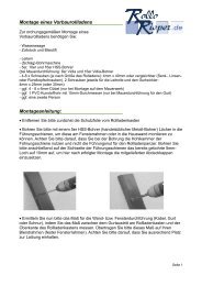
!If it is necessary to disconnect the motor from the power supply cable proceed as shown in the figures below:<br />
Rotate the ring nut until the notch<br />
matches one of the latch-on<br />
teeth, then release.<br />
Repeat the operation for the<br />
other tooth<br />
Bend the cable towards the inside<br />
and remove the protection by rotating<br />
it gently towards the outside<br />
Pull out the connector<br />
3) Adjustments<br />
The NEOMAT series tubular motors are equipped with an electronic<br />
limit switch system. The electronic control unit interrupts the movement<br />
when the shutter reaches the programmed open or closed<br />
positions. These positions must be programmed into the memory<br />
after the motor has been installed and the shutter has been fully<br />
mounted.<br />
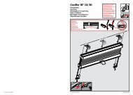
The motor can still be controlled even if these two positions, “0”<br />
(shutter open) and “1” (shutter close), have not yet been memorised;<br />
however, the movement in this case must be controlled manually. It<br />
is also possible to program an intermediate position (Pos. “I”) for partial<br />
opening of the shutter.<br />
Shutter open (Pos. “0”) Shutter close (Pos.”1”) Intermediate position (“I”)<br />
3