Neomat A 89.028 NS rev1 - Rollo Rieper
Neomat A 89.028 NS rev1 - Rollo Rieper
Neomat A 89.028 NS rev1 - Rollo Rieper

Create successful ePaper yourself
Turn your PDF publications into a flip-book with our unique Google optimized e-Paper software.
NEOMAT A is produced by Motus S.p.a. (TV) I. ERGO, PLANO, VOLO are produced by Nice S.p.a. (TV) I. Motus S.p.a. is an affiliate of the Nice S.p.a. group<br />
Warnings:<br />
The “NEOMAT A” series motors have been designed for the automation<br />
of roller shutters; any other use is considered improper and is prohibited.<br />
These motors are intended for residential use. Maximum continuous operating<br />
time is 4 minutes with a 20% cycle. When selecting the type of motor<br />
based on the application, you should consider the nominal torque and the<br />
operating time shown on the rating plate. The minimum diameter of the<br />
tube in which the motor can be installed is 40 mm for NEOMAT SA and<br />
70 mm for NOEMAT LA. The motor must be installed by qualified personnel<br />
in compliance with current safety regulations. As regards units for outdoor<br />
use, the PVC power supply cable must be installed inside a protective<br />
duct.<br />
The tubular motor must not be subjected to crushing, impacts, falls or<br />
contact with any kind of liquid. Do not perforate or drive screws into any<br />
part of the tubular motor (fig. 1). For maintenance and repairs contact a<br />
qualified technician.<br />
Warning: some programming phases may use the mechanical stops on<br />
the rolling shutter (rubber stops and/or anti-burglar latches). In such cases,<br />
the motor with the most suitable torque for a given application must be<br />
chosen, taking into consideration the effective weight of the rolling shutter<br />
in order to avoid choosing too powerful motors.<br />
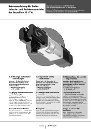
1) Product description<br />
The NEOMAT SA Ø35mm, NEOMAT MA Ø45mm (fig. 2) and NEO-<br />
MAT LA Ø58mm tubular motors feature an electronic control unit<br />
with incorporated radio receiver, operating at a frequency of 433.92<br />
MHz, with rolling code technology, to guarantee high levels of security.<br />
Up to 14 “ERGO” and “PLANO” or “VOLO S RADIO” series radio<br />
controls (fig. 3 and 4) can be memorised for each motor.<br />
The control unit incorporated in the motor features a high precision<br />
electronic limit switch system capable of continuously monitoring the<br />
position of the shutter. The range of movement, i.e. the closed/open<br />
positions (plus any intermediate positions) can be programmed and<br />
memorised; after each command, the movement stops automatically<br />
when these positions are reached.<br />
The control unit will also reveal any sharp variations and excessive<br />
strain on the motor, and quickly block the movement. This feature is<br />
also used to automatically programme the manoeuvring limits if the<br />
rolling shutter has upper limit switch rubber stops and anti-burglar<br />
latches.<br />
The range of movement and a few additional functions can be programmed<br />
through the radio controls. A beep will sound to guide the<br />
various phases. The motors can also be controlled through an external<br />
button (with step-by-step function) or a Bus (“TTBUS”). Optional<br />
wind, sun and rain sensors can activate the system automatically<br />
whenever the weather conditions demand it.<br />
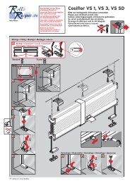
2) Installation<br />
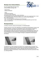
Proceed as follows to prepare the motor (fig. 4):<br />
1. Position the idle ring nut (E) on the motor (A) until it fits into the<br />
corresponding idle ring (F).<br />
2. Mount the draw ring nut (D) on the motor shaft. On NEOMAT SA<br />
the ring nut snaps on automatically.<br />
3. On NEOMAT MA, fasten the draw ring nut with the snap ring.<br />
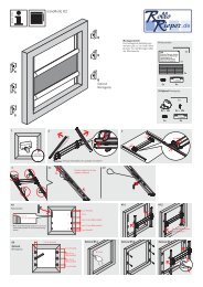
Figure 4<br />
A: NEOMAT tubular motor<br />
B: Fastening clips or split pins<br />
C: Support and spacer<br />
D: Draw ring nut<br />
E: Idle ring nut<br />
F: Idle ring<br />
Fit the assembled motor into the shutter’s winding tube until it touches<br />
the end of the idle ring nut (E). Fasten the tube to the draw ring<br />
nut (D) using the M4x10 screw in order to prevent the motor from<br />
slipping or sliding axially (fig. 5). Finally, secure the motor head to the<br />
special support (C) with the spacer (if any), using the clips or split pin<br />
(B).<br />
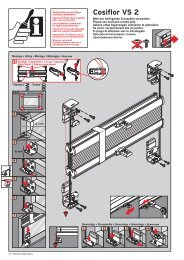
2.1) Electrical connections<br />
! WARNING: For motor connections, an omnipolar disconnecting<br />
device with a 3-mm minimum distance<br />
between contacts must be provided for disconnection<br />
from the mains power supply (disconnecting switch or<br />
plug and socket, etc.).<br />
! WARNING: carefully follow all the connection instructions.<br />
If you have any doubts do not make experiments but<br />
consult the relevant technical specifications sheets which<br />
are also available on the web site "www.niceforyou.com".<br />
Yellow label<br />
An incorrect connection may be dangerous and cause<br />
damage to the system.<br />
The cable used for the electrical connections of the NEOMAT A<br />
motor has 6 wires:<br />
• Supply line from the power mains: Phase, Neutral and Earth<br />
• Extra low voltage control signals (SELV): Step-by-step or<br />
“TTBUS” Bus and weather sensors<br />
Brown = Phase<br />
Blue = Neutral<br />
Yellow/Green = Earth<br />
Green label<br />
Black = Common (0V)<br />
White = Step-by-Step + “TTBUS”<br />
Orange = Weather sensorsi<br />
2