Neomat A 89.028 NS rev1 - Rollo Rieper
Neomat A 89.028 NS rev1 - Rollo Rieper
Neomat A 89.028 NS rev1 - Rollo Rieper

You also want an ePaper? Increase the reach of your titles
YUMPU automatically turns print PDFs into web optimized ePapers that Google loves.
tubular motor<br />
neomat A<br />
Instructions and warnings for the fitter<br />
Istruzioni ed avvertenze per l’installatore<br />
Instructions et recommandations pour l’installateur<br />
Anweisungen und Hinweise für den Installateur<br />
Instrucciones y advertencias para el instalador<br />
Instrukcje i uwagi dla instalatora
NEOMAT A is produced by Motus S.p.a. (TV) I. ERGO, PLANO, VOLO are produced by Nice S.p.a. (TV) I. Motus S.p.a. is an affiliate of the Nice S.p.a. group<br />
Warnings:<br />
The “NEOMAT A” series motors have been designed for the automation<br />
of roller shutters; any other use is considered improper and is prohibited.<br />
These motors are intended for residential use. Maximum continuous operating<br />
time is 4 minutes with a 20% cycle. When selecting the type of motor<br />
based on the application, you should consider the nominal torque and the<br />
operating time shown on the rating plate. The minimum diameter of the<br />
tube in which the motor can be installed is 40 mm for NEOMAT SA and<br />
70 mm for NOEMAT LA. The motor must be installed by qualified personnel<br />
in compliance with current safety regulations. As regards units for outdoor<br />
use, the PVC power supply cable must be installed inside a protective<br />
duct.<br />
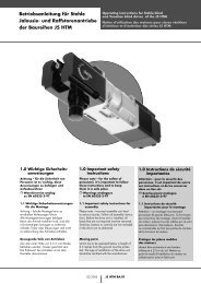
The tubular motor must not be subjected to crushing, impacts, falls or<br />
contact with any kind of liquid. Do not perforate or drive screws into any<br />
part of the tubular motor (fig. 1). For maintenance and repairs contact a<br />
qualified technician.<br />
Warning: some programming phases may use the mechanical stops on<br />
the rolling shutter (rubber stops and/or anti-burglar latches). In such cases,<br />
the motor with the most suitable torque for a given application must be<br />
chosen, taking into consideration the effective weight of the rolling shutter<br />
in order to avoid choosing too powerful motors.<br />
1) Product description<br />
The NEOMAT SA Ø35mm, NEOMAT MA Ø45mm (fig. 2) and NEO-<br />
MAT LA Ø58mm tubular motors feature an electronic control unit<br />
with incorporated radio receiver, operating at a frequency of 433.92<br />
MHz, with rolling code technology, to guarantee high levels of security.<br />
Up to 14 “ERGO” and “PLANO” or “VOLO S RADIO” series radio<br />
controls (fig. 3 and 4) can be memorised for each motor.<br />
The control unit incorporated in the motor features a high precision<br />
electronic limit switch system capable of continuously monitoring the<br />
position of the shutter. The range of movement, i.e. the closed/open<br />
positions (plus any intermediate positions) can be programmed and<br />
memorised; after each command, the movement stops automatically<br />
when these positions are reached.<br />
The control unit will also reveal any sharp variations and excessive<br />
strain on the motor, and quickly block the movement. This feature is<br />
also used to automatically programme the manoeuvring limits if the<br />
rolling shutter has upper limit switch rubber stops and anti-burglar<br />
latches.<br />
The range of movement and a few additional functions can be programmed<br />
through the radio controls. A beep will sound to guide the<br />
various phases. The motors can also be controlled through an external<br />
button (with step-by-step function) or a Bus (“TTBUS”). Optional<br />
wind, sun and rain sensors can activate the system automatically<br />
whenever the weather conditions demand it.<br />
2) Installation<br />
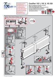
Proceed as follows to prepare the motor (fig. 4):<br />
1. Position the idle ring nut (E) on the motor (A) until it fits into the<br />
corresponding idle ring (F).<br />
2. Mount the draw ring nut (D) on the motor shaft. On NEOMAT SA<br />
the ring nut snaps on automatically.<br />
3. On NEOMAT MA, fasten the draw ring nut with the snap ring.<br />
Figure 4<br />
A: NEOMAT tubular motor<br />
B: Fastening clips or split pins<br />
C: Support and spacer<br />
D: Draw ring nut<br />
E: Idle ring nut<br />
F: Idle ring<br />
Fit the assembled motor into the shutter’s winding tube until it touches<br />
the end of the idle ring nut (E). Fasten the tube to the draw ring<br />
nut (D) using the M4x10 screw in order to prevent the motor from<br />
slipping or sliding axially (fig. 5). Finally, secure the motor head to the<br />
special support (C) with the spacer (if any), using the clips or split pin<br />
(B).<br />
2.1) Electrical connections<br />
! WARNING: For motor connections, an omnipolar disconnecting<br />
device with a 3-mm minimum distance<br />
between contacts must be provided for disconnection<br />
from the mains power supply (disconnecting switch or<br />
plug and socket, etc.).<br />
! WARNING: carefully follow all the connection instructions.<br />
If you have any doubts do not make experiments but<br />
consult the relevant technical specifications sheets which<br />
are also available on the web site "www.niceforyou.com".<br />
Yellow label<br />
An incorrect connection may be dangerous and cause<br />
damage to the system.<br />
The cable used for the electrical connections of the NEOMAT A<br />
motor has 6 wires:<br />
• Supply line from the power mains: Phase, Neutral and Earth<br />
• Extra low voltage control signals (SELV): Step-by-step or<br />
“TTBUS” Bus and weather sensors<br />
Brown = Phase<br />
Blue = Neutral<br />
Yellow/Green = Earth<br />
Green label<br />
Black = Common (0V)<br />
White = Step-by-Step + “TTBUS”<br />
Orange = Weather sensorsi<br />
2
2.1.1) “Step-by-Step” Input:<br />
To control the automation in manual mode it is possible to connect<br />
a simple button (between the Common wire and the Step-by-Step<br />
input). The operating mode follows this sequence: up-stop-downstop.<br />
If the button is held down for more than 3 seconds (but less than 10),<br />
an UP movement is always activated (the one corresponding to key<br />
▲ on the radio controls). If the button is held down for more than 10<br />
seconds, a DOWN movement is always activated (corresponding to<br />
key ▼). This feature can be useful in order to “synchronise” multiple<br />
motors to the same operation regardless of their current status.<br />
GB<br />
2.1.2) “TTBUS” input:<br />
The “TTBUS” has been designed to control the control units of<br />
motors for shutters and rolling shutters. This Bus enables separate<br />
control of up to 100 control units by connecting them in parallel<br />
using only 2 conductors (Common and “TTBUS” wires). For further<br />
information see the operating instructions for the remote controls via<br />
“TTBUS”.<br />
2.1.3) Weather sensors:<br />
In the “Weather Sensor” input between the Common wire (black<br />
wire) and the Weather sensor input (orange wire) you can connect a<br />
simple wind sensor (anemometer) or a special wind-sun-rain sensor.<br />
Up to 5 control units can be connected in parallel to a single sensor.<br />
Be careful to observe the polarity of the signals (on all the motors,<br />
the black wire must be connected with the black, the orange with<br />
the orange).<br />
2.2) Connector and power supply cable (this section refers only to the NEOMAT A version and concerns customer service personnel<br />
only)<br />
! WARNING: if the power cord is damaged it must be replaced with an identical type supplied by the manufacturer or<br />
an authorised customer service centre.<br />
!If it is necessary to disconnect the motor from the power supply cable proceed as shown in the figures below:<br />
Rotate the ring nut until the notch<br />
matches one of the latch-on<br />
teeth, then release.<br />
Repeat the operation for the<br />
other tooth<br />
Bend the cable towards the inside<br />
and remove the protection by rotating<br />
it gently towards the outside<br />
Pull out the connector<br />
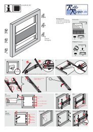
3) Adjustments<br />
The NEOMAT series tubular motors are equipped with an electronic<br />
limit switch system. The electronic control unit interrupts the movement<br />
when the shutter reaches the programmed open or closed<br />
positions. These positions must be programmed into the memory<br />
after the motor has been installed and the shutter has been fully<br />
mounted.<br />
The motor can still be controlled even if these two positions, “0”<br />
(shutter open) and “1” (shutter close), have not yet been memorised;<br />
however, the movement in this case must be controlled manually. It<br />
is also possible to program an intermediate position (Pos. “I”) for partial<br />
opening of the shutter.<br />
Shutter open (Pos. “0”) Shutter close (Pos.”1”) Intermediate position (“I”)<br />
3
4) Programming<br />
Programming is divided into three stages:<br />
1. Memorising the transmitters<br />
2. Programming the “0” and “1” positions<br />
3. Optional programming<br />
! WARNING: All the transmitter memorisation and parameter<br />
programming sequences are timed, i.e. they must<br />
be carried out within set time limits.<br />
• For radio controls designed to handle multiple “units”,<br />
before proceeding with the memorisation you need to<br />
select the unit to which the motor should be associated.<br />
• All the motors within the range of the transmitter can be<br />
programmed by radio; therefore, only the motor involved<br />
in the operation should be kept switched on.<br />
4.1) Memorizing the transmitters<br />
Each radio control is recognised by the receiver incorporated in the NEOMAT A control unit through an individual “code” that is unlike any<br />
other. The control unit must therefore be programmed to recognise each separate radio control through a “memorisation” process.<br />
When the memory does not contain any code, you can proceed to program the first radio control by operating as follows:<br />
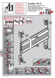
Table “A1” Memorising the first transmitter (fig. 7) Example<br />
1. When the control unit is switched on, you will hear two long beeps.<br />
2. Within 5 seconds, press and hold down (for approx. 3 seconds) key ■ on the transmitter<br />
that must be memorised<br />
3. When you hear the first of the 3 beeps confirming the memorisation, release key ■.<br />
3s<br />
Note: If the control unit already contains codes, 2 short beeps will be heard when it is switched on. In this case you cannot proceed as<br />
described above but must use the other memorisation method (Table “A2”).<br />
When one or more transmitters have already been memorised, additional ones can be enabled by proceeding as follows:<br />
Table “A2” Memorizing additional transmitters (fig 8) Example<br />
1. Press and hold down (approx. 5 seconds) key ■ on the new transmitter until you hear<br />
the beep. New 5s<br />
2. Slowly press key ■ on a previously enabled (old) transmitter 3 times<br />
Old<br />
X3<br />
3. Press again key ■ on the new transmitter.<br />
New<br />
4. Finally, 3 beeps will signal that the new transmitter has been correctly memorised.<br />
Note: If the memory is already full (14 codes), 6 beeps will indicate that the transmitter cannot be memorised.<br />
4.2) Programming the “0” and “1” positions<br />
Three basic situations may occur when using rolling shutter automations, ascribable to the presence, or lack, of those elements used to<br />
“block” the travel of the rolling shutter: limit switch “rubber stops” during ascent (which limit the maximum opening) and/or “anti-burglar latches”<br />
(which block the possibility to raise the rolling-shutter manually when it is completely closed).<br />
The limit-switches can be programmed differently depending on whether these mechanical stops (rubber stops and/or latches) are present<br />
or not:<br />
Manual programming of the limit-switches (no rubber stops or anti-burglar latches are required)<br />
Semi-automatic programming of the limit-switches (rubber stops are required during ascent)<br />
Automatic programming of the limit-switches (Both rubber stops during ascent, and anti-burglar latches during descent are required)<br />
To program the positions you need to use a previously memorised remote control. Unless the “0” and “1” positions have been memorised in<br />
the control unit, the movements require manual control. Initially the direction of the motor is not defined, but when programming has been<br />
executed, the direction of the motor will be automatically assigned to the remote control keys.<br />
4
Table “A3” MANUAL Programming the “0” and “1” positions (fig. 9) Example<br />
1. Press and hold down key ▲ or ▼ on a memorised remote control until the rolling<br />
shutter has reached the required opening position.<br />
2. Press and hold down key ■ on the transmitter until you hear a beep (approx. 5 seconds)<br />
3. Release and then press again key ■ for 5 more seconds until you hear 4 short beeps<br />
4. Press and hold down key ▲ until 3 beeps and a brief movement signal that the opening<br />
position has been memorised.<br />
5. Press and hold down key ▲ or ▼ on a memorised remote control until the rolling<br />
shutter has reached the required closing position.<br />
6. Press and hold down key ■ on the transmitter until you hear a beep (approx. 5 seconds)<br />
7. Release and then press again key ■ for 5 more seconds until you hear 4 short beeps<br />
8. Press key ▼ until 3 beeps and a brief movement signal that the closing “1” position has<br />
been memorised.<br />
N.B.: Key ▲ will now control upward movement while key ▼ the downward movement.<br />
The upward and downwards movements will stop at the programmed positions.<br />
5s<br />
5s<br />
5s<br />
5s<br />
GB<br />
Table “A4” SEMIAUTOMATIC Programming the “0” and “1” positions (fig. 10) Example<br />
1. Press and hold down key ▲ or ▼ on a memorised remote control until the rolling shutter has<br />
opened up completely and the motor stops automatically on the rubber stops.<br />
2. Press and hold down key ▼ to lower the shutter<br />
3. Release key ▼ when the shutter has reached the desired position (“1”)<br />
4. Press and hold down key ■ on the transmitter until you hear a beep (approx. 5 seconds)<br />
5. Release and then press again key ■ for 5 more seconds until you hear 4 short beeps<br />
6. Press and hold down key ▼ until 3 beeps and a brief movement signal that the closing “1”<br />
position has been memorised.<br />
N.B.: Key ▲ will now control the upward movement while key ▼ the downward movement.<br />
During ascent, the rolling shutter will stop in correspondence with the rubber stops, whilst during descent in correspondence with the<br />
programmed position.<br />
5s<br />
5s<br />
5s<br />
Table “A5” AUTOMATIC Programming the “0” and “1” positions (fig 11) Example<br />
1. Check that the rolling-shutter is at the mid travel stage, using the ▲ key or ▼ on a memorised<br />
remote control if necessary to move the rolling-shutter.<br />
2. Press the ■ key of a transmitter which has already been memorised, and keep it held down<br />
until you hear a beeping noise (this will happen after about 5 seconds). Then release the key.<br />
3. Press the ■ key down for a further 5 seconds until you hear 4 quick beeps, and then<br />
release the key.<br />
4. Press the ■ key once again and keep it held down until you hear the first of the two slow<br />
beeps.<br />
5. The rolling-shutter should move upwards, if it moves downwards, press the ▲ key or ▼ to<br />
make the rolling shutter move upwards.<br />
6. The procedure will continue automatically at this stage:<br />
first the system will find position “0” in correspondence with the opening rubber stops;<br />
following this position “1” in correspondence with the closing anti-burglar latches.<br />
7. The procedure is complete when the rolling-shutter is completely closed and 3 beeps<br />
have sounded.<br />
N.B.: Key ▲ will now control the upward movement, while key ▼ the downward movement.<br />
The upward and downward manoeuvres will stop just before the limits required.<br />
5s<br />
5s<br />
5
4.3) Optional programming<br />
Optional programming operations can only be performed after the “0” and “1” positions have been programmed<br />
Programming the intermediate position “I”<br />
If an intermediate position “I” has been memorised, the shutter can be moved to the programmed position by simultaneously pressing keys<br />
▼ and ▲ on the transmitter.<br />
To memorize the intermediate position proceed as follows:<br />
Table “A6” Programming the intermediate position “I” (fig 12) Example<br />
1. Using keys ▲ ■▼on a remote control, move the shutter to the position that you wish<br />
to memorise as “I”<br />
2. Press and hold down (approx. 5 seconds) key ■ until you hear the beep<br />
3. Release and then press again key ■ for 5 more seconds until you hear 4 short beeps<br />
4. Press keys ▼ and ▲ simultaneously until 3 beeps signal that the position has been<br />
memorised<br />
5s<br />
5s<br />
4.4) Modifying the memorised positions<br />
To modify the memorised positions, first you need to erase them, then you must reprogram the new positions.<br />
Table “A7” Erasing intermediate position “I” (fig 12) Example<br />
1. Press and hold down key ■ on a previously memorised transmitter until you hear a beep<br />
(approx. 5 seconds)<br />
2. Release and then press again key ■ for 5 more seconds until you hear 4 short beeps<br />
3. Press keys ▲ and ▼ simultaneously until 5 beeps signal that the intermediate position<br />
has been erased<br />
It will now be possible to programme the new intermediate position (Table “A6”)<br />
5s<br />
5s<br />
Table “A8” Erasing positions “0” and “1” (fig 13) Example<br />
1. Press and hold down key ■ on a previously memorised transmitter until you hear a beep<br />
(approx. 5 seconds)<br />
5s<br />
2. Release and then press again key ■ for 5 more seconds until you hear 4 short beeps<br />
5s<br />
3. Press either the ▲ key (if automatic or manual programming has been carried out) or the ▼<br />
key (if semiautomatic programming has been carried out), until you hear 5 beeps.<br />
This indicates that positions “0” and “1” have been deleted.<br />
WARNING: After positions “0” and “1” have been erased, the shutter will only move by manual control, therefore a new position must be<br />
memorised (Tables “A3”, “A4”, “A5”)<br />
If you need to erase all the data contained in the memory of the NEOMAT control unit, carry out the following procedure.<br />
The memory can be erased:<br />
• with a non-memorised transmitter starting from point A.<br />
• with a previously memorised transmitter starting the procedure from point N°1<br />
The following can be erased:<br />
• only the transmitter codes, finishing at point N°4<br />
• all the data (transmitter codes, positions, wind levels, TTBUS address, etc.), completing the procedure.<br />
Table “A9” Erasing the memory (fig 14) Example<br />
➨ A. Switch the motor off, activate the Step-by-Step input (by connecting up the white and black<br />
wires)and keep it active until the end of the procedure<br />
PP<br />
B. Power the motor and wait for the 2 initial beeps<br />
➨ 1. Press and hold down key ■ on a previously memorised transmitter until you hear a beep<br />
(approx. 5 seconds)<br />
2. Press and hold down key ▲ on the transmitter until you hear 3 beeps; release key ▲ exactly<br />
during the third beep.<br />
3. Press and hold down key ■ on the transmitter until you hear 3 beeps; release key ■ exactly<br />
during the third beep<br />
4. Press and hold down key ▼ on the transmitter until you hear 3 beeps; release key ▼ exactly<br />
during the third beep<br />
5. If you wish to erase all the data, press the ▲ and ▼ keys together within 2 seconds and then<br />
release them<br />
within 2s<br />
After a few seconds 5 beeps will signal that all the memorised codes have been erased.<br />
➨<br />
5s<br />
5s<br />
6
4.5) Programming the weather sensors<br />
If a wind sensor is connected to the “sensors” input, you can select the desired cut-in level from 3 possible levels (1= 15 Km/h, 2= 30 Km/h<br />
and 3= 45 Km/h if the “VOLO” sensor is used). The factory setting is N. 2. When this level is exceeded for over 3 seconds, a command corresponding<br />
to key ▲ is activated and all other movements are disabled until the wind speed returns below the programmed value for at least<br />
one minute.<br />
GB<br />
To modify the programmed level:<br />
Table “A10” Modifying the cut-in level of the “wind” protection (fig 15) Example<br />
1. Press key ■ on a previously memorised transmitter until you hear a beep<br />
(approximately 5 seconds)<br />
2. Press key ▲ slowly as many times (1, 2 or 3) as the number of the desired level<br />
3. After a few seconds you will hear a number of beeps corresponding to the required level<br />
4. Press key ■ to confirm; 3 beeps will confirm the new setting. To abort the procedure without<br />
modifying the previous level, wait at least 5 seconds without confirming<br />
5s<br />
X1= 15 km/h<br />
X2= 30 km/h<br />
X3= 45 km/h<br />
X1= 15 km/h<br />
X2= 30 km/h<br />
X3= 45 km/h<br />
4.6) Programming the positions without a transmitter<br />
Though it is not as easy, it is still possible to program the travel limits and positions “0” and “1” without using the remote control but only the<br />
step-by-step input<br />
Only the SEMI-AUTOMATIC or AUTOMATIC programming is available in this case.<br />
Table “A11” Programming positions “0” and “1” for SEMI-AUTOMATIC research Example<br />
1. Activate the step-by-step control; if the shutter moves down release the control and repeat<br />
the operation.<br />
2. Keep the step-by-step control active until the motor stops automatically because the<br />
completely open shutter has knocked against the rubber stops (position “0”).<br />
Then release the control<br />
3. Using the step-by-step control (manned control), stop the shutter during the down<br />
movement in the desired closed position (position “1”), so that a subsequent command<br />
will cause the shutter to move up<br />
4. Activate the step-by-step control 2 consecutive times (within 2 seconds) keeping the second<br />
command active for at least 5 seconds (motor off), until 3 beeps and a brief up and down<br />
movement signal that the position has been memorised<br />
PP<br />
PP<br />
PP<br />
PP<br />
X2(X5s)<br />
Table “A12” Programming positions “0” and “1” for AUTOMATIC research Example<br />
1. Activate the step-by-step control; if the shutter moves down release the control and repeat<br />
the operation.<br />
2. Keep the step-by-step control active until the motor stops automatically because the<br />
completely open shutter has knocked against the rubber stops (position “0”).<br />
3. Continue to keep the control active for another 5 seconds until you hear two beeps,<br />
then release the control.<br />
4. The rolling-shutter will start moving downwards “looking” for position “1”.<br />
This procedure can be interrupted by reactivating the step-by-step control.<br />
5. When the rolling-shutter is closed completely in correspondence with the anti-burglar latches,<br />
the rolling-shutter will stop and you will hear 3 beeps which indicate that positions “0” e “1”<br />
have been successfully programmed.<br />
Note: The partially open position cannot be memorised using the step-by-step control<br />
PP<br />
PP<br />
PP<br />
PP<br />
X5s<br />
If you wish to modify the positions you need to erase all the programmed settings and repeat the procedure from the beginning<br />
Table “A13” Erasing the positions “0” and “1” using the step-by-step control Example<br />
1. Activate the step-by-step control; if the shutter moves up release the control and repeat the<br />
operation.<br />
2. Keep the step-by-step control active until the shutter starts moving up after about 3 seconds;<br />
activate the step-by-step control 2 consecutive times (within 2 seconds), keeping the second<br />
command active to stop the shutter and then start moving it down.<br />
3. Repeat the previous step three more times.<br />
At the 3rd attempt the shutter will fail to move up.<br />
4. Continue to keep the step-by-step control active for another 10 seconds until 5 beeps signal<br />
that all the positions have been erased<br />
Note: After the positions have been erased, all the movements must be controlled manually<br />
PP<br />
PP<br />
PP<br />
PP<br />
PP<br />
PP<br />
3s<br />
3s<br />
X3<br />
7
5) What to do if… a small troubleshooting guide!<br />
When the motor is switched on, the 2 beeps do not sound<br />
and the Step-by-Step input does not control any movement.<br />
Make sure the motor is powered with the correct voltage; if the power<br />
input is correct there is probably a serious fault and the motor<br />
needs replacing.<br />
After a radio command, 6 beeps are heard and the<br />
manoeuvre does not start.<br />
The radio control unit is unsynchronised, repeat the transmitter<br />
memorisation process.<br />
After a command, 10 Beeps sound and then the manoeuvre<br />
begins.<br />
The auto-diagnosis of the memorised parameters has detected an<br />
abnormality (incorrect positions, TTBUS address, wind and sun levels,<br />
direction of movement). Check and repeat programming if necessary.<br />
After a command the motor does not turn.<br />
• The thermal protection might have triggered; in this case just wait<br />
for the motor to cool down<br />
• If a wind sensor has been connected, the set threshold might<br />
have been exceeded<br />
• You might try to switch the motor off and back on again; if the 2<br />
beeps do not sound, there is probably a serious fault and the<br />
motor needs replacing<br />
During the UP phase, before reaching the set position<br />
(pos. “0”, pos. “I”), the motor stops and then makes 3<br />
attempts to start up again. This does not necessarily mean trouble:<br />
if the programming of positions “0” ”1” was carried out SEMI-<br />
AUTOMATICALLY: when excessive strain is revealed during the<br />
upward movement, the motor will switch off for approximately 1 second,<br />
after which the system will attempt to complete the manoeuvre.<br />
Check for any obstacles which may be obstructing movement.<br />
The motor will stop before reaching the set position (pos.<br />
“0”, pos “I”, pos. “1”) during descent and ascent.<br />
This does not necessarily mean trouble: in case of overload the<br />
motor is switched off. Check to see if any obstacles are obstructing<br />
movement.<br />
The motor turns only if the control is manned.<br />
If positions “0” and “1” have not been programmed the motor rolls<br />
the shutter up or down only through manual control. Program positions<br />
“0” and “1”.<br />
Positions “0” and “1” have been programmed, but the<br />
shutter moves down only if the control is manned.<br />
The auto-diagnosis of the memorised parameters has detected an<br />
abnormality in the motor position. Give the command to raise the<br />
shutter and wait for it to reach position “0”<br />
6) Technical characteristics<br />
NEOMAT A series tubular motors<br />
Supply voltage and frequency<br />
: See the technical data on the label attached to each model<br />
Current and power<br />
: See the technical data on the label attached to each model<br />
Torque and speed<br />
: See the technical data on the label attached to each model<br />
Continuous operating time<br />
: Maximum 4 minutes<br />
Work cycle : Maximum 20%<br />
Protection class : IP 44<br />
Operating temperature : -10 ÷ 70 °C<br />
Precision (resolution) of the electronic limit switch : Greater than 0.55° (depending on the NEOMAT A version)<br />
Electronic control unit<br />
Signal voltage (step-by-step, sensors)<br />
Wind sensor (anemometer) levels<br />
Length of signal cables (step-by-step, sensors)<br />
Radio receiver<br />
Frequency<br />
Coding<br />
Range of ERGO and PLANO transmitters<br />
: Approx. 24Vdc<br />
: approx. 30 or 15 or 45 Km/h (with VOLO anemometer)<br />
: max. 30m if near other cables, otherwise 100m<br />
: 433.92 MHz<br />
: 52 Bit rolling code FLOR<br />
: Estimated 200 m in the open and 35 m inside buildings.<br />
Nice S.p.a. reserves the right to modify its products at any time without notice<br />
8
9<br />
GB
NEOMAT A è prodotto da Motus s.p.a. (TV) I. ERGO, PLANO, VOLO sono prodotti da Nice s.p.a.(TV) I. Motus s.p.a. è una società del gruppo Nice s.p.a.<br />
Avvertenze:<br />
I motori serie “NEOMAT A” sono stati realizzati per automatizzare il movimento<br />
di tapparelle; ogni altro uso è improprio e vietato. I motori sono progettati<br />
per uso residenziale; è previsto un tempo di lavoro continuo massimo<br />
di 4 minuti con un ciclo del 20%. Nella scelta del tipo di motore in<br />
funzione dell’applicazione, si dovrà considerare la coppia nominale ed il<br />
tempo di funzionamento riportati sui dati targa. Il diametro minimo del<br />
tubo in cui il motore può essere installato è 40mm per NEOMAT SA,<br />
52mm per NEOMAT MA e 70mm per NEOMAT LA. L’installazione deve<br />
essere eseguita da personale tecnico nel pieno rispetto delle norme di<br />
sicurezza. Negli apparecchi ad uso esterno, il cavo di alimentazione in<br />
PVC deve essere installato dentro un condotto di protezione.<br />
Non sottoporre il motore tubolare a schiacciamenti, urti, cadute o contatto<br />
con liquidi di qualunque natura; non forare né applicare viti per tutta la<br />
lunghezza del tubolare (fig. 1). Rivolgersi a personale tecnico competente<br />
per manutenzioni e riparazioni.<br />
Attenzione: alcune fasi della programmazione possono sfruttare i fermi<br />
meccanici della tapparella (tappi e/o molle anti-intrusione). In questo caso<br />
è indispensabile scegliere il motore con la coppia più adatta all’applicazione<br />
considerando l’effettivo peso della tapparella evitando motori troppo<br />
potenti.<br />
1) Descrizione del prodotto<br />
I motori tubolari NEOMAT SA Ø35mm, NEOMAT MA Ø45mm (fig.2)<br />
e NEOMAT LA Ø58mm contengono una centrale elettronica con<br />
ricevitore radio incorporato che opera alla frequenza di 433.92 MHz<br />
con tecnologia rolling code, per garantire elevati livelli di sicurezza.<br />
Per ogni motore è possibile memorizzare fino a 14 radiocomandi della<br />
serie “ERGO” e “PLANO” (fig.3) o “VOLO S RADIO”.<br />
La centrale incorporata nel motore dispone anche di un sistema di<br />
finecorsa elettronico ad elevata precisione che è in grado di rilevare<br />
costantemente la posizione della tapparella. Attraverso una operazione<br />
di programmazione vengono memorizzati i limiti del movimento,<br />
cioè tapparella chiusa e tapparella aperta (più una eventuale posizione<br />
intermedia); dopo ogni comando il movimento si fermerà automaticamente<br />
al raggiungimento di queste posizioni.<br />
La centrale riesce anche a rilevare brusche variazioni e sforzi del<br />
motore interrompendo prontamente il movimento, questa caratteristica<br />
è sfruttata anche per effettuare la programmazione automatica<br />
dei limiti di manovra se la tapparella dispone di tappi di finecorsa<br />
superiori e di molle anti-intrusione.<br />
La programmazione dei limiti di movimento e di alcune funzioni<br />
aggiuntive è eseguibile dai radiocomandi, un “Bip” acustico ne guiderà<br />
le varie fasi. E’ possibile comandare i motori anche con un pulsante<br />
esterno (con funzione passo-passo) oppure via Bus “TTBUS”.<br />
Eventuali sensori opzionali di vento, sole e pioggia possono attivare<br />
automaticamente il sistema quando le condizioni climatiche lo richiedono.<br />
2) Installazione<br />
Preparare il motore con la seguente sequenza di operazioni (fig. 5):<br />
1. Infilare la ghiera a folle (E) sul motore (A) fino ad inserirsi nel<br />
corrispondente anello a folle (F).<br />
2. Inserire la ghiera di trascinamento (D) sull’albero del motore.<br />
Su NEOMAT SA il fissaggio della ghiera è automatico a scatto<br />
3. Su NEOMAT MA, fissare la ghiera di trascinamento con il seeger<br />
a pressione<br />
Figura 4<br />
A: Motore tubolare NEOMAT A<br />
B: Fermagli o copiglie per fissaggio<br />
C: Supporto e distanziale<br />
D: Ghiera di trascinamento<br />
E: Ghiera a folle<br />
F: Anello a folle<br />
Introdurre il motore così assemblato nel tubo di avvolgimento della<br />
tapparella fino a toccare l’estremità della ghiera a folle (E). Fissare il<br />
tubo alla ghiera di trascinamento (D) mediante vite M4x10 in modo<br />
da evitare possibili slittamenti e spostamenti assiali del motore (fig.<br />
6). Infine bloccare la testa del motore all’apposito supporto (C), con<br />
l’eventuale distanziale mediante i fermagli o la copiglia (B).<br />
2.1) Collegamenti elettrici<br />
! ATTENZIONE: nei collegamenti del motore è necessario<br />
prevedere un dispositivo onnipolare di sconnessione<br />
dalla rete elettrica con distanza tra i contatti di almeno 3<br />
mm (sezionatore oppure spina e presa ecc.).<br />
! ATTENZIONE: rispettare scrupolosamente i collegamenti<br />
previsti; in caso di dubbio non tentare invano ma<br />
consultare le apposite schede tecniche di approfondimento<br />
disponibili anche sul sito "www.niceforyou.com".<br />
Un collegamento errato può provocare guasti o situazioni<br />
di pericolo.<br />
Il cavo per i collegamenti elettrici del motore NEOMAT A dispone di<br />
6 conduttori di collegamento:<br />
• Linea di alimentazione dalla rete elettrica: Fase, Neutro e Terra<br />
• Segnali di comando in bassissima tensione (SELV): Passo-Passo<br />
o Bus “TTBUS” e sensori climatici<br />
Etichetta<br />
gialla<br />
Marrone<br />
Blu<br />
Giallo/Verde<br />
= Fase<br />
= Neutro<br />
= Terra<br />
Etichetta<br />
verde<br />
Nero = Comune (0V)<br />
Bianco = Passo-P. + “TTBUS”<br />
Arancio = Sensori climatici<br />
10
2.1.1) Ingresso “Passo-Passo”:<br />
Per comandare l’automazione in modo manuale è possibile collegare<br />
un semplice pulsante (tra Comune e l’ingresso Passo-Passo).<br />
Il modo di funzionamento segue la sequenza: salita-stop-discesastop.<br />
Se il tasto viene mantenuto premuto per più di 3 secondi (ma<br />
meno di 10 ) si attiva sempre una manovra di salita (quella corrispondente<br />
al tasto ▲ dei radiocomandi).<br />
Se il tasto rimane premuto oltre i 10 secondi si attiva sempre una<br />
manovra di discesa (corrispondente al tasto ▼). Questa particolarità<br />
può essere utile per “sincronizzare” più motori verso la stessa manovra<br />
indipendentemente dallo stato in cui si trovavano.<br />
I<br />
2.1.2) Ingresso “TTBUS”:<br />
Il “TTBUS” è un Bus sviluppato per poter controllare le centrali di<br />
comando dei motori per tende e tapparelle. Il Bus prevede la possibilità<br />
di controllare singolarmente fino a 100 centrali collegandole<br />
semplicemente in parallelo con soli 2 conduttori (Comune e<br />
“TTBUS”). Ulteriori informazioni sono contenute nelle istruzioni nei<br />
telecomandi via “TTBUS”.<br />
2.1.3) Sensori climatici:<br />
Nell’ingresso “Sensori climatici” tra Comune (conduttore nero) e l’ingresso<br />
Sensori climatici (conduttore arancio) si può collegare un<br />
semplice sensore di vento (anemometro) oppure uno speciale sensore<br />
di vento-sole-pioggia.<br />
Ad uno stesso sensore si possono collegare fino a 5 centrali in parallelo<br />
rispettando la polarità dei segnali (su tutti i motori, il conduttore<br />
nero va collegato con il nero e l’arancio con l’arancio).<br />
2.2) Connettore e cavo di alimentazione (questo capitolo è relativo solo alla versione NEOMAT A ed è rivolto solo al personale<br />
tecnico dell’assistenza).<br />
! ATTENZIONE: se il cavo di alimentazione fosse danneggiato dovrà essere sostituito da uno identico disponibile presso<br />
il costruttore o il suo servizio di assistenza.<br />
Qualora sia necessario scollegare il motore dal cavo di alimentazione; agire come indicato nelle figure seguenti:<br />
Ruotare la ghiera fino a far coincidere<br />
lo smusso con uno dei denti<br />
di aggancio, quindi sganciare.<br />
Ripetere l’operazione per l’altro<br />
dente.<br />
Piegare il cavo verso l’interno e<br />
togliere la protezione ruotandola<br />
delicatamente verso l’esterno.<br />
Sfilare il connettore tirandolo<br />
3) Regolazioni<br />
I motori tubolari serie NEOMAT A dispongono di un sistema di fine<br />
corsa elettronico, la centrale elettronica interrompe il movimento<br />
quando la tapparella raggiunge le posizioni di chiusura e di apertura<br />
programmate. Queste posizioni vanno memorizzate con una opportuna<br />
programmazione che deve essere fatta direttamente con motore<br />
installato e tapparella completamente montata.<br />
Se le posizioni “0” (tapparella aperta) e “1” (tapparella chiusa) non<br />
sono ancora state memorizzate è possibile comandare ugualmente<br />
il motore ma il movimento avverrà a uomo presente. E’ possibile programmare<br />
anche una posizione intermedia (Pos. “I”) per una apertura<br />
parziale della tapparella.<br />
Tapparella aperta (Pos. “0”) Tapparella chiusa (Pos.”1”) Posizione intermedia (“I”)<br />
11
4) Programmazione<br />
La programmazione è divisa in 3 parti:<br />
1. Memorizzazione dei trasmettitori<br />
2. Programmazione delle posizioni “0” e “1”<br />
3. Programmazioni opzionali<br />
! ATTENZIONE: Tutte le sequenze di memorizzazione dei<br />
trasmettitori e delle programmazioni dei parametri sono a<br />
tempo, cioè devono essere eseguite entro i limiti di tempo<br />
previsti.<br />
• Con radiocomandi che prevedono più “gruppi”, prima di<br />
procedere alla memorizzazione occorre scegliere il<br />
gruppo al quale associare il motore.<br />
• La programmazione via radio può avvenire in tutti i<br />
motori che si trovano nel raggio della portata del trasmettitore;<br />
è quindi opportuno tenere alimentato solo<br />
quello interessato all’operazione.<br />
4.1) Memorizzazione dei trasmettitori<br />
Ogni radiocomando viene riconosciuto dalla ricevente incorporata nella centrale di NEOMAT A attraverso un “codice” diverso da ogni altro.<br />
E’ necessaria quindi una fase di “memorizzazione” attraverso la quale si predispone la centrale a riconoscere ogni singolo radiocomando.<br />
Quando la memoria non contiene nessun codice si può precedere all’inserimento del primo radiocomando con la seguente modalità:<br />
Tabella “A1” Memorizzazione del primo trasmettitore (fig 7) Esempio<br />
1. Appena data alimentazione alla centrale, si sentiranno 2 bip lunghi (biiip)<br />
2. Entro 5 secondi premere e tener premuto il tasto ■ del trasmettitore da memorizzare<br />
(per circa 3 secondi)<br />
3. Rilasciare il tasto ■ quando si sentirà il primo dei 3 bip che confermano la memorizzazione<br />
3s<br />
Nota: Se la centrale contiene già dei codici, all’accensione si udiranno 2 bip brevi (bip) e non si potrà procedere come<br />
descritto sopra ma occorre usare l’altra modalità di memorizzazione (Tabella “A2”)<br />
Quando uno o più trasmettitori sono già stati memorizzati, è possibile abilitarne altri in questo modo:<br />
Tabella “A2” Memorizzazione di altri trasmettitori (fig 8) Esempio<br />
1. Tenete premuto il tasto ■ del nuovo trasmettitore fino a sentire un bip (dopo circa 5 secondi)<br />
Nuovo<br />
2. Lentamente premere per 3 volte il tasto ■ di un trasmettere già abilitato (vecchio)<br />
Vecchio<br />
3. Premere ancora il tasto ■ del nuovo trasmettitore.<br />
Nuovo<br />
4. Alla fine 3 bip segnaleranno che il nuovo trasmettitore è stato memorizzato correttamente.<br />
5s<br />
X3<br />
Nota: Se la memoria è piena (14 codici), 6 Bip indicheranno il trasmettitore non può essere memorizzato.<br />
4.2) Programmazione delle posizioni “0” e “1”<br />
Nel caso di automazioni di tapparelle si possono presentare sostanzialmente 3 casi, questi sono riconducibili alla presenza o meno di elementi<br />
di “blocco” della corsa della tapparella: “tappi” di fine corsa in salita (che limitano l’apertura massima) e/o “molle anti-intrusione” (che<br />
impediscono di alzare manualmente la tapparella quando è completamente chiusa).<br />
A seconda della presenza o meno di questi limiti di corsa meccanici (tappi e/o molle) la programmazione dei fine corsa può essere fatta in<br />
maniera diversa:<br />
Programmazione manuale dei fine corsa (Non sono necessari tappi o molle anti-intrusione)<br />
Programmazione semiautomatica dei fine corsa (E’ necessaria la presenza dei tappi in salita)<br />
Programmazione automatica dei fine corsa (E’ necessaria sia la presenza dei tappi in salita che delle molle anti-intrusione in discesa)<br />
Per programmare le posizioni bisogna utilizzare un telecomando già memorizzato. Fino a quando nella centrale non vengono memorizzate<br />
le posizioni “0” e “1” valide, i movimenti sono a uomo presente. Inizialmente la direzione del motore non è definita, ma al completamento della<br />
programmazione la direzione del motore viene automaticamente assegnata ai tasti dei telecomandi.<br />
12
Tabella “A3” Programmazione MANUALE delle Posizioni “0” e “1” (fig 9) Esempio<br />
1. Premere e tenere premuto il tasto ▲ o il tasto ▼ di un telecomando memorizzato fino a<br />
portarsi nella posizione di apertura desiderata<br />
2. Tenere premuto il tasto ■ del trasmettitore fino a sentire un bip (dopo circa 5 secondi)<br />
3. Rilasciare e premere nuovamente per altri 5 secondi il tasto ■ fino a sentire 4 bip veloci<br />
4. Premere il tasto ▲ fino a quando 3 bip e un breve movimento segnalano che la posizione<br />
di apertura “0” è stata memorizzata<br />
5. Premere e tenere premuto il tasto ▲ o il tasto ▼ del telecomando memorizzato fino a<br />
portarsi nella posizione di chiusura desiderata<br />
6. Tenere premuto il tasto ■ del trasmettitore fino a sentire un bip (dopo circa 5 secondi)<br />
7. Rilasciare e premere nuovamente per altri 5 secondi il tasto ■ fino a sentire 4 bip veloci<br />
8. Premere il tasto ▼ fino a quando 3 bip e un breve movimento segnalano che la posizione di<br />
chiusura “1” è stata memorizzata<br />
Nota: Ora il tasto ▲ comanderà la manovra di salita mentre il tasto ▼ quella di discesa.<br />
La manovra in salita e quella in discesa si fermeranno in corrispondenza delle posizioni programmate.<br />
5s<br />
5s<br />
5s<br />
5s<br />
I<br />
Tabella “A4” Programmazione SEMIAUTOMATICA delle Posizioni “0” e “1”(fig 10) Esempio<br />
1. Premere e tenere premuto il tasto ▲ o il tasto ▼ di un telecomando memorizzato fino<br />
a quando si raggiunge l’apertura completa della tapparella e il motore si ferma<br />
automaticamente sui tappi in salita.<br />
2. Premere e tenere premuto il tasto ▼ che fa scendere la tapparella<br />
3. Rilasciare il tasto ▼ quando la tapparella raggiunge la posizione desiderata (“1”)<br />
4. Tenere premuto il tasto ■ del trasmettitore fino a sentire un bip (dopo circa 5 secondi)<br />
5. Rilasciare e premere nuovamente per altri 5 secondi il tasto ■ fino a sentire 4 bip veloci<br />
6. Premere il tasto ▼ fino a quando 3 bip e un breve movimento segnalano che la posizione<br />
di chiusura “1” è stata memorizzata<br />
Nota: Ora il tasto ▲ comanderà la manovra di salita mentre il tasto ▼ quella di discesa.<br />
In salita la tapparella si fermerà in corrispondenza dei tappi, in discesa in corrispondenza della posizione programmata.<br />
5s<br />
5s<br />
5s<br />
Tabella “A5” Programmazione AUTOMATICA delle Posizioni “0” e “1” (fig 11) Esempio<br />
1. Verificare che la tapparella sia a metà corsa circa, eventualmente utilizzare i tasti ▲ e ▼<br />
di un telecomando già memorizzato per spostare la tapparella a metà della corsa.<br />
2. Premere e tenere premuto il tasto ■ di un trasmettitore già memorizzato fino a sentire un<br />
bip (dopo circa 5 secondi) e rilasciare.<br />
3. Premere nuovamente per altri 5 secondi il tasto ■ fino a sentire 4 bip veloci e rilasciare.<br />
4. Premere nuovamente il tasto ■ fino a sentire il primo dei 2 bip lenti<br />
5. La tapparella dovrà muoversi verso l’alto, se il movimento è verso il basso bisogna premere<br />
il tasto ▲ o ▼ per per far muovere la tapparella verso l’alto<br />
6. La procedura a questo punto proseguirà automaticamente:<br />
prima verrà trovata la posizione “0” in corrispondenza dei tappi in apertura e<br />
successivamente la posizione “1” in corrispondenza delle molle anti-intrusione in chiusura.<br />
7. La procedura si concluderà con la tapparella completamente chiusa e con una<br />
segnalazione sonora di 3 bip<br />
Nota: Ora il tasto ▲ comanderà la manovra di salita mentre il tasto ▼ comanderà la manovra di discesa.<br />
La manovra in salita e quella in discesa si fermeranno poco prima dei limiti ricercati.<br />
5s<br />
5s<br />
13
4.3) Programmazioni opzionali<br />
Le programmazioni opzionali sono possibili solo dopo aver concluso le programmazioni delle posizioni “0” e “1”<br />
Memorizzazione della posizione intermedia “I”<br />
Se è memorizzata una posizione intermedia “I” è possibile muovere la tapparella nella posizione programmata premendo contemporaneamente<br />
i 2 tasti ▼▲ del trasmettitore.<br />
Per memorizzare la posizione intermedia seguire questa procedura:<br />
Tabella “A6” Programmazione posizione intermedia “I” (fig 12) Esempio<br />
1. Utilizzando i tasti ▲■▼di un telecomando portare la tapparella dove si desidera<br />
memorizzare la posizione “I”<br />
2. Tenere premuto il tasto ■ fino a sentire un bip (dopo circa 5 secondi)<br />
5s<br />
3. Rilasciare e premere nuovamente per altri 5 secondi il tasto ■ fino a sentire 4 bip veloci<br />
5s<br />
4. Premere contemporaneamente i tasti ▼ ▲ fino a quando 3 bip segnalano che la quota<br />
è stata memorizzata<br />
4.4) Modifica delle posizioni memorizzate<br />
Per modificare le posizioni memorizzate è necessario prima cancellarle e poi riprogrammare le nuove posizioni.<br />
Tabella “A7” Cancellazione della posizione intermedia “I” (fig 12) Esempio<br />
1. Tenere premuto il tasto ■ di un trasmettitore già memorizzato fino a sentire un bip<br />
(dopo circa 5 secondi)<br />
2. Rilasciare e premere nuovamente per altri 5 secondi il tasto ■ fino a sentire 4 bip veloci<br />
3. Premere contemporaneamente i tasti ▲ ▼ fino a quando 5 bip segnalano che la posizione<br />
intermedia è stata cancellata<br />
Ora sarà possibile programmare la nuova posizione intermedia (Tabella “A6”)<br />
5s<br />
5s<br />
Tabella “A8” Cancellazione posizioni “0” e “1” (fig 13) Esempio<br />
1. Tenere premuto il tasto ■ di un trasmettitore già memorizzato fino a sentire un bip<br />
(dopo circa 5 secondi)<br />
5s<br />
2. Rilasciare e premere nuovamente per altri 5 secondi il tasto ■ fino a sentire 4 bip veloci<br />
5s<br />
3. Premere il tasto ▲ (nel caso sia stata effettuata la programmazione automatica o manuale)<br />
o il tasto ▼ (nel caso di programmazione semiautomatica), fino a quando 5 bip segnalano<br />
che le posizioni “0” e “1” sono state cancellate<br />
ATTENZIONE: Dopo aver cancellato le posizioni “0” e “1” la tapparella si muoverà a uomo presente ed è necessario memorizzare le nuove<br />
posizioni (Tabelle “A3”, “A4”, “A5”)<br />
Se dovesse rendersi necessario cancellare tutti dati contenuti nella memoria della centrale di NEOMAT A, si può eseguire questa procedura.<br />
La cancellazione della memoria è possibile:<br />
• con un trasmettitore non memorizzato iniziando dal punto A.<br />
• con uno già memorizzato iniziando la procedura dal punto N°1<br />
Si possono cancellare:<br />
• solo i codici dei trasmettitori, terminando nel punto N°4<br />
• tutti i dati (codici dei trasmettitori, posizioni, livello del vento e sole, indirizzo TTBUS, ecc.) completando la procedura.<br />
Tabella “A9” Cancellazione della memoria (fig 14) Esempio<br />
➨ A. A motore non alimentato attivare l’ingresso passo-passo (collegare il filo bianco e nero)<br />
e mantenerlo attivo fino alla fine della procedura<br />
PP<br />
B. Alimentare il motore ed attendere i 2 bip iniziali.<br />
➨ 1. Tenere premuto il tasto ■ di un trasmettitore fino a sentire un bip<br />
(dopo circa 5 secondi).<br />
2. Tenere premuto il tasto ▲ del trasmettitore fino a sentire 3 bip; rilasciare il tasto ▲<br />
esattamente durante il terzo bip.<br />
3. Tenere premuto il tasto ■ del trasmettitore fino a sentire 3 bip; rilasciare il tasto ■<br />
esattamente durante il terzo bip.<br />
4. Tenere premuto il tasto ▼ del trasmettitore fino a sentire 3 bip; rilasciare il tasto ▼<br />
esattamente durante il terzo bip.<br />
5. Se si vogliono cancellare tutti i dati, entro 2 secondi, premere assieme i due tasti ▲ e ▼,<br />
poi rilasciarli.<br />
Dopo qualche secondo 5 bip segnalano che tutti i codici in memoria sono stati cancellati.<br />
➨<br />
entro 2s<br />
5s<br />
5s<br />
14
4.5) Programmazione sensori climatici<br />
Se all’ingresso “sensori” viene collegato un sensore di vento è possibile selezionare il livello di intervento tra 3 livelli possibili (1°= 15Km/h, 2°=<br />
30Km/h e 3°= 45 Km/h se utilizzato sensore “VOLO”), in origine il livello impostato è il N°2. Quando il livello viene superato per oltre 3 secondi,<br />
si attiva un comando equivalente al tasto ▲ e viene bloccato qualsiasi altro movimento fino a che il vento non ritorna sotto al livello programmato<br />
per almeno un minuto.<br />
Per modificare il livello programmato:<br />
Tabella “A10” Cambiare il livello di intervento della protezione “vento” (fig 15) Esempio<br />
1. Premere il tasto ■ di un trasmettitore già memorizzato fino a sentire un bip<br />
(dopo circa 5 secondi).<br />
2. Lentamente premere il tasto ▲ un numero di volte (1, 2 o 3) pari al livello desiderato.<br />
3. Dopo qualche istante si sentirà un numero di bip uguale al livello richiesto<br />
4. Premere il tasto ■ per confermare, 3 bip segnalano la nuova programmazione. Per abortire la<br />
procedura senza cambiare il livello precedente aspettare almeno 5 secondi senza confermare.<br />
5s<br />
X1= 15 km/h<br />
X2= 30 km/h<br />
X3= 45 km/h<br />
X1= 15 km/h<br />
X2= 30 km/h<br />
X3= 45 km/h<br />
I<br />
4.6) Programmazione delle posizioni senza trasmettitore<br />
Anche se in maniera meno agevole, è possibile programmare i limiti di corsa e le posizioni “0” e “1” senza telecomando, ma utilizzando solamente<br />
l’ingresso passo-passo.<br />
In questo caso sono possibili solo le programmazioni SEMIAUTOMATICA e AUTOMATICA.<br />
Tabella “A11” Programmazione posizioni “0” e “1” con ricerca SEMIAUTOMATICA Esempio<br />
1. Attivare il comando di passo-passo; se la tapparella si muove in discesa rilasciare il<br />
comando e ripetere l’operazione.<br />
2. Tenere attivo il comando di passo-passo fino a quando il motore si ferma automaticamente<br />
perché la tapparella completamente aperta ha urtato i tappi (posizione “0”).<br />
Poi rilasciare il comando<br />
3. Utilizzando il comando di passo passo (funzionamento a uomo presente) fermare, durante<br />
il movimento di discesa, la tapparella in corrispondenza del punto di chiusura desiderato<br />
(posizione “1”), in modo tale che un successivo comando provochi la salita della tapparella<br />
4. Attivare per 2 volte consecutive (entro 2 secondi) il passo passo mantenendo attivo il secondo<br />
comando per almeno 5 secondi (motore fermo), fino a quando 3 bip e un breve movimento<br />
di salita e discesa segnalano che la posizione è stata memorizzata<br />
PP<br />
PP<br />
PP<br />
PP<br />
X2(X5s)<br />
Tabella “A12” Programmazione posizioni “0” e “1” con ricerca in AUTOMATICO Esempio<br />
1. Attivare il comando di passo-passo; se la tapparella si muove in discesa rilasciare il<br />
comando e ripetere l’operazione.<br />
2. Tenere attivo il comando di passo-passo fino a quando il motore si ferma automaticamente<br />
perché la tenda è completamente avvolta (posizione “0”).<br />
3. Continuare a mantenere attivo il comando per altri 5 secondi fino a quando si sentono 2 bip,<br />
rilasciare il comando.<br />
4. La tapparella inizia a muoversi in discesa per ricercare la posizione “1”.<br />
La procedura può essere interrotta attivando nuovamente il comando di passo-passo<br />
5. Quando la tapparella raggiunge la completa chiusura in corrispondenza delle molle<br />
anti-intrusione, la tapparella si ferma e segnala con 3 bip l’avvenuta programmazione delle<br />
posizioni “0” e “1”<br />
Nota: Tramite comando di passo-passo non è possibile memorizzare la quota di apertura parziale.<br />
PP<br />
PP<br />
PP<br />
PP<br />
X5s<br />
Se si vogliono modificare le posizioni è necessario cancellare tutte le impostazioni eseguite e ripetere nuovamente tutta la procedura<br />
Tabella “A13” Cancellazione delle posizioni “0” e “1” tramite comando passo-passo Esempio<br />
1. Attivare il comando di passo-passo; se la tapparella si muove in salita rilasciare il comando<br />
e ripetere l’operazione.<br />
2. Mantenere attivo il comando fino a quando dopo circa 3 secondi parte una manovra di<br />
salita; attivare per 2 volte consecutive (entro 2 secondi) il passo passo, mantenendo attivo<br />
il 2° comando, per fermare e far ripartire in discesa la tapparella.<br />
3. Ripetere il punto precedente per altre 3 volte.<br />
Al 3° tentativo la manovra in salita non parte più.<br />
4. Continuare a mantenere attivo il comando di passo passo per altri 10 secondi fino a quando<br />
5 bip segnalano che tutte le posizioni sono state cancellate.<br />
Nota: Dopo la cancellazione delle posizioni i movimenti sono eseguiti a uomo presente<br />
PP<br />
PP<br />
PP<br />
PP<br />
PP<br />
PP<br />
3s<br />
3s<br />
X3<br />
15
5) Cosa fare se... cioè piccola guida se qualcosa non va!<br />
Dopo l’alimentazione il motore non emette i 2 Bip e l’ingresso<br />
Passo-Passo non comanda nessun movimento.<br />
Controllare che il motore sia alimentato alla tensione di rete prevista,<br />
se l’alimentazione è corretta è probabile vi sia un guasto grave ed il<br />
motore deve essere sostituito.<br />
Dopo un comando via radio si sentono 6 Bip e la manovra<br />
non parte.<br />
Il radiocomando e fuori sincronismo, bisogna ripetere la memorizzazione<br />
del trasmettitore.<br />
Dopo un comando si sentono 10 Bip poi parte la manovra.<br />
L’autodiagnosi dei parametri in memoria ha rilevato qualche anomalia<br />
(posizioni,indirizzo TTBUS, livello vento e sole, direzione del movimento<br />
sono errati) controllare ed eventualmente ripetere le programmazioni<br />
Dopo un comando il motore non si muove.<br />
• Potrebbe essere intervenuta la protezione termica, in questo caso<br />
basta aspettare che il motore si raffreddi.<br />
• Se è collegato un sensore di vento potrebbe essere superata la<br />
soglia impostata.<br />
• Altrimenti provare a spegnere e riaccendere il motore, se non si<br />
sentono 2 bip è probabile vi sia un guasto grave ed il motore deve<br />
essere sostituito.<br />
In salita, prima di raggiungere la posizione prevista (pos.<br />
“0”, pos. “I”), il motore si ferma e poi si sente che per 3<br />
tentativi cerca di ripartire.<br />
Può essere normale se si è eseguita la programmazione delle posizioni<br />
“0” ”1” in modalità SEMIAUTOMATICA: in salita quando viene<br />
rilevato uno sforzo eccessivo, il motore viene spento per circa 1<br />
secondo e poi si ritenta di portare a termine la manovra; verificare se<br />
ci sono ostacoli che impediscono il movimento.<br />
In discesa o in salita prima di raggiungere la posizione<br />
prevista (pos. “0”, pos “I”, pos. “1”), il motore si ferma.<br />
Può essere normale: quando viene rilevato uno sforzo eccessivo , il<br />
motore viene spento; verificare se ci sono ostacoli che impediscono<br />
il movimento<br />
Il motore si muove solo a “uomo presente”.<br />
Se le posizioni “0” e “1” non sono state programmate il movimento<br />
del motore in salita e in discesa avviene solo a uomo presente.<br />
Programmare le posizioni “0” e “1”<br />
La posizioni “0” e “1” sono programmate, ma in discesa si<br />
ha un movimento a uomo presente.<br />
L’autodiagnosi dei parametri in memoria ha rilevato una anomalia<br />
nella posizione del motore. Comandare la tenda in salita e attendere<br />
che raggiunga la posizione “0”<br />
6) Caratteristiche tecniche<br />
Motori tubolari serie NEOMAT A<br />
Tensione di alimentazione e frequenza<br />
: Vedere i dati tecnici sull’etichetta di ogni modello<br />
Corrente e potenza<br />
: Vedere i dati tecnici sull’etichetta di ogni modello<br />
Coppia e velocità<br />
: Vedere i dati tecnici sull’etichetta di ogni modello<br />
Tempo di funzionamento continuo<br />
: Massimo 4 minuti<br />
Ciclo di lavoro : Massimo 20%<br />
Grado di protezione : IP 44<br />
Temperatura di funzionamento : -10 ÷ 70 °C<br />
Precisione (risoluzione) del finecorsa elettronico : maggiore di 0,55° (dipende dalla versione del NEOMAT A)<br />
Centrale elettronica<br />
Tensione segnali (passo-passo, sensori)<br />
Livelli sensore vento (anemometro)<br />
Lunghezza cavi segnali (passo-passo, sensori)<br />
Ricevitore radio<br />
Frequenza<br />
Codifica<br />
Portata dei trasmettitori ERGO e PLANO<br />
: Circa 24Vdc<br />
: Circa 30 oppure 15 o 45 Km/h (con anemometro VOLO)<br />
: massimo 30m se in vicinanza ad altri cavi, altrimenti 100m<br />
: 433.92 MHz<br />
: 52 Bit rolling code FLOR<br />
: Stimata in 200 m se spazio libero e 35 m se all’interno di edifici.<br />
Nice S.p.a. si riserva il diritto di apportare modifiche ai prodotti in qualsiasi momento riterrà necessario.<br />
16
17<br />
I
NEOMAT A est produit par Motus S.p.a. (TV) I. ERGO, PLANO, VOLO sont produits par Nice S.p.a. (TV) I. Motus s.r.l. est une société du groupe Nice S.p.a.<br />
Avertissements:<br />
Les moteurs série “NEOMAT A” ont été réalisés pour automatiser le mouvement<br />
de volets roulants; toute autre utilisation est impropre et interdite.<br />
Les moteurs sont projetés pour usage résidentiel; le temps de travail<br />
continu maximum prévu est de 4 minutes avec un cycle de 20%. Dans le<br />
choix du type de moteur en fonction de l’application, il faudra considérer<br />
le couple nominal et le temps de fonctionnement indiqués sur les données<br />
de la plaque. Le diamètre minimum du tube dans lequel le moteur peut<br />
être installé est 40 mm pour NEOMAT SA, 52 mm pour NEOMAT MA et<br />
70 mm pour NEOMAT LA. L’installation doit être effectuée par du personnel<br />
technique dans le plein respect des normes de sécurité. Pour les<br />
appareils à utiliser à l’extérieur, le câble d’alimentation en PVC doit être<br />
installé dans un conduit de protection. Ne pas soumettre le moteur tubulaire<br />
à des écrasements, chocs, chutes ou contact avec des liquides de<br />
n’importe quelle nature ; ne pas percer ni appliquer de vis sur toute la longueur<br />
du moteur tubulaire (fig. 1). S’adresser à du personnel technique<br />
compétent pour toute opération de maintenance et réparation.<br />
Attention: certaines phases de la programmation peuvent utiliser les<br />
butées mécaniques du volet roulant (bouchons et/ou ressorts anti-intrusion).<br />
Dans ce cas, il est indispensable de choisir le moteur avec le couple<br />
le plus adapté à l’application en considérant le poids effectif du volet roulant<br />
et en excluant les moteurs trop puissants.<br />
1) Description du produit<br />
Les moteurs tubulaires NEOMAT SA Ø35 mm, NEOMAT MA Ø45 mm<br />
(fig. 2) et NEOMAT LA Ø58 mm contiennent une logique de commande<br />
avec récepteur radio incorporé qui fonctionne à une fréquence de<br />
433,92 MHz avec technologie rolling code, pour garantir des niveaux<br />
de sécurité élevés. Pour chaque moteur, il est possible de mémoriser<br />
jusqu’à 14 radiocommandes de la série “ERGO” et “PLANO” (fig. 3 et<br />
4) ou “VOLO S RADIO”. La logique incorporée dans le moteur dispose<br />
aussi d’un système de fin de course électronique à haute précision qui<br />
est en mesure de détecter constamment la position du volet roulant.<br />
À travers une opération de programmation, les limites du mouvement,<br />
à savoir volet fermé et volet ouvert (plus les éventuelles positions intermédiaires)<br />
sont mémorisées ; après chaque commande le mouvement<br />
s'arrêtera automatiquement quand ces positions seront atteintes.<br />
La logique de commande parvient à détecter de brusques variations<br />
et efforts du moteur en interrompant rapidement le mouvement, cette<br />
caractéristique est utilisée également pour effectuer la programmation<br />
automatique des limites de manœuvre si le volet roulant dispose de<br />
bouchons de fin de course supérieurs et de ressorts anti-intrusion.<br />
La programmation des limites de mouvement et de quelques fonctions<br />
supplémentaires peut être faite à partir des radiocommandes,<br />
un “Bip” sonore en guidera les différentes phases. Il est possible de<br />
commander les moteurs également avec un bouton externe (avec<br />
fonction Pas-à-Pas) ou bien par Bus “TTBUS”. Des capteurs de<br />
vent, soleil et pluie activent automatiquement le système quand les<br />
conditions climatiques le requièrent.<br />
2) Installation<br />
Préparer le moteur avec la séquence d’opérations suivante (fig. 4) :<br />
1. Enfiler la bague neutre (E) sur le moteur (A) jusqu’à ce qu’elle<br />
s’encastre dans l’anneau neutre correspondant (F).<br />
2. Insérer la bague d’entraînement (D) sur l’arbre du moteur. Sur<br />
NEOMAT SA la bague se fixe automatiquement par clipsage.<br />
3. Sur NEOMAT MA, fixer la bague d’entraînement avec la rondelle<br />
seeger.<br />
Figure 4<br />
A: Moteur tubulaire NEOMAT A<br />
B: Clips ou goupilles de fixation<br />
C: Support et entretoise<br />
D: Bague d’entraînement<br />
E: Bague neutre<br />
F: Anneau neutre<br />
Introduire le moteur ainsi assemblé dans le tube d’enroulement du<br />
volet jusqu’à ce qu’il touche l’extrémité de la bague neutre (E). Fixer le<br />
tube à la bague d’entraînement (D) à l’aide d’une vis M4x10 de manière<br />
à éviter les éventuels glissements et déplacements axiaux du moteur<br />
(fig. 5). Bloquer enfin la tête du moteur au support (C) prévu à cet usage,<br />
avec l’éventuelle entretoise, à l’aide des clips ou de la goupille (B).<br />
2.1) Branchements électriques<br />
! ATTENTION: pour les branchements du moteur, il faut<br />
prévoir un dispositif omnipolaire de déconnexion du secteur<br />
avec distance entre les contacts d’au moins 3 mm<br />
(sectionneur ou bien fiche et prise, etc.)<br />
! ATTENTION: respecter scrupuleusement les connexions<br />
prévues, en cas de doute, ne pas tenter en vain mais<br />
consulter les notices techniques plus détaillées disponibles<br />
également sur le site "www.niceforyou.com".<br />
Un branchement erroné peut provoquer des pannes ou<br />
des situations de danger.<br />
Le câble pour les connexions électriques du moteur NEOMAT A dispose<br />
de 6 conducteurs:<br />
• Ligne d’alimentation du secteur électrique: Phase, Neutre et Terre<br />
• Signaux de commande à très basse tension (SELV): Pas-à-Pas<br />
ou Bus “TTBUS” et capteurs climatiques<br />
Étiquette jaune<br />
Brun<br />
Bleu<br />
Jaune/Vert<br />
= Phase<br />
= Neutre<br />
= Terre<br />
Étiquette verte<br />
Noir = Commun (0V)<br />
Blanc = Pas-à-Pas + “TTBUS”<br />
Orange = Capteurs climatiques<br />
18
2.1.1) Entrée “Pas-à-Pas”:<br />
Pour commander l’automatisme en mode manuel, il est possible de<br />
connecter un simple bouton (entre Commun et l’entrée Pas-à-Pas).<br />
Le mode de fonctionnement suit la séquence: montée-arrêt-descente-arrêt.<br />
Si la touche est maintenue enfoncée pendant plus de 3 secondes<br />
(mais moins de 10), on a toujours l’activation d’une manœuvre de<br />
montée (celle qui correspond à la touche ▲ des radiocommandes).<br />
Si la touche reste enfoncée plus de 10 secondes on a toujours l’activation<br />
d’une manœuvre de descente (correspondant à la touche<br />
▼). Cette particularité peut être utile pour “synchroniser” plusieurs<br />
moteurs vers la même manœuvre, indépendamment de l’état dans<br />
lequel ils se trouvent.<br />
2.1.2) Entrée “TTBUS”:<br />
Le “TTBUS” est un Bus développé pour pouvoir contrôler les<br />
logiques de commande pour stores et volets roulants. Le Bus prévoit<br />
la possibilité de contrôler de manière indépendante jusqu’à 100<br />
unités en les connectant simplement en parallèle avec seulement 2<br />
conducteurs (Commun et “TTBUS”). D’autres informations sont disponibles<br />
dans les instructions pour les émetteurs par “TTBUS”.<br />
F<br />
2.1.3) Capteurs climatiques:<br />
Dans l’entrée “Capteurs climatiques” entre Commun (conducteur<br />
noir) et l’entrée Capteurs climatiques (conducteur orange) on peut<br />
connecter un simple capteur de vent (anémomètre) ou bien un capteur<br />
spécial de vent-soleil-pluie.<br />
Il est possible de connecter à un même capteur jusqu’à 5 logiques<br />
de commande en parallèle en respectant la polarité des signaux (sur<br />
tous les moteurs, le conducteur noir doit être connecté avec le noir<br />
et l’orange avec l’orange).<br />
2.2) Connecteur et câble d’alimentation (ce chapitre est relatif seulement à la version NEOMAT A et s’adresse exclusivement<br />
au personnel technique du service après-vente)<br />
! ATTENTION: si le câble d’alimentation est endommagé, il devra être remplacé par un câble identique disponible chez<br />
le constructeur ou son service après-vente.<br />
S’il faut déconnecter le moteur du câble d’alimentation, agir comme l’indiquent les figures ci-dessous:<br />
Tourner la bague jusqu’à ce que l’encoche<br />
coïncide avec l’une des dents<br />
d’accrochage, puis décrocher.<br />
Répéter l’opération avec l’autre<br />
dent.<br />
Plier le câble vers l’intérieur et enlever<br />
la protection en la tournant<br />
délicatement vers l’extérieur.<br />
Extraire le connecteur en le tirant.<br />
3) Réglages<br />
Les moteurs tubulaires série NEOMAT A disposent d’un système de<br />
fin de course électronique, la logique électronique interrompt le mouvement<br />
quand le volet roulant atteint les positions de fermeture et<br />
d’ouverture programmées. Ces positions sont mémorisées à travers<br />
une programmation ad hoc qui doit être faite directement avec le<br />
moteur installé et le volet complètement monté.<br />
Si les positions “0” (volet ouvert) et “1” (volet fermé) n’ont pas encore<br />
été mémorisées, il est possible de commander également le<br />
moteur mais le mouvement s’effectuera à “homme présent”. Il est<br />
possible de programmer également une position intermédiaire (Pos.<br />
“I”) pour une ouverture partielle du volet.<br />
Volet ouvert (Pos. “0”) Volet fermé (Pos. “1”) Position intermédiaire (“I”)<br />
19
4) Programmation<br />
La programmation est divisée en 3 parties:<br />
1. Mémorisation des émetteurs<br />
2. Programmation des positions “0” et “1”<br />
3. Programmations en option<br />
! ATTENTION: Toutes les séquences de mémorisation<br />
des émetteurs et des programmations des paramètres<br />
sont temporisées, c’est-à-dire qu’elles doivent être effectuées<br />
dans les limites de temps prévues.<br />
• Avec des radiocommandes qui prévoient plusieurs<br />
“groupes”, avant de procéder à la mémorisation, il faut<br />
choisir le groupe auquel associer le moteur.<br />
• La programmation par radio peut avoir lieu dans tous les<br />
moteurs qui se trouvent dans le rayon de la portée de<br />
l’émetteur; il est donc opportun de n’alimenter que celui<br />
qui est concerné par l’opération.<br />
4.1) Mémorisation des émetteurs<br />
Chaque radiocommande est reconnue par le récepteur incorporé dans la logique de commande de NEOMAT A à travers un “code” distinct. Il<br />
faut donc procéder à la “mémorisation”, phase à travers laquelle on prépare la logique de commande à reconnaître chaque radiocommande.<br />
Quand la mémoire ne contient aucun code, on peut procéder à l’enregistrement du premier émetteur de la manière suivante:<br />
Tableau “A1” Mémorisation du premier émetteur (fig.7) Exemple<br />
1. Dès que la logique est alimentée, on entend 2 longs bips (biiip).<br />
2. Dans les 5 secondes qui suivent, presser et maintenir enfoncée la touche ■ de l’émetteur à<br />
mémoriser (pendant environ 3 secondes).<br />
3. Relâcher la touche ■ quand on entend le premier des 3 bips qui confirment la mémorisation.<br />
3s<br />
Note: Si la logique contient déjà des codes, à l’allumage on entend 2 bips brefs (bip) et on ne pourra pas procéder comme ci-dessus mais il<br />
faudra utiliser l’autre mode de mémorisation (Tableau “A2”).<br />
Quand un ou plusieurs émetteurs ont déjà été mémorisés, il est possible d’en activer d’autres en procédant de la façon suivante:<br />
Tableau “A2” Mémorisation d’autres émetteurs (fig.8) Exemple<br />
1. Maintenir enfoncée la touche ■ du nouvel émetteur jusqu’à ce que l’on entende un bip<br />
(au bout d’environ 5 secondes). nouvel 5s<br />
2. Presser lentement 3 fois la touche ■ d’un émetteur déjà activé (ancien).<br />
ancien<br />
X3<br />
3. Presser encore la touche ■ du nouvel émetteur.<br />
nouvel<br />
4. À la fin, 3 bips signaleront que le nouvel émetteur a été mémorisé correctement.<br />
Note: Si la mémoire est pleine (14 codes), 6 Bips indiqueront que l’émetteur ne peut pas être mémorisé.<br />
4.2) Programmation des positions “0” et “1”<br />
Dans le cas d’automatisations de volets roulants on peut avoir fondamentalement 3 cas, qui sont liés à la présence ou pas d’éléments de<br />
“blocage” de la course du volet roulant : “bouchons” de fin de course en montée (qui limitent l’ouverture maximum) et/ou “ressorts anti-intrusion”<br />
(qui empêchent de soulever manuellement le volet quand il est complètement fermé.<br />
Suivant la présence ou pas de ces limites de course mécaniques (bouchons et/ou ressorts) la programmation des fins de course peut être<br />
faite de manière différente:<br />
Programmation manuelle des fins de course (les bouchons ou ressorts anti-intrusion ne sont pas nécessaires)<br />
Programmation semi-automatique des fins de course (il faut disposer de la présence de bouchons en montée)<br />
Programmation automatique des fins de course (il faut disposer à la fois de la présence de bouchons en montée et de ressorts antiintrusion<br />
en descente)<br />
Pour programmer les positions, il faut utiliser un émetteur déjà mémorisé. Tant que les positions “0” et “1” valables n’ont pas été mémorisées<br />
dans la logique de commande, les mouvements sont à “homme présent”. Initialement, la direction du moteur n’est pas définie mais à<br />
la fin de la programmation, la direction du moteur est attribuée automatiquement aux touches des émetteurs.<br />
20
Tableau “A3” Programmation MANUELLE des Positions “0” et “1” (fig. 9) Exemple<br />
1. Presser et maintenir enfoncée la touche ▲ ou la touche ▼ d’un émetteur mémorisé jusqu’à<br />
la position d’ouverture désirée.<br />
2. Maintenir enfoncée la touche ■ de l’émetteur jusqu’à ce que l’on entende un bip<br />
(au bout d’environ 5 secondes).<br />
3. Relâcher la touche ■ et la presser de nouveau pendant encore 5 secondes jusqu’à ce<br />
que l’on entende 4 bips rapides.<br />
4. Presser simultanément la touche ▲ jusqu’à ce que 3 bips signalent que la position<br />
d’ouverture a été mémorisée<br />
5. Presser et maintenir enfoncée la touche ▲ ou la touche ▼ d’un émetteur mémorisé<br />
jusqu’à la position de fermeture désirée.<br />
6. Maintenir enfoncée la touche ■ de l’émetteur jusqu’à ce que l’on entende un bip<br />
(au bout d’environ 5 secondes).<br />
7. Relâcher la touche ■ et la presser de nouveau pendant encore 5 secondes jusqu’à ce<br />
que l’on entende 4 bips rapides.<br />
8. Presser simultanément la touche ▼ jusqu’à ce que 3 bips signalent que la position de<br />
fermeture “1” a été mémorisée<br />
Note: maintenant la touche ▲ commandera la manœuvre de montée et la touche ▼ celle de descente.<br />
La manœuvre de montée et la manœuvre de descente s’arrêteront au niveau des positions programmées.<br />
5s<br />
5s<br />
5s<br />
5s<br />
F<br />
Tableau “A4” Programmation SEMI-AUTOMATIQUE des positions “0” et “1” (fig. 10) Exemple<br />
1. Presser et maintenir enfoncée la touche ▲ ou la touche ▼ d’un émetteur mémorisé jusqu’à<br />
l’ouverture complète du volet roulant et l’arrêt automatique du moteur sur les bouchons<br />
en montée.<br />
2. Presser et maintenir enfoncée la touche ▼ qui fait descendre le volet.<br />
3. Relâcher la touche ▼ quand le volet atteint la position désirée (“1”)<br />
4. Maintenir enfoncée la touche ■ de l’émetteur jusqu’à ce que l’on entende un bip<br />
(au bout d’environ 5 secondes)<br />
5. Relâcher la touche ■ et la presser de nouveau pendant encore 5 secondes jusqu’à ce<br />
que l’on entende 4 bips rapides<br />
6. Presser simultanément la touche ▼ jusqu’à ce que 3 bips signalent que la position<br />
de fermeture “1” a été mémorisée<br />
Note: maintenant la touche ▲ commandera la manœuvre de montée et la touche ▼ celle de descente.<br />
En montée, le volet roulant s’arrêtera au niveau des bouchons, en descente elle s’arrêtera au niveau de la position programmée.<br />
5s<br />
5s<br />
5s<br />
Tableau “A5” Programmation AUTOMATIQUE des positions “0” et “1” (fig. 11) Exemple<br />
1. Vérifier que le volet roulant est environ à mi-course, utiliser éventuellement les touches<br />
▲ et ▼ d’un émetteur déjà mémorisé pour déplacer le volet roulant à mi-course.<br />
2. Maintenir enfoncée la touche ■ d’un émetteur déjà mémorisé jusqu’à ce que l’on entende<br />
un bip (au bout d’environ 5 secondes).<br />
5s<br />
3. Presser de nouveau la touche ■ pendant encore 5 secondes jusqu’à ce que l’on entende<br />
4 bips rapides puis la relâcher. 5s<br />
4. Presser de nouveau la touche ■ jusqu’à ce que l’on entende le premier des 2 bips lents.<br />
5. Le volet roulant doit bouger vers le haut, si le mouvement est vers le bas, il faut presser la<br />
touche ▲ ou ▼ pour faire bouger le volet vers le haut.<br />
6. La procédure à ce point continuera automatiquement:<br />
on aura d’abord l’identification de la position “0” au niveau des bouchons en ouverture puis<br />
de la position “1” au niveau des ressorts anti-intrusion en fermeture.<br />
7. La procédure se conclura avec le volet roulant complètement fermé et un signal sonore<br />
de 3 bips.<br />
Note: maintenant, la touche ▲commandera la manœuvre de montée et la touche ▼ celle de descente.<br />
La manœuvre de montée et la manœuvre de descente s’arrêteront un peu avant les limites recherchées.<br />
21
4.3) Programmations en option<br />
Les programmations en option ne sont possibles qu’après avoir conclu les programmations des positions “0” et “1”<br />
Mémorisation de la position intermédiaire “I”<br />
Si une position intermédiaire “I” a été mémorisée, il est possible de régler le volet roulant dans la position programmée en pressant simultanément<br />
les 2 touches ▼ ▲ de l’émetteur.<br />
Pour mémoriser la position intermédiaire suivre cette procédure :<br />
Tableau “A6” Programmation position intermédiaire “I” (fig. 12) Exemple<br />
1. En utilisant les touches ▲■▼ d’un émetteur mettre le volet dans la position que<br />
l’on désire mémoriser comme position “I”.<br />
2. Maintenir enfoncée la touche ■ jusqu’à ce que l’on entende un bip<br />
(au bout d’environ 5 secondes).<br />
5s<br />
3. Relâcher la touche ■ et la presser de nouveau pendant encore 5 secondes jusqu’à ce que<br />
l’on entende 4 bips rapides.<br />
5s<br />
4. Presser simultanément les touches ▼ ▲ jusqu’à ce que 3 bips signalent que la position a<br />
été mémorisée.<br />
4.4) Modification des positions mémorisées<br />
Pour modifier les positions mémorisées, il faut d’abord les effacer puis reprogrammer les nouvelles positions.<br />
Tableau “A7” Effacement de la position intermédiaire “I” (fig.12) Exemple<br />
1. Maintenir enfoncée la touche ■ d’un émetteur déjà mémorisé jusqu’à ce que l’on<br />
entende un bip (au bout d’environ 5 secondes).<br />
2. Relâcher la touche ■ et la presser de nouveau pendant encore 5 secondes jusqu’à ce<br />
que l’on entende 4 bips rapides.<br />
3. Presser simultanément les touches ▲ ▼ jusqu’à ce que 5 bips signalent que la position<br />
intermédiaire a été effacée.<br />
Il sera possible de programmer la nouvelle position intermédiaire (Tableau “A6”).<br />
5s<br />
5s<br />
Tableau “A8” Effacement des positions “0” et “1”(fig. 13) Exemple<br />
1. Maintenir enfoncée la touche ■ d’un émetteur déjà mémorisé jusqu’à ce que l’on entende<br />
un bip (au bout d’environ 5 secondes).<br />
5s<br />
2. Relâcher la touche ■ et la presser de nouveau pendant encore 5 secondes jusqu’à ce<br />
que l’on entende 4 bips rapides.<br />
5s<br />
3. Presser la touche ▲ (dans le cas de programmation automatique ou manuelle) ou la touche<br />
▼ (dans le cas de programmation semi-automatique), jusqu’à ce que 5 bips signalent que<br />
les positions “0” et “1” ont été efffacées<br />
ATTENTION: Après avoir effacé les positions “0” et “1” le volet roulant sera manœuvré à homme présent et il faut mémoriser les nouvelles<br />
positions (Tableaux “A3”, “A4”, “A5”).<br />
S’il se révèle nécessaire d’effacer toutes les données contenues dans la mémoire de la logique de commande de NEOMAT, on peut effectuer<br />
cette procédure. L’effacement de la mémoire est possible:<br />
• avec un émetteur non mémorisé en commençant à partir du point A;<br />
• avec un émetteur déjà mémorisé en commençant la procédure à partir du point N°1<br />
On peut effacer:<br />
• seulement les codes des émetteurs, en s’arrêtant au point N°4;<br />
• toutes les données (codes des émetteurs, positions, niveau du vent et du soleil, adresse TTBUS, etc.) en complétant la procédure.<br />
Tableau “A9” Effacement de la mémoire (fig. 14) Exemple<br />
➨ A. Avec le moteur non alimenté, activer l’entrée pas-à-pas (connecter le fil blanc et noir) et la<br />
maintenir active jusqu’à la fin de la procédure.<br />
PP<br />
B. Alimenter le moteur et attendre les 2 bips initiaux.<br />
➨ 1. Maintenir enfoncée la touche ■ d’un émetteur déjà mémorisé jusqu’à ce que l’on entende<br />
un bip (au bout d’environ 5 secondes).<br />
2. Maintenir enfoncée la touche ▲ de l’émetteur jusqu’à ce que l’on entende 3 bips; relâcher<br />
la touche ▲ exactement durant le troisième bip.<br />
3. Maintenir enfoncée la touche ■ de l’émetteur jusqu’à ce que l’on entende 3 bips; relâcher la<br />
touche ■ exactement durant le troisième bip.<br />
4. Maintenir enfoncée la touche ▼de l’émetteur jusqu’à ce que l’on entende 3 bips;<br />
relâcher la touche ▼ exactement durant le troisième bip.<br />
5. Si l’on veut effacer toutes les données, dans les 2 secondes, presser simultanément les deux<br />
touches ▲ et ▼, puis les relâcher.<br />
dans les 2s<br />
Au bout de quelques secondes, 5 bips signalent que tous les codes en mémoire ont été effacés.<br />
➨<br />
5s<br />
5s<br />
22
4.5) Programmation des capteurs climatiques<br />
Si l’on connecte un capteur de vent à l’entrée “capteurs”, il est possible de sélectionner le niveau d’intervention entre 3 niveaux possibles<br />
(1er = 15Km/h, 2e = 30Km/h et 3e = 45 Km/h si l’on utilise le capteur VOLO), à l’origine le niveau programmé est le N°2. Quand le niveau<br />
est dépassé pendant plus de 3 secondes, une commande équivalente à la touche ▲ s’active et tout autre mouvement est bloqué jusqu’à<br />
ce que le vent retombe en dessous du niveau programmé pendant au moins une minute.o.<br />
Pour modifier le niveau programmé:<br />
Tableau “A10” Changer le niveau d’intervention de la protection “vent” (fig.15) Exemple<br />
1. Presser la touche ■ d’un émetteur déjà mémorisé jusqu’à ce que l’on entende un bip<br />
(au bout d’environ 5 secondes).<br />
2. Presser lentement la touche ▲ un nombre de fois (1, 2 ou 3) égal au niveau désiré.<br />
3. Au bout de quelques instants, on entendra un nombre de bips identique au niveau désiré.<br />
4. Presser la touche ■ pour confirmer, 3 bips signalent la nouvelle programmation. Pour abandonner<br />
la procédure sans modifier le niveau précédent, attendre au moins 5 secondes sans confirmer<br />
5s<br />
X1= 15 km/h<br />
X2= 30 km/h<br />
X3= 45 km/h<br />
X1= 15 km/h<br />
X2= 30 km/h<br />
X3= 45 km/h<br />
F<br />
4.6) Programmation des positions sans émetteur<br />
Même si la procédure est légèrement moins facile, il est possible de programmer les limites de course et les positions “0” et “1” sans utiliser<br />
l’émetteur mais uniquement à travers l’entrée pas-à-pas.<br />
Dans ce cas, seules les programmations SEMI-AUTOMATIQUE et AUTOMATIQUE sont possibles.<br />
Tableau “A11” Programmation des positions “0” et “1” avec recherche SEMI-AUTOMATIQUE Exemple<br />
1. Activer la commande de pas-à-pas ; si le volet roulant descend, relâcher la commande et<br />
répéter l’opération.<br />
2. Maintenir la commande de pas-à-pas active jusqu’à ce que le moteur s’arrête<br />
automatiquement parce que le volet complètement ouvert a heurté les bouchons (position “0”).<br />
Relâcher ensuite la commande.<br />
3. En utilisant la commande de pas-à-pas (fonctionnement à homme présent) arrêter, durant le<br />
mouvement de descente, le volet au niveau du point de fermeture désiré (position “1”), de<br />
manière qu’une commande successive provoque la montée du volet.<br />
4. Activer 2 fois de suite (dans les 2 secondes qui suivent) la commande de pas-à-pas en maintenant<br />
la deuxième commande active pendant au moins 5 secondes (moteur arrêté), jusqu’à ce que 3 bips<br />
et un bref mouvement de montée et descente signalent que la position a été mémorisée.<br />
PP<br />
PP<br />
PP<br />
PP<br />
X2(X5s)<br />
Tableau“A12” Programmation des positions “0” et “1” avec recherche en AUTOMATIQUE Exemple<br />
1. Activer la commande de pas-à-pas ; si le volet roulant descend, relâcher la commande et<br />
répéter l’opération.<br />
2. Maintenir la commande de pas-à-pas active jusqu’à ce que le moteur s’arrête automatiquement<br />
parce que le volet complètement ouvert a heurté les bouchons (position “0”).<br />
3. Continuer à maintenir la commande active pendant encore 5 secondes jusqu’à ce que l’on<br />
entende 2 bips, relâcher la commande.<br />
4. Le volet roulant commence à descendre pour rechercher la position “1”.<br />
La procédure peut être interrompue en activant de nouveau la commande de pas-à-pas.<br />
5. Quand le volet roulant atteint la fermeture complète au niveau des ressorts anti-intrusion,<br />
il s’arrête et 3 bips signalent que la programmation des positions “0” et “1” a été effectuée.<br />
Note: avec la commande pas-à-pas, il n’est pas possible de mémoriser la position d’ouverture partielle.<br />
PP<br />
PP<br />
PP<br />
PP<br />
X5s<br />
Si l’on désire modifier les positions, il faut effacer toutes les programmations et recommencer toute la procédure.<br />
Tableau “A13” Effacement des positions “0” et “1”avec la commande pas-à-pas Exemple<br />
1. Activer la commande de pas-à-pas ; si le volet roulant remonte, relâcher la commande et<br />
répéter l’opération.<br />
2. Maintenir la commande active jusqu’à ce que, au bout d’environ 3 secondes, une manœuvre de<br />
montée commence; activer 2 fois de suite (dans les 2 secondes qui suivent) la commande de<br />
pas-à-pas en maintenant la 2e commande active pour arrêter et faire redescendre le volet roulant.<br />
3. Répéter le point qui précède encore 3 fois.<br />
À la 3e tentative, la manœuvre en montée ne démarre plus.<br />
4. Continuer à maintenir la commande de pas-à-pas active pendant encore 10 secondes jusqu’à<br />
ce que 5 bips signalent que toutes les positions ont été effacées.<br />
Note: Après l’effacement des positions, les mouvements sont effectués à homme présent.<br />
PP<br />
PP<br />
PP<br />
PP<br />
PP<br />
PP<br />
3s<br />
3s<br />
X3<br />
23
5) Que faire si… petit guide en cas de problème!<br />
Après l’alimentation, le moteur n’émet pas les 2 bips et<br />
l’entrée Pas-à-Pas ne commande aucun mouvement.<br />
Contrôler que le moteur est alimenté à la tension de secteur prévue,<br />
si l’alimentation est correcte, il y a probablement une panne grave et<br />
le moteur doit être remplacé.<br />
Après une commande par radio, on entend 6 bips et la<br />
manœuvre ne démarre pas. La radiocommande n’est pas synchronisée,<br />
il faut répéter la mémorisation de l’émetteur.<br />
Après une commande, on entend 10 Bips puis la<br />
manœuvre démarre. L’autodiagnostic des paramètres en mémoire<br />
a détecté une anomalie quelconque (les positions, l’adresser<br />
TTBUS, le niveau de vent et soleil, le sens du mouvement sont erronés)<br />
contrôler et répéter éventuellement les programmations.<br />
Après une commande, le moteur n’effectue aucun mouvement.<br />
• La protection thermique pourrait être intervenue, dans ce cas, il<br />
suffit d’attendre que le moteur refroidisse.<br />
• Si un capteur de vent est connecté, le niveau programmé pourrait<br />
être dépassé.<br />
• En cas contraire, essayer d’éteindre et de rallumer le moteur, si<br />
l’on n’entend pas 2 bips, il y a probablement une panne grave et<br />
le moteur doit être remplacé.<br />
En montée, avant d’atteindre la position prévue (pos. “0”,<br />
pos. “I”), le moteur s'arrête puis on l’entend faire 3 tentatives<br />
de redémarrage.<br />
Cela peut être normal si l’on a effectué la programmation des positions<br />
“0” et “1” en mode semi-automatique: en montée, quand un<br />
effort excessif est détecté, le moteur est éteint pendant environ 1<br />
seconde puis tente de porter à terme la manœuvre; vérifier si un<br />
obstacle quelconque empêche le mouvement.<br />
En descente, avant d’atteindre la position prévue (pos.<br />
“0”, pos. “I”, pos.“1”), le moteur s'arrête.<br />
Cela peut être normal: en descente, quand un effort excessif est<br />
détecté, le moteur s’éteint; vérifier si un obstacle quelconque<br />
empêche le mouvement.<br />
Le moteur effectue le mouvement seulement à “homme<br />
présent”. Si les positions “0” et “1” n’ont pas été programmées, le<br />
mouvement du moteur en montée et en descente s’effectue seulement<br />
à homme présent. Programmer les positions “0” et “1”<br />
Les positions “0” et “1” sont programmées, mais en descente<br />
on a un mouvement à homme présent.<br />
L’autodiagnostic des paramètres en mémoire a détecté une anomalie<br />
dans la position du moteur. Commander la remontée du volet et<br />
attendre qu’il atteigne la position “0”.<br />
6) Caractéristiques techniques<br />
Moteurs tubulaires série NEOMAT A<br />
Tension d’alimentation et fréquence<br />
: Voir les données techniques sur l’étiquette de chaque modèle<br />
Courant et puissance<br />
: Voir les données techniques sur l’étiquette de chaque modèle<br />
Couple et vitesse<br />
: Voir les données techniques sur l’étiquette de chaque modèle<br />
Temps de fonctionnement continu<br />
: Maximum 4 minutes<br />
Cycle de travail : Maximum 20%<br />
Indice de protection : IP 44<br />
Température de fonctionnement : -10÷70 °C<br />
Précision (résolution) du fin de course électronique : Supérieure à 0,55° (dépend de la version du NEOMAT)<br />
Logique de commande électronique<br />
Tension signaux (pas-à-pas, capteurs)<br />
Niveaux capteur vent (anémomètre)<br />
Longueur câbles signaux (pas-à-pas, capteurs)<br />
Récepteur radio<br />
Fréquence<br />
Codage<br />
Portée des émetteurs ERGO et PLANO<br />
: Environ 24Vcc<br />
: Environ 30 ou bien 15 ou 45 Km/h (avec anémomètre VOLO)<br />
: maximum 30 m si à proximité d’autres câbles, autrement 100 m<br />
: 433,92 MHz<br />
: 52 Bits rolling code FLOR<br />
: Estimée à 200 m en espace libre et à 35 m à l’intérieur d’édifices.<br />
Nice S.p.a. se réserve le droit d’apporter des modifications aux produits à tout moment si elle le jugera nécessaire.<br />
24
25<br />
F
NEOMAT A ist ein Erzeugnis der Motus S.p.a. (TV) I. ERGO, PLANO und VOLO sind Erzeugnisse der Nice S.p.a. (TV) I. Motus S.p.a. ist eine Gesellschaft der Nice S.p.a. Gruppe.<br />
Hinweise:<br />
Die Motoren der Serie “NEOMAT A” wurden entwickelt, um die Bewegung<br />
von Jalousien zu automatisieren; jeder andere Einsatz ist unsachgemäß. Die<br />
Motoren sind für den Gebrauch an Wohnbauten konstruiert, für eine maximale,<br />
durchgehende Arbeitszeit von 4 Minuten mit einem Arbeitszyklus von<br />
20%. Bei der Wahl des von der Anwendung abhängigen Motortyps müssen<br />
der Nenndrehmoment und die Betriebszeit berücksichtigt werden, die auf<br />
dem Typenschild angegeben sind. Der Mindestdurchmesser des Rohrs, in<br />
das der Motor eingebaut werden kann, ist 40mm. für NEOMAT SA, 52mm<br />
für NEOMAT MA und 70mm für NEOMAT LA. Die Installation muss von<br />
technischem Personal unter genauester Einhaltung der Sicherheitsvorschriften<br />
ausgeführt werden. Bei Geräten für Außenanwendungen muss<br />
das Versorgungskabel aus PVC in eine Schutzleitung eingebaut werden.<br />
Den Rohrmotor keinen Quetschungen, Stößen, Stürzen oder Kontakt mit<br />
beliebigen Flüssigkeiten aussetzen; das Rohr in seiner ganzen Länge<br />
weder lochen noch Schrauben an ihm anbringen (Abb. 1). Wartungs- und<br />
Reparaturarbeiten von technischem Fachpersonal ausführen lassen.<br />
Achtung: bei einigen Programmierungsphasen können die mechanischen<br />
Arretiervorrichtungen der Jalousie (Stopfen und/oder Einbruchsicherungsfedern).<br />
In diesem Fall muss bei der Wahl des Motors mit dem für die<br />
Anwendung geeignetsten Drehmoment die Wirkung des Gewichts der<br />
Jalousie berücksichtigt werden; zu leistungsstarke Motoren sind daher zu<br />
vermeiden.<br />
1) Beschreibung des Produkts<br />
Die Rohrmotoren NEOMAT SA Ø35mm, NEOMAT MA Ø45mm (Abb. 2)<br />
und NEOMAT LA Ø58mm enthalten eine elektronische Steuerung mit<br />
integriertem Funkempfänger, der auf einer Frequenz von 433.92 MHz<br />
mit Rolling-Code-Technologie arbeitet, um ein hohes Niveau an Sicherheit<br />
zu gewährleisten. Für jeden Motor können bis zu 14 Funksteuerungen<br />
der Serie “ERGO” und “PLANO” (Abb. 3 und 4) oder “VOLO S<br />
RADIO”gespeichert werden. Die im Motor eingebaute Steuerung verfügt<br />
weiter über ein elektronisches Hochpräzisionsendschaltersystem,<br />
das imstande ist, die Position der Jalousie ständig zu vermessen. Durch<br />
einen Programmierungsvorgang werden die Grenzen der Bewegung,<br />
bzw. Jalousie geschlossen und geöffnet (und eventuelle Zwischenpositionen)<br />
gespeichert; nach jedem Befehl wird die Bewegung automatisch<br />
angehalten, wenn diese Positionen erreicht sind.<br />
Die Steuerung ist weiterhin imstande, plötzliche Schwankungen und<br />
Anstrengungen des Motors wahrzunehmen und wird die Bewegung in<br />
diesen Fällen umgehend unterbrechen; dieses Merkmal wird auch zur<br />
Durchführung der automatischen Programmierung der Bewegungsgrenzen<br />
genutzt, falls die Jalousie über obere Endlaufstopfen und Einbruchsicherungsfedern<br />
verfügt.<br />
Die Programmierung der Bewegungsgrenzen und einiger Zusatzfunktionen<br />
kann von den Funksteuerungen aus durchgeführt werden. Ein<br />
Biepton wird die verschiedenen Phasen anleiten. Die Motoren können<br />
auch über eine externe Taste (mit Schrittbetriebfunktion) oder per<br />
“TTBUS” gesteuert werden. Das System kann mit als Optional erhältlichen<br />
Wind-, Sonne- und Regenwächtern in Abhängigkeit von der<br />
Witterung automatisiert werden.<br />
2) Installation<br />
Den Motor wie folgt und unter Einhaltung der angegebenen Sequenz<br />
vorbereiten (Abb. 4):<br />
1. Die Leerlaufnutmutter (E) auf den Motor (A) stecken, bis sie in<br />
ihrem Leerlaufring (F) sitzt.<br />
2. Die Mitnehmnutmutter (D) auf die Motorwelle stecken.<br />
Für NEOMAT SA erfolgt die Befestigung der Nutmutter automatisch<br />
durch Einrasten.<br />
3. Für NEOMAT MA muss die Mitnehmnutmutter durch Druck am<br />
Seegerring befestigt werden.<br />
Den so zusammengebauten Motor in das Aufrollrohr der Jalousie geben,<br />
bis das Ende der Leerlaufmutter (E) berührt wird. Das Rohr mit einer<br />
M4x10 Schraube an der Mitnehmnutmutter (D) befestigen, um mögliche<br />
Abbildun 4<br />
A: Rohrmotor NEOMAT A<br />
B: Klammern und Stifte für die Befestigung<br />
C: Halterung und Distanzstück<br />
D: Mitnehmnutmutter<br />
E: Leerlaufnutmutter<br />
F: Leerlaufring<br />
Schlüpfungen und Längsverschiebungen des Motors zu verhindern (Abb.<br />
5). Abschließend den Motorkopf mit den Klammern oder dem Stift (B)<br />
und dem eventuellen Distanzstück an seiner Halterung (C) befestigen.<br />
2.1) Elektrische Anschlüsse<br />
! ACHTUNG: in die Motoranschlüsse muss eine allpolige<br />
Abschaltvorrichtung vom Stromnetz mit mindestens 3 mm<br />
Abstand zwischen den Kontakten eingebaut werden<br />
(Trennschalter oder Stecker und Steckdose, usw.).<br />
! ACHTUNG: Die vorgesehenen Anschlüsse genauestens<br />
durchführen, im Zweifelsfall keine Versuche machen, sondern<br />
die technischen Blätter zu Rate ziehen, die auch im<br />
WEB unter "www.niceforyou.com" zur Verfügung stehen.<br />
Ein falscher Anschluss kann Defekte oder Gefahren verursachen.<br />
Das Kabel für die elektrischen Anschlüsse der Motoren NEOMAT A<br />
hat 6 Leiter:<br />
• Versorgungslinie vom Stromnetz: Phase, Nullleiter und Erde<br />
• Steuersignale in Niedrigstspannung (SELV): Schrittbetrieb oder<br />
“TTBUS” und Wetterwächter<br />
Gelbes Etikett<br />
Braun<br />
Blau<br />
Gelb/Grün<br />
= Phase<br />
= Nullleiter<br />
= Erde<br />
Grünes Etikett<br />
Schwarz= Gemeinsamer Leiter (0V)<br />
Weiß = Schrittbetrieb + “TTBUS”<br />
Orange= Wetterwächter<br />
26
2.1.1) Eingang “Schrittbetrieb”:<br />
Um die Automatisierung manuell zu steuern, kann eine einfache<br />
Taste (zwischen gemeinsamem Leiter und Eingang Schrittbetrieb)<br />
angeschlossen werden. Der Betrieb erfolgt mit dieser Sequenz:<br />
Anstieg- Stop – Abstieg – Stop.<br />
Wird die Taste länger als 3 Sekunden (aber kürzer als 10) gedrückt<br />
gehalten, so aktiviert sich immer eine Aufwärtsbewegung (wie durch<br />
Druck auf die Taste ▲ der Funksteuerungen). Wird die Taste länger<br />
als 10 Sekunden gedrückt, so aktiviert sich immer eine Abwärtsbewegung<br />
(wie durch Druck auf Taste ▼). Diese Besonderheit kann<br />
nützlich sein, um mehrere Motoren, unabhängig von ihrem Betriebsstatus,<br />
auf dieselbe Bewegung zu “synchronisieren”.<br />
2.1.2) Eingang “TTBUS”:<br />
Der “TTBUS” ist ein Bus, der entwickelt wurde, um die Steuerungen<br />
der Motoren für Markisen und Jalousien kontrollieren zu können. Der<br />
Bus sieht die Möglichkeit vor, separat bis zu 100 Steuerungen zu<br />
kontrollieren, indem diese mit nur 2 Leitern (gemeinsamer Leiter und<br />
“TTBUS”) parallelgeschaltet werden. Weitere Auskünfte sind in den<br />
Anleitungen der Fernsteuerungen per “TTBUS” enthalten.<br />
2.1.3) Wetterwächter:<br />
Am Eingang “Wetterwächter” kann ein einfacher Windsensor (Windwächter)<br />
oder ein spezieller Wind-Sonne-Regenwächter zwischen<br />
gemeinsamem Leiter (schwarzem Leiter) und Eingang Wetterwächter<br />
(orangem Leiter) angeschlossen werden. An demselben Sensor<br />
können bis zu 5 parallelgeschaltete Steuerungen angeschlossen<br />
werden, wobei die Polung der Signale zu beachten ist (an allen<br />
Motoren muss der schwarze Leiter mit dem schwarzen und der<br />
orangefarbige mit dem orangefarbigen verbunden werden).<br />
D<br />
2.2) Verbinder und Versorgungskabel (dieser Punkt bezieht sich nur auf die Version NEOMAT A und ist für technisches Kundendienstpersonal<br />
bestimmt)<br />
! ACHTUNG: falls das Versorgungskabel beschädigt sein sollte, muss es mit einem gleichen ersetzt werden, das beim<br />
Hersteller oder dessen Kundendienst erhältlich ist.<br />
Falls der Motor vom Versorgungskabel abgetrennt werden muss, ist wie in den folgenden Abbildungen gezeigt vorzugehen:<br />
Die Nutmutter drehen, bis sich die<br />
Abkantung auf einem der Einspannzähne<br />
befindet, dann ausspannen.<br />
Den Vorgang am anderen Zahn<br />
wiederholen<br />
Das Kabel nach innen biegen und<br />
den Schutz entfernen, indem er<br />
behutsam nach außen gedreht wird<br />
Den Verbinder herausziehen<br />
3) Einstellungen<br />
Die Rohrmotoren der Serie NEOMAT A verfügen über ein elektronisches<br />
Endschaltersystem; die elektronische Steuerung unterbricht<br />
die Bewegung, wenn die Jalousie die programmierten Öffnungsund<br />
Schließpositionen erreicht. Diese Positionen werden über Programmierung<br />
gespeichert; die Programmierung muss direkt mit<br />
installiertem Motor und ganz montierter Jalousie gemacht werden.<br />
Der Motor kann auch gesteuert werden, wenn die Positionen “0“<br />
(Jalousie geöffnet) und “1“ (Jalousie geschlossen) noch nicht programmiert<br />
worden sind, die Bewegung wird dann aber nur erfolgen,<br />
solange der Steuerbefehl gegeben wird. Es kann auch eine Zwischenposition<br />
(Pos. “I”) für die Teilöffnung der Jalousie programmiert<br />
werden.<br />
Jalousie geöffnet (Pos. “0”) Jalousie geschlossen (Pos.”1”) Zwischenposition (“I”)<br />
27
4) Programmierung<br />
Die Programmierung ist in 3 Abschnitte unterteilt:<br />
1. Speicherung der Sender<br />
2. Programmierung der Positionen “0” und “1”<br />
3. Programmierung von Zusatzfunktionen<br />
! ACHTUNG: Alle Speichersequenzen der Sender und<br />
der Programmierungen müssen innerhalb der vorgesehenen<br />
Zeitgrenzen ausgeführt werden<br />
• An Funksteuerungen, die mehrere “Gruppen” vorsehen,<br />
muss vor der Speicherung die Gruppe gewählt werden,<br />
mit welcher der Motor kombiniert werden soll.<br />
• Die Programmierung per Funk kann an allen Motoren<br />
erfolgen, die sich in der Reichweite des Senders befinden,<br />
daher sollte nur der betreffende Motor gespeist<br />
sein.<br />
4.1) Speicherung der Sender<br />
Jede Funksteuerung wird vom Empfänger, der in die NEOMAT A Steuerung eingebaut ist, durch einen “Code” erkannt, der für jede Funksteuerung<br />
verschieden ist. Daher ist eine „Speicherungsphase“ erforderlich, in der man die Steuerung auf die Erkennung jeder einzelnen<br />
Funksteuerung vorbereitet.<br />
Ist kein Code im Speicher enthalten, so kann die erste Funksteuerung wie folgt eingegeben werden:<br />
Tabelle “A1” Speicherung des ersten Senders (Abb. 7) Beispiel<br />
1. Sobald die Steuerung mit Spannung versorgt ist, wird man 2 lange Bieptöne (biiip) hören<br />
2. Innerhalb von ■ Sekunden auf Taste 5 des zu speichernden Senders drücken und diese<br />
gedrückt halten (ca. 3 Sekunden lang)<br />
3. Die Taste ■ loslassen, wenn man den ersten der 3 Bieptöne hört, welche die<br />
Speicherung bestätigen<br />
Anmerkung: Enthält die Steuerung bereits Codes, wird man beim Einschalten 2 kurze Bieptöne (bip) hören;<br />
in diesem Fall muss auf eine andere Art gespeichert werden (Tabelle “A2”)<br />
3s<br />
Wenn ein oder mehrere Sender bereits gespeichert sind, können andere wie folgt aktiviert werden:<br />
Tabelle “A2” Speicherung weiterer Sender (Abb. 8) Beispiel<br />
1. Auf Taste ■ des neuen Senders drücken, bis man einen Biepton hört (nach ca. 5 Sekunden)<br />
neuen<br />
2. Langsam drei Mal auf Taste ■ eines bereits aktivierten Senders (alt) drücken<br />
eines<br />
3. Nochmals auf Taste ■ des neuen Senders drücken.<br />
neuen<br />
4. Am Ende werden 3 Bieptöne melden, dass der neue Sender korrekt gespeichert worden ist.<br />
5s<br />
X3<br />
Anmerkung: Ist der Speicher voll (14 Codes), werden 6 Bieptöne melden, dass der Sender nicht gespeichert werden kann.<br />
4.2) Programmierung der Positionen “0” und “1”<br />
Wenn Jalousien automatisiert werden, gibt es gewöhnlich die 3 folgenden Fälle, die durch das Vorhandensein oder nicht von Elementen<br />
bedingt sind, die den Lauf der Jalousie blockieren: “Endlaufstopfen” im Anstieg (sie begrenzen die maximale Öffnung) und/oder “Einbruchsicherungsfedern”<br />
(die verhindern, dass die Jalousie von Hand gehoben werden kann, wenn sie ganz geschlossen ist).<br />
Je nachdem, ob diese mechanischen Endlaufgrenzen (Stopfen und/oder Federn) vorhanden sind, kann die Endlaufprogrammierung unterschiedlich<br />
erfolgen:<br />
Manuelle Endlaufprogrammierung (Stopfen oder Einbruchsicherungsfedern sind nicht erforderlich)<br />
Halbautomatische Endlaufprogrammierung (Die Stopfen in Anstieg sind erforderlich).<br />
Automatische Endlaufprogrammierung (Die Stopfen in Anstieg sowie die Einbruchsicherungsfedern in Abstieg sind erforderlich).<br />
Zur Programmierung der Positionen muss eine bereits gespeicherte Fernbedienung verwendet werden. Solange die Positionen “0” und “1”<br />
nicht gültig in der Steuerung gespeichert sind, werden die Bewegungen nur erfolgen, solange der Steuerbefehl gegeben ist. Anfänglich ist<br />
der Drehsinn des Motors nicht festgelegt, aber nach Beendigung der Programmierung wird der Motordrehsinn den Fernbedienungstasten<br />
automatisch zugeteilt.<br />
28
Tabelle “A3” MANUELLE Programmierung der Positionen “0” und “1” (Abb. 9) Beispiel<br />
1. Auf Taste ▲ oder ▼ einer gespeicherten Fernbedienung drücken und gedrückt halten,<br />
bis die gewünschte Öffnungsposition erreicht ist.<br />
2. Die Sendertaste ■ gedrückt halten, bis man einen Biepton hört (nach ca. 5 Sekunden).<br />
3. Loslassen und noch mal 5 Sekunden lang auf die Taste ■ drücken, bis man 4 Bieptöne<br />
kurz aufeinander hört.<br />
4. Auf Taste ▲ drücken, bis 3 Bieptöne und eine kurze Bewegung melden, dass die<br />
Öffnungsposition gespeichert ist.<br />
5. Auf Taste ▲ oder ▼ der gespeicherten Fernbedienung drücken und gedrückt halten,<br />
bis die gewünschte Schließposition erreicht ist.<br />
6. Die Sendertaste ■ gedrückt halten, bis man einen Biepton hört (nach ca. 5 Sekunden).<br />
7. Loslassen und noch mal 5 Sekunden lang auf die Taste ■ drücken, bis man 4 Bieptöne<br />
kurz aufeinander hört.<br />
8. Auf Taste ▼ drücken, bis 3 Bieptöne und eine kurze Bewegung melden, dass die<br />
Schließposition gespeichert ist.<br />
Anmerkung: Nun wird der Anstieg mit Taste ▲ erfolgen, und der Abstieg mit Taste ▼.<br />
Die An- und Abstiegsbewegungen werden an den programmierten Positionen gestoppt.<br />
Tabelle “A4” HALBAUTOMATISCHE Programmierung der Positionen “0” und “1”(Abb. 10) Beispiel<br />
1. Auf Taste ▲ oder ▼ einer gespeicherten Fernbedienung drücken und gedrückt halten,<br />
bis die Jalousie ganz geöffnet ist und der Motor automatisch an den Anstiegsstopfen anhält.<br />
2. Auf Taste ▼ drücken und diese gedrückt halten, so dass die Jalousie nach unten geht.<br />
5s<br />
5s<br />
5s<br />
5s<br />
D<br />
3. Taste ▼ loslassen, wenn die Jalousie die gewünschte Position (“1”) erreicht<br />
4. Die Sendertaste ■ gedrückt halten, bis man einen Biepton hört (nach ca. 5 Sekunden).<br />
5. Loslassen und noch mal 5 Sekunden lang auf die Taste ■ drücken, bis man 4 Bieptöne<br />
kurz aufeinander hört.<br />
6. Auf Taste ▼ drücken, bis 3 Bieptöne und eine kurze Bewegung melden, dass die<br />
Schließposition gespeichert ist.<br />
Anmerkung: Nun wird der Anstieg mit Taste ▲ erfolgen, und der Abstieg mit Taste ▼.<br />
In Anstieg wird die Jalousie an den Stopfen anhalten, in Abstieg an der programmierten Position.<br />
5s<br />
5s<br />
5s<br />
Tabelle “A5” AUTOMATISCHE Programmierung der Positionen “0” und “1” (Abb. 11) Beispiel<br />
1. Prüfen, ob sich die Jalousie auf ca. Hälfte Lauf befindet; die Jalousie ggf. mit den Tasten<br />
▲ und ▼ einer bereits gespeicherten Fernbedienung auf Laufhälfte verschieben.<br />
2. Auf Taste ■ eines bereits gespeicherten Senders drücken und gedrückt halten, bis man<br />
einen Biepton hört (nach ca. 5 Sekunden).<br />
3. Loslassen und noch mal 5 Sekunden lang auf die Taste ■ drücken, bis man 4 Bieptöne<br />
kurz aufeinander hört.<br />
4. Loslassen und noch mal auf die Taste ■ drücken, bis man den ersten der 2 langen<br />
Bieptöne hört<br />
5. Die Jalousie muss sich nach oben bewegen; falls die Bewegung nach unten ist, muss Taste<br />
▲ oder ▼ gedrückt werden, damit sich die Jalousie nach oben bewegt.<br />
6. Das Verfahren ist ab jetzt automatisch:<br />
zuerst wird die Position “0” an den Stopfen in Öffnung gefunden,<br />
dann die Position “1”an den Einbruchsicherungsfedern in Schließung.<br />
7. Das Verfahren endet mit ganz geschlossener Jalousie und mit 3 Bieptönen.<br />
Anmerkung: Nun wird der Anstieg mit Taste ▲ erfolgen, und der Abstieg mit Taste ▼.<br />
Die Bewegungen in An- und Abstieg werden kurz vor den festgelegten Grenzen gestoppt.<br />
5s<br />
5s<br />
29
4.3) Programmierung von Zusatzfunktionen<br />
Zusatzfunktionen können erst programmiert werden, nachdem die Programmierung der Positionen “0” und “1” beendet ist.<br />
Speicherung der Zwischenposition “I”<br />
Falls eine Zwischenposition “I” programmiert ist, kann die Jalousie durch gleichzeitigen Druck auf die 2 Sendertasten ▼ ▲ in die programmierte<br />
Position bewegt werden.<br />
Zur Programmierung der Zwischenposition muss folgendes Verfahren durchgeführt werden:<br />
Tabelle “A6” Programmierung der Zwischenposition “I” (Abb. 12) Beispiel<br />
1. Die Jalousie mit den Tasten ▲ ■ ▼ einer Fernbedienung dorthin verschieben,<br />
wo die Position “I” sein soll.<br />
2. Die Taste ■ gedrückt halten, bis man einen Biepton hört (nach ca. 5 Sekunden).<br />
5s<br />
3. Loslassen und noch mal 5 Sekunden lang auf die Taste ■ drücken, bis man 4 Bieptöne<br />
kurz aufeinander hört.<br />
5s<br />
4. Gleichzeitig auf die Tasten ▼ ▲ drücken, bis die Speicherung des Maßes durch 3 Bieptöne<br />
bestätigt wird.<br />
4.4) Änderung der gespeicherten Positionen<br />
Um gespeicherte Positionen ändern zu können, müssen sie zuerst gelöscht werden; erst dann können die neuen Positionen programmiert werden.<br />
Tabelle “A7” Löschen der Zwischenposition “I” (Abb. 12) Beispiel<br />
1. Die Taste ■ eines bereits gespeicherten Senders gedrückt halten, bis man einen Biepton<br />
hört (nach ca. 5 Sekunden)<br />
5s<br />
2. Loslassen und noch mal 5 Sekunden lang auf die Taste ■ drücken, bis man 4 Bieptöne<br />
kurz aufeinander hört.<br />
5s<br />
3. Gleichzeitig auf die Tasten ▲ ▼ drücken, bis das Löschen der Zwischenposition durch 5.<br />
Bieptöne bestätigt wird<br />
Nun kann die neue Zwischenposition programmiert werden (Tabelle “A6”)<br />
Tabelle “A8” Löschen der Positionen “0” und “1” (Abb. 13) Beispiel<br />
1. Die Taste ■ eines bereits gespeicherten Senders gedrückt halten, bis man einen Biepton<br />
hört (nach ca. 5 Sekunden)<br />
5s<br />
2. Loslassen und noch mal 5 Sekunden lang auf die Taste ■ drücken, bis man 4 Bieptöne<br />
kurz aufeinander hört.<br />
5s<br />
3. Auf Taste ▲ drücken (falls die automatische oder die manuelle Programmierung durchgeführt<br />
worden ist) oder auf Taste ▼ drücken (im Falle der halbautomatischen Programmierung), bis<br />
das Löschen der Positionen “0” und “1” durch 5 Bieptöne bestätigt wird.<br />
ACHTUNG: Nach dem Löschen der Positionen “0” und “1” wird sich die Jalousie nur bewegen, solange der Steuerbefehl gegeben wird,<br />
und neue Positionen müssen gespeichert werden. (Tabellen “A3”, “A4”, “A5”).<br />
Sollte es nötig sein, alle Daten im Speicher der NEOMAT Steuerung zu löschen, kann das folgende Verfahren durchgeführt werden.<br />
Das Löschen des Speichers ist möglich:<br />
• mit einem nicht gespeicherten Sender, wobei man bei Punkt A beginnt.<br />
• mit einem bereits gespeicherten Sender, wobei man das Verfahren ab Punkt Nr. 1 beginnt<br />
Gelöscht werden können:<br />
• nur die Codes der Sender, wobei man das Verfahren an Punkt Nr. 4 beendet<br />
• alle Daten (Sendercodes, Positionen, Ansprechstufe des Wind- und Sonnewächters, TTBUS-Adresse, usw.), indem das ganze Verfahren<br />
durchgeführt wird.<br />
Tabelle “A9” Löschen des Speichers (Abb. 14) Beispiel<br />
➨ A. Den Eingang Schrittbetrieb mit nicht gespeistem Motor aktivieren (den schwarz-weißen<br />
Draht anschließen) und bis zum Ende des Verfahrens aktiviert halten<br />
PP<br />
B. Den Motor speisen und warten, bis man die 2 ersten Bieptöne hört.<br />
➨ 1. Die Taste ■ eines bereits gespeicherten Senders gedrückt halten, bis man einen Biepton hört<br />
(nach ca. 5 Sekunden)<br />
2. Die Taste ▲ des Senders gedrückt halten, bis man 3 Bieptöne hört; die Taste ▲ genau<br />
während des dritten Bieptons loslassen.<br />
3. Die Taste ■ des Senders gedrückt halten, bis man 3 Bieptöne hört; die Taste ■ genau<br />
während des dritten Bieptons loslassen.<br />
4. Die Taste ▼ des Senders gedrückt halten, bis man 3 Bieptöne hört; die Taste ▼ genau<br />
während des dritten Bieptons loslassen.<br />
5. Falls man alle Daten löschen will, innerhalb von 2 Sekunden beide Tasten ▲ und ▼ innerhalb<br />
gleichzeitig drücken, dann loslassen.<br />
von 2s<br />
Nach ein paar Sekunden werden 5 Bieptöne melden, dass alle Codes aus dem Speicher gelöscht worden sind.<br />
➨<br />
5s<br />
5s<br />
30
4.5) Programmierung der Wetterwächter<br />
Wird am Eingang “Sensoren” ein Windwächter angeschlossen, so kann man zwischen 3 möglichen Ansprechstufen wählen (1. = 15Km/h,<br />
2. = 30Km/h und 3. = 45 Km/h, falls der Wächter „VOLO“ benutzt wird). Ursprünglich ist Stufe Nr. 2 eingestellt. Wenn die Stufe länger als 3<br />
Sekunden überschritten wird, aktiviert sich ein Befehl wie durch Taste ▲ , und jede Bewegung wird blockiert, bis der Wind mindestens eine<br />
Minute lang wieder unter die programmierte Stufe zurückgeht.<br />
Zur Änderung der programmierten Stufe::<br />
Tabelle “A10” Änderung der Ansprechstufe des “Windwächters” (Abb.15) Beispiel<br />
1. Auf Taste ■ eines bereits gespeicherten Senders drücken, bis man einen Biepton hört<br />
(nach ca. 5 Sekunden)<br />
2. Langsam auf Taste ▲ drücken, 1-,2- oder 3-mal, je nach gewünschter Stufe<br />
3. Nach kurzer Zeit wird man so viele Bieptöne hören, wie die Zahl der gewünschten Stufe ist.<br />
4. Auf Taste ■ drücken, um zu bestätigen; 3 Bieptöne werden die Neuprogrammierung anzeigen.<br />
Um das Verfahren ohne Änderung der vorherigen Stufe abzubrechen, mindestens 5 Sekunden<br />
lang ohne zu bestätigen warten.<br />
5s<br />
X1= 15 km/h<br />
X2= 30 km/h<br />
X3= 45 km/h<br />
X1= 15 km/h<br />
X2= 30 km/h<br />
X3= 45 km/h<br />
4.6) Programmierung der Positionen ohne Sender<br />
Obgleich auf weniger einfache Weise, können die Laufgrenzen und die Positionen “0” und “1” auch ohne Fernbedienung nur durch Verwendung<br />
des Eingangs Schrittbetrieb programmiert werden.<br />
In diesem Fall sind nur die HALBAUTOMATISCHE und die AUTOMATISCHE Programmierung möglich.<br />
D<br />
Tabelle “A11” Programmierung der Positionen “0” und “1” mit HALBAUTOMATISCHER Suche Beispiel<br />
1. Den Steuerbefehl Schrittbetrieb geben; falls sich die Jalousie abwärts bewegt, die Taste<br />
loslassen und den Vorgang wiederholen.<br />
2. Den Steuerbefehl Schrittbetrieb solange geben, bis der Motor automatisch anhält, weil die<br />
ganz geöffnete Jalousie auf die Stopfen gestoßen ist (Position “0”).<br />
Dann die Taste loslassen.<br />
3. Die Jalousie mit Hilfe des Steuerbefehls Schrittbetrieb während der Abwärtsbewegung am<br />
gewünschten Schließpunkt (Position “1”) anhalten, so dass der nächste Steuerbefehl den<br />
Anstieg der Jalousie verursacht.<br />
4. Zweimal nacheinander (innerhalb von 2 Sekunden) den Steuerbefehl Schrittbetrieb geben und<br />
den zweiten Befehl mindestens 5 Sekunden lang aktiviert halten (Motor steht), bis 3 Bieptöne<br />
und eine kurze Auf- und Abwärtsbewegung die Speicherung der Position bestätigen werden.<br />
PP<br />
PP<br />
PP<br />
PP<br />
X2(X5s)<br />
Tabelle “A12” Programmierung der Positionen “0” und “1” mit AUTOMATISCHER Suche Beispiel<br />
1. Den Steuerbefehl Schrittbetrieb geben; falls sich die Jalousie abwärts bewegt, die<br />
Taste loslassen und den Vorgang wiederholen.<br />
2. Den Steuerbefehl Schrittbetrieb solange geben, bis der Motor automatisch anhält, weil die<br />
ganz geöffnete Jalousie auf die Stopfen gestoßen ist (Position “0”).<br />
3. Den Steuerbefehl weitere 5 Sekunden lang geben, bis man 2 Bieptöne hört, dann die Taste<br />
loslassen.<br />
4. Die Jalousie wird sich abwärts bewegen, um Position “1” zu suchen. Das Verfahren kann<br />
durch die erneute Aktivierung des Befehls Schrittbetrieb unterbrochen werden.<br />
5. Wenn die Jalousie die Position ganz geschlossen an den Einbruchsicherungsfedern erreicht<br />
hat, wird sie anhalten und die erfolgte Programmierung der Positionen “0” und “1” wird durch<br />
drei Bieptöne bestätigt.<br />
Anmerkung: Die Zwischenposition kann mit Hilfe des Steuerbefehls Schrittbetrieb nicht gespeichert werden.<br />
Wenn man die Positionen ändern will, müssen alle durchgeführten Einstellungen gelöscht und das ganze Verfahren muss wiederholt werden.<br />
Tabelle “A13” Löschen der Positionen “0” und “1” mit Hilfe des Steuerbefehls Schrittbetrieb Beispiel<br />
1. Den Steuerbefehl Schrittbetrieb geben; falls sich die Jalousie in Anstieg bewegt, die Taste<br />
PP<br />
loslassen und den Vorgang wiederholen.<br />
3s<br />
2. Den Steuerbefehl weiter geben, bis nach ca. 3 Sekunden eine Anstiegsbewegung beginnt; den<br />
Steuerbefehl Schrittbetrieb 2 Mal nacheinander geben (innerhalb von 2 Sekunden) und das zweite PP PP<br />
Mal die Taste gedrückt halten, um die Jalousie zu stoppen und eine Abstiegsbewegung zu beginnen.<br />
3s<br />
3. Den vorherigen Punkt noch 3 Mal wiederholen.<br />
PP PP<br />
Beim 3. Versuch wird die Anstiegsbewegung nicht mehr erfolgen.<br />
X3<br />
4. Den Steuerbefehl Schrittbetrieb weitere 10 Sekunden lang geben, bis durch 5 Bieptöne<br />
PP<br />
gemeldet wird, dass alle Positionen gelöscht worden sind.<br />
Anmerkung: Nach dem Löschen der Positionen wird sich die Jalousie nur bewegen, wenn und solange ein Steuerbefehl gegeben wird.<br />
PP<br />
PP<br />
PP<br />
PP<br />
X5s<br />
31
5) Was tun, wenn... kleiner Leitfaden, wenn etwas nicht funktioniert!<br />
Nach seiner Versorgung gibt der Motor die 2 Bieptöne<br />
nicht ab und der Eingang Schrittbetrieb verursacht keine<br />
Bewegung.<br />
Kontrollieren, ob der Motor mit der vorgesehenen Netzspannung<br />
gespeist ist, falls ja, liegt wahrscheinlich ein schwerer Defekt vor und<br />
der Motor muss ausgewechselt werden..<br />
Nach einem Befehl per Funk hört man 6 Bieptöne, aber<br />
keine Bewegung erfolgt. Die Funksteuerung ist nicht synchronisiert,<br />
der Sender muss neu gespeichert werden.<br />
Nach einem Befehl hört man 10 Bieptöne, dann erfolgt die<br />
Bewegung.<br />
Die Selbstdiagnose der gespeicherten Parameter hat eine Störung<br />
festgestellt (Positionen, TTBUS-Adresse, Stufe des Wind-/Sonnenwächters,<br />
Bewegungsrichtung sind unkorrekt). Programmierungen<br />
kontrollieren und ggf. wiederholen.<br />
Nach einem Steuerbefehl bewegt sich der Motor nicht.<br />
• Der Wärmeschutz könnte ausgelöst sein, in diesem Fall genügt<br />
es zu warten, bis sich der Motor abgekühlt hat<br />
• Falls ein Windwächter angeschlossen ist, könnte die eingestellte<br />
Schwelle überschritten worden sein<br />
• Andernfalls den Motor ausschalten und wieder einschalten; wenn<br />
man keine 2 Bieptöne hört, liegt wahrscheinlich ein schwerer<br />
Defekt vor und der Motor muss ausgewechselt werden.<br />
In Anstieg, bevor die vorgesehene Position (Pos. “0”, Pos.<br />
“I”) erreicht wird, hält der Motor an und versucht dann 3<br />
Mal, wieder zu starten. Kann normal sein: wenn die Positionen<br />
“0” ”1” auf HALBAUTOMATISCHE Weise programmiert worden sind:<br />
wenn in Anstieg eine zu große Kraftanstrengung bemerkt wird, wird<br />
der Motor ca. 1 Sekunde lang abgeschaltet, dann wird versucht, die<br />
Bewegung zu beenden; prüfen, ob die Bewegung durch etwas<br />
behindert ist.<br />
In An- oder Abstieg, bevor die vorgesehene Position (Pos.<br />
“0”, Pos. “I”) erreicht wird, hält der Motor an.<br />
Kann normal sein: wenn eine zu große Kraftanstrengung bemerkt<br />
wird, wird der Motor abgeschaltet; prüfen, ob die Bewegung durch<br />
etwas behindert ist.<br />
Der Motor bewegt sich nur infolge eines Steuerbefehls.<br />
Wenn die Positionen “0” und “1” nicht programmiert worden sind, so<br />
erfolgt die durch den Motor verursachte Bewegung in An- und<br />
Abstieg nur infolge eines Steuerbefehls. Die Positionen “0” und “1”<br />
programmieren.<br />
Die Positionen “0” und “1” sind programmiert, aber die<br />
Abstiegsbewegung erfolgt nur infolge eines Steuerbefehls.<br />
Die Selbstdiagnose der gespeicherten Parameter hat eine<br />
Störung in der Position des Motors festgestellt. Einen Steuerbefehl<br />
für den Anstieg der Jalousie geben und warten, bis die Position “0“<br />
erreicht wird.<br />
6) Technische Merkmale<br />
Rohrmotoren Serie NEOMAT A<br />
Versorgungsspannung und Frequenz<br />
: siehe Technische Daten auf dem Etikett eines jeden Modells<br />
Stromaufnahme und Leistung<br />
: siehe Technische Daten auf dem Etikett eines jeden Modells<br />
Drehmoment und Geschwindigkeit<br />
: siehe Technische Daten auf dem Etikett eines jeden Modells<br />
Dauerbetriebszeit<br />
: max. 4 Minuten<br />
Arbeitszyklus : max. 20%<br />
Schutzart : IP 44<br />
Betriebstemperatur : -10 ÷ 70 °C<br />
Präzision (Auflösung) des elektronischen<br />
: Endschalters größer als 0,55° (hängt von der NEOMAT Version ab)<br />
Elektronische Steuerung<br />
Spannung der Signale<br />
Stufen des Windwächters<br />
Kabellänge der Signale (Schrittbetrieb, Wetterwächter)<br />
Funkempfänger<br />
Frequenz<br />
Codierung<br />
Reichweite der Sender ERGO und PLANO<br />
: (Schrittbetrieb, Wetterwächter) ca. 24Vdc<br />
: ca. 30 oder 15 oder 45 Km/h (mit Windwächter “VOLO”)<br />
: max. 30m, falls in der Nähe anderer Kabel, andernfalls 100m<br />
: 433.92 MHz<br />
: 52 Bit Rolling Code FLOR<br />
: ca. 200 m auf freiem Feld, 35 m in Gebäuden.<br />
Nice S.p.a. behält sich das Recht vor, jederzeit Änderungen am Produkt anzubringen<br />
32
33<br />
D
NEOMAT A es un producto de Motus Motus S.p.a. (TV) I. ERGO, PLANO, VOLO son productos de Nice S.p.a.(TV) I. Motus s.r.l. es una sociedad del grupo Nice S.p.a.<br />
Advertencias:<br />
Los motores serie “NEOMAT A” han sido realizados para automatizar el<br />
movimiento de persianas; todo otro empleo debe considerarse impropio<br />
y está prohibido. Los motores han sido diseñados para uso residencial y<br />
se ha previsto un tiempo de trabajo continuo máximo de 4 minutos con<br />
un ciclo del 20%. Al elegir el tipo de motor de acuerdo con su aplicación,<br />
deberán considerarse el par nominal y el tiempo de funcionamiento indicados<br />
en la placa de características. El diámetro mínimo del tubo en el<br />
que se puede instalar el motor es 40mm para NEOMAT SA, 52mm para<br />
NEOMAT MA y 70mm para NEOMAT LA. La instalación debe ser hecha<br />
por personal técnico respetando las normas de seguridad. En los aparatos<br />
para uso en exteriores, el cable de alimentación de PVC debe instalarse<br />
adentro de un tubo de protección. Procure que el motor tubular no<br />
sufra aplastamientos, golpes, caídas y que no tenga contacto con líquidos<br />
de ningún tipo; no perfore ni aplique tornillos a lo largo del motor<br />
tubular (fig. 1). Diríjase a personal técnico capacitado para el mantenimiento<br />
o las reparaciones.<br />
Atención: algunas etapas de la programación pueden aprovechar los<br />
fines de carrera mecánicos de la persiana (topes o dispositivos de seguridad<br />
de enganche al eje). En este caso es indispensable escoger el motor<br />
con el par más adecuado para la aplicación, considerando el peso efectivo<br />
de la persiana evitando los motores demasiado potentes.<br />
1) Descripción del producto<br />
Los motores tubulares NEOMAT SA Ø35mm, NEOMAT MA Ø45<br />
mm (fig. 2) y NEOMAT LA Ø58mm tienen una central electrónica con<br />
radiorreceptor incorporado que trabaja a una frecuencia de 433.92<br />
MHz con tecnología rolling code (código alternante), para garantizar<br />
niveles de seguridad elevados. Para cada motor es posible memorizar<br />
hasta 14 radiomandos de la serie "ERGO" y "PLANO" (figs. 3 y<br />
4) o “VOLO S RADIO”. La central incorporada en el motor dispone<br />
de un sistema de fin de carrera electrónico de alta precisión, que<br />
puede detectar constantemente la posición de la persiana. Con una<br />
operación de programación se memorizan los límites del movimiento,<br />
es decir persiana cerrada y persiana abierta (más una posible<br />
posición intermedia); después de cada mando el movimiento se<br />
detendrá automáticamente al alcanzar esas posiciones.<br />
La central también consigue detectar variaciones bruscas y esfuerzos<br />
del motor interrumpiendo de inmediato el movimiento, esta característica<br />
también se utiliza para programar automáticamente los límites<br />
de maniobra si la persiana dispone de topes de fin de carrera superiores<br />
y de dispositivos de seguridad de enganche al eje.<br />
La programación de los límites de movimiento y de algunas funciones<br />
adicionales es ejecutada por los radiomandos, un “Tono de aviso”<br />
(Bip) le guiará por las diferentes etapas. También es posible<br />
accionar los motores con un botón exterior (con función Paso a<br />
Paso), o bien por medio de Bus "TTBUS". Los sensores opcionales<br />
de viento, sol y lluvia pueden activar automáticamente el sistema<br />
cuando las condiciones climáticas así lo requieren.<br />
2) Instalación<br />
Prepare el motor con la siguiente secuencia de operaciones (fig. 4):<br />
1. Introduzca el casquillo loco (E) en el motor (A) hasta que entre en<br />
el. anillo loco (F) correspondiente.<br />
2. Introduzca el anillo de arrastre (D) en el árbol del motor. En NEO-<br />
MAT SA el anillo se fija automáticamente a presión<br />
3. En NEOMAT MA fije el anillo de arrastre con la arandela seeger a<br />
presión<br />
Figura 4<br />
A: Motor tubular NEOMAT A<br />
B: Clips o pasadores hendidos para fijación<br />
C: Soporte y distanciador<br />
D: Anillo de arrastre<br />
E: Casquillo loco<br />
F: Anillo loco<br />
Introduzca el motor ensamblado de esta manera en el tubo en que<br />
se enrolla la persiana hasta tocar el extremo del casquillo loco (E).<br />
Fije el tubo con el anillo de arrastre (D) mediante los tornillos M4x10<br />
para que el motor no se desplace ni se deslice axialmente (fig. 5) Por<br />
último, bloquee la cabeza del motor al soporte respectivo (C) con el<br />
distanciador, por medio de los clips o del pasador hendido (B).<br />
2.1) Conexiones eléctricas<br />
! ATENCIÓN: en las conexiones del motor hay que prever<br />
un dispositivo omnipolar de desconexión de la red<br />
eléctrica con distancia entre los contactos de 3 mm como<br />
mínimo (interruptor o enchufe y tomacorriente, etc.).<br />
! ATENCIÓN: Respete escrupulosamente las conexiones<br />
previstas; si tuviera dudas no pruebe inútilmente, sino que<br />
consulte las fichas técnicas disponibles también en el<br />
sitio “www.niceforyou.com”.<br />
Una conexión incorrecta puede provocar averías o situaciones<br />
peligrosas.<br />
El cable para las conexiones eléctricas del motor NEOMAT A dispone<br />
de 6 conductores de conexión:<br />
• Línea de alimentación de la red eléctrica: Fase, Neutro y Tierra<br />
• Señales de mando de bajísima tensión (SELV) Paso a Paso o Bus<br />
"TTBUS" y sensores climáticos<br />
Etiqueta<br />
amarilla<br />
Marrón = Fase<br />
Azul<br />
= Neutro<br />
Amarillo/Verde = Tierra<br />
Etiqueta<br />
verde<br />
Negro = Común (0V)<br />
Blanco = Paso a paso + "TTBUS"<br />
Naranja = Sensores climáticos<br />
34
2.1.1) Entrada "Paso a Paso":<br />
Para accionar la automatización en modo manual, es posible conectar<br />
un botón (entre Común y la entrada Paso a Paso). El modo de<br />
funcionamiento sigue la secuencia: subida-parada-bajada-parada.<br />
Si se mantiene apretado el botón durante más de 3 segundos (pero<br />
menos de 10 seg.) siempre se activa una maniobra de subida (la que<br />
corresponde al botón ▲ de los radiomandos).<br />
Si se mantiene apretado el botón durante más de 10 segundos,<br />
siempre se activa una maniobra de bajada (correspondiente al botón<br />
▼) Esta solución puede ser útil para "sincronizar" varios motores<br />
hacia la misma maniobra, independientemente del estado en que se<br />
encuentren.<br />
2.1.2) Entrada "TTBUS":<br />
El "TTBUS" es un Bus desarrollado para poder controlar las centrales<br />
de mando de los motores para toldos y persianas. El Bus ofrece<br />
la posibilidad de controlar individualmente hasta 100 centrales,<br />
conectándolas simplemente en paralelo con 2 conductores solos<br />
(Común y "TTBUS"). Mayores informaciones se encuentran en las<br />
instrucciones de los mandos a distancia por "TTBUS".<br />
2.1.3) Sensores climáticos:<br />
En la entrada "Sensores climáticos" entre Común (conductor negro)<br />
y la entrada Sensores climáticos (conductor naranja) puede conectarse<br />
un sencillo sensor de viento (anemómetro), o bien un sensor<br />
especial de viento-sol-lluvia.<br />
A un mismo sensor se pueden conectar hasta 5 centrales en paralelo,<br />
respetando la polaridad de las señales (en todo los motores, el<br />
conductor negro se conecta al negro y el naranja al naranja).<br />
2.2) Conector y cable de alimentación (este capítulo se refiere sólo a la versión NEOMAT A y está dedicado exclusivamente al<br />
personal técnico del servicio de asistencia).<br />
E<br />
! ATENCIÓN: si el cable de alimentación estuviera arruinado sustitúyalo con uno idéntico que se puede pedir al fabricante<br />
o a su servicio de asistencia.<br />
De ser necesario, desconecte el motor del cable de alimentación, siguiendo las instrucciones indicadas en las siguientes figuras:<br />
Gire la rosca hasta hacer coincidir la<br />
ranura con uno de los dientes de<br />
enganche; después desenganche.<br />
Repita la operación para el otro<br />
diente.<br />
Pliegue el cable hacia adentro y<br />
quite la protección girándola con<br />
delicadeza hacia afuera.<br />
Extraiga el conector tirando de él<br />
3) Regulaciones<br />
Los motores tubulares serie NEOMAT A disponen de un sistema de<br />
fin de carrera electrónico; la central electrónica interrumpe el movimiento<br />
cuando la persiana llega a las posiciones de cierre y de apertura<br />
programadas. Dichas posiciones se memorizan con una programación<br />
oportuna que debe hacerse directamente con el motor<br />
instalado y con la persiana completamente montada.<br />
Si aún no fueron memorizadas las posiciones “0” (persiana abierta)<br />
y “1” (persiana cerrada) es posible accionar igualmente el motor,<br />
pero el movimiento se ejecutará sólo en modo manual. También es<br />
posible programar una posición intermedia (Pos. “I”) para abrir la<br />
persiana parcialmente.<br />
Persiana abierta (Pos. “0”) Persiana cerrada (Pos. “1”) Posición intermedia (“I”)<br />
35
4) Programación<br />
La programación se divide en 3 partes:<br />
1. Memorización de los transmisores.<br />
2. Programación de las posiciones “0” y “1”<br />
3. Programaciones opcionales<br />
! ATENCIÓN: Todas las secuencias de memorización de<br />
los transmisores y de las programaciones de los parámetros<br />
son por tiempo, es decir que tienen que ser efectuadas<br />
dentro de los límites de tiempo previstos.<br />
• Con radiomandos que prevean varios “grupos”, antes de<br />
proceder con la memorización hay que seleccionar el<br />
grupo al que asociar el motor.<br />
• La programación por radio se puede realizar en todos<br />
los motores que se encuentren en el radio de alcance<br />
del transmisor, por lo que es oportuno mantener alimentado<br />
sólo aquel que debe ser programado.<br />
4.1) Memorización de los transmisores<br />
Cada radiomando es reconocido por el receptor incorporado en la central de NEOMAT A por medio de un “código” diferente de cualquier otro.<br />
Por eso es necesaria una etapa de “memorización” con la que se prepara a la central para que reconozca cada uno de los radiomandos.<br />
Cuando en la memoria no hay ningún código, se puede proceder a memorizar el primer radiomando de la siguiente manera:<br />
Tabla "A1" Memorización del primer transmisor (fig 7) Ejemplo<br />
1. Ni bien se conecta la alimentación a la central, se oirán 2 tonos de aviso largos (biiip).<br />
2. Antes de transcurridos 5 segundos, presione y mantenga apretado el botón ■ del transmisor<br />
a memorizar (durante alrededor de 3 segundos)<br />
3s<br />
3. Suelte el botón ■ cuando oiga el primero de los 3 tonos de aviso que confirman la<br />
memorización<br />
Nota: Si la central ya contiene códigos, en el momento del encendido se oirán 2 tonos de aviso cortos (bip) y no se podrá proceder como<br />
descrito, sino que habrá que usar el otro método de memorización (Tabla "A2").<br />
Cuando han sido memorizados uno o varios transmisores, es posible habilitar otros de la siguiente manera:<br />
Tabla "A2" Memorización de otros transmisores (fig 8) Ejemplo<br />
1. Mantenga apretado el botón ■ del transmisor nuevo hasta oír un tono de aviso<br />
(después de alrededor de 5 segundos) nuevo 5s<br />
2. Presione lentamente 3 veces el botón ■ de un transmisor habilitado (viejo)<br />
viejo<br />
X3<br />
3. Presione de nuevo el botón ■ del transmisor nuevo.<br />
nuevo<br />
4. Al final, 3 tonos de aviso le indicarán que el transmisor nuevo ha sido memorizado<br />
correctamente.<br />
Nota: si la memoria está llena (14 códigos), 6 tonos de aviso indicarán que el transmisor no puede memorizarse.<br />
4.2) Programación de las posiciones “0” y “1”<br />
En el caso de automatizaciones de persianas se pueden presentar 3 casos principales, estos se refieren a la presencia o no de elementos<br />
de “bloqueo” de la carrera de la persiana: “topes” de fin de carrera en subida (que limitan la apertura máxima) o “dispositivos de seguridad<br />
de enganche al eje” (que impiden forzar manualmente la persiana cuando está completamente cerrada).<br />
Según si están montados estos límites de carrera mecánicos (topes o dispositivos de seguridad) la programación de los fines de carrera<br />
puede hacerse de manera diferente:<br />
Programación manual de los fines de carrera – (No son necesarios topes o dispositivos de seguridad)<br />
Programación semiautomática de los fines de carrera – (Es necesario que estén montados los topes o dispositivos de seguridad)<br />
Programación automática de los fines de carrera – (Es necesario que los topes estén montados en subida y los dispositivos de seguridad<br />
en bajada)<br />
Para programar las posiciones hay que utilizar un telemando memorizado. Hasta que no se memoricen en la central las posiciones “0” y “1”,<br />
los movimientos se efectúan en modo manual. En un comienzo, la dirección del motor no es definida, pero cuando se completa la programación<br />
la dirección del motor se asigna automáticamente a los botones de los telemandos.<br />
36
Tabla "A3" Programación MANUAL de las Posiciones “0” y “1” (fig. 9) Ejemplo<br />
1. Mantenga apretado el botón ▲ o el botón ▼ de un transmisor memorizado hasta llegar a<br />
la posición de apertura deseada<br />
2. Mantenga apretado el botón ■ del transmisor hasta oír un tono de aviso<br />
(transcurridos alrededor de 5 segundos).<br />
3. Suelte y oprima de nuevo durante otros 5 segundos el botón ■ hasta oír 4 tonos de aviso<br />
rápidos.<br />
4. Presione el botón ▲ hasta que 3 tonos de aviso y un breve movimiento indiquen que la<br />
posición de apertura ha sido memorizada.<br />
5. Mantenga apretado el botón ▲ o el botón ▼ del telemando memorizado hasta llegar a la<br />
posición de cierre deseada<br />
6. Mantenga apretado el botón ■ del transmisor hasta oír un tono de aviso<br />
(transcurridos alrededor de 5 segundos).<br />
7. Suelte y presione de nuevo durante otros 5 segundos el botón ■ hasta oír 4 tonos de aviso<br />
rápidos.<br />
8. Presione el botón ▼ hasta que 3 tonos de aviso y un breve movimiento indiquen que la<br />
posición de cierre “1” ha sido memorizada.<br />
Nota: Ahora el botón ▲ accionará la maniobra de subida mientras que el botón ▼ accionará la de bajada.<br />
La subida y la bajada se detendrán en correspondencia de las posiciones programadas.<br />
5s<br />
5s<br />
5s<br />
5s<br />
Tabla "A4" Programación SEMIAUTOMÁTICA de las posiciones “0” y “1”(fig 10) Ejemplo<br />
1. Presione y mantenga apretado el botón ▲ o el botón ▼ de un telemando memorizado hasta<br />
que la persiana se abra por completo y el motor se detenga en los topes de subida.<br />
2. Presione y mantenga apretado el mando ▼ que hace bajar la persiana.<br />
3. Suelte el botón ▼ cuando la persiana haya llegado a la posición deseada (“1”)<br />
4. Mantenga apretado el botón ■ del transmisor hasta oír un tono de aviso<br />
(transcurridos alrededor de 5 segundos).<br />
5. Suelte y presione de nuevo durante otros 5 segundos el botón ■ hasta oír 4 tonos de aviso<br />
rápidos.<br />
6. Presione el botón ▼ hasta que 3 tonos de aviso y un breve movimiento indiquen que la<br />
posición de cierre “1” ha sido memorizada.<br />
Nota: Ahora el botón ▲ accionará la maniobra de subida mientras que el botón ▼ accionará la de bajada.<br />
La subida de la persiana se detendrán en correspondencia de los topes y la bajada en correspondencia de la posición programada.<br />
5s<br />
5s<br />
5s<br />
E<br />
Tabla "A5" Programación AUTOMÁTICA de las posiciones “0” y “1”(fig 11) Ejemplo<br />
1. Compruebe que la persiana esté en mitad de carrera, de ser posible utilice los botones<br />
▲ y ▼ del telemando memorizado para desplazar la persiana hasta mitad de su carrera.<br />
2. Oprima y mantenga apretado el botón ■ de un transmisor memorizado hasta oír un tono<br />
de aviso (transcurridos alrededor de 5 segundos) y suéltelo.<br />
3. Oprima nuevamente durante otros 5 segundos el botón ■ hasta oír 4 tonos de aviso<br />
rápidos y suéltelo.<br />
4. Oprima nuevamente el botón ■ hasta oír el primero de los 2 tonos de aviso lentos.<br />
5. La persiana deberá moverse hacia arriba, si el movimiento es hacia abajo hay que presionar<br />
el botón ▲ y ▼ para hacer mover la persiana hacia arriba.<br />
6. A este punto, el procedimiento proseguirá automáticamente:<br />
primero se encontrará la posición “0” en correspondencia de los topes en la apertura y<br />
después la posición “1” en correspondencia de los dispositivos de seguridad en el cierre.<br />
7. El procedimiento se concluirá con la persiana completamente cerrada y con una señal<br />
sonora de 3 tonos de aviso.<br />
Nota: Ahora el botón ▲ accionará la maniobra de subida mientras que el botón ▼ accionará la de bajada.<br />
La subida y la bajada se detendrán poco antes de los límites buscados.<br />
5s<br />
5s<br />
37
4.3) Programaciones opcionales<br />
Las programaciones opcionales pueden hacerse sólo tras haber concluido con las programaciones de las posiciones “0” y “1”<br />
Memorización de la posición intermedia “I”<br />
Si se memoriza una posición intermedia “I” es posible mover la persiana hacia la posición programada presionando simultáneamente los 2<br />
botones ▼ ▲ del transmisor.<br />
Para memorizar la posición intermedia siga este procedimiento:<br />
Tabla "A6" Programación de la posición intermedia “I”(fig 12) Ejemplo<br />
1. Utilizando los botones ▲■▼de un telemando coloque la persiana donde se quiere<br />
memorizar la posición “I”.<br />
2. Mantenga apretado el botón ■ hasta oír un tono de aviso (transcurridos alrededor de 5<br />
segundos).<br />
5s<br />
3. Suelte y presione de nuevo durante otros 5 segundos el botón ■ hasta oír 4 tonos de aviso<br />
rápidos.<br />
5s<br />
4. Presione juntos los botones ▼ y ▲ hasta que 3 tonos de aviso indiquen que la cota ha sido<br />
memorizada.<br />
4.4) Modificación de las posiciones memorizadas<br />
Para modificar las posiciones memorizadas, primero hay que borrarlas y después se pueden volver a programar las nuevas posiciones.<br />
Tabla "A7" Borrado de la posición intermedia “I” (fig 12) Ejemplo<br />
1. Mantenga apretado el botón ■ de un transmisor memorizado hasta oír un tono de aviso<br />
(después de alrededor de 5 segundos)<br />
2. Suelte y presione de nuevo durante otros 5 segundos el botón ■ hasta oír 4 tonos de aviso<br />
rápidos.<br />
3. Presione juntos los botones ▲ ▼ hasta que 5 tonos de aviso indiquen que la posición<br />
intermedia ha sido cancelada.<br />
Ahora es posible programar la nueva posición intermedia (Tabla “A6”)<br />
5s<br />
5s<br />
Tabla "A8" Borrado de las posiciones "0" y "1" (fig 13) Ejemplo<br />
1. Mantenga apretado el botón ■ de un transmisor memorizado hasta oír un tono de aviso<br />
(después de alrededor de 5 segundos)<br />
2. Suelte y presione de nuevo durante otros 5 segundos el botón ■ hasta oír 4 tonos de aviso<br />
rápidos.<br />
3. Oprima el botón ▲ (si se ha efectuado la programación automática o manual) o el botón ▼<br />
(si se ha efectuado la programación semiautomática), hasta que 5 tonos de aviso señalen<br />
que las posiciones “0” y “1” han sido borradas.<br />
ATENCIÓN: tras haber cancelado la posiciones “0” y “1” la persiana se moverá en modo manual y habrá que memorizar las nuevas<br />
posiciones (Tablas “A3”, “A4”, “A5”).<br />
5s<br />
5s<br />
Si fuera necesario borrar todos los datos contenidos en la memoria de la central en los motores NEOMAT, se puede seguir este procedimiento.<br />
La memoria se puede borrar:<br />
• con un transmisor no memorizado, empezando desde el punto A.<br />
• con un transmisor memorizado, empezando el procedimiento desde el punto N° 1.<br />
Se pueden borrar:<br />
• sólo los códigos de los transmisores, terminando en el punto N° 4,<br />
• todos los datos (códigos de los transmisores, posiciones, nivel del viento, dirección TTBUS, etc.) completando el procedimiento.<br />
Tabla "A9" Borrado de la memoria (fig 14) Ejemplo<br />
➨ A. Con el motor no alimentado, active la entrada paso a paso (conecte el hilo blanco y negro)<br />
y manténgala activa hasta el final del procedimiento.<br />
PP<br />
B. Alimente el motor y espere los 2 tonos de aviso iniciales<br />
➨ 1. Mantenga apretado el botón ■ de un transmisor memorizado hasta oír un tono de aviso<br />
(después de alrededor de 5 segundos)<br />
2. Mantenga apretado el botón ▲ del transmisor hasta oír 3 tonos; suelte el botón ▲<br />
exactamente durante el tercer tono de aviso.<br />
3. Mantenga apretado el botón ■ de un transmisor hasta que oiga 3 tonos; suelte el botón ■<br />
exactamente durante el tercer tono de aviso.<br />
4. Mantenga apretado el botón ▼ de un transmisor hasta que oiga 3 tonos; suelte el botón ▼<br />
exactamente durante el tercer tono de aviso.<br />
5. Si usted desea borrar todos los datos, presione juntos, antes de 2 segundos, los dos<br />
botones ▲ y ▼ y después suéltelos.<br />
Pasados algunos segundos, 5 tonos de aviso indican que todos los códigos de la memoria han sido borrados.<br />
➨<br />
antes de 2s<br />
5s<br />
5s<br />
38
4.5) Programación de los sensores climáticos<br />
Si en la entrada "sensores" se conecta un sensor de viento, es posible seleccionar el nivel de activación entre 3 posibles niveles (1° = 15<br />
km/h, 2° = 30 km/h y 3° = 45 km/h si se utiliza un sensor “VOLO”), de fábrica el nivel es el N° 2. Cuando el nivel es superado durante más<br />
de 3 segundos, se activa un mando que equivale al botón ▲ y se bloquean todos los demás movimientos hasta que el viento no vuelve por<br />
debajo del nivel programado durante un minuto como mínimo.<br />
Para modificar el nivel programado:<br />
Tabla“A10” Cambio del nivel de activación de la protección “viento” (fig 15) Ejemplo<br />
1. Presione el botón ■ de un transmisor memorizado hasta oír un tono de aviso<br />
(después de alrededor de 5 segundos)<br />
2. Presione lentamente el botón ▲ la cantidad de veces (1, 2 ó 3) equivalente al nivel deseado<br />
3. Después de un instante, se oirá una cantidad de tonos de aviso equivalente al nivel requerido.<br />
4. Presione el botón ■ para confirmar, 3 tonos de aviso señalan la nueva programación. Espere 5<br />
segundos como mínimo sin confirmar para abortar el procedimiento sin cambiar el nivel anterior.<br />
5s<br />
X1= 15 km/h<br />
X2= 30 km/h<br />
X3= 45 km/h<br />
X1= 15 km/h<br />
X2= 30 km/h<br />
X3= 45 km/h<br />
4.6) Programación de las posiciones sin transmisor<br />
Si bien de una manera menos cómoda es posible programar los límites de carrera y las posiciones “0” y “1” sin telemando, utilizando solamente<br />
la entrada paso a paso.<br />
En este caso pueden utilizarse sólo las programaciones SEMIAUTOMÁTICA y AUTOMÁTICA.<br />
Tabla "A11" Programación de las posiciones "0" y "1" con búsqueda SEMIAUTOMÁTICA Ejemplo<br />
1. Active el mando paso a paso; si la persiana se mueve hacia abajo suelte el mando y repita<br />
la operación.<br />
2. Mantenga activo el mando paso a paso hasta que el motor se detenga automáticamente<br />
porque la persiana completamente abierta ha golpeado contra los topes (posición “0”).<br />
Después suelte el mando<br />
3. Al utilizar el mando de paso a paso (funcionamiento manual), detenga la persiana, durante el<br />
movimiento de bajada, en correspondencia del punto de cierre deseado (posición “1”), a fin<br />
de que el mando siguiente provoque la subida de la persiana.<br />
4. Active 2 veces consecutivas (antes de 2 segundos) el mando paso a paso manteniendo activo<br />
el segundo mando durante 5 segundos por lo menos (motor detenido), hasta que 3 tonos de<br />
aviso y un breve movimiento de subida y bajada indiquen que la posición ha sido memorizada.<br />
PP<br />
PP<br />
PP<br />
PP<br />
X2(X5s)<br />
E<br />
Tabla "A12" Programación de las posiciones "0" y "1" con búsqueda AUTOMÁTICA Ejemplo<br />
1. Active el mando paso a paso; si la persiana se mueve hacia abajo suelte el mando y repita<br />
la operación.<br />
2. Mantenga activo el mando paso a paso hasta que el motor se detenga automáticamente<br />
porque la persiana completamente abierta ha golpeado los tapones (posición “0”).<br />
3. Siga manteniendo activo el mando durante otros 5 segundos hasta que oiga 2 tonos de<br />
aviso, suelte el mando.<br />
4. La persiana comienza a moverse en bajada para buscar la posición “1”. El procedimiento<br />
puede interrumpirse nuevamente activando el mando paso a paso.<br />
5. Cuando la persiana se cierra por completo en correspondencia de los dispositivos de<br />
seguridad de enganche al eje, la persiana se detiene e indica con 3 tonos de aviso que<br />
las posiciones “0” y “1” han sido programadas.<br />
Nota: Con el mando paso a paso no es posible memorizar la cota de apertura parcial.<br />
Si usted quiere modificar la posiciones, tendrá que borrar todas las configuraciones efectuadas y repetir todo el procedimiento de nuevo<br />
Tabla "A13" Borrado de las posiciones "0" y "1" con el mando paso a paso Ejemplo<br />
1. Active el mando paso a paso; si la persiana se mueve hacia arriba suelte el mando y<br />
repita la operación.<br />
2. Mantenga activo el mando hasta que tras alrededor de 3 segundos comience una maniobra<br />
de subida; active 2 veces consecutivas (antes de 2 segundos) el paso a paso manteniendo<br />
activo el 2° mando, para detener y hacer reanudar la bajada de la persiana.<br />
3. Repita el punto anterior otras 3 veces.<br />
Al 3° intento la maniobra de subida no arranca más.<br />
4. Siga manteniendo activo el mando paso a paso durante otros 10 segundos hasta que los 5<br />
tonos de aviso le indiquen que todas las posiciones han sido borradas.<br />
Nota: Tras borrar las posiciones los movimientos se efectúan en modo manual.<br />
PP<br />
PP<br />
PP<br />
PP<br />
PP<br />
PP<br />
PP<br />
X5s<br />
PP<br />
PP<br />
PP<br />
3s<br />
3s<br />
X3<br />
39
5) Qué hacer si… pequeña guía en caso de problemas!<br />
Después de la alimentación, el motor no emite los 2 tonos<br />
de aviso y la entrada Paso a Paso no acciona ningún movimiento.<br />
Controle que el motor esté alimentado con la tensión de red prevista;<br />
si la alimentación es correcta, es probable que haya una avería<br />
grave y entonces habrá que sustituir el motor.<br />
Después de un mando por radio se oyen 6 tonos de aviso<br />
y la maniobra no arranca. El radiomando está desincronizado;<br />
hay que repetir la memorización del transmisor.<br />
Después de un mando se oyen 10 tonos de aviso y después<br />
la maniobra arranca. El autodiagnóstico de los parámetros<br />
en la memoria ha detectado alguna irregularidad (posición, dirección<br />
TTBUS, nivel de viento y sol, dirección del movimiento incorrectos);<br />
controle y, si fuera necesario, repita las programaciones.<br />
Después de un mando el motor no se mueve.<br />
• Podría haberse desconectado la protección térmica; en dicho<br />
caso hay que esperar a que el motor se enfríe.<br />
• Si hay memorizado un sensor de viento se podría haber superado<br />
el umbral configurado.<br />
• Si así no fuera, apague y encienda el motor, si no oye 2 tonos de<br />
aviso es probable que se haya averiado gravemente y que tenga<br />
que sustituirlo.<br />
Durante la subida, antes de llegar a la posición prevista<br />
(pos. “0”, pos. “I”), el motor se detiene y se oye que trata<br />
de volver a arrancar por 3 veces.<br />
Puede ser normal si se ha efectuado la programación de las posiciones<br />
“0” ”1” en modo SEMIAUTOMÁTICO: durante la subida,<br />
cuando se detecta un esfuerzo excesivo, el motor se apaga durante<br />
1 segundo y luego trata de concluir la maniobra; controle que no<br />
haya obstáculos que impidan el movimiento.<br />
Durante la bajada, antes de llegar a la posición prevista<br />
(pos. “0”, pos. “I”), el motor se detiene.<br />
Puede ser normal: cuando se detecta un esfuerzo excesivo, el motor<br />
se apaga; controle que no haya obstáculos que impidan el movimiento.<br />
El motor se mueve sólo en modo manual<br />
Si las posiciones “0” y “1” no fueron programadas el movimiento de<br />
subida y bajada del motor se realiza sólo en modo manual. Programe<br />
las posiciones “0” y “1”.<br />
Las posiciones “0” y “1” están programadas, pero durante<br />
la bajada el movimiento se produce en modo manual.<br />
El autodiagnóstico de los parámetros en la memoria ha detectado<br />
un desperfecto en la posición del motor. Accione la subida de la persiana<br />
y espere a que alcance la posición “0”.<br />
6) Características técnicas<br />
Motores tubulares serie NEOMAT A<br />
Tensión de alimentación y frecuencia<br />
: Véanse los datos técnicos en la etiqueta de cada modelo<br />
Corriente y potencia<br />
: Véanse los datos técnicos en la etiqueta de cada modelo<br />
Par y Velocidad<br />
: Véanse los datos técnicos en la etiqueta de cada modelo<br />
Tiempo de funcionamiento continuo<br />
: Máximo 4 minutos<br />
Ciclo de funcionamiento : Máximo 20%<br />
Clase de protección : IP 44<br />
Temperatura de funcionamiento : -10 ÷ 70 °C<br />
Precisión (resolución) del fin de carrera electrónico<br />
: mayor que 0,55° (depende de la versión de NEOMAT)<br />
Central electrónica<br />
Tensión de las señales (paso a paso, sensores)<br />
: 24Vdc aprox.<br />
Niveles sensor viento (anemómetro)<br />
: aprox. 30 o bien 15 ó 45 km/h (con anemómetro VOLO)<br />
Longitud de los cables de las señales (paso a paso, sensores) : 30m máximo en las cercanías de otros cables, si no 100 m<br />
Radiorreceptor<br />
Frecuencia<br />
Codificación<br />
Alcance de los transmisores ERGO y PLANO<br />
: 433.92 MHz<br />
: 52 Bit rolling code FLOR<br />
: Estimada en 200 m al aire libre y en 35 m en el interior de edificios.<br />
Nice S.p.a. se reserva el derecho de modificar los productos cuando lo considere necesario<br />
40
41<br />
E
NEOMAT A jest produktem firmy Motus S.p.a. (TV) I. ERGO, PLANO, VOLO są produktem firmy Nice S.p.a.(TV) Włochy. Motus S.p.a. jest spółką należącą do grupy Nice S.p.a.Włochy<br />
Ostrzeżenia<br />
Silniki z serii “NEOMAT A” służą do automatyzacji ruchu rolet i każde inne ich<br />
zastosowanie jest nieprawidłowe i zabronione.<br />
Silniki przeznaczone są do użytku w zespołach mieszkaniowych; czas pracy<br />
ciągłej przewidziany jest na 4 minuty w cyklu 20%.<br />
Przy wyborze typu silnika, w zależności od jego zastosowania, należy mieć<br />
na uwadze moment nominalny i czas funkcjonowania wskazany na tabliczce<br />
znamionowej. Minimalna średnica rury, gdzie może być zainstalowany silnik<br />
NEOMAT SA, ma wynosić 40 mm, dla silnika NEOMAT MA - 52 mm i dla<br />
silnika NEOMAT LA - 70 mm.<br />
Instalowanie ma być wykonane przez techników według norm<br />
bezpieczeństwa.<br />
W urządzeniach montowanych na zewnątrz przewód zasilający z PCV<br />
zainstalować wewnątrz kanalika zabezpieczającego. Chronić silnik przed<br />
zgnieceniem, uderzeniem, spadnięciem lub kontaktem z płynami<br />
jakiegokolwiek rodzaju; nie dziurawić i nie wkręcać śrub na całej długości rury<br />
(rys. 1). W celu czynności konserwacyjnych lub napraw zwrócić się do<br />
personelu technicznego.<br />
Uwaga: niektóre fazy programowania mogą wykorzystać blokady<br />
mechaniczne rolety (zaślepki lub sprężyny antywłamaniowe). W tym<br />
wypadku należy wybrać silnik z najbardziej odpowiadającym momentem<br />
mając na uwadze wagą rolety i unikając zbyt mocnych silników.<br />
1) Opis produktu<br />
Silniki rurowe NEOMAT SA 35mm, NEOMAT MA 45mm (rys.2) i<br />
NEOMAT LA 58mm posiadają centralę elektroniczną i wbudowany<br />
odbiornik radiowy, który pracuje na częstotliwości 433.92 MHz z<br />
technologią rolling code, gwarantując wysoki poziom bezpieczeństwa.<br />
Do każdego silnika można wczytać do 14 pilotów z serii “ERGO”,<br />
“PLANO” (rys. .3 i 4) lub “VOLO S RADIO”.<br />
Wbudowana w silniku centrala posiada także system elektronicznych<br />
wyłączników krańcowych dużej precyzji, który jest w stanie, w sposób<br />
ciągły, odczytywać pozycję rolety.<br />
W fazie programowania ustala się punkty graniczne rolety zamkniętej i<br />
rolety otwartej (i ewentualne pozycje pośrednie); ruch rolety zatrzyma<br />
się automatycznie po dojściu do tych dwóch pozycji.<br />
Centrala odczytuje nawet gwałtowne zmiany i przesilenia silnika<br />
przerywając natychmiast ruch; ta charakterystyka jest wykorzystana do<br />
automatycznego programowania pozycji granicznych i wówczas gdy<br />
roleta posiada zaślepki graniczne górne i sprężyny antywłamaniowe.<br />
Programowanie granic ruchu i innych dodatkowych funkcji można<br />
wykonać pilotem, sygnał akustyczny będzie kierował poszczególnymi<br />
fazami. Silnikiem można sterować także przyciskiem zewnętrznym<br />
(funkcją Krok po kroku) lub drogą Bus “TTBUS”.<br />
Czujniki wiatru, słońca i deszczu, automatycznie uaktywniają system,<br />
kiedy warunki klimatyczne tego wymagają.<br />
2) Instalacja<br />
Przygotować silnik według następującej sekwencji (rys. 4):<br />
1. Wsunąć tuleję (E) na silnik (A) do momentu założenia jej na<br />
odpowiedni występ pierścienia (F).<br />
2. Założyć adapter (D) na wał silnika. Mocowanie adaptera na silniku<br />
NEOMAT SA jest automatyczne na zatrzask<br />
3. Przymocować adapter na silniku NEOMAT MA pierścieniem<br />
sprężystym na zatrzask<br />
Wsunąć tak złożony silnik do rury wzniesienia rolety do momentu jej<br />
nasunięcia na tuleję (E). Przykręcić rurę do adaptera (D) śrubą M4x10<br />
tak, aby uniknąć możliwych przesunięć osiowych silnika (rys. 5). Na<br />
Rys. 4<br />
A: Silnik rurowy NEOMAT A<br />
B: Haczyk lub zawleczka do przymocowania<br />
C: Wspornik i część dystansowa<br />
D: Adapter napędowy<br />
E: Tuleja<br />
F: Pierścień<br />
koniec zablokować głowicę silnika we wsporniku (C), z ewentualną<br />
częścią dystansową, haczykami lub zawleczkami (B).<br />
2.1) Połączenia elektryczne<br />
! UWAGA: przy podłączeniu silnika należy zastosować<br />
wyłącznik wielobiegunowy do odłączenia od sieci elektrycznej,<br />
gdzie odległość pomiędzy stykami ma wynosić co najmniej<br />
3 mm (wyłącznik sekcyjny lub gniazdo i wtyczka, itp.)<br />
! UWAGA: skrupulatnie przestrzegać przewidzianych<br />
połączeń; w wypadku niepewności nie próbować, ale zapoznać<br />
się z odpowiednimi szczegółowymi instrukcjami technicznymi,<br />
które dostępne są na stronie internetowej:<br />
www.niceforyou.com.<br />
Etykietka<br />
żółta<br />
Błędne wykonanie połączeń może spowodować uszkodzenia<br />
i stworzyć niebezpieczne sytuacje.<br />
Przewód do połączeń elektrycznych silnika NEOMAT A posiada 6 żył:<br />
• Linia zasilania z sieci elektrycznej: Faza, Neutralna i Uziemienie<br />
• Sygnały sterujące niskiego napięcia (SELV): Krok po Kroku lub Bus<br />
“TTBUS” i czujniki klimatyczne<br />
Brązowy<br />
Niebieski<br />
Żółto/zielony<br />
= faza elektryczna<br />
= neutralny (zero)<br />
= uziemienie<br />
Etykietka<br />
zielona<br />
Czarny = Wspólny (0V)<br />
Biały = Krok po kroku + “TTBUS”<br />
Pomarańczowy = Czujniki klimatyczne<br />
42
2.1.1) Wejście “Krok po Kroku”<br />
Do ręcznego sterowania automatyki można podłączyć prosty przycisk<br />
(pomiędzy Wspólnym i wejściem Krok po kroku). Funkcjonowanie<br />
odbywa się według sekwencji: wznisienie-stop-obniżenie-stop.<br />
Gdy przycisk będzie pod naciskiem ponad 3 sekundy (ale krócej niż 10<br />
sekund) uaktywnia się ruch wzniesienia (odpowiadający przyciskowi ▲<br />
na pilocie). Gdy przycisk będzie pod naciskiem ponad 10 sekund<br />
uaktywnia się ruch obniżania (odwijania) (odpowiadający przyciskowi<br />
▼). Ta specjalna funkcja może być używana do “synchronizacji” kilku<br />
silników do tego samego ruchu niezależnie od pozycji, w których się<br />
znajdują<br />
2.1.2) Wejście “TTBUS”:<br />
“TTBUS” jest to Bus rozszerzony do kontroli central sterujących silniki<br />
rolet i zasłon. Bus przewiduje możliwość kontroli do 100 central, łącząc<br />
je równolegle tylko 2 przewodami (wspólny i “TTBUS”).<br />
Dodatkowe informacje umieszczone są w instrukcjach pilotów<br />
“TTBUS”.<br />
2.1.3) Czujniki klimatyczne:<br />
Do wejścia “Czujników klimatycznych”, pomiędzy Wspólnym (żyła czarnea)<br />
i wejściem Czujników klimatycznych (żyła pomarańczowa) można<br />
podłączyć prosty czujnik wiatru (anemometr) lub specjalny czujnik wiatr-słońce-deszcz.<br />
Do tego samego czujnika można połączyć, równolegle 5 central,<br />
uważając na prawidłową biegunowość sygnałów (we wszystkich silnikach<br />
przewód czarny ma być połączony do przewodu czarnego i<br />
przewód pomarańczowy do przewodu pomarańczowego).<br />
2.2) Łącznik i przewód zasilający<br />
(ten rozdział dotyczy tylko wersji NEOMAT A i jest przeznaczony dla techników serwisu obsługi)<br />
! UWAGA: gdy przewód zasilający jest uszkodzony należy go wymienić na identyczny dostępny u producenta lub w serwisie<br />
technicznym.<br />
Gdy zajdzie konieczność odłączenia silnika od przewodu zasilającego postąpić tak, jak wskazano na poniższych rysunkach:<br />
PL<br />
Przekręcić tuleją do momentu<br />
dopasowania nacięcia do jednego z<br />
ząbków zaczepu, po czym odczepić.<br />
Powtórzyć czynność dostosowania<br />
dla następnego ząbka<br />
Zgiąć przewód w kierunku do wnętrza<br />
i ściągnąć zabezpieczenie odkręcając<br />
delikatnie w kierunku na zewnątrz<br />
Pociągnąć i wyciągnąć złącze<br />
3) Regulacje<br />
Silniki rurowe z serii NEOMAT A posiadają elektroniczny wyłącznik<br />
krańcowy, który przerywa ruch, kiedy roleta osiągnie pozycje graniczne<br />
zamknięcia lub otwarcia.<br />
Te dwie pozycje zapamiętane są w odpowiedniej fazie programowania,<br />
którą należy wykonać z silnikiem i z zasłoną już całkowicie zamontowaną.<br />
Gdy pozycje “0” (roleta otwarta) i “1” (roleta zamknięta) nie zostały<br />
jeszcze zapamiętane to sterowanie silnikiem jest również możliwe, sposobem<br />
ręcznym.<br />
Można zaprogramować także pozycję pośrednią (Pos. “I”) częściowego<br />
otwarcia rolety.<br />
Roleta otwarta (pozycja 0) Roleta zamknięta (pozycja 1) Pozycja pośrednia (“I”)<br />
43
4) Programowanie<br />
Programowanie podzielone jest na trzy fazy:<br />
1. Wczytywanie pilotów<br />
2. Programowanie pozycji “0” i “1”<br />
3. Programowanie opcjonalne<br />
! UWAGA: Wszystkie sekwencje zapisywania nadajników i<br />
programowanie parametrów są określone czasowo, to<br />
znaczy, że należy je wykonać w ograniczonym czasie.<br />
• Zapisywanie pilotów, gdzie przewidywane są “grupy”<br />
należy wykonać po uprzednim wyborze grupy, do której<br />
dostosuje się silnik.<br />
• Programowanie drogą radiową można wykonać we<br />
wszystkich silnikach, które znajdują się w zasięgu<br />
nadajnika; zasilenie wówczas należy podłączyć tylko do<br />
tego, który będzie programowany.<br />
4.1) Zapisywanie pilotów<br />
Każdy pilot zostanie rozpoznawany przez wbudowany do centrali NEOMAT A odbiornik; rozpozna on indywidualny “kod” nadajnika. Każdy nadajnik<br />
ma własny kod. Niezbędna jest więc faza “zapisywania”, poprzez którą dostosowuje się centralę do rozpoznania każdego pojedynczego pilota.<br />
Gdy w pamięci odbiornika nie ma zapisanego żadnego kodu to zapis pierwszego pilota wykonuje się następująco:<br />
Tabela “A1” Zapisywanie pierwszego pilota (rys 7) Przykład<br />
1. Zaraz po zasileni centrali usłyszymy 2 długie sygnały (biiip)<br />
2. W ciągu do 5 sekund przycisnąć i utrzymać pod naciskiem przycisk ■ wczytywanego nadajnika<br />
(na około 3 sekundy)<br />
3. Zwolnić przycisk ■ kiedy usłyszymy pierwszy z 3 sygnałów, które potwierdzą zapisanie<br />
3s<br />
Nota: Gdy w centrali już są zapisane kody to zaraz po jej włączeniu usłyszymy 2 krótkie sygnały (bip) i nie będzie możliwe wykonanie<br />
czynności wyżej opisanych ale należy postąpić następująco (Tabela “A2”)<br />
Gdy jeden lub więcej nadajników zostały już zapisane to następne zapisujemy w poniższy sposób:<br />
Tabela “A2” Zapisywanie innych pilotów (rys 8) Przykład<br />
1. Utrzymać pod naciskiem (przez około 5 s) przycisk ■ nowego nadajnika aż do usłyszenia sygnału)<br />
nowego<br />
2. Powoli 3 krotnie przycisnąć przycisk ■ nadajnika już wpisanego (starego)<br />
starego<br />
3. Przycisnąć jeszcze raz przycisk ■ nowego nadajnika.<br />
nowego<br />
4. Na zakończenie 3 sygnały potwierdzą prawidłowe zapisanie nowego nadajnika.<br />
5s<br />
X3<br />
Uwaga: Gdy pamięć jest zapełniona (14 kodów), 6 sygnałów będzie oznaczało, że nadajnik nie będzie zapisany.<br />
4.2) Programowanie pozycji “0” i “1”<br />
W automatyce rolet mogą zaistnieć 3 przypadki i związane są one z obecnością lub nie elementów „blokujących” bieg rolety: „zaślepki” (korki)<br />
jako punkty graniczne biegu podnoszenia rolety (ograniczają nawijanie rolety) i – lub „sprężyny antywłamaniowe” (nie pozwalają na podniesienie<br />
rolety gdy jest ona całkowicie obniżona).<br />
W zależności od istniejących lub nie tych ograniczników (zaślepki i-lub sprężyny) programowanie może odbyć się inaczej:<br />
Ręczne programowanie wyłączników krańcowych (Nie są konieczne zaślepki lub sprężyny antywłamaniowe)<br />
Półautomatyczne programowanie wyłączników krańcowych (Konieczne są zaślepki przy nawijaniu)<br />
Automatyczne programowanie wyłączników krańcowych (Konieczne są zaślepki i sprężyny antywłamaniowe w odwijaniu)<br />
Przy programowaniu pozycji należy zastosować już zapisany pilot. Dopóki nie zostaną zaprogramowane pozycje “0” i “1” to ruch ma odbyć się<br />
ręcznie. Na początku kierunek obrotu silnika nie jest określony, kierunek silnika jest automatycznie dostosowywany do przycisku pilota.<br />
44
Tabela “A3” R CZNE programowanie pozycji “0” i “1” (rys 9) Przykład<br />
1. Przycisnąć i utrzymać pod naciskiem przycisk ▲ lub ▼ nadajnika już wpisanego aż do<br />
ustawienia się na żądanej pozycji wzniesienia.<br />
2. Przycisnąć i utrzymać pod naciskiem przycisk ■ nadajnika aż do usłyszenia sygnału<br />
(po około 5 sekund)<br />
3. Zwolnić i ponownie przycisnąć na następne 5 sekund przycisk ■ aż do usłyszenia 4<br />
szybkich sygnałów<br />
4. Przycisnąć przycisk ▲ aż do momentu, kiedy 3 sygnały i krótki ruch zasygnalizuje, że wartość<br />
wzniesienia została zapisana<br />
5. Przycisnąć i utrzymać pod naciskiem przycisk ▲ lub ▼nadajnika już wpisanego aż do<br />
ustawienia się na żądanej pozycji wzniesienia.<br />
6. Przycisnąć i utrzymać pod naciskiem przycisk ■ nadajnika aż do usłyszenia sygnału<br />
(po około 5 sekund)<br />
7. Zwolnić i ponownie przycisnąć na następne 5 sekund przycisk ■ aż do usłyszenia 4 szybkich<br />
sygnałów<br />
8. Przycisnąć przycisk ▼ aż do momentu, kiedy 3 sygnały potwierdzą, że pozycja obni ania<br />
jest już zapisana.<br />
Uwaga: Teraz przycisk ▲ zarządzi ruch wzniesienia a przycisk ▼ obniżenia.<br />
Ruch wzniesienia i obniżenia zatrzyma się w zaprogramowanej pozycji.<br />
5s<br />
5s<br />
5s<br />
5s<br />
Tabela “A4” PÓŁAUTOMATYCZNE programowanie pozycji “0” i “1”(rys.10) Przykład<br />
1. Przycisnąć i utrzymać pod naciskiem przycisk ▲ lub ▼ nadajnika już wpisanego aż do<br />
całkowitego nawinięcia się rolety i kiedy silnik zatrzyma się na zaślepkach w fazie wzniesienia.<br />
2. Przycisnąć i utrzymać pod naciskiem przycisk ▼, który spuszcza roletę.<br />
3. Zwolnić przycisk ▼ kiedy roleta osiągnie żądaną pozycję (“1”)<br />
4. Przycisnąć i utrzymać pod naciskiem przycisk ■ nadajnika już wpisanego aż do usłyszenia<br />
sygnału (po około 5 sekundach)<br />
5. Zwolnić i ponownie przycisnąć na następne 5 sekund przycisk ■ aż do usłyszenia 4 szybkich<br />
sygnałów<br />
6. Przycisnąć przycisk ▼ aż do momentu, kiedy 3 sygnały potwierdzą, że pozycja wzniesienia jest<br />
już zapisana.<br />
Uwaga: przycisk ▲ kierował będzie ruchem wzniesienia a przycisk ▼ obniżania.<br />
Przy nawijaniu roleta zatrzyma się odpowiednio do zaślepek, przy obniżaniu odpowiednio w pozycji zaprogramowanej.<br />
5s<br />
5s<br />
5s<br />
PL<br />
Tabela “A5” AUTOMATYCZNE programowanie pozycji “0” i “1” (rys 11) Przykład<br />
1. Sprawdzić czy roleta znajduje się w połowie biegu, ewentualnie przyciskami ▲ i ▼ już wpisanego<br />
pilota ustawić roletę na połowie biegu.<br />
2. Nacisnąć i utrzymać pod naciskiem przycisk ■ już zapisanego nadajnika aż do usłyszenia<br />
sygnału bip (po około 5 sekundach), po czym zwolnić.<br />
3. Ponownie nacisnąć przycisk na następne ■ aż do usłyszenia 4 szybkich sygnałów, po<br />
czym zwolnić.<br />
4. Ponownie nacisnąć przycisk ■ aż do usłyszenia pierwszego z 2 wolnych sygnałów.<br />
5. Roleta powinna poruszać się w kierunku do góry; gdy ruch odbywa się w kierunku do dołu<br />
należy przycisnąć przycisk ▲ lub ▼ w celu poruszenia rolety w kierunku do góry.<br />
6. Procedura w tym miejscu będzie kontynuowała automatycznie:<br />
najpierw znaleziona zostanie pozycja “0” przy zaślepkach przy odwijaniu i następnie pozycja “1”<br />
odpowiednio do sprężyn anty włamaniowych w nawijaniu.<br />
7. Procedura zakończy się z całkowicie zamkniętą roletą (odwiniętą) i 3 sygnałami.<br />
5s<br />
5s<br />
Uwaga: Teraz przycisk ▲ kieruje ruchem wzniesienia a przycisk ▼ kierunkiem obniżania .<br />
Ruch wzniesienia i obniżani a zatrzymają się w wyszukanych punktach.<br />
45
4.3) Programowanie opcjonalne<br />
Opcjonalne programowanie jest możliwe tylko po zakończeniu programowania pozycji “0” i “1”<br />
Zapisywanie pozycji pośredniej “I”.<br />
Gdy zapisana została pozycja pośrednia “I” będzie można ustawić roletę w zaprogramowanej pozycji jednoczesnym przyciśnięciem dwóch<br />
przycisków nadajnika:<br />
Zapamiętywanie pośredniej pozycji wykonać według poniższej procedury:<br />
Tabela “A6” Programowanie pośredniej pozycji “I” (fig 12) Przykład<br />
1. Przyciskami ▲■▼ pilota ustawić roletę na pozycji, którą zachowamy jako pozycję pośrednią “I”.<br />
2. Przycisnąć i utrzymać pod naciskiem przycisk ■ aż do usłyszenia sygnału (po około 5 sekundach)<br />
3. Zwolnić i ponownie przycisnąć na następne 5 sekund przycisk ■ aż do usłyszenia 4 szybkich<br />
sygnałów<br />
4. Przycisnąć jednocześnie przyciski ▼ ▲ aż do momentu, kiedy 3 sygnały potwierdzą, że<br />
wartość została zapisanaa<br />
5s<br />
5s<br />
4.4) Zmiana zapisanych pozycji<br />
Aby zmienić zapisane pozycje należy je najpierw skasować i zaprogramować ponownie.<br />
Tabela “A7” Kasowanie pozycji pośredniej “I” (rys. 12) Przykład<br />
1. Przycisnąć i utrzymać pod naciskiem przycisk ■ nadajnika już wpisanego aż do usłyszenia<br />
sygnału (po około 5 sekundach)<br />
2. Zwolnić i ponownie przycisnąć na następne 5 sekund przycisk ■ aż do usłyszenia 4 szybkich<br />
sygnałów<br />
3. Przycisnąć jednocześnie przyciski aż do momentu kiedy 5 sygnałów ▲ ▼ zasygnalizują ,<br />
że pozycja pośrednia została już skasowana.<br />
Teraz będzie możliwe zaprogramowanie nowej pośredniej pozycji (Tabela “A6”)<br />
5s<br />
5s<br />
Tabela “A8” Kasowanie pozycji “0”i “1” (rys. 13) Przykład<br />
1. Przycisnąć i utrzymać pod naciskiem przycisk ■ nadajnika już wpisanego aż do usłyszenia<br />
sygnału (po około 5 sekundach)<br />
2. Zwolnić i ponownie przycisnąć na następne 5 sekund przycisk ■ aż do usłyszenia 4 szybkich<br />
sygnałów<br />
3. Nacisnąć przycisk ▲ (w wypadku zaprogramowania automatycznego lub ręcznego) lub przycisk<br />
▼ (w wypadku zaprogramowania półautomatycznego), aż do momentu kiedy 5 sygnałów<br />
poinformują o tym, że pozycje “0” i “1” zostały skasowane.<br />
UWAGA: Po wykasowaniu pozycji “0” i “1” zasłona może być poruszana tylko ręcznie; konieczne jest więc zapisanie nowej pozycji.<br />
(Tabele “A3”, “A4”, “A5”)<br />
5s<br />
5s<br />
Gdy zajdzie konieczność skasowania wszystkich danych w pamięci centrali NEOMAT można wykonać poniższą procedurę.<br />
Kasowanie pamięci jest możliwe:<br />
• pilotem nie zapisanym począwszy od punktu A.<br />
• jednym już zapisanym począwszy procedurę od punktu N 1<br />
Można skasować:<br />
• Tylko kody pilotów, kończąc na punkcie N 4<br />
• Wszystkie dane (kody pilotów, pozycje, poziomy wiatru i słońca, adresu TTBUS, itp.) kończąc procedurę.<br />
Tabela “A9” Kasowanie pamięci (rys. 14) Przykład<br />
➨ A. Podczas gdy silnik nie jest zasilany uaktywniamy wejście Krok po kroku, wejście to ma być<br />
aktywne do momentu zakończenia procedury (podłączyć przewód biały i czarny)<br />
PP<br />
B. Podłączyć zasilanie do silnika i odczekać na 2 początkowe sygnały<br />
➨ 1. Przycisnąć i utrzymać pod naciskiem przycisk ■ nadajnika już wpisanego aż do usłyszenia<br />
sygnału (po około 5 sekundach)<br />
2. Przycisnąć i utrzymać pod naciskiem przycisk ▲nadajnika aż do usłyszenia 3 sygnałów;<br />
zwolnić przycisk ▲ dokładnie w momencie trwania trzeciego sygnału<br />
3. Przycisnąć i utrzymać pod naciskiem przycisk ■ nadajnika aż do usłyszenia 3 bip; zwolnić<br />
przycisk ■ dokładnie w momencie trwania trzeciego sygnału<br />
4. Przycisnąć i utrzymać pod naciskiem przycisk ▼ nadajnika aż do usłyszenia 3 sygnałów;<br />
zwolnić przycisk ▼ dokładnie w momencie trwania trzeciego sygnału<br />
5. Gdy chcemy skasować wszystkie dane to w ciągu 2 sekund przycisnąć jednocześnie ▲ e ▼,<br />
później zwolnić je.<br />
Po kilku sekundach 5 sygnałów potwierdzi, że wszystkie kody w pamięci zostały wykasowane.<br />
➨<br />
do 2s<br />
5s<br />
5s<br />
46
4.5) Programowanie czujników klimatycznych<br />
Gdy na wejście „czujników” zostanie podłączony czujnik wiatru możliwe będzie wykonanie wyboru jednego z 3 możliwych poziomów czułości (1<br />
= 15Km/godz., 2 = 30Km,/godz. i 3 = 45 Km/godz., gdy będzie zastosowany czujnik “VOLO”); Fabrycznie ustawienie to poziom nr.2.<br />
Kiedy poziom zostanie przekroczony na ponad 3 sekundy, uaktywnia się włącza się funkcja przypisana do przycisku ▲ i ruch zostanie<br />
zablokowany aż do momentu, kiedy prędkość wiatru nie spadnie poniżej poziomu zaprogramowanego na co najmniej jedną minutę.<br />
Jak zmieniać zaprogramowany poziom:<br />
Tabela “10” Zmiana poziomu interwencji zabezpieczenia "wiatr" (rys 15) Przykład<br />
1. Przycisnąć przycisk ■ nadajnika już wpisanego aż do usłyszenia sygnału (po około 5 sekundach)<br />
2. Przycisnąć wolno przycisk ▲ tyle razy, ile wynosi żądany numer poziomu czułości (1, 2 lub 3)<br />
3. Po krótkiej chwili usłyszymy tyle sygnałów, jaki jest numer wybranego poziomu<br />
4. Przycisnąć przycisk ■ aby potwierdzić, 3 sygnały potwierdzą nowe ustawienie. Aby wyjść z<br />
procedury bez zmiany poprzedniego poziomu należy odczekać 5 sekund bez potwierdzenia<br />
5s<br />
X1= 15 km/h<br />
X2= 30 km/h<br />
X3= 45 km/h<br />
X1= 15 km/h<br />
X2= 30 km/h<br />
X3= 45 km/h<br />
4.6) Programowani pozycji bez pilota<br />
Choć nie jest to łatwe, można również wykonać programowanie pozycji zatrzymania i pozycji “0” i “1” bez pilota poprzez zastosowanie funkcji<br />
Krok po kroku.<br />
W tym wypadku możliwe jest programowanie PÓŁAUTOMATYCZNE I AUTOMATYCZNE.<br />
Tabela “11” Programowanie POZYCJI “0” i “1” poszukiwanie PÓŁAUTOMATYCZNYM Przykład<br />
1. Przycisnąć przycisk Krok po roku; gdy roleta porusza się w dół (odwija się) to zwolnić przycisk<br />
i powtórzyć czynność.<br />
2. Przytrzymać przycisk Krok po kroku do momentu, kiedy silnik zatrzyma się automatycznie,<br />
ponieważ całkowicie odwięnieta roleta uderzy w zaslepki (pozycja “0”).<br />
Po czym zwolnić przycisk<br />
3. Przyciskiem Krok po kroku (funkcja ręczna) zatrzymać roletę w fazie odwijania w miejscu, który<br />
będzie punktem maksymalnej pozycji (pozycja “1”) tak, aby następną fazą już była faza<br />
wzniesienia.<br />
4. Dwukrotnie przycisnąć (w ciągu do 2 sekund) przycisk Krok o kroku i przytrzymać po drugim<br />
naciśnięciu przez co najmniej 5 sekund (silnik zatrzymany); sygnały i krótki ruch wzniesienia i<br />
obniżenia zasygnalizują, że pozycja została zapisana<br />
PP<br />
PP<br />
PP<br />
PP<br />
X2(X5s)<br />
PL<br />
Tabela “12” Programowanie pozycji “0” i “1” z poszukiwaniem AUTOMATYCZNYM Przykład<br />
1. Przycisnąć przycisk Krok po kroku; gdy roleta obniża się należy zwolnić przycisk i powtórzyć<br />
czynność.<br />
2. Przytrzymać przycisk Krok po kroku do momentu, kiedy silnik zatrzyma się automatycznie,<br />
ponieważ roleta będzie już całkowicie nawinięta (pozycja “0”).<br />
3. Przytrzymać przycisk przez następne 5 sekund aż do momentu, kiedy roleta zacznie krótki ruch<br />
obniżania (odwijania).<br />
4. Roleta zaczyna poruszać się w kierunku do dołu w poszukiwaniu pozycji “1”.<br />
Procedura może być przerwana uaktywniając ponownie przycisk Krok po kroku.<br />
5. Kiedy roleta całkowicie się zamknie odpowiednio do sprężyn antywłamaniowych to zatrzyma<br />
się i 3 sygnały sygnalizują zaprogramowanie pozycji “0” i “1”.<br />
Uwaga: Funkcją Krok po kroku nie jest możliwe zapisanie pozycji częściowego otwarcia.<br />
PP<br />
PP<br />
PP<br />
PP<br />
X5s<br />
Gdy mamy zamiar zmienić pozycje należy wykasować wszystkie ustawienia i ponownie powtórzyć procedurę<br />
Tabela “13” Kasowanie pozycji “0” i “1” przyciskiem krok po kroku Przykład<br />
1. Przycisnąć przycisk Krok po kroku; gdy roleta wznosi się należy zwolnić przycisk i powtórzyć<br />
czynność.<br />
2. Przytrzymać przycisk aż do momentu, kiedy po około 3 sekundach zacznie się ruch wzniesienia;<br />
przycisnąć 2 krotnie (w ciągu 2 sekund) przycisk Krok po kroku i przytrzymać po 2 przyciśnięciu,<br />
aby zatrzymać i włączyć obniżanie rolety.<br />
3. Powtórzyć poprzednią fazę 3 krotnie.<br />
Po trzeciej próbie nie odbędzie się ruch wzniesienia.<br />
4. Utrzymać pod naciskiem przycisk Krok po kroku przez następne 10 sekund aż do momentu,<br />
kiedy 5 sygnałów potwierdzą, że wszystkie pozycje zostały wykasowane<br />
Uwaga: Po skasowaniu pozycji ruch może być wykonany ręcznie<br />
PP<br />
PP<br />
PP<br />
PP<br />
PP<br />
PP<br />
3s<br />
3s<br />
X3<br />
47
5) Co zrobić, kiedy... czyli mały poradnik w momencie, kiedy coś jest nie tak!<br />
Po podłączeniu zasilania silnik nie wydaje 2 sygnałów i<br />
wejście Krok po kroku nie steruje żadnym ruchem.<br />
Sprawdzić czy silnik podłączony został do sieci z odpowiednim<br />
napięciem, gdy zasilenie jest właściwe to jest możliwe, że silnik jest<br />
wadliwy i powinien być wymieniony.<br />
Po wydaniu polecenia drogą radiową słyszymy 6 sygnałów,<br />
ale ruch nie odbywa się.<br />
Pilot nie został zsynchronizowany, należy powtórzyć zapisywanie<br />
nadajnika.<br />
Po wydaniu polecenia słyszymy 10 sygnałów i później ruch<br />
startuje.<br />
Autodiagnoza parametrów w pamięci odczytała jakąś anomalię (błędna<br />
pozycja, adres TTBUS, poziom wiatru i słońca, kierunek ruchu).<br />
Sprawdzić i ewentualnie powtórzyć programowanie.<br />
Po wydaniu komendy silnik nie rusza się.<br />
• Być może zainterweniowało zabezpieczenie termiczne, w tym<br />
wypadku wystarczy odczekać do momentu ochłodzenia się silnika<br />
• Gdy podłączony jest czujnik wiatru to może został przekroczony<br />
próg czułości.<br />
• Można też wyłączyć i włączyć silnik, gdy nie usłyszymy 2 sygnałów<br />
to możliwe, że jest to poważny powód i silnik powinien być<br />
wymieniony.<br />
W trakcie wzniesienia i przed osiągnięciem ustawionej<br />
pozycji (poz. “0” , poz. “C” poz. “I”), silnik zatrzymuje się i<br />
słyszymy, że 3 krotnie wykonuje próbę startu.<br />
To objaw normalny po zaprogramowaniu pozycji “0” i “1” w sposobie<br />
PÓŁAUTOMATYCZNYM: gdy w trakcie wzniesienia odczytane<br />
zostanie przeciążenie to silnik włączony zostanie na 1 sekundę, po<br />
której ponownie wykonuje próbę startu. Sprawdzić i wyeliminować<br />
ewentualne przeszkody.<br />
Przy obniżaniu przed osiągnięciem zaprogramowanej pozycji<br />
(poz. “0”, “1”, poz. “I”), silnik zatrzymuje się.<br />
To objaw normalny: gdy w trakcie obniżania odczytane zostanie<br />
przeciążenie to silnik zostanie wyłączony; Sprawdzić i wyeliminować<br />
ewentualne przeszkody.<br />
Silnik porusza się tylko “w ruchu ręcznym”.<br />
Gdy pozycje “0” i “1” nie zostały zaprogramowane to ruch silnika<br />
wzniesienia i obniżenia odbędzie się tylko ręcznie. Zaprogramować<br />
pozycję “0” i “1”.<br />
Pozycje “0” i “1” są zaprogramowane, ale obniżanie odbywa<br />
się ręcznie.<br />
Autodiagnoza parametrów w pamięci odczytała anomalię w pozycji<br />
silnika. Polecić wzniesienie rolety i odczekać do momentu osiągnięcia<br />
pozycji “0”.<br />
6) Dane techniczne<br />
Silniki rurowe z serii NEOMAT A<br />
Napięcie zasilania i częstotliwość<br />
: Patrz dane techniczne na etykietce każdego typu<br />
Prąd i moc<br />
: Patrz dane techniczne na etykietce każdego typu<br />
Moment i prędkość<br />
: tapparellaPatrz dane techniczne na etykietce każdego typu<br />
Czas ciągłej pracy<br />
: Maksymalnie 4 minuty<br />
Cykl pracy : Maksymalnie 20%<br />
Stopień zabezpieczenia : IP 44<br />
Temperatura funkcjonowania : -10 ÷ 70 °C<br />
Dokładność (rozdzielczość) elektronicznego wyłącznika krańcowego : Wyższa niż 0.55° (Zależy od typu NEOMAT)<br />
Centrala elektroniczna<br />
Napięcie sygnałów (krok po kroku, czujniki)<br />
Poziom czujnika wiatru (anemometr)<br />
Długość przewodów, sygnałów (krok po kroku, czujniki)<br />
Odbiornik radiowy<br />
Częstotliwość<br />
Kodowanie Bit rolling code (kod dynamicznie zmienny) FLOR<br />
Zasięg nadajników ERGO i PLANO<br />
: Około 24Vps (prąd stały)<br />
: Około 30 lub 15 lub 45 km/godz. (przy anemometrze VOLO)<br />
: do 100m, w pobliżu innych przewodów do 30m<br />
: 433.92 MHz<br />
: 52 Bit rolling code FLOR<br />
: określony na 200 m w wolnej przestrzeni i 35 m wewnątrz budynków<br />
Firma Nice S.p.a. rezerwuje sobie prawo do wprowadzenia zmiany w produktach w każdym momencie gdy będzie uważała to za konieczne<br />
48
49<br />
PL
1<br />
3<br />
ERGO<br />
PLANO<br />
VOLO S<br />
RADIO<br />
NEOMAT MA<br />
NEOMAT SA<br />
2<br />
B<br />
C<br />
F<br />
B<br />
C<br />
F<br />
A<br />
A<br />
E<br />
D<br />
E<br />
D<br />
4<br />
5<br />
6<br />
~3 s<br />
7<br />
ON<br />
+5 s X3 X1<br />
8
+5 s<br />
+5 s<br />
+5 s<br />
+5 s<br />
GB<br />
9<br />
I<br />
+5 s +5 s<br />
10<br />
F<br />
+5 s +5 s +5 s<br />
D<br />
11<br />
+5 s +5 s program<br />
E<br />
12<br />
erase<br />
+5 s +5 s<br />
13<br />
+5 s<br />
3° bip 3° bip<br />
3° bip<br />
Only TX<br />
All<br />
2 s<br />
-2 s X 1<br />
14<br />
+5 s<br />
X1= 15 Km/h<br />
X2= 30 Km/h<br />
X3= 45 Km/h<br />
15<br />
Dichiarazione di conformità N°: Axis Nemo A Rev 0<br />
declaration of conformity<br />
NEOMAT A è prodotto da MOTUS S.p.a. (TV) ed è identico al corrispettivo modello “Axis Nemo A”. Motus S.p.a. è una società del gruppo Nice S.p.a.<br />
NEOMAT A is produced by Motus S.p.a. (TV) I and is identical of the corresponding model “Axis Nemo A”. Motus S.p.a. is a company of the Nice S.p.a. group<br />
MOTUS S.p.a. via Pezza Alta 13, 31046 Z.I. Rustignè - ODERZO - ITALY<br />
dichiara che il prodotto: “Axis Nemo A” / declares that the product: “Axis Nemo A”<br />
Motoriduttore per automatizzare tapparelle / Gearmotor for shutter automation<br />
È conforme ai Requisiti Essenziali di Sicurezza delle Direttive: / Complies with the Essential Safety Requirements of Directives:<br />
73/23/CEE Direttiva Bassa Tensione (LVD) / Low Voltage Directive (LVD)<br />
89/336/CEE Direttiva Compatibilità Elettromagnetica (EMC) / Electromagnetic Compatibility (EMC)<br />
1999/5/CE Apparecchiature radio e terminali di telecomunicazione (Allegato II) / Radio equipment and telecommunications terminal(Annex II)<br />
Data /date<br />
14 Luglio 2003<br />
Amministratore Delegato / General Manager<br />
Lauro Buoro
Nice S.p.a. Oderzo TV Italia<br />
Via Pezza Alta, 13 Z.I. Rustignè<br />
Tel. +39.0422.85.38.38<br />
Fax +39.0422.85.35.85<br />
info@niceforyou.com<br />
Nice Padova Sarmeola I<br />
Tel. +39.049.89.78.93.2<br />
Fax +39.049.89.73.85.2<br />
info.pd@niceforyou.com<br />
Nice Belgium<br />
Leuven (Heverlee) B<br />
Tel. +32.(0)16.38.69.00<br />
Fax +32.(0)16.38.69.01<br />
info@nicebelgium.be<br />
Nice España Madrid E<br />
Tel. +34.9.16.16.33.00<br />
Fax +34.9.16.16.30.10<br />
kamarautom@nexo.es<br />
Nice France Sud Aubagne F<br />
Tel. +33.(0)4.42.62.42.52<br />
Fax +33.(0)4.42.62.42.50<br />
info.marseille@nicefrance.fr<br />
Nice Rhône-Alpes<br />
Decines Charpieu F<br />
Tel. +33.(0)4.78.26.56.53<br />
Fax +33.(0)4.78.26.57.53<br />
info.lyon@nicefrance.fr<br />
<strong>89.028</strong>/<strong>NS</strong> REV. 01<br />
Nice Roma I<br />
Tel. +39.06.72.67.17.61<br />
Fax +39.06.72.67.55.20<br />
info.roma@niceforyou.com<br />
Nice France Buchelay F<br />
Tel. +33.(0)1.30.33.95.95<br />
Fax +33.(0)1.30.33.95.96<br />
info@nicefrance.fr<br />
Nice Polska Pruszków PL<br />
Tel. +48.22.728.33.22<br />
Fax +48.22.728.25.10<br />
nice@nice.com.pl<br />
www.niceforyou.com