Catalogo cavi e accessori 2013 - Prysmian
Catalogo cavi e accessori 2013 - Prysmian
Catalogo cavi e accessori 2013 - Prysmian

You also want an ePaper? Increase the reach of your titles
YUMPU automatically turns print PDFs into web optimized ePapers that Google loves.
<strong>Catalogo</strong> <strong>cavi</strong> e <strong>accessori</strong> <strong>2013</strong><br />
cables and <strong>accessori</strong>es catalogue <strong>2013</strong>
SIMBOLI/ SIMBOLS<br />
Caratteristiche dei <strong>cavi</strong><br />
Cables characteristics<br />
Comportamento al fuoco / Fire behaviour<br />
Flessibilità / Flexibility<br />
CEI 20-35/EN 60332<br />
NON PROPAGAZIONE<br />
DELLA<br />
FIAMMA<br />
FLAME RETARDANT<br />
CEI 20-37/EN 50267/CEI 20-38<br />
RIDOTTISSIMA EMISSIONE<br />
DI FUMI OPACHI E GAS TOSSICI<br />
E ASSENZA DI GAS CORROSIVI<br />
VERY LOW EMISSION OF SMOKE<br />
AND TOXIC GASES AND WITHOUT<br />
CORROSIVE GASES<br />
NON PROPAGAZIONE<br />
DELL’INCENDIO<br />
FIRE RETARDANT<br />
CONDUTTORE / CONDUCTOR<br />
RIGIDO / FLESSIBILE<br />
RIGID / FLEXIBLE<br />
Raggio di curvatura / Bending factor<br />
CEI 20-36<br />
RESISTENZA AL FUOCO<br />
FIRE RESISTANT<br />
CEI 20-37; EN 50267<br />
RIDOTTA EMISSIONE<br />
DI GAS CORROSIVI<br />
LOW EMISSION OF<br />
CORROSIVE GASES<br />
GRADO DI RESISTENZA<br />
DELLA BARRIERA<br />
TAGLIAFIAMMA<br />
FIRE BARRIER RESISTANCE<br />
RATING<br />
RAGGIO MINIMO DI POSA<br />
VARIABILE IN FUNZIONE<br />
DEL DIAMETRO DEL CAVO<br />
LAYING OPERATION BENDING<br />
RADIUS<br />
CABLAGGIO<br />
CABLING<br />
Condizioni di posa / Laying conditions<br />
Shock meccanici / Resistance to impact<br />
TEMPERATURA MINIMA DI POSA<br />
MINIMUM INSTALLATION<br />
TEMPERATURE<br />
IN CANALE INTERRATO<br />
IN BURIED TROUGH<br />
IN ARIA LIBERA<br />
IN OPEN AIR<br />
WORK AREA<br />
LINEE AEREE<br />
OVERHEAD LINES<br />
IN ACQUA<br />
IN WATER<br />
DIRETTAMENTE INTERRATO<br />
DIRECTLY BURIED<br />
INTERRATO CON PROTEZIONE<br />
BURIED WITH PROTECTION<br />
IN TUBO INTERRATO<br />
IN BURIED DUCT<br />
AG 2 = SHOCK MEDI<br />
(uso industriale)<br />
MEDIUM SHOCK (industrial)<br />
Caratteristiche dinamiche / Dynamic characteristics<br />
Comportamenti agli agenti / Reaction to agents<br />
ESTERNI / OUTER SIDE<br />
PRESENZA DI ACQUA / WATER TIGHTNESS<br />
NUMERO<br />
DI MOVIMENTAZIONE<br />
SOPPORTATE<br />
NUMBER OF BENDING CYCLES<br />
ACCELERAZIONE MASSIMA<br />
SOPPORTABILE<br />
MAXIMUM TOLERABLE<br />
ACCELERATION<br />
VELOCITÀ NOMINALE DI<br />
MOVIMENTAZIONE<br />
VELOCITY OF PROPAGATION<br />
CAVI RESISTENTI ALLE RADIAZIONI<br />
E ALLE INTEMPERIE<br />
RADIATION AND WEATHER CONDI-<br />
TIONS RESISTANCE<br />
AD 1 = TRASCURABILE / SLIGHT<br />
AD 2 = CONDENSA / CONDENSATE<br />
AD 6 = ONDE / WAVES<br />
AD 7 = IMMERSIONE / IMMERSION<br />
AD 8 = IMMERSIONE IN ACQUA FINO A 100 METRI<br />
IMMERSION UP TO 100 METERS<br />
IN TUBO O CANALINA IN ARIA<br />
IN DUCT OR CABLE TRAY<br />
SERVIZIO MOBILE INTERNO<br />
INDOOR MOBILE APPLICATION<br />
SERVIZIO MOBILE ESTERNO<br />
OUTDOOR MOBILE<br />
APPLICATION<br />
Assenza di piombo/ Lead free<br />
HD516S2<br />
CAVI RESISTENTI AGLI OLII<br />
HD516S2<br />
OIL RESISTANT CABLES<br />
ECOLOGY LINE<br />
LINEA DI PRODOTTI COMPLETA-<br />
MENTE RICICLABILI<br />
ECOLOGY LINE COMPLETELY<br />
RECYCLABLE PRODUCT LINE<br />
SAFETY LINE<br />
LINEA DI PRODOTTI CON PARTI-<br />
COLARI PRESTAZIONI IN CASO<br />
DI INCENDIO<br />
SAFETY LINE<br />
SPECIAL PERFORMANCES<br />
PRODUCT LINE, FOR FIRE<br />
CAVI NON CONTENENTI<br />
PIOMBO, CEI PROGETTO, C 694<br />
NORMA COSTRUTTORI AICE<br />
LEAD FREE, CABLES CEI, C 694<br />
AICE STANDARD<br />
EQUIPAGGIAMENTO MACCHINE<br />
UTENSILI<br />
MACHINE TOOL EQUIPMENT<br />
QUADRI ELETTRICI<br />
SWITCHBOARDS<br />
LINEA DI PRODOTTI AD ALTA<br />
VELOCITÀ DI POSA<br />
HIGH SPEED LAYING PRODUCT LINE<br />
ESPOSIZIONE A CAMPI<br />
ELETTROMAGNETICI<br />
ELECTROMAGNETIC EXPOSURE<br />
SERVIZIO MOBILE IN CANTIERE<br />
ON SITE MOBILE APPLICATION
GUIDA ALL’USO CAVI BT /<br />
LOW VOLTAGE CABLES USER GUIDE<br />
Caratteristiche dei <strong>cavi</strong><br />
Cables charasteristics<br />
Luoghi di installazione /<br />
Installation sites<br />
EDILIZIA RESIDENZIALE<br />
RESIDENTIAL BUILDINGS<br />
INDUSTRIA ARTIGIANATO<br />
INDUSTRIAL BUILDINGS<br />
UFFICI-SCUOLE, ALBERGHI,<br />
SUPERMERCATI, OSPEDALI,<br />
CINEMA-TEATRI, DISCOTECHE,<br />
METROPOLITANE<br />
PUBLIC & OFFICE BUILDINGS,<br />
HOTELS, SUPERMARKETS,<br />
HOSPITALS, CINEMAS-THEATRES,<br />
DISCOTEQUES, TUBE<br />
ALLESTIMENTI FIERISTICI<br />
EXHIBITIONS<br />
QUADRI ELETTRICI<br />
SWITCHBOARDS<br />
CANTIERI (ambienti umidi, a basse<br />
temperature, e forti sollecitazioni<br />
meccaniche)<br />
ON SITE (wet environments, low<br />
temperature, and mechanical<br />
strengths)<br />
Cavi / Cables<br />
N07V-K<br />
pag. 34<br />
N07V-K<br />
pag. 36<br />
FROR 450/750V<br />
pag. 50<br />
FG70R 0,6/1 kV<br />
FG70H2R 0,6/1 kV<br />
pag. 40<br />
FR20HH2R<br />
pag. 48<br />
FM90Z1<br />
pag. 14<br />
HO7Z1-K type 2/FM9<br />
pag. 10<br />
FG70M1 O,6 kV<br />
FG70H2M1 0,6/1 kV<br />
pag. 18<br />
FTG100M1 0,6/1 kV<br />
pag. 26<br />
CAVO<br />
PER ALLARME<br />
FG40HM1 100V<br />
pag. 30<br />
H07RN-F<br />
pag. 52
SIGLE / LABELS<br />
di designazione dei <strong>cavi</strong> e colori delle anime<br />
cables and conductors designation<br />
SISTEMA ITALIANO<br />
Secondo UNEL 35011-2000<br />
Grado di flessibilità del conduttore<br />
A Conduttore di alluminio<br />
F Conduttore a corda flessibile rotonda<br />
FF Conduttore a corda flessibilissima rotonda<br />
R Conduttore a corda rigida rotonda, normale o compatta<br />
U Conduttore a filo unico rotondo<br />
Natura e qualità dell’isolamento<br />
E Mescola a base di polietilene termoplastico<br />
E4 Mescola a base di polietilene reticolato avente una temperatura caratteristica<br />
di 85°C<br />
G Mescola a base di gomma naturale e/o sintetica avente temperatura<br />
caratteristica di 60°C<br />
G4 Mescola a base di gomma siliconica con temperatura caratteristica di 180°C<br />
G7 Mescola a base di gomma etilenpropilenica ad alto modulo avente<br />
temperatura caratteristica di 90°C<br />
G8 Mescola a base di gomma etilenpropilenica adatta anche per <strong>cavi</strong> senza<br />
rivestimento protettivo avente temperatura caratteristica di 85°C<br />
G9 Mescola elastomerica reticolata a basso sviluppo di fumi e di gas tossici<br />
e corrosivi, adatta anche per <strong>cavi</strong> senza rivestimento protettivo avente<br />
temperatura caratteristica di 90°C<br />
G10 Mescola elastomerica reticolata a basso sviluppo di fumi e di gas tossici e<br />
corrosivi avente temperatura caratteristica di 90°C<br />
G19 Mescola elastomerica reticolata a basso sviluppo di fumi e di gas tossici e<br />
corrosivi avente temperatura caratteristica di 90°C<br />
G20 Mescola isolante reticolata a basso sviluppo di fumi e di gas tossici e corrosivi<br />
avente temperatura caratteristica di 90°C<br />
M9 Mescola termoplastica a bassa emissione di fumi e gas tossici e corrosivi<br />
avente temperatura caratteristica di 70°C<br />
R Mescola a base di polivinilcloruro avente temperatura caratteristica di 70°C,<br />
qualità T11 e T12<br />
R2 Mescola a base di polivinilcloruro avente temperatura caratteristica di 70°C,<br />
qualità R2<br />
R4 Mescola a base di resina poliammidica<br />
R5 Mescola a base di resine fluoro-carboniche<br />
R5F Mescola a base di resine fluoro-carboniche - Copolimero tetrafluoroetileneesafluoropropilene<br />
(FEP)<br />
R5M Mescola a base di resine fluoro-carboniche - Copolimero tetrafluoroetileneperfluorometilviniletere<br />
(MFA)<br />
R5P Mescola a base di resine fluoro-carboniche - Copolilero tetrafluoroetilenepperfluorpropilviniletere<br />
(PFA)<br />
R7 Mescola a base di polivinilcloruro avente temperatura caratteristica di 90°C,<br />
qualità T13<br />
T4 Tela sterlingata (verniciata a base di olii e resine)<br />
V Tela di vetro eventualmente impregnata<br />
T Uno o più nastri di vetro micato o treccia di vetro chiusa<br />
Schermi e conduttori concentrici<br />
C Conduttore concentrico di rame<br />
H Schermo di carta metallizzata o carta-carbone o nastro di alluminio<br />
H1 Schermo a nastri o piattine o fili di rame<br />
H2 Schermo a treccia o calza di rame<br />
H3 Schermo a doppia treccia o a doppia calza di rame<br />
H4 Schermo a nastro longitudinale di acciaio corrugato<br />
H5 Schermo a nastro longitudinale di alluminio ricoperto<br />
Armature (rivestimenti metallici)<br />
A Guaina di alluminio liscia, oppure armatura a treccia (calza) metallica<br />
F Armatura a fili cilindrici, noprmalmente d’acciaio<br />
H5 Schermo a nastro longitudinale di alluminio ricoperto<br />
L Guaina di lega di piombo<br />
N Armatura a nastri, normalmente d’acciaio<br />
P Guaina di piombo non di lega<br />
Z Armatura a piattine, normalmente d’acciaio<br />
Guaine (rivestimenti non metallici)<br />
E Guaina termoplastica, qualità Ez<br />
E4 Guaina di polietilene reticolato, qualità E4M<br />
G Guaina di gomma naturale e/o sintetica, qualità Gy<br />
G6 Guaina di base di polietilene clorusulforato, qualità G6M<br />
K Guaina di base di policloroprene o prodotti equivalenti, qualità Ky, Kn, Kz<br />
R Guaina di base di polivinilcloruro, qualità Tm1, Tm2, qualità Rz<br />
R4 Guaina di base di resina poliammidica<br />
M1 Guaina termoplastica, a basso sviluppo di fumi e gas tossici o corrosivi<br />
M2 Guaina elastomerica a basso sviluppo di fumi e gas tossici e corrosivi, qualità<br />
M2<br />
M3 Guaina elastomerica a basso sviluppo di gas tossici e corrosivi, qualità M3<br />
M4 Guaina elastomerica a basso sviluppo di gas tossici e corrosivi, qualità M4<br />
T1 Fasciaatura a nastri di vetro<br />
T Treccia tessile (eventualmente impregnata) di tipo normale<br />
T2 Treccia tessile di tipo speciale eventualmente impregnata<br />
Forma dei <strong>cavi</strong><br />
O Anime, eventualmente con un proprio rivestimento, riunite con o senza<br />
riempitivi per formare un cavo praticamente rotondo<br />
D Anime come sopra, affiancate parallele (cavo di forma esterna apiattita)<br />
X Anime come sopra, riunite a elica visibile<br />
W Anime unite parallele con un solco intermedio<br />
W1 Anime unite parallele con un listello isolante intermedio<br />
Eventuale organo portante<br />
S Organo portante, generalmente metallico, incorporato nella guaina non<br />
metallica<br />
Y Organo portante, tessile o metallico, incluso tra le anime o legato<br />
esternamente al cavo<br />
ITALIAN SYSTEM<br />
In accordance with UNEL 35011-2000<br />
Conductor flexibility rating<br />
A Aluminium conductor<br />
F Stranded flexible round conductor<br />
FF Stranded very flexible round conductor<br />
R Stranded rigid (compacted) conductor<br />
U Solid conductor<br />
Type and quality of insulation<br />
E Thermoplastic polyethylene compound<br />
E4 Cross-linked polyethylene compound at 85°C<br />
G Natural and/or synthetic rubber compound at 60°C<br />
G4 Silicone rubber compound at 180°C<br />
G7 High module ethylene propylene rubber compound at 90°C<br />
G8 Ethylene propylene rubber compound at 85°C also for cables without protecting<br />
covering<br />
G9 Cross-linked elastomeric compound with low emission of smoke and toxic and<br />
corrosive gases at 90°C, alsofor cables without protecting covering<br />
G10 Cross-linked elastomeric compound with low emission of smoke and toxic and<br />
corrosive gases at 90°C<br />
G19 Cross-linked elastomeric compound with low emission of smoke and toxic and<br />
corrosive gases at 90°C<br />
G20 Cross-linked insulating compound with low emission of smoke and toxic and<br />
corrosive gases at 90°C<br />
M9 Thermoplastic compound with low emission of smoke and toxic and corrosive<br />
gases at 70°C<br />
R Polyvinyl chloride compound at 70°C, T11 and T12 type<br />
R2 Polyvinyl chloride compound at 70°C, R2 type<br />
R4 Polyamide resin compound<br />
R5 Fluorocarbon resin compound<br />
R5F Fluorocarbon resin compound - tetrafluorine ethylene-esafluorine prophylene<br />
copolymer (FEP)<br />
R5M Fluorocarbon resin compound - tetrafluorine ethylene-perfluorine<br />
metilvynilether copolymer (MFA)<br />
R5P Fluorocarbon resin compound - tetrafluorine ethylene-pperfluorine<br />
propilvynilether copolymer (PFA)<br />
R7 Polyvinyl chloride compound at 90°C, T13 type<br />
T4 Tissue painted with oils and resins<br />
V Glass tissue (impregnated if necessary)<br />
T One or more glass/mica tapes or closed braid of glass<br />
Screen and concentric conductors<br />
C Concentric copper conductor<br />
H Metallized paper or carbone-copy or aluminium tape<br />
H1 Copper tape, flat wire or wire screen<br />
H2 Copper braid screen<br />
H3 Double copper braid screen<br />
H4 Longitudinal corrugated steel tape<br />
H5 Longitudinal laminated aluminium tape<br />
Armour (metallic covering)<br />
A Smooth aluminum sheath or metallic braid shielding<br />
F Steel wire armouring<br />
H5 Longitudinal laminated aluminium tape armouring<br />
L Lead alloy sheath<br />
N Steel tape armouring<br />
P Lead sheath<br />
Z Steel flat wires<br />
Sheath (non metallic covering)<br />
E Thermoplastic compound, Ez type<br />
E4 Cross-linked polyethylene compound , E4M type<br />
G Natural and/or synthetic rubber compound, Gy<br />
G6 Chloro-sulphurine polyethylene compound, G6M type<br />
K Noprene or similar compound, Ky, Kn, Kz type<br />
R Polyvinyl chloride compound, Tm1, Tm2 type, Rz type<br />
R4 Polyamide resin compound<br />
M1 Thermoplastic compound with low emission of smoke and toxic and corrosive<br />
gases<br />
M2 Elastomeric compound with low emission of smoke and toxic and corrosive<br />
gases, M2 type<br />
M3 Elastomeric compound with low emission of smoke and toxic and corrosive<br />
gases, M3 type<br />
M4 Elastomeric compound with low emission of smoke and toxic and corrosive<br />
gases, M4 type<br />
T1 Binding with glass tape<br />
T Textile braid (impregnated if necessary)<br />
T2 T2 Special textile braid (impregnated if necessary)<br />
Cable shape<br />
O Assembled cores (with covering if necessary), with or without fillers to form a<br />
round cable<br />
D Cores as above, close together in parallel (flattened cable outside)<br />
X Assembled cores as above, with triplex assembly<br />
W Cores joined in parallel with an intermediary furrow<br />
W1 Cores joined in parallel with an intermediary insulating filler<br />
Self supporting element<br />
S Metallic rope, embedded in a non-metallic sheath<br />
Y Textile or metallic rope among the cores or externally tied to the cable
SIGLE / LABELS<br />
di designazione dei <strong>cavi</strong> e colori delle anime<br />
cables and conductors designation<br />
SISTEMA EUROPEO<br />
Secondo CEI 20-27/CENELEC HD361<br />
Riferimento alle norme<br />
H Cavo conforme a norme armonizzate<br />
A Cavo di tipo nazionale riconosciuto<br />
N Cavo di tipo nazionale non conforme a norme IEC<br />
Tensione nominale Uo/U<br />
03 300/300V<br />
05 300/500V<br />
07 450/750V<br />
1 600/1000V<br />
Materiali isolanti per guaine<br />
B Gomma etilenpropilenica per una temperatura di funzionamento continuo di<br />
60°C<br />
G Etilene-vinilacetato<br />
J Traccia di fibra di vetro<br />
M Minerale<br />
N Policloroprene<br />
N2 Mescola speciale di policloroprene per il rivestimento di <strong>cavi</strong> per saldatrici<br />
N4 Polietilene clorosulfonato o polietilene clorato<br />
N8 Mescola speciale di policloroprene resistente al’acqua<br />
Q Poliuretano<br />
Q4 Poliammide<br />
R Gomma di etilpropilene ordinario e elastomero sintetico equivalente per una<br />
temperatura di funzionamento continuo di 60°C<br />
S Gomma siliconica<br />
T Treccia tessile, impregnata o no, sull’insieme delle anime<br />
T6 Treccia tessile, impregnata o no, sulle singole anime di un cavo multipolare<br />
V Cloruro di polivinile (o PVC) di uso comune<br />
V2 Mescola di PVC per una temperatura di funzionamento continuo di 90°C<br />
V3 Mescola di PVC per <strong>cavi</strong> installati a bassa temperatura<br />
V4 PVC reticolato<br />
V5 Mescola speciale di PVC resistente all’olio<br />
Z Mescola reticolata a base di poliolefine che in caso di combustione emette una<br />
bassa quantità di fumi, gas tossici e corrosivi<br />
Z1 Mescola termoplastica a base di poliolefine che in caso di combustione emette<br />
una bassa quantità di fumi, gas tossici e corrosivi<br />
Rivestimenti metallici (conduttori concentrici e schermi)<br />
C Conduttore di rame concentrico<br />
C4 Schermo di rame sotto forma di treccia sull’insieme delle anime<br />
A7 Schermo di alluminio<br />
C5 Schermo a treccia di rame sulle singole anime<br />
C7 Schermo a nastri, piattine o fili di rame<br />
Armature<br />
Z2 Armatura a fili d’acciaio<br />
Z3 Armatura a piattine d’acciaio<br />
Z4 Armatura a nastri d’acciaio<br />
Z5 Treccia di fili d’acciaio<br />
Forme e costruzioni speciali<br />
H Cavi piatti “divisibili”, con o senza guaina<br />
H2 Cavi piatti “non divisibili”<br />
H6 Cavo piatto con tre o più anime, secondo l’HD 359 o la EN 50214<br />
H7 Cavo isolante a doppio strato applicato per estrusione<br />
H8 Cordone estensibile<br />
Grado di flessibilità del conduttore<br />
D Conduttore flessibile per l’uso in <strong>cavi</strong> per saldatrici ad arco secondo l’HD 22 Parte 6<br />
(flessibilità diversa della Classe 5 dell’HD 383)<br />
E Conduttore flessibilissimo per l’uso in <strong>cavi</strong> per saldatrici ad arco secondo l’HD 22<br />
Parte 6 (flessibilità diversa della Classe 6 dell’HD 383)<br />
F Conduttore flessibile di un cavo flessibile (flessibilità secondo la Classe 5<br />
dell’HD 383)<br />
H Conduttore flessibilissimo di un cavo flessibile (flessibilità secondo la Classe 6 dell’HD<br />
383)<br />
K Conduttore flessibile di un cavo per installazioni fisse (se non diversamente<br />
specificato, flessibilità secondo la Classe 5 dell’HD 383)<br />
R Conduttore rigido, rotondo, a corda<br />
U Conduttore rigido, rotondo, a filo unico<br />
Y Conduttore in similrame<br />
EUROPEAN SYSTEM<br />
In accordance with CEI 20-27/CENELEC HD361<br />
Reference standards<br />
H In conformity with harmonized standards<br />
A Suit to IEC standard<br />
N not suit to IEC standard<br />
Rated voltage Uo/U<br />
03 300/300V<br />
05 300/500V<br />
07 450/750V<br />
1 600/1000V<br />
Sheath insulating material<br />
B Ethylene propylene rubber at operating temperature of 60°C<br />
G Ethylene-vinylacetylene<br />
J Glass fibre<br />
M Mineral<br />
N Polychloroprene<br />
N2 Special polychloroprene compound for welding machines cables<br />
N4 Chloro-sulphurine or chlorinated polyethylene<br />
N8 Special water resistant polychloroprene compound<br />
Q Polyurethane<br />
Q4 Polyamide<br />
R Ethylene propylene rubber and equivalent synthetic elastomer at operating<br />
temperature of 60°C<br />
S Silicone rubber<br />
T Textile braid (impregnated if necessary) on the cores<br />
T6 Textile braid (impregnated if necessary) on each cores of multicores cables<br />
V Polyvinyl chloride (or PVC)<br />
V2 PVC compound at operating temperature of 90°C<br />
V3 PVC compound for cables installed at low temperatures<br />
V4 Cross-linked PVC<br />
V5 Special oil resistant PVC compound<br />
Z Cross-linked polyolefin-based compound with low emission of smoke and toxic<br />
and corrosive gases in case ofcombustion<br />
Z1 Thermoplastic compound with low emission of smoke and toxic and corrosive<br />
gases in case of combustion<br />
Metallic covering (concentric conductors and shields)<br />
C Copper concentric conductor<br />
C4 Copper braid screen collectively applied on the cores<br />
A7 Aluminium screen<br />
C5 Copper braid screen individually applied on the cores<br />
C7 Copper tape, hot wire, or wire screen<br />
Armour<br />
Z2 Steel wire armouring<br />
Z3 Flat steel wire armouring<br />
Z4 Steel tape armouring<br />
Z5 Steel wire braid<br />
Shape and special design<br />
H “Strippable” flat cables<br />
H2 “Not strippable” flat cables<br />
H6 Flat cable with 3 cores or more, in conformity with HD 359 or EN 50214<br />
H7 Extruded double layer insulated cable<br />
H8 Extensible cord<br />
Extensible cord<br />
D Flexible conductor for arc welding machines cables in conformity with HD 22<br />
Part 6 (different flexibility fromHD 383 standard, Class 5)<br />
E Very flexible conductor for arc welding machines cables in conformity with HD<br />
22 Part 6 (different flexibilityfrom HD 383 standard, Class E)<br />
F Flexible conductor for a flexible cable (in conformity with HD 383 standard,<br />
Class 5)<br />
H Very flexible conductor for a flexible cable (in conformity with HD 383 standard,<br />
Class 6)<br />
K Flexible conductor for fixed installation (in conformity with HD 383 standard,<br />
Class 5)<br />
R Stranded rigid conductor<br />
U Rigid bare conductor<br />
Y Copper-similar conductor
Certificazioni / Certifications<br />
ISO 9001 – ISO 14001 – BS OHSAS 18001<br />
I marchi “PRYSMIAN” e “DRAKA” rappresentano<br />
una garanzia di qualità per i prodotti ed i servizi offerti<br />
nel campo dei Cavi per Energia e Telecomunicazioni, grazie<br />
ai traguardi di eccellenza raggiunti a livello mondiale<br />
nel perseguire elevati standard di qualità.<br />
L’organizzazione di <strong>Prysmian</strong> Cavi e Sistemi Italia<br />
si è dotata di un Sistema di Gestione della Qualità<br />
che copre tutti i processi aziendali, certificato secondo<br />
la norma ISO9001 da parte di CSQ-IMQ.<br />
Inoltre, lo stabilimento di Merlino è certificato IRIS,<br />
speciale certificazione di sistema qualità per materiali/<br />
sistemi per l’industria ferroviaria.<br />
Inoltre, in tutte le unità operative è presente un sistema<br />
di gestione HSE (ambiente e sicurezza) conforme<br />
alle norme ISO14001 e BS OHSAS18001 e certificato<br />
da parte di SGS e BS.<br />
L’organizzazione aziendale, attraverso l’implementazione<br />
dei sistemi di gestione, ha l’obiettivo del miglioramento<br />
continuo delle prestazioni e la minimizzazione<br />
degli impatti sull’ambiente e sulla salute dei lavoratori.<br />
I riconoscimenti ottenuti da <strong>Prysmian</strong> Italia nei settori<br />
Qualità, Ambiente e Sicurezza costituiscono un’ulteriore<br />
dimostrazione di tutte le attività del Gruppo <strong>Prysmian</strong><br />
e testimoniano l’efficacia dei sistemi di gestione attuati<br />
quotidianamente nei propri ambiti operativi.<br />
The two commercial brands “PRYSMIAN” and “DRAKA”<br />
represent a guarantee of quality for products and services<br />
offered in the sectors of Energy and Telecom Cables,<br />
thanks to the excellent goals globally achieved in quality<br />
standards.<br />
<strong>Prysmian</strong> Cavi e Sistemi Italia organization owns a Quality<br />
Management System that covers all business processes,<br />
and that is certified according to ISO9001,<br />
issued by CSQ-IMQ. In addition, Merlino’s factory has IRIS<br />
certification, special quality standard for materials/system<br />
for railways industry.<br />
In addition, all of our plants have a HSE management<br />
system (environment and safety) compliants to ISO 14001<br />
and BS OHSAS18001, issued by SGS and BS.<br />
One of the most important goal of <strong>Prysmian</strong> Group consists<br />
of improving performance and minimizing impacts<br />
on the environment and on workers’ health.<br />
We try to reach these goals through the implementation<br />
of these management systems.<br />
The awards obtained by <strong>Prysmian</strong> Cavi e Sistemi Italia<br />
in Quality, Environment and Safety sectors represent<br />
a further qualification of all Group’s activities<br />
and demonstrate the effectiveness of our management<br />
systems.
Linking the future<br />
<strong>Prysmian</strong> Group è leader mondiale nel settore dei <strong>cavi</strong><br />
e sistemi per energia e telecomunicazioni.<br />
Con oltre 130 anni di esperienza, un fatturato di circa 8<br />
miliardi di Euro nel 2012, oltre 20.000 dipendenti in 50 Paesi<br />
e 91 impianti produttivi, il Gruppo vanta una solida presenza<br />
nei mercati tecnologicamente avanzati e offre<br />
la più ampia gamma di prodotti, servizi, tecnologie<br />
e know-how.<br />
Nel settore dell’energia, <strong>Prysmian</strong> Group opera nel business<br />
dei <strong>cavi</strong> e sistemi terrestri e sottomarini per la trasmissione<br />
di energia, <strong>cavi</strong> speciali per applicazioni in diversi settori<br />
industriali e <strong>cavi</strong> di media e bassa tensione per le costruzioni<br />
edili e le infrastrutture.<br />
Nelle telecomunicazioni, il Gruppo produce <strong>cavi</strong> e <strong>accessori</strong><br />
per la trasmissione di voce, video e dati, con un’offerta<br />
completa di fibra ottica, <strong>cavi</strong> ottici e in rame e sistemi<br />
di connettività. Quotato alla Borsa Italiana nell’indice<br />
FTSE MIB, il Gruppo <strong>Prysmian</strong> è una public company, società<br />
con azionariato diffuso.<br />
<strong>Prysmian</strong> Group is world leader in the energy and telecom<br />
cables and systems industry.<br />
With sales of some € 8 billion in 2012, more than 20,000<br />
employees across 50 countries and 91 plants,<br />
the Group is strongly positioned in high-tech markets<br />
and offers the widest range of products, services, technologies<br />
and know-how.<br />
In the Energy sector, <strong>Prysmian</strong> Group operates in the business<br />
of underground and submarine power transmission cables<br />
and systems, special cables for applications in many different<br />
industrial sectors and medium and low voltage cables for the<br />
construction and infrastructure industry.<br />
In the Telecom sector, the Group manufactures cables and<br />
<strong>accessori</strong>es for the voice, video and data transmission industry,<br />
offering a complete range of optical fibres, optical and copper<br />
cables and connectivity systems. <strong>Prysmian</strong> is a public company<br />
listed on the Milan Stock Exchange in the FTSE MIB index.<br />
CHE COSA UNISCE<br />
LA SICUREZZA NELL’EDILIZIA<br />
AD UN’APPROPRIATA<br />
FORNITURA ELETTRICA?<br />
Sistemi in cavo per la distribuzione<br />
di energia nei settori dell’industria<br />
e del terziario, in ogni angolo del mondo<br />
Dal nuovo e straordinario resort Marina Bay Sands<br />
di Singapore a qualsiasi tipologia di edificio<br />
residenziale, i <strong>cavi</strong> a bassa tensione di <strong>Prysmian</strong><br />
Group giocano un ruolo centrale nella distribuzione<br />
di energia.<br />
Supportando sia il lavoro dei distributori che quello<br />
degli installatori, i nostri <strong>cavi</strong>, caratterizzati<br />
da elevate performance di funzionamento,<br />
di sicurezza e dalla totale conformità<br />
alle normative internazionali (molto restrittive),<br />
sono stati impiegati nella realizzazione di<br />
importanti edifici, come lo stadio di Wimbledon,<br />
il Burj Khalifa a Dubai (l’edificio più alto del mondo)<br />
e perfino nella città di Masdar, negli Emirati Arabi,<br />
prima città al mondo ad emissioni zero di carbone.<br />
Un impegno costante verso l’innovazione<br />
ed il miglioramento degli standard di sicurezza<br />
permettono ai nostri clienti di differenziarsi nei loro<br />
mercati, trasmettendo, di conseguenza, maggior<br />
valore ai loro clienti e costruendo un futuro<br />
sostenibile e profittevole per se stessi.<br />
WHAT LINKS SAFETY<br />
IN CONSTRUCTION<br />
TO SUCCESSFUL POWER SUPPLY?<br />
Cable systems to help deliver energy<br />
throughout industrial and residential<br />
developments around the world<br />
From Singapore’s stunning new Marina Bay Sands<br />
resort to residential properties around the world,<br />
<strong>Prysmian</strong> low-voltage cables and building wires<br />
play a pivotal role in distributing power throughout<br />
premises of all types on every continent.<br />
Working in support of both distributors and<br />
installers, our cables, notable for their<br />
high-performance, safety and compliance with strict<br />
international standards, are found at the heart of<br />
many state-of-the-art developments, like the<br />
Wimbledon tennis stadium, the Burj Khalifa in Dubai<br />
– the world’s tallest building – and Masdar City<br />
in the Arab Emirates – the world’s first carbonneutral<br />
city.<br />
A continuous commitment to driving innovation<br />
and raising safety standards means we allow our<br />
trade customers to differentiate themselves in their<br />
markets, passing on greater value to their customers<br />
and building a sustainable, profitable future for<br />
themselves.
Cavi / Cables<br />
Bassa tensione / Low voltage<br />
Bassissima emissione di fumi e gas tossici / Very low emission of smoke and toxic gases<br />
H07Z1-K type 2/FM9 450/750 V .................................................................................................. pag. 10<br />
N07G9-K 450/750 V ................................................................................................................. pag. 12<br />
FM9OZ1 450/750 V .................................................................................................................. pag. 14<br />
FG7M1 0,6/1 kV ........................................................................................................................ pag. 16<br />
FG7OM1 0,6/1 kV ...................................................................................................................... pag. 18<br />
FG7OH2M1 0,6/1 kV .................................................................................................................. pag. 22<br />
Resistente al fuoco e a bassissima emissione di fumi e gas tossici /<br />
Fire resistant and very low emission of smoke and toxic gases<br />
FTG10(O)M1 0,6/1 kV ................................................................................................................. pag. 26<br />
CAVO PER ALLARME<br />
FG40HM1 100/100 V ................................................................................................................. pag. 30<br />
Interno e cablaggio / Indoor cabling<br />
H05V-K 300/500 V .................................................................................................................. pag. 32<br />
N07V-K 450/750 V ................................................................................................................... pag. 34<br />
N07V-K 450/750 V ................................................................................................................... pag. 36<br />
Energia e segnalamento / Power and signalling<br />
FG7R 0,6/1 kV ......................................................................................................................... pag. 38<br />
FG7OR 0,6/1 kV ....................................................................................................................... pag. 40<br />
FG7OH2R 0,6/1 kV .................................................................................................................... pag. 44<br />
FR2OHH2R 300/300 V, 300/500 V e 450/750 V ............................................................................. pag. 48<br />
Servizio mobile / Mobile service<br />
FROR 450/750 V 300/500 V ...................................................................................................... pag. 50<br />
H07RN-F 450/750 V ................................................................................................................. pag. 52<br />
Energia / Power<br />
U/RE4(O)CR 0,6/1 kV ................................................................................................................ pag. 56<br />
AU/ARE4(O)CR 0,6/1 kV ............................................................................................................ pag. 58<br />
ARE4E4X 0,6/1 kV ................................................................................................................... pag. 60<br />
ARE4E4X 0,6/1 kV ................................................................................................................... pag. 62<br />
2 catalogo <strong>cavi</strong> e <strong>accessori</strong> <strong>2013</strong> / cables & <strong>accessori</strong>es catalogue <strong>2013</strong>
Cavi / Cables<br />
Bassa tensione / Low voltage<br />
Energia solare / Solar energy<br />
FG21M21 0,6/1 kV ..................................................................................................................... pag. 64<br />
Ascensori / Elevators<br />
05ZZH6-F 300/500 V............................................................................................................... pag. 68<br />
H05VVH6-F 300/500 V............................................................................................................. pag. 70<br />
Comunicazione / Communication<br />
F/UTP CAT. 5E ......................................................................................................................... pag. 72<br />
U/UTP CAT. 6HD ...................................................................................................................... pag. 74<br />
U/UTP CAT. 5E ........................................................................................................................ pag. 76<br />
U/FTP CAT. 6 ........................................................................................................................... pag. 78<br />
Cavi / Cables<br />
Media tensione / Medium voltage<br />
Energia - Bassissima emissione di fumi e gas tossici /<br />
Power - Very low emission of smoke and/or toxic gases<br />
RG7H1M1 Unipolare 12/20 kV e 18/30 kV / Single core 12/20 kV and 18/30 kV......................................... pag. 82<br />
Energia - Applicazioni terrestri e/o eoliche /<br />
Power - Ground and/or wind farm applications<br />
RG7H1R Unipolare per illuminazione aeroportuale tipo 4 kV (3,6/6 kV) /<br />
Single core for airport lighting type 4 kV (3,6/6 kV).......................................................................... pag. 84<br />
RG7H1R Unipolare da 1,8/3 kV a 45 kV / Single core from 1,8/3 kV to 45 kV .......................................... pag. 86<br />
RG7H10R Tripolare da 1,8/3 kV a 45 kV / Three cores from 1,8/3 kV to 45 kV........................................... pag. 90<br />
RG7H1RFR Unipolare da 1,8/3 kV a 18/30 kV / Single core from 1,8/3 kV to 18/30 kV............................... pag. 94<br />
ARP1H5E Unipolare 12/20 kV e 18/30 kV / Single core 12/20 kV and 18/30 kV........................................ pag. 98<br />
ARP1H5EX Elica visibile 12/20 kV e 18/30 kV / Triplex 12/20 kV and 18/30 kV......................................... pag. 100<br />
ARP1H5(AR)E Unipolare 12/20 kV e 18/30 kV / Single core 12/20 kV and 18/30 kV.................................. pag. 102<br />
ARP1H5(AR)EX Elica visibile 12/20 kV e 18/30 kV / Triplex 12/20 kV and 18/30 kV................................... pag. 104<br />
3
Cavi / Cables<br />
Media tensione / Medium voltage<br />
Energia - Applicazioni terrestri e/o eoliche /<br />
Power - Ground and/or wind farm applications<br />
ARE4H5E Unipolare 12/20 kV e 18/30 kV / Single core 12/20 kV and 18/30 kV........................................ pag. 106<br />
ARE4H5EX Elica visibile 12/20 kV e 18/30 kV / Triplex 12/20 kV and 18/30 kV........................................ pag. 108<br />
ARE4H5(AR)E Unipolare 12/20 kV e 18/30 kV / Single core 12/20 kV and 18/30 kV.................................. pag. 110<br />
ARE4H5(AR)EX Elica visibile 12/20 kV e 18/30 kV / Triplex 12/20 kV and 18/30 kV.................................. pag. 112<br />
Energia - Aerei / Power - Aerial<br />
ARE4H5EXY 12/20 KV .............................................................................................................. pag. 114<br />
Accessori / Accessories<br />
Media tensione / Medium voltage<br />
Terminali / Terminations<br />
ELTI Elastico monoblocco per interno fino a 20 KV /<br />
Slip on indoor terminations for rated voltage up to 20 kV................................................................... pag. 118<br />
ELTI-1C Modulare per interno fino a 36 kV / Indoor modular type up to 36 kV ......................................... pag. 119<br />
ELTO-1C Modulare per esterno fino a 36 kV / outdoor modular type up to 36 kV ..................................... pag. 122<br />
STI RR Elastico modulare per interno fino a 30 KV /<br />
Slip on indoor modular terminations for rated voltage up to 30 kV...................................................... pag. 126<br />
STI GT Elastico modulare per interno fino a 30 KV /<br />
Slip on indoor modular terminations for rated voltage up to 30 kV...................................................... pag. 128<br />
STE GT Elastico modulare per esterno fino a 30 KV /<br />
Slip on outdoor modular terminations for rated voltage up to 30 kV.................................................... pag. 130<br />
FMCS 250 Sconnettibile / Separable connector............................................................................... pag. 132<br />
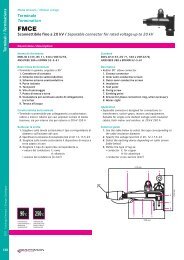
FMCE Sconnettibile fino a 20 kV / Separable connector for rated voltage up to 20 kV............................... pag. 134<br />
FMCTs - 400 Sconnettibile fino a 36 kV / Separable connector up to 36 kV............................................ pag. 136<br />
FMCTXs - 630/C Sconnettibile fino a 36 kV / Separable connector up to 36 kV....................................... pag. 140<br />
Giunti / Joints<br />
ECOSPEED TM Monoblocco retraibile a freddo per U m<br />
fino a 36 kV /<br />
Coldshrinkable straight through joints for U m<br />
up to 36 kV................................................................... pag. 144<br />
RETRACFIT Termo-elastico fino a 20 kV / Thermoelastic joints for rated voltage up to 20 kV..................... pag. 146<br />
SGE-RI POLIVALENTE/MULTIFUNCTION<br />
A resina iniettata fino a 20 kV / Injected resin joints for rated voltage up to 20 kV................................... pag. 147<br />
4 catalogo <strong>cavi</strong> e <strong>accessori</strong> <strong>2013</strong> / cables AND <strong>accessori</strong>es catalogue <strong>2013</strong>
Accessori / Accessories<br />
Guaine / Sheath<br />
SMW-M Termorestringente a medio spessore con collante / Heatshrinkable, medium wall, coated ............ pag. 148<br />
Lubrificanti / Lubricants<br />
RAPID SLIDE Per infilaggio dei <strong>cavi</strong> / For cable insertion.................................................................... pag. 149<br />
Barriere tagliafiamma / Fire barriers<br />
DIAFRAMMA / DIAPHRAGM LITEBOARD<br />
Resistente al fuoco / Fire resistant............................................................................................... pag. 150<br />
DIAFRAMMA / DIAPHRAGM MINIBAG S250<br />
Resistente al fuoco / Fire resistant............................................................................................... pag. 151<br />
MASTICE / SEALANT SEALANT T902-T902/EL<br />
Mastice intumescente per sigillature / Intumescent sealant agent...................................................... pag. 152<br />
SPECIALE MALTA / SPECIAL MORTAR MD1<br />
Malta resistente al fuoco / Fire resistant mortar.............................................................................. pag. 153<br />
COLLARE / COLLAR COLLAR C200<br />
Resistente al fuoco per tubazioni combustibili / Fire resistant for combustible pipes................................ pag. 154<br />
NASTRI / WRAPS<br />
Resistente al fuoco a base intumescente / Fire resistant intumescent.................................................. pag. 156<br />
5
Dati tecnici / Technical data<br />
Bassa tensione / Low voltage<br />
Coefficienti di correzione delle portate di corrente / Correction coefficients for current ratings<br />
Temperatura dell’ambiente diversa da quella di riferimento /<br />
Ambient temperature different from the conductor’s operating temperature......................................... pag. 162<br />
Cavi posati in aria - distanziati / Cables laying in air - separated.......................................................... pag. 162<br />
Cavi posati in aria - a contatto / Cables laying in air - in contact........................................................... pag. 163<br />
Cavi posati in terra / Buried cables............................................................................................... pag. 165<br />
Disposizioni delle fasi / Phase splitting<br />
Cavi unipolari collegati in parallelo / Single core cables laying in line..................................................... pag. 166<br />
Resistenza e reattanza / Resistance and reactance<br />
Cavi isolati in materiale termoplastico / Cables insulated with thermoplastic compounds......................... pag. 166<br />
Cavi isolati in materiale elastomerico / Cables insulated with elastomeric compounds............................. pag. 167<br />
Caduta di tensione / Voltage drop<br />
Coefficienti (Ct) per il calcolo della caduta di tensione in corrente alternata /<br />
Voltage drop coefficients (Ct) in AC............................................................................................... pag. 169<br />
Corrente di cortocircuito / Short-circuit current<br />
Corrente massima di cortocircuito / Maximum short-circuit current..................................................... pag. 170<br />
Corrente minima di cortocircuito / Minimum short-circuit current........................................................ pag. 171<br />
Protezione delle condutture / Circuit protection ......................................................................... pag. 172<br />
6 catalogo <strong>cavi</strong> e <strong>accessori</strong> <strong>2013</strong> / cables AND <strong>accessori</strong>es catalogue <strong>2013</strong>
Dati tecnici / Technical data<br />
Media tensione / Medium voltage<br />
Coefficienti di correzione delle portate di corrente / Correction coefficients for current ratings<br />
Temperatura dell’ambiente diversa da quella di riferimento /<br />
Ambient temperature different from the conductor’s operating temperature......................................... pag. 176<br />
Cavi unipolari posati in aria - spaziati in orizzontale o verticale /<br />
Single core cables laying in air - separated (horizontally or vertically)..................................................... pag. 176<br />
Cavi tripolari posati in aria - distanziati / Three core cables laying in air - separated.................................. pag. 177<br />
Cavi tripolari posati a trifoglio in aria - a contatto / Three core cables laying in air - in contact..................... pag. 178<br />
Cavi unipolari posati a trifoglio in aria / Single core cables laying in air in trefoil formation......................... pag. 178<br />
Cavi tripolari (o terne di <strong>cavi</strong> unipolari a trifoglio) posati in terra /<br />
Three core buried cables (or 3 core systems in trefoil formation)........................................................... pag. 179<br />
Cavi tripolari (o terne di <strong>cavi</strong> unipolari a trifoglio) posati in tubo interrato /<br />
Three core buried cables (or 3 core systems in trefoil formation in buried duct)......................................... pag. 179<br />
Disposizioni delle fasi / Phase splitting<br />
Cavi posati a trifoglio / Cables laying in trefoil formation.................................................................... pag. 179<br />
Cavi posati in orizzontale o in verticale / Cables laying in line horizontally or vertically.............................. pag. 179<br />
Portata di corrente / Current carrying capacity............................................................................ pag. 179<br />
Resistenza e reattanza / Resistance and reactance<br />
Cavi isolati in materiale elastomerico / Cables insulated with elastomeric compounds............................. pag. 180<br />
Capacità / Capacitance<br />
Cavi isolati in materiale elastomerico (HEPR) /<br />
Cables insulated with elastomeric compounds (HEPR)...................................................................... pag. 182<br />
Cavi isolati in polietilene reticolato (XLPE) /<br />
Cables insulated with cross-linked polyethylene (XLPE)..................................................................... pag. 182<br />
Cavi MV power e <strong>cavi</strong> COMPACT 105 / MV power cables and COMPACT 105 cables................................... pag. 183<br />
Scelta della tensione di isolamento / Selecting insulation voltage<br />
Cavi isolati in materiale elastomerico / Cables insulated with elastomeric compounds............................. pag. 184<br />
Tabella delle norme / Standard table<br />
Tabella delle norme / Standard table......................................................................................... pag. 186<br />
7
CATALOGO CAVI E ACCESSORI <strong>2013</strong> / CABLES & ACCESSORIES CATALOGUE <strong>2013</strong>
Cavi<br />
Cables<br />
Bassa tensione<br />
Low voltage
Cavi<br />
Cables<br />
Bassa tensione<br />
Low voltage<br />
Bassissima emissione di fumi e gas tossici pag. 10<br />
Very low emission of smoke and toxic gases<br />
Resistente al fuoco<br />
e a bassissima emissione di fumi e gas tossici pag. 26<br />
Fire resistant and very low emission of smoke<br />
and toxic gases<br />
Interno e cablaggio pag. 32<br />
Indoor cabling<br />
Energia e segnalamento pag. 38<br />
Power and signalling<br />
Servizio mobile pag. 50<br />
Mobile service<br />
Energia pag. 56<br />
Power<br />
Energia solare pag. 64<br />
Solar energy<br />
Ascensori pag. 68<br />
Elevators<br />
Comunicazione pag. 72<br />
Communication
BASSA TENSIONE / LOW VOLTAGE<br />
Bassissima emissione di fumi e gas tossici<br />
Very low emission of smoke and toxic gases<br />
H07Z1-K type 2/FM9<br />
450/750 V<br />
Norma di riferimento<br />
CEI 20-107 / CEI EN 50525<br />
Descrizione del cavo<br />
Anima<br />
Conduttore a corda flessibile di rame rosso<br />
Isolante<br />
Mescola termoplastica tipo AFUMEX (brevetto <strong>Prysmian</strong>)<br />
Colori disponibili<br />
- Da 1 a 6 mm 2 : giallo/verde, nero, blu chiaro, marrone, grigio<br />
- Da 10 a 25 mm 2 : giallo/verde, nero<br />
- Da 35 a 240 mm 2 : giallo/verde, nero<br />
Marcatura<br />
Stampigliatura:<br />
CEI 20-22 III IEMMEQU H07Z1-K type 2<br />
PRYSMIAN (G) FM9 450/750 V<br />
AFUMEX 750 PATENTED + ANNO<br />
Conforme ai requisiti essenziali delle direttive<br />
BT 2006/95/CE<br />
Applicazioni<br />
Idonei in ambienti ove sia fondamentale garantire<br />
la massima sicurezza alle persone quali: uffici, scuole,<br />
alberghi, supermercati, cinema, teatri, discoteche,<br />
metropolitane, edilizia residenziale, ecc.<br />
Indicati inoltre per installazione fissa entro tubazioni<br />
e canali porta<strong>cavi</strong>. Particolarmente consigliati per cablaggi<br />
interni di quadri elettrici, sia di distribuzione<br />
che di automazione, per la presenza di apparecchiature<br />
e sistemi particolarmente sensibili a fumi e a gas corrosivi<br />
Standard<br />
CEI 20-107 / CEI EN 50525<br />
Cable design<br />
Core<br />
Stranded flexible bare copper conductor<br />
Insulation<br />
Thermoplastic compound, AFUMEX type (<strong>Prysmian</strong> patent)<br />
Range of colours<br />
- From 1 to 6 mm 2 : yellow/green, black, light blue, brown,<br />
grey<br />
- From 10 to 25 mm 2 : yellow/green, black<br />
- From 35 to 240 mm 2 : yellow/green, black<br />
Marking<br />
CEI 20-22 III IEMMEQU H07Z1-K type 2<br />
PRYSMIAN (G) FM9 450/750 V<br />
AFUMEX 750 PATENTED + YEAR<br />
Compliant with the requirements of the BT 2006/95/CE<br />
directives<br />
Applications<br />
Suitable for busy transit areas in which it is essential<br />
to ensure safety for people, such as: offices, schools, hotels,<br />
supermarkets, cinemas, theatres, discotheques, tubes,<br />
residential buildings, etc.<br />
Recommended for fixed installation in conduits and<br />
protected trunking. Also suggested in switchboards, both<br />
for distribution and automation systems, due to the presence<br />
of particularly fragile equipments and systems towards<br />
smoke and corrosive gases<br />
TEMPERATURA<br />
FUNZIONAMENTO /<br />
OPERATING<br />
TEMPERATURE<br />
TEMPERATURA<br />
CORTOCIRCUITO /<br />
SHORT-CIRCUIT<br />
TEMPERATURE<br />
CEI 20-35<br />
EN 60332<br />
CEI EN 50266-2-4<br />
CEI 20.22 III<br />
CEI 20-37<br />
EN 50267<br />
CEI 20-38<br />
SENZA PIOMBO /<br />
LEAD FREE<br />
FLESSIBILE /<br />
FLEXIBLE<br />
Condizioni di posa / Laying conditions<br />
TEMPERATURA<br />
MIN. DI POSA -5°C /<br />
MINIMUM<br />
INSTALLATION<br />
TEMPERATURE -5°C<br />
TUBO<br />
O CANALINA<br />
IN ARIA /<br />
DUCT OR<br />
CABLE TRAY<br />
QUADRI<br />
ELETTRICI /<br />
SWITCHBOARDS<br />
CABLAGGIO /<br />
CABLING<br />
10 catalogo <strong>cavi</strong> e <strong>accessori</strong> <strong>2013</strong> / cables AND <strong>accessori</strong>es catalogue <strong>2013</strong>
BASSA TENSIONE / LOW VOLTAGE<br />
Bassissima emissione di fumi e gas tossici<br />
Very low emission of smoke and toxic gases<br />
H07Z1-K type 2/FM9<br />
450/750 V<br />
H07Z1-K type 2/FM9<br />
sezione diametro spessore diametro peso resistenza portata di corrente (A) con 3 <strong>cavi</strong> attivi raggio<br />
nominale indicativo medio esterno indicativo massima con temperatura ambiente di 30 °C minimo di<br />
conduttore isolante massimo del cavo a 20 °C in c. c. canale aperto (1) a contatto in tubo in aria curvatura<br />
conductor approximate average maximum approximate maximum DC permissible current rating (A) minimum<br />
cross-section diameter, insulation outer weight resistance 3 cores units at 30 °C bending<br />
conductor of the thickness diameter at 20 °C open trough (1) in duct in air in contact radius<br />
phase core<br />
(mm 2 ) (mm) (mm) (mm) (kg/km) (Ω/km) (mm)<br />
1 conduttore / 1 core<br />
1,5 1,5 0,7 3,5 19 13,3 - 15,5 14<br />
2,5 1,9 0,8 4,2 30 7,98 - 21 17<br />
4,0 2,5 0,8 4,8 45 4,95 - 28 19<br />
6,0 3,0 0,8 6,3 62 3,30 - 36 25<br />
10,0 3,9 1,0 7,6 105 1,91 57 50 30<br />
16,0 5,0 1,0 8,8 160 1,21 76 68 35<br />
25,0 6,5 1,2 11,0 260 0,780 101 89 45<br />
35,0 7,6 1,2 12,5 340 0,554 125 110 50<br />
50,0 9,3 1,4 14,5 490 0,386 151 134 60<br />
70,0 11,0 1,4 17,0 670 0,272 192 171 70<br />
95,0 12,5 1,5 19,0 880 0,206 232 207 80<br />
120,0 15,4 1,6 21,0 1160 0,161 269 239 85<br />
150,0 16,5 1,8 23,5 1370 0,129 309 275 95<br />
185,0 18,3 2,0 26,0 1700 0,106 353 314 100<br />
240,0 21,5 2,2 29,5 2300 0,0801 415 369 120<br />
Questo prodotto è coperto da almeno uno dei seguenti brevetti - e dai corrispondenti brevetti internazionali: EP-893, 801; EP-893, 802;<br />
WO 99/05688; WO 00/19452<br />
This product is protected by at least one of the following patent applications - and foreign counterparts: EP-893, 801; EP-893, 802;<br />
WO 99/05688; WO 00/19452<br />
(1)<br />
In un canale rispondente alle Norme CEI 23-31 e 23-32, ma non provvisto di coperchio, sono ammessi ma non raccomandati, <strong>cavi</strong> senza guaina,<br />
purché esso sia installato fuori dalla portata di mano e non sia soggetto a sollecitazioni meccaniche (Norma CEI 64-8/2 Gennaio 1998 Capitolo<br />
26, 3 commenti)<br />
In conformity with the CEI 23-31 and 23-32 standards, a trough with no cover, admits (but not recommends) the use of cables without sheath,<br />
only if not subjected to mechanical stress and within reach (CEI Standard 64-8/2 January 1998 Chapter 26, 3 comments)<br />
Note / Notes:<br />
Le portate sono state calcolate nel caso di una conduttura costituita da 3-4 <strong>cavi</strong> con solo 3 conduttori attivi<br />
Current carrying capacities are calculated assuming a conduit consisting of 3/4 cables with only 3 working conductors<br />
11
BASSA TENSIONE / LOW VOLTAGE<br />
Bassissima emissione di fumi e gas tossici<br />
Very low emission of smoke and toxic gases<br />
N07G9-K<br />
450/750 V<br />
Norma di riferimento<br />
CEI 20-38<br />
Descrizione del cavo<br />
Anima<br />
Conduttore a corda flessibile di rame rosso<br />
Isolante<br />
Elastomerico reticolato di qualità G9<br />
Colori disponibili<br />
- Da 1,5 a 6 mm 2 : giallo/verde, nero, blu chiaro, marrone,<br />
grigio<br />
- Da 10 a 25 mm 2 : giallo/verde, nero<br />
- Da 35 a 50 mm 2 : nero<br />
Marcatura<br />
Stampigliatura ad inchiostro speciale:<br />
CEI 20-22 II / CEI 20-38 IEMMEQU N07G9-K ENC 1X<br />
AFUMEX PRYSMIAN<br />
Conforme ai requisiti essenziali delle direttive<br />
BT 2006/95/CE<br />
Applicazioni<br />
Idonei in ambienti ove sia fondamentale garantire<br />
la massima sicurezza alle persone quali: uffici, scuole,<br />
alberghi, supermercati, cinema, teatri, discoteche,<br />
metropolitane, edilizia residenziale, ecc.<br />
Indicati inoltre per installazione fissa entro tubazioni<br />
e canali porta<strong>cavi</strong> e per cablaggi interni di quadri elettrici<br />
Standard<br />
CEI 20-38<br />
Cable design<br />
Core<br />
Stranded flexible bare copper conductor<br />
Insulation<br />
Cross-linked elastomeric compound, G9 type<br />
Range of colours<br />
- From 1,5 to 6 mm 2 : yellow/green, black, light blue, brown,<br />
grey<br />
- From 10 to 25 mm 2 : yellow/green, black<br />
- From 35 to 50 mm 2 : black<br />
Marking<br />
Special ink marking:<br />
CEI 20-22 II / CEI 20-38 IEMMEQU N07G9-K ENC 1X<br />
AFUMEX PRYSMIAN<br />
Compliant with the requirements of the BT 2006/95/CE<br />
directives<br />
Applications<br />
Suitable for busy transit areas in which it is essential<br />
to ensure safety for people, such as: offices, schools, hotels,<br />
supermarkets, cinemas, theatres, discotheques, tubes,<br />
residential buildings, etc. Recommended for fixed<br />
installation in conduits and protected trunking<br />
in switchboards<br />
TEMPERATURA<br />
FUNZIONAMENTO /<br />
OPERATING<br />
TEMPERATURE<br />
TEMPERATURA<br />
CORTOCIRCUITO /<br />
SHORT-CIRCUIT<br />
TEMPERATURE<br />
CEI 20-35<br />
EN 60332<br />
CEI 20.22 III<br />
CEI 20-37<br />
EN 50267<br />
CEI 20-38<br />
SENZA PIOMBO /<br />
LEAD FREE<br />
FLESSIBILE /<br />
FLEXIBLE<br />
Condizioni di posa / Laying conditions<br />
TEMPERATURA<br />
MIN. DI POSA -15°C /<br />
MINIMUM<br />
INSTALLATION<br />
TEMPERATURE -15°C<br />
TUBO<br />
O CANALINA<br />
IN ARIA /<br />
DUCT OR<br />
CABLE TRAY<br />
QUADRI<br />
ELETTRICI /<br />
SWITCHBOARDS<br />
CABLAGGIO /<br />
CABLING<br />
12 catalogo <strong>cavi</strong> e <strong>accessori</strong> <strong>2013</strong> / cables AND <strong>accessori</strong>es catalogue <strong>2013</strong>
BASSA TENSIONE / LOW VOLTAGE<br />
Bassissima emissione di fumi e gas tossici<br />
Very low emission of smoke and toxic gases<br />
N07G9-K<br />
450/750 V<br />
N07G9-K<br />
sezione diametro spessore diametro peso resistenza portata di corrente (A) con 3 <strong>cavi</strong> attivi raggio<br />
nominale indicativo medio esterno indicativo massima con temperatura ambiente di 30 °C minimo di<br />
conduttore isolante massimo del cavo a 20 °C in c. c. canale aperto (1) a contatto in tubo in aria curvatura<br />
conductor approximate average maximum approximate maximum DC permissible current rating (A) minimum<br />
cross-section diameter, insulation outer weight resistance 3 cores units at 30 °C bending<br />
conductor of the thickness diameter at 20 °C open trough (1) in duct in air in contact radius<br />
phase core<br />
(mm 2 ) (mm) (mm) (mm) (kg/km) (Ω/km) (mm)<br />
1 conduttore / Single core - tab. CEI-UNEL 35368<br />
1,5 1,5 0,7 3,5 21 13,3 20 20 14<br />
2,5 1,9 0,8 4,2 32 7,98 28 28 17<br />
4,0 2,4 0,8 4,8 47 4,95 37 37 19<br />
6,0 3,0 0,8 6,3 66 3,30 48 48 25<br />
10,0 4,1 1,0 7,6 114 1,91 71 66 30<br />
16,0 5,2 1,0 8,8 172 1,21 96 88 35<br />
25,0 6,3 1,2 11,0 260 0,780 127 117 45<br />
35,0 7,7 1,2 12,5 360 0,554 157 144 50<br />
50,0 9,4 1,4 14,5 550 0,386 190 175 60<br />
70,0 10,9 1,4 17,0 700 0,272 242 222 70<br />
95,0 12,7 1,6 19,0 960 0,206 293 269 80<br />
(1)<br />
In un canale rispondente alle Norme CEI 23-31 e 23-32, ma non provvisto di coperchio, sono ammessi ma non raccomandati, <strong>cavi</strong> senza guaina,<br />
purché esso sia installato fuori dalla portata di mano e non sia soggetto a sollecitazioni meccaniche (Norma CEI 64-8/2 Gennaio 1998 Capitolo<br />
26, 3 commenti)<br />
In conformity with the CEI 23-31 and 23-32 standards, a trough with no cover, admits (but not recommends) the use of cables without sheath,<br />
only if not subjected to mechanical stress and within reach (CEI Standard 64-8/2 January 1998 Chapter 26, 3 comments)<br />
Note / Notes:<br />
Le portate sono state calcolate nel caso di una conduttura costituita da 3-4 <strong>cavi</strong> con solo 3 conduttori attivi<br />
Current carrying capacities are calculated assuming a conduit consisting of 3/4 cables with only 3 working conductors<br />
13
BASSA TENSIONE / LOW VOLTAGE<br />
Bassissima emissione di fumi e gas tossici<br />
Very low emission of smoke and toxic gases<br />
FM90Z1<br />
450/750 V<br />
Norma di riferimento<br />
IMQ-CPT-049<br />
Descrizione del cavo<br />
Anima<br />
Conduttore a corda rotonda flessibile di rame rosso<br />
Isolante<br />
Mescola termoplastica tipo AFUMEX (brevetto <strong>Prysmian</strong>)<br />
Colori disponibili<br />
blu chiaro-marrone<br />
giallo/verde-blu-marrone<br />
Standard<br />
IMQ-CPT-049<br />
Cable design<br />
Core<br />
Stranded flexible bare copper conductor<br />
Insulation<br />
Thermoplastic compound, AFUMEX type (<strong>Prysmian</strong> patent)<br />
Range of colours<br />
light blue-brown<br />
yellow/green-light blue-brown<br />
giallo/verde-marrone<br />
nero-grigio<br />
giallo/verde-blu chiaro<br />
marrone-nero-grigio<br />
yellow/green-brown<br />
black-grey<br />
yellow/green-light blue<br />
brown-black-grey<br />
Guaina<br />
Mescola termoplastica tipo AFUMEX a base di poliolefine<br />
Marcatura<br />
CEI 20-22 III CAT. C FM90Z1 450/750 V AFUMEX FLEX<br />
PRYSMIAN (G) SAFETY LINE PATENTED<br />
Conforme ai requisiti essenziali delle direttive<br />
BT 2006/95/CE<br />
Applicazioni<br />
Idoneo per installazioni all’interno di locali secchi o umidi.<br />
Adatti per servizio mobile e per posa fissa, soprattutto<br />
in presenza di controsoffittatura e pavimenti flottanti.<br />
Luoghi d’impiego: fiere, ospedali, cinema, teatri, uffici, ecc.<br />
Sheath<br />
Polyolefin-based thermoplastic compound, AFUMEX type<br />
Marking<br />
CEI 20-22 III CAT. C FM90Z1 450/750 V AFUMEX FLEX<br />
PRYSMIAN (G) SAFETY LINE PATENTED<br />
Compliant with the requirements of the BT 2006/95/CE<br />
directives<br />
Applications<br />
Suitable for indoor installation in wet or dry environments.<br />
For mobile applications and for fixed installation, especially<br />
for false ceilings and floating floors.<br />
Areas of application: exhibitions, hospitals, cinemas,<br />
theatres, offices, etc.<br />
TEMPERATURA<br />
FUNZIONAMENTO /<br />
OPERATING<br />
TEMPERATURE<br />
TEMPERATURA<br />
CORTOCIRCUITO /<br />
SHORT-CIRCUIT<br />
TEMPERATURE<br />
CEI 20-35<br />
EN 60332<br />
CEI EN 50266-2-4<br />
CEI 20.22 III<br />
CEI 20-37<br />
EN 50267<br />
CEI 20-38<br />
SENZA PIOMBO /<br />
LEAD FREE<br />
FLESSIBILE /<br />
FLEXIBLE<br />
Condizioni di posa / Laying conditions<br />
TEMPERATURA<br />
MIN. DI POSA -5°C /<br />
MINIMUM<br />
INSTALLATION<br />
TEMPERATURE -5°C<br />
TUBO<br />
O CANALINA<br />
IN ARIA /<br />
DUCT OR<br />
CABLE TRAY<br />
SERVIZIO MOBILE<br />
INTERNO /<br />
INDOOR MOBILE<br />
APPLICATION<br />
ARIA LIBERA /<br />
OPEN AIR<br />
14 catalogo <strong>cavi</strong> e <strong>accessori</strong> <strong>2013</strong> / cables AND <strong>accessori</strong>es catalogue <strong>2013</strong>
BASSA TENSIONE / LOW VOLTAGE<br />
Bassissima emissione di fumi e gas tossici<br />
Very low emission of smoke and toxic gases<br />
FM90Z1<br />
450/750 V<br />
FM90Z1<br />
sezione diametro spessore diametro peso resistenza portata di corrente (A) con temperatura libera raggio minimo di curvatura<br />
nominale indicativo medio esterno indicativo massima ambiente di 30 °C in aria libera<br />
conduttore isolante massimo del cavo a 20 °C in c. c. posa in tubo servizio posa servizio<br />
fissa o canaletta mobile fissa mobile<br />
conductor approximate average maximum approximate maximum DC permissible current rating (A) at 30 °C minimum bending radius<br />
cross-section diameter, insulation outer weight resistance fixed in duct or mobile fixed mobile<br />
conductor of thickness diameter at 20 °C installation cable tray application installation application<br />
the phase core<br />
(mm 2 ) (mm) (mm) (mm) (kg/km) (Ω/km) (mm) (mm)<br />
2 conduttori / 2 cores (capit. tecn. di prova / technical specifications IMQ-CPT-049)<br />
1,0 1,3 0,7 8,8 88 19,5 15 13,5 12,5 35 90<br />
1,5 1,5 0,7 9,3 105 13,3 22 16,5 17 40 95<br />
2,5 1,9 0,8 11,0 155 7,98 30 23 22,5 45 110<br />
4,0 2,4 0,8 12,5 205 4,95 40 30 30 50 130<br />
6,0 3,0 0,9 14,5 285 3,30 51 38 40 60 140<br />
3 conduttori con giallo/verde / 3 cores with yellow/green (capit. tecn. di prova / technical specifications IMQ-CPT-049)<br />
1,0 1,3 0,7 9,4 100 19,50 15 13,5 12,5 40 95<br />
1,5 1,5 0,7 9,8 120 13,30 22 16,5 17,0 40 100<br />
2,5 1,9 0,8 12,0 185 7,98 30 23,0 22,5 50 120<br />
4,0 2,4 0,8 13,5 245 4,95 40 30,0 30,0 55 140<br />
6,0 3,0 0,9 15,5 345 3,30 51 38,0 40,0 65 160<br />
4 conduttori con giallo/verde / 4 cores with yellow/green (capit. tecn. di prova / technical specifications IMQ-CPT-049)<br />
1,0 1,3 0,7 10,0 120 19,50 13,6 12 11,5 40 100<br />
1,5 1,5 0,7 11,0 150 13,30 18,5 15 15,0 45 110<br />
2,5 1,9 0,8 13,0 220 7,98 25,0 20 21,0 55 130<br />
4,0 2,4 0,8 14,5 300 4,95 34,0 27 28,0 60 150<br />
6,0 3,0 0,9 17,0 420 3,30 43,0 34 36,0 70 170<br />
5 conduttori con giallo/verde / 5 cores with yellow/green (capit. tecn. di prova / technical specifications IMQ-CPT-049)<br />
1,0 1,3 0,7 11,0 150 19,50 13,6 12 11,5 45 110<br />
1,5 1,5 0,7 12,0 185 13,30 18,5 15 15,0 50 120<br />
2,5 1,9 0,8 14,0 270 7,98 25,0 20 21,0 60 140<br />
4,0 2,4 0,8 16,5 375 4,95 34,0 27 28,0 70 170<br />
6,0 3,0 0,9 18,5 520 3,30 43,0 34 36,0 75 190<br />
Comando e segnalamento / Control and signalling - FM90Z1<br />
Sezione 1 mm 2 / 1 mm 2 cross-section (capit. tecn. di prova / technical specifications IMQ-CPT-049)<br />
7 G 1,3 0,6 11,0 145 19,5 10,0 9,0 9,0 45 110<br />
10 G 1,3 0,6 14,0 215 19,5 9,5 8,5 8,0 60 140<br />
12 G 1,3 0,6 15,0 245 19,5 9,0 8,0 7,5 60 150<br />
14 G 1,3 0,6 15,5 295 19,5 8,5 7,5 7,0 65 160<br />
16 G 1,3 0,6 16,5 315 19,5 8,0 7,0 7,0 70 170<br />
19 G 1,3 0,6 17,5 380 19,5 7,5 7,0 6,5 70 180<br />
24 G 1,3 0,6 20,5 485 19,5 6,5 6,5 6,0 85 210<br />
Sezione 1,5 mm 2 / 1,5 mm 2 cross-section (capit. tecn. di prova / technical specifications IMQ-CPT-049)<br />
7 G 1,5 0,7 13,0 210 13,3 13,0 11,5 11,0 55 130<br />
10 G 1,5 0,7 16,5 300 13,3 12,0 10,5 10,0 70 170<br />
12 G 1,5 0,7 17,5 345 13,3 11,0 10,0 9,5 70 180<br />
14 G 1,5 0,7 18,5 390 13,3 10,5 9,5 9,0 75 190<br />
16 G 1,5 0,7 19,5 450 13,3 10,0 9,0 8,5 80 200<br />
19 G 1,5 0,7 20,5 510 13,3 9,5 8,5 8,0 85 210<br />
24 G 1,5 0,7 24,0 655 13,3 9,0 8,0 7,5 100 240<br />
15
BASSA TENSIONE / LOW VOLTAGE<br />
Bassissima emissione di fumi e gas tossici<br />
Very low emission of smoke and toxic gases<br />
FG7M1<br />
0,6/1 kV<br />
1,5 2,5 4 6 10 16<br />
Codice identificativo / Identification code<br />
Norma di riferimento<br />
CEI 20-13<br />
Descrizione del cavo<br />
Anima<br />
Conduttore a corda rotonda flessibile di rame rosso ricotto<br />
Isolante<br />
Gomma HEPR ad alto modulo, che conferisce al cavo<br />
elevate caratteristiche elettriche, meccaniche e termiche<br />
Colori delle anime<br />
nero<br />
Guaina<br />
Termoplastica speciale di qualità M1, colore verde con banda<br />
colorata fino a 16 mm 2<br />
Marcatura<br />
Stampigliatura ad inchiostro speciale:<br />
CEI 20-22 III CAT. C IEMMEQU AFUMEX 1000 AMICO<br />
PRYSMIAN (G) <br />
SAFETY LINE PATENTED<br />
Marcatura metrica progressiva<br />
Conforme ai requisiti essenziali delle direttive<br />
BT 2006/95/CE<br />
Applicazioni<br />
Cavi unipolari per energia a bassissima emissione di fumi<br />
e gas tossici (limiti previsti dalla CEI 20-38 con modalità di<br />
prova previste dalla CEI 20-37). Idonei in ambienti a rischio<br />
d’incendio ove sia fondamentale garantire la salvaguardia<br />
delle persone e preservare gli impianti e le apparecchiature<br />
dall’attacco dei gas corrosivi (esempio: scuole, ospedali,<br />
alberghi, supermercati, metropolitane, cinema, teatri,<br />
discoteche, uffici, ecc.).<br />
Adatti per posa fissa su muratura e su strutture metalliche<br />
all’interno e all’esterno<br />
Standard<br />
CEI 20-13<br />
Cable design<br />
Core<br />
Stranded flexible annealed bare copper conductor<br />
Insulation<br />
High module HEPR rubber, with higher electrical,<br />
mechanical and thermal performances<br />
Core identification<br />
black<br />
Sheath<br />
Special thermoplastic, M1 type; colour green with colured line<br />
up to 16 mm 2<br />
Marking<br />
Special ink marking:<br />
CEI 20-22 III CAT. C IEMMEQU AFUMEX 1000 AMICO<br />
PRYSMIAN (G) <br />
SAFETY LINE PATENTED<br />
Progressive metric marking<br />
Compliant with the requirements of the BT 2006/95/CE<br />
directives<br />
Applications<br />
Single core power cables with low emission of smoke and<br />
toxic gases (according the CEI 20-38 in conformity with<br />
CEI 20-37 for expected tests). Suitable for environments<br />
with high fire hazards risk, where it’s essential to guarantee<br />
the safety of people and preserve systems and equipments<br />
from the corrosive gases (e.g. schools, hospitals,<br />
public premises, hotels, supermarkets, tubes, cinemas,<br />
theatres, discotheques, public offices).<br />
For fixed installation, both indoor and outdoor, on walls<br />
and metallic frames<br />
TEMPERATURA<br />
FUNZIONAMENTO /<br />
OPERATING<br />
TEMPERATURE<br />
TEMPERATURA<br />
CORTOCIRCUITO /<br />
SHORT-CIRCUIT<br />
TEMPERATURE<br />
CEI 20-35<br />
EN 60332<br />
CEI EN 50266-2-4<br />
CEI 20.22 III<br />
CEI 20-37<br />
EN 50267<br />
CEI 20-38<br />
SENZA PIOMBO /<br />
LEAD FREE<br />
FLESSIBILE /<br />
FLEXIBLE<br />
Condizioni di posa / Laying conditions<br />
TEMPERATURA<br />
MIN. DI POSA -5°C /<br />
MINIMUM<br />
INSTALLATION<br />
TEMPERATURE -5°C<br />
TUBO<br />
O CANALINA<br />
IN ARIA /<br />
DUCT OR<br />
CABLE TRAY<br />
CANALE<br />
INTERRATO /<br />
BURIED TROUGH<br />
TUBO<br />
INTERRATO /<br />
BURIED DUCT<br />
ARIA LIBERA /<br />
OPEN AIR<br />
INTERRATO CON<br />
PROTEZIONE /<br />
BURIED<br />
WITH PROTECTION<br />
16 catalogo <strong>cavi</strong> e <strong>accessori</strong> <strong>2013</strong> / cables AND <strong>accessori</strong>es catalogue <strong>2013</strong>
BASSA TENSIONE / LOW VOLTAGE<br />
Bassissima emissione di fumi e gas tossici<br />
Very low emission of smoke and toxic gases<br />
FG7M1<br />
0,6/1 kV<br />
FG7M1<br />
sezione diametro spessore diametro peso resistenza portata di corrente (A) con temperatura ambiente di raggio<br />
nominale indicativo medio esterno indicativo massima 30 °C in 30 °C in 20 °C 20 °C minimo di<br />
conduttore isolante massimo del cavo a 20 °C aria tubo in aria interrato in tubo interrato curvatura<br />
in c. c.<br />
conductor approx. average maximum approx. maximum permissible current rating (A) minimum<br />
cross-section diameter, insulation outer weight DC in open air in duct in in buried duct buried bending<br />
conductor thickness diameter resistance at 30 °C air at 30 °C at 20 °C at 20 °C radius<br />
of the at 20 °C<br />
phase core<br />
(mm 2 ) (mm) (mm) (mm) (kg/km) (Ω/km) =1°C m/W =1,5 °C m/W =1 °C m/W =1,5 °C m/W (mm)<br />
1 conduttore / Single core - tab. CEI-UNEL 35382<br />
10 4,1 0,7 9,4 150 1,91 80 66 63 59 97 85 45<br />
16 5,2 0,7 10,4 200 1,21 107 88 82 77 125 110 50<br />
25 6,3 0,9 12,2 300 0,780 135 117 108 100 160 141 60<br />
35 7,7 0,9 13,6 390 0,554 169 144 132 121 191 169 60<br />
50 9,4 1,0 15,4 540 0,386 207 175 166 150 226 199 70<br />
70 10,9 1,1 17,3 740 0,272 268 222 204 184 277 244 80<br />
95 12,7 1,1 19,4 940 0,206 328 269 242 217 331 292 90<br />
120 14,5 1,2 21,4 1200 0,161 383 312 274 251 377 332 95<br />
150 15,6 1,4 23,8 1480 0,129 444 355 324 287 420 370 100<br />
185 17,8 1,6 26,0 1830 0,106 510 417 364 323 476 419 110<br />
240 20,0 1,7 29,0 2340 0,0801 607 490 427 379 550 484 130<br />
300 23,1 1,8 32,0 2950 0,0641 703 - 484 429 620 546 140<br />
Questo prodotto è coperto da almeno uno dei seguenti brevetti - e dai corrispondenti brevetti internazionali: EP-893, 801; EP-893, 802;<br />
WO 99/05688; WO 00/19452<br />
This product is protected by at least one of the following patent applications - and foreign counterparts: EP-893, 801; EP-893, 802;<br />
WO 99/05688; WO 00/19452<br />
Note / Notes:<br />
Le portate dei <strong>cavi</strong> unipolari sono state calcolate per tre <strong>cavi</strong> a trifoglio. Le portate dei <strong>cavi</strong> interrati sono state calcolate considerando una<br />
profondità di posa di 0,8 m<br />
Current carrying capacities for single core cables are calculated assuming three cables laying in trefoil formation. Current carrying capacities for<br />
buried cables are calculated assuming a laying depth of 0,8 m<br />
17
BASSA TENSIONE / LOW VOLTAGE<br />
Bassissima emissione di fumi e gas tossici<br />
Very low emission of smoke and toxic gases<br />
FG7OM1<br />
0,6/1 kV<br />
1,5 2,5 4 6<br />
Codice identificativo / Identification code<br />
Norma di riferimento<br />
CEI 20-13<br />
Descrizione del cavo<br />
Anima<br />
Conduttore a corda rotonda flessibile di rame rosso ricotto<br />
Isolante<br />
Gomma HEPR ad alto modulo, che conferisce al cavo<br />
elevate caratteristiche elettriche, meccaniche e termiche<br />
Colori delle anime<br />
blu chiaro-marrone<br />
marrone-nero-grigio<br />
giallo/verde-blu chiaro-marrone<br />
blu chiaro-marrone<br />
nero-grigio<br />
giallo/verde-marrone<br />
nero-grigio<br />
Le anime dei <strong>cavi</strong> per segnalamento sono nere,<br />
numerate ed è previsto il conduttore di terra giallo/verde<br />
Guaina<br />
Termoplastica speciale di qualità M1:<br />
- Colore verde con banda colorata fino a 6 mm 2 per <strong>cavi</strong> energia<br />
- Colore verde per sezioni ≥ a 16 mm 2<br />
- Colore verde per tutti i <strong>cavi</strong> di segnalamento per sezioni da<br />
1,5 e 2,5 mm 2<br />
Marcatura<br />
Stampigliatura ad inchiostro speciale:<br />
CEI 20-22 III CAT. C IEMMEQU AFUMEX 1000 AMICO<br />
PRYSMIAN (G) <br />
SAFETY LINE PATENTED<br />
Marcatura metrica progressiva<br />
Conforme ai requisiti essenziali delle direttive<br />
BT 2006/95/CE<br />
giallo/verde-blu chiaro<br />
marrone-nero-grigio<br />
Applicazioni<br />
Cavi multipolari per energia e segnalamento a bassissima<br />
emissione di fumi e gas tossici (limiti previsti dalla CEI 20-38<br />
con modalità di prova previste dalla CEI 20-37). Idonei in<br />
ambienti a rischio d’incendio ove sia fondamentale<br />
garantire la salvaguardia delle persone e preservare gli<br />
impianti e le apparecchiature dall’attacco dei gas corrosivi<br />
(esempio: scuole, ospedali, alberghi, supermercati,<br />
metropolitane, cinema, teatri, discoteche, uffici, ecc.).<br />
Adatti per posa fissa su muratura e su strutture metalliche<br />
all’interno e all’esterno<br />
Standard<br />
CEI 20-13<br />
Cable design<br />
Core<br />
Stranded flexible annealed bare copper conductor<br />
Insulation<br />
High module HEPR rubber, with higher electrical,<br />
mechanical and thermal performances<br />
Core identification<br />
light blue-brown<br />
brown-black-grey<br />
yellow/green-light blue-brown<br />
light blue-brown<br />
black-grey<br />
yellow/green-brown<br />
black-grey<br />
yellow/green-light blue<br />
brown-black-grey<br />
Conductors for signalling cables are black, with numbers<br />
and with yellow/green earth conductor<br />
Sheath<br />
Special thermoplastic, M1 type:<br />
- Colour green with colured line up to 6 mm 2 for energy cables<br />
- Colour green for cross-section ≥ 16 mm 2<br />
- Colour green for signal cables with cross-section 1.5<br />
and 2.5 mm 2<br />
Marking<br />
Special ink marking:<br />
CEI 20-22 III CAT. C IEMMEQU AFUMEX 1000 AMICO<br />
PRYSMIAN (G) <br />
SAFETY LINE PATENTED<br />
Progressive metric marking<br />
Compliant with the requirements of the BT 2006/95/CE<br />
directives<br />
Applications<br />
Multicore power and signalling cables with low emission<br />
of smoke and toxic gases (according the CEI 20-38<br />
in conformity with CEI 20-37 for expected tests). Suitable for<br />
environments with high fire hazards risk, where it’s essential<br />
to guarantee the safety of people and preserve systems and<br />
equipments from the corrosive gases (e.g. schools, hospitals,<br />
public premises, hotels, supermarkets, tubes, cinemas,<br />
theatres, discotheques, public offices). For fixed installation,<br />
both indoor and outdoor, on walls and metallic frames<br />
TEMPERATURA<br />
FUNZIONAMENTO /<br />
OPERATING<br />
TEMPERATURE<br />
TEMPERATURA<br />
CORTOCIRCUITO /<br />
SHORT-CIRCUIT<br />
TEMPERATURE<br />
CEI 20-35<br />
EN 60332<br />
CEI EN 50266-2-4<br />
CEI 20.22 III<br />
CEI 20-37<br />
EN 50267<br />
CEI 20-38<br />
SENZA PIOMBO /<br />
LEAD FREE<br />
FLESSIBILE /<br />
FLEXIBLE<br />
Condizioni di posa / Laying conditions<br />
TEMPERATURA<br />
MIN. DI POSA -5°C /<br />
MINIMUM<br />
INSTALLATION<br />
TEMPERATURE -5°C<br />
TUBO<br />
O CANALINA<br />
IN ARIA /<br />
DUCT OR<br />
CABLE TRAY<br />
CANALE<br />
INTERRATO /<br />
BURIED TROUGH<br />
TUBO<br />
INTERRATO /<br />
BURIED DUCT<br />
ARIA LIBERA /<br />
OPEN AIR<br />
INTERRATO CON<br />
PROTEZIONE /<br />
BURIED<br />
WITH PROTECTION<br />
18 catalogo <strong>cavi</strong> e <strong>accessori</strong> <strong>2013</strong> / cables AND <strong>accessori</strong>es catalogue <strong>2013</strong>
BASSA TENSIONE / LOW VOLTAGE<br />
Bassissima emissione di fumi e gas tossici<br />
Very low emission of smoke and toxic gases<br />
FG7OM1<br />
0,6/1 kV<br />
FG70M1<br />
sezione diametro spessore diametro peso resistenza portata di corrente (A) con temperatura ambiente di raggio<br />
nominale indicativo medio esterno indicativo massima 30 °C in 30 °C in 20 °C 20 °C minimo di<br />
conduttore isolante massimo del cavo a 20 °C aria tubo in aria interrato in tubo interrato curvatura<br />
in c. c.<br />
conductor approx. average maximum approx. maximum permissible current rating (A) minimum<br />
cross-section diameter, insulation outer weight DC in open air in duct in in buried duct buried bending<br />
conductor thickness diameter resistance at 30 °C air at 30 °C at 20 °C at 20 °C radius<br />
of the at 20 °C<br />
phase core<br />
(mm 2 ) (mm) (mm) (mm) (kg/km) (Ω/km) =1°C m/W =1,5 °C m/W =1 °C m/W =1,5 °C m/W (mm)<br />
2 conduttori / 2 cores - tab. CEI-UNEL 35382<br />
1,5 1,5 0,7 12,0 150 13,3 26 22 24 23 36 31 55<br />
2,5 1,9 0,7 13,0 190 7,98 36 30 31 30 47 41 60<br />
4,0 2,4 0,7 14,2 240 4,95 49 40 41 39 61 55 65<br />
6,0 3,0 0,7 15,4 310 3,30 63 51 52 49 77 68 70<br />
10,0 4,1 0,7 17,3 440 1,91 86 69 70 66 105 92 80<br />
16,0 5,2 0,7 19,4 600 1,21 115 91 92 86 136 120 90<br />
25,0 6,3 0,9 23,0 850 0,780 149 119 118 111 177 156 100<br />
35,0 7,7 0,9 25,7 1130 0,554 185 146 145 136 212 185 110<br />
50,0 9,4 1,0 29,3 1580 0,386 225 175 180 168 252 221 120<br />
3 conduttori / 3 cores - tab. CEI-UNEL 35382<br />
1,5 1,5 0,7 12,5 170 13,3 23 19,5 20 19 30 26 55<br />
2,5 1,9 0,7 13,6 220 7,98 32 26,0 26 25 40 36 60<br />
4,0 2,4 0,7 14,9 280 4,95 42 35,0 33 32 51 45 65<br />
6,0 3,0 0,7 16,2 370 3,30 54 44,0 43 41 65 56 70<br />
10,0 4,1 0,7 18,2 530 1,91 75 60,0 59 55 88 78 85<br />
16,0 5,2 0,7 20,6 740 1,21 100 80,0 76 72 114 101 90<br />
25,0 6,3 0,9 24,5 1060 0,780 127 105,0 100 93 148 130 110<br />
35,0 7,7 0,9 27,3 1420 0,554 158 128,0 122 114 178 157 120<br />
50,0 9,4 1,0 31,2 1960 0,386 192 154,0 152 141 211 185 130<br />
70,0 10,9 1,1 35,6 2700 0,272 246 194,0 189 174 259 227 150<br />
95,0 12,7 1,1 40,0 3430 0,206 298 233,0 226 206 311 274 170<br />
120,0 14,5 1,2 44,4 4390 0,161 346 268,0 260 238 355 311 190<br />
150,0 15,6 1,4 49,5 5400 0,129 399 300,0 299 272 394 345 210<br />
Questo prodotto è coperto da almeno uno dei seguenti brevetti - e dai corrispondenti brevetti internazionali: EP-893, 801; EP-893, 802;<br />
WO 99/05688; WO 00/19452<br />
This product is protected by at least one of the following patent applications - and foreign counterparts: EP-893, 801; EP-893, 802;<br />
WO 99/05688; WO 00/19452<br />
Note / Notes:<br />
Le portate dei <strong>cavi</strong> quadripolari e pentapolari sono state calcolate per tre conduttori attivi<br />
Le portate dei <strong>cavi</strong> interrati sono state calcolate considerando una profondità di posa di 0,8 m<br />
Current carrying capacities for cables consisting of 4/5 conductors are calculated assuming three working conductors<br />
Current carrying capacities for buried cables are calculated assuming a laying depth of 0,8 m<br />
19
BASSA TENSIONE / LOW VOLTAGE<br />
Bassissima emissione di fumi e gas tossici<br />
Very low emission of smoke and toxic gases<br />
FG7OM1<br />
0,6/1 kV<br />
FG70M1<br />
sezione diametro spessore diametro peso resistenza portata di corrente (A) con temperatura ambiente di raggio<br />
nominale indicativo medio esterno indicativo massima 30 °C in 30 °C in 20 °C 20 °C minimo di<br />
conduttore isolante massimo del cavo a 20 °C aria tubo in aria interrato in tubo interrato curvatura<br />
in c. c.<br />
conductor approx. average maximum approx. maximum permissible current rating (A) minimum<br />
cross-section diameter, insulation outer weight DC in open air in duct in in buried duct buried bending<br />
conductor thickness diameter resistance at 30 °C air at 30 °C at 20 °C at 20 °C radius<br />
of the at 20 °C<br />
phase core<br />
(mm 2 ) (mm) (mm) (mm) (kg/km) (Ω/km) =1°C m/W =1,5 °C m/W =1 °C m/W =1,5 °C m/W (mm)<br />
3 conduttori con giallo/verde / 3 cores with yellow/green - tab. CEI-UNEL 35382<br />
1,5 1,5 0,7 12,5 170 13,3 26 22 24 23 36 31 55<br />
2,5 1,9 0,7 13,6 220 7,98 36 30 31 30 47 41 60<br />
4,0 2,4 0,7 14,9 280 4,95 49 40 41 39 61 55 65<br />
6,0 3,0 0,7 16,2 370 3,30 63 51 52 49 77 68 70<br />
10,0 4,1 0,7 18,2 530 1,91 86 69 70 66 105 92 85<br />
16,0 5,2 0,7 20,6 740 1,21 115 91 92 86 136 120 90<br />
25,0 6,3 0,9 24,5 1060 0,780 149 119 118 111 177 156 110<br />
35,0 7,7 0,9 27,3 1420 0,554 185 146 145 136 212 185 120<br />
50,0 9,4 1,0 31,2 1960 0,386 225 175 180 168 252 221 130<br />
70,0 10,9 1,1 35,6 2700 0,272 289 221 223 207 310 272 150<br />
95,0 12,7 1,1 40,0 3430 0,206 352 265 265 245 371 325 170<br />
120,0 14,5 1,2 44,4 4390 0,161 410 305 310 284 423 370 190<br />
150,0 15,6 1,4 49,5 5400 0,129 473 334 356 324 472 414 210<br />
4 conduttori / 4 cores - tab. CEI-UNEL 35382<br />
1,5 1,5 0,7 13,4 200 13,3 23 19,5 20 19 30 26 60<br />
2,5 1,9 0,7 14,6 260 7,98 32 26 26 25 40 36 65<br />
4,0 2,4 0,7 16,0 330 4,95 42 35 33 32 51 45 70<br />
6,0 3,0 0,7 17,5 430 3,30 54 44 43 41 65 56 75<br />
10,0 4,1 0,7 19,8 640 1,91 75 60 59 55 88 78 90<br />
16,0 5,2 0,7 22,4 900 1,21 100 80 76 72 114 101 100<br />
25,0 6,3 0,9 26,8 1300 0,780 127 105 100 93 148 130 120<br />
35+1x25 7,7 0,9 29,2 1650 0,554 158 128 122 114 178 157 130<br />
50+1x25 9,4 1,0 32,4 2200 0,386 192 154 152 141 211 185 140<br />
70+1x35 10,9 1,1 37,0 3000 0,272 246 194 189 174 259 227 160<br />
95+1x50 12,7 1,1 42,0 3900 0,206 298 233 226 206 311 274 180<br />
120+1x70 14,5 1,2 46,9 4700 0,161 346 268 260 238 355 311 200<br />
150+1x95 15,6 1,4 52,5 6300 0,129 399 300 299 272 394 345 220<br />
4 conduttori con giallo/verde / 4 cores with yellow/green - tab. CEI-UNEL 35382<br />
1,5 1,5 0,7 13,4 200 13,3 23 19,5 20 19 30 26 60<br />
2,5 1,9 0,7 14,6 260 7,98 32 26 26 25 40 36 65<br />
4,0 2,4 0,7 16,0 330 4,95 42 35 33 32 51 45 70<br />
6,0 3,0 0,7 17,5 430 3,30 54 44 43 41 65 56 75<br />
10,0 4,1 0,7 19,8 640 1,91 75 60 59 55 88 78 90<br />
16,0 5,2 0,7 22,4 900 1,21 100 80 76 72 114 101 100<br />
25,0 6,3 0,9 26,8 1300 0,780 127 105 100 93 148 130 120<br />
35+1Gx25 7,7 0,9 29,2 1650 0,554 158 128 122 114 178 157 130<br />
50+1Gx25 9,4 1,0 32,4 2200 0,386 192 154 152 141 211 185 140<br />
70+1Gx35 10,9 1,1 37,0 3000 0,272 246 194 189 174 259 227 160<br />
95+1Gx50 12,7 1,1 42,0 3900 0,206 298 233 226 206 311 274 180<br />
120+1Gx70 14,5 1,2 46,9 4700 0,161 346 268 260 238 355 311 200<br />
150+1Gx95 15,6 1,4 52,5 6300 0,129 399 300 299 272 394 345 220<br />
Note / Notes:<br />
Le portate dei <strong>cavi</strong> quadripolari e pentapolari sono state calcolate per tre conduttori attivi. Le portate dei <strong>cavi</strong> interrati sono state calcolate<br />
considerando una profondità di posa di 0,8 m<br />
Current carrying capacities for cables consisting of 4/5 conductors are calculated assuming three working conductors. Current carrying capacities<br />
for buried cables are calculated assuming a laying depth of 0,8 m<br />
20 catalogo <strong>cavi</strong> e <strong>accessori</strong> <strong>2013</strong> / cables AND <strong>accessori</strong>es catalogue <strong>2013</strong>
BASSA TENSIONE / LOW VOLTAGE<br />
Bassissima emissione di fumi e gas tossici<br />
Very low emission of smoke and toxic gases<br />
FG7OM1<br />
0,6/1 kV<br />
FG70M1<br />
sezione diametro spessore diametro peso resistenza portata di corrente (A) con temperatura ambiente di raggio<br />
nominale indicativo medio esterno indicativo massima 30 °C in 30 °C in 20 °C 20 °C minimo di<br />
conduttore isolante massimo del cavo a 20 °C aria tubo in aria interrato in tubo interrato curvatura<br />
in c. c.<br />
conductor approx. average maximum approx. maximum permissible current rating (A) minimum<br />
cross-section diameter, insulation outer weight DC in open air in duct in in buried duct buried bending<br />
conductor thickness diameter resistance at 30 °C air at 30 °C at 20 °C at 20 °C radius<br />
of the at 20 °C<br />
phase core<br />
(mm 2 ) (mm) (mm) (mm) (kg/km) (Ω/km) =1°C m/W =1,5 °C m/W =1 °C m/W =1,5 °C m/W (mm)<br />
5 conduttori con giallo/verde / 5 cores with yellow/green - tab. CEI-UNEL 35382<br />
1,5 1,5 0,7 14,4 230 13,3 23 19,5 20 19 30 26 65<br />
2,5 1,9 0,7 15,6 310 7,98 32 26 26 25 40 36 70<br />
4,0 2,4 0,7 17,3 400 4,95 42 35 33 32 51 45 75<br />
6,0 3,0 0,7 18,9 520 3,30 54 44 43 41 65 56 80<br />
10,0 4,1 0,7 21,5 780 1,91 75 60 59 55 88 78 95<br />
16,0 5,2 0,7 24,4 1120 1,21 100 80 76 72 114 101 110<br />
25,0 6,3 0,9 29,3 1680 0,780 127 105 100 93 148 130 130<br />
35,0 7,7 0,9 32,8 2150 0,554 158 128 122 114 178 157 140<br />
50,0 9,4 1,0 38,2 3000 0,386 192 154 152 141 211 185 160<br />
Comando e segnalamento / Control and signalling - FG7OM1<br />
numero diametro spessore diametro peso resistenza portata di corrente (A) con temperatura ambiente di raggio<br />
conduttori indicativo medio esterno indicativo massima 30 °C 30 °C 20 °C minimo di<br />
conduttore isolante massimo del cavo a 20 °C in c. c. in aria in tubo interrato curvatura<br />
in aria<br />
in tubo<br />
number approximate average maximum approximate maximum DC permissible current rating (A) minimum<br />
of cores diameter, insulation outer weight resistance in open air in duct in air in buried duct bending<br />
conductor of thickness diameter at 20 °C at 30 °C at 30 °C at 20 °C radius<br />
the phase core<br />
(mm 2 ) (mm) (mm) (mm) (kg/km) (Ω/km) =1°C m/W =1,5°C m/W (mm)<br />
Sezione 1,5 mm 2 / 1,5 mm 2 cross-section - tab. CEI-UNEL 35382<br />
5 G 1,5 0,7 14,4 230 13,3 16 14 26 23 95<br />
7 G 1,5 0,7 15,4 275 13,3 13 11,5 18,5 16 110<br />
10 G 1,5 0,7 18,7 365 13,4 13 11,5 18,5 16 120<br />
12 G 1,5 0,7 19,3 410 13,4 11 9,5 14,5 12,5 120<br />
16 G 1,5 0,7 21,1 510 13,4 11 9,5 14,5 12,5 130<br />
19 G 1,5 0,7 22,1 580 13,4 9 8,0 13 11,5 140<br />
24 G 1,5 0,7 25,4 700 13,5 9 8,0 13 11,5 160<br />
Sezione 2,5 mm 2 / 2,5 mm 2 cross-section - tab. CEI-UNEL 35382<br />
7 G 1,9 0,7 16,8 310 7,98 17,5 15,5 24 21 120<br />
10 G 1,9 0,7 20,6 395 8,06 17,5 15,5 24 21 130<br />
12 G 1,9 0,7 21,3 445 8,06 13,5 12 20 17,5 130<br />
16 G 1,9 0,7 23,3 545 8,06 13,5 12 20 17,5 150<br />
19 G 1,9 0,7 24,5 615 8,06 12,0 10,5 16 14,0 150<br />
24 G 1,9 0,7 28,3 750 8,10 12,0 10,5 16 14,0 180<br />
Questo prodotto è coperto da almeno uno dei seguenti brevetti - e dai corrispondenti brevetti internazionali: EP-893, 801; EP-893, 802;<br />
WO 99/05688; WO 00/19452<br />
This product is protected by at least one of the following patent applications - and foreign counterparts: EP-893, 801; EP-893, 802;<br />
WO 99/05688; WO 00/19452<br />
Note / Notes:<br />
Le portate dei <strong>cavi</strong> quadripolari e pentapolari sono state calcolate per tre conduttori attivi<br />
Le portate dei <strong>cavi</strong> interrati sono state calcolate considerando una profondità di posa di 0,8 m<br />
Current carrying capacities for cables consisting of 4/5 conductors are calculated assuming three working conductors<br />
Current carrying capacities for buried cables are calculated assuming a laying depth of 0,8 m<br />
21
BASSA TENSIONE / LOW VOLTAGE<br />
Bassissima emissione di fumi e gas tossici<br />
Very low emission of smoke and toxic gases<br />
FG7OH2M1<br />
0,6/1 kV<br />
Norma di riferimento<br />
CEI 20-13<br />
Standard<br />
CEI 20-13<br />
Descrizione del cavo<br />
Anima<br />
Conduttore a corda rotonda flessibile di rame rosso ricotto<br />
Isolante<br />
Gomma HEPR ad alto modulo, che conferisce al cavo elevate<br />
caratteristiche elettriche, meccaniche e termiche<br />
Colori disponibili<br />
Cable design<br />
Core<br />
Stranded flexible annealed bare copper conductor<br />
Insulation<br />
High module HEPR rubber, with higher electrical, mechanical<br />
and thermal performances<br />
Range of colours<br />
nero blu chiaro-marrone<br />
marrone-nero-grigio<br />
black light blue-brown brown-black-grey<br />
giallo/verde-blu chiaro-marrone<br />
yellow/green-light blue-brown<br />
blu chiaro-marrone<br />
nero-grigio<br />
giallo/verde-marrone<br />
nero-grigio<br />
giallo/verde-blu chiaro<br />
marrone-nero-grigio<br />
Le anime dei <strong>cavi</strong> per segnalamento sono nere, numerate<br />
ed è previsto il conduttore di terra giallo/verde<br />
Schermatura<br />
Costituita da treccia di rame rosso<br />
Guaina<br />
Termoplastica speciale di qualità M1, colore verde<br />
Marcatura<br />
Stampigliatura ad inchiostro speciale:<br />
CEI 20-22 III CAT. C IEMMEQU AFUMEX 1000 PRYSMIAN (**) SAFETY LINE.<br />
(**) sigla sito produttivo<br />
Marcatura metrica progressiva<br />
light blue-brown<br />
black-grey<br />
yellow/green-brown<br />
black-grey<br />
yellow/green-light blue<br />
brown-black-grey<br />
Conductors for signalling cables are black, with numbers<br />
and with yellow/green earth conductor<br />
Screen<br />
Bare copper braid<br />
Sheath<br />
Special thermoplastic, M1 type; colour green<br />
Marking<br />
Special ink marking:<br />
CEI 20-22 III CAT. C IEMMEQU AFUMEX 1000 PRYSMIAN (**) SAFETY LINE.<br />
(**) production site label<br />
Progressive metric marking<br />
Conforme ai requisiti essenziali delle direttive<br />
BT 2006/95/CE<br />
Compliant with the requirements of the BT 2006/95/CE<br />
directives<br />
Applicazioni<br />
Cavi multipolari per energia e segnalamento a bassissima<br />
emissione di fumi e gas tossici (limiti previsti dalla CEI 20-38<br />
con modalità di prova previste dalla CEI 20-37).<br />
Idonei in ambienti a rischio d’incendio ove sia fondamentale<br />
garantire la salvaguardia delle persone e preservare gli<br />
impianti e le apparecchiature dall’attacco dei gas corrosivi<br />
(esempio: scuole, ospedali, alberghi, supermercati, metropolitane,<br />
cinema, teatri, discoteche, uffici, ecc.). Adatti per posa fissa su<br />
muratura e su strutture metalliche all’interno e all’esterno<br />
TEMPERATURA<br />
FUNZIONAMENTO /<br />
OPERATING<br />
TEMPERATURE<br />
TEMPERATURA<br />
CORTOCIRCUITO /<br />
SHORT-CIRCUIT<br />
TEMPERATURE<br />
CEI 20-35<br />
EN 60332<br />
CEI EN 50266-2-4<br />
CEI 20.22 III<br />
CEI 20-37<br />
EN 50267<br />
CEI 20-38<br />
SENZA PIOMBO /<br />
LEAD FREE<br />
Applications<br />
Single core and multicore power and signalling cables with<br />
low emission of smoke and toxic gases (according the<br />
CEI 20-38 in conformity with CEI 20-37 for expected tests).<br />
Suitable for environments with high fire hazards risk, where<br />
it’s essential to guarantee the safety of people and preserve<br />
systems and equipments from the corrosive gases<br />
(e.g. schools, hospitals, public premises, hotels,<br />
supermarkets, tubes, cinemas, theatres, discotheques, public<br />
offices). For fixed installation, both indoor and outdoor, on<br />
walls and metallic frames<br />
FLESSIBILE /<br />
FLEXIBLE<br />
Condizioni di posa / Laying conditions<br />
TEMPERATURA<br />
MIN. DI POSA -5°C /<br />
MINIMUM<br />
INSTALLATION<br />
TEMPERATURE -5°C<br />
TUBO<br />
O CANALINA<br />
IN ARIA /<br />
DUCT OR<br />
CABLE TRAY<br />
CANALE<br />
INTERRATO /<br />
BURIED TROUGH<br />
TUBO<br />
INTERRATO /<br />
BURIED DUCT<br />
ARIA LIBERA /<br />
OPEN AIR<br />
DIRETTAMENTE<br />
INTERRATO /<br />
DIRECTLY<br />
BURIED<br />
INTERRATO CON<br />
PROTEZIONE /<br />
BURIED<br />
WITH PROTECTION<br />
22 catalogo <strong>cavi</strong> e <strong>accessori</strong> <strong>2013</strong> / cables AND <strong>accessori</strong>es catalogue <strong>2013</strong>
BASSA TENSIONE / LOW VOLTAGE<br />
Bassissima emissione di fumi e gas tossici<br />
Very low emission of smoke and toxic gases<br />
FG7OH2M1<br />
0,6/1 kV<br />
FG70H2M1<br />
sezione diametro spessore diametro peso resistenza portata di corrente (A) con temperatura ambiente di raggio<br />
nominale indicativo medio esterno indicativo massima 30 °C in 30 °C in 20 °C 20 °C minimo di<br />
conduttore isolante massimo del cavo a 20 °C aria tubo in aria interrato in tubo interrato curvatura<br />
in c. c.<br />
conductor approx. average maximum approx. maximum permissible current rating (A) minimum<br />
cross-section diameter, insulation outer weight DC in open air in duct in in buried duct buried bending<br />
conductor thickness diameter resistance at 30 °C air at 30 °C at 20 °C at 20 °C radius<br />
of the at 20 °C<br />
phase core<br />
(mm 2 ) (mm) (mm) (mm) (kg/km) (Ω/km) =1°C m/W =1,5 °C m/W =1 °C m/W =1,5 °C m/W (mm)<br />
2 conduttori / 2 cores - tab. CEI-UNEL 35382<br />
1,5 1,5 0,7 12,7 190 13,3 26 22 24 23 36 31 95<br />
2,5 1,9 0,7 13,7 240 7,98 36 30 31 30 47 41 105<br />
4,0 2,4 0,7 14,9 290 4,95 49 40 41 39 61 55 110<br />
6,0 3,0 0,7 16,1 360 3,30 63 51 52 49 77 68 120<br />
10,0 4,1 0,7 18,2 500 1,91 86 69 70 66 105 92 135<br />
16,0 5,2 0,7 20,4 680 1,21 115 91 92 86 136 120 155<br />
25,0 6,3 0,9 24,0 940 0,78 149 119 118 111 177 156 170<br />
35,0 7,7 0,9 26,6 1230 0,554 185 146 145 136 212 185 190<br />
50,0 9,4 1,0 30,5 1700 0,386 225 175 180 168 252 221 200<br />
3 conduttori / 3 cores - tab. CEI-UNEL 35382<br />
1,5 1,5 0,7 13,3 210 13,3 23 19,5 20 19 30 26 95<br />
2,5 1,9 0,7 14,3 270 7,98 32 26 26 25 40 36 105<br />
4,0 2,4 0,7 15,6 330 4,95 42 35 33 32 51 45 110<br />
6,0 3,0 0,7 16,9 420 3,30 54 44 43 41 65 56 120<br />
10,0 4,1 0,7 19,2 600 1,91 75 60 59 55 88 78 145<br />
16,0 5,2 0,7 21,5 820 1,21 100 80 76 72 114 101 155<br />
25,0 6,3 0,9 25,4 1150 0,780 127 105 100 93 148 130 190<br />
35,0 7,7 0,9 28,3 1520 0,554 158 128 122 114 178 157 200<br />
50,0 9,4 1,0 32,4 2100 0,386 192 154 152 141 211 185 220<br />
70,0 10,9 1,1 36,8 2900 0,272 246 194 189 174 259 227 255<br />
95,0 12,7 1,1 41,2 3650 0,206 298 233 226 206 311 274 290<br />
120,0 14,5 1,2 45,8 4700 0,161 346 268 260 238 355 311 325<br />
150,0 15,6 1,4 50,9 5800 0,129 399 300 299 272 394 345 360<br />
3 conduttori con giallo/verde / 3 cores with yellow/green - tab. CEI-UNEL 35382<br />
1,5 1,5 0,7 13,3 210 13,3 26 22 24 23 36 31 95<br />
2,5 1,9 0,7 14,3 270 7,98 36 30 31 30 47 41 105<br />
4,0 2,4 0,7 15,6 330 4,95 49 40 41 39 61 55 110<br />
6,0 3,0 0,7 16,9 420 3,30 63 51 52 49 77 68 120<br />
10,0 4,1 0,7 19,2 600 1,91 86 69 70 66 105 92 145<br />
16,0 5,2 0,7 21,5 820 1,21 115 91 92 86 136 120 155<br />
25,0 6,3 0,9 25,4 1158 0,780 149 119 118 111 177 156 190<br />
35,0 7,7 0,9 28,3 1520 0,554 185 146 145 136 212 185 200<br />
50,0 9,4 1,0 32,4 2100 0,386 225 175 180 168 252 221 220<br />
70,0 10,9 1,1 36,8 2900 0,272 289 221 223 207 310 272 255<br />
95,0 12,7 1,1 41,2 3650 0,206 352 265 265 245 371 325 290<br />
120,0 14,5 1,2 45,8 4700 0,161 410 305 310 284 423 370 325<br />
150,0 15,6 1,4 50,9 5800 0,129 473 334 356 324 472 414 360<br />
Note / Notes:<br />
Le portate dei <strong>cavi</strong> unipolari sono state calcolate per tre <strong>cavi</strong> a trifoglio<br />
Le portate dei <strong>cavi</strong> interrati sono state calcolate considerando una profondità di posa di 0,8 m<br />
Current carrying capacities for single core cables are calculated assuming three cables laying in trefoil formation<br />
Current carrying capacities for buried cables are calculated assuming a laying depth of 0,8 m<br />
23
BASSA TENSIONE / LOW VOLTAGE<br />
Bassissima emissione di fumi e gas tossici<br />
Very low emission of smoke and toxic gases<br />
FG7OH2M1<br />
0,6/1 kV<br />
FG70H2M1<br />
sezione diametro spessore diametro peso resistenza portata di corrente (A) con temperatura ambiente di raggio<br />
nominale indicativo medio esterno indicativo massima 30 °C in 30 °C in 20 °C 20 °C minimo di<br />
conduttore isolante massimo del cavo a 20 °C aria tubo in aria interrato in tubo interrato curvatura<br />
in c. c.<br />
conductor approx. average maximum approx. maximum permissible current rating (A) minimum<br />
cross-section diameter, insulation outer weight DC in open air in duct in in buried duct buried bending<br />
conductor thickness diameter resistance at 30 °C air at 30 °C at 20 °C at 20 °C radius<br />
of the at 20 °C<br />
phase core<br />
(mm 2 ) (mm) (mm) (mm) (kg/km) (Ω/km) =1°C m/W =1,5 °C m/W =1 °C m/W =1,5 °C m/W (mm)<br />
4 conduttori / 4 cores - tab. CEI-UNEL 35382<br />
1,5 1,5 0,7 14,1 250 13,3 23 19,5 20 19 30 26 105<br />
2,5 1,9 0,7 15,3 330 7,98 32 26 26 25 40 36 110<br />
4,0 2,4 0,7 16,7 400 4,95 42 35 33 32 51 45 120<br />
6,0 3,0 0,7 18,4 500 3,30 54 44 43 41 65 56 130<br />
10,0 4,1 0,7 20,8 720 1,91 75 60 59 55 88 78 155<br />
16,0 5,2 0,7 23,4 1000 1,21 100 80 76 72 114 101 170<br />
25,0 6,3 0,9 27,7 1420 0,780 127 105 100 93 148 130 200<br />
35+1x25 7,7 0,9 30,4 1780 0,554 158 128 122 114 178 157 220<br />
50+1x25 9,4 1,0 33,6 2400 0,386 192 154 152 141 211 185 240<br />
70+1x35 10,9 1,1 38,2 3300 0,272 246 194 189 174 259 227 275<br />
95+1x50 12,7 1,1 43,4 4200 0,206 298 233 226 206 311 274 300<br />
120+1x70 14,5 1,2 48,3 5200 0,161 346 268 260 238 355 311 340<br />
150+1x95 15,6 1,4 53,9 6700 0,129 399 300 299 272 394 345 380<br />
4 conduttori con giallo/verde / 4 cores with yellow/green - tab. CEI-UNEL 35382<br />
1,5 1,5 0,7 14,1 250 13,3 23 19,5 20 19 30 26 105<br />
2,5 1,9 0,7 15,3 330 7,98 32 26 26 25 40 36 110<br />
4,0 2,4 0,7 16,7 400 4,95 42 35 33 32 51 45 120<br />
6,0 3,0 0,7 18,4 500 3,30 54 44 43 41 65 56 130<br />
10,0 4,1 0,7 20,8 720 1,91 75 60 59 55 88 78 155<br />
16,0 5,2 0,7 23,4 1000 1,21 100 80 76 72 114 101 170<br />
25,0 6,3 0,9 27,7 1420 0,780 127 105 100 93 148 130 200<br />
35+1G25 7,7 0,9 30,4 1780 0,554 158 128 122 114 178 157 210<br />
50+1G25 9,4 1,0 33,6 2400 0,386 192 154 152 141 211 185 240<br />
70+1G35 10,9 1,1 38,2 3300 0,272 246 194 189 174 259 227 275<br />
95+1G50 12,7 1,1 43,4 4200 0,206 298 233 226 206 311 274 300<br />
120+1G70 14,5 1,2 48,3 5200 0,161 346 268 260 238 355 311 340<br />
150+1G95 15,6 1,4 53,9 6700 0,129 399 300 299 272 394 345 380<br />
5 conduttori con giallo/verde / 5 cores with yellow/green - tab. CEI-UNEL 35382<br />
1,5 1,5 0,7 15,1 280 13,3 23 19,5 20 19 30 26 110<br />
2,5 1,9 0,7 16,4 380 7,98 32 26 26 25 40 36 120<br />
4,0 2,4 0,7 18,2 480 4,95 42 35 33 32 51 45 130<br />
6,0 3,0 0,7 19,8 610 3,30 54 44 43 41 65 56 135<br />
10,0 4,1 0,7 22,4 900 1,91 75 60 59 55 88 78 160<br />
16,0 5,2 0,7 25,4 1240 1,21 100 80 76 72 114 101 190<br />
25,0 6,3 0,9 30,5 1820 0,780 127 105 100 93 148 130 220<br />
35,0 7,7 0,9 34,0 2400 0,554 158 128 122 114 178 157 240<br />
50,0 9,4 1,0 39,4 3300 0,386 192 154 152 141 211 185 275<br />
Note / Notes:<br />
Le portate dei <strong>cavi</strong> quadripolari e pentapolari sono state calcolate per tre conduttori attivi<br />
Le portate dei <strong>cavi</strong> interrati sono state calcolate considerando una profondità di posa di 0,8 m<br />
Current carrying capacities for cables consisting of 4/5 conductors are calculated assuming three working conductors<br />
Current carrying capacities for buried cables are calculated assuming a laying depth of 0,8 m<br />
24 catalogo <strong>cavi</strong> e <strong>accessori</strong> <strong>2013</strong> / cables AND <strong>accessori</strong>es catalogue <strong>2013</strong>
BASSA TENSIONE / LOW VOLTAGE<br />
Bassissima emissione di fumi e gas tossici<br />
Very low emission of smoke and toxic gases<br />
FG7OH2M1<br />
0,6/1 kV<br />
Comando e segnalamento / Control and signalling - FG7OH2M1<br />
numero diametro spessore diametro peso resistenza portata di corrente (A) con temperatura ambiente di raggio<br />
conduttori indicativo medio esterno indicativo massima 30 °C 30 °C 20 °C minimo di<br />
conduttore isolante massimo del cavo a 20 °C in c. c. in aria in tubo interrato curvatura<br />
in aria<br />
in tubo<br />
number approximate average maximum approximate maximum DC permissible current rating (A) minimum<br />
of cores diameter, insulation outer weight resistance in open air in duct in air in buried duct bending<br />
conductor of thickness diameter at 20 °C at 30 °C at 30 °C at 20 °C radius<br />
the phase core<br />
(mm 2 ) (mm) (mm) (mm) (kg/km) (Ω/km) =1°C m/W =1,5°C m/W (mm)<br />
Sezione 1,5 mm 2 / 1,5 mm 2 cross-section - tab. CEI-UNEL 35382<br />
5 G 1,5 0,7 15,1 280 13,3 16 14 26 23 160<br />
7 G 1,5 0,7 16,1 350 13,3 13 11,5 18,5 16 190<br />
10 G 1,5 0,7 19,7 415 13,4 13 11,5 18,5 16 200<br />
12 G 1,5 0,7 20,2 460 13,4 11 9,5 14,5 12,5 200<br />
16 G 1,5 0,7 22,0 560 13,4 11 9,5 14,5 12,5 220<br />
19 G 1,5 0,7 23,0 635 13,4 9 8 13 11,5 240<br />
24 G 1,5 0,7 26,4 720 13,5 9 8 13 11,5 275<br />
Sezione 2,5 mm 2 / 2,5 mm 2 cross-section - tab. CEI-UNEL 35382<br />
7 G 1,9 0,7 17,8 355 7,98 17,5 15,5 24 21,0 200<br />
10 G 1,9 0,7 21,6 455 8,06 17,5 15,5 24 21,0 220<br />
12 G 1,9 0,7 22,2 500 8,06 13,5 12 20 17,5 220<br />
16 G 1,9 0,7 24,3 605 8,06 13,5 12 20 17,5 255<br />
19 G 1,9 0,7 25,4 685 8,06 12 10,5 16 14,0 255<br />
24 G 1,9 0,7 29,3 820 8,10 12 10,5 16 14,0 300<br />
25
BASSA TENSIONE / LOW VOLTAGE<br />
Resistente al fuoco e a bassissima emissione di fumi e gas tossici<br />
Fire resistant and very low emission of smoke and toxic gases<br />
FTG10(O)M1<br />
0,6/1 kV<br />
Norma di riferimento<br />
CEI 20-45 ed. 2<br />
Standard<br />
CEI 20-45 ed. 2<br />
Descrizione del cavo<br />
Anima<br />
Conduttore a corda flessibile di rame rosso<br />
Barriera ignifuga<br />
Nastro mica/vetro<br />
Isolante<br />
Elastomerico reticolato di qualità G10<br />
Colori disponibili<br />
Cable design<br />
Core<br />
Stranded flexible bare copper conductor<br />
Fire resistant barrier<br />
Mica/glass tape<br />
Insulation<br />
Cross-linked elastomeric compound, G 10 type<br />
Range of colours<br />
black<br />
yellow/green-light blue-brown<br />
nero blu chiaro-marrone<br />
marrone-nero-grigio<br />
light blue-brown brown-black-grey<br />
giallo/verde-blu chiaro-marrone<br />
blu chiaro-marrone<br />
nero-grigio<br />
giallo/verde-marrone<br />
nero-grigio<br />
giallo/verde-blu chiaro<br />
marrone-nero-grigio<br />
light blue-brown<br />
black-grey<br />
yellow/green-brown<br />
black-grey<br />
yellow/green-light blue<br />
brown-black-grey<br />
I <strong>cavi</strong> per segnalamento sono numerati senza conduttore<br />
di terra<br />
Guaina<br />
Termoplastica speciale di qualità M1 di colore azzurro<br />
Marcatura<br />
Cavi con diametro esterno ≤ 20 mm:<br />
CEI 20-22 III Cat.C /CEI 20-45 / CEI 20-36/4-0 (PH90) /<br />
IEMMEQU FTG10OM1 0.6/1 KV RF31-22 AFUMEX<br />
PRYSMIAN (*) SAFETY LINE<br />
Cavi con diametro esterno 20 mm:<br />
CEI 20-22 III Cat.C /CEI 20-45 / CEI 20-36/5-0 (PH90) /<br />
IEMMEQU FTG10OM1 0.6/1 KV RF31-22 AFUMEX<br />
PRYSMIAN (*) SAFETY LINE<br />
(*) sigla sito produttivo<br />
Conforme ai requisiti essenziali delle direttive<br />
BT 2006/95/CE<br />
Applicazioni<br />
Sono destinati per impianti che richiedono i massimi<br />
requisiti di sicurezza nei confronti degli incendi quali:<br />
impianti per luci di emergenza, di allarme e di rilevazione<br />
automatica dell’incendio, dispositivi di spegnimento<br />
incendio e apertura porte automatiche, sistemi di<br />
elevazione, di aerazione e di condizionamento, sistemi<br />
telefonici di emergenza. Posa fissa<br />
Conductors for signalling cables are with numbers and<br />
without conductor<br />
Sheath<br />
Special thermoplastic, M1 type: colour light-blue<br />
Marking<br />
Cables with outer diameter ≤ 20 mm:<br />
CEI 20-22 III Cat.C /CEI 20-45 / CEI 20-36/4-0 (PH90) /<br />
IEMMEQU FTG10OM1 0.6/1 KV RF31-22 AFUMEX<br />
PRYSMIAN (*) SAFETY LINE<br />
Cavi con diametro esterno 20 mm:<br />
CEI 20-22 III Cat.C /CEI 20-45 / CEI 20-36/5-0 (PH90) /<br />
IEMMEQU FTG10OM1 0.6/1 KV RF31-22 AFUMEX<br />
PRYSMIAN (*) SAFETY LINE<br />
(*) production site label<br />
Compliant with the requirements of the BT 2006/95/CE<br />
directives<br />
Applications<br />
Suitable for the strictest safety requirements in the case of<br />
fire, such as: emergency lightings, alarm and automatic fire<br />
detection systems, fire extinguishing systems, automatic<br />
emergency exits, lift systems, activation of smoke outlets<br />
or shutters, fans, air conditioning, and telephone and<br />
videosurveillance systems. Fixed installation<br />
TEMPERATURA<br />
FUNZIONAMENTO /<br />
OPERATING<br />
TEMPERATURE<br />
TEMPERATURA<br />
CORTOCIRCUITO /<br />
SHORT-CIRCUIT<br />
TEMPERATURE<br />
CEI 20-35<br />
EN 60332<br />
CEI EN 50266-2-4<br />
CEI 20.22 III<br />
CEI 20-37<br />
EN 50267<br />
CEI 20-38<br />
CEI 20-36/4-0<br />
CEI 20-36/5-0<br />
FLESSIBILE /<br />
FLEXIBLE<br />
Condizioni di posa / Laying conditions<br />
TEMPERATURA<br />
MIN. DI POSA -5°C /<br />
MINIMUM<br />
INSTALLATION<br />
TEMPERATURE -5°C<br />
TUBO<br />
O CANALINA<br />
IN ARIA /<br />
DUCT OR<br />
CABLE TRAY<br />
CANALE<br />
INTERRATO /<br />
BURIED TROUGH<br />
TUBO<br />
INTERRATO /<br />
BURIED DUCT<br />
ARIA LIBERA /<br />
OPEN AIR<br />
INTERRATO CON<br />
PROTEZIONE /<br />
BURIED<br />
WITH PROTECTION<br />
26 catalogo <strong>cavi</strong> e <strong>accessori</strong> <strong>2013</strong> / cables AND <strong>accessori</strong>es catalogue <strong>2013</strong>
BASSA TENSIONE / LOW VOLTAGE<br />
Resistente al fuoco e a bassissima emissione di fumi e gas tossici<br />
Fire resistant and very low emission of smoke and toxic gases<br />
FTG10(O)M1<br />
0,6/1 kV<br />
FTG10(O)M1<br />
sezione diametro spessore diametro peso resistenza portata di corrente (A) raggio<br />
nominale indicativo medio esterno indicativo massima con temperatura ambiente di minimo di<br />
conduttore isolante del cavo a 20 °C in c. c. 30 °C in aria 30 °C in tubo in aria curvatura<br />
conductor approximate average outer approximate maximum DC permissible current rating (A) minimum<br />
cross-section diameter, insulation diameter weight resistance in open air in duct in air bending<br />
conductor of the thickness at 20 °C at 30 °C at 30 °C radius<br />
phase core<br />
(mm 2 ) (mm) (mm) (mm) (kg/km) (Ω/km) (mm)<br />
1 conduttore / Single core<br />
1,5 1,6 1,0 6,9 65 13,3 24 20 80<br />
2,5 2,0 1,0 7,3 80 7,98 33 28 90<br />
4,0 2,6 1,0 7,8 97 4,95 45 37 90<br />
6,0 3,3 1,0 8,3 118 3,30 58 48 100<br />
10,0 4,7 1,0 9,3 163 1,91 80 66 110<br />
16,0 5,9 1,0 10,4 232 1,21 107 88 120<br />
25,0 7,3 1,2 12,3 332 0,780 135 117 150<br />
35,0 8,0 1,2 13,4 425 0,554 169 144 160<br />
50,0 10,5 1,4 15,3 585 0,386 207 175 180<br />
70,0 12,6 1,4 17,1 793 0,272 268 222 205<br />
95,0 14,4 1,6 19,0 1023 0,206 328 269 230<br />
120,0 16,6 1,6 21,4 1303 0,161 383 312 260<br />
150,0 18,5 1,8 23,6 1607 0,129 444 355 280<br />
2 conduttori / 2 cores<br />
1,5 1,6 1,0 11,6 179 13,3 26 22 140<br />
2,5 2,0 1,0 12,6 219 7,98 36 30 150<br />
4,0 2,6 1,0 13,5 266 4,95 49 40 160<br />
6,0 3,3 1,0 14,5 323 3,30 63 51 170<br />
10,0 4,7 1,0 16,5 444 1,91 86 69 200<br />
16,0 5,9 1,0 20,3 735 1,21 115 91 240<br />
25,0 7,3 1,2 24,1 1079 0,78 149 119 290<br />
3 conduttori / 3 cores<br />
1,5 1,6 1,0 12,2 203 13,3 23 19,5 150<br />
2,5 2,0 1,0 13,2 254 7,98 32 26 160<br />
4,0 2,6 1,0 14,3 310 4,95 42 35 170<br />
6,0 3,3 1,0 15,3 386 3,30 54 44 180<br />
10,0 4,7 1,0 17,4 541 1,91 75 60 210<br />
16,0 5,9 1,0 21,5 903 1,21 100 80 260<br />
25,0 7,3 1,2 25,5 1296 0,78 127 105 310<br />
3 conduttori con giallo/verde / 3 cores with yellow/green<br />
1,5 1,6 1,0 12,2 203 13,3 26 22 150<br />
2,5 2,0 1,0 13,2 254 7,98 36 30 160<br />
4,0 2,6 1,0 14,2 310 4,95 49 40 170<br />
6,0 3,3 1,0 15,3 386 3,30 63 51 180<br />
10,0 4,7 1,0 17,4 541 1,91 86 69 210<br />
16,0 5,9 1,0 21,5 903 1,21 115 91 260<br />
25,0 7,3 1,2 25,5 1296 0,78 149 119 310<br />
27
BASSA TENSIONE / LOW VOLTAGE<br />
Resistente al fuoco e a bassissima emissione di fumi e gas tossici<br />
Fire resistant and very low emission of smoke and toxic gases<br />
FTG10(O)M1<br />
0,6/1 kV<br />
FTG10(0)M1<br />
sezione diametro spessore diametro peso resistenza portata di corrente (A) raggio<br />
nominale indicativo medio esterno indicativo massima con temperatura ambiente di minimo di<br />
conduttore isolante del cavo a 20 °C in c. c. 30 °C in aria 30 °C in tubo in aria curvatura<br />
conductor approximate average outer approximate maximum DC permissible current rating (A) minimum<br />
cross-section diameter, insulation diameter weight resistance in open air in duct in air bending<br />
conductor of the thickness at 20 °C at 30 °C at 30 °C radius<br />
phase core<br />
(mm 2 ) (mm) (mm) (mm) (kg/km) (Ω/km) (mm)<br />
4 conduttori / 4 cores<br />
1,5 1,6 1,0 13,3 242 13,3 23 19,5 140<br />
2,5 2,0 1,0 14,4 305 7,98 32 26 160<br />
4,0 2,6 1,0 15,6 381 4,95 42 35 170<br />
6,0 3,3 1,0 16,8 474 3,30 54 44 190<br />
10,0 4,7 1,0 19,4 660 1,91 75 60 230<br />
16,0 5,9 1,0 23,5 1109 1,21 100 80 280<br />
25,0 7,3 1,2 28,0 1607 0,78 127 105 340<br />
4 conduttori con giallo/verde / 4 cores with yellow/green<br />
1,5 1,6 1,0 13,3 242 13,3 23 19,5 160<br />
2,5 2,0 1,0 14,4 305 7,98 32 26 170<br />
4,0 2,6 1,0 15,6 381 4,95 42 35 190<br />
6,0 3,3 1,0 16,8 474 3,30 54 44 200<br />
10,0 4,7 1,0 19,4 660 1,91 75 60 230<br />
16,0 5,9 1,0 23,5 1109 1,21 100 80 280<br />
25,0 7,3 1,2 28,0 1607 0,78 127 105 340<br />
5 conduttori con giallo/verde / 5 cores with yellow/green<br />
1,5 1,6 1 14,4 286 13,3 23 19,5 170<br />
2,5 2,0 1 15,7 365 7,98 32 26 190<br />
4,0 2,6 1 17,0 454 4,95 42 35 200<br />
6,0 3,3 1 18,3 573 3,30 54 44 220<br />
10,0 4,7 1 20,9 814 1,91 75 60 250<br />
16,0 5,9 1 24,0 1188 1,21 100 80 290<br />
28 catalogo <strong>cavi</strong> e <strong>accessori</strong> <strong>2013</strong> / cables AND <strong>accessori</strong>es catalogue <strong>2013</strong>
BASSA TENSIONE / LOW VOLTAGE<br />
Resistente al fuoco e a bassissima emissione di fumi e gas tossici<br />
Fire resistant and very low emission of smoke and toxic gases<br />
FTG10(O)M1<br />
0,6/1 kV<br />
Comando e segnalamento / Control and signalling - FTG10(0)M1<br />
sezione diametro spessore diametro peso resistenza portata di corrente (A) raggio<br />
nominale indicativo medio esterno indicativo massima con temperatura ambiente di minimo di<br />
conduttore isolante del cavo a 20 °C in c. c. 30 °C in aria 30 °C in tubo in aria curvatura<br />
conductor approximate average outer approximate maximum DC permissible current rating (A) minimum<br />
cross-section diameter, insulation diameter weight resistance in open air in duct in air bending<br />
conductor of the thickness at 20 °C at 30 °C at 30 °C radius<br />
phase core<br />
(mm 2 ) (mm) (mm) (mm) (kg/km) (Ω/km) (mm)<br />
Sezione 1,5 mm 2 / 1,5 mm 2 cross-section<br />
7 1,6 1 15,6 347 13,3 17 13,6 190<br />
10 1,6 1 19,5 468 13,3 16 12,8 230<br />
12 1,6 1 20,1 531 13,3 15 12,0 240<br />
14 1,6 1 22,2 599 13,3 14 11,2 270<br />
20 1,6 1 24,7 832 13,3 12 9,6 300<br />
Sezione 2,5 mm 2 / 2,5 mm 2 cross-section<br />
7 2,0 1 17,0 448 7,98 23 18,4 200<br />
10 2,0 1 21,4 608 7,98 21 16,8 260<br />
12 2,0 1 22,1 695 7,98 20 16,0 265<br />
14 2,0 1 23,3 787 7,98 19 15,2 280<br />
20 2,0 1 27,3 1104 7,98 16 12,8 330<br />
29
BASSA TENSIONE / LOW VOLTAGE<br />
Resistente al fuoco e a bassissima emissione di fumi e gas tossici<br />
Fire resistant and very low emission of smoke and toxic gases<br />
FG40HM1<br />
100/100 V<br />
CAVO PER ALLARME<br />
Norma di riferimento<br />
CEI 20-105<br />
Descrizione del cavo<br />
Anima<br />
Conduttore a corda rotonda flessibile di rame rosso<br />
Isolante<br />
Elastomerico a base siliconica di qualità G4<br />
Colori delle anime<br />
rosso/nero<br />
Guaina<br />
Termoplastica speciale di qualità M1 di colore rosso<br />
Marcatura<br />
Stampigliatura ad inchiostro speciale:<br />
PRYSMIAN (*) 20** - FG40HM1 - UNI9795 - 100/100 V - 2x<br />
MM2 - U 0<br />
=400 V - CEI 20-105 - CEI 20-36/4-0<br />
(PH30) - CEI 20-22 III CAT. D - IEMMEQU<br />
Marcatura metrica progressiva<br />
(*) Sito produttivo<br />
20** Anno di produzione<br />
Conforme ai requisiti essenziali delle direttive<br />
BT 2006/95/CE<br />
Applicazioni<br />
Cavi idonei per i collegamenti degli apparati dei sistemi fissi<br />
automatici di rivelazione e di segnalazione manuale allarme<br />
d’incendio, collegati o meno ad impianti d’estinzione<br />
o ad altro sistema di protezione (sia di tipo attivo che<br />
di tipo passivo), destinati a essere installati in edifici,<br />
indipendentemente dalla destinazione d’uso.<br />
Sono adatti per posa fissa protetta in condotti montati<br />
in superficie o incassati o in sistemi chiusi simili.<br />
Possono essere posati in un unico condotto o canale<br />
o passerella, senza interposizione di setti separatori,<br />
in quanto <strong>cavi</strong> per sistemi di I categoria<br />
Standard<br />
CEI 20-105<br />
Cable design<br />
Core<br />
Stranded flexible bare copper conductor<br />
Insulation<br />
Elastomeric compound, silicon based, G4 type<br />
Core identification<br />
red/black<br />
Sheath<br />
Special thermoplastic, M1 type: colour red<br />
Marking<br />
Type ink-jet every one meter<br />
PRYSMIAN (*) 20** - FG4OHM1 - UNI9795 - 100/100 V - 2x<br />
MM2 - U 0<br />
=400 V - CEI 20-105 -<br />
CEI 20-36/4-0 (PH30) - CEI 20-22 III CAT. D - IEMMEQU<br />
Progressive length of cable at every meter by Metric Marking<br />
(*) Plant of production<br />
20** Year of manufacturing<br />
Compliant with the requirements of the BT 2006/95/CE<br />
directives<br />
Applications<br />
Cables suitable for the connection of the equipment of fixed<br />
automatic detection and manual fire alarm, whether or not<br />
related to extinguishing systems or other protection system<br />
(both active and passive type), intended to be installed<br />
in buildings, irrespective of the intended use.<br />
They are suitable for fixed protected in surface mounted<br />
or embedded conduits or similar closed systems.<br />
They can be installed in a single conduit, duct or cable tray,<br />
without any separators (1 st category systems)<br />
TEMPERATURA<br />
FUNZIONAMENTO /<br />
OPERATING<br />
TEMPERATURE<br />
TEMPERATURA<br />
CORTOCIRCUITO /<br />
SHORT-CIRCUIT<br />
TEMPERATURE<br />
CEI 20-35<br />
EN 60332<br />
CEI EN 50266-2-4<br />
CEI 20.22 III<br />
CAT. D<br />
CEI 20-37<br />
EN 50267<br />
CEI 20-38<br />
CEI 20-36/4-0<br />
PH 30<br />
FLESSIBILE /<br />
FLEXIBLE<br />
Condizioni di posa / Laying conditions<br />
TEMPERATURA<br />
MIN. DI POSA -5°C /<br />
MINIMUM<br />
INSTALLATION<br />
TEMPERATURE -5°C<br />
TUBO<br />
O CANALINA<br />
IN ARIA /<br />
DUCT OR<br />
CABLE TRAY<br />
ARIA LIBERA /<br />
OPEN AIR<br />
30 catalogo <strong>cavi</strong> e <strong>accessori</strong> <strong>2013</strong> / cables AND <strong>accessori</strong>es catalogue <strong>2013</strong>
BASSA TENSIONE / LOW VOLTAGE<br />
Resistente al fuoco e a bassissima emissione di fumi e gas tossici<br />
Fire resistant and very low emission of smoke and toxic gases<br />
FG40HM1 CAVO PER ALLARME<br />
100/100 V<br />
FG40HM1<br />
sezione resistenza spessore spessore diametro peso raggio<br />
nominale massima a medio medio esterno indicativo minimo di<br />
20 °C in c.c. isolante guaina massimo del cavo curvatura<br />
conductor maximum DC average average maximum aproximate minimum<br />
cross-section resistance insulation sheath outer weight bending<br />
at 20 °C thickness thickness diameter radius<br />
(mm 2 ) (Ω/km) (mm) (mm) (mm) (kg/km) (mm)<br />
2 conduttori / 2 cores<br />
0,5 39,0 0,5 0,8 7,9 57 79<br />
0,75 26,0 0,5 0,8 8,1 66 84<br />
1,0 19,5 0,5 0,8 8,6 74 88<br />
1,5 13,3 0,6 0,9 9,7 94 97<br />
2,5 7,98 0,7 1,0 11,6 131 114<br />
31
BASSA TENSIONE / LOW VOLTAGE<br />
Interno e cablaggio<br />
Indoor cabling<br />
H05V-K<br />
300/500 V<br />
Norma di riferimento<br />
CEI 20-107 / CEI EN 50525<br />
Descrizione del cavo<br />
Anima<br />
Conduttore a corda rotonda flessibile di rame rosso ricotto<br />
Isolante<br />
In PVC<br />
Nuova formulazione a doppio strato<br />
Strato interno più morbido - Strato corneo antiabrasivo<br />
Prestazioni superiori<br />
Estrema maneggevolezza del cavo, grande scorrevolezza<br />
nella posa in canalina, elevata resistenza all’abrasione,<br />
eccellente pelabilità<br />
Colori disponibili<br />
Nero, marrone, blu chiaro, grigio, rosso, bianco, giallo/verde<br />
Marcatura<br />
Stampigliatura in rilievo sull’isolante ogni 0,5 m:<br />
SPEEDY PRYSMIAN (G) H05V-K IEMMEQU <br />
Conforme ai requisiti essenziali delle direttive<br />
BT 2006/95/CE<br />
Applicazioni<br />
Installazione entro tubazioni in vista o incassate,<br />
o sistemi chiusi similari.<br />
Adatti per installazione fissa e protetta su o entro<br />
apparecchi d’illuminazione, all’interno di apparecchi<br />
e di apparecchiature di interruzione e di comando<br />
Standard<br />
CEI 20-107 / CEI EN 50525<br />
Cable design<br />
Core<br />
Stranded flexible annealed bare copper conductor<br />
Insulation<br />
PVC<br />
New double layer formation<br />
Softer inner layer - Abrasion-resistant horny layer<br />
Higher performance<br />
Higher cable manageability, excellent sliding properties<br />
during the installation in pipes, high resistance to abrasion,<br />
easy stripping<br />
Range of colours<br />
Black, brown, light blue, grey, red, white, yellow/green<br />
Marking<br />
Embossing on insulation each 0,5 meter interval:<br />
SPEEDY PRYSMIAN (G) H05V-K IEMMEQU <br />
Compliant with the requirements of the BT 2006/95/CE<br />
directives<br />
Applications<br />
Installation in surface-mounted or embedded conduits,<br />
or in similar systems.<br />
Suitable for fixed and protected installation, in/on lighting<br />
fittings and inside switching and control devices and<br />
equipments<br />
TEMPERATURA<br />
FUNZIONAMENTO /<br />
OPERATING<br />
TEMPERATURE<br />
TEMPERATURA<br />
CORTOCIRCUITO /<br />
SHORT-CIRCUIT<br />
TEMPERATURE<br />
CEI 20-35<br />
EN 60332<br />
SENZA PIOMBO /<br />
LEAD FREE<br />
FLESSIBILE /<br />
FLEXIBLE<br />
Condizioni di posa / Laying conditions<br />
TEMPERATURA<br />
MIN. DI POSA +5°C /<br />
MINIMUM<br />
INSTALLATION<br />
TEMPERATURE +5°C<br />
TUBO<br />
O CANALINA<br />
IN ARIA /<br />
DUCT OR<br />
CABLE TRAY<br />
QUADRI<br />
ELETTRICI /<br />
SWITCHBOARDS<br />
CABLAGGIO /<br />
CABLING<br />
32 catalogo <strong>cavi</strong> e <strong>accessori</strong> <strong>2013</strong> / cables AND <strong>accessori</strong>es catalogue <strong>2013</strong>
BASSA TENSIONE / LOW VOLTAGE<br />
Interno e cablaggio<br />
Indoor cabling<br />
H05V-K<br />
300/500 V<br />
H05V-K<br />
sezione diametro spessore diametro peso resistenza portata di corrente (A) raggio numero max di <strong>cavi</strong> infilabile in<br />
nominale indicativo medio esterno indicativo massima con temp. amb. 30 °C minimo di tubi aventi diametro interno di<br />
conduttore isolante massimo del cavo a 20 °C in c. c. in tubo in aria libera curvatura 14 18 21 24 31<br />
conductor approximate average maximum approximate maximum DC permissible current rating minimum max number of cables per tube<br />
cross-section diameter, insulation outer weight resistance in duct in air at 30 °C bending with an internal diameter of<br />
conductor of the thickness diameter at 20 °C radius 14 18 21 24 31<br />
phase core<br />
(mm 2 ) (mm) (mm) (mm) (kg/km) (Ω/km) (mm) (mm) (mm) (mm) (mm) (mm)<br />
1 conduttore / Single core - tab. CEI-UNEL 35750<br />
0,50 0,9 0,6 2,6 8,5 39 8 10 8 14 20 27 43<br />
0,75 1,1 0,6 2,8 11 26 10 11 8 12 17 23 40<br />
Note / Notes:<br />
Le portate sono state calcolate nel caso di una conduttura costituita da 3-4 <strong>cavi</strong> con solo 3 conduttori attivi<br />
Current carrying capacities are calculated assuming a conduit consisting of 3/4 cables with 3 working cores<br />
33
BASSA TENSIONE / LOW VOLTAGE<br />
Interno e cablaggio<br />
Indoor cabling<br />
N07V-K<br />
450/750 V<br />
Norma di riferimento<br />
CEI 20-107 / CEI EN 50525<br />
Descrizione del cavo<br />
Anima<br />
Conduttore: corda rotonda flessibile di rame rosso ricotto<br />
Isolante<br />
In PVC di qualità R2<br />
Nuova formulazione a doppio strato<br />
Strato interno più morbido - Strato esterno corneo<br />
antiabrasivo<br />
Prestazioni superiori<br />
Estrema maneggevolezza del cavo, grande scorrevolezza<br />
nella posa in canalina, elevata resistenza all’abrasione,<br />
eccellente pelabilità<br />
Colori disponibili<br />
Nero, marrone, blu chiaro, grigio, rosso, bianco, giallo/verde,<br />
arancione, rosa, blu scuro, violetto<br />
Marcatura<br />
Stampigliatura in rilievo sull’isolante ogni 0,5 m:<br />
CEI 20-22 Il N07V-K SPEEDY FLAM PRYSMIAN (G)<br />
IEMMEQU ECOLOGY LINE Pb free<br />
Conforme ai requisiti essenziali delle direttive<br />
BT 2006/95/CE<br />
Applicazioni<br />
Installazione entro tubazioni in vista o incassate,<br />
o sistemi chiusi similari.<br />
Adatti per installazione fissa e protetta su o entro<br />
apparecchi d’illuminazione, all’interno di apparecchi<br />
e di apparecchiature di interruzione e di comando,<br />
per tensioni sino a 1000 V in corrente alternata o,<br />
in caso di corrente continua, sino a 750 V verso terra<br />
Standard<br />
CEI 20-107 / CEI EN 50525<br />
Cable design<br />
Core<br />
Flexible stranded annealed bare copper conductor<br />
Insulation<br />
PVC, R2 type<br />
New double layer formation<br />
Softer inner layer - Abrasion-resistant outer layer<br />
Superior performance<br />
Easy to handle, excellent sliding praperties during conduit<br />
installation, high resistance to abrasion, easy stripping<br />
Range of colours<br />
Black, brawn, light blue, grey, red, white, yellow/green,<br />
orange, pink, dark blue, violet<br />
Marking<br />
Embossing on insulation each 0,5 meter interval:<br />
CEI 20-22 Il N07V-K SPEEDY FLAM PRYSMIAN (G)<br />
IEMMEQU ECOLOGY LINE Pb free<br />
Compliant with the requirements of the BT 2006/95/CE<br />
directives<br />
Applications<br />
Installation in surface-mounted or embedded conduits,<br />
or similar closed systems.<br />
Suitable for fixed protected installation in, or on, lighting<br />
or controlgear for voltage up to 1000 V AC; up to 750 V DC<br />
to earth<br />
TEMPERATURA<br />
FUNZIONAMENTO /<br />
OPERATING<br />
TEMPERATURE<br />
TEMPERATURA<br />
CORTOCIRCUITO /<br />
SHORT-CIRCUIT<br />
TEMPERATURE<br />
CEI 20-35<br />
EN 60332<br />
CEI 20.22 II<br />
CEI 20-37<br />
EN 50267<br />
SENZA PIOMBO /<br />
LEAD FREE<br />
FLESSIBILE /<br />
FLEXIBLE<br />
Condizioni di posa / Laying conditions<br />
TEMPERATURA<br />
MIN. DI POSA +5°C /<br />
MINIMUM<br />
INSTALLATION<br />
TEMPERATURE +5°C<br />
TUBO<br />
O CANALINA<br />
IN ARIA /<br />
DUCT OR<br />
CABLE TRAY<br />
QUADRI<br />
ELETTRICI /<br />
SWITCHBOARDS<br />
CABLAGGIO /<br />
CABLING<br />
34 catalogo <strong>cavi</strong> e <strong>accessori</strong> <strong>2013</strong> / cables AND <strong>accessori</strong>es catalogue <strong>2013</strong>
BASSA TENSIONE / LOW VOLTAGE<br />
Interno e cablaggio<br />
Indoor cabling<br />
N07V-K<br />
450/750 V<br />
N07V-K<br />
sezione diametro spessore diametro peso resistenza portata (A) con temp. raggio numero max di <strong>cavi</strong> infilabile in<br />
nominale indicativo medio esterno indicativo massima amb. 30 °C in tubo minimo di tubi aventi diametro interno di<br />
conduttore isolante massimo del cavo a 20 °C in c. c. in aria libera curvatura 14 18 21 24 31<br />
conductor approximate average maximum approximate maximum DC permissible current rating minimum max number of cables per tube<br />
cross-section diameter, insulation outer weight resistance in duct in air at 30 °C bending with an internal diameter of<br />
conductor of the thickness diameter at 20 °C radius 14 18 21 24 31<br />
phase core<br />
(mm 2 ) (mm) (mm) (mm) (kg/km) (Ω/km) (mm) (mm) (mm) (mm) (mm) (mm)<br />
1 conduttore / Single core - tab. CEI-UNEL 35752<br />
1,0 1,3 0,7 3,2 14 19,5 12 13 6 9 13 17 29<br />
1,5 1,5 0,7 3,5 19 13,3 15,5 14 5 8 10 14 23<br />
2,5 1,9 0,8 4,2 30 7,98 21 17 3 5 8 9 16<br />
4,0 2,5 0,8 4,8 45 4,95 28 19 2 4 6 8 12<br />
6,0 3,0 0,8 6,3 63 3,30 36 25 1 2 3 4 7<br />
Note / Notes:<br />
Le portate sono state calcolate nel caso di una conduttura costituita da 3-4 <strong>cavi</strong> con solo 3 conduttori attivi<br />
Per le selezioni superiori a 6 mm 2 si vedano le pagine 36-37<br />
Current carrying capacities are calculated assuming a conduit consisting of 3/4 cables with 3 working cores<br />
For cross-sections greater than 6 mm 2 , see pages 36-37<br />
35
BASSA TENSIONE / LOW VOLTAGE<br />
Interno e cablaggio<br />
Indoor cabling<br />
N07V-K<br />
450/750 V<br />
Norma di riferimento<br />
CEI 20-107 / CEI EN 50525<br />
Descrizione del cavo<br />
Anima<br />
Conduttore: corda rotonda flessibile di rame rosso ricotto<br />
Isolante<br />
In PVC di qualità R2<br />
Colori disponibili<br />
Da 10 a 25 mm: nero, marrone, blu chiaro, grigio, giallo/verde<br />
Da 35 a 95 mm: nero, blu chiaro, giallo/verde<br />
Da 120 a 240 mm: nero, giallo/verde<br />
Marcatura<br />
Stampigliatura in rilievo sull’isolante ogni 0,5 m:<br />
CEI 20-22 II IEMMEQU N07V-K RETOX 1X <br />
PRYSMIAN (G) ECOLOGY LINE Pb free<br />
Conforme ai requisiti essenziali delle direttive<br />
BT 2006/95/CE<br />
Applicazioni<br />
Installazione entro tubazioni in vista o incassate,<br />
o sistemi chiusi similari.<br />
Adatti per installazione fissa e protetta su o entro<br />
apparecchi d’illuminazione, all’interno di apparecchi<br />
e di apparecchiature di interruzione e di comando,<br />
per tensioni sino a 1000 V in corrente alternata o,<br />
in caso di corrente continua, sino a 750 V verso terra<br />
Standard<br />
CEI 20-107 / CEI EN 50525<br />
Cable design<br />
Core<br />
Flexible stranded annealed bare copper conductor<br />
Insulation<br />
PVC, R2 type<br />
Range of colours<br />
From 10 to 25 mm: black, brown, light blue, grey, yellow/green<br />
From 35 to 95 mm: black, light blue, yellow/green<br />
From 120 to 240 mm: black, yellow/green<br />
Marking<br />
Embossing on insulation each 0,5 meter interval:<br />
CEI 20-22 Il IEMMEQU N07V-K RETOX 1X <br />
PRYSMIAN (G) ECOLOGY LINE Pb free<br />
Compliant with the requirements of the BT 2006/95/CE<br />
directives<br />
Applications<br />
Installation in surface-mounted or embedded conduits<br />
or similar systems.<br />
Suitable for fixed and protected installation in/on lighting<br />
fittings and inside switching and control devices and<br />
equipment (for AC, up to 1000 V; for DC, up to 750 V)<br />
TEMPERATURA<br />
FUNZIONAMENTO /<br />
OPERATING<br />
TEMPERATURE<br />
TEMPERATURA<br />
CORTOCIRCUITO /<br />
SHORT-CIRCUIT<br />
TEMPERATURE<br />
CEI 20-35<br />
EN 60332<br />
CEI 20.22 II<br />
CEI 20-37<br />
EN 50267<br />
SENZA PIOMBO /<br />
LEAD FREE<br />
FLESSIBILE /<br />
FLEXIBLE<br />
Condizioni di posa / Laying conditions<br />
TEMPERATURA<br />
MIN. DI POSA +5°C /<br />
MINIMUM<br />
INSTALLATION<br />
TEMPERATURE +5°C<br />
TUBO<br />
O CANALINA<br />
IN ARIA /<br />
DUCT OR<br />
CABLE TRAY<br />
QUADRI<br />
ELETTRICI /<br />
SWITCHBOARDS<br />
CABLAGGIO /<br />
CABLING<br />
36 catalogo <strong>cavi</strong> e <strong>accessori</strong> <strong>2013</strong> / cables AND <strong>accessori</strong>es catalogue <strong>2013</strong>
BASSA TENSIONE / LOW VOLTAGE<br />
Interno e cablaggio<br />
Indoor cabling<br />
N07V-K<br />
450/750 V<br />
N07V-K<br />
sezione diametro spessore diametro peso resistenza portata (A) con temperatura raggio<br />
nominale indicativo medio esterno indicativo massima ambiente di 30 °C minimo di<br />
conduttore isolante massimo del cavo a 20 °C in c. c. canale aperto in tubo in aria libera curvatura<br />
conductor approximate average maximum approximate maximum DC permissible current rating minimum<br />
cross-section diameter, insulation outer weight resistance open duct in exposed pipe bending<br />
conductor of the thickness diameter at 20 °C radius<br />
phase core<br />
(mm 2 ) (mm) (mm) (mm) (kg/km) (Ω/km) (mm)<br />
1 conduttore / Single core - tab. CEI-UNEL 35752<br />
10 3,90 1,0 7,6 100 1,91 57 50 30<br />
16 5,00 1,0 8,8 160 1,21 76 68 35<br />
25 6,50 1,2 11,0 260 0,780 101 89 45<br />
35 7,60 1,2 12,5 350 0,554 125 110 50<br />
50 9,30 1,4 14,5 490 0,386 151 134 60<br />
70 11,0 1,4 17,0 670 0,272 192 171 70<br />
95 12,5 1,6 19,0 890 0,206 232 207 80<br />
120 15,4 1,6 21,0 1200 0,161 269 239 85<br />
150 16,5 1,8 23,5 1400 0,129 309 275 95<br />
185 18,3 2,0 26,0 1800 0,106 353 314 100<br />
240 21,5 2,2 29,5 2400 0,0801 415 369 120<br />
Note / Notes:<br />
Le portate sono state calcolate nel caso di una conduttura costituita da 3-4 <strong>cavi</strong> con solo 3 conduttori attivi<br />
Per le sezioni inferiori a 10 mm 2 si veda la pagina 35<br />
Current carrying capacities are calculated assuming a conduit consisting of 3/4 cables with 3 working cores<br />
For cross-sections less than 10 mm 2 , see page 35<br />
37
BASSA TENSIONE / LOW VOLTAGE<br />
Energia e segnalamento<br />
Power and signalling<br />
FG7R<br />
0,6/1 kV<br />
1,5 2,5 4 6 10 16<br />
Codice identificativo / Identification code<br />
Norma di riferimento<br />
CEI 20-13<br />
Descrizione del cavo<br />
Anima<br />
Conduttore a corda rotonda flessibile di rame rosso ricotto<br />
Isolante<br />
Gomma HEPR ad alto modulo, che conferisce al cavo elevate<br />
caratteristiche elettriche, meccaniche e termiche<br />
Colori delle anime<br />
nero<br />
Guaina<br />
In PVC speciale di qualità Rz, colore grigio con banda colorata<br />
fino a 16 mm 2<br />
Marcatura<br />
Stampigliatura ad inchiostro speciale ogni 1 m:<br />
CEI 20-22 Il IEMMEQU Pb free G-SETTE PIù AMICO<br />
PRYSMIAN (G) <br />
ECOLOGY LINE o EASY LINE<br />
Marcatura metrica progressiva<br />
Conforme ai requisiti essenziali delle direttive<br />
BT 2006/95/CE<br />
Applicazioni<br />
Adatti per alimentazione e trasporto di energia<br />
nell’industria/artigianato e dell’edilizia residenziale.<br />
Adatti per posa fissa sia all’interno, che all’esterno su<br />
passerelle, in tubazioni, canalette o sistemi similari.<br />
Possono essere direttamente interrati<br />
Standard<br />
CEI 20-13<br />
Cable design<br />
Core<br />
Stranded flexible annealed bare copper conductor<br />
Insulation<br />
High module HEPR rubber, with higher electrical,<br />
mechanical and thermal performances<br />
Core identification<br />
black<br />
Sheath<br />
Special PVC grey outer sheath, Rz type with coloured line up<br />
to 16 mm 2<br />
Marking<br />
Special ink marking each meter interval on the outer sheath:<br />
CEI 20-22 II IEMMEQU Pb free G-SETTE PIù AMICO<br />
PRYSMIAN (G) <br />
ECOLOGY LINE or EASY LINE<br />
Progressive metric marking<br />
Compliant with the requirements of the BT 2006/95/CE<br />
directives<br />
Applications<br />
For supply and feeding of power in industry, public<br />
applications and residential buildings. Suitable for fixed<br />
installation both indoor and outdoor, on cable trays,<br />
in pipe, conduits or similar systems. Can be directly buried<br />
TEMPERATURA<br />
FUNZIONAMENTO /<br />
OPERATING<br />
TEMPERATURE<br />
TEMPERATURA<br />
CORTOCIRCUITO /<br />
SHORT-CIRCUIT<br />
TEMPERATURE<br />
CEI 20-35<br />
EN 60332<br />
CEI 20.22 II<br />
CEI 20-37<br />
EN 50267<br />
SENZA PIOMBO /<br />
LEAD FREE<br />
FLESSIBILE /<br />
FLEXIBLE<br />
EASY LINE<br />
Condizioni di posa / Laying conditions<br />
TEMPERATURA<br />
MIN. DI POSA 0 °C /<br />
MINIMUM<br />
INSTALLATION<br />
TEMPERATURE 0 °C<br />
TUBO<br />
O CANALINA<br />
IN ARIA /<br />
DUCT OR<br />
CABLE TRAY<br />
CANALE<br />
INTERRATO /<br />
BURIED TROUGH<br />
TUBO<br />
INTERRATO /<br />
BURIED DUCT<br />
ARIA LIBERA /<br />
OPEN AIR<br />
INTERRATO CON<br />
PROTEZIONE /<br />
BURIED<br />
WITH PROTECTION<br />
38 catalogo <strong>cavi</strong> e <strong>accessori</strong> <strong>2013</strong> / cables AND <strong>accessori</strong>es catalogue <strong>2013</strong>
BASSA TENSIONE / LOW VOLTAGE<br />
Energia e segnalamento<br />
Power and signalling<br />
FG7R<br />
0,6/1 kV<br />
FG7R<br />
sezione diametro spessore diametro peso resistenza portata di corrente (A) con temperatura ambiente di raggio<br />
nominale indicativo medio esterno indicativo massima 30 °C in 30 °C in 20 °C 20 °C minimo di<br />
conduttore isolante massimo del cavo a 20 °C aria tubo in aria interrato in tubo interrato curvatura<br />
in c. c.<br />
conductor approx. average maximum approx. maximum permissible current rating (A) minimum<br />
cross-section diameter, insulation outer weight DC in open air in duct in in buried duct buried bending<br />
conductor thickness diameter resistance at 30 °C air at 30 °C at 20 °C at 20 °C radius<br />
of the at 20 °C<br />
phase core<br />
(mm 2 ) (mm) (mm) (mm) (kg/km) (Ω/km) =1°C m/W =1,5 °C m/W =1 °C m/W =1,5 °C m/W (mm)<br />
1 conduttore / Single core - tab. CEI-UNEL 35375<br />
1,5 1,5 0,7 6,7 51 13,3 24 20 22 21 35 32 30<br />
2,5 1,9 0,7 7,2 65 7,98 33 28 29 27 45 39 30<br />
4,0 2,4 0,7 7,8 80 4,95 45 37 37 35 58 51 35<br />
6,0 3,0 0,7 8,4 105 3,30 58 48 47 44 73 64 40<br />
10,0 4,1 0,7 9,4 150 1,91 80 66 63 59 97 85 40<br />
16,0 5,2 0,7 10,4 200 1,21 107 88 82 77 125 110 45<br />
25,0 6,3 0,9 12,2 300 0,780 135 117 108 100 160 141 55<br />
35,0 7,7 0,9 13,6 390 0,554 169 144 132 121 191 169 60<br />
50,0 9,4 1,0 15,4 540 0,386 207 175 166 150 226 199 65<br />
70,0 10,9 1,1 17,3 740 0,272 268 222 204 184 277 244 75<br />
95,0 12,7 1,1 19,4 940 0,206 328 269 242 217 331 292 85<br />
120,0 14,5 1,2 21,4 1200 0,161 383 312 274 251 377 332 90<br />
150,0 15,6 1,4 23,8 1480 0,129 444 355 324 287 420 370 100<br />
185,0 17,8 1,6 26,0 1830 0,106 510 417 364 323 476 419 110<br />
240,0 20,0 1,7 29,2 2340 0,0801 607 490 427 379 550 484 120<br />
300,0 23,1 1,8 32,0 2950 0,0641 703 - 484 429 620 546 140<br />
400,0 26,7 2,0 36,5 3850 0,0486 823 - 564 500 700 616 150<br />
Note / Notes:<br />
Le portate dei <strong>cavi</strong> unipolari sono state calcolate per tre <strong>cavi</strong> a trifoglio<br />
Le portate dei <strong>cavi</strong> interrati sono state calcolate considerando una profondità di posa di 0,8 m<br />
Current carrying capacities for single core cables are calculated assuming three cables laying in trefoil formation<br />
Current carrying capacities for buried cables are calculated assuming a laying depth of 0,8 m<br />
39
BASSA TENSIONE / LOW VOLTAGE<br />
Energia e segnalamento<br />
Power and signalling<br />
FG70R<br />
0,6/1 kV<br />
1,5 2,5 4 6<br />
Codice identificativo / Identification code<br />
Norma di riferimento<br />
CEI 20-13<br />
Descrizione del cavo<br />
Anima<br />
Conduttore a corda rotonda flessibile di rame rosso ricotto<br />
Isolante<br />
Gomma HEPR ad alto modulo, che conferisce al cavo elevate<br />
caratteristiche elettriche, meccaniche e termiche<br />
Colori delle anime<br />
blu chiaro-marrone<br />
blu chiaro-marrone<br />
nero-grigio<br />
giallo/verde-marrone<br />
nero-grigio<br />
Le anime dei <strong>cavi</strong> per segnalamento sono nere,<br />
numerate ed è previsto il conduttore di terra giallo/verde<br />
Guaina<br />
In PVC speciale di qualità Rz:<br />
- Colore grigio con banda colorata fino a 6 mm 2 per <strong>cavi</strong> energia<br />
- Colore grigio per sezioni ≥ 16 mm 2<br />
- Colore grigio per tutti i <strong>cavi</strong> di segnalamento per sezioni da<br />
1,5 e 2,5 mm 2<br />
Marcatura<br />
Stampigliatura ad inchiostro speciale ogni 1 m:<br />
CEI 20-22 Il IEMMEQU Pb free G-SETTE PIù AMICO<br />
PRYSMIAN (G) <br />
ECOLOGY LINE o EASY LINE<br />
Marcatura metrica progressiva<br />
Conforme ai requisiti essenziali delle direttive<br />
BT 2006/95/CE<br />
marrone-nero-grigio<br />
giallo/verde-blu chiaro-marrone<br />
giallo/verde-blu chiaro<br />
marrone-nero-grigio<br />
Applicazioni<br />
Adatti per alimentazione e trasporto di energia e/o segnali<br />
nell’industria/artigianato e dell’edilizia residenziale.<br />
Adatti per posa fissa sia all’interno, che all’esterno su<br />
passerelle, in tubazioni, canalette o sistemi similari.<br />
Possono essere direttamente interrati<br />
Standard<br />
CEI 20-13<br />
Cable design<br />
Core<br />
Stranded flexible annealed bare copper conductor<br />
Insulation<br />
High module HEPR rubber, with higher electrical,<br />
mechanical and thermal performances<br />
Core identification<br />
light blue-brown<br />
light blue-brown<br />
black-grey<br />
yellow/green-brown<br />
black-grey<br />
brown-black-grey<br />
yellow/green-light blue-brown<br />
yellow/green-light blue<br />
brown-black-grey<br />
Conductors for signalling cables are black, with numbers<br />
and with yellow/green earth conductor<br />
Sheath<br />
Special PVC outer sheath, Rz type:<br />
- Grey with coloured line up to 6 mm 2 for energy cables<br />
- Grey for cross-section ≥ 16 mm 2<br />
- Grey for signal cables with cross-section 1,5 and 2,5 mm 2<br />
Marking<br />
Special ink marking each meter interval on the outer sheath:<br />
CEI 20-22 II IEMMEQU Pb free G-SETTE PIù AMICO<br />
PRYSMIAN (G) <br />
ECOLOGY LINE or EASY LINE<br />
Progressive metric marking<br />
Compliant with the requirements of the BT 2006/95/CE<br />
directives<br />
Applications<br />
For supply and feeding of power and signals in industry,<br />
public applications and residential buildings. Suitable for<br />
fixed installation both indoor and outdoor, on cable trays,<br />
in pipe, conduits or similar systems. Can be directly buried<br />
TEMPERATURA<br />
FUNZIONAMENTO /<br />
OPERATING<br />
TEMPERATURE<br />
TEMPERATURA<br />
CORTOCIRCUITO /<br />
SHORT-CIRCUIT<br />
TEMPERATURE<br />
CEI 20-35<br />
EN 60332<br />
CEI 20.22 II<br />
CEI 20-37<br />
EN 50267<br />
SENZA PIOMBO /<br />
LEAD FREE<br />
FLESSIBILE /<br />
FLEXIBLE<br />
EASY LINE<br />
Condizioni di posa / Laying conditions<br />
TEMPERATURA<br />
MIN. DI POSA 0 °C /<br />
MINIMUM<br />
INSTALLATION<br />
TEMPERATURE 0 °C<br />
TUBO<br />
O CANALINA<br />
IN ARIA /<br />
DUCT OR<br />
CABLE TRAY<br />
CANALE<br />
INTERRATO /<br />
BURIED TROUGH<br />
TUBO<br />
INTERRATO /<br />
BURIED DUCT<br />
ARIA LIBERA /<br />
OPEN AIR<br />
INTERRATO CON<br />
PROTEZIONE /<br />
BURIED<br />
WITH PROTECTION<br />
40 catalogo <strong>cavi</strong> e <strong>accessori</strong> <strong>2013</strong> / cables AND <strong>accessori</strong>es catalogue <strong>2013</strong>
BASSA TENSIONE / LOW VOLTAGE<br />
Energia e segnalamento<br />
Power and signalling<br />
FG70R<br />
0,6/1 kV<br />
FG70R<br />
sezione diametro spessore diametro peso resistenza portata di corrente (A) con temperatura ambiente di raggio<br />
nominale indicativo medio esterno indicativo massima 30 °C in 30 °C in 20 °C 20 °C minimo di<br />
conduttore isolante massimo del cavo a 20 °C aria tubo in aria interrato in tubo interrato curvatura<br />
in c. c.<br />
conductor approx. average maximum approx. maximum permissible current rating (A) minimum<br />
cross-section diameter, insulation outer weight DC in open air in duct in in buried duct buried bending<br />
conductor thickness diameter resistance at 30 °C air at 30 °C at 20 °C at 20 °C radius<br />
of the at 20 °C<br />
phase core<br />
(mm 2 ) (mm) (mm) (mm) (kg/km) (Ω/km) =1°C m/W =1,5 °C m/W =1 °C m/W =1,5 °C m/W (mm)<br />
2 conduttori / 2 cores - tab. CEI-UNEL 35375<br />
1,5 1,5 0,7 12,0 150 13,3 26 22 24 23 36 31 50<br />
2,5 1,9 0,7 13,0 190 7,98 36 30 31 30 47 41 55<br />
4,0 2,4 0,7 14,2 240 4,95 49 40 41 39 61 55 60<br />
6,0 3,0 0,7 15,4 310 3,30 63 51 52 49 77 68 65<br />
10,0 4,1 0,7 17,3 440 1,91 86 69 70 66 105 92 75<br />
16,0 5,2 0,7 19,4 600 1,21 115 91 92 86 136 120 85<br />
25,0 6,3 0,9 23,0 850 0,780 149 119 118 111 177 156 100<br />
35,0 7,7 0,9 25,7 1130 0,554 185 145 145 136 212 185 110<br />
50,0 9,4 1,0 29,3 1580 0,386 225 175 180 168 252 221 120<br />
3 conduttori / 3 cores - tab. CEI-UNEL 35375<br />
1,5 1,5 0,7 12,5 170 13,3 23 19,5 20 19 30 26 50<br />
2,5 1,9 0,7 13,6 220 7,98 32 26 26 25 40 36 55<br />
4,0 2,4 0,7 14,9 280 4,95 42 35 33 32 51 45 60<br />
6,0 3,0 0,7 16,2 370 3,30 54 44 43 41 65 56 65<br />
10,0 4,1 0,7 18,2 530 1,91 75 60 59 55 88 78 80<br />
16,0 5,2 0,7 20,6 740 1,21 100 80 76 72 114 101 90<br />
25,0 6,3 0,9 24,5 1060 0,780 127 105 100 93 148 130 100<br />
35,0 7,7 0,9 27,3 1420 0,554 158 128 122 114 178 157 110<br />
50,0 9,4 1,0 31,2 1960 0,386 192 154 152 141 211 185 130<br />
70,0 10,9 1,1 35,6 2700 0,272 246 194 189 174 259 227 150<br />
95,0 12,7 1,1 40,0 3430 0,206 298 233 226 206 311 274 170<br />
120,0 14,5 1,2 44,4 4390 0,161 346 268 260 238 355 311 190<br />
150,0 15,6 1,4 49,5 5400 0,129 399 300 299 272 394 345 200<br />
Questo prodotto è coperto da almeno uno dei seguenti brevetti - e dai corrispondenti brevetti internazionali: EP-893, 801; EP-893, 802;<br />
WO 99/05688; WO 00/19452<br />
This product is protected by at least one of the following patent applications - and foreign counterparts: EP-893, 801; EP-893, 802;<br />
WO 99/05688; WO 00/19452<br />
41
BASSA TENSIONE / LOW VOLTAGE<br />
Energia e segnalamento<br />
Power and signalling<br />
FG70R<br />
0,6/1 kV<br />
FG70R<br />
sezione diametro spessore diametro peso resistenza portata di corrente (A) con temperatura ambiente di raggio<br />
nominale indicativo medio esterno indicativo massima 30 °C in 30 °C in 20 °C 20 °C minimo di<br />
conduttore isolante massimo del cavo a 20 °C aria tubo in aria interrato in tubo interrato curvatura<br />
in c. c.<br />
conductor approx. average maximum approx. maximum permissible current rating (A) minimum<br />
cross-section diameter, insulation outer weight DC in open air in duct in in buried duct buried bending<br />
conductor thickness diameter resistance at 30 °C air at 30 °C at 20 °C at 20 °C radius<br />
of the at 20 °C<br />
phase core<br />
(mm 2 ) (mm) (mm) (mm) (kg/km) (Ω/km) =1°C m/W =1,5 °C m/W =1 °C m/W =1,5 °C m/W (mm)<br />
3 conduttori con giallo/verde / 3 cores with yellow/green - tab. CEI-UNEL 35375<br />
1,5 1,5 0,7 12,5 170 13,3 26 22 24 23 36 31 50<br />
2,5 1,9 0,7 13,6 220 7,98 36 30 31 30 47 41 55<br />
4,0 2,4 0,7 14,9 280 4,95 49 40 41 39 61 55 60<br />
6,0 3,0 0,7 16,2 370 3,30 63 51 52 49 77 68 65<br />
10,0 4,1 0,7 18,2 530 1,91 86 69 70 66 105 92 80<br />
16,0 5,2 0,7 20,6 740 1,21 115 91 92 86 136 120 90<br />
25,0 6,3 0,9 24,5 1060 0,780 149 119 118 111 177 156 100<br />
35,0 7,7 0,9 27,3 1420 0,554 185 146 145 136 212 185 110<br />
50,0 9,4 1,0 31,2 1960 0,386 225 175 180 168 252 221 130<br />
70,0 10,9 1,1 35,6 2700 0,272 289 221 223 207 310 272 150<br />
95,0 12,7 1,1 40,0 3430 0,206 352 265 265 245 371 325 170<br />
120,0 14,5 1,2 44,4 4390 0,161 410 305 310 284 423 370 190<br />
150,0 15,6 1,4 47,5 5400 0,129 473 334 356 324 472 414 200<br />
4 conduttori / 4 cores - tab. CEI-UNEL 35375<br />
1,5 1,5 0,7 13,4 200 13,3 23 19,5 20 19 30 26 55<br />
2,5 1,9 0,7 14,6 260 7,98 32 26,0 26 25 40 36 60<br />
4,0 2,4 0,7 16,0 330 4,95 42 35,0 33 32 51 45 65<br />
6,0 3,0 0,7 17,5 430 3,30 54 44,0 43 41 65 56 70<br />
10,0 4,1 0,7 19,8 640 1,91 75 60,0 59 55 88 78 85<br />
16,0 5,2 0,7 22,4 900 1,21 100 80,0 76 72 114 101 95<br />
25,0 6,3 0,9 26,8 1300 0,780 127 105,0 100 93 148 130 110<br />
35+1x25 7,7 0,9 29,2 1650 0,554 158 128,0 122 114 178 157 120<br />
50+1x25 9,4 1,0 32,4 2200 0,386 192 154,0 152 141 211 185 140<br />
70+1x35 10,9 1,1 37,0 3000 0,272 246 194,0 189 174 259 227 160<br />
95+1x50 12,7 1,1 42,0 3900 0,206 298 233,0 226 206 311 274 180<br />
120+1x70 14,5 1,2 46,9 4700 0,161 346 268,0 260 238 355 311 200<br />
150+1x95 15,6 1,4 52,5 6300 0,129 399 300,0 299 272 394 345 200<br />
4 conduttori con giallo/verde / 4 cores with yellow/green - tab. CEI-UNEL 35375<br />
1,5 1,5 0,7 13,4 200 13,3 23 19,5 20 19 30 26 55<br />
2,5 1,9 0,7 14,6 260 7,98 32 26,0 26 25 40 36 60<br />
4,0 2,4 0,7 16,0 330 4,95 42 35,0 33 32 51 45 65<br />
6,0 3,0 0,7 17,5 430 3,30 54 44,0 43 41 65 56 70<br />
10,0 4,1 0,7 19,8 640 1,91 75 60,0 59 55 88 78 85<br />
16,0 5,2 0,7 22,4 900 1,21 100 80,0 76 72 114 101 95<br />
25,0 6,3 0,9 26,8 1300 0,780 127 105,0 100 93 148 130 110<br />
35+1Gx25 7,7 0,9 29,2 1650 0,554 158 128,0 122 114 178 157 120<br />
50+1Gx25 9,4 1,0 32,4 2200 0,386 192 154,0 152 141 211 185 140<br />
70+1Gx35 10,9 1,1 37,0 3000 0,272 246 194,0 189 174 259 227 160<br />
95+1Gx50 12,7 1,1 42,0 3900 0,206 298 233,0 226 206 311 274 180<br />
120+1Gx70 14,5 1,2 46,9 4700 0,161 346 268,0 260 238 355 311 200<br />
150+1Gx95 15,6 1,4 52,5 6300 0,129 399 300,0 299 272 394 345 200<br />
Note / Notes:<br />
Le portate dei <strong>cavi</strong> quadripolari e pentapolari sono state calcolate per tre conduttori attivi<br />
Le portate dei <strong>cavi</strong> interrati sono state calcolate considerando una profondità di posa di 0,8 m<br />
Current carrying capacities for cables consisting of 4/5 conductors are calculated assuming three working conductors<br />
Current carrying capacities for buried cables are calculated assuming a laying depth of 0,8 m<br />
42 catalogo <strong>cavi</strong> e <strong>accessori</strong> <strong>2013</strong> / cables AND <strong>accessori</strong>es catalogue <strong>2013</strong>
BASSA TENSIONE / LOW VOLTAGE<br />
Energia e segnalamento<br />
Power and signalling<br />
FG70R<br />
0,6/1 kV<br />
FG70R<br />
sezione diametro spessore diametro peso resistenza portata di corrente (A) con temperatura ambiente di raggio<br />
nominale indicativo medio esterno indicativo massima 30 °C in 30 °C in 20 °C 20 °C minimo di<br />
conduttore isolante massimo del cavo a 20 °C aria tubo in aria interrato in tubo interrato curvatura<br />
in c. c.<br />
conductor approx. average maximum approx. maximum permissible current rating (A) minimum<br />
cross-section diameter, insulation outer weight DC in open air in duct in in buried duct buried bending<br />
conductor thickness diameter resistance at 30 °C air at 30 °C at 20 °C at 20 °C radius<br />
of the at 20 °C<br />
phase core<br />
(mm 2 ) (mm) (mm) (mm) (kg/km) (Ω/km) =1°C m/W =1,5 °C m/W =1 °C m/W =1,5 °C m/W (mm)<br />
5 conduttori con giallo/verde / 5 cores with yellow/green - tab. CEI-UNEL 35375<br />
1,5 1,5 0,7 14,4 230 13,3 23 19,5 20 19 30 26 60<br />
2,5 1,9 0,7 15,6 310 7,98 32 26,0 26 25 40 36 65<br />
4,0 2,4 0,7 17,3 400 4,95 42 35,0 33 32 51 45 70<br />
6,0 3,0 0,7 18,9 520 3,30 54 44,0 43 41 65 56 75<br />
10,0 4,1 0,7 21,5 780 1,91 75 60,0 59 55 88 78 95<br />
16,0 5,2 0,7 24,4 1120 1,21 100 80,0 76 72 114 101 100<br />
25,0 6,3 0,9 29,3 1680 0,780 127 100,0 100 93 148 130 130<br />
35,0 7,7 0,9 34,8 2150 0,554 158 128,0 122 114 178 157 140<br />
50,0 9,4 1,0 38,2 3000 0,386 192 154,0 152 141 211 185 160<br />
Comando e segnalamento / Control and signalling - FG70R<br />
numero diametro spessore diametro peso resistenza portata di corrente (A) con temperatura ambiente di raggio<br />
conduttori indicativo medio esterno indicativo massima 30 °C 30 °C 20 °C minimo di<br />
conduttore isolante massimo del cavo a 20 °C in c. c. in aria in tubo interrato curvatura<br />
in aria<br />
in tubo<br />
number approximate average maximum approximate maximum DC permissible current rating (A) minimum<br />
of cores diameter, insulation outer weight resistance in open air in duct in air in buried duct bending<br />
conductor of thickness diameter at 20 °C at 30 °C at 30 °C at 20 °C radius<br />
the phase core<br />
(n) (mm) (mm) (mm) (kg/km) (Ω/km) =1°C m/W =1,5°C m/W (mm)<br />
Sezione 1,5 mm 2 / 1,5 mm 2 cross-section - tab. CEI-UNEL 35377<br />
5 G 1,5 0,7 14,4 230 13,3 16 14 26 23 90<br />
7 G 1,5 0,7 15,4 275 13,3 13 11,5 18,5 16 100<br />
10 G 1,5 0,7 18,7 365 13,4 13 11,5 18,5 16 110<br />
12 G 1,5 0,7 19,3 410 13,4 11 9,5 14,5 12,5 120<br />
16 G 1,5 0,7 21,1 510 13,4 11 9,5 14,5 12,5 130<br />
19 G 1,5 0,7 22,1 580 13,4 9 8 13 11,5 130<br />
24 G 1,5 0,7 25,4 700 13,5 9 8 13 11,5 150<br />
Sezione 2,5 mm 2 / 2,5 mm 2 cross-section - tab. CEI-UNEL 35377<br />
7 G 1,9 0,7 16,8 310 7,98 17,5 15,5 24 21 110<br />
10 G 1,9 0,7 20,6 395 8,06 17,5 15,5 24 21 120<br />
12 G 1,9 0,7 21,3 445 8,06 13,5 12,0 20 17,5 130<br />
16 G 1,9 0,7 23,3 545 8,06 13,5 12,0 20 17,5 140<br />
19 G 1,9 0,7 24,5 615 8,06 12 10,5 16 14 150<br />
24 G 1,9 0,7 28,3 750 8,10 12 10,5 16 14 170<br />
Note / Notes:<br />
Le portate dei <strong>cavi</strong> quadripolari e pentapolari sono state calcolate per tre conduttori attivi<br />
Le portate dei <strong>cavi</strong> interrati sono state calcolate considerando una profondità di posa di 0,8 m<br />
Current carrying capacities for cables consisting of 4/5 conductors are calculated assuming three working conductors<br />
Current carrying capacities for buried cables are calculated assuming a laying depth of 0,8 m<br />
43
BASSA TENSIONE / LOW VOLTAGE<br />
Energia e segnalamento<br />
Power and signalling<br />
FG70H2R<br />
0,6/1 kV<br />
Norma di riferimento<br />
CEI 20-13<br />
Standard<br />
CEI 20-13<br />
Descrizione del cavo<br />
Anima<br />
Conduttore a corda rotonda flessibile di rame rosso ricotto<br />
Isolante<br />
Gomma HEPR ad alto modulo, che conferisce al cavo elevate<br />
caratteristiche elettriche, meccaniche e termiche<br />
Colori delle anime<br />
blu chiaro-marrone<br />
marrone-nero-grigio<br />
giallo/verde-blu chiaro-marrone<br />
Cable design<br />
Core<br />
Stranded flexible annealed bare copper conductor<br />
Insulation<br />
High module HEPR rubber, with higher electrical, mechanical<br />
and thermal performances<br />
Core identification<br />
black<br />
yellow/green-light blue-brown<br />
nero light blue-brown brown-black-grey<br />
blu chiaro-marrone<br />
nero-grigio<br />
giallo/verde-marrone<br />
nero-grigio<br />
giallo/verde-blu chiaro<br />
marrone-nero-grigio<br />
light blue-brown<br />
black-grey<br />
yellow/green-brown<br />
black-grey<br />
yellow/green-light blue<br />
brown-black-grey<br />
Le anime dei <strong>cavi</strong> per segnalamento sono nere, numerate ed<br />
è previsto il conduttore di terra giallo/verde<br />
Schermatura<br />
Costituita da treccia di rame rosso<br />
Guaina<br />
In PVC speciale di qualità Rz, colore grigio<br />
Marcatura<br />
Stampigliatura ad inchiostro speciale ogni 1 m:<br />
CEI 20-22 II IEMMEQU Pb free G-SETTE PIù PRYSMIAN (G) <br />
ECOLOGY LINE<br />
Marcatura metrica progressiva<br />
Conforme ai requisiti essenziali delle direttive<br />
BT 2006/95/CE<br />
Applicazioni<br />
Adatti per alimentazione e trasporto di comandi e/o segnali<br />
nell’industria/artigianato, e nei cantieri. Adatti per posa<br />
fissa sia all’interno, che all’esterno su passerelle,<br />
in tubazioni, canalette o sistemi similari. Possono essere<br />
direttamente interrati<br />
Signalling cable cores are black, numbered and with<br />
yellow/green ground conductor<br />
Screen<br />
Red copper braid<br />
Sheath<br />
Special Rz quality PVC, grey in colour<br />
Marking<br />
Special ink marking every 1 m:<br />
CEI 20-22 II IEMMEQU Pb free G-SETTE PIù PRYSMIAN (G) ECOLOGY LINE<br />
Progressive metric marking<br />
Compliant with the requirements of the BT 2006/95/CE<br />
directives<br />
Applications<br />
For supply and feeding of power and signals in industry,<br />
public applications and residential buildings. Suitable for<br />
fixed installation both indoor and outdoor, on cable trays,<br />
in pipe, conduits or similar systems. Can be directly buried<br />
TEMPERATURA<br />
FUNZIONAMENTO /<br />
OPERATING<br />
TEMPERATURE<br />
TEMPERATURA<br />
CORTOCIRCUITO /<br />
SHORT-CIRCUIT<br />
TEMPERATURE<br />
CEI 20-35<br />
EN 60332<br />
CEI 20.22 II<br />
CEI 20-37<br />
EN 50267<br />
SENZA PIOMBO /<br />
LEAD FREE<br />
FLESSIBILE /<br />
FLEXIBLE<br />
Condizioni di posa / Laying conditions<br />
TEMPERATURA<br />
MIN. DI POSA 0 °C /<br />
MINIMUM<br />
INSTALLATION<br />
TEMPERATURE 0°C<br />
TUBO<br />
O CANALINA<br />
IN ARIA /<br />
DUCT OR<br />
CABLE TRAY<br />
CANALE<br />
INTERRATO /<br />
BURIED TROUGH<br />
TUBO<br />
INTERRATO /<br />
BURIED DUCT<br />
ARIA LIBERA /<br />
OPEN AIR<br />
DIRETTAMENTE<br />
INTERRATO /<br />
DIRECTLY BURIED<br />
INTERRATO CON<br />
PROTEZIONE /<br />
BURIED<br />
WITH PROTECTION<br />
44 catalogo <strong>cavi</strong> e <strong>accessori</strong> <strong>2013</strong> / cables AND <strong>accessori</strong>es catalogue <strong>2013</strong>
BASSA TENSIONE / LOW VOLTAGE<br />
Energia e segnalamento<br />
Power and signalling<br />
FG70H2R<br />
0,6/1 kV<br />
FG70H2R<br />
sezione diametro spessore diametro peso resistenza portata di corrente (A) con temperatura ambiente di raggio<br />
nominale indicativo medio esterno indicativo massima 30 °C in 30 °C in 20 °C 20 °C minimo di<br />
conduttore isolante massimo del cavo a 20 °C aria tubo in aria interrato in tubo interrato curvatura<br />
in c. c.<br />
conductor approx. average maximum approx. maximum permissible current rating (A) minimum<br />
cross-section diameter, insulation outer weight DC in open air in duct in in buried duct buried bending<br />
conductor thickness diameter resistance at 30 °C air at 30 °C at 20 °C at 20 °C radius<br />
of the at 20 °C<br />
phase core<br />
(mm 2 ) (mm) (mm) (mm) (kg/km) (Ω/km) =1°C m/W =1,5 °C m/W =1 °C m/W =1,5 °C m/W (mm)<br />
2 conduttori / 2 cores - tab. CEI-UNEL 35375<br />
1,5 1,5 0,7 12,7 190 13,3 26 22 24 23 36 31 85<br />
2,5 1,9 0,7 13,7 240 7,98 36 30 31 30 47 41 95<br />
4,0 2,4 0,7 14,9 290 4,95 49 40 41 39 61 55 105<br />
6,0 3,0 0,7 16,1 360 3,30 63 51 52 49 77 68 110<br />
10,0 4,1 0,7 18,2 500 1,91 86 69 70 66 105 92 130<br />
16,0 5,2 0,7 20,4 680 1,21 115 91 92 86 136 120 145<br />
25,0 6,3 0,9 24,0 940 0,780 149 119 118 111 177 156 170<br />
35,0 7,7 0,9 26,6 1230 0,554 185 145 145 136 212 185 190<br />
50,0 9,4 1,0 30,5 1700 0,386 225 175 180 168 252 221 200<br />
3 conduttori / 3 cores - tab. CEI-UNEL 35375<br />
1,5 1,5 0,7 13,3 210 13,3 23 19,5 20 19 30 26 85<br />
2,5 1,9 0,7 14,3 270 7,98 32 26,0 26 25 40 36 95<br />
4,0 2,4 0,7 15,6 330 4,95 42 35,0 33 32 51 45 105<br />
6,0 3,0 0,7 16,9 420 3,30 54 44,0 43 41 65 56 110<br />
10,0 4,1 0,7 19,2 600 1,91 75 60,0 59 55 88 78 135<br />
16,0 5,2 0,7 21,5 820 1,21 100 80,0 76 72 114 101 155<br />
25,0 6,3 0,9 25,4 1150 0,780 127 105,0 100 93 148 130 170<br />
35,0 7,7 0,9 28,3 1520 0,554 158 128,0 122 114 178 157 190<br />
50,0 9,4 1,0 32,4 2160 0,386 192 154,0 152 141 211 185 220<br />
70,0 10,9 1,1 36,8 2920 0,272 246 194,0 189 174 259 227 225<br />
95,0 12,7 1,1 41,2 3740 0,206 298 233,0 226 206 311 274 290<br />
120,0 14,5 1,2 45,8 4700 0,161 346 268,0 260 238 355 311 325<br />
150,0 15,6 1,4 50,9 5800 0,129 399 300,0 299 272 394 345 340<br />
3 conduttori con giallo/verde / 3 cores with yellow/green - tab. CEI-UNEL 35375<br />
1,5 1,5 0,7 13,3 210 13,3 26 22 24 23 36 31 85<br />
2,5 1,9 0,7 14,3 270 7,98 36 30 31 30 47 41 95<br />
4,0 2,4 0,7 15,6 330 4,95 49 40 41 39 61 55 105<br />
6,0 3,0 0,7 16,9 420 3,30 63 51 52 49 77 68 110<br />
10,0 4,1 0,7 19,2 600 1,91 86 69 70 66 105 92 135<br />
16,0 5,2 0,7 21,5 820 1,21 115 91 92 86 136 120 155<br />
25,0 6,3 0,9 25,4 1150 0,780 149 119 118 111 177 156 170<br />
35,0 7,7 0,9 28,3 1520 0,554 185 146 145 136 212 185 190<br />
50,0 9,4 1,0 32,4 2160 0,386 225 175 180 168 252 221 210<br />
70,0 10,9 1,1 36,8 2920 0,272 289 221 223 207 310 272 255<br />
95,0 12,7 1,1 41,2 3740 0,206 352 265 265 245 371 325 290<br />
120,0 14,5 1,2 45,8 4700 0,161 410 305 310 284 423 370 325<br />
150,0 15,6 1,4 50,9 5800 0,129 473 334 356 324 472 414 340<br />
45
BASSA TENSIONE / LOW VOLTAGE<br />
Energia e segnalamento<br />
Power and signalling<br />
FG70H2R<br />
0,6/1 kV<br />
FG70H2R<br />
sezione diametro spessore diametro peso resistenza portata di corrente (A) con temperatura ambiente di raggio<br />
nominale indicativo medio esterno indicativo massima 30 °C in 30 °C in 20 °C 20 °C minimo di<br />
conduttore isolante massimo del cavo a 20 °C aria tubo in aria interrato in tubo interrato curvatura<br />
in c. c.<br />
conductor approx. average maximum approx. maximum permissible current rating (A) minimum<br />
cross-section diameter, insulation outer weight DC in open air in duct in in buried duct buried bending<br />
conductor thickness diameter resistance at 30 °C air at 30 °C at 20 °C at 20 °C radius<br />
of the at 20 °C<br />
phase core<br />
(mm 2 ) (mm) (mm) (mm) (kg/km) (Ω/km) =1°C m/W =1,5 °C m/W =1 °C m/W =1,5 °C m/W (mm)<br />
4 conduttori / 4 cores - tab. CEI-UNEL 35375<br />
1,5 1,5 0,7 14,1 250 13,3 23 19,5 20 19 30 26 95<br />
2,5 1,9 0,7 15,3 330 7,98 32 26 26 25 40 36 105<br />
4,0 2,4 0,7 16,7 400 4,95 42 35 33 32 51 45 110<br />
6,0 3,0 0,7 18,4 500 3,30 54 44 43 41 65 56 120<br />
10,0 4,1 0,7 20,8 720 1,91 75 60 59 55 88 78 145<br />
16,0 5,2 0,7 23,4 1000 1,21 100 80 76 72 114 101 160<br />
25,0 6,3 0,9 27,7 1420 0,780 127 105 100 93 148 130 190<br />
35+1x25 7,7 0,9 30,4 1780 0,554 158 128 122 114 178 157 200<br />
50+1x25 9,4 1,0 33,6 2400 0,386 192 154 152 141 211 185 240<br />
70+1x35 10,9 1,1 38,2 3300 0,272 246 194 189 174 259 227 275<br />
95+1x50 12,7 1,1 43,4 4200 0,206 398 233 226 206 311 274 300<br />
120+1x70 14,5 1,2 48,3 5200 0,161 346 268 260 238 355 311 340<br />
150+1x95 15,6 1,4 53,9 6700 0,129 399 300 299 272 394 345 340<br />
4 conduttori con giallo/verde / 4 cores with yellow/green - tab. CEI-UNEL 35375<br />
1,5 1,5 0,7 14,1 250 13,3 23 19,5 20 19 30 26 95<br />
2,5 1,9 0,7 15,3 330 7,98 32 26 26 25 40 36 105<br />
4,0 2,4 0,7 16,7 400 4,95 42 35 33 32 51 45 110<br />
6,0 3,0 0,7 18,4 500 3,30 54 44 43 41 65 56 120<br />
10,0 4,1 0,7 20,8 720 1,91 75 60 59 55 88 78 145<br />
16,0 5,2 0,7 23,4 1000 1,21 100 80 76 72 114 101 160<br />
25,0 6,3 0,9 27,7 1420 0,780 127 105 100 93 148 130 190<br />
35+1Gx25 7,7 0,9 30,4 1780 0,554 158 128 122 114 178 157 200<br />
50+1Gx25 9,4 1,0 33,6 2400 0,386 192 154 152 141 211 185 240<br />
70+1Gx35 10,9 1,1 38,2 3300 0,272 246 194 189 174 259 227 275<br />
95+1Gx50 12,7 1,1 43,4 4200 0,206 398 233 226 206 311 274 300<br />
120+1Gx70 14,5 1,2 48,3 5200 0,161 346 268 260 238 355 311 340<br />
150+1Gx95 15,6 1,4 53,9 6700 0,129 399 300 299 272 394 345 340<br />
5 conduttori con giallo/verde / 5 cores with yellow/green - tab. CEI-UNEL 35375<br />
1,5 1,5 0,7 15,1 280 13,3 23 19,5 20 19 30 26 105<br />
2,5 1,9 0,7 16,4 380 7,98 32 26 26 25 40 36 110<br />
4,0 2,4 0,7 18,2 480 4,95 42 35 33 32 51 45 120<br />
6,0 3,0 0,7 19,8 610 3,30 54 44 43 41 65 56 130<br />
10,0 4,1 0,7 22,4 900 1,91 75 60 59 55 88 78 160<br />
16,0 5,2 0,7 25,4 1240 1,21 100 80 76 72 114 101 170<br />
25,0 6,3 0,9 30,5 1720 0,780 127 105 100 93 148 130 220<br />
35,0 7,7 0,9 34,0 2400 0,554 158 128 122 114 178 157 240<br />
50,0 9,4 1,0 39,4 3300 0,386 192 154 152 141 211 185 275<br />
Note / Notes:<br />
Le portate dei <strong>cavi</strong> quadripolari e pentapolari sono state calcolate per tre conduttori attivi<br />
Le portate dei <strong>cavi</strong> interrati sono state calcolate considerando una profondità di posa di 0,8 m<br />
Current carrying capacities for cables consisting of 4/5 conductors are calculated assuming three working conductors<br />
Current carrying capacities for buried cables are calculated assuming a laying depth of 0,8 m<br />
46 catalogo <strong>cavi</strong> e <strong>accessori</strong> <strong>2013</strong> / cables AND <strong>accessori</strong>es catalogue <strong>2013</strong>
BASSA TENSIONE / LOW VOLTAGE<br />
Energia e segnalamento<br />
Power and signalling<br />
FG70H2R<br />
0,6/1 kV<br />
Comando e segnalamento / Control and signalling - FG70H2R<br />
numero diametro spessore diametro peso resistenza portata di corrente (A) con temperatura ambiente di raggio<br />
conduttori indicativo medio esterno indicativo massima 30 °C 30 °C 20 °C minimo di<br />
conduttore isolante massimo del cavo a 20 °C in c. c. in aria in tubo interrato curvatura<br />
in aria<br />
in tubo<br />
number approximate average maximum approximate maximum DC permissible current rating (A) minimum<br />
of cores diameter, insulation outer weight resistance in open air in duct in air in buried duct bending<br />
conductor of thickness diameter at 20 °C at 30 °C at 30 °C at 20 °C radius<br />
the phase core<br />
(n) (mm) (mm) (mm) (kg/km) (Ω/km) =1°C m/W =1,5°C m/W (mm)<br />
Sezione 1,5 mm 2 / 1,5 mm 2 cross-section - tab. CEI-UNEL 35377<br />
5 G 1,5 0,7 15,1 280 13,3 16 14 26 23 155<br />
7 G 1,5 0,7 16,1 335 13,3 13 11,5 18,5 16 170<br />
10 G 1,5 0,7 19,7 415 13,4 13 11,5 18,5 16 190<br />
12 G 1,5 0,7 20,1 460 13,4 11 9,5 14,5 12,5 200<br />
16 G 1,5 0,7 22,0 560 13,4 11 9,5 14,5 12,5 220<br />
19 G 1,5 0,7 23,0 635 13,4 9 8 13 11,5 220<br />
24 G 1,5 0,7 26,4 720 13,5 9 8 13 11,5 255<br />
Sezione 2,5 mm 2 / 2,5 mm 2 cross-section - tab. CEI-UNEL 35377<br />
7 G 1,9 0,7 17,8 355 7,98 17,5 15,5 24 21 190<br />
10 G 1,9 0,7 21,6 455 8,06 17,5 15,5 24 21 200<br />
12 G 1,9 0,7 22,2 500 8,06 13,5 12 20 17,5 220<br />
16 G 1,9 0,7 24,3 605 8,06 13,5 12 20 17,5 240<br />
19 G 1,9 0,7 25,4 685 8,06 12,0 10,5 16 14 255<br />
24 G 1,9 0,7 29,3 820 8,10 12,0 10,5 16 14 290<br />
47
BASSA TENSIONE / LOW VOLTAGE<br />
Energia e segnalamento<br />
Power and signalling<br />
FR20HH2R<br />
300/300 V, 300/500 V & 450/750 V<br />
Descrizione del cavo<br />
Anima<br />
Conduttore a corda flessibile di rame rosso ricotto<br />
Isolante<br />
In PVC speciale di qualità R2<br />
Schermatura<br />
Con nastro di alluminio/poliestere+treccia di rame rosso<br />
- induttanza
BASSA TENSIONE / LOW VOLTAGE<br />
Energia e segnalamento<br />
Power and signalling<br />
FR20HH2R<br />
300/300 V, 300/500 V & 450/750 V<br />
FR20HH2R<br />
sezione diametro spessore diametro peso resistenza capacità raggio di<br />
nominale indicativo medio esterno indicativo massima mutua* curvatura<br />
conduttore isolante del cavo del cavo a 20 °C massima<br />
conductor approximate average outer aproximate maximum maximum minimum<br />
cross-section diameter conductor insulation diameter weight DC resistance mutual * bending<br />
of the phase core thickness of cable at 20 °C capacitance radius<br />
(mm 2 ) (Ω/km) (mm) (mm) (kg/km) (Ω/km) (pF/m) (mm)<br />
300 / 300 V<br />
2x0,50 0,90 0,50 6,0 50 39,0 105 35<br />
3x0,50 0,90 0,50 6,3 55 39,0 105 40<br />
4x0,50 0,90 0,50 7,0 70 39,0 105 40<br />
2x0,75 1,10 0,50 6,4 60 26,0 110 40<br />
3x0,75 1,10 0,50 6,6 65 26,0 110 40<br />
4x0,75 1,10 0,50 7,5 85 26,0 110 45<br />
300 / 500 V<br />
2x1 1,30 0,60 7,4 75 19,5 110 45<br />
3x1 1,30 0,60 7,8 90 19,5 110 45<br />
4x1 1,30 0,60 8,5 115 19,5 110 50<br />
450 / 750 V<br />
2x1,5 1,50 0,70 8,6 150 13,3 110 50<br />
3x1,5 1,50 0,70 9,0 120 13,3 110 55<br />
4x1,5 1,50 0,70 100 150 13,3 110 60<br />
5x1,5 1,50 0,70 10,5 175 13,3 110 65<br />
7x1,5 1,50 0,70 11,5 225 13,3 110 70<br />
12x1,5 1,50 0,70 15,0 360 13,3 110 90<br />
2x2,5 1,92 0,80 9,7 125 7,98 115 60<br />
3x2,5 1,92 0,80 10,5 170 7,98 115 60<br />
4x2,5 1,92 0,80 11,3 205 7,98 115 65<br />
* Tra le due anime adiacenti nella corona esterna<br />
Between two contiguous cores in the outer ring<br />
49
BASSA TENSIONE / LOW VOLTAGE<br />
Servizio mobile<br />
Mobile service<br />
FROR<br />
450/750 V e 300/500 V<br />
Norma di riferimento<br />
IMQ-CPT-007<br />
Descrizione del cavo<br />
Anima<br />
Conduttore a corda rotonda flessibile di rame rosso ricotto<br />
Isolante<br />
In PVC speciale di qualità TI2<br />
Colori delle anime<br />
blu chiaro-marrone<br />
giallo/verde-blu chiaro-marrone<br />
Standard<br />
IMQ-CPT-007<br />
Cable design<br />
Core<br />
Stranded flexible annealed bare copper conductor<br />
Insulation<br />
Special PVC, TI2 type<br />
Core identification<br />
light blue-brown<br />
yellow/green-light blue-brown<br />
giallo/verde-marrone<br />
nero-grigio<br />
giallo/verde-blu chiaro<br />
marrone-nero-grigio<br />
yellow/green-brown<br />
black-grey<br />
yellow/green-light blue<br />
brown-black-grey<br />
Le anime dei <strong>cavi</strong> per segnalamento sono nere, numerate<br />
ed è previsto il conduttore di terra giallo/verde<br />
Guaina<br />
In PVC speciale rispondente sia ai requisiti della qualità TM1<br />
che TM2, colore grigio<br />
Marcatura<br />
Stampigliatura ad inchiostro speciale ogni 1 m:<br />
CEI 20-22 Il IEMMEQU Pb free FROR 450/750 V<br />
(o 300/500 V) FLEXI PIù PRYSMIAN (G) EASY LINE<br />
Marcatura metrica progressiva<br />
Conforme ai requisiti essenziali delle direttive<br />
BT 2006/95/CE<br />
Applicazioni<br />
Idonei per installazioni all’interno in locali secchi o umidi<br />
e per uso intermittente o temporaneo all’esterno.<br />
Adatti per servizio mobile e per posa fissa (con opportune<br />
precauzioni durante l’installazione). Luoghi d’impiego:<br />
edilizia residenziale, industria ed artigianato, fiere,<br />
quadri elettrici<br />
Conductors for signalling cables are black, with numbers and<br />
with yellow/green earth conductor<br />
Sheath<br />
Special PVC grey outer sheath, TM1 and TM2 type<br />
Marking<br />
Special ink marking each meter interval on the outer sheath:<br />
CEI 20-22 II IEMMEQU Pb free FROR 450/750 V<br />
(or 300/500 V) FLEXI PIù <br />
PRYSMIAN (G) EASY LINE<br />
Progressive metric marking<br />
Compliant with the requirements of the BT 2006/95/CE<br />
directives<br />
Applications<br />
Inside dry or wet rooms. Intermittent or temporary use<br />
outside. Suitable for mobile applications or fixed laying<br />
(with proper caution during installation).<br />
To be used in building sites, industry, exhibitions and trade,<br />
and for switchboards<br />
TEMPERATURA<br />
FUNZIONAMENTO /<br />
OPERATING<br />
TEMPERATURE<br />
TEMPERATURA<br />
CORTOCIRCUITO /<br />
SHORT-CIRCUIT<br />
TEMPERATURE<br />
CEI 20-35<br />
EN 60332<br />
CEI 20.22 II<br />
CEI 20-37<br />
EN 50267<br />
SENZA PIOMBO /<br />
LEAD FREE<br />
FLESSIBILE /<br />
FLEXIBLE<br />
RESISTENZA<br />
AGLI OLI /<br />
OIL RESISTANT 60.000<br />
EASY LINE<br />
Condizioni di posa / Laying conditions<br />
TEMPERATURA<br />
MIN. DI POSA -0 °C /<br />
MINIMUM<br />
INSTALLATION<br />
TEMPERATURE -0 °C<br />
TUBO<br />
O CANALINA<br />
IN ARIA /<br />
DUCT OR<br />
CABLE TRAY<br />
ARIA LIBERA /<br />
OPEN AIR<br />
CABLAGGIO /<br />
CABLING<br />
SERVIZIO MOBILE<br />
INTERNO /<br />
INDOOR MOBILE<br />
APPLICATION<br />
SERVIZIO MOBILE<br />
ESTERNO /<br />
OUTDOOR MOBILE<br />
APPLICATION<br />
50 catalogo <strong>cavi</strong> e <strong>accessori</strong> <strong>2013</strong> / cables AND <strong>accessori</strong>es catalogue <strong>2013</strong>
BASSA TENSIONE / LOW VOLTAGE<br />
Servizio mobile<br />
Mobile service<br />
FROR<br />
450/750 V e 300/500 V<br />
FROR 450/750 V<br />
sezione diametro spessore diametro peso resistenza portata (A) con temp. amb. raggio minimo di curvatura<br />
nominale indicativo medio esterno indicativo massima 30 °C in aria libera<br />
conduttore isolante massimo del cavo a 20 °C in c. c. posa in tubo servizio posa servizio<br />
fissa o canaletta mobile fissa mobile<br />
conductor approximate average maximum approximate maximum DC permissible current rating in air at 30 °C minimum bending radius<br />
cross-section diameter, insulation outer weight resistance fixed in duct or mobile fixed mobile<br />
conductor of thickness diameter at 20 °C installation cable tray application installation application<br />
the phase core<br />
(mm 2 ) (mm) (mm) (mm) (kg/km) (Ω/km) (mm) (mm)<br />
2 conduttori / 2 cores - (capit. tecn. di prova / technical specifications IMQ-CPT-007)<br />
1,0 1,3 0,7 8,8 88 19,5 15 13,5 12,5 35 90<br />
1,5 1,5 0,7 9,3 105 13,3 22 16,5 17,0 40 95<br />
2,5 1,9 0,8 11,0 155 7,98 30 23,0 22,5 45 110<br />
4,0 2,4 0,8 12,5 205 4,95 40 30,0 30,0 50 130<br />
6,0 3,0 0,9 14,5 285 3,30 51 38,0 40,0 60 140<br />
3 conduttori con giallo/verde/ 3 cores with yellow/green - (capit. tecn. di prova /technical specifications IMQ-CPT-007)<br />
1,0 1,3 0,7 9,4 100 19,5 15 13,5 12,5 40 95<br />
1,5 1,5 0,7 9,8 120 13,3 22 16,5 17,0 40 100<br />
2,5 1,9 0,8 12,0 185 7,98 30 23,0 22,5 50 120<br />
4,0 2,4 0,8 13,5 245 4,95 40 30,0 30,0 55 140<br />
6,0 3,0 0,9 15,5 345 3,30 51 38,0 40,0 65 160<br />
4 conduttori con giallo/verde/ 4 cores with yellow/green - (capit. tecn. di prova / technical specifications IMQ-CPT-007)<br />
1,0 1,3 0,7 10,0 120 19,5 13,6 12 11,5 40 100<br />
1,5 1,5 0,7 11,0 150 13,3 18,5 15 15,0 45 110<br />
2,5 1,9 0,8 13,0 220 7,98 25,0 20 21,0 55 130<br />
4,0 2,4 0,8 14,5 300 4,95 34,0 27 28,0 60 150<br />
6,0 3,0 0,9 17,0 420 3,30 43,0 34 36,0 70 170<br />
5 conduttori con giallo/verde/ 5 cores with yellow/green - (capit. tecn. di prova / technical specifications IMQ-CPT-007)<br />
1,0 1,3 0,7 11,0 150 19,5 13,6 12 11,5 45 110<br />
1,5 1,5 0,7 12,0 185 13,3 18,5 15 15,0 50 120<br />
2,5 1,9 0,8 14,0 270 7,98 25,0 20 21,0 60 140<br />
4,0 2,4 0,8 16,5 375 4,95 34,0 27 28,0 70 170<br />
6,0 3,0 0,9 18,5 520 3,30 43,0 34 36,0 75 190<br />
Comando e segnalamento / Control and signalling - FROR 300/500 V<br />
Sezione 1 mm 2 / 1 mm 2 cross-section - (capit. tecn. di prova / technical specifications IMQ-CPT-007)<br />
7 G 1,3 0,7 13,0 210 13,3 13,0 11,5 11,0 55 130<br />
10 G 1,3 0,7 16,5 300 13,3 12,0 10,5 10,0 70 170<br />
12 G 1,3 0,7 17,5 345 13,3 11,0 10,0 9,5 70 180<br />
14 G 1,3 0,7 18,5 390 13,3 10,5 9,5 9,0 75 190<br />
16 G 1,3 0,7 19,5 450 13,3 10,0 9,0 8,5 80 200<br />
19 G 1,3 0,7 20,5 510 13,3 9,5 8,5 8,0 85 210<br />
24 G 1,3 0,7 24,0 655 13,3 9,0 8,0 7,5 100 240<br />
Sezione 1,5 mm 2 / 1,5 mm 2 cross-section - (capit. tecn. di prova / technical specifications IMQ-CPT-007)<br />
7 G 1,5 0,7 13,0 210 13,3 13,0 11,5 11,0 55 130<br />
10 G 1,5 0,7 16,5 300 13,3 12,0 10,5 10,0 70 170<br />
12 G 1,5 0,7 17,5 345 13,3 11,0 10,0 9,5 70 180<br />
14 G 1,5 0,7 18,5 390 13,3 10,5 9,5 9,0 75 190<br />
16 G 1,5 0,7 19,5 450 13,3 10,0 9,0 8,5 80 200<br />
19 G 1,5 0,7 20,5 510 13,3 9,5 8,5 8,0 85 210<br />
24 G 1,5 0,7 24,0 655 13,3 9,0 8,0 7,5 100 240<br />
Note / Notes:<br />
Le portate per i <strong>cavi</strong> quadripolari e pentapolari sono state calcolate per tre conduttori attivi<br />
Current carrying capacities for cables consisting of 4/5 conductors are calculated assuming 3 working cores<br />
51
BASSA TENSIONE / LOW VOLTAGE<br />
Servizio mobile<br />
Mobile service<br />
H07RN-F<br />
450/750 V<br />
Norma di riferimento<br />
CEI 20-107 / CEI EN 50525<br />
Descrizione del cavo<br />
Anima<br />
Conduttore a corda rotonda flessibile di rame rosso ricotto<br />
Isolante<br />
Gomma di qualità EI4, che conferisce al cavo elevate caratteristiche<br />
elettriche, meccaniche e termiche<br />
Colori delle anime<br />
Standard<br />
CEI 20-107 / CEI EN 50525<br />
Cable design<br />
Core<br />
Stranded flexible annealed bare copper conductor<br />
Insulation<br />
Rubber, with higher electrical, mechanical and thermal<br />
performances, EI4 type<br />
Core identification<br />
nero marrone-blu chiaro<br />
giallo/verde-blu chiaro-marrone black brown-light blue yellow/green-light blue-brown<br />
giallo/verde-marrone<br />
nero-grigio<br />
giallo/verde-blu chiaro<br />
marrone-nero-grigio<br />
yellow/green-brown<br />
black-grey<br />
yellow/green-light blue<br />
brown-black-grey<br />
Le anime dei <strong>cavi</strong> per segnalamento sono nere, numerate ed<br />
è previsto il conduttore di terra giallo/verde<br />
Guaina<br />
Elastomero di qualità EM2, colore nero<br />
Marcatura<br />
Stampigliatura ad inchiostro speciale:<br />
FLEXTREME H07RN-F Contrassegno di riconoscimento<br />
del fabbricante <br />
PRYSMIAN<br />
Conforme ai requisiti essenziali delle direttive<br />
BT 2006/95/CE<br />
Applicazioni<br />
Le caratteristiche costruttive del cavo garantiscono una<br />
grande flessibilità, un’eccellente tenuta alle intemperie,<br />
agli oli e grassi, alle sollecitazioni meccaniche e termiche.<br />
Questi <strong>cavi</strong> possono essere utilizzati per immersioni<br />
permanenti fino a 10 bar di pressione. Il Flextreme<br />
è utilizzabile fino a 85°C (in posizione protetta) per<br />
installazioni fisse fino a 1000 V di tensione nominale<br />
Conductors for signalling cables are black, with numbers and<br />
with yellow/green earth conductor<br />
Sheath<br />
Elastomer, EM2 type; color: black<br />
Marking<br />
Special ink marking:<br />
FLEXTREME H07RN-F Manufacturer identification<br />
PRYSMIAN<br />
Compliant with the requirements of the BT 2006/95/CE<br />
directives<br />
Applications<br />
High flexibility and reliability resistance to harsh weather<br />
conditions, presence of oils and grease, and to mechanical<br />
strength and thermal stress. Suitable under water up to 10<br />
bars of pressure. Flextreme cables can be used up to 85 °C<br />
for fixed protected installations of 1000 V rated voltage<br />
TEMPERATURA<br />
FUNZIONAMENTO /<br />
OPERATING<br />
TEMPERATURE<br />
TEMPERATURA<br />
CORTOCIRCUITO /<br />
SHORT-CIRCUIT<br />
TEMPERATURE<br />
CEI 20-35<br />
EN 60332<br />
AG4 SHOCK<br />
ELEVATI (MINIERE) /<br />
AG4 RESISTANCE TO<br />
IMPACTS/SHOCKS<br />
(MINING/DRILLING)<br />
RESISTENZA<br />
ALL’OZONO /<br />
OZONE RESISTANT<br />
AD8 IMMERSIONE IN<br />
ACQUA FINO<br />
A 100 m /<br />
AD8 WATER<br />
TIGHTNESS<br />
UP TO 100 m<br />
RESISTENZA<br />
AGLI OLI /<br />
OIL RESISTANT<br />
FLESSIBILE /<br />
FLEXIBLE<br />
Condizioni di posa / Laying conditions<br />
TEMPERATURA<br />
MIN. DI POSA -25 °C / SERVIZIO MOBILE<br />
MINIMUM<br />
INTERNO /<br />
INSTALLATION INDOOR MOBILE<br />
TEMPERATURE -25 °C APPLICATION<br />
SERVIZIO MOBILE<br />
ESTERNO /<br />
OUTDOOR MOBILE<br />
APPLICATION<br />
SERVIZIO MOBILE IN<br />
CANTIERE /<br />
ON-SITE MOBILE<br />
APPLICATION<br />
ARIA LIBERA /<br />
OPEN AIR<br />
ACQUA /<br />
WATER<br />
TUBO INTERRATO /<br />
BURIED DUCT<br />
52 catalogo <strong>cavi</strong> e <strong>accessori</strong> <strong>2013</strong> / cables AND <strong>accessori</strong>es catalogue <strong>2013</strong>
BASSA TENSIONE / LOW VOLTAGE<br />
Servizio mobile<br />
Mobile service<br />
H07RN-F<br />
450/750 V<br />
H07RN-F<br />
sezione diametro spessore diametro peso resistenza portata (A) con raggio minimo di curvatura<br />
nominale indicativo medio esterno indicativo massima temp. amb. 30 °C posa servizio<br />
conduttore isolante massimo del cavo a 20 °C in c. c. In aria libera fissa mobile<br />
conductor approximate average maximum approximate maximum DC permissible minimum bending radius<br />
cross-section diameter, insulation outer weight resistance current rating fixed mobile<br />
conductor of thickness diameter at 20 °C in air at 30 °C installation application<br />
the phase core<br />
(mm 2 ) (mm) (mm) (mm) (kg/km) (Ω/km) (A) (mm) (mm)<br />
1 conduttore / Single core - tab. CEI-UNEL 35364<br />
1,5 1,50 0,8 7,2 50 13,3 17,5 30 75<br />
2,5 1,90 0,9 8,0 65 7,98 20 35 80<br />
4,0 2,40 1,0 9,0 90 4,95 30 40 90<br />
6,0 3,00 1,0 11,0 120 3,30 38 45 110<br />
10,0 4,10 1,2 12,5 180 1,91 53 50 130<br />
16,0 5,20 1,2 14,5 250 1,21 71 60 150<br />
25,0 6,30 1,4 16,5 350 0,780 94 70 170<br />
35,0 7,70 1,4 18,5 500 0,554 117 75 190<br />
50,0 9,40 1,6 21,0 650 0,386 148 85 210<br />
70,0 10,90 1,6 23,5 900 0,272 185 95 240<br />
95,0 12,70 1,8 26,0 1200 0,206 222 100 260<br />
120,0 14,50 1,8 28,5 1450 0,161 260 110 290<br />
150,0 15,60 2,0 31,5 1800 0,129 300 130 320<br />
185,0 17,80 2,2 34,5 2200 0,106 341 140 350<br />
240,0 20,00 2,4 38,0 2800 0,0801 407 150 380<br />
2 conduttori / 2 cores - tab. CEI-UNEL 35364<br />
1,0 1,3 0,8 10,5 95 19,5 16 45 110<br />
1,5 1,5 0,8 11,5 120 13,3 19,5 50 120<br />
2,5 1,9 0,9 13,5 170 7,98 25 55 140<br />
4,0 2,4 1,0 15,0 230 4,95 34 60 150<br />
6,0 3,0 1,0 18,5 300 3,30 43 75 190<br />
10,0 4,1 1,2 24,0 540 1,91 60 100 240<br />
16,0 5,2 1,2 27,5 720 1,21 79 110 280<br />
25,0 6,3 1,4 31,5 1000 0,780 105 130 320<br />
3 conduttori con giallo/verde / 3 cores with yellow/green - tab. CEI-UNEL 35364<br />
1,0 1,3 0,8 11,5 110 19,5 16 50 120<br />
1,5 1,5 0,8 12,5 140 13,3 19,5 50 130<br />
2,5 1,9 0,9 14,5 210 7,98 25 60 150<br />
4,0 2,4 1,0 16,0 280 4,95 35 65 160<br />
6,0 3,0 1,0 20,0 370 3,30 44 80 200<br />
10,0 4,1 1,2 25,5 670 1,91 62 100 260<br />
16,0 5,2 1,2 29,5 900 1,21 82 120 300<br />
25,0 6,3 1,4 34,0 1300 0,780 109 140 340<br />
35,0 7,7 1,4 38,0 1750 0,554 135 150 380<br />
50,0 9,4 1,6 44,0 2400 0,386 169 180 440<br />
70,0 10,9 1,6 49,5 3200 0,272 211 200 500<br />
95,0 12,7 1,8 54,0 4250 0,206 250 220 540<br />
120,0 14,5 1,8 59,0 5200 0161 292 240 590<br />
150,0 15,6 2,0 66,5 6400 0,129 335 270 670<br />
185,0 17,8 2,2 71,5 8350 0,106 378 290 720<br />
Note / Notes:<br />
Le portate per i <strong>cavi</strong> unipolari sono state calcolate per tre <strong>cavi</strong> a trifoglio<br />
Permissible Current Ratings for single core cables are calculated for three cables laying in trefoil formation<br />
53
BASSA TENSIONE / LOW VOLTAGE<br />
Servizio mobile<br />
Mobile service<br />
H07RN-F<br />
450/750 V<br />
H07RN-F<br />
sezione diametro spessore diametro peso resistenza portata (A) con raggio minimo di curvatura<br />
nominale indicativo medio esterno indicativo massima temp. amb. 30 °C posa servizio<br />
conduttore isolante massimo del cavo a 20 °C in c. c. In aria libera fissa mobile<br />
conductor approximate average maximum approximate maximum DC permissible minimum bending radius<br />
cross-section diameter, insulation outer weight resistance current rating fixed mobile<br />
conductor of thickness diameter at 20 °C in air at 30 °C installation application<br />
the phase core<br />
(mm 2 ) (mm) (mm) (mm) (kg/km) (Ω/km) (A) (mm) (mm)<br />
4 conduttori con giallo/verde / 4 cores with yellow/green - tab. CEI-UNEL 35364<br />
1,0 1,3 0,8 12,5 135 19,5 13,5 50 130<br />
1,5 1,5 0,8 13,5 170 13,3 17,5 55 140<br />
2,5 1,9 0,9 15,5 250 7,98 20 65 160<br />
4,0 2,4 1,0 18,0 350 4,95 30 75 180<br />
6,0 3,0 1,0 22,0 470 3,30 37 90 220<br />
10,0 4,1 1,2 28,0 820 1,91 52 110 280<br />
16,0 5,2 1,2 32,0 1100 1,21 69 130 320<br />
25,0 6,3 1,4 37,5 1600 0,780 92 150 380<br />
35,0 7,7 1,4 42,0 2200 0,554 114 170 420<br />
50,0 9,4 1,6 48,5 3000 0,386 143 190 490<br />
70,0 10,9 1,6 54,5 4100 0,272 178 220 550<br />
95,0 12,7 1,8 60,5 5450 0,206 210 240 610<br />
120,0 14,5 1,8 65,5 7100 0,161 246 260 660<br />
150,0 15,6 2,0 74,0 8800 0,129 282 300 740<br />
5 conduttori con giallo/verde / 5 cores with yellow/green - tab. CEI-UNEL 35364<br />
1,0 1,3 0,8 13,5 170 19,5 13,5 55 140<br />
1,5 1,5 0,8 15,0 210 13,3 17,5 60 150<br />
2,5 1,9 0,9 17,0 310 7,98 20 70 170<br />
4,0 2,4 1,0 19,5 430 4,95 30 80 200<br />
6,0 3,0 1,0 24,5 580 3,30 38 100 250<br />
10,0 4,1 1,2 30,5 1000 1,91 54 120 310<br />
16,0 5,2 1,2 35,5 1400 1,21 71 140 360<br />
25,0 6,3 1,4 41,5 2000 0,780 94 170 420<br />
Comando e segnalamento / Control and signalling - H07RN-F<br />
sezione diametro spessore diametro peso resistenza portata (A) con raggio minimo di curvatura<br />
nominale indicativo medio esterno indicativo massima temp. amb. 30 °C posa servizio<br />
conduttore isolante massimo del cavo a 20 °C in c. c. In aria libera fissa mobile<br />
conductor approximate average maximum approximate maximum DC permissible minimum bending radius<br />
cross-section diameter, insulation outer weight resistance current rating fixed mobile<br />
conductor of thickness diameter at 20 °C in air at 30 °C installation application<br />
the phase core<br />
(mm 2 ) (mm) (mm) (mm) (kg/km) (Ω/km) (A) (mm) (mm)<br />
Sezione 1,5 mm 2 con giallo/verde / 1,5 mm 2 cross-section with yellow/green<br />
7 G 1,5 0,8 17,0 360 13,3 11 70 170<br />
12 G 1,5 0,8 20,5 495 13,3 9 85 210<br />
Sezione 2,5 mm 2 con giallo/verde / 2,5 mm 2 cross-section with yellow/green<br />
7 G 2,5 0,9 19 530 7,98 15 80 190<br />
12 G 2,5 0,9 24 760 7,98 12,5 100 240<br />
Note / Notes:<br />
Le portate dei <strong>cavi</strong> quadripolari e pentapolari sono state calcolate per tre conduttori attivi<br />
Current carrying capacities for cables consisting of 4/5 conductors are calculated assuming 3 working cores<br />
54 catalogo <strong>cavi</strong> e <strong>accessori</strong> <strong>2013</strong> / cables AND <strong>accessori</strong>es catalogue <strong>2013</strong>
BASSA TENSIONE / LOW VOLTAGE<br />
55
BASSA TENSIONE / LOW VOLTAGE<br />
Energia<br />
Power<br />
U/RE4(O)CR<br />
0,6/1 kV<br />
Norma di riferimento<br />
TABELLE ENEL DC 4121 E DC 4122<br />
Descrizione del cavo<br />
Anima<br />
Conduttore a filo unico di rame rosso o a corda rigida<br />
rotonda compatta<br />
Isolante<br />
Mescola di polietilene reticolato (qualità DIX3)<br />
Colori delle anime<br />
nero<br />
marrone-nero-grigio<br />
Conduttore concentrico<br />
Fili di rame ricotto non stagnato<br />
Guaina<br />
PVC di qualità DMV13, colore grigio<br />
Conforme ai requisiti essenziali delle direttive<br />
BT 2006/95/CE<br />
Applicazioni<br />
Cavi tripolari di bassa tensione con anima e conduttore<br />
concentrico; adatti per posa fissa sia all’interno che all’esterno,<br />
su passerelle, in tubazioni, canalette e sistemi similari<br />
Standard<br />
ENEL TABLES DC 4121 AND DC 4122<br />
Cable design<br />
Core<br />
Solid conductor or stranded rigid compacted copper<br />
conductor<br />
Insulation<br />
Cross-linked polyethylene compound (DIX3 type)<br />
Core identification<br />
black<br />
brown-black-grey<br />
Concentric conductor<br />
Untinned annealed copper wires<br />
Sheath<br />
PVC grey outer sheath, DMV13 type<br />
Compliant with the requirements of the BT 2006/95/CE<br />
directives<br />
Applications<br />
LV three core cables with core and concentric conductor;<br />
suitable for fixed installation, both indoor and outdoor,<br />
on cable trays, in pipe, conduits or similar systems<br />
TEMPERATURA<br />
FUNZIONAMENTO<br />
CONDUTTORE<br />
CENTRALE /<br />
OPERATING<br />
TEMPERATURE<br />
CENTRAL<br />
CONDUCTOR<br />
TEMPERATURA<br />
FUNZIONAMENTO<br />
CONDUTTORE<br />
CONCENTRICO /<br />
OPERATING<br />
TEMPERATURE<br />
CONCENTRIC<br />
CONDUCTOR<br />
TEMPERATURA<br />
CORTOCIRCUITO<br />
CONDUTTORE<br />
CENTRALE /<br />
SHORT-CIRCUIT<br />
TEMPERATURE<br />
CENTRAL<br />
CONDUCTOR<br />
TEMPERATURA<br />
CORTOCIRCUITO<br />
CONDUTTORE<br />
CONCENTRICO /<br />
SHORT-CIRCUIT<br />
TEMPERATURE<br />
CONCENTRIC<br />
CONDUCTOR<br />
CEI 20-35<br />
EN 60332<br />
RIGIDO /<br />
RIGID<br />
Condizioni di posa / Laying conditions<br />
TEMPERATURA<br />
MIN. DI POSA 0 °C /<br />
MINIMUM<br />
INSTALLATION<br />
TEMPERATURE 0 °C<br />
TUBO<br />
O CANALINA<br />
IN ARIA /<br />
DUCT OR<br />
CABLE TRAY<br />
CANALE<br />
INTERRATO /<br />
BURIED TROUGH<br />
TUBO<br />
INTERRATO /<br />
BURIED DUCT<br />
ARIA LIBERA /<br />
OPEN AIR<br />
DIRETTAMENTE<br />
INTERRATO /<br />
DIRECTLY<br />
BURIED<br />
INTERRATO CON<br />
PROTEZIONE /<br />
BURIED<br />
WITH PROTECTION<br />
56 catalogo <strong>cavi</strong> e <strong>accessori</strong> <strong>2013</strong> / cables AND <strong>accessori</strong>es catalogue <strong>2013</strong>
BASSA TENSIONE / LOW VOLTAGE<br />
Energia<br />
Power<br />
U/RE4(O)CR<br />
0,6/1 kV<br />
U/RE4(O)CR<br />
sezione diametro spessore diametro peso resistenza portata di corrente (A) con temperatura ambiente di raggio<br />
nominale indicativo medio esterno indicativo massima 30 °C in 30 °C in 20 °C 20 °C minimo di<br />
conduttore isolante massimo del cavo a 20 °C aria tubo in aria interrato in tubo interrato curvatura<br />
in c. c.<br />
conductor approx. average maximum approx. maximum permissible current rating (A) minimum<br />
cross-section diameter insulation outer weight DC in open air in duct in in buried duct buried bending<br />
conductor thickness diameter resistance at 30 °C air at 30 °C at 20 °C at 20 °C radius<br />
of the at 20 °C<br />
phase core<br />
(mm 2 ) (mm) (mm) (mm) (kg/km) (Ω/km) =1°C m/W =1 °C m/W (mm)<br />
1 conduttore / Single core<br />
6+6C 2,7 1,2 12,3 185 3,08 58 52 62 23 36<br />
16+16C 4,8 1,2 14,1 410 1,15 107 95 113 23 36<br />
25+25C 6,0 1,2 16,2 590 0,727 144 127 145 23 36<br />
3 conduttori / 3 cores<br />
6+6C 2,7 0,7 19,1 450 3,08 54 48 53 66 230<br />
16+16C 4,8 0,7 25,9 1100 1,15 100 89 91 114 330<br />
25+25C 6,0 0,9 29,6 1550 0,727 133 117 116 145 380<br />
50+25C 8,1 1,0 34,7 2350 0,387 198 175 166 208 450<br />
95+50C 11,4 1,1 42,4 4250 0,193 306 269 249 311 570<br />
150+95C 14,2 1,4 51,5 6800 0,124 407 359 311 389 700<br />
57
BASSA TENSIONE / LOW VOLTAGE<br />
Energia<br />
Power<br />
AU/ARE4(O)CR<br />
0,6/1 kV<br />
Norma di riferimento<br />
TABELLE ENEL DC 4125 E DC 4126<br />
Descrizione del cavo<br />
Anima<br />
Conduttore a filo unico di alluminio o a corda rigida rotonda<br />
compatta di alluminio<br />
Isolante<br />
Mescola di polietilene reticolato (qualità DIX3)<br />
Colori delle anime<br />
nero<br />
marrone-nero-grigio<br />
Conduttore concentrico<br />
Fili di rame ricotto non stagnato<br />
Guaina<br />
PVC di qualità DMV13, colore grigio<br />
Conforme ai requisiti essenziali delle direttive<br />
BT 2006/95/CE<br />
Applicazioni<br />
Cavi tripolari di bassa tensione con anima e conduttore<br />
concentrico; adatti per posa fissa sia all’interno che all’esterno,<br />
su passerelle, in tubazioni, canalette e sistemi similari<br />
Standard<br />
ENEL TABLES DC 4125 AND DC 4126<br />
Cable design<br />
Core<br />
Aluminium solid conductor or rigid aluminium compact<br />
conductor<br />
Insulation<br />
Cross-linked polyethylene compound (DIX3 type)<br />
Core identification<br />
black<br />
brown-black-grey<br />
Concentric conductor<br />
Untinned annealed copper wires<br />
Sheath<br />
PVC grey outer sheath, DMV13 type<br />
Compliant with the requirements of the BT 2006/95/CE<br />
directives<br />
Applications<br />
LV three core cables with core and concentric conductor;<br />
suitable for fixed installation, both indoor and outdoor,<br />
on cable trays, in pipe, conduits or similar systems<br />
TEMPERATURA<br />
FUNZIONAMENTO<br />
CONDUTTORE<br />
CENTRALE /<br />
OPERATING<br />
TEMPERATURE<br />
CENTRAL<br />
CONDUCTOR<br />
TEMPERATURA<br />
FUNZIONAMENTO<br />
CONDUTTORE<br />
CONCENTRICO /<br />
OPERATING<br />
TEMPERATURE<br />
CONCENTRIC<br />
CONDUCTOR<br />
TEMPERATURA<br />
CORTOCIRCUITO<br />
CONDUTTORE<br />
CENTRALE /<br />
SHORT-CIRCUIT<br />
TEMPERATURE<br />
CENTRAL<br />
CONDUCTOR<br />
TEMPERATURA<br />
CORTOCIRCUITO<br />
CONDUTTORE<br />
CONCENTRICO /<br />
SHORT-CIRCUIT<br />
TEMPERATURE<br />
CONCENTRIC<br />
CONDUCTOR<br />
CEI 20-35<br />
EN 60332<br />
RIGIDO /<br />
RIGID<br />
Condizioni di posa / Laying conditions<br />
TEMPERATURA<br />
MIN. DI POSA 0 °C /<br />
MINIMUM<br />
INSTALLATION<br />
TEMPERATURE 0 °C<br />
TUBO<br />
O CANALINA<br />
IN ARIA /<br />
DUCT OR<br />
CABLE TRAY<br />
CANALE<br />
INTERRATO /<br />
BURIED TROUGH<br />
TUBO<br />
INTERRATO /<br />
BURIED DUCT<br />
ARIA LIBERA /<br />
OPEN AIR<br />
DIRETTAMENTE<br />
INTERRATO /<br />
DIRECTLY<br />
BURIED<br />
INTERRATO CON<br />
PROTEZIONE /<br />
BURIED<br />
WITH PROTECTION<br />
58 catalogo <strong>cavi</strong> e <strong>accessori</strong> <strong>2013</strong> / cables AND <strong>accessori</strong>es catalogue <strong>2013</strong>
BASSA TENSIONE / LOW VOLTAGE<br />
Energia<br />
Power<br />
AU/ARE4(0)CR<br />
0,6/1 kV<br />
AU/ARE4(0)CR<br />
sezione diametro spessore diametro peso resistenza portata di corrente (A) con temperatura ambiente di raggio<br />
nominale indicativo medio esterno indicativo massima 30 °C in 30 °C in 20 °C 20 °C minimo di<br />
conduttore isolante massimo del cavo a 20 °C aria tubo in aria interrato in tubo interrato curvatura<br />
in c. c.<br />
conductor approx. average maximum approx. maximum permissible current rating (A) minimum<br />
cross-section diameter, insulation outer weight DC in open air in duct in in buried duct buried bending<br />
conductor thickness diameter resistance at 30 °C air at 30 °C at 20 °C at 20 °C radius<br />
of the at 20 °C<br />
phase core<br />
(mm 2 ) (mm) (mm) (mm) (kg/km) (Ω/km) =1°C m/W =1 °C m/W (mm)<br />
1 conduttore / Single core<br />
10+6C 3,6 1,2 13,2 170 3,08 64 57 68 84 160<br />
25+16C 6,0 1,2 16,2 380 1,20 114 101 120 150 200<br />
3 conduttori / 3 cores<br />
10+6C 3,6 0,7 21,0 440 3,08 60 55 57 71 270<br />
25+16C 6,0 0,9 29,6 1000 1,20 110 95 97 122 380<br />
50+25C 8,2 1,0 34,7 1500 0,641 154 140 137 162 450<br />
95+35C 11,4 1,1 42,4 2500 0,320 239 210 195 245 560<br />
150+50C 14,0 1,4 51,5 3650 0,206 318 280 245 305 670<br />
240+95C 18,2 1,7 64,3 6000 0,125 425 375 325 405 850<br />
59
BASSA TENSIONE / LOW VOLTAGE<br />
Energia<br />
Power<br />
ARE4E4X<br />
0,6/1 kV<br />
Norma di riferimento<br />
TABELLE ENEL DC 4182<br />
Descrizione del cavo<br />
Anima<br />
Conduttore a corda rigida rotonda compatta di alluminio<br />
Isolante<br />
Polietilene reticolato di colore nero<br />
Guaina<br />
Polietilene reticolato, colore grigio<br />
Anima di neutro<br />
Conduttore: corda rigida rotonda non compatta in lega<br />
di alluminio.<br />
Isolante e rivestimento protettivo: polietilene reticolato<br />
di colore grigio<br />
Conforme ai requisiti essenziali delle direttive<br />
BT 2006/95/CE<br />
Applicazioni<br />
Cavi di bassa tensione quadripolari auto portanti ad elica<br />
visibile; idonei per l’alimentazione tramite linee aeree o in aria<br />
Standard<br />
ENEL TABLES DC 4182<br />
Cable design<br />
Core<br />
Rigid compacted stranded aluminium conductor<br />
Insulation<br />
Black cross-linked polyethylene<br />
Sheath<br />
Grey cross-linked polyethylene<br />
Neutral core<br />
Conductor: round rigid not-compacted cord in aluminium<br />
alloy.<br />
Insulation and protective covering: grey cross-linked<br />
polyethylene<br />
Compliant with the requirements of the BT 2006/95/CE<br />
directives<br />
Applications<br />
LV self-supporting four cores cables with triplex assembly;<br />
suitable for power system with overhead lines<br />
TEMPERATURA<br />
FUNZIONAMENTO<br />
CONDUTTORE<br />
DI FASE /<br />
OPERATING<br />
TEMPERATURE<br />
PHASE<br />
CONDUCTOR<br />
TEMPERATURA<br />
FUNZIONAMENTO<br />
CONDUTTORE<br />
DI NEUTRO /<br />
OPERATING<br />
TEMPERATURE<br />
NEUTRAL<br />
CONDUCTOR<br />
TEMPERATURA<br />
CORTOCIRCUITO<br />
CONDUTTORE<br />
DI FASE /<br />
SHORT-CIRCUIT<br />
TEMPERATURE<br />
PHASE<br />
CONDUCTOR<br />
TEMPERATURA<br />
CORTOCIRCUITO<br />
CONDUTTORE<br />
DI NEUTRO /<br />
SHORT-CIRCUIT<br />
TEMPERATURE<br />
NEUTRAL<br />
CONDUCTOR<br />
RIGIDO /<br />
RIGID<br />
Condizioni di posa / Laying conditions<br />
TEMPERATURA<br />
MIN. DI POSA 0 °C /<br />
MINIMUM<br />
INSTALLATION<br />
TEMPERATURE 0 °C<br />
TUBO<br />
O CANALINA<br />
IN ARIA /<br />
DUCT OR<br />
CABLE TRAY<br />
ARIA LIBERA /<br />
OPEN AIR<br />
LINEE AEREE /<br />
OVERHEAD LINES<br />
60 catalogo <strong>cavi</strong> e <strong>accessori</strong> <strong>2013</strong> / cables AND <strong>accessori</strong>es catalogue <strong>2013</strong>
BASSA TENSIONE / LOW VOLTAGE<br />
Energia<br />
Power<br />
ARE4E4X<br />
0,6/1 kV<br />
ARE4E4X<br />
sezione diametro spessore diametro peso resistenza portata di corrente con raggio<br />
nominale indicativo medio esterno indicativo massima temperatura ambiente di minimo di<br />
conduttore isolante del cavo a 20 °C in c. c. 40 °C in aria 40 °C in tubo in aria curvatura<br />
conductor approximate average outer approximate maximum DC permissible current rating (A) minimum<br />
cross-section diameter, insulation diameter weight resistance in open air in duct in air bending<br />
conductor of the thickness at 20 °C at 40 °C at 40 °C radius<br />
phase core<br />
(mm 2 ) (mm) (mm) (mm) (kg/km) (Ω/km) (mm)<br />
3 conduttori / 3 cores<br />
35+1x54,6 7,1/9,45 1,2/1,6 27 700 0,868/0,628 120/120 95/95 560<br />
70+1x54,6 9,8/9,45 1,4/1,6 33 1000 0,443/0,628 180/120 145/95 680<br />
Note / Notes:<br />
I doppi numeri sono riferiti il primo al conduttore di fase ed il secondo a quello di neutro<br />
Double numbers are referred as following: the first concerning the phase conductor; the other concerning the neutral conductor<br />
61
BASSA TENSIONE / LOW VOLTAGE<br />
Energia<br />
Power<br />
ARE4E4X<br />
0,6/1 kV<br />
Norma di riferimento<br />
TABELLE ENEL DC 4183<br />
Descrizione del cavo<br />
Anima<br />
Conduttore a corda rigida rotonda non compatta di alluminio<br />
Isolante<br />
Polietilene reticolato<br />
Colori delle anime<br />
nero<br />
Guaina<br />
Polietilene reticolato, colore grigio<br />
Conforme ai requisiti essenziali delle direttive<br />
BT 2006/95/CE<br />
Applicazioni<br />
Cavi di bassa tensione bipolari e quadripolari autoportanti<br />
ad elica visibile; idonei per l’alimentazione tramite linee<br />
aeree o in aria<br />
Standard<br />
ENEL TABLES DC 4183<br />
Cable design<br />
Core<br />
Stranded rigid not-compacted aluminium conductor<br />
Insulation<br />
Cross-linked polyethylene<br />
Core identification<br />
black<br />
Sheath<br />
Grey cross-linked polyethylene<br />
Compliant with the requirements of the BT 2006/95/CE<br />
directives<br />
Applications<br />
LV self-supporting two/four cores cables with triplex<br />
assembly; suitable for power system with overhead lines<br />
TEMPERATURA<br />
FUNZIONAMENTO /<br />
OPERATING<br />
TEMPERATURE<br />
TEMPERATURA<br />
cortocircuito /<br />
short-circuit<br />
TEMPERATURE<br />
RIGIDO /<br />
RIGID<br />
Condizioni di posa / Laying conditions<br />
TEMPERATURA<br />
MIN. DI POSA 0 °C /<br />
MINIMUM<br />
INSTALLATION<br />
TEMPERATURE 0 °C<br />
TUBO<br />
O CANALINA<br />
IN ARIA /<br />
DUCT OR<br />
CABLE TRAY<br />
ARIA LIBERA /<br />
OPEN AIR<br />
LINEE AEREE /<br />
OVERHEAD LINES<br />
62 catalogo <strong>cavi</strong> e <strong>accessori</strong> <strong>2013</strong> / cables AND <strong>accessori</strong>es catalogue <strong>2013</strong>
BASSA TENSIONE / LOW VOLTAGE<br />
Energia<br />
Power<br />
ARE4E4X<br />
0,6/1 kV<br />
ARE4E4X<br />
sezione diametro spessore diametro peso resistenza portata di corrente con raggio<br />
nominale indicativo medio esterno indicativo massima temperatura ambiente di minimo di<br />
conduttore isolante del cavo a 20 °C in c. c. 40 °C in aria 40 °C in tubo in aria curvatura<br />
conductor approximate average outer approximate maximum DC permissible current rating (A) minimum<br />
cross-section diameter, insulation diameter weight resistance in open air in duct in air bending<br />
conductor of the thickness at 20 °C at 40 °C at 40 °C radius<br />
phase core<br />
(mm 2 ) (mm) (mm) (mm) (kg/km) (Ω/km) (mm)<br />
2 conduttori / 2 cores<br />
16 5,1 1,2 16,2 175 1,91 70 56 290<br />
4 conduttori / 4 cores<br />
16 5,1 1,2 19,5 300 1,91 65 52 350<br />
63
BASSA TENSIONE / LOW VOLTAGE<br />
Energia solare<br />
Solar energy<br />
FG21M21<br />
0,6/1 kV<br />
Norma di riferimento<br />
CEI 20-91 febbraio 2010; V1 ottobre 2010 e V2 marzo <strong>2013</strong><br />
Standard<br />
Descrizione del cavo<br />
Conduttore<br />
Flessibile rame stagnato secondo CEI 20-29 classe 5<br />
Isolante<br />
HEPR - tipo G21<br />
Identificazione anima isolata<br />
Colore naturale<br />
Guaina<br />
Mescola elastomerica reticolata senza alogeni tipo M21<br />
Colori della guaina<br />
Nero, rosso, blu<br />
Marcatura<br />
PRYSMIAN (*) P-Sun FG21M21 - 1 x sez. mm 2<br />
anno IEMMEQU<br />
(*) sigla sito produttivo<br />
Applicazioni<br />
Progettati per l’impiego e l’interconnessione dei vari<br />
elementi in impianti fotovoltaici per la produzione di energia.<br />
Possono essere installati sia all’interno che all’esterno<br />
in posa fissa o mobile (non gravosa), senza protezione.<br />
Posa possibile anche in canaline e tubazioni in vista<br />
o incassate. Adatti anche per posa direttamente interrata o<br />
in tubi interrati secondo le prescrizioni della norma CEI 11-17<br />
Condizioni di posa / Laying conditions<br />
DURANTE LA POSA /<br />
DURING<br />
IN ESERCIZIO /<br />
INSTALLATION IN OPERATION<br />
50 N/mm 2 15 N/mm 2<br />
- 40 °C<br />
+ 120 °C<br />
CEI 20-91 february 2010; V1 october 2010 and V2 march <strong>2013</strong><br />
Design features<br />
Conductor<br />
Tinned copper, flexible, according to CEI 20-29 class 5<br />
Insulation<br />
HEPR – type G21<br />
Core identification<br />
Natural colour<br />
Sheat<br />
Cross-linked elastomeric halogen free compound type M21<br />
Sheath-colours<br />
Black, red, blue<br />
Marking<br />
PRYSMIAN (*) P-Sun FG21M21 - 1 x sez.mm² year<br />
IEMMEQU<br />
(*) production site label<br />
Applications<br />
Intented for use in photovoltaic power supply systems<br />
and similar applications. Suitable for fixed and mobile<br />
installation (not heavy) both indoor and outdoor, without<br />
protection. Can also be installed in raceways and conduits<br />
either visible or covered.<br />
Also suitable for installation directly underground,<br />
or buried in tubes underground according to CEI 11-17<br />
64 catalogo <strong>cavi</strong> e <strong>accessori</strong> <strong>2013</strong> / cables AND <strong>accessori</strong>es catalogue <strong>2013</strong>
BASSA TENSIONE / LOW VOLTAGE<br />
Energia solare<br />
Solar energy<br />
FG21M21<br />
0,6/1 kV<br />
Parametri elettrici / Electrical parameters<br />
Tensione massima in c.a. (U m<br />
) / Rated voltage in a.c. Uo/U (U m<br />
) 1200 V<br />
Tensione massima in c.c. (U m<br />
) / Maximum permissible operating voltage in DC systems<br />
1800 V anche verso terra / also to earth<br />
Tensione di prova / Test voltage<br />
6,5 kV<br />
Altre prove / Tests<br />
Resistenza del conduttore, spark test, prova di tensione sui <strong>cavi</strong><br />
finiti, resistenza superficiale della guaina, resistenza d’isolamento<br />
a 20 °C e 90 °C, stabilità in corrente continua CEI EN 50305<br />
parte 6.7<br />
Conductor resistance, test voltages AC and DC, electric strength,<br />
surface resistance, spark test on insulation, insulation resistance<br />
20 °C and 90 °C, DC stability according to CEI EN 50305 part 6.7<br />
Parametri termici / Thermal parameters<br />
Temperatura ambiente / Ambient temperature Min. - 40 °C; max. + 90 °C<br />
Max temperatura del conduttore / Maximum permissible operating temperature of the conductor + 120 °C (in condizioni di sovraccarico) / (in overload conditions)<br />
Temperatura di cortocircuito / Short-circuit temperature + 250 °C (sul conduttore, max. 5 sec.) /<br />
(on the conductor, max 5 sec.)<br />
Resistenza freddo / Resistance to cold Prove di piegatura e allungamento a -40 °C, secondo EN 60811-1-4<br />
Resistenza all’impatto a -25 °C, secondo EN 60811-1-4<br />
Bending and elongation test at -40° C, according to EN 60811 -1- 4<br />
Impact test at -25° C according to EN 60811- 1- 4<br />
Verifica comportamento a lungo termine / Long term behaviour + 120 °C - 20.000 h, secondo EN 60216-1 / EN 60216-2<br />
+ 120 °C - 20.000 h, according to EN 60216-1 / EN 60216-2<br />
Parametri meccanici / Mechanical parameters<br />
Sforzo di trazione durante la posa /Tensile load during installation<br />
Sforzo di trazione in esercizio /Tensile load in operation<br />
Raggio di curvatura minimo / Minimum bending radius<br />
50 N/mm 2 max.<br />
15 N/mm 2 max.<br />
≤ 8 mm posa fissa 3 x D, movimento libero 4 x D<br />
8 mm posa fissa 4 x D, movimento libero 6 x D<br />
≤ 8 mm fixed installation 3 x D, free movement 4 x D<br />
8 mm fixed installation 4 x D, free movement 6 x D<br />
Parametri chimici / Chemical parameters<br />
Resistenza all’olio minerale / Mineral oil resistance 4 h, 100 °C prova secondo EN 60811-2-1<br />
4 h, 100 °C according to EN 60811-2-1<br />
Resistenza agli agenti atmosferici / Weather resistance Resistenza ozono secondo EN 50396 art. 8.1.3<br />
Resistenza UV, metodo secondo HD 605 par. 2.4.20<br />
Assorbimento acqua (metodo gravimetrico) secondo EN 60811-1-3<br />
Ozone resistance according to EN 50396 art. 8.1.3<br />
UV- resistance according to HD 605 par. 2.4.20<br />
Absorption of water (gravimetric) according to EN 60811 -1- 3<br />
Comportamento in caso di incendio / Behaviour in case of fire<br />
Non propagazione della fiamma, prova su singolo cavo secondo<br />
EN 60332-1-2<br />
Basse emissioni di fumi secondo CEI EN 61034-2<br />
Corrosività secondo CEI EN 50267-2.<br />
Tossicità secondo CEI 20-37/4<br />
Flame propagation, single cable according to EN 60332 -1- 2<br />
Low smoke emission according to CEI EN 61034-2<br />
Corrosivity according to CEI EN 50267 -2.<br />
Toxicity according to CEI 20-37/4<br />
Compatibilità ambientale / Ambient compatibility<br />
In accordo alle norme sulla riciclabilità e lo smaltimento<br />
(in assenza di sostanze inquinanti ed alogene)<br />
Given in terms of recycling, disposal<br />
and energy -saving production<br />
(free of pollutants and halogens)<br />
65
BASSA TENSIONE / LOW VOLTAGE<br />
Energia solare<br />
Solar energy<br />
FG21M21<br />
0,6/1 kV<br />
Informazioni per la scelta dei <strong>cavi</strong> / Cables selection data<br />
Formazione Diametro Spessore Spessore Diametro Peso Resistenza Portata di<br />
nominale conduttore isolante guaina esterno indicativo elettrica in c.c. corrente a 60 °C<br />
indicativo minimo medio minimo medio massimo a 20 °C massima in aria singolo cavo<br />
Nominal Conductor Insulation Sheath Outer Weight Electrical Current carrying<br />
cross-section diameter (approx.) thickness thickness diameter (approx.) D.C. resistance capacity at 60 °C<br />
(min. medium) (min. medium) (max.) at 20 °C (max.) in air 1 cable<br />
(n x mm 2 ) (mm) (mm) (mm) (mm) (kg/km) (Ω/km) (A)<br />
1 x 1,5 1,5 0,7 0,8 5,1 35 13,7 30<br />
1 x 2,5 2,0 0,7 0,8 5,7 46 8,21 41<br />
1 x 4 2,5 0,7 0,8 6,2 60 5,09 55<br />
1 x 6 3,0 0,7 0,9 6,9 85 3,39 70<br />
1 x 10 3,9 0,7 1,0 8,2 130 1,95 98<br />
1 x 16 5,0 0,7 1,0 9,3 195 1,24 132<br />
1 x 25 6,4 0,9 1,1 11,4 290 0,795 176<br />
1 x 35 7,7 0,9 1,1 12,8 376 0,565 218<br />
1 x 50 9,2 1,0 1,2 14,8 535 0,393 276<br />
1 x 70 11,0 1,1 1,2 16,9 740 0,277 347<br />
1 x 95 12,5 1,1 1,3 18,7 940 0,210 416<br />
1 x 120 14,2 1,2 1,3 20,7 1215 0,164 488<br />
1 x 150 (*) 15,8 1,4 1,4 23,5 1530 0,132 566<br />
1 x 185 (*) 17,5 1,6 1,4 25,2 1820 0,108 644<br />
1 x 240 (*) 20,1 1,7 1,5 28,3 2340 0,0817 775<br />
Per portate di corrente in diverse condizioni di posa vedi CEI 20-91; V2<br />
For current carrying capacity in different installation conditions refer to CEI 20-91; V2<br />
Note / Notes:<br />
(<br />
* ) Sezioni non previste dalla norma CEI 20-91, <strong>cavi</strong> senza marchio IMQ (costruzione e caratteristiche basate su norma CEI 20-91)<br />
(<br />
* ) Cross sections not foreseen by the standard CEI 20-91, cables without IMQ mark (construction and characteristics based on CEI 20-91)<br />
66 catalogo <strong>cavi</strong> e <strong>accessori</strong> <strong>2013</strong> / cables AND <strong>accessori</strong>es catalogue <strong>2013</strong>
BASSA TENSIONE / LOW VOLTAGE<br />
67
BASSA TENSIONE / LOW VOLTAGE<br />
Ascensori<br />
Elevators<br />
05ZZH6-F Cavi piatti per ascensore, LSOH (costruzione FRLSHF) / Flat elevator cables, halogen free (FRLSHF design)<br />
300/500 V<br />
Norma di riferimento<br />
EN 50214 e PN<br />
Descrizione del cavo<br />
Anima<br />
Conduttore flessibile di rame rosso, classe 5,<br />
in accordo alla normativa IEC 60228.<br />
Isolante<br />
Poliolefina, mescola FRLSHF (senza alogeni)<br />
Colori delle anime<br />
Le anime sono disposte in parallelo e ricoperte<br />
dalla guaina esterna.<br />
La guaina non deve aderire alle anime.<br />
- Anime bianche numerate + 1 giallo/verde,<br />
secondo la norma EN 50334.<br />
- 6 anime: giallo/verde tra i numeri 2 e 3<br />
- > 6 anime: giallo/verde tra i numeri 7 e 8<br />
Guaina<br />
Poliolefina, mescola FRLSHF (senza alogeni),<br />
colore nero RAL 9005<br />
Marcatura<br />
DRAKA 07 05ZZH6-F (N*xS** or NGS) mm²<br />
N*: Numero di conduttori<br />
S**: Sezione nominale<br />
Marcatura metrica progressiva<br />
Conforme ai requisiti essenziali delle direttive<br />
BT 2006/95/CE<br />
Applicazioni<br />
Cavi piatti per ascensori. Non idonei per installazioni<br />
all’aperto. Idonei per installazioni in cui la lunghezza<br />
massima di sospensione non superiori 35 metri<br />
e la velocità di spostamento 1,6 m/s.<br />
Temperatura di utilizzo -10 °C; +70 °C<br />
Standard<br />
EN 50214 and PN<br />
Cable design<br />
Core<br />
Flexible bare copper conductor, class 5 according to<br />
IEC 60228<br />
Insulation<br />
Polyolefin compound FRLSHF (halogen free)<br />
Core identification<br />
The cores are laid in parallel and covered with the outer<br />
sheath.<br />
The sheath shall not stick the cores.<br />
- White cores numbered + 1 yellow/green,<br />
according to EN 50334.<br />
- 6 cores: yellow/green between numbers 2 and 3<br />
- > 6 cores: yellow/green between numbers 7 and 8<br />
Sheath<br />
Polyolefin compound FRLSHF (halogen free), colour:<br />
Black RAL 9005<br />
Marking<br />
DRAKA 07 05ZZH6-F (N*xS** or NGS) mm²<br />
N*: Number of conductors<br />
S**: Cross-section<br />
Progressive metric marking<br />
Compliant with the requirements of the BT 2006/95/CE<br />
directives<br />
Applications<br />
Cables for elevators. Not recommended for use outdoors.<br />
Recommended for installations where the freely suspended<br />
length does not exceed 35 meters and the speed of travel<br />
does not exceed 1.6 m/s.<br />
Operating temperature -10 °C; +70 °C<br />
TEMPERATURA<br />
FUNZIONAMENTO /<br />
OPERATING<br />
TEMPERATURE<br />
TEMPERATURA<br />
cortocircuito /<br />
short-circuit<br />
TEMPERATURE<br />
CEI 20-35<br />
EN 60332<br />
SENZA PIOMBO /<br />
LEAD FREE<br />
FLESSIBILE /<br />
FLEXIBLE<br />
RESISTENZA<br />
AGLI OLI /<br />
OIL RESISTANT 30.000<br />
EN 50267<br />
IEC 60754<br />
Condizioni di posa / Laying conditions<br />
TEMPERATURA<br />
MIN. DI POSA -10 °C / SERVIZIO MOBILE<br />
MINIMUM<br />
INTERNO /<br />
INSTALLATION INDOOR MOBILE<br />
TEMPERATURE -10 °C APPLICATION<br />
68 catalogo <strong>cavi</strong> e <strong>accessori</strong> <strong>2013</strong> / cables AND <strong>accessori</strong>es catalogue <strong>2013</strong>
BASSA TENSIONE / LOW VOLTAGE<br />
Ascensori<br />
• HAR •<br />
Elevators<br />
05ZZH6-F Cavi piatti per ascensore, LSOH (costruzione FRLSHF) / Flat elevator cables, halogen free (FRLSHF design)<br />
300/500 V<br />
05ZZH6-F<br />
numero dei conduttori dimensione nominale resistenza massima peso approssimativo<br />
per sezione nominale del cavo AxL del conduttore del cavo<br />
number of cores cable dimensions maximum conductor approx. weight<br />
x nominal cross-section height x width resistance of cable<br />
(n x mm 2 ) (mm) (Ω/km) (kg/km)<br />
12 G 0,75 4,1 x 33,0 26,0 220<br />
16 G 0,75 4,1 x 43,5 26,0 295<br />
18 G 0,75 4,1 x 48,5 26,0 330<br />
20 G 0,75 4,1 x 54,5 26,0 365<br />
24 G 0,75 4,1 x 65,0 26,0 435<br />
6 G 1 4,3 x 18,5 19,5 145<br />
12 G 1 4,3 x 34,5 19,5 260<br />
16 G 1 4,3 x 45,5 19,5 335<br />
18 G 1 4,3 x 50,5 19,5 380<br />
20 G 1 4,3 x 55,5 19,5 425<br />
24 G 1 4,3 x 67,5 19,5 510<br />
Note / Notes:<br />
I dati numerici sono a titolo informativo, con riserva di modifiche tecniche senza preavviso<br />
Numerical data are only informative, subject to technical changes without notice<br />
69
BASSA TENSIONE / LOW VOLTAGE<br />
Ascensori<br />
Elevators<br />
H05VVH6-F Cavo piatto per ascensore / Flat elevator cable<br />
300/500 V<br />
Norma di riferimento<br />
EN 50214<br />
Descrizione del cavo<br />
Anima<br />
Conduttore flessibile di rame rosso elettrolitico, classe 5,<br />
in accordo alla normativa EN 60228<br />
Isolante<br />
Isolamento con speciale PVC secondo HD 21.1<br />
Colori delle anime<br />
Le anime sono disposte in parallelo e ricoperte<br />
dalla guaina esterna.<br />
La guaina non deve aderire alle anime.<br />
- Anime bianche numerate + 1 giallo/verde, secondo<br />
la norma EN 50334.<br />
- 6 anime: giallo/verde tra i numeri 2 e 3<br />
- > 6 anime: giallo/verde tra i numeri 7 e 8<br />
Guaina<br />
Speciale PVC secondo HD 21.1, colore nero, RAL 9005<br />
Marcatura<br />
DRAKA 07 H05VVH6-F (N*xS** or NGS) mm²,<br />
<br />
N*: Numero di conduttori<br />
S**: Sezione nominale<br />
Marcatura metrica progressiva<br />
Conforme ai requisiti essenziali delle direttive<br />
BT 2006/95/CE<br />
Applicazioni<br />
Cavi piatti per ascensori. Non idonei per installazioni<br />
all’aperto. Idonei per installazioni in cui la lunghezza<br />
massima di sospensione non superiori 35 metri<br />
e la velocità di spostamento 1,6 m/s.<br />
Temperatura di utilizzo -10 °C; +70 °C<br />
Standard<br />
EN 50214<br />
Cable design<br />
Core<br />
Flexible electrolytic bare copper conductor, class 5<br />
according to EN 60228<br />
Insulation<br />
Special PVC insulation according to HD 21.1<br />
Core identification<br />
The cores are laid in parallel and covered with the outer<br />
sheath.<br />
The sheath shall not stick the cores.<br />
- White cores numbered + 1 yellow/green, according<br />
to EN 50334.<br />
- 6 cores: yellow/green between numbers 2 and 3<br />
- >6 cores: yellow/green between numbers 7 and 8<br />
Sheath<br />
Outer sheath of special PVC according to HD 21.1, colour:<br />
Black RAL 9005<br />
Marking<br />
DRAKA 07 H05VVH6-F (N*xS** or NGS) mm²,<br />
<br />
N*: Number of conductors<br />
S**: Cross-section<br />
Progressive metric marking<br />
Compliant with the requirements of the BT 2006/95/CE<br />
directives<br />
Applications<br />
Cables for elevators. Not recommended for use outdoors.<br />
Recommended for installations where the freely suspended<br />
length does not exceed 35 meters and the speed of travel<br />
does not exceed 1.6 m/s.<br />
Operating temperature -10 °C; +70 °C<br />
TEMPERATURA<br />
FUNZIONAMENTO /<br />
OPERATING<br />
TEMPERATURE<br />
TEMPERATURA<br />
cortocircuito /<br />
short-circuit<br />
TEMPERATURE<br />
CEI 20-35<br />
EN 60332<br />
SENZA PIOMBO /<br />
LEAD FREE<br />
FLESSIBILE /<br />
FLEXIBLE<br />
RESISTENZA<br />
AGLI OLI /<br />
OIL RESISTANT 30.000<br />
Condizioni di posa / Laying conditions<br />
TEMPERATURA<br />
MIN. DI POSA -10 °C / SERVIZIO MOBILE<br />
MINIMUM<br />
INTERNO /<br />
INSTALLATION INDOOR MOBILE<br />
TEMPERATURE -10 °C APPLICATION<br />
70 catalogo <strong>cavi</strong> e <strong>accessori</strong> <strong>2013</strong> / cables AND <strong>accessori</strong>es catalogue <strong>2013</strong>
BASSA TENSIONE / LOW VOLTAGE<br />
Ascensori<br />
Elevators<br />
• HAR •<br />
H05VVH6-F Cavo piatto per ascensore / Flat elevator cable<br />
300/500 V<br />
05ZZH6-F<br />
numero dei conduttori dimensione nominale resistenza massima peso approssimativo<br />
per sezione nominale del cavo AxL del conduttore del cavo<br />
number of cores cable dimensions maximum conductor approx. weight<br />
x nominal cross-section height x width resistance of cable<br />
(n x mm 2 ) (mm) (Ω/km) (kg/km)<br />
6 G 0,75 4,1 x 18,0 26,0 140<br />
9 G 0,75 4,1 x 23,0 26,0 205<br />
12 G 0,75 4,1 x 33,0 26,0 265<br />
16 G 0,75 4,1 x 44,0 26,0 350<br />
18 G 0,75 4,1 x 48,0 26,0 390<br />
20 G 0,75 4,1 x 53,5 26,0 430<br />
24 G 0,75 4,1 x 65,0 26,0 515<br />
28 G 0,75 4,1 x 74,0 26,0 590<br />
6 G 1 4,3 x 19,0 19,5 160<br />
12 G 1 4,3 x 35,0 19,5 300<br />
16 G 1 4,3 x 46,0 19,5 395<br />
18 G 1 4,3 x 51,0 19,5 440<br />
20 G 1 4,3 x 57,0 19,5 495<br />
24 G 1 4,3 x 68,0 19,5 590<br />
I <strong>cavi</strong> piatti possono includere<br />
Conduttori di potenza e segnale<br />
Doppini schermati (Canbus)<br />
Installazione dei componenti<br />
Disponibili anche sistemi di sospensione per <strong>cavi</strong> piatti<br />
con supporto e senza supporto<br />
Sicurezza e performance certificate<br />
I <strong>cavi</strong> per ascensore sono stati certificati secondo<br />
la normativa EN 50214 e hanno ricevuto l’approvazione HAR<br />
Flat cables can include<br />
Power and signal conductors<br />
Shielded pairs (Canbus)<br />
Component installation<br />
Suspension systems for flat cables are also available both<br />
with and without support<br />
Certified Safety and Performance Systems<br />
Cables for elevators have been certified according<br />
to EN 50214 and they have been approved by HAR<br />
Note / Notes:<br />
I dati numerici sono a titolo informativo, con riserva di modifiche tecniche senza preavviso<br />
Numerical data are only informative, subject to technical changes without notice<br />
71
BASSA TENSIONE / LOW VOLTAGE<br />
Comunicazione<br />
Communication<br />
F/UTP CAT. 5E<br />
(UC300 S24 CAT. 5E)<br />
Norma di riferimento<br />
EN 50173-1; EN 50288-2-1<br />
ISO/IEC 11801 2° Ed.; IEC 61156-5<br />
TIA/EIA-568-B.2<br />
Applicazioni<br />
Questa configurazione a coppie schermata con foglio<br />
di alluminio è progettata per soddisfare e superare i requisiti<br />
di CAT. 5E dei più comuni standard in materia di <strong>cavi</strong> -<br />
IEC 61156, EN 50288-2 - nonché la CLASSE D descritta dalle<br />
norme internazionali in materia di Cablaggio Strutturato -<br />
IEC 11801 2 a Ed. - EN 50173 2 a Ed. - TIA/EIA-568-B.2.<br />
Adatti alla trasmissione di segnali vocali, dati e video digitali<br />
e analogici, anche in ambiente EMC, questi <strong>cavi</strong> supportano<br />
ISDN, Ethernet 10 Base-T, Fast Ethernet 100 Base-T, Gigabit<br />
Ethernet 1000 Base-T, Token Ring 16Mb/s, TPDDI, ATM.<br />
La speciale mescola LS0H (LSOH) di <strong>Prysmian</strong> Group,<br />
è particolarmente raccomandata per gli ambienti in cui<br />
la generazione di fumi o emissioni tossiche può essere<br />
nociva per le persone o le apparecchiature<br />
Standard<br />
EN 50173-1; EN 50288-2-1<br />
ISO/IEC 11801 2 nd Ed.; IEC 61156-5<br />
TIA/EIA-568-B.2<br />
Applications<br />
Two cores twisted together to form a pair, shielded with<br />
an overall aluminium foil (Foiled Twisted Pair) designed<br />
to meet the requirements of the most common standards -<br />
IEC 61156 - EN 50288-2 - and the CLASS D as well, described<br />
by the Structured Cabling International Standards -<br />
IEC 11801 2 nd Ed.- EN 50173 2 nd Ed. - TIA/EIA-568-B.2.<br />
Suitable for transmission of digital and analogue voice, data<br />
and video, in areas of EMI to reduce interference problems;<br />
the design supports ISDN, Ethernet 10 Base-T, Fast Ethernet<br />
100 Base-T, Gigabit Ethernet 1000 Base-T,<br />
Token Ring 16 Mb/s, TPDDI,ATM.<br />
<strong>Prysmian</strong> Group special LSHF (LSOH) compound,<br />
is recommended in areas where poisonous opaque smoke<br />
becomes a blinding menace for people and equipments<br />
CEI 20-35<br />
EN 60332<br />
IEC 60332-3-24<br />
SOLO PER CAVI<br />
LSHF-FR / ONLY FOR<br />
LSHF-FR CABLES<br />
IEC 60754-2<br />
SOLO / ONLY<br />
LSHF<br />
IEC 61034<br />
SOLO / ONLY<br />
LSHF<br />
op: -20 °C /+60 °C<br />
ist: 0 °C / + 50 °C<br />
PIEGATURA /<br />
BENDING<br />
op: ≥ 4 x D<br />
ist: ≥ 8 x D<br />
SENZA PIOMBO /<br />
LEAD FREE<br />
Condizioni di posa / Laying conditions<br />
INTERNO /<br />
INDOOR<br />
IN ARIA LIBERA /<br />
IN OPEN AIR<br />
TUBO<br />
O CANALINA<br />
IN ARIA /<br />
DUCT OR<br />
CABLE TRAY<br />
EMC<br />
72 catalogo <strong>cavi</strong> e <strong>accessori</strong> <strong>2013</strong> / cables AND <strong>accessori</strong>es catalogue <strong>2013</strong>
BASSA TENSIONE / LOW VOLTAGE<br />
Comunicazione<br />
Communication<br />
F/UTP CAT. 5E<br />
(UC300 S24 CAT. 5E)<br />
Costruzione / Construction<br />
Conduttore / Conductor<br />
Isolamento / Insulation<br />
Formazione coppie / Twisting<br />
Riunione / Cable lay up<br />
Schermo / Screen<br />
Guaina / Sheath<br />
Caratteristiche elettriche a 20 °C ± 5 °C / Electrical properties at 20 °C ± 5 °C<br />
Filo di rame rosso / Bare copper wire - Ø 0.51 mm (AWG24)<br />
Polietilene / Polyethylene - PE, Ø 1.1 mm<br />
2 Conduttori / 2 Cores to the pair<br />
4 Coppie / 4 Pairs to the core<br />
Nastro di alluminio poliestere, conduttore di continuità stagnato AWG26<br />
Al- laminated plastic foil, Drain wire AWG26 tinned<br />
PVC o LSHF (LS0H), grigio RAL 7035. Doppia guaina: 2 <strong>cavi</strong> paralleli, separabili<br />
PVC alt. LSHF (LS0H), grey RAL 7035. Duplex sheath: two cables parallel, separable<br />
Resistenza del doppino / Loop resistance<br />
≤ 190 Ω/km<br />
Sbilancio resistivo / Resistance unbalance ≤ 20%<br />
Resistenza isolamento / Insulation resistance (500 V) ≥ 2000 MΩxkm<br />
Capacità mutua / Mutual capacitance a / at 800 Hz Nom. 48 nF/km<br />
Sbilancio di capacità / Capacitance unbalance Coppia/terra / Pair/ground ≤ 1500 pF/km<br />
Impedenza caratteristica media / Mean characteristic impedance 100 MHz 100 ± 5 Ω<br />
Velocità nominale di propagazione / Nominal velocity of propagation ca. 67%<br />
Ritardo di propagazione / Propagation delay<br />
≤ 535 ns/100 m<br />
Disallineamento del ritardo / Delay skew<br />
≤ 20 ns/100 m<br />
Prova di tensione / Test voltage<br />
c.c., 1 min/DC, 1 min.<br />
Conduttore/Conduttore e Conduttore/Schermo<br />
Core/Core and Core/Screen<br />
1000 V<br />
Impedenza di trasferimento / Transfer impedance a / at 1 MHz ≤ 50 mΩ/m<br />
a / at 10 MHz<br />
≤ 100 mΩ/m<br />
a / at 30 MHz<br />
≤ 200 mΩ/m<br />
Attenuazione di accoppiamento / Coupling attenuation<br />
≤ 55 dB<br />
Valori nominali trasmissivi in acc. a CAT. 5E (a 20 °C) / Nominal transmission acc. to CAT. 5E (at 20 °C)<br />
F Attenuazione NEXT PS-NEXT ACR PS-ACR ELFEXT PS-ELFEXT Perdita<br />
(MHZ) (dB/100m) (dB) (dB) (dB/100m) (dB/100m) (dB/100m) (dB/100m) di riflessione<br />
F Attenuation NEXT PS-NEXT ACR PS-ACR ELFEXT PS-ELFEXT Return<br />
(MHZ) (dB/100m) (dB) (dB) (dB/100m) (dB/100m) (dB/100m) (dB/100m) loss (dB)<br />
1,0 1,9 71 68 69,1 66,1 68 65 20<br />
4,0 3,7 62 59 58,3 55,3 56 53 23<br />
10,0 6,0 56 53 50,0 47,0 48 45 25<br />
16,0 7,6 53 50 45,4 42,4 44 41 25<br />
20,0 8,5 51 48 42,5 39,5 42 39 25<br />
31,2 10,7 49 46 38,3 35,3 38 35 24<br />
62,5 15,7 44 41 28,3 25,3 32 29 22<br />
100,0 19,8 41 38 21,2 18,2 28 25 20<br />
125,0 22,3 40 37 17,7 14,7 26 23 19<br />
155,5 24,2 38 35 13,8 10,8 24 21 -<br />
175,0 25,7 37 34 11,3 8,3 23 20 -<br />
200,0 27,5 36 33 8,5 5,5 22 19 -<br />
250,0 29,2 35 32 5,8 2,8 20 17 -<br />
300,0 32,0 34 31 2,0 -1,0 16 13 -<br />
Codice per l’ordinazione / Product order data<br />
codice sigla cavo brand diametro potere calorico peso contenuto forza<br />
prodotto esterno di rame di tiro<br />
product cable code brand outer fire load weight copper tensile<br />
code name diameter content force<br />
(mm) (MJ/k m) (kWh/m) (kg/km) (kg/km) (N)<br />
1000057 J-2Y(St)Y UC300 S24 CAT. 5E 5,9 430 0,119 36 19,8 80<br />
4x2x0,51<br />
F/UTP 4P<br />
1000056 J-2Y(St)H UC300 S24 CAT. 5E 5,9 396 0,110 37 19,8 80<br />
4x2x0,51<br />
F/UTP 4P LSHF<br />
1000491 J-2Y(St)H UC300 S24 CAT. 5E 5,9 396 0,110 37 19,8 80<br />
4x2x0,51 F/UTP 4P LSHF-FR<br />
1000251 J-2Y(St)Y UC300 S24 CAT. 5E 5,9/11.8 860 0,238 72 39,6 160<br />
2x(4x2x0,51)<br />
F/UTP 2x4P<br />
1000473 J-2Y(St)H UC300 S24 CAT. 5E 5,9/11.8 792 0,220 74 39,6 160<br />
2x(4x2x0,51) F/UTP 2x4P LSHF<br />
1000477 J-2Y(St)H UC300 S24 CAT. 5E F 5,9/11.8 792 0,220 74 39,6 160<br />
2x(4x2x0,51) F/UTP 2x4P LSHF-FR<br />
73
BASSA TENSIONE / LOW VOLTAGE<br />
Comunicazione<br />
Communication<br />
U/UTP CAT. 6HD<br />
(UC400 CAT. 6 U/UTP HD)<br />
Norma di riferimento<br />
EN 50173-1, EN 50288-6-1<br />
ISO/IEC 11801 2 ° Ed.; IEC 61156-5<br />
EIA/TIA-568-C.2<br />
Applicazioni<br />
Questo cavo a coppie non schermato ad alte prestazioni è<br />
progettato per soddisfare e superare i requisiti di CAT. 6<br />
dei più comuni standard in materia di <strong>cavi</strong> - IEC 61156,<br />
EN 50288-6 - nonché la CLASSE E descritta dalle norme<br />
internazionali in materia di Cablaggio Strutturato -<br />
IEC 11801 2 a Ed. - EN 50173 2 a Ed. – TIA/EIA-568-C.2.<br />
Adatta alla trasmissione di segnali vocali, dati e video digitali<br />
e analogici, questa versione supporta ISDN, Ethernet 10<br />
Base-T, Fast Ethernet 100 Base-T, Gigabit Ethernet 1000<br />
Base-T, Token Ring 16Mb/s, TPDDI, ATM.<br />
La speciale mescola LSHF (LSOH) di <strong>Prysmian</strong> Group,<br />
è particolarmente raccomandata per gli ambienti in cui<br />
la generazione di fumi o emissioni tossiche può essere<br />
nociva per le persone o le apparecchiature<br />
Standard<br />
EN 50173-1, EN 50288-6-1<br />
ISO/IEC 11801 2 nd Ed.; IEC 61156-5<br />
EIA/TIA-568-C.2<br />
Applications<br />
High-Performance unscreened twisted pair cable designed to<br />
meet the CAT. 6 requirements of the most common standards<br />
- IEC 61156 - EN 50288-6 - and the CLASS E as well,<br />
described by the Structured Cabling International Standards<br />
- IEC 11801 2 nd Ed.- EN 50173 2 nd Ed. - TIA/EIA-568-C.2.<br />
Suitable for transmission of digital and analogue voice, data<br />
and video; the design supports ISDN, Ethernet 10 Base-T,<br />
Fast Ethernet 100 Base-T, Gigabit Ethernet 1000 Base-T,<br />
Token Ring 16 Mb/s, TPDDI,ATM.<br />
<strong>Prysmian</strong> Group special LSHF (LSOH) compound,<br />
is recommended in areas where poisonous opaque smoke<br />
becomes a blinding menace for people and equipments<br />
CEI 20-35<br />
EN 60332<br />
IEC 60754-2<br />
SOLO / ONLY<br />
LSHF<br />
IEC 61034<br />
SOLO / ONLY<br />
LSHF<br />
op: -20 °C /+60 °C<br />
ist: 0 °C / + 50 °C<br />
PIEGATURA /<br />
BENDING<br />
op: ≥ 4 x D<br />
ist: ≥ 8 x D<br />
SENZA PIOMBO /<br />
LEAD FREE<br />
Condizioni di posa / Laying conditions<br />
INTERNO /<br />
INDOOR<br />
IN ARIA LIBERA /<br />
IN OPEN AIR<br />
TUBO<br />
O CANALINA<br />
IN ARIA /<br />
DUCT OR<br />
CABLE TRAY<br />
74 catalogo <strong>cavi</strong> e <strong>accessori</strong> <strong>2013</strong> / cables AND <strong>accessori</strong>es catalogue <strong>2013</strong>
BASSA TENSIONE / LOW VOLTAGE<br />
Comunicazione<br />
Communication<br />
U/UTP CAT. 6HD<br />
(UC400 CAT. 6 U/UTP HD)<br />
Costruzione / Construction<br />
Conduttore / Conductor Filo di rame rosso / Bare copper wire - Nom. 0,54<br />
Isolamento / Insulation<br />
Polietilene / Polyethylene - Ø 0,95 mm nom.<br />
Formazione coppie / Twisting<br />
2 Conduttori / 2 Cores to the pair<br />
Riunione / Cable lay up<br />
4 Coppie separatore non metallico (crociera)<br />
4 Pairs to the core non-metallic cross separator (spline)<br />
Guaina / Sheath PVC o LSHF (LS0H), blu RAL 5012<br />
PVC or LSHF (LS0H), blue RAL 5012<br />
Caratteristiche elettriche a 20 °C / Electrical properties at 20 °C<br />
Resistenza del doppino in c.c. / DC Loop resistance<br />
≤ 176 Ω/km<br />
Sbilancio resistivo / Resistance unbalance ≤ 2%<br />
Resistenza isolamento / Insulation resistance (500 V) ≥ 5000 MΩ *km<br />
Capacità mutua / Mutual capacitance a / at 800 Hz Nom. 48 nF/km<br />
Sbilancio di capacità / Capacitance unbalance Coppia/terra / Pair/ground ≤ 1500 pF/km<br />
Inpedenza caratteristica media / Mean characteristic impedance 100 MHz 100 ± 5 Ω<br />
Velocità nominale di propagazione / Nominal velocity of propagation Approx. 67%<br />
Ritardo di propagazione / Propagation delay<br />
Nom. 535 ns/100 m<br />
Disallineamento del ritardo / Delay skew<br />
Nom. 20 ns/100 m<br />
Prova di tensione / Test voltage<br />
(c.c., 1 min.)/(DC, 1 min.) Conduttore/Conduttore / Core/Core 1000 V<br />
Valori nominali trasmissivi in acc. a CAT. 6 (a 20 °C) / Nominal transmission acc. to CAT. 6 (at 20 °C)<br />
F Attenuazione NEXT PS-NEXT ACR PS-ACR ELFEXT PS-ELFEXT Perdita<br />
(MHZ) (dB/100m) (dB) (dB) (dB/100m) (dB/100m) (dB/100m) ( dB/100m) di riflessione<br />
max. nom. min. nom. min. nom. min. nom. min. nom. min. nom. min. nom. min.<br />
F Attenuation NEXT PS-NEXT ACR PS-ACR ELFEXT PS-ELFEXT Return<br />
(MHZ) (dB/100m) (dB) (dB) (dB/100m) (dB/100m) (dB/100m) (dB/100m) loss (dB)<br />
max. nom. min. nom. min. nom. min. nom. min. nom. min. nom. min. nom. min.<br />
1 2,1 1,9 74 78 72 75 72,0 76,1 70,0 73,1 68 82 65 80 20<br />
4 3,8 3,8 65 69 63 66 61,2 65,2 59,2 62,2 56 70 53 68 23<br />
10 6,0 6,0 59 63 57 60 53,0 57,0 51,0 54,0 48 62 45 60 25<br />
16 7,6 7,6 56 60 54 57 48,4 52,3 46,4 49,3 44 58 41 56 25<br />
20 8,5 8,5 55 59 53 56 46,5 50,0 44,5 47,0 42 56 39 54 25<br />
31,2 10,7 10,7 52 56 50 53 41,3 45,0 39,3 42,0 38 52 35 50 23,6<br />
62,5 15,5 15,1 47 51 45 48 31,5 36,0 29,5 33,0 32 46 29 44 21,5<br />
100 19,9 19,1 44 48 42 45 24,1 28,9 22,1 25,9 28 42 25 40 20,1<br />
125 22,5 21,3 43 47 41 44 20,5 25,2 18,5 22,2 26 40 23 38 19,5<br />
155,5 25,4 23,8 42 45 40 42 16,6 21,3 14,6 18,9 24 38 21 36 18,8<br />
175 27,1 25,3 41 44 39 41 13,9 19,1 11,9 16,1 23 37 20 35 18,4<br />
200 29,2 27,0 40 44 38 41 10,8 16,5 8,8 13,5 22 36 19 34 18,0<br />
250 33,0 32,0 38 42 36 39 5,0 10,0 2,0 7,0 20 34 17 32 17,3<br />
300 - 36,1 - 41 - 38 - 4,8 - 1,8 - 32 - 30 -<br />
400 - 41,7 - 39 - 36 - -2,7 - -5,7 - 30 - 28 -<br />
Codice per l’ordinazione / Product order data<br />
codice brand diametro potere calorico peso contenuto forza<br />
prodotto esterno di rame di tiro<br />
product brand outer fire load weight copper tensile<br />
code name diameter content force<br />
(mm) (MJ/k m) (kWh/m) (kg/km) (kg/km) (N)<br />
1022834 UC400 CAT. 6 U/UTP HD 4P LSHF (blue) 5,3 316 0,087 36 18,1 100<br />
1029291 UC400 CAT. 6 U/UTP HD 4P PVC (blue) 5,3 300 0,080 36 18,1 100<br />
1029766 UC400 CAT. 6 U/UTP HD 4P PVC (grey) 5,3 300 0,080 36 18,1 100<br />
75
BASSA TENSIONE / LOW VOLTAGE<br />
Comunicazione<br />
Communication<br />
U/UTP CAT. 5E<br />
(UC300 24 CAT. 5E)<br />
Norma di riferimento<br />
EN 50173; EN 50288-3-1<br />
ISO/IEC 11801 2 ° Ed.; IEC 61156-5<br />
EIA/TIA 568A<br />
Applicazioni<br />
Questo classico cavo a coppie non schermato è progettato<br />
per soddisfare e superare i requisiti di CAT. 5E dei più<br />
comuni standard in materia di <strong>cavi</strong> - IEC 61156, EN 50288-<br />
3 - nonché la CLASSE D descritta dalle norme internazionali<br />
in materia di Cablaggio Strutturato - IEC 11801 2 a Ed. - EN<br />
50173 2 a Ed. - TIA/EIA-568-A.<br />
Adatta alla trasmissione di segnali vocali, dati e video digitali<br />
e analogici, questa versione supporta ISDN,<br />
Ethernet 10 Base-T, Fast Ethernet 100 Base-T,<br />
Gigabit Ethernet 1000 Base-T,<br />
Token Ring 16Mb/s, TPDDI, ATM.<br />
La speciale mescola LSHF (LSOH) di <strong>Prysmian</strong> Group,<br />
è particolarmente raccomandata per gli ambienti in cui<br />
la generazione di fumi o emissioni tossiche può essere<br />
nociva per le persone o le apparecchiature<br />
Standard<br />
EN 50173; EN 50288-3-1<br />
ISO/IEC 11801 2 nd Ed.; IEC 61156-5<br />
EIA/TIA 568A<br />
Applications<br />
Classic unscreened twisted pair cable designed to meet<br />
the CAT. 5E requirements of the most common standards -<br />
IEC 61156 - EN 50288-3 – and the CLASS D as well, described<br />
by the Structured Cabling International Standards - IEC 11801<br />
2 nd Ed.- EN 50173 2 nd Ed. - TIA/EIA-568-A.<br />
Suitable for transmission of digital and analogue voice, data<br />
and video; the design supports ISDN, Ethernet 10 Base-T,<br />
Fast Ethernet 100 Base-T, Gigabit Ethernet 1000 Base-T,<br />
Token Ring 16 Mb/s, TPDDI,ATM.<br />
<strong>Prysmian</strong> Group special LSHF (LSOH) compound,<br />
is recommended in areas where poisonous opaque smoke<br />
becomes a blinding menace for people and equipments<br />
CEI 20-35<br />
EN 60332<br />
IEC 60754-2<br />
SOLO / ONLY<br />
LSHF<br />
IEC 61034<br />
SOLO / ONLY<br />
LSHF<br />
op: -20 °C /+ 60 °C<br />
ist: 0 °C / + 50 °C<br />
PIEGATURA /<br />
BENDING<br />
op: ≥ 4 x D<br />
ist: ≥ 8 x D<br />
SENZA PIOMBO /<br />
LEAD FREE<br />
Condizioni di posa / Laying conditions<br />
INTERNO /<br />
INDOOR<br />
IN ARIA LIBERA /<br />
IN OPEN AIR<br />
TUBO<br />
O CANALINA<br />
IN ARIA /<br />
DUCT OR<br />
CABLE TRAY<br />
76 catalogo <strong>cavi</strong> e <strong>accessori</strong> <strong>2013</strong> / cables AND <strong>accessori</strong>es catalogue <strong>2013</strong>
BASSA TENSIONE / LOW VOLTAGE<br />
Comunicazione<br />
Communication<br />
U/UTP CAT. 5E<br />
(UC300 24 CAT. 5E)<br />
Costruzione / Construction<br />
Conduttore / Conductor<br />
Isolamento / Insulation<br />
Formazione coppie / Twisting<br />
Riunione / Cable lay up<br />
Guaina / Sheath<br />
Filo di rame rosso / Bare copper wire - Ø 0,5 mm (AWG24)<br />
Polietilene / Polyethylene - Ø 0,9 mm<br />
2 Conduttori / 2 Cores to the pair<br />
4 Coppie / 4 Pairs to the core<br />
PVC o LSHF (LS0H), grigio RAL 7035. Doppia guaina: 2 <strong>cavi</strong> paralleli, separabili<br />
PVC alt. LSHF (LS0H), grey RAL 7035. Duplex sheath: two cables parallel, separable<br />
Caratteristiche elettriche a 20 °C / Electrical properties at 20 °C<br />
Resistenza del doppino / Loop resistance<br />
≤ 190 Ω/km<br />
Sbilancio resistivo / Resistance unbalance ≤ 2%<br />
Resistenza isolamento / Insulation resistance (500 V) ≥ 2000 MΩ *km<br />
Capacità mutua / Mutual capacitance a / at 800 Hz Nom. 48 nF/km<br />
Sbilancio di capacità / Capacitance unbalance Coppia/terra / Pair/ground ≤ 1500 pF/km<br />
Impedenza caratterisitca media / Mean characteristic impedance 100 MHz 100 ± 5 Ω<br />
Velocità nominale di propagazione / Nominal velocity of propagation approx. 67%<br />
Ritardo di propagazione / Propagation delay<br />
Nom. ≤ 535 ns/100 m<br />
Disallineamento del ritardo / Delay skew<br />
Nom. ≤ 20 ns/100 m<br />
Prova di tensione / Test voltage (c.c.1 min.)/(DC, 1 min.) Conduttore/Conduttore Core/Core 1000 V<br />
Attenuazione di accoppiamento / Coupling attenuation<br />
≥ 40 dB<br />
Valori nominali trasmissivi a 20 °C / Nominal transmission at 20 °C<br />
F Attenuazione NEXT PS-NEXT ACR PS-ACR ELFEXT PS-ELFEXT Perdita<br />
(MHZ) (dB/100m) (dB) (dB) (dB/100m) (dB/100m) (dB/100m) (dB/100m) di riflessione<br />
F Attenuation NEXT PS-NEXT ACR PS-ACR ELFEXT PS-ELFEXT Return<br />
(MHZ) (dB/100m) (dB) (dB) (dB/100m) (dB/100m) (dB/100m) (dB/100m) loss (dB)<br />
1 1,9 71 68 69,1 66,1 68 65 20<br />
4 3,7 62 59 58,3 55,3 56 53 23<br />
10 6 56 53 50 47,0 48 45 25<br />
16 7,6 53 50 45,4 42,4 44 41 25<br />
20 8,5 51 48 42,5 39,5 42 39 25<br />
31,2 10,7 49 46 38,3 35,3 38 35 24<br />
62,5 15,7 44 41 28,3 25,3 32 29 22<br />
100 19,8 41 38 21,2 18,2 28 25 20<br />
125 22,3 40 37 17,7 14,7 26 23 19<br />
155,5 24,2 38 35 13,8 10,8 24 21 -<br />
175 25,7 37 34 11,3 8,3 23 20 -<br />
200 27,5 36 33 8,5 5,5 22 19 -<br />
250 29,2 35 32 5,8 2,8 20 17 -<br />
300 32,0 34 31 2,0 -1,0 16 13 -<br />
Codice per l’ordinazione / Product order data<br />
codice sigla cavo brand diametro potere calorico peso contenuto forza<br />
prodotto esterno di rame di tiro<br />
product cable code brand outer fire load weight copper tensile<br />
code name diameter content force<br />
(mm) (MJ/k m) (kWh/m) (kg/km) (kg/km) (N)<br />
1000182 J-2YY UC300 24 CAT. 5E 5,0 365 0,101 35 17,5 100N<br />
4x2x0,5<br />
U/UTP 4P PVC<br />
1000008 J-2YH UC300 24 CAT. 5E 5,0 336 0,093 36 17,5 100N<br />
4x2x0,5<br />
U/UTP 4P LSHF<br />
1000249 J-2YY UC300 24 CAT. 5E 5,0/10,0 730 0,202 70 35 100N<br />
2x(4x2x0,5) U/UTP 2x4P PVC<br />
1000353 J-2YH UC300 24 CAT. 5E 5,0/10,0 672 0,186 72 35 100N<br />
2x(4x2x0,5) U/UTP 2x4P LSHF<br />
77
BASSA TENSIONE / LOW VOLTAGE<br />
Comunicazione<br />
Communication<br />
U/FTP CAT. 6<br />
(UC400 S23 CAT. 6)<br />
Norma di riferimento<br />
EN 50173-1; EN 50288-5-1<br />
ISO/IEC 11801 2° Ed.; IEC 61156-5<br />
TIA/EIA-568-B.2<br />
Applicazioni<br />
Questa configurazione schermata è progettata<br />
per soddisfare e superare i requisiti di CAT. 6 dei più comuni<br />
standard in materia di <strong>cavi</strong> - IEC 61156, EN 50288-5 - nonché<br />
la CLASSE E descritta dalle norme internazionali in materia<br />
di Cablaggio Strutturato - IEC 11801 2 a Ed. - EN 50173 2 a Ed.<br />
- TIA/EIA-568-B.2. Adatte alla trasmissione di segnali<br />
vocali, dati e video digitali e analogici, anche in ambiente<br />
EMC pesante, queste versioni supportano ISDN, Ethernet<br />
10 Base-T, Fast Ethernet 100 Base-T, Gigabit Ethernet 1000<br />
Base-T, Token Ring 16Mb/s, TPDDI, ATM.<br />
La speciale mescola LSHF (LSOH) di <strong>Prysmian</strong> Group,<br />
è particolarmente raccomandata per gli ambienti in cui la<br />
generazione di fumi o emissioni tossiche può essere nociva<br />
per le persone o le apparecchiature<br />
Standard<br />
EN 50173-1; EN 50288-5-1<br />
ISO/IEC 11801 2 nd Ed.; IEC 61156-5<br />
TIA/EIA-568-B.2<br />
Applications<br />
Screened cables designed to meet the CAT. 6 requirements of<br />
the most common standards - IEC 61156 - EN 50288-5 - and<br />
the CLASS E as well, described by the Structured Cabling<br />
International Standards - IEC 11801 2 nd Ed.-<br />
EN 50173 2 nd Ed. - TIA/EIA-568-B.2.<br />
Suitable for transmission of digital and analogue voice, data<br />
and video in areas of EMI to reduce interference problems;<br />
the design supports ISDN, Ethernet 10 Base-T, Fast Ethernet<br />
100 Base-T, Gigabit Ethernet 1000 Base-T,<br />
Token Ring 16 Mb/s, TPDDI,ATM.<br />
<strong>Prysmian</strong> Group special LSHF (LSOH) compound,<br />
is recommended in areas where poisonous opaque smoke<br />
becomes a blinding menace for people and equipments<br />
CEI 20-35<br />
EN 60332-1<br />
IEC 60754-2<br />
SOLO / ONLY<br />
LSHF<br />
IEC 61034<br />
SOLO / ONLY<br />
LSHF<br />
op: -20 °C /+ 60 °C<br />
ist: 0 °C / + 50 °C<br />
PIEGATURA /<br />
BENDING<br />
op: ≥ 35 mm<br />
ist: ≥ 70 mm<br />
SENZA PIOMBO /<br />
LEAD FREE<br />
Condizioni di posa / Laying conditions<br />
INTERNO /<br />
INDOOR<br />
IN ARIA LIBERA /<br />
IN OPEN AIR<br />
TUBO<br />
O CANALINA<br />
IN ARIA /<br />
DUCT OR<br />
CABLE TRAY<br />
EMC<br />
78 catalogo <strong>cavi</strong> e <strong>accessori</strong> <strong>2013</strong> / cables AND <strong>accessori</strong>es catalogue <strong>2013</strong>
BASSA TENSIONE / LOW VOLTAGE<br />
Comunicazione<br />
Communication<br />
U/FTP CAT. 6<br />
(UC400 S23 CAT. 6)<br />
Costruzione / Construction<br />
Conduttore / Conductor<br />
Isolamento/ Insulation<br />
Formazione coppie / Twisting<br />
Coppie schermate / Pair screen<br />
Riunione / Cable lay up<br />
Guaina / Sheath<br />
Filo di rame rosso / Bare copper wire - Ø 0,56 mm (AWG23)<br />
Polietilene Foamskin / Foamskin Polyethylene - Ø 1,35 mm<br />
2 Conduttori / 2 Cores to the pair<br />
Alte prestazioni STP: nastro accoppiato alluminio poliestere, previsto ogni 2 coppie,<br />
costruzione brevettata, conduttore di continuità stagnato AWG26 /<br />
High Performance STP: Al-laminated plastic foil,<br />
patented wrapping of two pairs each, drain wire AWG26 tinned<br />
2 x 2 Coppie / 2 x 2 Pairs to the core<br />
PVC o LSHF (LS0H), blu RAL 5012. Doppia guaina: 2 <strong>cavi</strong> paralleli, separabili<br />
PVC alt. LSHF, blue RAL 5012 Duplex sheath: two cables parallel, separable<br />
Caratteristiche elettriche a 20 °C ± 5 °C / Electrical properties at 20 °C ± 5 °C<br />
Resistenza del doppino / Loop resistance<br />
≤ 176 Ω/km<br />
Sbilancio resistivo / Resistance unbalance ≤ 2%<br />
Resistenza isolamento / Insulation resistance (500 V) ≥ 2000 MΩ *km<br />
Capacità mutua / Mutual Capacitance a / at 800 Hz Nom. 43 nF/km<br />
Sbilancio di capacità / Capacitance unbalance Coppia/terra / Pair/ground ≤ 1500 pF/km<br />
Impedenza caratteristica media / Mean characteristic impedance 100 MHz 100 ± 5<br />
Velocità nominale di propagazione / Nominal velocity of propagation ca. 79%<br />
Ritardo di propagazione / Propagation delay<br />
≤ 427 ns/100 m<br />
Disallineamento del ritardo / Delay skew<br />
≤ 12 ns/100 m<br />
Tensione di prova / Test voltage<br />
(DC, 1 min.)<br />
Conduttore/Conduttore e Conduttore/Schermo<br />
Core/Core and Core/Screen<br />
1000 V<br />
Impedenza di trasferimento / Transfer impedance a / at 1 MHz ≤ 50 mΩ/m<br />
a / at 10 MHz<br />
≤ 100 mΩ/m<br />
a / at 30 MHz<br />
≤ 200 mΩ/m<br />
a / at 100 MHz<br />
≤ 1000 mΩ/m<br />
Attenuazione di accoppiamento / Coupling attenuation<br />
≤ 55 dB<br />
Valori nominali trasmissivi in acc. a CAT. 6 (a 20 °C) / Nominal transmission acc. to CAT 6 (at 20 °C)<br />
F Attenuazione NEXT PS-NEXT ACR PS-ACR ELFEXT PS-ELFEXT Perdita<br />
(MHZ) (dB/100m) (dB) (dB) (dB/100m) (dB/100m) (dB/100m) (dB/100m) di riflessione<br />
F Attenuation NEXT PS-NEXT ACR PS-ACR ELFEXT PS-ELFEXT Return<br />
(MHZ) (dB/100m) (dB) (dB) (dB/100m) (dB/100m) (dB/100m) (dB/100m) loss (dB)<br />
1,0 1,8 100 97 98 95 105 105 -<br />
4,0 3,4 100 97 97 94 105 102 27<br />
10,0 5,4 100 97 95 92 97 94 30<br />
16,0 6,8 100 97 93 90 93 90 30<br />
20,0 7,7 100 97 92 89 91 88 30<br />
31,2 9,6 100 97 90 87 87 84 30<br />
62,5 13,7 100 97 86 83 81 78 30<br />
100,0 17,4 100 97 83 80 77 74 30<br />
125,0 19,5 95 92 75 72 75 72 26<br />
155,5 21,9 94 91 72 69 73 70 26<br />
175,0 23,3 93 90 70 67 72 69 25<br />
200,0 25,0 92 89 67 64 71 68 25<br />
250,0 28,1 90 87 62 59 69 66 24<br />
300,0 30,9 89 86 58 55 67 64 24<br />
400,0 38,3 87 84 48 45 64 61 23<br />
Codice per l’ordinazione / Product order data<br />
codice sigla cavo brand diametro potere calorico peso contenuto forza<br />
prodotto esterno di rame di tiro<br />
product cable code brand outer fire load weight copper tensile<br />
code name diameter content force<br />
(mm) (MJ/k m) (kWh/m) (kg/km) (kg/km) (N)<br />
1000282 J-02YS(St)Y UC400 S23 CAT. 6 4P 6,5 542 0,151 41 24 100N<br />
4x2x0,56<br />
1000647 J-02YS(St)H UC400 S23 CAT. 6 4P 6,5 501 0,139 44 24 100N<br />
4x2x0,56<br />
LSHF<br />
1000272 J-02YS(St)Y UC400 S23 CAT. 6 6,5/13,0 1084 0,302 82 48 200N<br />
2x(4x2x0,56)<br />
2x4P<br />
1000922 J-02YS(St)H UC400 S23 CAT. 6 6,5/13,0 1002 0,278 88 48 200N<br />
2x(4x2x0,56)<br />
2x4P LSHF<br />
79
CATALOGO CAVI E ACCESSORI <strong>2013</strong> / CABLES & ACCESSORIES CATALOGUE <strong>2013</strong>
Cavi<br />
Cables<br />
Media tensione<br />
Medium voltage
Cavi<br />
Cables<br />
Media tensione<br />
Medium voltage<br />
Energia - Bassissima<br />
emissione di fumi e gas tossici pag. 82<br />
Power - Very low emission of smoke<br />
and toxic gases<br />
Energia - Applicazioni terrestri e/o eoliche pag. 84<br />
Power - Ground and/or wind farm applications<br />
Energia - Aerei pag. 114<br />
Power - Aerial
MEDIA TENSIONE / MEDIUM VOLTAGE<br />
Energia - Bassissima emissione di fumi e gas tossici<br />
Power - Very emission of smoke and toxic gases<br />
RG7H1M1<br />
Unipolare 12/20 kV e 18/30 kV / Single core 12/20 kV and 18/30 kV<br />
Norma di riferimento<br />
HD 620 CEI 20-13<br />
Descrizione del cavo<br />
Anima<br />
Conduttore a corda rotonda compatta di rame rosso<br />
Semiconduttivo interno<br />
Elastomerico estruso<br />
Isolante<br />
Mescola speciale di gomma ad alto modulo<br />
Semiconduttivo esterno<br />
Elastomerico estruso pelabile a freddo<br />
Schermatura<br />
A filo di rame rosso<br />
Guaina<br />
AFUMEX, colore rosso<br />
Marcatura<br />
PRYSMIAN(**) AFUMEX MV power 105 <br />
CEI 20-22III Cat. C. <br />
(**) sigla sito produttivo<br />
Applicazioni<br />
Temperatura di sovraccarico massima 140 °C<br />
Coefficiente K per temperature di corto circuito di 300 °C: K=152<br />
N.B. Il cavo rispetta le prescrizioni della norma HD 620 per<br />
quanto riguarda l’isolante, per tutte le altre caratteristiche<br />
rispetta le prescrizioni della CEI 20-13<br />
Accessori idonei<br />
Terminali<br />
ELTI (pag. 118), ELTI-1C (pag.119), ELTO-1C (pag. 122),<br />
STI RR (pag. 126), STI GT (pag. 128), STE GT (pag. 130),<br />
FMCS 250 (pag. 132), FMCE (pag. 134), FMCTs-400 (pag. 136),<br />
FMCTXs-630/C (pag. 140)<br />
Giunti<br />
ECOSPEED TM (pag. 144), RETRACFIT (pag. 146)<br />
Standard<br />
HD 620 CEI 20-13<br />
Cable design<br />
Core<br />
Compact stranded bare copper conductor<br />
Inner semi-conducting layer<br />
Extruded elastomeric compound<br />
Insulation<br />
Special high module rubber compound<br />
Outer semi-conducting layer<br />
Extruded cold strippable elastomeric compound<br />
Screen<br />
Bare copper wire<br />
Sheath<br />
AFUMEX; colour red<br />
Marking<br />
PRYSMIAN(**) AFUMEX MV power 105<br />
CEI 20-22III Cat. C. <br />
(**) production site label<br />
Applications<br />
Overload maximum temperature 140 °C<br />
K coefficient for short-circuit temperatures at 300 °C: K=152<br />
N.B. according to the HD 620 standard for insulation,<br />
and the CEI 20-13 for the other characteristics<br />
Suitable <strong>accessori</strong>es<br />
Terminations<br />
ELTI (pag. 118), ELTI-1C (pag.119), ELTO-1C (pag. 122),<br />
STI RR (pag. 126), STI GT (pag. 128), STE GT (pag. 130),<br />
FMCS 250 (pag. 132), FMCE (pag. 134), FMCTs-400 (pag. 136),<br />
FMCTXs-630/C (pag. 140)<br />
Joints<br />
ECOSPEED TM (pag. 144), RETRACFIT (pag. 146)<br />
TEMPERATURA<br />
FUNZIONAMENTO /<br />
OPERATING<br />
TEMPERATURE<br />
TEMPERATURA<br />
cortocircuito /<br />
short-circuit<br />
TEMPERATURE<br />
CEI 20-35<br />
EN 60332<br />
CEI EN 50266-2-4<br />
CEI 20.22 III<br />
RIGIDO /<br />
RIGID<br />
CEI 20-37<br />
EN 50267<br />
CEI 20-38<br />
Condizioni di posa / Laying conditions<br />
TEMPERATURA<br />
MIN. DI POSA -5 °C /<br />
MINIMUM<br />
INSTALLATION<br />
TEMPERATURE -5 °C<br />
CANALE<br />
INTERRATO /<br />
BURIED<br />
TROUGH<br />
TUBO INTERRATO /<br />
BURIED DUCT<br />
ARIA LIBERA /<br />
OPEN AIR<br />
DIRETTAMENTE<br />
INTERRATO /<br />
DIRECTLY BURIED<br />
INTERRATO CON<br />
PROTEZIONE /<br />
BURIED WITH<br />
PROTECTION<br />
82 catalogo <strong>cavi</strong> e <strong>accessori</strong> <strong>2013</strong> / cables AND <strong>accessori</strong>es catalogue <strong>2013</strong>
MEDIA TENSIONE / MEDIUM VOLTAGE<br />
Energia - Bassissima emissione di fumi e gas tossici<br />
Power - Very emission of smoke and toxic gases<br />
RG7H1M1<br />
Unipolare 12/20 kV e 18/30 kV / Single core 12/20 kV and 18/30 kV<br />
Unipolare - conduttore di rame / Single core - copper conductor - RG7H1M1<br />
sezione diametro diametro diametro peso raggio<br />
nominale indicativo sull’isolante esterno indicativo minimo<br />
conduttore massimo del cavo di curvatura<br />
conductor approximate diameter maximum approximate minimum<br />
cross-section conductor over outer weight bending<br />
diameter insulation diameter radius<br />
sezione posa in aria posa interrata<br />
nominale in piano a trifoglio in piano a trifoglio in piano a trifoglio<br />
p=1 °C m/W p=2 °C m/W<br />
conductor open air installation underground installation<br />
cross-section flat trefoil flat trefoil flat trefoil<br />
p=1 °C m/W p=2 °C m/W<br />
(mm 2 ) (mm) (mm) (mm) (kg/km) (mm)<br />
Dati costruttivi / Construction charact. - 12/20 kV<br />
25 6,0 17 23,3 780 360<br />
35 7,0 17 23,4 850 360<br />
50 8,1 18 24,0 980 380<br />
70 9,8 19 25,3 1190 400<br />
95 11,4 21 26,7 1470 430<br />
120 12,9 22 28,4 1740 450<br />
150 14,2 24 30,0 2030 470<br />
185 15,8 25 32,0 2440 490<br />
240 18,2 28 34,6 3040 530<br />
300 20,5 31 37,4 3700 560<br />
400 22,9 33 40,3 4560 600<br />
500 26,2 37 43,7 5690 660<br />
630 29,9 41 48,3 7210 720<br />
Dati costruttivi / Construction charact. - 18/30 kV<br />
50 8,1 25 31,2 1380 450<br />
70 9,8 25 31,7 1560 480<br />
95 11,4 26 32,5 1810 500<br />
120 12,9 27 33,4 2050 520<br />
150 14,2 28 34,6 2340 540<br />
185 15,8 29 35,8 2700 570<br />
240 18,2 31 38,4 3320 600<br />
300 20,5 34 41,4 4020 640<br />
400 22,9 37 44,3 4910 680<br />
500 26,2 40 47,9 6080 730<br />
630 29,9 45 52,9 7690 790<br />
(mm 2 ) (A) (A) (A) (A) (A) (A)<br />
Caratt. elettriche / Electrical charact. - 12/20 kV<br />
25 203 175 172 166 132 128<br />
35 248 212 206 199 158 152<br />
50 297 253 244 235 185 179<br />
70 373 316 299 288 225 218<br />
95 455 385 358 345 268 260<br />
120 525 445 406 392 304 294<br />
150 595 506 454 440 339 329<br />
185 680 581 512 496 381 370<br />
240 802 688 591 574 438 428<br />
300 916 790 664 647 491 481<br />
400 1049 912 747 732 551 543<br />
500 1203 1054 840 829 617 609<br />
630 1370 1212 937 923 687 682<br />
Caratt. elettriche / Electrical charact. - 18/30 kV<br />
50 291 256 240 232 186 180<br />
70 365 319 295 285 226 219<br />
95 445 388 353 342 269 261<br />
120 518 450 403 390 304 295<br />
150 584 508 450 436 339 330<br />
185 669 582 507 493 380 371<br />
240 788 688 586 571 437 428<br />
300 898 789 658 643 490 481<br />
400 1027 909 740 724 550 542<br />
500 1177 1050 831 818 615 610<br />
630 1337 1207 928 919 684 684<br />
83
MEDIA TENSIONE / MEDIUM VOLTAGE<br />
Energia - Applicazioni terrestri e/o eoliche<br />
Power - Ground and/or wind farm applications<br />
RG7H1R<br />
Unipolare per illuminazione aeroportuale tipo 4 kV (3,6/6 kV) /<br />
Single core for airport lighting type 4 kV (3,6/6 kV)<br />
Norma di riferimento<br />
CEI ENV 50213 p.q.a.<br />
Descrizione del cavo<br />
Anima<br />
Conduttore a corda rotonda compatta di rame<br />
Semiconduttivo interno<br />
Elastomerico estruso<br />
Isolante<br />
Mescola di gomma ad alto modulo G7<br />
Semiconduttivo esterno<br />
Elastomerico estruso pelabile a freddo<br />
Schermatura<br />
A nastri di rame rosso<br />
Guaina<br />
PVC, di qualità ST2, colore rosso<br />
Marcatura<br />
PRYSMIAN (sigla sito produttivo) <br />
<br />
Accessori idonei<br />
Terminali<br />
ELTI (pag. 118), ELTI-1C (pag.119), ELTO-1C (pag. 122),<br />
STI RR (pag. 126), STI GT (pag. 128), STE GT (pag. 130),<br />
FMCS 250 (pag. 132), FMCE (pag. 134), FMCTs-400 (pag. 136),<br />
FMCTXs-630/C (pag. 140)<br />
Giunti<br />
ECOSPEED TM (pag. 144), RETRACFIT (pag. 146)<br />
Standard<br />
CEI ENV 50213 p.q.a.<br />
Cable design<br />
Core<br />
Compact stranded bare copper conductor<br />
Inner semi-conducting layer<br />
Extruded elastomeric compound<br />
Insulation<br />
High module rubber compound, G7 type<br />
Outer semi-conducting layer<br />
Extruded cold strippable elastomeric compound<br />
Screen<br />
Bare copper tapes<br />
Sheath<br />
PVC, ST2 type; colour red<br />
Marking<br />
PRYSMIAN (production site label) <br />
<br />
Suitable <strong>accessori</strong>es<br />
Terminations<br />
ELTI (pag. 118), ELTI-1C (pag.119), ELTO-1C (pag. 122),<br />
STI RR (pag. 126), STI GT (pag. 128), STE GT (pag. 130),<br />
FMCS 250 (pag. 132), FMCE (pag. 134), FMCTs-400 (pag. 136),<br />
FMCTXs-630/C (pag. 140)<br />
Joints<br />
ECOSPEED TM (pag. 144), RETRACFIT (pag. 146)<br />
TEMPERATURA<br />
FUNZIONAMENTO /<br />
OPERATING<br />
TEMPERATURE<br />
TEMPERATURA<br />
cortocircuito /<br />
short-circuit<br />
TEMPERATURE<br />
CEI 20-35<br />
EN 60332<br />
RIGIDO /<br />
RIGID<br />
Condizioni di posa / Laying conditions<br />
TEMPERATURA<br />
MIN. DI POSA -0 °C /<br />
MINIMUM<br />
INSTALLATION<br />
TEMPERATURE -0 °C<br />
CANALE<br />
INTERRATO /<br />
BURIED<br />
TROUGH<br />
TUBO INTERRATO /<br />
BURIED DUCT<br />
ARIA LIBERA /<br />
OPEN AIR<br />
DIRETTAMENTE<br />
INTERRATO /<br />
DIRECTLY BURIED<br />
INTERRATO CON<br />
PROTEZIONE /<br />
BURIED WITH<br />
PROTECTION<br />
84 catalogo <strong>cavi</strong> e <strong>accessori</strong> <strong>2013</strong> / cables AND <strong>accessori</strong>es catalogue <strong>2013</strong>
MEDIA TENSIONE / MEDIUM VOLTAGE<br />
Energia - Applicazioni terrestri e/o eoliche<br />
Power - Ground and/or wind farm applications<br />
RG7H1R<br />
Unipolare per illuminazione aeroportuale tipo 4 kV (3,6/6 kV) /<br />
Single core for airport lighting type 4 kV (3,6/6 kV)<br />
Unipolare per illuminazione aeroportuale / Single core for airport lighting type - RG7H1R<br />
sezione spessore diametro spessore spessore diametro peso raggio<br />
nominale isolante sull’isolante nastro guaina esterno indicativo minimo di<br />
schermo esterna del cavo curvatura<br />
conductor insulation diameter screen thickness outer approximate minimum<br />
cross-section thickness over tape over sheath diameter weight bending<br />
insulation thickness radius<br />
(mm 2 ) (mm) (mm) (mm) (mm) (mm) (kg/km) (mm)<br />
10 2,3 9,5 ≥ 0,075 1,4 14,0 305 200<br />
85
MEDIA TENSIONE / MEDIUM VOLTAGE<br />
Energia - Applicazioni terrestri e/o eoliche<br />
Power - Ground and/or wind farm applications<br />
RG7H1R<br />
Unipolare da 1,8/3 kV a 45 kV / Single core from 1,8/3 kV to 45 kV<br />
Norma di riferimento<br />
CEI 20-13<br />
Descrizione del cavo<br />
Anima<br />
Conduttore a corda rotonda compatta di rame rosso<br />
Semiconduttivo interno<br />
Elastomerico estruso (solo per <strong>cavi</strong> con tensione ≥ 6/10 kV)<br />
Isolante<br />
Mescola di gomma ad alto modulo G7<br />
Semiconduttivo esterno<br />
Elastomerico estruso (solo per <strong>cavi</strong> con tensione ≥ 6/10 kV)<br />
pelabile a freddo<br />
Schermatura<br />
A filo di rame rosso<br />
Guaina<br />
PVC, di qualità Rz, colore rosso<br />
Marcatura<br />
PRYSMIAN (sigla sito produttivo) EPRO-SETTE <br />
<br />
Applicazioni<br />
I <strong>cavi</strong> possono essere forniti con caratteristiche di:<br />
- non propagazione dell’incendio e ridotta emissione<br />
di sostanze corrosive<br />
- ridottissima emissione di fumi opachi e gas tossici<br />
e assenza di gas corrosivi (AFUMEX)<br />
Accessori idonei<br />
Terminali<br />
ELTI (pag. 118), ELTI-1C (pag.119), ELTO-1C (pag. 122),<br />
STI RR (pag. 126), STI GT (pag. 128), STE GT (pag. 130),<br />
FMCS 250 (pag. 132), FMCE (pag. 134), FMCTs-400 (pag. 136),<br />
FMCTXs-630/C (pag. 140)<br />
Giunti<br />
ECOSPEED TM (pag. 144), RETRACFIT (pag. 146)<br />
Standard<br />
CEI 20-13<br />
Cable design<br />
Core<br />
Compact stranded bare copper conductor<br />
Inner semi-conducting layer<br />
Extruded elastomeric compound<br />
(only for rated voltage ≥ 6/10 kV)<br />
Insulation<br />
High module rubber compound, G7 type<br />
Outer semi-conducting layer<br />
Extruded cold strippable elastomeric compound<br />
(only for rated voltage ≥ 6/10 kV)<br />
Screen<br />
Bare copper wire<br />
Sheath<br />
PVC, type Rz; colour red<br />
Marking<br />
PRYSMIAN (production site label) EPRO-SETTE<br />
<br />
Applications<br />
Cables can be supplied with the following characteristics:<br />
- fire retardant and with low emission of corrosive substances<br />
- low emission of opaque smoke and toxic gases and without<br />
corrosive gases (AFUMEX)<br />
Suitable <strong>accessori</strong>es<br />
Terminations<br />
ELTI (pag. 118), ELTI-1C (pag.119), ELTO-1C (pag. 122),<br />
STI RR (pag. 126), STI GT (pag. 128), STE GT (pag. 130),<br />
FMCS 250 (pag. 132), FMCE (pag. 134), FMCTs-400 (pag. 136),<br />
FMCTXs-630/C (pag. 140)<br />
Joints<br />
ECOSPEED TM (pag. 144), RETRACFIT (pag. 146)<br />
TEMPERATURA<br />
FUNZIONAMENTO /<br />
OPERATING<br />
TEMPERATURE<br />
TEMPERATURA<br />
cortocircuito /<br />
short-circuit<br />
TEMPERATURE<br />
CEI 20-35<br />
EN 60332<br />
RIGIDO /<br />
RIGID<br />
Condizioni di posa / Laying conditions<br />
TEMPERATURA<br />
MIN. DI POSA -0 °C /<br />
MINIMUM<br />
INSTALLATION<br />
TEMPERATURE -0 °C<br />
CANALE<br />
INTERRATO /<br />
BURIED<br />
TROUGH<br />
TUBO INTERRATO /<br />
BURIED DUCT<br />
ARIA LIBERA /<br />
OPEN AIR<br />
DIRETTAMENTE<br />
INTERRATO /<br />
DIRECTLY BURIED<br />
INTERRATO CON<br />
PROTEZIONE /<br />
BURIED WITH<br />
PROTECTION<br />
86 catalogo <strong>cavi</strong> e <strong>accessori</strong> <strong>2013</strong> / cables AND <strong>accessori</strong>es catalogue <strong>2013</strong>
MEDIA TENSIONE / MEDIUM VOLTAGE<br />
Energia - Applicazioni terrestri e/o eoliche<br />
Power - Ground and/or wind farm applications<br />
RG7H1R<br />
Unipolare da 1,8/3 kV a 45 kV / Single core from 1,8/3 kV to 45 kV<br />
Unipolare - conduttore di rame / Single core - copper conductor - RG7H1R<br />
sezione diametro spessore diametro peso raggio<br />
nominale indicativo isolante esterno indicativo minimo<br />
conduttore massimo del cavo di curvatura<br />
conductor approximate insulation maximum approximate minimum<br />
cross-section conductor thickness outer weight bending<br />
diameter diameter radius<br />
sezione posa in aria posa interrata<br />
nominale in piano a trifoglio in piano a trifoglio in piano a trifoglio<br />
p=1 °C m/W p=2 °C m/W<br />
conductor open air installation underground installation<br />
cross-section flat trefoil flat trefoil flat trefoil<br />
p=1 °C m/W p=2 °C m/W<br />
(mm 2 ) (mm) (mm) (mm) (kg/km) (mm)<br />
Dati costruttivi / Construction charact. - 1,8/3 kV<br />
10 3,8 2,0 14,0 290 180<br />
16 4,8 2,0 15,0 350 190<br />
25 6,0 2,0 16,7 460 210<br />
35 7,0 2,0 17,6 560 230<br />
50 8,2 2,0 18,9 680 240<br />
70 9,9 2,0 21,1 910 270<br />
95 11,6 2,0 23,1 1190 300<br />
120 13,1 2,0 24,7 1430 320<br />
150 14,4 2,0 26,1 1680 340<br />
185 16,1 2,0 27,8 2050 360<br />
240 18,5 2,0 30,2 2590 390<br />
300 21,1 2,0 32,8 3170 430<br />
400 23,9 2,0 35,6 3980 470<br />
500 27,1 2,2 39,6 5050 520<br />
630 30,7 2,4 43,9 6410 580<br />
Dati costruttivi / Construction charact. - 3,6/6 kV<br />
10 3,8 3,0 16,5 350 210<br />
16 4,8 3,0 17,5 420 220<br />
25 6,0 3,0 18,8 520 240<br />
35 7,0 3,0 20,1 640 260<br />
50 8,2 3,0 21,4 770 270<br />
70 9,9 3,0 23,6 1010 300<br />
95 11,6 3,0 25,2 1270 330<br />
120 13,1 3,0 26,8 1520 350<br />
150 14,4 3,0 28,1 1780 370<br />
185 16,1 3,0 29,9 2150 390<br />
240 18,5 3,0 32,6 2690 420<br />
300 21,1 3,0 35,3 3320 460<br />
400 23,9 3,0 37,7 4100 500<br />
500 27,1 3,2 41,7 5190 550<br />
630 30,7 3,2 46,0 6580 600<br />
Dati costruttivi / Construction charact. - 6/10 kV<br />
10 3,8 3,4 19,7 440 250<br />
16 4,8 3,4 21,1 530 270<br />
25 6,0 3,4 22,4 650 290<br />
35 7,0 3,4 23,3 750 300<br />
50 8,2 3,4 24,6 890 320<br />
70 9,9 3,4 26,4 1120 340<br />
95 11,6 3,4 28,0 1390 360<br />
120 13,1 3,4 29,6 1650 390<br />
150 14,4 3,4 31,2 1920 410<br />
185 16,1 3,4 33,4 2330 440<br />
240 18,5 3,4 35,8 2880 470<br />
300 21,1 3,4 38,5 3510 500<br />
400 23,9 3,4 40,9 4310 540<br />
500 27,1 3,4 44,9 5430 590<br />
630 30,7 3,4 49,4 6850 650<br />
(mm 2 ) (A) (A) (A) (A) (A) (A)<br />
Caratt. elettriche / Electrical charact. - 1,8/3 kV<br />
10 111 87 104 99 79 74<br />
16 145 114 133 126 100 94<br />
25 190 149 171 162 128 120<br />
35 230 181 204 193 153 143<br />
50 276 219 241 227 179 168<br />
70 345 276 294 278 219 205<br />
95 422 339 351 332 260 244<br />
120 487 393 399 377 295 277<br />
150 550 446 445 421 328 308<br />
185 635 516 500 477 370 349<br />
240 745 617 580 550 426 403<br />
300 855 709 650 620 478 452<br />
400 990 824 735 700 540 510<br />
500 1140 954 830 790 605 575<br />
630 1300 1102 930 885 675 645<br />
Caratt. elettriche / Electrical charact. - 3,6/6 kV<br />
10 105 87 100 95 77 73<br />
16 137 113 128 122 99 93<br />
25 180 150 165 156 126 119<br />
35 219 182 197 187 151 141<br />
50 262 219 233 220 177 168<br />
70 329 275 286 271 216 203<br />
95 402 337 342 324 258 242<br />
120 465 390 389 369 292 275<br />
150 525 443 434 412 325 306<br />
185 605 513 492 467 367 346<br />
240 715 609 570 540 423 400<br />
300 820 701 640 610 475 450<br />
400 950 813 725 690 535 510<br />
500 1100 941 820 780 605 575<br />
630 1260 1083 915 875 670 640<br />
Caratt. elettriche / Electrical charact. - 6/10 kV<br />
10 105 91 98 93 77 73<br />
16 136 117 126 120 99 93<br />
25 178 154 163 154 127 119<br />
35 219 186 195 185 151 141<br />
50 260 223 231 218 177 166<br />
70 326 279 283 268 217 203<br />
95 398 340 340 321 258 242<br />
120 459 395 386 366 293 275<br />
150 520 448 431 409 326 307<br />
185 600 516 489 464 368 347<br />
240 705 611 565 540 424 401<br />
300 810 703 635 605 476 451<br />
400 935 815 720 690 535 510<br />
500 1080 943 810 780 605 575<br />
630 1230 1086 900 875 670 645<br />
87
MEDIA TENSIONE / MEDIUM VOLTAGE<br />
Energia - Applicazioni terrestri e/o eoliche<br />
Power - Ground and/or wind farm applications<br />
RG7H1R<br />
Unipolare da 1,8/3 kV a 45 kV / Single core from 1,8/3 kV to 45 kV<br />
Unipolare - conduttore di rame / Single core - copper conductor - RG7H1R<br />
sezione diametro spessore diametro peso raggio<br />
nominale indicativo isolante esterno indicativo minimo<br />
conduttore massimo del cavo di curvatura<br />
conductor approximate insulation maximum approximate minimum<br />
cross-section conductor thickness outer weight bending<br />
diameter diameter radius<br />
sezione posa in aria posa interrata<br />
nominale in piano a trifoglio in piano a trifoglio in piano a trifoglio<br />
p=1 °C m/W p=2 °C m/W<br />
conductor open air installation underground installation<br />
cross-section flat trefoil flat trefoil flat trefoil<br />
p=1 °C m/W p=2 °C m/W<br />
(mm 2 ) (mm) (mm) (mm) (kg/km) (mm)<br />
Dati costruttivi / Construction charact. - 8,7/15 kV<br />
16 4,8 4,5 23,4 610 300<br />
25 6,0 4,5 24,7 730 320<br />
35 7,0 4,5 25,6 840 330<br />
50 8,2 4,5 26,9 990 350<br />
70 9,9 4,5 28,7 1230 370<br />
95 11,6 4,5 30,3 1510 390<br />
120 13,1 4,5 32,6 1800 420<br />
150 14,4 4,5 33,9 2080 440<br />
185 16,1 4,5 35,7 2460 470<br />
240 18,5 4,5 38,1 3020 500<br />
300 21,1 4,5 40,8 3660 530<br />
400 23,9 4,5 43,6 4510 570<br />
500 27,1 4,5 47,2 5600 620<br />
630 30,7 4,5 52,1 7090 690<br />
Dati costruttivi / Construction charact. - 12/20 kV<br />
35 7,0 5,5 27,7 940 360<br />
50 8,2 5,5 29,0 1080 380<br />
70 9,9 5,5 31,0 1330 400<br />
95 11,6 5,5 33,1 1640 430<br />
120 13,1 5,5 34,6 1920 450<br />
150 14,4 5,5 36,0 2200 470<br />
185 16,1 5,5 37,8 2580 490<br />
240 18,5 5,5 40,2 3160 530<br />
300 21,1 5,5 42,9 3800 560<br />
400 23,9 5,5 45,7 4660 600<br />
500 27,1 5,5 49,7 5810 660<br />
630 30,7 5,5 54,2 7260 720<br />
(mm 2 ) (A) (A) (A) (A) (A) (A)<br />
Caratt. elettriche / Electrical charact. - 8,7/15 kV<br />
16 135 120 123 117 97 91<br />
25 177 156 158 151 124 117<br />
35 215 188 190 180 148 139<br />
50 258 225 224 213 174 163<br />
70 323 281 276 262 212 199<br />
95 393 344 330 313 252 238<br />
120 454 398 375 357 286 270<br />
150 515 450 419 398 318 300<br />
185 590 518 475 452 359 340<br />
240 700 613 550 525 413 392<br />
300 800 704 620 590 464 441<br />
400 920 816 700 670 520 500<br />
500 1060 944 785 760 585 565<br />
630 1210 1087 870 850 645 630<br />
Caratt. elettriche / Electrical charact. - 12/20 kV<br />
35 213 190 189 182 146 141<br />
50 255 228 224 216 172 166<br />
70 320 284 274 265 209 202<br />
95 390 346 328 316 249 241<br />
120 450 399 373 360 282 273<br />
150 510 451 416 402 313 304<br />
185 585 520 471 456 354 344<br />
240 690 614 544 528 407 397<br />
300 790 705 611 595 456 446<br />
400 910 816 688 673 512 503<br />
500 1050 944 776 761 575 568<br />
630 1190 1087 873 856 645 637<br />
88 catalogo <strong>cavi</strong> e <strong>accessori</strong> <strong>2013</strong> / cables AND <strong>accessori</strong>es catalogue <strong>2013</strong>
MEDIA TENSIONE / MEDIUM VOLTAGE<br />
Energia - Applicazioni terrestri e/o eoliche<br />
Power - Ground and/or wind farm applications<br />
RG7H1R<br />
Unipolare da 1,8/3 kV a 45 kV / Single core from 1,8/3 kV to 45 kV<br />
Unipolare da 1,8/3 kV a 45 kV / Single core from 1,8/3 kV to 45 kV<br />
sezione diametro spessore diametro peso raggio<br />
nominale indicativo isolante esterno indicativo minimo<br />
conduttore massimo del cavo di curvatura<br />
conductor approximate insulation maximum approximate minimum<br />
cross-section conductor thickness outer weight bending<br />
diameter diameter radius<br />
sezione posa in aria posa interrata<br />
nominale in piano a trifoglio in piano a trifoglio in piano a trifoglio<br />
p=1 °C m/W p=2 °C m/W<br />
conductor open air installation underground installation<br />
cross-section flat trefoil flat trefoil flat trefoil<br />
p=1 °C m/W p=2 °C m/W<br />
(mm 2 ) (mm) (mm) (mm) (kg/km) (mm)<br />
Dati costruttivi / Construction charact. - 18/30 kV<br />
35 7,0 8,0 34,6 1290 450<br />
50 8,2 8,0 34,8 1390 450<br />
70 9,9 8,0 36,6 1660 480<br />
95 11,6 8,0 38,3 1940 500<br />
120 13,1 8,0 39,8 2230 520<br />
150 14,4 8,0 41,2 2520 540<br />
185 16,1 8,0 43,4 2960 570<br />
240 18,5 8,0 45,8 3560 600<br />
300 21,1 8,0 48,5 4240 640<br />
400 23,9 8,0 51,3 5120 680<br />
500 27,1 8,0 55,3 6300 730<br />
630 30,7 8,0 59,8 7790 790<br />
Dati costruttivi / Construction charact. - 26/45 kV<br />
70 9,9 10,0 42,2 2010 550<br />
95 11,6 10,0 44,3 2360 580<br />
120 13,1 10,0 45,9 2660 600<br />
150 14,4 9,0 45,1 2810 590<br />
185 16,1 9,0 46,9 3220 620<br />
240 18,5 9,0 49,3 3840 650<br />
300 21,1 9,0 52,6 4590 690<br />
400 23,9 9,0 55,1 5440 730<br />
500 27,1 9,0 59,1 6640 780<br />
630 30,7 9,0 63,3 8150 840<br />
(mm 2 ) (A) (A) (A) (A) (A) (A)<br />
Caratt. elettriche / Electrical charact. - 18/30 kV<br />
35 211 191 187 181 146 142<br />
50 253 229 222 214 172 166<br />
70 316 285 272 263 210 203<br />
95 386 347 325 314 250 242<br />
120 445 400 370 358 283 275<br />
150 505 452 413 400 315 306<br />
185 580 520 467 453 355 345<br />
240 680 614 539 525 408 398<br />
300 775 704 606 593 457 448<br />
400 895 815 684 671 514 506<br />
500 1030 943 775 761 580 572<br />
630 1170 1085 874 860 650 644<br />
Caratt. elettriche / Electrical charact. - 26/45 kV<br />
70 318 285 264 256 205 199<br />
95 385 346 315 305 243 237<br />
120 443 398 358 348 275 269<br />
150 502 449 400 389 305 299<br />
185 576 516 451 441 344 338<br />
240 675 609 520 511 395 390<br />
300 769 698 585 575 442 438<br />
400 881 807 661 654 498 495<br />
500 1014 933 742 739 557 558<br />
630 1178 1069 848 836 635 630<br />
89
MEDIA TENSIONE / MEDIUM VOLTAGE<br />
Energia - Applicazioni terrestri e/o eoliche<br />
Power - Ground and/or wind farm applications<br />
RG7H10R<br />
Tripolare da 1,8/3 kV a 45 kV / Three cores from 1,8/3 kV to 45 kV<br />
Norma di riferimento<br />
CEI 20-13 (IEC 60840 per 26/45 kV)<br />
Descrizione del cavo<br />
Anima<br />
Conduttore a corda rotonda compatta di rame rosso<br />
Semiconduttivo interno<br />
Elastomerico estruso (solo per <strong>cavi</strong> con tensione ≥ 6/10 kV)<br />
Isolante<br />
Mescola di gomma ad alto modulo G7<br />
Semiconduttivo esterno<br />
Elastomerico estruso (solo per <strong>cavi</strong> con tensione ≥ 6/10 kV)<br />
pelabile a freddo<br />
Schermatura<br />
Schermo a nastri di rame rosso su ogni anima<br />
Riempitivo<br />
Materiale non igroscopico<br />
Guaina<br />
PVC, di qualità Rz, colore rosso<br />
Marcatura<br />
PRYSMIAN (sigla sito produttivo) EPRO-SETTE <br />
<br />
Applicazioni<br />
I <strong>cavi</strong> possono essere forniti con caratteristiche di:<br />
- non propagazione dell’incendio e ridotta emissione<br />
di sostanze corrosive<br />
- ridottissima emissione di fumi opachi e gas tossici<br />
e assenza di gas corrosivi (AFUMEX)<br />
Accessori idonei<br />
Terminali<br />
STI GT (pag. 128), STE GT (pag. 130),<br />
FMCS 250 (pag. 132), FMCE (pag. 134), FMCTs-400 (pag. 136),<br />
FMCTXs-630/C (pag. 140)<br />
Giunti<br />
SGE-RI (pag. 147)<br />
Standard<br />
CEI 20-13 (IEC 60840 per 26/45 kV)<br />
Cable design<br />
Core<br />
Compact stranded bare copper conductor<br />
Inner semi-conducting layer<br />
Extruded elastomeric compound<br />
(only for rated voltage ≥ 6/10 kV)<br />
Insulation<br />
High module rubber compound, G7 type<br />
Outer semi-conducting layer<br />
Extruded cold strippable elastomeric compound<br />
(only for rated voltage ≥ 6/10 kV)<br />
Screen<br />
Bare copper tape screen on each core<br />
Filler<br />
Non-hygroscopic material<br />
Sheath<br />
PVC, Rz type; colour red<br />
Marking<br />
PRYSMIAN (production site label) EPRO-SETTE<br />
<br />
Applications<br />
Cables can be supplied with the following characteristics:<br />
- fire retardant and with low emission of corrosive<br />
substances<br />
- low emission of opaque smoke and toxic gases<br />
and without corrosive gases (AFUMEX)<br />
Suitable <strong>accessori</strong>es<br />
Terminations<br />
STI GT (pag. 128), STE GT (pag. 130),<br />
FMCS 250 (pag. 132), FMCE (pag. 134), FMCTs-400 (pag. 136),<br />
FMCTXs-630/C (pag. 140)<br />
Joints<br />
SGE-RI (pag. 147)<br />
TEMPERATURA<br />
FUNZIONAMENTO /<br />
OPERATING<br />
TEMPERATURE<br />
TEMPERATURA<br />
cortocircuito /<br />
short-circuit<br />
TEMPERATURE<br />
CEI 20-35<br />
EN 60332<br />
RIGIDO /<br />
RIGID<br />
Condizioni di posa / Laying conditions<br />
TEMPERATURA<br />
MIN. DI POSA -0 °C /<br />
MINIMUM<br />
INSTALLATION<br />
TEMPERATURE -0 °C<br />
CANALE<br />
INTERRATO /<br />
BURIED<br />
TROUGH<br />
TUBO INTERRATO /<br />
BURIED DUCT<br />
ARIA LIBERA /<br />
OPEN AIR<br />
DIRETTAMENTE<br />
INTERRATO /<br />
DIRECTLY BURIED<br />
INTERRATO CON<br />
PROTEZIONE /<br />
BURIED WITH<br />
PROTECTION<br />
90 catalogo <strong>cavi</strong> e <strong>accessori</strong> <strong>2013</strong> / cables AND <strong>accessori</strong>es catalogue <strong>2013</strong>
MEDIA TENSIONE / MEDIUM VOLTAGE<br />
Energia - Applicazioni terrestri e/o eoliche<br />
Power - Ground and/or wind farm applications<br />
RG7H10R<br />
Tripolare da 1,8/3 kV a 45 kV / Three cores from 1,8/3 kV to 45 kV<br />
Tripolare - conduttore di rame / Three cores - copper conductor - RG7H10R<br />
sezione diametro spessore diametro peso raggio<br />
nominale indicativo isolante esterno indicativo minimo<br />
conduttore massimo del cavo di curvatura<br />
conductor approximate insulation maximum approximate minimum<br />
cross-section conductor thickness outer weight bending<br />
diameter diameter radius<br />
sezione posa in aria posa interrata<br />
nominale p=1 °C m/W p=2 °C m/W<br />
conductor open air installation underground installation<br />
cross-section<br />
p=1 °C m/W p=2 °C m/W<br />
(mm 2 ) (mm) (mm) (mm) (kg/km) (mm)<br />
Dati costruttivi / Construction charact. - 1,8/3 kV<br />
10 3,8 2,0 25,6 910 330<br />
16 4,8 2,0 27,7 1160 360<br />
25 6,0 2,0 30,7 1580 390<br />
35 7,0 2,0 33,1 1960 430<br />
50 8,2 2,0 35,6 2350 470<br />
70 9,9 2,0 40,0 3160 530<br />
95 11,6 2,0 43,6 4040 570<br />
120 13,1 2,0 47,4 4940 620<br />
150 14,4 2,0 50,3 5820 660<br />
185 16,1 2,0 54,5 7120 720<br />
240 18,5 2,0 60,1 9020 800<br />
300 21,1 2,0 65,7 11120 870<br />
400 23,9 2,0 71,4 13820 950<br />
500 27,1 2,2 80,9 17720 1080<br />
Dati costruttivi / Construction charact. - 3,6/6 kV<br />
10 3,8 3,0 30,3 1210 390<br />
16 4,8 3,0 32,4 1480 420<br />
25 6,0 3,0 35,3 1840 460<br />
35 7,0 3,0 37,4 2200 490<br />
50 8,2 3,0 40,7 2740 530<br />
70 9,9 3,0 44,5 3530 590<br />
95 11,6 3,0 48,5 4490 640<br />
120 13,1 3,0 52,3 5430 690<br />
150 14,4 3,0 55,2 6330 730<br />
185 16,1 3,0 59,4 7670 790<br />
240 18,5 3,0 65,3 9670 870<br />
300 21,1 3,0 70,6 11780 940<br />
400 23,9 3,0 76,3 14540 1010<br />
500 27,1 3,2 86,2 18610 1150<br />
Dati costruttivi / Construction charact. - 6/10 kV<br />
10 3,8 3,4 36,5 1580 480<br />
16 4,8 3,4 39,2 1930 520<br />
25 6,0 3,4 42,0 2370 550<br />
35 7,0 3,4 44,5 2780 590<br />
50 8,2 3,4 47,2 3300 620<br />
70 9,9 3,4 51,4 4190 680<br />
95 11,6 3,4 55,4 5200 730<br />
120 13,1 3,4 58,7 6140 780<br />
150 14,4 3,4 62,5 7200 830<br />
185 16,1 3,4 66,6 8570 880<br />
240 18,5 3,4 72,2 10610 960<br />
300 21,1 3,4 78,4 12920 1040<br />
400 23,9 3,4 84,5 15850 1120<br />
500 27,1 3,4 92,7 19750 1230<br />
(mm 2 ) (A) (A) (A)<br />
Caratt. elettriche / Electrical charact. - 1,8/3 kV<br />
10 84 93 72<br />
16 109 120 92<br />
25 144 155 118<br />
35 175 185 141<br />
50 207 216 165<br />
70 260 265 201<br />
95 317 316 240<br />
120 366 359 272<br />
150 414 400 304<br />
185 476 453 343<br />
240 555 519 394<br />
300 635 584 443<br />
400 716 651 497<br />
500 821 733 559<br />
Caratt. elettriche / Electrical charact. - 3,6/6 kV<br />
10 85 93 72<br />
16 110 119 92<br />
25 144 152 118<br />
35 176 183 141<br />
50 210 215 165<br />
70 262 263 202<br />
95 319 314 240<br />
120 369 358 273<br />
150 415 398 304<br />
185 477 451 344<br />
240 555 517 395<br />
300 635 582 444<br />
400 717 651 499<br />
500 822 734 561<br />
Caratt. elettriche / Electrical charact. - 6/10 kV<br />
10 73 78 65<br />
6 107 112 89<br />
25 144 148 116<br />
35 175 177 138<br />
50 208 209 163<br />
70 260 257 199<br />
95 316 307 237<br />
120 364 349 269<br />
150 407 388 300<br />
185 468 440 339<br />
240 550 510 393<br />
300 630 580 444<br />
400 720 655 505<br />
500 835 745 575<br />
91
MEDIA TENSIONE / MEDIUM VOLTAGE<br />
Energia - Applicazioni terrestri e/o eoliche<br />
Power - Ground and/or wind farm applications<br />
RG7H10R<br />
Tripolare da 1,8/3 kV a 45 kV / Three cores from 1,8/3 kV to 45 kV<br />
Tripolare - conduttore di rame / Three cores - copper conductor - RG7H10R<br />
sezione diametro spessore diametro peso raggio<br />
nominale indicativo isolante esterno indicativo minimo<br />
conduttore massimo del cavo di curvatura<br />
conductor approximate insulation maximum approximate minimum<br />
cross-section conductor thickness outer weight bending<br />
diameter diameter radius<br />
sezione posa in aria posa interrata<br />
nominale p=1 °C m/W p=2 °C m/W<br />
conductor open air installation underground installation<br />
cross-section<br />
p=1 °C m/W p=2 °C m/W<br />
(mm 2 ) (mm) (mm) (mm) (kg/km) (mm)<br />
Dati costruttivi / Construction charact. - 8,7/15 kV<br />
16 4,8 4,5 44,6 2370 590<br />
25 6,0 4,5 47,4 2830 620<br />
35 7,0 4,5 49,8 3280 660<br />
50 8,2 4,5 52,9 3870 700<br />
70 9,9 4,5 56,7 4760 750<br />
95 11,6 4,5 60,7 5820 800<br />
120 13,1 4,5 64,4 6830 850<br />
150 14,4 4,5 67,7 7860 900<br />
185 16,1 4,5 71,9 9300 950<br />
240 18,5 4,5 77,5 11400 1030<br />
300 21,1 4,5 83,3 13700 1110<br />
400 23,9 4,5 89,9 16770 1200<br />
Dati costruttivi / Construction charact. - 12/20 kV<br />
35 7,0 5,5 54,7 3790 720<br />
50 8,2 5,5 57,4 4360 760<br />
70 9,9 5,5 62,0 5390 820<br />
95 11,6 5,5 65,9 6470 870<br />
120 13,1 5,5 69,3 7470 920<br />
150 14,4 5,5 72,6 8540 960<br />
185 16,1 5,5 76,8 10020 1020<br />
240 18,5 5,5 82,0 12090 1090<br />
300 21,1 5,5 88,7 14620 1180<br />
(mm 2 ) (A) (A) (A)<br />
Caratt. elettriche / Electrical charact. - 8,7/15 kV<br />
16 98 101 83<br />
25 145 144 114<br />
35 176 173 136<br />
50 209 204 160<br />
70 261 250 195<br />
95 314 298 232<br />
120 361 339 263<br />
150 407 378 293<br />
185 468 429 332<br />
240 550 500 384<br />
300 630 565 434<br />
400 720 635 492<br />
Caratt. elettriche / Electrical charact. - 12/20 kV<br />
35 177 175 138<br />
50 209 207 162<br />
70 260 253 198<br />
95 315 300 234<br />
120 362 342 266<br />
150 408 381 296<br />
185 468 431 335<br />
240 550 500 387<br />
300 630 561 435<br />
Dati costruttivi / Construction charact. - 18/30 kV<br />
35 7,0 8,0 69,3 5580 920<br />
50 8,2 8,0 70,2 5970 930<br />
70 9,9 8,0 74,0 6980 980<br />
95 11,6 8,0 78,0 8170 1040<br />
120 13,1 8,0 81,3 9260 1080<br />
150 14,4 8,0 85,1 10490 1130<br />
185 16,1 8,0 89,3 12070 1190<br />
240 18,5 8,0 94,5 14270 1260<br />
300 21,1 8,0 100,3 16760 1340<br />
Dati costruttivi / Construction charact. - 26/45 kV<br />
70 9,9 10,0 87,3 9110 1160<br />
95 11,6 10,0 91,3 10400 1220<br />
120 13,1 10,0 94,7 11570 1260<br />
150 14,4 9,0 93,1 11880 1240<br />
185 16,1 9,0 96,9 13440 1290<br />
Caratt. elettriche / Electrical charact. - 18/30 kV<br />
35 177 174 131<br />
50 209 204 162<br />
70 259 250 198<br />
95 314 298 235<br />
120 360 340 267<br />
150 405 378 297<br />
185 465 428 336<br />
240 545 496 388<br />
300 625 560 438<br />
Caratt. elettriche / Electrical charact. - 26/45 kV<br />
70 255 241 193<br />
95 308 288 229<br />
120 353 327 260<br />
150 398 366 290<br />
185 457 416 328<br />
92 catalogo <strong>cavi</strong> e <strong>accessori</strong> <strong>2013</strong> / cables AND <strong>accessori</strong>es catalogue <strong>2013</strong>
MEDIA TENSIONE / MEDIUM VOLTAGE<br />
93
MEDIA TENSIONE / MEDIUM VOLTAGE<br />
Energia - Applicazioni terrestri e/o eoliche<br />
Power - Ground and/or wind farm applications<br />
RG7H1RFR<br />
Unipolare da 1,8/3 kV a 18/30 kV / Single core from 1,8/3 kV to 18/30 kV<br />
Norma di riferimento<br />
CEI 20-13<br />
Descrizione del cavo<br />
Anima<br />
Conduttore a corda a fili di rame in accordo alla norma<br />
CEI 20-29, classe 2<br />
Semiconduttivo interno<br />
Elastomerico estruso (solo per <strong>cavi</strong> con tensione ≥ 3,6/6 kV)<br />
Isolante<br />
Mescola di gomma ad alto modulo G7<br />
Semiconduttivo esterno<br />
Elastomerico estruso (solo per <strong>cavi</strong> con tensione ≥ 3,6/6 kV)<br />
pelabile a freddo<br />
Schermo metallico<br />
Fili di rame e nastro equalizzatore di rame<br />
Guaina di separazione<br />
Mescola PVC<br />
Armatura<br />
Fili di alluminio<br />
Guaina esterna<br />
Mescola PVC, colore rosso<br />
Marcatura<br />
PRYSMIAN (*) RG7H1RFR <br />
Marcatura in rilievo ogni metro<br />
Marcatura metrica progressiva ad inchiostro<br />
(*) Sito produttivo<br />
Applicazioni<br />
I <strong>cavi</strong> possono essere forniti con caratteristiche di:<br />
- non propagazione dell’incendio e ridotta emissione<br />
di sostanze corrosive<br />
- ridottissima emissione di fumi opachi e gas tossici<br />
e assenza di gas corrosivi (AFUMEX)<br />
Standard<br />
CEI 20-13<br />
Cable design<br />
Core<br />
Conductor: annealed stranded copper wires,<br />
according to IEC 60228, class 2<br />
Inner semi-conducting layer<br />
Extruded elastomeric compound<br />
(only for rated voltage ≥ 3,6/6 kV)<br />
Insulation<br />
High module rubber compound, G7 type<br />
Outer semi-conducting layer<br />
Extruded cold strippable elastomeric compound<br />
(only for rated voltage ≥ 3,6/6 kV)<br />
Metallic screen<br />
Copper tapes<br />
Separation sheath<br />
PVC compound<br />
Armour<br />
Aluminium wires<br />
Over sheath<br />
PVC compound, red colour<br />
Marking<br />
PRYSMIAN (*) RG7H1RFR <br />
<br />
Embossed marking each meter<br />
Meter marking by ink<br />
(*) Plant of production<br />
Applications<br />
Cables can be supplied with the following characteristics:<br />
- fire retardant and with low emission of corrosive substances<br />
- low emission of opaque smoke and toxic gases and without<br />
corrosive gases (AFUMEX)<br />
TEMPERATURA<br />
FUNZIONAMENTO /<br />
OPERATING<br />
TEMPERATURE<br />
TEMPERATURA<br />
cortocircuito /<br />
short-circuit<br />
TEMPERATURE<br />
CEI 20-35<br />
EN 60332<br />
RIGIDO /<br />
RIGID<br />
Condizioni di posa / Laying conditions<br />
TEMPERATURA<br />
MIN. DI POSA -0 °C /<br />
MINIMUM<br />
INSTALLATION<br />
TEMPERATURE -0 °C<br />
CANALE<br />
INTERRATO /<br />
BURIED<br />
TROUGH<br />
TUBO INTERRATO /<br />
BURIED DUCT<br />
ARIA LIBERA /<br />
OPEN AIR<br />
DIRETTAMENTE<br />
INTERRATO /<br />
DIRECTLY<br />
BURIED<br />
94 catalogo <strong>cavi</strong> e <strong>accessori</strong> <strong>2013</strong> / cables AND <strong>accessori</strong>es catalogue <strong>2013</strong>
MEDIA TENSIONE / MEDIUM VOLTAGE<br />
Energia - Applicazioni terrestri e/o eoliche<br />
Power - Ground and/or wind farm applications<br />
RG7H1RFR<br />
Unipolare da 1,8/3 kV a 18/30 kV / Single core from 1,8/3 kV to 18/30 kV<br />
Unipolare - conduttore di rame / Single core - copper conductor - RG7H1RFR<br />
sezione diametro spessore diametro peso raggio<br />
nominale indicativo isolante esterno indicativo minimo<br />
conduttore massimo del cavo di curvatura<br />
conductor approximate insulation maximum approximate minimum<br />
cross-section conductor thickness outer weight bending<br />
diameter diameter radius<br />
(mm 2 ) (mm) (mm) (mm) (kg/km) (mm)<br />
Dati costruttivi / Construction charact. - 1,8/3 kV<br />
sezione posa in aria posa interrata<br />
nominale a trifoglio a trifoglio<br />
p= 1° C m/w<br />
conductor open air installation underground<br />
cross-section trefoil installation trefoil<br />
p= 1° C m/w<br />
(mm 2 ) (A) (A)<br />
Caratt. elettriche / Electrical charact. - 1,8/3 kV<br />
10 3,8 2,0 21,4 600 280<br />
16 4,7 2,0 22,4 680 300<br />
25 6,0 2,0 23,7 810 310<br />
35 7,0 2,0 24,7 920 330<br />
50 8,1 2,0 25,8 1080 340<br />
70 9,8 2,0 27,5 1310 370<br />
95 11,4 2,0 29,2 1600 400<br />
120 12,9 2,0 30,8 1860 410<br />
150 14,2 2,0 32,4 2170 440<br />
185 15,8 2,0 34,0 2540 450<br />
240 18,2 2,0 36,7 3160 490<br />
300 20,5 2,0 39,3 3810 520<br />
400 22,9 2,0 42,0 4650 560<br />
500 26,2 2,2 46,0 5820 620<br />
630 30,0 2,4 52,2 7570 700<br />
Dati costruttivi / Construction charact. - 3,6/6 kV<br />
10 3,8 2,5 24,4 730 330<br />
16 4,7 2,5 25,3 820 340<br />
25 6,0 2,5 26,6 950 350<br />
35 7,0 2,5 27,7 1070 370<br />
50 8,1 2,5 28,8 1230 380<br />
70 9,8 2,5 30,8 1490 410<br />
95 11,4 2,5 32,5 1790 440<br />
120 12,9 2,5 34,2 2080 450<br />
150 14,2 2,5 35,6 2380 470<br />
185 15,8 2,5 37,5 2780 510<br />
240 18,2 2,6 40,5 3440 540<br />
300 20,5 2,8 43,7 4150 590<br />
400 22,9 3,0 47,1 5080 630<br />
500 26,2 3,2 52,4 6470 700<br />
630 30,0 3,2 57,7 8140 770<br />
Dati costruttivi / Construction charact. - 6/10 kV<br />
10 3,8 3,4 26,3 830 350<br />
16 4,7 3,4 27,3 920 370<br />
25 6,0 3,4 28,6 1060 380<br />
35 7,0 3,4 29,7 1190 400<br />
50 8,1 3,4 31,0 1350 410<br />
70 9,8 3,4 32,8 1610 440<br />
95 11,4 3,4 34,7 1930 470<br />
120 12,9 3,4 36,2 2220 480<br />
150 14,2 3,4 37,8 2540 510<br />
185 15,8 3,4 39,5 2930 520<br />
240 18,2 3,4 42,2 3570 560<br />
300 20,5 3,4 45,2 4280 610<br />
400 22,9 3,4 49,3 5330 660<br />
500 26,2 3,4 54,9 6510 700<br />
630 30,0 3,4 58,1 8180 770<br />
10 95 95<br />
16 124 123<br />
25 162 157<br />
35 117 188<br />
50 234 221<br />
70 294 269<br />
95 353 320<br />
120 405 361<br />
150 456 401<br />
185 512 443<br />
240 603 510<br />
300 680 563<br />
400 767 620<br />
500 863 682<br />
630 921 709<br />
Caratt. elettriche / Electrical charact. - 3,6/6 kV<br />
10 96 94<br />
16 125 121<br />
25 163 156<br />
35 197 186<br />
50 235 219<br />
70 292 266<br />
95 353 317<br />
120 405 357<br />
150 456 397<br />
185 517 443<br />
240 602 504<br />
300 670 554<br />
400 765 616<br />
500 843 658<br />
630 934 710<br />
Caratt. elettriche / Electrical charact. - 6/10 kV<br />
10 96 93<br />
16 125 120<br />
25 163 155<br />
35 198 185<br />
50 235 217<br />
70 292 265<br />
95 353 315<br />
120 405 355<br />
150 456 395<br />
185 517 441<br />
240 601 503<br />
300 678 556<br />
400 753 601<br />
500 844 658<br />
630 937 711<br />
95
MEDIA TENSIONE / MEDIUM VOLTAGE<br />
Energia - Applicazioni terrestri e/o eoliche<br />
Power - Ground and/or wind farm applications<br />
RG7H1RFR<br />
Unipolare da 1,8/3 kV a 18/30 kV / Single core from 1,8/3 kV to 18/30 kV<br />
Unipolare - conduttore di rame / Single core - copper conductor - RG7H1RFR<br />
sezione diametro spessore diametro peso raggio<br />
nominale indicativo isolante esterno indicativo minimo<br />
conduttore massimo del cavo di curvatura<br />
conductor approximate insulation maximum approximate minimum<br />
cross-section conductor thickness outer weight bending<br />
diameter diameter radius<br />
(mm 2 ) (mm) (mm) (mm) (kg/km) (mm)<br />
Dati costruttivi / Construction charact. - 8,7/15 kV<br />
sezione posa in aria posa interrata<br />
nominale a trifoglio a trifoglio<br />
p= 1° C m/w<br />
conductor open air installation underground<br />
cross-section trefoil installation trefoil<br />
p= 1° C m/w<br />
(mm 2 ) (A) (A)<br />
Caratt. elettriche / Electrical charact. - 8,7/15 kV<br />
16 4,8 4,5 29,6 1040 400<br />
25 6,0 4,5 31,1 1200 410<br />
35 7,0 4,5 32,2 1330 420<br />
50 8,1 4,5 33,5 1500 450<br />
70 9,8 4,5 35,3 1780 470<br />
95 11,4 4,5 37,1 2100 490<br />
120 12,9 4,5 38,7 2390 520<br />
150 14,2 4,5 40,3 2720 540<br />
185 15,8 4,5 42,0 3130 560<br />
240 18,2 4,5 44,7 3780 590<br />
300 20,5 4,5 47,7 4500 630<br />
400 22,9 4,5 50,8 5570 690<br />
500 26,2 4,5 55,8 6820 750<br />
630 30,0 4,5 60,6 8480 820<br />
Dati costruttivi / Construction charact. - 12/20 kV<br />
35 7,0 5,5 34,5 1480 470<br />
50 8,1 5,5 35,6 1650 480<br />
70 9,8 5,5 37,6 1930 510<br />
95 11,4 5,5 39,2 2260 520<br />
120 12,9 5,5 41,0 2570 550<br />
150 14,2 5,5 42,4 2880 560<br />
185 15,8 5,5 44,3 3320 590<br />
240 18,2 5,5 47,0 3990 630<br />
300 20,5 5,5 51,3 4900 690<br />
400 22,9 5,5 54,5 5850 730<br />
500 26,2 5,5 58,1 7070 770<br />
630 30,0 5,5 63,1 8770 840<br />
16 125 120<br />
25 164 154<br />
35 198 184<br />
50 236 216<br />
70 292 263<br />
95 353 313<br />
120 404 353<br />
150 455 393<br />
185 516 438<br />
240 600 500<br />
300 676 553<br />
400 752 598<br />
500 839 653<br />
630 933 707<br />
Caratt. elettriche / Electrical charact. - 12/20 kV<br />
35 198 183<br />
50 236 215<br />
70 292 262<br />
95 353 311<br />
120 404 351<br />
150 455 391<br />
185 515 437<br />
240 599 497<br />
300 667 540<br />
400 749 595<br />
500 839 651<br />
630 931 701<br />
96 catalogo <strong>cavi</strong> e <strong>accessori</strong> <strong>2013</strong> / cables AND <strong>accessori</strong>es catalogue <strong>2013</strong>
MEDIA TENSIONE / MEDIUM VOLTAGE<br />
Energia - Applicazioni terrestri e/o eoliche<br />
Power - Ground and/or wind farm applications<br />
RG7H1RFR<br />
Unipolare da 1,8/3 kV a 18/30 kV / Single core from 1,8/3 kV to 18/30 kV<br />
Unipolare - conduttore di rame / Single core - copper conductor - RG7H1RFR<br />
sezione diametro spessore diametro peso raggio<br />
nominale indicativo isolante esterno indicativo minimo<br />
conduttore massimo del cavo di curvatura<br />
conductor approximate insulation maximum approximate minimum<br />
cross-section conductor thickness outer weight bending<br />
diameter diameter radius<br />
(mm 2 ) (mm) (mm) (mm) (kg/km) (mm)<br />
Dati costruttivi / Construction charact. - 18/30 kV<br />
sezione posa in aria posa interrata<br />
nominale a trifoglio a trifoglio<br />
p= 1° C m/w<br />
conductor open air installation underground<br />
cross-section trefoil installation trefoil<br />
p= 1° C m/w<br />
(mm 2 ) (A) (A)<br />
Caratt. elettriche / Electrical charact. - 18/30 kV<br />
50 8,1 8,0 41,2 2060 550<br />
70 9,8 8,0 43,0 2350 580<br />
95 11,4 8,0 44,8 2710 610<br />
120 12,9 8,0 46,6 3040 620<br />
150 14,2 8,0 49,6 3570 660<br />
185 15,8 8,0 51,2 4110 690<br />
240 18,2 8,0 54,4 4760 730<br />
300 20,5 8,0 57,3 5530 770<br />
400 22,9 8,0 60,3 6500 800<br />
500 26,2 8,0 63,9 7750 860<br />
630 30,0 8,0 68,9 9500 940<br />
Dati costruttivi / Construction charact. - 26/45 kV<br />
70 9,8 10,0 48,5 2860 650<br />
95 11,4 10,0 50,3 3240 680<br />
120 12,9 10,0 51,9 3580 690<br />
150 14,2 9,0 51,3 3720 690<br />
185 15,8 9,0 53,2 4190 720<br />
240 18,2 9,0 56,1 4910 750<br />
300 20,5 9,0 59,0 5680 790<br />
400 22,9 9,0 61,9 6670 830<br />
500 26,2 9,0 65,5 7940 870<br />
630 30,0 9,0 70,1 9630 940<br />
50 235 212<br />
70 292 259<br />
95 352 380<br />
120 402 348<br />
150 451 383<br />
185 510 427<br />
240 590 484<br />
300 663 534<br />
400 745 589<br />
500 836 646<br />
630 930 701<br />
Caratt. elettriche / Electrical charact. - 26/45 kV<br />
70 291 256<br />
95 351 304<br />
120 401 343<br />
150 451 382<br />
185 510 426<br />
240 591 484<br />
300 665 535<br />
400 747 590<br />
500 839 647<br />
630 934 702<br />
97
MEDIA TENSIONE / MEDIUM VOLTAGE<br />
Energia - Applicazioni terrestri e/o eoliche<br />
Power - Ground and/or wind farm applications<br />
ARP1H5E<br />
Unipolare 12/20 kV e 18/30 kV / Single core 12/20 kV and 18/30 kV<br />
Norma di riferimento<br />
HD 620/IEC 60502-2<br />
Descrizione del cavo<br />
Anima<br />
Conduttore a corda rotonda compatta di alluminio<br />
Semiconduttivo interno<br />
Mescola estrusa<br />
Isolante<br />
Mescola in elastomero termoplastico (qualità HPTE)<br />
Semiconduttivo esterno<br />
Mescola estrusa<br />
Rivestimento protettivo<br />
Nastro semiconduttore igroespandente<br />
Schermatura<br />
Nastro di alluminio avvolto a cilindro longitudinale<br />
(Rmax 3Ω/Km)<br />
Guaina<br />
Polietilene: colore rosso (qualità DMP 2)<br />
Marcatura<br />
PRYSMIAN (**) ARP1H5E <br />
(**) sigla sito produttivo<br />
Marcatura in rilievo ogni metro<br />
Marcatura metrica ad inchiostro<br />
Applicazioni<br />
Il cavo rispetta le prescrizioni della norma HD 620 per<br />
quanto riguarda l’isolante; per tutte le altre caratteristiche<br />
rispetta le prescrizioni della IEC 60502-2<br />
Accessori idonei<br />
Terminali<br />
ELTI-1C (pag.119), ELTO-1C (pag. 122), FMCS 250 (pag. 132),<br />
FMCE (pag. 134), FMCTs-400 (pag. 136),<br />
FMCTXs-630/C (pag. 140)<br />
Giunti<br />
ECOSPEED TM (pag. 144)<br />
Standard<br />
HD 620/IEC 60502-2<br />
Cable design<br />
Core<br />
Compact stranded aluminium conductor<br />
Inner semi-conducting layer<br />
Extruded compound<br />
Insulation<br />
Thermoplastic elastomer compound (type HPTE)<br />
Outer semi-conducting layer<br />
Extruded compound<br />
Protective layer<br />
Semiconductive watertight tape<br />
Screen<br />
Aluminium tape longitudinally applied (Rmax 3Ω/Km)<br />
Sheath<br />
Polyethylene: red colour (DMP 2 type)<br />
Marking<br />
PRYSMIAN (**) ARP1H5E <br />
<br />
(**) production site label<br />
Embossed marking each meter<br />
Ink-jet meter marking<br />
Applications<br />
According to the HD 620 standard for insulation, and the<br />
IEC 60502-2 for the other characteristics<br />
Suitable <strong>accessori</strong>es<br />
Terminations<br />
ELTI-1C (pag.119), ELTO-1C (pag.122), FMCS 250 (pag. 132),<br />
FMCE (pag. 134), FMCTs-400 (pag. 136),<br />
FMCTXs-630/C (pag. 140)<br />
Joints<br />
ECOSPEED TM (pag. 144)<br />
TEMPERATURA<br />
FUNZIONAMENTO /<br />
OPERATING<br />
TEMPERATURE<br />
TEMPERATURA<br />
cortocircuito /<br />
short-circuit<br />
TEMPERATURE<br />
RIGIDO /<br />
RIGID<br />
Condizioni di posa / Laying conditions<br />
TEMPERATURA<br />
MIN. DI POSA -25 °C /<br />
MINIMUM<br />
INSTALLATION<br />
TEMPERATURE -25 °C<br />
CANALE<br />
INTERRATO /<br />
BURIED<br />
TROUGH<br />
TUBO INTERRATO /<br />
BURIED DUCT<br />
ARIA LIBERA /<br />
OPEN AIR<br />
INTERRATO CON<br />
PROTEZIONE /<br />
BURIED WITH<br />
PROTECTION<br />
98 catalogo <strong>cavi</strong> e <strong>accessori</strong> <strong>2013</strong> / cables AND <strong>accessori</strong>es catalogue <strong>2013</strong>
MEDIA TENSIONE / MEDIUM VOLTAGE<br />
Energia - Applicazioni terrestri e/o eoliche<br />
Power - Ground and/or wind farm applications<br />
ARP1H5E<br />
Unipolare 12/20 kV e 18/30 kV / Single core 12/20 kV and 18/30 kV<br />
Conduttore di alluminio / Aluminium conductor - ARP1H5E<br />
sezione diametro diametro diametro massa raggio<br />
nominale conduttore sull’isolante esterno indicativa minimo<br />
nominale del cavo di curvatura<br />
conductor conductor diameter nominal approximate minimum<br />
cross-section diameter over outer weight bending<br />
insulation diameter radius<br />
sezione portata di corrente posa interrata a trifoglio<br />
nominale in aria p=1 °C m/W p=2 °C m/W<br />
conductor open air installation underground installation trefoil<br />
cross-section p=1 °C m/W p=2 °C m/W<br />
(mm 2 ) (mm) (mm) (mm) (kg/km) (mm)<br />
Dati costruttivi / Construction charact. - 12/20 kV<br />
50 8,2 18,0 25 520 350<br />
70 9,7 19,1 26 590 370<br />
95 11,4 20,6 28 690 400<br />
120 12,9 22,1 29 810 410<br />
150 14,0 23,4 31 910 440<br />
185 15,8 25,6 33 1070 470<br />
240 18,2 27,8 35 1280 490<br />
300 20,8 31,0 39 1530 550<br />
400 23,8 34,2 42 1890 590<br />
500 26,7 37,1 45 2280 630<br />
630 30,5 41,5 50 2830 700<br />
Dati costruttivi / Construction charact. - 18/30 kV<br />
50 8,2 24,8 32 800 450<br />
70 9,7 25,1 32 850 450<br />
95 11,4 26,0 33 940 470<br />
120 12,9 26,9 34 1020 480<br />
150 14,0 27,6 35 1110 490<br />
185 15,8 29,0 37 1250 520<br />
240 18,2 31,4 39 1480 550<br />
300 20,8 34,6 43 1760 610<br />
400 23,8 37,8 46 2140 650<br />
500 26,7 40,9 49 2560 690<br />
630 30,5 45,5 54 3150 760<br />
(mm 2 ) (A) (A) (A)<br />
Caratt. elettriche / Electrical charact. - 12/20 kV<br />
50 196 182 136<br />
70 244 224 167<br />
95 298 268 200<br />
120 345 306 228<br />
150 390 341 255<br />
185 451 387 289<br />
240 536 450 336<br />
300 620 509 380<br />
400 726 583 435<br />
500 846 665 495<br />
630 985 756 565<br />
Caratt. elettriche / Electrical charact. - 18/30 kV<br />
50 197 180 134<br />
70 246 221 165<br />
95 299 265 198<br />
120 346 303 226<br />
150 391 339 253<br />
185 451 385 287<br />
240 534 447 334<br />
300 618 506 378<br />
400 723 580 433<br />
500 840 661 494<br />
630 978 752 562<br />
99
MEDIA TENSIONE / MEDIUM VOLTAGE<br />
Energia - Applicazioni terrestri e/o eoliche<br />
Power - Ground and/or wind farm applications<br />
ARP1H5EX<br />
Elica visibile 12/20 kV e 18/30 kV / Triplex 12/20 kV and 18/30 kV<br />
Norma di riferimento<br />
HD 620/IEC 60502-2<br />
Descrizione del cavo<br />
Anima<br />
Conduttore a corda rotonda compatta di alluminio<br />
Semiconduttivo interno<br />
Mescola estrusa<br />
Isolante<br />
Mescola in elastomero termoplastico (qualità HPTE)<br />
Semiconduttivo esterno<br />
Mescola estrusa<br />
Rivestimento protettivo<br />
Nastro semiconduttore igroespandente<br />
Schermatura<br />
Nastro di alluminio avvolto a cilindro longitudinale<br />
(Rmax 3Ω/Km)<br />
Guaina<br />
Polietilene: colore rosso (qualità DMP 2)<br />
Marcatura<br />
PRYSMIAN (**) ARP1H5EX <br />
(**) sigla sito produttivo<br />
Marcatura in rilievo ogni metro<br />
Marcatura metrica ad inchiostro<br />
Applicazioni<br />
Il cavo rispetta le prescrizioni della norma HD 620 per<br />
quanto riguarda l’isolante; per tutte le altre caratteristiche<br />
rispetta le prescrizioni della IEC 60502-2<br />
Accessori idonei<br />
Terminali<br />
ELTI-1C (pag.119), ELTO-1C (pag. 122), FMCS 250 (pag. 132),<br />
FMCE (pag. 134), FMCTs-400 (pag. 136),<br />
FMCTXs-630/C (pag. 140)<br />
Giunti<br />
ECOSPEED TM (pag. 144)<br />
Standard<br />
HD 620/IEC 60502-2<br />
Cable design<br />
Core<br />
Compact stranded aluminium conductor<br />
Inner semi-conducting layer<br />
Extruded compound<br />
Insulation<br />
Thermoplastic elastomer compound (type HPTE)<br />
Outer semi-conducting layer<br />
Extruded compound<br />
Protective layer<br />
Semiconductive watertight tape<br />
Screen<br />
Aluminium tape longitudinally applied (Rmax 3Ω/Km)<br />
Sheath<br />
Polyethylene: red colour (DMP 2 type)<br />
Marking<br />
PRYSMIAN (**) ARP1H5EX <br />
<br />
(**) production site label<br />
Embossed marking each meter<br />
Ink-jet meter marking<br />
Applications<br />
According to the HD 620 standard for insulation, and the<br />
IEC 60502-2 for the other characteristics<br />
Suitable <strong>accessori</strong>es<br />
Terminations<br />
ELTI-1C (pag.119), ELTO-1C (pag. 122), FMCS 250 (pag. 132),<br />
FMCE (pag. 134), FMCTs-400 (pag. 136),<br />
FMCTXs-630/C (pag. 140)<br />
Joints<br />
ECOSPEED TM (pag. 144)<br />
TEMPERATURA<br />
FUNZIONAMENTO /<br />
OPERATING<br />
TEMPERATURE<br />
TEMPERATURA<br />
cortocircuito /<br />
short-circuit<br />
TEMPERATURE<br />
RIGIDO /<br />
RIGID<br />
Condizioni di posa / Laying conditions<br />
TEMPERATURA<br />
MIN. DI POSA -25 °C /<br />
MINIMUM<br />
INSTALLATION<br />
TEMPERATURE -25 °C<br />
CANALE<br />
INTERRATO /<br />
BURIED<br />
TROUGH<br />
TUBO INTERRATO /<br />
BURIED DUCT<br />
ARIA LIBERA /<br />
OPEN AIR<br />
INTERRATO CON<br />
PROTEZIONE /<br />
BURIED WITH<br />
PROTECTION<br />
100 catalogo <strong>cavi</strong> e <strong>accessori</strong> <strong>2013</strong> / cables AND <strong>accessori</strong>es catalogue <strong>2013</strong>
MEDIA TENSIONE / MEDIUM VOLTAGE<br />
Energia - Applicazioni terrestri e/o eoliche<br />
Power - Ground and/or wind farm applications<br />
ARP1H5EX<br />
Elica visibile 12/20 kV e 18/30 kV / Triplex 12/20 kV and 18/30 kV<br />
Conduttore di alluminio / Aluminium conductor - ARP1H5EX<br />
sezione diametro diametro diametro massa raggio<br />
nominale conduttore sull’isolante esterno indicativa minimo<br />
nominale del cavo di curvatura<br />
conductor conductor diameter nominal approximate minimum<br />
cross-section diameter over outer weight bending<br />
insulation diameter radius<br />
sezione portata di corrente posa interrata a trifoglio<br />
nominale in aria p=1 °C m/W p=2 °C m/W<br />
conductor open air installation underground installation trefoil<br />
cross-section p=1 °C m/W p=2 °C m/W<br />
(mm 2 ) (mm) (mm) (mm) (kg/km) (mm)<br />
Dati costruttivi / Construction charact. - 12/20 kV<br />
50 8,2 18,0 25 1550 530<br />
70 9,7 19,1 26 1780 550<br />
95 11,4 20,6 28 2160 590<br />
120 12,9 22,1 29 2410 610<br />
150 14,0 23,4 31 2720 660<br />
185 15,8 25,6 33 3200 700<br />
240 18,2 27,8 35 3950 740<br />
300 20,8 31,0 39 4600 820<br />
Dati costruttivi / Construction charact. - 18/30 kV<br />
50 8,2 24,8 32 2400 680<br />
70 9,7 25,1 32 2560 680<br />
95 11,4 26,0 33 2810 700<br />
120 12,9 26,9 34 3070 720<br />
150 14,0 27,6 35 3340 740<br />
185 15,8 29,0 37 3750 780<br />
240 18,2 31,4 39 4460 820<br />
300 20,8 34,6 43 5290 910<br />
(mm 2 ) (A) (A) (A)<br />
Caratt. elettriche / Electrical charact. - 12/20 kV<br />
50 196 182 140<br />
70 244 224 172<br />
95 298 268 206<br />
120 345 306 235<br />
150 390 341 262<br />
185 451 387 297<br />
240 536 450 346<br />
300 620 509 391<br />
Caratt. elettriche / Electrical charact. - 18/30 kV<br />
50 197 180 138<br />
70 246 221 170<br />
95 299 265 203<br />
120 346 303 233<br />
150 391 339 260<br />
185 451 385 296<br />
240 534 447 343<br />
300 618 506 389<br />
101
MEDIA TENSIONE / MEDIUM VOLTAGE<br />
Energia - Applicazioni terrestri e/o eoliche<br />
Power - Ground and/or wind farm applications<br />
ARP1H5(AR)E<br />
Unipolare 12/20 kV e 18/30 kV / Single core 12/20 kV and 18/30 kV<br />
Norma di riferimento<br />
HD 620/IEC 60502-2<br />
Descrizione del cavo<br />
Anima<br />
Conduttore a corda rotonda compatta di alluminio<br />
Semiconduttivo interno<br />
Mescola estrusa<br />
Isolante<br />
Mescola in elastomero termoplastico (qualità HPTE)<br />
Semiconduttivo esterno<br />
Mescola estrusa<br />
Rivestimento protettivo<br />
Nastro semiconduttore igroespandente<br />
Schermatura<br />
Nastro di alluminio avvolto a cilindro longitudinale<br />
(Rmax 3Ω/Km)<br />
Protezione meccanica<br />
Materiale Polimerico (Air Bag)<br />
Guaina<br />
Polietilene: colore rosso (qualità DMP 2)<br />
Marcatura<br />
PRYSMIAN (**) ARP1H5(AR)E <br />
<br />
(**) sigla sito produttivo<br />
Marcatura in rilievo ogni metro<br />
Marcatura metrica ad inchiostro<br />
Applicazioni<br />
Il cavo rispetta le prescrizioni della norma HD 620 per<br />
quanto riguarda l’isolante; per tutte le altre caratteristiche<br />
rispetta le prescrizioni della IEC 60502-2<br />
Accessori idonei<br />
Terminali<br />
ELTI-1C (pag.119), ELTO-1C (pag. 122), FMCS 250 (pag. 132),<br />
FMCE (pag. 134), FMCTs-400 (pag. 136),<br />
FMCTXs-630/C (pag. 140)<br />
Giunti<br />
ECOSPEED TM (pag. 144)<br />
Standard<br />
HD 620/IEC 60502-2<br />
Cable design<br />
Core<br />
Compact stranded aluminium conductor<br />
Inner semi-conducting layer<br />
Extruded compound<br />
Insulation<br />
Thermoplastic elastomer compound (type HPTE)<br />
Outer semi-conducting layer<br />
Extruded compound<br />
Protective layer<br />
Semiconductive watertight tape<br />
Screen<br />
Aluminium tape longitudinally applied (Rmax 3Ω/Km)<br />
Mechanical protection<br />
Polymeric material (Air Bag)<br />
Sheath<br />
Polyethylene: red colour (DMP 2 type)<br />
Marking<br />
PRYSMIAN (**) ARP1H5(AR)E <br />
<br />
(**) production site label<br />
Embossed marking each meter<br />
Ink-jet meter marking<br />
Applications<br />
According to the HD 620 standard for insulation, and the<br />
IEC 60502-2 for the other characteristics<br />
Suitable <strong>accessori</strong>es<br />
Terminations<br />
ELTI-1C (pag.119), ELTO-1C (pag. 122), FMCS 250 (pag. 132),<br />
FMCE (pag. 134), FMCTs-400 (pag. 136),<br />
FMCTXs-630/C (pag. 140)<br />
Joints<br />
ECOSPEED TM (pag. 144)<br />
TEMPERATURA<br />
FUNZIONAMENTO /<br />
OPERATING<br />
TEMPERATURE<br />
TEMPERATURA<br />
cortocircuito /<br />
short-circuit<br />
TEMPERATURE<br />
RIGIDO /<br />
RIGID<br />
Condizioni di posa / Laying conditions<br />
TEMPERATURA<br />
MIN. DI POSA -25 °C /<br />
MINIMUM<br />
INSTALLATION<br />
TEMPERATURE -25 °C<br />
CANALE<br />
INTERRATO /<br />
BURIED<br />
TROUGH<br />
TUBO INTERRATO /<br />
BURIED DUCT<br />
DIRETTAMENTE<br />
INTERRATO /<br />
DIRECTLY<br />
BURIED<br />
ARIA LIBERA /<br />
OPEN AIR<br />
INTERRATO CON<br />
PROTEZIONE /<br />
BURIED WITH<br />
PROTECTION<br />
102 catalogo <strong>cavi</strong> e <strong>accessori</strong> <strong>2013</strong> / cables AND <strong>accessori</strong>es catalogue <strong>2013</strong>
MEDIA TENSIONE / MEDIUM VOLTAGE<br />
Energia - Applicazioni terrestri e/o eoliche<br />
Power - Ground and/or wind farm applications<br />
ARP1H5(AR)E<br />
Unipolare 12/20 kV e 18/30 kV / Single core 12/20 kV and 18/30 kV<br />
Conduttore di alluminio / Aluminium conductor - ARP1H5(AR)E<br />
sezione diametro diametro diametro peso raggio<br />
nominale conduttore sull’isolante esterno del cavo minimo<br />
nominale<br />
di curvatura<br />
conductor conductor diameter nominal weight minimum<br />
cross-section diameter over outer bending<br />
insulation diameter radius<br />
sezione posa in aria posa interrata a trifoglio<br />
nominale a trifoglio p=1 °C m/W p=2 °C m/W<br />
conductor open air installation underground installation trefoil<br />
cross-section trefoil p=1 °C m/W p=2 °C m/W<br />
(mm 2 ) (mm) (mm) (mm) (kg/km) (mm)<br />
Dati costruttivi / Construction charact. - 12/20 kV<br />
50 8,2 18,0 31 720 440<br />
70 9,7 19,1 32 810 450<br />
95 11,4 20,6 34 920 480<br />
120 12,9 22,1 35 1040 490<br />
150 14,0 23,4 37 1150 520<br />
185 15,8 25,6 39 1330 550<br />
240 18,2 27,8 41 1570 580<br />
300 20,8 31,0 45 1840 630<br />
400 23,8 34,9 49 2310 690<br />
500 26,7 37,1 52 2720 730<br />
630 30,5 41,5 57 3300 800<br />
Dati costruttivi / Construction charact. - 18/30 kV<br />
50 8,2 24,8 38 1060 540<br />
70 9,7 25,1 38 1110 550<br />
95 11,4 26,0 39 1200 560<br />
120 12,9 26,9 40 1300 580<br />
150 14,0 27,6 41 1390 580<br />
185 15,8 29,0 42 1540 610<br />
240 18,2 31,4 45 1790 630<br />
300 20,8 34,6 49 2160 690<br />
400 23,8 37,8 53 2570 750<br />
500 26,7 40,9 56 3020 790<br />
630 30,5 45,5 61 3640 860<br />
(mm 2 ) (A) (A) (A)<br />
Caratt. elettriche / Electrical charact. - 12/20 kV<br />
50 193 173 129<br />
70 240 213 157<br />
95 292 255 190<br />
120 338 291 217<br />
150 381 325 243<br />
185 439 369 276<br />
240 520 430 321<br />
300 601 487 363<br />
400 703 558 417<br />
500 816 637 476<br />
630 949 726 542<br />
Caratt. elettriche / Electrical charact. - 18/30 kV<br />
50 195 173 129<br />
70 242 212 158<br />
95 293 254 190<br />
120 339 290 217<br />
150 382 324 242<br />
185 439 368 275<br />
240 519 428 320<br />
300 599 486 363<br />
400 700 557 416<br />
500 812 636 475<br />
630 943 725 541<br />
103
MEDIA TENSIONE / MEDIUM VOLTAGE<br />
Energia - Applicazioni terrestri e/o eoliche<br />
Power - Ground and/or wind farm applications<br />
ARP1H5(AR)EX<br />
Elica visibile 12/20 kV e 18/30 kV / Triplex 12/20 kV and 18/30 kV<br />
Norma di riferimento<br />
HD 620/IEC 60502-2<br />
Descrizione del cavo<br />
Anima<br />
Conduttore a corda rotonda compatta di alluminio<br />
Semiconduttivo interno<br />
Mescola estrusa<br />
Isolante<br />
Mescola in elastomero termoplastico (qualità HPTE)<br />
Semiconduttivo esterno<br />
Mescola estrusa<br />
Rivestimento protettivo<br />
Nastro semiconduttore igroespandente<br />
Schermatura<br />
Nastro di alluminio avvolto a cilindro longitudinale<br />
(Rmax 3Ω/Km)<br />
Protezione meccanica<br />
Materiale Polimerico (Air Bag)<br />
Guaina<br />
Polietilene: colore rosso (qualità DMP 2)<br />
Marcatura<br />
PRYSMIAN (**) ARP1H5(AR)EX <br />
<br />
(**) sigla sito produttivo<br />
Marcatura in rilievo ogni metro<br />
Marcatura metrica ad inchiostro<br />
Applicazioni<br />
Il cavo rispetta le prescrizioni della norma HD 620 per<br />
quanto riguarda l’isolante; per tutte le altre caratteristiche<br />
rispetta le prescrizioni della IEC 60502-2<br />
Accessori idonei<br />
Terminali<br />
ELTI-1C (pag.119), ELTO-1C (pag. 122), FMCS 250 (pag. 132),<br />
FMCE (pag. 134), FMCTs-400 (pag. 136),<br />
FMCTXs-630/C (pag. 140)<br />
Giunti<br />
ECOSPEED TM (pag. 144)<br />
Standard<br />
HD 620/IEC 60502-2<br />
Cable design<br />
Core<br />
Compact stranded aluminium conductor<br />
Inner semi-conducting layer<br />
Extruded compound<br />
Insulation<br />
Thermoplastic elastomer compound (type HPTE)<br />
Outer semi-conducting layer<br />
Extruded compound<br />
Protective layer<br />
Semiconductive watertight tape<br />
Screen<br />
Aluminium tape longitudinally applied (Rmax 3Ω/Km)<br />
Mechanical protection<br />
Polymeric material (Air Bag)<br />
Sheath<br />
Polyethylene: red colour (DMP 2 type)<br />
Marking<br />
PRYSMIAN (**) ARP1H5(AR)EX <br />
<br />
(**) production site label<br />
Embossed marking each meter<br />
Ink-jet meter marking<br />
Applications<br />
According to the HD 620 standard for insulation,<br />
and the IEC 60502-2 for the other characteristics<br />
Suitable <strong>accessori</strong>es<br />
Terminations<br />
ELTI-1C (pag.119), ELTO-1C (pag. 122), FMCS 250 (pag. 132),<br />
FMCE (pag. 134), FMCTs-400 (pag. 136),<br />
FMCTXs-630/C (pag. 140)<br />
Joints<br />
ECOSPEED TM (pag. 144)<br />
TEMPERATURA<br />
FUNZIONAMENTO /<br />
OPERATING<br />
TEMPERATURE<br />
TEMPERATURA<br />
cortocircuito /<br />
short-circuit<br />
TEMPERATURE<br />
RIGIDO /<br />
RIGID<br />
Condizioni di posa / Laying conditions<br />
TEMPERATURA<br />
MIN. DI POSA -25 °C /<br />
MINIMUM<br />
INSTALLATION<br />
TEMPERATURE -25 °C<br />
CANALE<br />
INTERRATO /<br />
BURIED<br />
TROUGH<br />
TUBO INTERRATO /<br />
BURIED DUCT<br />
DIRETTAMENTE<br />
INTERRATO /<br />
DIRECTLY<br />
BURIED<br />
ARIA LIBERA /<br />
OPEN AIR<br />
INTERRATO CON<br />
PROTEZIONE /<br />
BURIED WITH<br />
PROTECTION<br />
104 catalogo <strong>cavi</strong> e <strong>accessori</strong> <strong>2013</strong> / cables AND <strong>accessori</strong>es catalogue <strong>2013</strong>
MEDIA TENSIONE / MEDIUM VOLTAGE<br />
Energia - Applicazioni terrestri e/o eoliche<br />
Power - Ground and/or wind farm applications<br />
ARP1H5(AR)EX<br />
Elica visibile 12/20 kV e 18/30 kV / Triplex 12/20 kV and 18/30 kV<br />
Conduttore di alluminio / Aluminium conductor - ARP1H5(AR)EX<br />
sezione diametro diametro diametro peso raggio<br />
nominale conduttore sull’isolante esterno del cavo minimo<br />
nominale<br />
di curvatura<br />
conductor conductor diameter nominal weight minimum<br />
cross-section diameter over outer bending<br />
insulation diameter radius<br />
sezione posa in aria posa interrata<br />
nominale p=1 °C m/W p=2 °C m/W<br />
conductor open air installation underground installation<br />
cross-section p=1 °C m/W p=2 °C m/W<br />
(mm 2 ) (mm) (mm) (mm) (kg/km) (mm)<br />
Dati costruttivi / Construction charact. - 12/20 kV<br />
50 8,2 18,0 31 2150 660<br />
70 9,7 19,1 32 2420 680<br />
95 11,4 20,6 34 2760 720<br />
120 12,9 22,1 35 3130 740<br />
150 14,0 23,4 37 3460 780<br />
185 15,8 25,6 39 3990 820<br />
240 18,2 27,8 41 4700 870<br />
300 20,8 31,0 45 5520 950<br />
Dati costruttivi / Construction charact. - 18/30 kV<br />
50 8,2 24,8 38 3180 800<br />
70 9,7 25,1 38 3340 800<br />
95 11,4 26,0 39 3610 820<br />
120 12,9 26,9 40 3900 840<br />
150 14,0 27,6 41 4180 870<br />
185 15,8 29,0 42 4620 890<br />
240 18,2 31,4 45 5380 950<br />
300 20,8 34,6 49 6500 1030<br />
(mm 2 ) (A) (A) (A)<br />
Caratt. elettriche / Electrical charact. - 12/20 kV<br />
50 193 173 133<br />
70 240 213 163<br />
95 292 255 196<br />
120 338 291 223<br />
150 381 325 250<br />
185 439 369 283<br />
240 520 430 330<br />
300 601 487 374<br />
Caratt. elettriche / Electrical charact. - 18/30 kV<br />
50 194 173 133<br />
70 240 212 163<br />
95 293 254 195<br />
120 338 290 223<br />
150 382 325 250<br />
185 439 369 283<br />
240 519 429 325<br />
300 599 486 373<br />
105
MEDIA TENSIONE / MEDIUM VOLTAGE<br />
Energia - Applicazioni terrestri e/o eoliche<br />
Power - Ground and/or wind farm applications<br />
ARE4H5E<br />
Unipolare 12/20 kV e 18/30 kV / Single core 12/20 kV and 18/30 kV<br />
Norma di riferimento<br />
HD 620/IEC 60502-2<br />
Descrizione del cavo<br />
Anima<br />
Conduttore a corda rotonda compatta di alluminio<br />
Semiconduttivo interno<br />
Mescola estrusa<br />
Isolante<br />
Mescola di polietilene reticolato (qualità DIX 8)<br />
Semiconduttivo esterno<br />
Mescola estrusa<br />
Rivestimento protettivo<br />
Nastro semiconduttore igroespandente<br />
Schermatura<br />
Nastro di alluminio avvolto a cilindro longitudinale<br />
(Rmax 3Ω/Km)<br />
Guaina<br />
Polietilene: colore rosso (qualità DMP 2)<br />
Marcatura<br />
PRYSMIAN (**) ARE4H5E <br />
(**) sigla sito produttivo<br />
Marcatura in rilievo ogni metro<br />
Marcatura metrica ad inchiostro<br />
Applicazioni<br />
Il cavo rispetta le prescrizioni della norma HD 620 per<br />
quanto riguarda l’isolante; per tutte le altre caratteristiche<br />
rispetta le prescrizioni della IEC 60502-2<br />
Accessori idonei<br />
Terminali<br />
ELTI-1C (pag.119), ELTO-1C (pag. 122), FMCS 250 (pag. 132),<br />
FMCE (pag. 134), FMCTs-400 (pag. 136),<br />
FMCTXs-630/C (pag. 140)<br />
Giunti<br />
ECOSPEED TM (pag. 144)<br />
Standard<br />
HD 620/IEC 60502-2<br />
Cable design<br />
Core<br />
Compact stranded aluminium conductor<br />
Inner semi-conducting layer<br />
Extruded compound<br />
Insulation<br />
Cross-linked polyethylene compound (type DIX 8)<br />
Outer semi-conducting layer<br />
Extruded compound<br />
Protective layer<br />
Semiconductive watertight tape<br />
Screen<br />
Aluminium tape longitudinally applied (Rmax 3Ω/Km)<br />
Sheath<br />
Polyethylene: red colour (DMP 2 type)<br />
Marking<br />
PRYSMIAN (**) ARE4H5E <br />
<br />
(**) production site label<br />
Embossed marking each meter<br />
Ink-jet meter marking<br />
Applications<br />
According to the HD 620 standard for insulation, and the<br />
IEC 60502-2 for the other characteristics<br />
Suitable <strong>accessori</strong>es<br />
Terminations<br />
ELTI-1C (pag.119), ELTO-1C (pag.122), FMCS 250 (pag. 132),<br />
FMCE (pag. 134), FMCTs-400 (pag. 136),<br />
FMCTXs-630/C (pag. 140)<br />
Joints<br />
ECOSPEED TM (pag. 144)<br />
TEMPERATURA<br />
FUNZIONAMENTO /<br />
OPERATING<br />
TEMPERATURE<br />
TEMPERATURA<br />
cortocircuito /<br />
short-circuit<br />
TEMPERATURE<br />
RIGIDO /<br />
RIGID<br />
Condizioni di posa / Laying conditions<br />
TEMPERATURA<br />
MIN. DI POSA -25 °C /<br />
MINIMUM<br />
INSTALLATION<br />
TEMPERATURE -25 °C<br />
CANALE<br />
INTERRATO /<br />
BURIED<br />
TROUGH<br />
TUBO INTERRATO /<br />
BURIED DUCT<br />
ARIA LIBERA /<br />
OPEN AIR<br />
INTERRATO CON<br />
PROTEZIONE /<br />
BURIED WITH<br />
PROTECTION<br />
106 catalogo <strong>cavi</strong> e <strong>accessori</strong> <strong>2013</strong> / cables AND <strong>accessori</strong>es catalogue <strong>2013</strong>
MEDIA TENSIONE / MEDIUM VOLTAGE<br />
Energia - Applicazioni terrestri e/o eoliche<br />
Power - Ground and/or wind farm applications<br />
ARE4H5E<br />
Unipolare 12/20 kV e 18/30 kV / Single core 12/20 kV and 18/30 kV<br />
Conduttore di alluminio / Aluminium conductor - ARE4H5E<br />
sezione diametro diametro diametro massa raggio<br />
nominale conduttore sull’isolante esterno indicativa minimo<br />
nominale del cavo di curvatura<br />
conductor conductor diameter nominal approximate minimum<br />
cross-section diameter over outer weight bending<br />
insulation diameter radius<br />
sezione portata di corrente posa interrata a trifoglio<br />
nominale in aria p=1 °C m/W p=2 °C m/W<br />
conductor open air installation underground installation trefoil<br />
cross-section p=1 °C m/W p=2 °C m/W<br />
(mm 2 ) (mm) (mm) (mm) (kg/km) (mm)<br />
Dati costruttivi / Construction charact. - 12/20 kV<br />
50 8,2 19,9 28 580 370<br />
70 9,7 20,8 29 650 380<br />
95 11,4 22,1 30 740 400<br />
120 12,9 23,2 32 840 420<br />
150 14,0 24,3 33 930 440<br />
185 15,8 26,1 35 1090 470<br />
240 18,2 28,5 37 1310 490<br />
300 20,8 31,7 42 1560 550<br />
400 23,8 31,7 45 1930 610<br />
500 26,7 31,7 48 2320 650<br />
630 30,5 31,7 53 2880 700<br />
Dati costruttivi / Construction charact. - 18/30 kV<br />
50 8,2 25,5 34 830 450<br />
70 9,7 25,6 34 870 450<br />
95 11,4 26,5 35 950 470<br />
120 12,9 27,4 36 1040 470<br />
150 14,0 28,1 37 1130 490<br />
185 15,8 29,5 38 1260 510<br />
240 18,2 31,5 41 1480 550<br />
300 20,8 34,7 44 1740 590<br />
400 23,8 37,9 48 2130 650<br />
500 26,7 41,0 51 2550 690<br />
630 30,5 45,6 56 3130 760<br />
(mm 2 ) (A) (A) (A)<br />
Caratt. elettriche / Electrical charact. - 12/20 kV<br />
50 186 175 134<br />
70 230 214 164<br />
95 280 256 197<br />
120 323 291 223<br />
150 365 325 250<br />
185 421 368 283<br />
240 500 427 328<br />
300 578 483 371<br />
400 676 551 423<br />
500 787 627 482<br />
630 916 712 547<br />
Caratt. elettriche / Electrical charact. - 18/30 kV<br />
50 190 175 134<br />
70 235 213 164<br />
95 285 255 196<br />
120 328 291 223<br />
150 370 324 249<br />
185 425 368 283<br />
240 503 426 327<br />
300 581 480 369<br />
400 680 549 422<br />
500 789 624 479<br />
630 918 709 545<br />
107
MEDIA TENSIONE / MEDIUM VOLTAGE<br />
Energia - Applicazioni terrestri e/o eoliche<br />
Power - Ground and/or wind farm applications<br />
ARE4H5EX<br />
Elica visibile 12/20 kV e 18/30 kV / Triplex 12/20 kV and 18/30 kV<br />
Norma di riferimento<br />
HD 620/IEC 60502-2<br />
Descrizione del cavo<br />
Anima<br />
Conduttore a corda rotonda compatta di alluminio<br />
Semiconduttivo interno<br />
Mescola estrusa<br />
Isolante<br />
Mescola di polietilene reticolato (qualità DIX 8)<br />
Semiconduttivo esterno<br />
Mescola estrusa<br />
Rivestimento protettivo<br />
Nastro semiconduttore igroespandente<br />
Schermatura<br />
Nastro di alluminio avvolto a cilindro longitudinale<br />
(Rmax 3Ω/Km)<br />
Guaina<br />
Polietilene: colore rosso (qualità DMP 2)<br />
Marcatura<br />
PRYSMIAN (**) ARE4H5EX <br />
(**) sigla sito produttivo<br />
Marcatura in rilievo ogni metro<br />
Marcatura metrica ad inchiostro<br />
Applicazioni<br />
Il cavo rispetta le prescrizioni della norma HD 620 per<br />
quanto riguarda l’isolante; per tutte le altre caratteristiche<br />
rispetta le prescrizioni della IEC 60502-2<br />
Accessori idonei<br />
Terminali<br />
ELTI-1C (pag.119), ELTO-1C (pag. 122), FMCS 250 (pag. 132),<br />
FMCE (pag. 134), FMCTs-400 (pag. 136),<br />
FMCTXs-630/C (pag. 140)<br />
Giunti<br />
ECOSPEED TM (pag. 144)<br />
Standard<br />
HD 620/IEC 60502-2<br />
Cable design<br />
Core<br />
Compact stranded aluminium conductor<br />
Inner semi-conducting layer<br />
Extruded compound<br />
Insulation<br />
Cross-linked polyethylene compound (type DIX 8)<br />
Outer semi-conducting layer<br />
Extruded compound<br />
Protective layer<br />
Semiconductive watertight tape<br />
Screen<br />
Aluminium tape longitudinally applied (Rmax 3Ω/Km)<br />
Sheath<br />
Polyethylene: red colour (DMP 2 type)<br />
Marking<br />
PRYSMIAN (**) ARE4H5EX <br />
<br />
(**) production site label<br />
Embossed marking each meter<br />
Ink-jet meter marking<br />
Applications<br />
According to the HD 620 standard for insulation, and the<br />
IEC 60502-2 for the other characteristics<br />
Suitable <strong>accessori</strong>es<br />
Terminations<br />
ELTI-1C (pag.119), ELTO-1C (pag. 122), FMCS 250 (pag. 132),<br />
FMCE (pag. 134), FMCTs-400 (pag. 136),<br />
FMCTXs-630/C (pag. 140)<br />
Joints<br />
ECOSPEED TM (pag. 144)<br />
TEMPERATURA<br />
FUNZIONAMENTO /<br />
OPERATING<br />
TEMPERATURE<br />
TEMPERATURA<br />
cortocircuito /<br />
short-circuit<br />
TEMPERATURE<br />
RIGIDO /<br />
RIGID<br />
Condizioni di posa / Laying conditions<br />
TEMPERATURA<br />
MIN. DI POSA -25 °C /<br />
MINIMUM<br />
INSTALLATION<br />
TEMPERATURE -25 °C<br />
CANALE<br />
INTERRATO /<br />
BURIED<br />
TROUGH<br />
TUBO INTERRATO /<br />
BURIED DUCT<br />
ARIA LIBERA /<br />
OPEN AIR<br />
INTERRATO CON<br />
PROTEZIONE /<br />
BURIED WITH<br />
PROTECTION<br />
108 catalogo <strong>cavi</strong> e <strong>accessori</strong> <strong>2013</strong> / cables AND <strong>accessori</strong>es catalogue <strong>2013</strong>
MEDIA TENSIONE / MEDIUM VOLTAGE<br />
Energia - Applicazioni terrestri e/o eoliche<br />
Power - Ground and/or wind farm applications<br />
ARE4H5EX<br />
Elica visibile 12/20 kV e 18/30 kV / Triplex 12/20 kV and 18/30 kV<br />
Conduttore di alluminio / Aluminium conductor - ARE4H5EX<br />
sezione diametro diametro diametro massa raggio<br />
nominale conduttore sull’isolante esterno indicativa minimo<br />
nominale del cavo di curvatura<br />
conductor conductor diameter nominal approximate minimum<br />
cross-section diameter over outer weight bending<br />
insulation diameter radius<br />
sezione portata di corrente posa interrata a trifoglio<br />
nominale in aria p=1 °C m/W p=2 °C m/W<br />
conductor open air installation underground installation trefoil<br />
cross-section p=1 °C m/W p=2 °C m/W<br />
(mm 2 ) (mm) (mm) (mm) (kg/km) (mm)<br />
Dati costruttivi / Construction charact. - 12/20 kV<br />
50 8,2 19,9 28 1730 550<br />
70 9,7 20,8 29 1940 570<br />
95 11,4 22,1 30 2230 590<br />
120 12,9 23,2 32 2510 630<br />
150 14,0 24,3 33 2800 660<br />
185 15,8 26,1 35 3260 700<br />
240 18,2 28,5 37 3930 740<br />
300 20,8 31,7 42 4730 820<br />
Dati costruttivi / Construction charact. - 18/30 kV<br />
50 8,2 25,5 34 2480 680<br />
70 9,7 25,6 34 2600 680<br />
95 11,4 26,5 35 2860 700<br />
120 12,9 27,4 36 3120 720<br />
150 14,0 28,1 37 3390 740<br />
185 15,8 29,5 38 3790 760<br />
240 18,2 31,5 42 4440 820<br />
300 20,8 34,7 45 5240 890<br />
(mm 2 ) (A) (A) (A)<br />
Caratt. elettriche / Electrical charact. - 12/20 kV<br />
50 186 175 134<br />
70 230 214 164<br />
95 280 256 197<br />
120 323 291 223<br />
150 365 325 250<br />
185 421 368 283<br />
240 500 427 328<br />
300 578 483 371<br />
Caratt. elettriche / Electrical charact. - 18/30 kV<br />
50 190 175 134<br />
70 235 213 164<br />
95 285 255 196<br />
120 328 291 223<br />
150 370 324 249<br />
185 425 368 283<br />
240 503 426 327<br />
300 581 480 369<br />
109
MEDIA TENSIONE / MEDIUM VOLTAGE<br />
Energia - Applicazioni terrestri e/o eoliche<br />
Power - Ground and/or wind farm applications<br />
ARE4H5(AR)E<br />
Unipolare 12/20 kV e 18/30 kV / Single core 12/20 kV and 18/30 kV<br />
Norma di riferimento<br />
HD 620/IEC 60502-2<br />
Descrizione del cavo<br />
Anima<br />
Conduttore a corda rotonda compatta di alluminio<br />
Semiconduttivo interno<br />
Mescola estrusa<br />
Isolante<br />
Mescola di polietilene reticolato (qualità DIX 8)<br />
Semiconduttivo esterno<br />
Mescola estrusa<br />
Rivestimento protettivo<br />
Nastro semiconduttore igroespandente<br />
Schermatura<br />
Nastro di alluminio avvolto a cilindro longitudinale<br />
(Rmax 3Ω/Km)<br />
Protezione meccanica<br />
Materiale Polimerico (Air Bag)<br />
Guaina<br />
Polietilene: colore rosso (qualità DMP 2)<br />
Marcatura<br />
PRYSMIAN (**) ARE4H5(AR)E <br />
<br />
(**) sigla sito produttivo<br />
Marcatura in rilievo ogni metro<br />
Marcatura metrica ad inchiostro<br />
Applicazioni<br />
Il cavo rispetta le prescrizioni della norma HD 620 per<br />
quanto riguarda l’isolante; per tutte le altre caratteristiche<br />
rispetta le prescrizioni della IEC 60502-2<br />
Accessori idonei<br />
Terminali<br />
ELTI-1C (pag.119), ELTO-1C (pag. 122), FMCS 250 (pag. 132),<br />
FMCE (pag. 134), FMCTs-400 (pag. 136),<br />
FMCTXs-630/C (pag. 140)<br />
Giunti<br />
ECOSPEED TM (pag. 144)<br />
Standard<br />
HD 620/IEC 60502-2<br />
Cable design<br />
Core<br />
Compact stranded aluminium conductor<br />
Inner semi-conducting layer<br />
Extruded compound<br />
Insulation<br />
Cross-linked polyethylene compound (type DIX 8)<br />
Outer semi-conducting layer<br />
Extruded compound<br />
Protective layer<br />
Semiconductive watertight tape<br />
Screen<br />
Aluminium tape longitudinally applied (Rmax 3Ω/Km)<br />
Mechanical protection<br />
Polymeric material (Air Bag)<br />
Sheath<br />
Polyethylene: red colour (DMP 2 type)<br />
Marking<br />
PRYSMIAN (**) ARE4H5(AR)E <br />
<br />
(**) production site label<br />
Embossed marking each meter<br />
Ink-jet meter marking<br />
Applications<br />
According to the HD 620 standard for insulation, and the<br />
IEC 60502-2 for the other characteristics<br />
Suitable <strong>accessori</strong>es<br />
Terminations<br />
ELTI-1C (pag.119), ELTO-1C (pag. 122), FMCS 250 (pag. 132),<br />
FMCE (pag. 134), FMCTs-400 (pag. 136),<br />
FMCTXs-630/C (pag. 140)<br />
Joints<br />
ECOSPEED TM (pag. 144)<br />
TEMPERATURA<br />
FUNZIONAMENTO /<br />
OPERATING<br />
TEMPERATURE<br />
TEMPERATURA<br />
cortocircuito /<br />
short-circuit<br />
TEMPERATURE<br />
RIGIDO /<br />
RIGID<br />
Condizioni di posa / Laying conditions<br />
TEMPERATURA<br />
MIN. DI POSA -25 °C /<br />
MINIMUM<br />
INSTALLATION<br />
TEMPERATURE -25 °C<br />
CANALE<br />
INTERRATO /<br />
BURIED<br />
TROUGH<br />
TUBO INTERRATO /<br />
BURIED DUCT<br />
DIRETTAMENTE<br />
INTERRATO /<br />
DIRECTLY<br />
BURIED<br />
ARIA LIBERA /<br />
OPEN AIR<br />
INTERRATO CON<br />
PROTEZIONE /<br />
BURIED WITH<br />
PROTECTION<br />
110 catalogo <strong>cavi</strong> e <strong>accessori</strong> <strong>2013</strong> / cables AND <strong>accessori</strong>es catalogue <strong>2013</strong>
MEDIA TENSIONE / MEDIUM VOLTAGE<br />
Energia - Applicazioni terrestri e/o eoliche<br />
Power - Ground and/or wind farm applications<br />
ARE4H5(AR)E<br />
Unipolare 12/20 kV e 18/30 kV / Single core 12/20 kV and 18/30 kV<br />
Conduttore di alluminio / Aluminium conductor - ARE4H5(AR)E<br />
sezione diametro diametro diametro peso raggio<br />
nominale conduttore sull’isolante esterno del cavo minimo<br />
nominale<br />
di curvatura<br />
conductor conductor diameter nominal weight minimum<br />
cross-section diameter over outer bending<br />
insulation diameter radius<br />
sezione posa in aria posa interrata a trifoglio<br />
nominale a trifoglio p=1 °C m/W p=2 °C m/W<br />
conductor open air installation underground installation trefoil<br />
cross-section trefoil p=1 °C m/W p=2 °C m/W<br />
(mm 2 ) (mm) (mm) (mm) (kg/km) (mm)<br />
Dati costruttivi / Construction charact. - 12/20 kV<br />
50 8,2 19,9 34,5 810 460<br />
70 9,7 20,8 35,5 890 480<br />
95 11,4 22,1 37,0 1000 490<br />
120 12,9 23,2 38,2 1100 510<br />
150 14,0 24,3 39,5 1210 520<br />
185 15,8 26,1 41,3 1370 530<br />
240 18,2 28,5 44,0 1620 590<br />
300 20,8 31,7 47,6 1900 630<br />
400 23,8 34,9 51,3 2300 690<br />
500 26,7 37,8 54,5 2710 730<br />
630 30,5 42,4 59,5 3310 800<br />
Dati costruttivi / Construction charact. - 18/30 kV<br />
50 8,2 25,5 40,7 1110 550<br />
70 9,7 25,6 40,8 1150 550<br />
95 11,4 26,5 41,8 1240 560<br />
120 12,9 27,4 42,9 1350 580<br />
150 14,0 28,1 43,6 1440 580<br />
185 15,8 29,5 45,1 1580 600<br />
240 18,2 31,5 47,4 1810 630<br />
300 20,8 34,7 50,9 2120 670<br />
400 23,8 37,9 54,6 2520 730<br />
500 26,7 41,0 58,1 2970 770<br />
630 30,5 45,6 63,0 3590 840<br />
(mm 2 ) (A) (A) (A)<br />
Caratt. elettriche / Electrical charact. - 12/20 kV<br />
50 184 166 129<br />
70 227 203 157<br />
95 275 243 187<br />
120 317 276 212<br />
150 358 309 236<br />
185 411 350 267<br />
240 486 407 309<br />
300 561 461 349<br />
400 655 526 398<br />
500 759 599 452<br />
630 881 682 513<br />
Caratt. elettriche / Electrical charact. - 18/30 kV<br />
50 187 167 131<br />
70 231 204 159<br />
95 279 244 189<br />
120 321 277 214<br />
150 361 310 238<br />
185 415 351 269<br />
240 489 408 311<br />
300 563 459 350<br />
400 657 526 399<br />
500 761 650 453<br />
630 883 682 515<br />
111
MEDIA TENSIONE / MEDIUM VOLTAGE<br />
Energia - Applicazioni terrestri e/o eoliche<br />
Power - Ground and/or wind farm applications<br />
ARE4H5(AR)EX<br />
Elica visibile 12/20 kV e 18/30 kV / Triplex 12/20 kV and 18/30 kV<br />
Norma di riferimento<br />
HD 620/IEC 60502-2<br />
Descrizione del cavo<br />
Anima<br />
Conduttore a corda rotonda compatta di alluminio<br />
Semiconduttivo interno<br />
Mescola estrusa<br />
Isolante<br />
Mescola di polietilene reticolato (qualità DIX 8)<br />
Semiconduttivo esterno<br />
Mescola estrusa<br />
Rivestimento protettivo<br />
Nastro semiconduttore igroespandente<br />
Schermatura<br />
Nastro di alluminio avvolto a cilindro longitudinale<br />
(Rmax 3Ω/Km)<br />
Protezione meccanica<br />
Materiale Polimerico (Air Bag)<br />
Guaina<br />
Polietilene: colore rosso (qualità DMP 2)<br />
Marcatura<br />
PRYSMIAN (**) ARE4H5(AR)EX <br />
<br />
(**) sigla sito produttivo<br />
Marcatura in rilievo ogni metro<br />
Marcatura metrica ad inchiostro<br />
Applicazioni<br />
Il cavo rispetta le prescrizioni della norma HD 620 per<br />
quanto riguarda l’isolante; per tutte le altre caratteristiche<br />
rispetta le prescrizioni della IEC 60502-2<br />
Accessori idonei<br />
Terminali<br />
ELTI-1C (pag.119), ELTO-1C (pag. 122), FMCS 250 (pag. 132),<br />
FMCE (pag. 134), FMCTs-400 (pag. 136),<br />
FMCTXs-630/C (pag. 140)<br />
Giunti<br />
ECOSPEED TM (pag. 144)<br />
Standard<br />
HD 620/IEC 60502-2<br />
Cable design<br />
Core<br />
Compact stranded aluminium conductor<br />
Inner semi-conducting layer<br />
Extruded compound<br />
Insulation<br />
Cross-linked polyethylene compound (type DIX 8)<br />
Outer semi-conducting layer<br />
Extruded compound<br />
Protective layer<br />
Semiconductive watertight tape<br />
Screen<br />
Aluminium tape longitudinally applied (Rmax 3Ω/Km)<br />
Mechanical protection<br />
Polymeric material (Air Bag)<br />
Sheath<br />
Polyethylene: red colour (DMP 2 type)<br />
Marking<br />
PRYSMIAN (**) ARE4H5(AR)EX <br />
<br />
(**) production site label<br />
Embossed marking each meter<br />
Ink-jet meter marking<br />
Applications<br />
According to the HD 620 standard for insulation,<br />
and the IEC 60502-2 for the other characteristics<br />
Suitable <strong>accessori</strong>es<br />
Terminations<br />
ELTI-1C (pag.119), ELTO-1C (pag. 122), FMCS 250 (pag. 132),<br />
FMCE (pag. 134), FMCTs-400 (pag. 136),<br />
FMCTXs-630/C (pag. 140)<br />
Joints<br />
ECOSPEED TM (pag. 144)<br />
TEMPERATURA<br />
FUNZIONAMENTO /<br />
OPERATING<br />
TEMPERATURE<br />
TEMPERATURA<br />
cortocircuito /<br />
short-circuit<br />
TEMPERATURE<br />
RIGIDO /<br />
RIGID<br />
Condizioni di posa / Laying conditions<br />
TEMPERATURA<br />
MIN. DI POSA -25 °C /<br />
MINIMUM<br />
INSTALLATION<br />
TEMPERATURE -25 °C<br />
CANALE<br />
INTERRATO /<br />
BURIED<br />
TROUGH<br />
TUBO INTERRATO /<br />
BURIED DUCT<br />
DIRETTAMENTE<br />
INTERRATO /<br />
DIRECTLY<br />
BURIED<br />
ARIA LIBERA /<br />
OPEN AIR<br />
INTERRATO CON<br />
PROTEZIONE /<br />
BURIED WITH<br />
PROTECTION<br />
112 catalogo <strong>cavi</strong> e <strong>accessori</strong> <strong>2013</strong> / cables AND <strong>accessori</strong>es catalogue <strong>2013</strong>
MEDIA TENSIONE / MEDIUM VOLTAGE<br />
Energia - Applicazioni terrestri e/o eoliche<br />
Power - Ground and/or wind farm applications<br />
ARE4H5(AR)EX<br />
Elica visibile 12/20 kV e 18/30 kV / Triplex 12/20 kV and 18/30 kV<br />
Conduttore di alluminio / Aluminium conductor - ARE4H5(AR)EX<br />
sezione diametro diametro diametro peso raggio<br />
nominale conduttore sull’isolante esterno del cavo minimo<br />
nominale<br />
di curvatura<br />
conductor conductor diameter nominal weight minimum<br />
cross-section diameter over outer bending<br />
insulation diameter radius<br />
sezione posa in aria posa interrata<br />
nominale p=1 °C m/W p=2 °C m/W<br />
conductor open air installation underground installation<br />
cross-section p=1 °C m/W p=2 °C m/W<br />
(mm 2 ) (mm) (mm) (mm) (kg/km) (mm)<br />
Dati costruttivi / Construction charact. - 12/20 kV<br />
50 8,2 19,9 34,5 2430 690<br />
70 9,7 20,8 35,5 2660 690<br />
95 11,4 22,1 37,0 3010 730<br />
120 12,9 23,2 38,2 3300 760<br />
150 14,0 24,3 39,5 3640 780<br />
185 15,8 26,1 41,3 4120 820<br />
240 18,2 28,5 44,0 4770 860<br />
300 20,8 31,7 47,6 5730 950<br />
Dati costruttivi / Construction charact. - 18/30 kV<br />
50 8,2 25,5 40,7 3330 820<br />
70 9,7 25,6 40,8 3450 820<br />
95 11,4 26,5 41,8 3730 840<br />
120 12,9 27,4 42,9 4050 860<br />
150 14,0 28,1 43,6 4310 860<br />
185 15,8 29,5 45,1 4740 900<br />
240 18,2 31,5 47,4 5440 950<br />
300 20,8 34,7 50,9 6360 1010<br />
(mm 2 ) (A) (A) (A)<br />
Caratt. elettriche / Electrical charact. - 12/20 kV<br />
50 184 166 129<br />
70 227 203 157<br />
95 275 243 187<br />
120 317 276 212<br />
150 358 309 236<br />
185 411 350 267<br />
240 486 407 309<br />
300 561 461 349<br />
Caratt. elettriche / Electrical charact. - 18/30 kV<br />
50 187 167 131<br />
70 231 204 159<br />
95 279 244 189<br />
120 321 277 214<br />
150 361 310 238<br />
185 415 351 269<br />
240 489 408 311<br />
300 563 459 350<br />
113
MEDIA TENSIONE / MEDIUM VOLTAGE<br />
Energia - Aerei<br />
Power - Aerial<br />
ARE4H5EXY<br />
12/20 kV<br />
Norma di riferimento<br />
TABELLA ENEL DC 4390<br />
Descrizione del cavo<br />
Anima<br />
Conduttore a corda rigida rotonda compatta di alluminio<br />
- Temperatura conduttore 90 °C in esercizio e 250 °C<br />
in cortocircuito<br />
- Temperatura schermo 75 °C di esercizio e 150 °C<br />
di cortocircuito<br />
- Temperatura fune portante 60 °C di esercizio e 150 °C<br />
di cortocircuito<br />
Semiconduttivo interno<br />
Mescola estrusa<br />
Isolante<br />
Mescola di polietilene reticolato (qualità DIX8)<br />
Semiconduttivo esterno<br />
Mescola estrusa<br />
Schermatura<br />
Nastri di alluminio avvolto a cilindro longitudinale su ogni<br />
singola anima<br />
Guaina<br />
Polietilene lineare a media densità, grigio chiaro di qualità DMP5<br />
Marcatura<br />
12/20 kV <br />
PRYSMIAN fase <br />
Fune portante<br />
Alumoweld<br />
Assemblaggio<br />
Le tre anime sono riunite attorno a una fune portante<br />
di alumoweld<br />
Applicazioni<br />
- Cavi per media tensione tripolari ad elica visibile;<br />
particolarmente adatti per linee aeree<br />
- Spessore isolante ridotto<br />
- I <strong>cavi</strong> possono essere forniti con fune portante con<br />
fibre ottiche<br />
Accessori idonei<br />
Terminali<br />
ELTI-1C (pag.119), ELTO-1C (pag. 122), FMCS 250 (pag. 132),<br />
FMCE (pag. 134), FMCTs-400 (pag. 136),<br />
FMCTXs-630/C (pag. 140)<br />
Giunti<br />
ECOSPEED TM (pag. 144)<br />
Standard<br />
ENEL TABLE DC 4390<br />
Cable design<br />
Core<br />
Rigid compact stranded aluminium conductor<br />
- Conductor: operating temperature 90 °C; short-circuit<br />
temperature 250 °C<br />
- Screen: operating temperature 75 °C; short-circuit<br />
temperature 150 °C<br />
- Carrying cable: operating temperature 60 °C; short-circuit<br />
temperature 150 °C<br />
Inner semi-conducting layer<br />
Extruded compound<br />
Insulation<br />
Cross-linked polyethylene compound (DIX8 type)<br />
Outer semi-conducting layer<br />
Extruded compound<br />
Screen<br />
Aluminium tape longitudinally and applied around each core<br />
Sheath<br />
Medium density linear polyethylene, DMP5 type; colour light grey<br />
Marking<br />
12/20 kV <br />
PRYSMIAN phase <br />
Messenger<br />
Alumoweld<br />
Assembly<br />
Three laid-up cores around an alumoweld messenger<br />
Applications<br />
- MV three cores cables with triplex assembly;<br />
suitable for power system with overhead lines<br />
- Reduced insulation thickness<br />
- Cables supplied with messenger with optical fibres<br />
Suitable <strong>accessori</strong>es<br />
Terminations<br />
ELTI-1C (pag.119), ELTO-1C (pag. 122), FMCS 250 (pag. 132),<br />
FMCE (pag. 134), FMCTs-400 (pag. 136),<br />
FMCTXs-630/C (pag. 140)<br />
Joints<br />
ECOSPEED TM (pag. 144)<br />
TEMPERATURA<br />
FUNZIONAMENTO /<br />
OPERATING<br />
TEMPERATURE<br />
TEMPERATURA<br />
cortocircuito /<br />
short-circuit<br />
TEMPERATURE<br />
SENZA PIOMBO /<br />
LEAD FREE<br />
RIGIDO /<br />
RIGID<br />
Condizioni di posa / Laying conditions<br />
LINEE AEREE /<br />
OVERHEAD LINES<br />
114 catalogo <strong>cavi</strong> e <strong>accessori</strong> <strong>2013</strong> / cables AND <strong>accessori</strong>es catalogue <strong>2013</strong>
MEDIA TENSIONE / MEDIUM VOLTAGE<br />
Energia - Aerei<br />
Power - Aerial<br />
ARE4H5EXY<br />
12/20 kV<br />
ARE4H5EXY<br />
sezione diametro spessore diametro peso resistenza portata raggio<br />
nominale indicativo minimo esterno indicativo massima di corrente* minimo di<br />
conduttore isolante indicativo del cavo a 20 °C in c.c. curvatura<br />
conductor approximate minimum approximate approximate maximum current carrying minimum<br />
cross-section diameter conductor insulation outer weight DC resistance capacity* bending<br />
of the phase core thickness diameter at 20 °C in c.c. radius<br />
(mm 2 ) (mm) (mm) (mm) (kg/km) (Ω/km) (A) (mm)<br />
3 conduttori / 3 cores<br />
35 + 50Y 7,1 4,3 54 1600 0,868 140 500<br />
50 + 50Y 8,2 4,3 56 1800 0,641 170 530<br />
95 + 50Y 11,4 4,3 63 2400 0,320 255 600<br />
150 + 150Y 14,2 4,3 69 3100 0,206 340 660<br />
(*)<br />
Portata di corrente per <strong>cavi</strong> in aria leggermente mossa (2 Km/h) esposti al sole, posati singolarmente. Temperatura di riferimento ambiente 40 °C<br />
Current carrying capacity for cables in slightly windy air (2 Km/h), in the sun, individually laying. Ambient temperature at 40 °C<br />
115
CATALOGO CAVI E ACCESSORI <strong>2013</strong> / CABLES & ACCESSORIES CATALOGUE <strong>2013</strong>
Accessori<br />
Accessories
Accessori<br />
Accessories<br />
Terminali MT pag. 118<br />
MV Terminations<br />
Giunti MT pag. 144<br />
MV Joints<br />
Guaine pag. 148<br />
Sheaths<br />
Lubrificanti pag. 149<br />
Lubricants<br />
Barriere tagliafiamma pag. 150<br />
Fire barriers
ACCESSORI MEDIA TENSIONE / MEDIUM VOLTAGE ACCESSORIES<br />
Terminali<br />
Terminations<br />
ELTI<br />
Elastico monoblocco per interno fino a 20 kV /<br />
Slip on indoor terminations for rated voltage up to 20 kV<br />
Norma di riferimento<br />
CEI 20-24<br />
Descrizione del terminale<br />
Monoblocco (controllo di campo incorporato nell’isolante),<br />
fase completamente protetta, vasta gamma di sezioni<br />
coperte. Kit di tre unipolari<br />
Caratteristiche del terminale<br />
Terminale per interno per <strong>cavi</strong> di media tensione fino a 20 kV<br />
con isolante estruso. Adatto anche per ambienti inquinati<br />
Installazione<br />
Sistema Slip-on (inserimento elastico a freddo) senza<br />
l’utilizzo di attrezzi o fonti di calore. Rapido e sicuro<br />
Standard<br />
CEI 20-24<br />
Description<br />
Terminations in one piece (with stress control included<br />
in the insulation sleeve), completely protected phase;<br />
wide range of sections. Kit with 3 single core pieces<br />
Applications<br />
Indoor termination for MV cables up to 20 kV with solid<br />
insulation. Also suitable for polluted environments<br />
Installation<br />
Slip-on system (cold applied) neither special tools nor<br />
heating sources are required. Fast and safe<br />
TEMPERATURA<br />
FUNZIONAMENTO /<br />
OPERATING<br />
TEMPERATURE<br />
TEMPERATURA<br />
cortocircuito /<br />
short-circuit<br />
TEMPERATURE<br />
ELTI<br />
codice tipo tensione sezioni dimensioni applicazione diametro<br />
nominale conduttori max Ø superiore isolante<br />
code type rated max conductor length application diameter<br />
voltage cross-section Ø over insulation<br />
(A)<br />
(kV) (mm) (mm) (mm)<br />
21500 ELTI ÷ B (*) 20 1 x 25 ÷ 1 x 95 230 15,5 ÷ 26<br />
21501 ELTI ÷ C 20 1 x 50 ÷ 1 x 240 250 19,9 ÷ 32<br />
(*)<br />
Materiale a scorta<br />
On stock<br />
118 catalogo <strong>cavi</strong> e <strong>accessori</strong> <strong>2013</strong> / cables AND <strong>accessori</strong>es catalogue <strong>2013</strong>
Terminali<br />
Terminations<br />
ACCESSORI MEDIA TENSIONE / MEDIUM VOLTAGE ACCESSORIES<br />
ELTI - 1C<br />
Modulare per interno fino a 36 kV / Indoor modular type up to 36 kV<br />
Norme di riferimento<br />
Risponde ai requisiti delle norme<br />
VDE 0287 – ANSI/IEEE 48 – C 33-001 –<br />
HD 629-1 – IEC 60502-4<br />
Descrizione<br />
1. Capicorda<br />
In rame o in alluminio. Crimpato, a punzonatura profonda<br />
o meccanico con viti a rottura prestabilita<br />
2. Campana isolante<br />
Campana tipo slip-on, stampata utilizzando gomma<br />
siliconica tipo non-tracking<br />
3. Tubo di controllo del campo elettrico<br />
Componente slip-on elastico ottenuto da stampaggio.<br />
Controlla la distribuzione del campo elettrico nella zona<br />
in cui lo schermo del cavo viene interrotto<br />
4. Protezione del sistema di messa a terra<br />
Componente slip-on stampata utilizzando gomma<br />
siliconica tipo non-tracking, che assicura una perfetta<br />
tenuta all’acqua del sistema di messa a terra<br />
5. Sistema di messa a terra<br />
In funzione del tipo di cavo (T1-T2-T3)<br />
Standards<br />
Generally meets the requirements of<br />
VDE 0278 – ANSI/IEEE 48 – C 33-001 –<br />
HD 629-1 – IEC 60502-4<br />
Description<br />
1. Conductor lug<br />
Copper or aluminium. Crimped, deep indented<br />
or bolted type<br />
2. Insulation sheds<br />
Slip-on sheds, moulded from non-tracking silicone rubber<br />
3. Stress relief tube<br />
Moulded elastic slip-on component. Controls the<br />
distribution of the electrical field at cable screen cutback<br />
4. Earth cover<br />
Slip-on component, moulded from non-tracking silicone<br />
rubber. Ensures watertight protection of the earthing device<br />
5. Earthing device<br />
Fitted as necessary, depending on cable design (T1-T2-T3)<br />
and on box or swtichgear characteristics<br />
TEMPERATURA<br />
FUNZIONAMENTO /<br />
OPERATING<br />
TEMPERATURE<br />
TEMPERATURA<br />
cortocircuito /<br />
short-circuit<br />
TEMPERATURE<br />
119
ACCESSORI MEDIA TENSIONE / MEDIUM VOLTAGE ACCESSORIES<br />
Terminali<br />
Terminations<br />
ELTI - 1C<br />
Modulare per interno fino a 36 kV / Indoor modular type up to 36 kV<br />
Caratteristiche del terminale<br />
Applicazione<br />
- All’interno<br />
- In cabine e apparati di scambio<br />
- In cabine di terminazione situate all’esterno e soggette<br />
a condensa<br />
Caratteristiche dei <strong>cavi</strong><br />
- Unipolari, isolati con materiale polimerico<br />
(PE, XLPE, EPR…)<br />
- Conduttore in rame o alluminio<br />
- Schermo semi-conduttivo sia estruso che a nastro<br />
- Schermo metallico a nastro, fili o di tipo polylam<br />
- Non-armati o armati (sia a nastro che a fili)<br />
- Tensione d’isolamento fino a 36 kV (Um)<br />
- Sezione del conduttore da 25 a 1600 mm 2<br />
Requisiti di installazione<br />
- Non sono richiesti né utensili specifici, né riscaldamento.<br />
- Disposizione verticale, angolata o invertita<br />
- Immediatamente energizzabile dopo il completamento<br />
della terminazione<br />
- I diversi livelli di tensione si ottengono variando il numero<br />
delle campane isolanti<br />
- Componenti modulari infilati sopra il cavo utilizzando<br />
un tipo speciale di lubrificante<br />
Guida alla scelta<br />
Selezionare in entrambe le tabelle successive, il modello<br />
corrispondente alla tensione d’isolamento e al diametro<br />
del conduttore<br />
Applications<br />
Utilisation<br />
- Indoor<br />
- In boxes and compact switchgears<br />
- In terminal boxes located outdoor and subject<br />
to condensation<br />
Cables<br />
- Single core polymeric insulation (PE, XLPE, EPR…)<br />
- Copper or aluminium conductor<br />
- Semi-conducting screen either extruded or taped<br />
- Metallic screen of tape, wire or polylam type<br />
- Non-armoured or armoured (either tape or wire type)<br />
- Insulation voltage up to 36 kV (Um)<br />
- Conductor sizes 25 to 1600 mm 2<br />
Installation features<br />
- No need for special tools, no heating or filling<br />
- Vertical, angled or inverted position<br />
- Energizing may take place immediately after completion<br />
of termination<br />
- The different voltage levels are achieved by varying<br />
the number of sheds<br />
- Modular components slipped over the cable using a special<br />
lubricant<br />
Selection guide<br />
Select in the following tables the kit model corresponding<br />
to the insulation voltage and to the conductor size<br />
120 catalogo <strong>cavi</strong> e <strong>accessori</strong> <strong>2013</strong> / cables AND <strong>accessori</strong>es catalogue <strong>2013</strong>
Terminali<br />
Terminations<br />
ELTI - 1C<br />
Modulare per interno fino a 36 kV / Indoor modular type up to 36 kV<br />
ACCESSORI MEDIA TENSIONE / MEDIUM VOLTAGE ACCESSORIES<br />
Terminale unipolare d’interno / Indoor single core termination - ELTI-1C<br />
diametro del conduttore in mm 2 (*)<br />
Riferimento kit<br />
Conductor size in mm 2 (*)<br />
Massima tensione U m<br />
Kit reference<br />
Highest Voltage U m<br />
12 kV 17.5 kV 24 kV 36 kV<br />
25<br />
ELTI-1C-12-A<br />
ELTI-1C-24-B<br />
35<br />
ELTI-1C-17-B<br />
50 ELTI-1C-36-C<br />
70 ELTI-1C-12-B<br />
95<br />
120 ELTI-1C-24-C<br />
150<br />
ELTI-1C-17-C<br />
ELTI-1C-12-C<br />
185<br />
ELTI-1C-36-D<br />
240<br />
300 ELTI-1C-24-D<br />
400<br />
ELTI-1C-17-D<br />
ELTI-1C-12-D<br />
500 ELTI-1C-36-E<br />
630 ELTI-1C-24-E<br />
800 ELTI-1C-17-E<br />
1000 ELTI-1C-12-E ELTI-1C-36-F<br />
1300<br />
ELTI-1C-24-F<br />
ELTI-1C-17-F<br />
1600<br />
(*)<br />
Approssimativo<br />
For guidance only<br />
Dimensioni raccomandate per i componenti<br />
elastici/ Recommended dimensions for elastic<br />
components<br />
Selezionare nella tabella sottostante i dispositivi<br />
di messa a terra più adatti /<br />
Select suitable earthing device in the table below<br />
modello<br />
diametro superiore dell’isolante<br />
Min. in mm<br />
Max. in mm<br />
riferimenti dispositivi<br />
di messa a terra<br />
tipologia di schermo<br />
metallico del cavo<br />
model<br />
diameter over cable insulation<br />
Min. in mm<br />
Max. in mm<br />
Earthing device reference<br />
type of metallic screen of cable<br />
A 13,0 22<br />
B 15,5 26<br />
C 20,0 33<br />
D 26,0 43<br />
E 36,0 61<br />
F 49,5 80<br />
T 1<br />
T 2<br />
T 3<br />
polylam / polylam<br />
nastri di rame / copper tapes<br />
fili di rame / copper wires<br />
Esempio di ordine<br />
Cavo unipolare, 20 kV, schermo a fili, 1x95 mm 2 , diametro<br />
superiore isolante di 23,5 mm, schermo a fili di rame:<br />
ELTI-1C-24-C-T3<br />
Example of order<br />
20 kV single core, 1x95 mm 2 , diameter over insulation<br />
23,5 mm, copper wire screen: ELTI-1C-24-C-T3<br />
Dimensioni totali / Overall dimensions<br />
Tensione U m<br />
12 kV 17,5 kV 24 kV 36 kV<br />
Voltage U m<br />
12 kV 17,5 kV 24 kV 36 kV<br />
L mm (approx.) 350 mm 420 mm 540 mm 700 mm<br />
121
ACCESSORI MEDIA TENSIONE / MEDIUM VOLTAGE ACCESSORIES<br />
Terminali<br />
Terminations<br />
ELTO - 1C<br />
Modulare per esterno fino a 36 kV / Outdoor modular type up to 36 kV<br />
Norme di riferimento<br />
Risponde ai requisiti delle norme<br />
VDE 0287 – ANSI/IEEE 48 – C 33-001 –<br />
HD 629-1 – IEC 60502-4<br />
Descrizione<br />
1. Capicorda<br />
In rame o in alluminio. Crimpato, a punzonatura profonda<br />
o meccanico con viti a rottura prestabilita<br />
2. Campana isolante<br />
Campana tipo slip-on, stampata in gomma siliconica tipo<br />
non-tracking.<br />
Per ogni livello di tensione, il numero di campane<br />
è determinato dalle condizioni climatiche presenti<br />
(es. inquinamento, ecc.)<br />
3. Tubo di controllo del campo elettrico<br />
Componente slip-on elastico ottenuto da stampaggio.<br />
Controlla la distribuzione del campo elettrico nella zona<br />
in cui lo schermo del cavo viene interrotto<br />
4. Protezione del sistema di messa a terra<br />
Componente slip-on stampata utilizzando gomma<br />
siliconica tipo non-tracking, che assicura una perfetta<br />
tenuta all’acqua del sistema di messa a terra<br />
5. Sistema di messa a terra<br />
Posizionato, per quanto richiesto, in funzione del tipo<br />
di cavo (T1-T2-T3)<br />
Standards<br />
Generally meets the requirements of<br />
VDE 0278 – ANSI/IEEE 48 – C 33-001 –<br />
HD 629-1 – IEC 60502-4<br />
Description<br />
1. Conductor lug<br />
Copper or aluminium. Crimped, deep indented or bolted type<br />
2. Insulation sheds<br />
Slip-on sheds moulded from non-tracking silicone rubber.<br />
For one voltage level, the number of sheds used will depend<br />
on climatic conditions (i.e. pollution, etc.)<br />
3. Stress relief tube<br />
Moulded elastic slip-on component. Controls the<br />
distribution of the electrical field at cable screen cutback<br />
4. Earth cover<br />
Slip-on component, moulded from non-tracking silicone<br />
rubber, ensures watertight protection of the earthing device<br />
5. Earthing device<br />
Fitted as necessary, depending on cable design (T1-T2-T3)<br />
TEMPERATURA<br />
FUNZIONAMENTO /<br />
OPERATING<br />
TEMPERATURE<br />
TEMPERATURA<br />
cortocircuito /<br />
short-circuit<br />
TEMPERATURE<br />
122 catalogo <strong>cavi</strong> e <strong>accessori</strong> <strong>2013</strong> / cables AND <strong>accessori</strong>es catalogue <strong>2013</strong>
Terminali<br />
Terminations<br />
ELTO - 1C<br />
Modulare per esterno fino a 36 kV / Outdoor modular type up to 36 kV<br />
ACCESSORI MEDIA TENSIONE / MEDIUM VOLTAGE ACCESSORIES<br />
Caratteristiche del terminale<br />
Applicazione<br />
- All’esterno, in ambienti con presenza di condizioni<br />
climatiche critiche, raggi UV ed inquinamento<br />
- Terminazione di <strong>cavi</strong> su linee aeree o busbars<br />
Caratteristiche dei <strong>cavi</strong><br />
- Unipolari, isolati con materiale polimerico<br />
(PE, XLPE, EPR…)<br />
- Conduttore in rame o alluminio<br />
- Schermo semi-conduttivo sia estruso che a nastro<br />
- Schermo metallico a nastro, fili o di tipo polylam<br />
- Non armati o armati (sia a nastro che a fili)<br />
- Tensione d’isolamento fino a 36 kV (U m )<br />
- Sezione del conduttore da 25 a 1600 mm 2<br />
Requisiti di installazione<br />
- Non sono richiesti né utensili specifici, né riscaldamento<br />
- Disposizione verticale, angolata o invertita<br />
- Immediatamente energizzabile dopo il completamento<br />
della terminazione<br />
- I diversi livelli di tensione si ottengono variando il numero<br />
delle campane isolanti<br />
- Componenti modulari infilati sopra il cavo utilizzando<br />
un tipo speciale di lubrificante<br />
Applications<br />
Utilisation<br />
- Outdoor, subject to severe climatic conditions,<br />
solar radiation and pollution<br />
- Terminating cables onto overhead lines or busbars<br />
Cables<br />
- Single core polymeric insulation (PE, XLPE, EPR…)<br />
- Copper or aluminium conductor<br />
- Semi-conducting screen either extruded or taped<br />
- Metallic screen of tape, wire or polylam type<br />
- Non armoured or armoured (either tape or wire type)<br />
- Insulation voltage up to 36 kV (U m )<br />
- Conductor sizes 25 to 1600 mm 2<br />
Installation features<br />
- No need for special tools, no heating or filling<br />
- Vertical, angled or inverted position<br />
- Energizing may take place immediately after completion<br />
of termination<br />
- The different voltage levels are achieved by varying<br />
the number of sheds<br />
- Modular components slipped over the cable using a special<br />
lubricant<br />
123
ACCESSORI MEDIA TENSIONE / MEDIUM VOLTAGE ACCESSORIES<br />
Terminali<br />
Terminations<br />
ELTO - 1C<br />
Modulare per esterno fino a 36 kV / Outdoor modular type up to 36 kV<br />
Terminale unipolare d’esterno / Outdoor single core termination - ELTO -1C<br />
diametro del conduttore in mm 2 (*)<br />
Riferimento kit<br />
Conductor size in mm 2 (*)<br />
Massima tensione U m<br />
Kit reference<br />
Highest Voltage U m<br />
12 kV 17.5 kV 24 kV 36 kV<br />
25<br />
ELTO-1C-12-A<br />
ELTO-1C-24-B<br />
35<br />
ELTO-1C-17-B<br />
50 ELTO-1C-36-C<br />
70 ELTO-1C-12-B<br />
95<br />
120 ELTO-1C-24-C<br />
150<br />
ELTO-1C-17-C<br />
ELTO-1C-12-C<br />
185<br />
ELTO-1C-36-D<br />
240<br />
300 ELTO-1C-24-D<br />
400<br />
ELTO-1C-17-D<br />
ELTO-1C-12-D<br />
500 ELTO-1C-36-E<br />
630 ELTO-1C-24-E<br />
800 ELTO-1C-17-E<br />
1000 ELTO-1C-12-E ELTO-1C-36-F<br />
1300<br />
ELTO-1C-24-F<br />
ELTO-1C-17-F<br />
1600<br />
(*)<br />
Approssimativo<br />
For guidance only<br />
Dimensioni raccomandate per i componenti<br />
elastici/ Recommended dimensions for elastic<br />
components<br />
Selezionare nella tabella sottostante i dispositivi<br />
di messa a terra più adatti /<br />
Select suitable earthing device in the table below<br />
modello<br />
diametro superiore dell’isolante<br />
Min. in mm<br />
Max. in mm<br />
riferimenti dispositivi<br />
di messa a terra<br />
tipologia di schermo<br />
metallico del cavo<br />
model<br />
diameter over cable insulation<br />
Min. in mm<br />
Max. in mm<br />
Earthing device reference<br />
type of metallic screen of cable<br />
A 13,0 22<br />
B 15,5 26<br />
C 20,0 33<br />
D 26,0 43<br />
E 36,0 61<br />
F 49,5 80<br />
T 1<br />
T 2<br />
T 3<br />
polylam / polylam<br />
nastri di rame / copper tapes<br />
fili di rame / copper wires<br />
Esempio di ordine<br />
Cavo unipolare, 20 kV, schermo a fili, 1x95 mm 2 , diametro<br />
superiore isolante di 23,5 mm, schermo a fili di rame:<br />
ELTO-1C-24-C-T3<br />
Example of order<br />
20 kV single core, 1x95 mm 2 , diameter over insulation<br />
23,5 mm, copper wire screen: ELTO-1C-24-C-T3<br />
124 catalogo <strong>cavi</strong> e <strong>accessori</strong> <strong>2013</strong> / cables AND <strong>accessori</strong>es catalogue <strong>2013</strong>
Terminali<br />
Terminations<br />
ELTO - 1C<br />
Modulare per esterno fino a 36 kV / Outdoor modular type up to 36 kV<br />
ACCESSORI MEDIA TENSIONE / MEDIUM VOLTAGE ACCESSORIES<br />
Terminale unipolare d’esterno / Outdoor single core termination - ELTO - 1C<br />
Dimensioni totali / Overall dimensions<br />
Tensione U m<br />
12 kV 17,5 kV 24 kV 36 kV<br />
Voltage U m<br />
12 kV 17,5 kV 24 kV 36 kV<br />
Linea di fuga/Creepage distance 240 mm 350 mm 580 mm 800 mm<br />
L mm (approx.) 350 mm 420 mm 540 mm 700 mm<br />
125
ACCESSORI MEDIA TENSIONE / MEDIUM VOLTAGE ACCESSORIES<br />
Terminali<br />
Terminations<br />
STI RR<br />
Elastico modulare per interno fino a 30 kV /<br />
Slip on indoor modular terminations for rated voltage up to 30 kV<br />
Norma di riferimento<br />
CEI 20-24<br />
Descrizione del terminale<br />
Costituiti da 2 componenti elastici (controllo campo elettrico<br />
e bocchettone isolante). Kit di 3 unipolari ad alta resistenza,<br />
vasta gamma di sezioni coperte<br />
Caratteristiche del terminale<br />
Terminale per interno per <strong>cavi</strong> media tensione fino a 30 kV<br />
con isolante estruso<br />
Installazione<br />
Sistema Slip-on (inserimento elastico a freddo) senza<br />
l’utilizzo di attrezzi o fonti di calore. Rapido ed economico<br />
Standard<br />
CEI 20-24<br />
Description<br />
They are composed of two elastic components (stress control<br />
and insulating sleeve). Kit with 3 high-resistance single core<br />
pieces, wide range of cross-sections<br />
Applications<br />
Indoor termination for MV cables up to 30 kV with solid<br />
insulation<br />
Installation<br />
Slip-on system (cold applied) neither special tools nor<br />
heating sources are required. Fast and cheap<br />
TEMPERATURA<br />
FUNZIONAMENTO /<br />
OPERATING<br />
TEMPERATURE<br />
TEMPERATURA<br />
FUNZIONAMENTO<br />
CAVO AFUMEX MV<br />
POWER 105 /<br />
OPERATING<br />
TEMPERATURE<br />
AFUMEx MV<br />
POWER 105 CABLE<br />
TEMPERATURA<br />
cortocircuito /<br />
short-circuit<br />
TEMPERATURE<br />
TEMPERATURA<br />
CORTOCIRCUITO<br />
CAVO AFUMEX MV<br />
POWER 105 /<br />
SHORT-CIRCUIT<br />
TEMPERATURE<br />
AFUMEx MV<br />
POWER 105 CABLE<br />
126 catalogo <strong>cavi</strong> e <strong>accessori</strong> <strong>2013</strong> / cables AND <strong>accessori</strong>es catalogue <strong>2013</strong>
Terminali<br />
Terminations<br />
ACCESSORI MEDIA TENSIONE / MEDIUM VOLTAGE ACCESSORIES<br />
STI RR<br />
Elastico modulare per interno fino a 30 kV / Slip on indoor modular terminations for rated voltage up to 30 kV<br />
Terminale elastico d’interno / Slip on indoor termination - STI RR<br />
codice tipo tensione sezione cavo sezione cavo dimensioni applicazione<br />
nominale isolamento isolamento indicative diametro Ø<br />
superiore isolante<br />
code type rated cable cable lenght application<br />
voltage cross-section cross-section approximate diameter Ø over<br />
insulation insulation insulation<br />
(Uo/U) (G5-XLPE) (G7) (mm) A (mm)<br />
31960 STI GT. 0 RR (*) 2,3/3 70 ÷ 120 - 220<br />
3,6/6 35 ÷ 120 35 ÷ 120 220<br />
6/10 16 ÷ 50 25 ÷ 95 220 13,5-20<br />
8,7/15 - 16 ÷ 50 320<br />
12/20 - 16 ÷35 360<br />
31961 STI GT. 1 RR (*) 2,3/3 185 ÷ 400 - 220<br />
3,6/6 150 ÷ 300 150 ÷ 300 220<br />
6/10 70 ÷ 240 120 ÷ 300 220<br />
8,7/15 25 ÷ 185 70 ÷ 240 320 20-30<br />
12/20 25 ÷ 150 50 ÷ 185 360<br />
15/20 35 ÷ 95 35 ÷ 95 430<br />
18/30 35 ÷ 95 35 ÷ 95 430<br />
31962 STI GT. 2 RR (*) 2,3/3 500 ÷ 630 - 220<br />
3,6/6 400 ÷ 630 400 ÷ 630 220<br />
6/10 300 ÷ 630 400 ÷ 630 220<br />
8,7/15 240 ÷ 500 300 ÷ 500 320 30-40<br />
12/20 185 ÷ 400 240 ÷ 500 360<br />
15/20 120 ÷ 300 120 ÷ 300 430<br />
18/30 120 ÷ 300 120 ÷ 300 430<br />
31963 STI GT. 3 RR (*) 8,7/15 630 630 320 40-52<br />
12/20 500 ÷ 630 630 360<br />
15/20 400 ÷ 630 400 ÷ 630 430<br />
18/30 400 ÷ 630 400 ÷ 630 430<br />
Terminali per interno per cavo unipolare / Indoor terminations for single core cable<br />
AFUMEX MV POWER 105 - RG7H1M1<br />
tipo Uo/U Umax sezione applicazione diametro<br />
Ø superiore isolante<br />
type Uo/U Umax corss-section application diameter<br />
Ø above insulation<br />
(kV) (kV) (mm 2 ) (mm)<br />
STI GTO/105° - RR 12/20 24 25-70 13,5-20<br />
18/30 36 20-30<br />
STI GT1/105° - RR 12/20 24 95-240<br />
18/30 36 50-185<br />
STI GT2/105° - RR 12/20 24 300-500 30-40<br />
18/30 36 240-400<br />
STI GT3/105° - RR 12/20 24 630 40-52<br />
18/30 36 500-630<br />
(*)<br />
Materiale a scorta<br />
On stock<br />
127
ACCESSORI MEDIA TENSIONE / MEDIUM VOLTAGE ACCESSORIES<br />
Terminali<br />
Terminations<br />
STI GT<br />
Elastico modulare per interno fino a 30 kV /<br />
Slip on indoor modular terminations for rated voltage up to 30 kV<br />
Norma di riferimento<br />
CEI 20-24<br />
Descrizione del terminale<br />
Costituito da due componenti elastici (controllo di campo<br />
elettrico e bocchettone isolante) più una serie di isolatori<br />
di ridotte dimensioni che lo rendono adatto ad usi interni<br />
in ambienti fortemente inquinati o in cabine di ridotte<br />
dimensioni fino a 30 kV. Kit di 3 unipolari<br />
Caratteristiche del terminale<br />
Terminale per interno, adatto in ambienti ad elevato grado<br />
d’inquinamento o spazi ridotti, per <strong>cavi</strong> fino a 30 kV<br />
con isolante estruso<br />
Installazione<br />
Sistema Slip-on (inserimento elastico a freddo) senza<br />
l’utilizzo di attrezzi o fonti di calore. Rapido ed economico<br />
Standard<br />
CEI 20-24<br />
Description<br />
They are composed of two elastic components (stress control<br />
and insulating sleeve) and a series of small insulators that<br />
make them suitable for indoor applications in highly polluted<br />
environments or in small stations up to 30 kV.<br />
Kit with 3 single core pieces<br />
Applications<br />
Indoor termination for cables up to 30 kV with solid<br />
insulation. Suitable for environments with a high degree<br />
of pollution or small areas<br />
Installation<br />
Slip-on system (cold applied) neither special tools nor<br />
heating are required. Fast and cheap<br />
TEMPERATURA<br />
FUNZIONAMENTO /<br />
OPERATING<br />
TEMPERATURE<br />
TEMPERATURA<br />
FUNZIONAMENTO<br />
CAVO AFUMEX MV<br />
POWER 105 /<br />
OPERATING<br />
TEMPERATURE<br />
AFUMEX MV<br />
POWER 105 CABLE<br />
TEMPERATURA<br />
cortocircuito /<br />
short-circuit<br />
TEMPERATURE<br />
TEMPERATURA<br />
CORTOCIRCUITO<br />
CAVO AFUMEX MV<br />
POWER 105 /<br />
SHORT-CIRCUIT<br />
TEMPERATURE<br />
AFUMEx MV<br />
POWER 105 CABLE<br />
128 catalogo <strong>cavi</strong> e <strong>accessori</strong> <strong>2013</strong> / cables AND <strong>accessori</strong>es catalogue <strong>2013</strong>
Terminali<br />
Terminations<br />
ACCESSORI MEDIA TENSIONE / MEDIUM VOLTAGE ACCESSORIES<br />
STI GT<br />
Elastico modulare per interno fino a 30 kV / Slip on indoor modular terminations for rated voltage up to 30 kV<br />
Terminale elastico d’interno / Slip on indoor termination - STI GT<br />
codice tipo tensione sezione cavo sezione cavo dimensioni applicazione<br />
d’esercizio G5 max G7 max indicative diametro Ø<br />
superiore isolante<br />
code type rated max G5 max G7 lenght application<br />
voltage cable cable approximate diameter Ø over<br />
cross-section cross-section insulation<br />
(kV) (mm) (mm) (mm) A (mm)<br />
STI 111/GT0 1x35÷1x120 1x35÷1x120 185 13,5÷20<br />
STI 111/GT1 3,6/6 1x150÷1x300 1x150÷1x300 195 20÷30<br />
STI 111/GT2 1x400÷1x630 1x400÷1x630 185 30÷40<br />
STI 117/GT0 1x16÷1x50 1x25÷1x95 185 13,5÷20<br />
STI 117/GT1 6,0/10 1x70÷1x240 1x120÷1x300 195 20÷30<br />
STI 117/GT2 1x300÷1x630 1x400÷1x630 185 30÷40<br />
STI 124/GT0 - 1x16÷1x50 185 13,5÷20<br />
31736 STI 124/GT1 8,7/15 1x25÷1x185 1x70÷1x240 195 20÷30<br />
STI 124/GT2 1x240÷1x500 1x300÷1x500 185 30÷40<br />
STI 124/GT3 1x630 1x630 185 40÷52<br />
STI 132/GT0 - 1x16÷1x35 220 13,5÷20<br />
31737 STI 132/GT1 12/20 1x25÷1x150 1x50÷1x185 230 20÷30<br />
STI 132/GT2 1x185÷1x400 1x240÷1x500 220 30÷40<br />
STI 132/GT3 1x500÷1x630 1x630 220 40÷52<br />
STI 145/GT1 1x35÷1x95 1x35÷1x95 360 20÷30<br />
31735 STI 145/GT2 18/30 1x120÷1x300 1x120÷1x300 350 30÷40<br />
STI 145/GT3 18/30 1x140÷1x630 1x140÷1x630 330 40÷52<br />
Terminali per interno per cavo unipolare / Indoor terminations for single core cable<br />
AFUMEX MV POWER 105 - RG7H1M1<br />
tipo Uo/U Umax sezione applicazione diametro<br />
Ø superiore isolante<br />
type Uo/U Umax corss-section application diameter<br />
Ø above insulation<br />
(kV) (kV) (mm 2 ) (mm)<br />
STI 132/GT0/105° 25-70 13,5-20<br />
STI 132/GT1/105° 12/20 24 95-240 20-30<br />
STI 132/GT2/105° 300-500 30-40<br />
STI 132/GT3/105° 630 40-52<br />
STI 145/GT1/105° 50-185 20-30<br />
STI 145/GT2/105° 18/30 36 240-400 30-40<br />
STI 145/GT3/105° 500-630 40-52<br />
(*)<br />
Materiale a scorta<br />
On stock<br />
129
ACCESSORI MEDIA TENSIONE / MEDIUM VOLTAGE ACCESSORIES<br />
Terminali<br />
Terminations<br />
STE GT<br />
Elastico modulare per esterno fino a 30 kV /<br />
Slip on outdoor modular terminations for rated voltage up to 30 kV<br />
Norma di riferimento<br />
CEI 20-24<br />
Descrizione del terminale<br />
Costituito da due componenti elastici (controllo di campo<br />
elettrico e bocchettone isolante) più una serie di isolatori in<br />
silicone che lo rendono adatto per usi esterni, anche gravosi,<br />
fino a 30 kV. Kit di 3 unipolari<br />
Caratteristiche del terminale<br />
Terminale per esterno, adatto anche in ambienti ad elevato<br />
grado d’inquinamento, per <strong>cavi</strong> fino a 30 kV con isolante<br />
estruso<br />
Installazione<br />
Sistema Slip-on (inserimento elastico a freddo) senza<br />
l’utilizzo di attrezzi o fonti di calore. Rapido ed economico<br />
Standard<br />
CEI 20-24<br />
Description<br />
They are composed of two elastic components (stress<br />
control and insulating sleeve) and a set of silicone insulators<br />
that make them suitable for outdoor applications, in hard<br />
conditions too. Kit with 3 single core pieces<br />
Applications<br />
Outdoor termination for cables up to 30 kV with solid<br />
insulation. Suitable for environments with a high degree<br />
of pollution<br />
Installation<br />
Slip-on system (cold applied) neither special tools nor<br />
heating sources are required. Fast and cheap<br />
TEMPERATURA<br />
FUNZIONAMENTO /<br />
OPERATING<br />
TEMPERATURE<br />
TEMPERATURA<br />
FUNZIONAMENTO<br />
CAVO AFUMEX MV<br />
POWER 105 /<br />
OPERATING<br />
TEMPERATURE<br />
AFUMEX MV<br />
POWER 105 CABLE<br />
TEMPERATURA<br />
cortocircuito /<br />
short-circuit<br />
TEMPERATURE<br />
TEMPERATURA<br />
CORTOCIRCUITO<br />
CAVO AFUMEX MV<br />
POWER 105 /<br />
SHORT-CIRCUIT<br />
TEMPERATURE<br />
AFUMEX MV<br />
POWER 105 CABLE<br />
130 catalogo <strong>cavi</strong> e <strong>accessori</strong> <strong>2013</strong> / cables AND <strong>accessori</strong>es catalogue <strong>2013</strong>
Terminali<br />
Terminations<br />
ACCESSORI MEDIA TENSIONE / MEDIUM VOLTAGE ACCESSORIES<br />
STE GT<br />
Elastico modulare per esterno fino a 30 kV / Slip on outdoor modular terminations for rated voltage up to 30 kV<br />
Terminale elastico d’esterno / Slip on outdoor termination - STE GT<br />
codice tipo tensione sezione cavo sezione cavo dimensioni applicazione<br />
nominale isolamento isolamento indicative diametro Ø<br />
superiore isolante<br />
code type rated cable cable lenght application<br />
voltage cross-section cross-section approximate diameter Ø over<br />
insulation insulation insulation<br />
(Uo/U) (G5-XLPE) (G7) A (mm) (mm)<br />
STE 111/GT0 1x35÷1x120 1x35÷1x120 220 13,5÷20<br />
STE 111/GT1 3,6/6 1x150÷1x300 1x150÷1x300 230 20÷30<br />
STE 111/GT2 1x400÷1x630 1x400÷1x630 220 30÷40<br />
STE 117/GT0 1x16÷1x50 1x25÷1x95 220 13,5÷20<br />
STE 117/GT1 6,0/10 1x70÷1x240 1x120÷1x300 230 20÷30<br />
STE 117/GT2 1x300÷1x630 1x400÷1x630 220 30÷40<br />
STE 124/GT0 - 1x16÷1x50 285 13,5÷20<br />
STE 124/GT1 8,7/15 1x25÷1x185 1x70÷1x240 295 20÷30<br />
STE 124/GT2 1x240÷1x500 1x300÷1x500 285 30÷40<br />
STE 124/GT3 1x630 1x630 285 40÷52<br />
STE 132/GT0 - 1x16÷1x35 350 13,5÷20<br />
31733 STE 132/GT1(*) 12/20 1x25÷1x150 1x50÷1x185 360 20÷30<br />
STE 132/GT2 1x185÷1x400 1x240÷1x500 350 30÷40<br />
STE 132/GT3 1x500÷1x630 1x630 350 40÷52<br />
STE 145/GT1 1x35÷1x95 1x35÷1x95 450 20÷30<br />
31734 STE 145/GT2(*) 18/30 1x120÷1x300 1x120÷1x300 440 30÷40<br />
STE 145/GT3 1x400÷1x30 1x400÷1x630 440 40÷52<br />
Terminali per esterno per cavo unipolare / Outdoor terminations for single core cable<br />
AFUMEX MV POWER 105 - RG7H1M1<br />
tipo Uo/U Umax sezione applicazione diametro Ø<br />
superiore isolante<br />
type Uo/U Umax corss-section application diameter<br />
Ø above insulation<br />
(kV) (kV) (mm 2 ) (mm)<br />
STE 132/GT0/105° 25-70 13,5-20<br />
STE 132/GT1/105° 12/20 24 95-240 20-30<br />
STE 132/GT2/105° 300-500 30-40<br />
STE 132/GT3/105° 630 40-52<br />
STE 145/GT1/105° 50-185 20-30<br />
STE 145/GT2/105° 18/30 36 240-400 30-40<br />
STE 145/GT3/105° 500-630 40-52<br />
(*)<br />
Materiale a scorta<br />
On stock<br />
131
ACCESSORI MEDIA TENSIONE / MEDIUM VOLTAGE ACCESSORIES<br />
Terminali<br />
Terminations<br />
FMCS 250<br />
Sconnettibile / Separable connector<br />
Norma di riferimento<br />
ENEL DJ 4136, IEC 71, 540 e VDE 0278,<br />
ANSI/IEEE 386 e EDF HN 52-5-61<br />
Descrizione del terminale<br />
Terminale diritto in gomma<br />
1. Connettore di contatto<br />
2. Schermo interno semiconduttivo<br />
3. Schermo esterno semiconduttivo<br />
4. Parte isolante<br />
5. Test point<br />
6. Vite di ancoraggio<br />
7. Punto di messa a terra<br />
8. Scanalatura per eventuale anello<br />
di collegamento tra le fasi<br />
9. Tenuta all’acqua<br />
Caratteristiche del terminale<br />
Terminale sconnettibile per collegamento a trasformatori,<br />
cabine e motori. Adatto per <strong>cavi</strong> unipolari estrusi di media<br />
tensione, sia per interno che per esterno a 20 kV 250 A<br />
Guida per la scelta<br />
1. Scegliere sulla tavola sottostante il tipo corrispondente<br />
al diametro sull’isolante del cavo<br />
2. Specificare la tensione di isolamento Um in kV: 12-17,5-24<br />
3. Scegliere sulla tavola sottostante il dispositivo di messa<br />
a terra adatto al cavo<br />
4. Scegliere il tipo di capocorda corrispondente a:<br />
- natura del conduttore C: rame<br />
A: alluminio<br />
- sezione del conduttore (in mm 2 )<br />
Standard<br />
ENEL DJ 4136, IEC 71, 540 and VDE 0278,<br />
ANSI/IEEE 386 and EDF HN 52-5-61<br />
Description<br />
Rubber straight connector<br />
1. Contact connector<br />
2. Inner semi-conductive screen<br />
3. Outer semi-conductive screen<br />
4. Insulation<br />
5. Test point<br />
6. Fixing screw<br />
7. Earthing point<br />
8. Groove for phase connection ring, when necessary<br />
9. Water-tight<br />
Applications<br />
Separable connectors designed for connections to<br />
transformers, switch-gears, motors and equipments.<br />
Suitable for single-core medium voltage solid insulated<br />
cables, both indoor and outdoor, at 20 kV 250 A<br />
Selection guide<br />
1. See the table below to select the type corresponding<br />
to the cable insulation diameter<br />
2. Specify the insulation voltage Um in kV: 12-17,5-24<br />
3. Select the earthing reference depending on cable screen<br />
(table below)<br />
4. Define the type of lug as:<br />
- conductor C: for copper<br />
A: for aluminium<br />
- conductor cross-section (mm 2 )<br />
TEMPERATURA<br />
FUNZIONAMENTO /<br />
OPERATING<br />
TEMPERATURE<br />
TEMPERATURA<br />
cortocircuito /<br />
short-circuit<br />
TEMPERATURE<br />
132 catalogo <strong>cavi</strong> e <strong>accessori</strong> <strong>2013</strong> / cables AND <strong>accessori</strong>es catalogue <strong>2013</strong>
ACCESSORI MEDIA TENSIONE / MEDIUM VOLTAGE ACCESSORIES<br />
Terminali<br />
Terminations<br />
FMCS 250<br />
Sconnettibile / Separable connector<br />
FMCS 250<br />
diametro isolante tipo sezione da conduttore in mm (a titolo solo indicativo)<br />
tensione massima del sistema<br />
min. max 12 17,5 24<br />
insulation diameter type conductor cross-section in mm (as indication only)<br />
min max maximum system rated voltage<br />
12 17,5 24<br />
(mm) (mm) (kV) (kV) (kV)<br />
10,0 12,6 FMCS - 250 - A(*) 16<br />
11,8 14,5 FMCS - 250 - B(*) 25<br />
13,7 16,3 FMCS - 250 - C(*) 35 25<br />
15,3 17,9 FMCS - 250 - D(*) 50 35<br />
17,0 19,5 FMCS - 250 - E(*) 70 50<br />
18,6 21,3 FMCS - 250 - F 95 70 35<br />
20,2 23,0 FMCS - 250 - G 95 50<br />
22,5 25,3 FMCS - 250 - H 70<br />
23,4 26,0 FMCS - 250 - J 95<br />
(*)<br />
Tipo di riduttore<br />
Type of transformer<br />
dispositivo<br />
di messa a terra<br />
earthing<br />
device<br />
tipologia di schermo<br />
del cavo<br />
type of cable screen<br />
T 1<br />
T 2<br />
T 3<br />
nastro continuo (AI) / solid tape (AI)<br />
nastri di rame / copper tapes<br />
fili di rame / copper wires<br />
Esempio di ordine<br />
Cavo 20 kV, 50 mm 2 , diametro su isolante 23,0 mm,<br />
conduttore alluminio, schermo a nastri di rame<br />
FMCS-250-G-24-T2-A50<br />
Example of order<br />
20 kV cable, 50 mm 2 , insulation diameter 23,0 mm,<br />
aluminium conductor, copper tape screen<br />
FMCS-250-G-24-T2-A50<br />
133
ACCESSORI MEDIA TENSIONE / MEDIUM VOLTAGE ACCESSORIES<br />
Terminali<br />
Terminations<br />
FMCE<br />
Sconnettibile fino a 20 kV/ Separable connector for rated voltage up to 20 kV<br />
Norma di riferimento<br />
ENEL DJ 4135, IEC 71, 540 e VDE 0278,<br />
ANSI/IEEE 386 e EDFMN 52-5-61<br />
Descrizione del terminale<br />
Terminale in gomma, angolato a 90°<br />
1. Connettore di contatto<br />
2. Schermo interno semiconduttivo<br />
3. Schermo esterno semiconduttivo<br />
4. Parte isolante<br />
5. Test point<br />
6. Vite di ancoraggio<br />
7. Punto di messa a terra<br />
8. Scanalatura per eventuale anello di collegamento<br />
tra le fasi<br />
9. Tenuta all’acqua<br />
Caratteristiche del terminale<br />
Terminale sconnettibile per collegamento a trasformatori,<br />
cabine e motori. Adatto per <strong>cavi</strong> unipolari estrusi di media<br />
tensione, sia per interno che per esterno a 20 kV 250 A<br />
Guida per la scelta<br />
1. Scegliere sulla tavola sottostante il tipo corrispondente<br />
al diametro sull’isolante del cavo<br />
2. Specificare la tensione di isolamento Um in kV: 12-17,5-24<br />
3. Scegliere sulla tavola sottostante il dispositivo di messa<br />
a terra adatto al cavo<br />
4. Scegliere il tipo di capocorda corrispondente a:<br />
- natura del conduttore C: rame<br />
A: alluminio<br />
- sezione del conduttore (in mm 2 )<br />
Standard<br />
ENEL DJ 4135, IEC 71, 540 e VDE 0278,<br />
ANSI/IEEE 386 e EDFMN 52-5-61<br />
Description<br />
Rubber 90° elbow connector<br />
1. Contact connector<br />
2. Inner semi-conductive screen<br />
3. Outer semi-conductive screen<br />
4. Insulation<br />
5. Test point<br />
6. Fixing screw<br />
7. Earthing point<br />
8. Groove for phase connection ring, when necessary<br />
9. Water-tight<br />
Applications<br />
Separable connectors designed for connections to<br />
transformers, switch-gears, motors and equipments.<br />
Suitable for single-core medium voltage solid insulated<br />
cables, both indoor and outdoor, at 20 kV 250 A<br />
Selection guide<br />
1. See the table below to select the type corresponding to<br />
the cable insulation diameter<br />
2. Specify the voltage level Um in kV: 12-17,5-24<br />
3. Select the earthing device depending on cable screen<br />
(table below)<br />
4. Define the type of lug as:<br />
- conductor C: for copper<br />
A: for aluminium<br />
- conductor cross-section (mm 2 )<br />
TEMPERATURA<br />
FUNZIONAMENTO /<br />
OPERATING<br />
TEMPERATURE<br />
TEMPERATURA<br />
cortocircuito /<br />
short-circuit<br />
TEMPERATURE<br />
134 catalogo <strong>cavi</strong> e <strong>accessori</strong> <strong>2013</strong> / cables AND <strong>accessori</strong>es catalogue <strong>2013</strong>
Terminali<br />
Terminations<br />
FMCE<br />
Sconnettibile fino a 20 kV/ Separable connector for rated voltage up to 20 kV<br />
ACCESSORI MEDIA TENSIONE / MEDIUM VOLTAGE ACCESSORIES<br />
FMCE<br />
diametro isolante tipo sezione da conduttore in mm (a titolo solo indicativo)<br />
tensione massima del sistema<br />
min. max 12 17,5 24<br />
insulation diameter type conductor cross-section in mm (as indication only)<br />
min max maximum system rated voltage<br />
12 17,5 24<br />
(mm) (mm) (kV) (kV) (kV)<br />
10,0 12,6 FMCE - 250 - A(*) 16<br />
11,8 14,5 FMCE - 250 - B(*) 25<br />
13,7 16,3 FMCE - 250 - C(*) 35 25<br />
15,3 17,9 FMCE - 250 - D(*) 50 35<br />
17,0 19,5 FMCE - 250 - E(*) 70 50<br />
18,6 21,3 FMCE - 250 - F 95 70 35<br />
20,2 23,0 FMCE - 250 - G 95 50<br />
22,5 25,3 FMCE - 250 - H 70<br />
23,4 26,0 FMCE - 250 - J 95<br />
(*)<br />
Tipo di riduttore<br />
Type of transformer<br />
dispositivo<br />
di messa a terra<br />
earthing<br />
device<br />
tipologia di schermo<br />
del cavo<br />
type of cable screen<br />
T 1<br />
T 2<br />
T 3<br />
nastro continuo (AI) / solid tape (AI)<br />
nastri di rame / copper tapes<br />
fili di rame / copper wires<br />
Esempio di ordine<br />
Cavo 20 kV, 50 mm 2 , diametro su isolante 23,0 mm,<br />
conduttore alluminio, schermo a nastri di rame<br />
FMCE-250-G-24-T2-A50<br />
Example of order<br />
20 kV cable, 50 mm 2 , insulation diameter 23,0 mm,<br />
aluminium conductor, copper tape screen<br />
FMCE-250-G-24-T2-A50<br />
135
ACCESSORI MEDIA TENSIONE / MEDIUM VOLTAGE ACCESSORIES<br />
Terminali<br />
Terminations<br />
FMCTs - 400<br />
Sconnettibile fino a 36 kV/ Separable connector up to 36 kV<br />
Norme di riferimento<br />
Risponde ai requisiti delle norme<br />
VDE 0287 – C 33-051 – C 33-001 – HD 629-1 – IEC 60502-4<br />
Descrizione<br />
1. Vite di contatto<br />
Componente in rame filettato ad entrambe le estremità per<br />
collegare: presa, tappo isolante e <strong>accessori</strong>. In tutte le differenti<br />
combinazioni viene garantita una pressione costante<br />
2. Capicorda<br />
Crimpato, a punzonatura profonda o meccanico con viti a<br />
frattura prestabilita. La connessione della vite di contatto<br />
avviene attraverso il foro dell’occhiello<br />
3. Schermo interno semi-conduttivo<br />
Schermo semi-conduttivo in EPDM che racchiude il capicorda<br />
al fine di impedire la ionizzazione dell’aria al suo interno<br />
4. Rivestimento esterno semi-conduttivo<br />
Rivestimento semi-conduttivo in EPDM. Il particolare<br />
disegno costruttivo garantisce una protezione nei confronti<br />
di stress elettrici, al pari dello schermo del cavo.<br />
La connessione del rivestimento semiconduttivo allo<br />
schermo del cavo assicura che l’insieme sia mantenuto<br />
al potenziale di terra<br />
5. Isolamento<br />
Realizzato in gomma EPDM per una ricostruzione<br />
integrale dell’isolante. Mantiene una pressione costante<br />
sull’isolamento del cavo e sui punti di unione, impedendo<br />
all’umidità di penetrare all’interno<br />
6. Adattatore<br />
Realizzato in gomma EPDM. Adatta il corpo del terminale<br />
alle differenti sezioni di cavo<br />
7. Tappo isolante<br />
Realizzato in resina eposidica con inglobato l’inserto<br />
metallico per il bloccaggio della vite di contatto<br />
8. Presa capacitiva<br />
Partitore di tensione in grado di verificare l’assenza di<br />
tensione prima della rimozione del terminale<br />
9. Cappuccio<br />
Realizzato in gomma EPDM semi-conduttiva.<br />
Protegge e realizza il collegamento a terra della presa<br />
capacitiva durante il normale funzionamento<br />
Standards<br />
Generally meets the requirements of<br />
VDE 0278 – C 33-051 – C 33-001 – HD 629-1 – IEC 60502-4<br />
Description<br />
1. Clamping screw<br />
Steel silver-plated component threaded at both ends for<br />
attachment of the mating items: bushing, insulating plug,<br />
<strong>accessori</strong>es. A uniform contact pressure is maintained for<br />
any combination<br />
2.Conductor lug<br />
Crimped, deep indented or bolted type. Connection<br />
of clamping screw through the flat hole<br />
3. Semi-conducting inner screen<br />
Insert of moulded semi-conducting EPDM enclosing<br />
the conductor lug so that ionization of the air remaining<br />
trapped inside is prevented<br />
4. Semi-conducting outer envelope<br />
Jacket made of semi-conducting EPDM. Its design provides<br />
relief of electrical stress as does a cable screen.<br />
Its connection to the cable screen ensures that the assembly<br />
is maintained at earth potential<br />
5. Insulating body<br />
Moulded from insulating EPDM for integral reconstitution<br />
of insulation. It maintains a uniform contact pressure on<br />
the cable insulation and on the interface of mating items,<br />
providing an excellent moisture seal<br />
6. Adapter<br />
Composite EPDM moulding. To adapt the connector body<br />
to the different cable sizes<br />
7. Insulating plug<br />
Epoxy component with a threaded metal insert<br />
for attachment to the clamping screw<br />
8. Test point<br />
A capacitive voltage divider enables to check the absence<br />
of voltage before removing the connector<br />
9. Cap<br />
Moulded semi-conducting EPDM. Protects and earthes<br />
the test point during normal use<br />
TEMPERATURA<br />
FUNZIONAMENTO /<br />
OPERATING<br />
TEMPERATURE<br />
TEMPERATURA<br />
cortocircuito /<br />
short-circuit<br />
TEMPERATURE<br />
136 catalogo <strong>cavi</strong> e <strong>accessori</strong> <strong>2013</strong> / cables AND <strong>accessori</strong>es catalogue <strong>2013</strong>
Terminali<br />
Terminations<br />
FMCTs - 400<br />
Sconnettibile fino a 36 kV/ Separable connector up to 36 kV<br />
ACCESSORI MEDIA TENSIONE / MEDIUM VOLTAGE ACCESSORIES<br />
10. Copertura della messa a terra<br />
Realizzata in gomma EPDM semi-conduttiva. Assicura<br />
perfetta tenuta all’acqua del sistema di messa a terra<br />
11. Occhiello per la messa a terra<br />
Per connettere il rivestimento esterno semi-conduttivo<br />
allo schermo metallico del cavo<br />
Caratteristiche del terminale<br />
Applicazione<br />
- Connessione di <strong>cavi</strong> MT isolati con materiale polimerico<br />
a trasformatori, apparati di scambio, motori, ecc.<br />
- Combinazioni separabili che conferiscono flessibilità<br />
alle configurazioni di rete<br />
- Installazioni all’interno e all’esterno. Il terminale è totalmente<br />
protetto, assicurando una perfetta tenuta all’acqua<br />
- 630 A rms continui; 900 A rms (8 ore nell’arco di 24 ore)<br />
- Manovrabile in assenza di energia<br />
Caratteristiche dei <strong>cavi</strong><br />
- Unipolari, isolati con materiale polimerico<br />
(PE, XLPE, EPR…)<br />
- Conduttore in rame o alluminio<br />
- Schermo semi-conduttore sia estruso che a nastro<br />
- Schermo metallico a nastro, fili o di tipo polylam<br />
- Tensione d’isolamento fino a 36 kV (U m )<br />
- Sezioni del conduttore da 25 a 240 (o 300) mm 2<br />
Requisiti di installazione<br />
- Non sono richiesti nè utensili specifici, nè riscaldamento,<br />
nastri o riempitivi<br />
- Disposizione verticale, angolata o invertita<br />
- Non richiesta distanza minima tra le fasi<br />
- Immediatamente energizzabile dopo avere connesso<br />
il terminale alla presa<br />
10. Earth cover<br />
Moulded semi-conducting EPDM. Ensures watertight<br />
protection of the earthing device<br />
11. Earthing eye<br />
For connection of the outer envelope to the metallic screen<br />
of the cable<br />
Applications<br />
Utilisation<br />
- For connection of polymeric MV cables to transformers,<br />
switchgear units, motors, etc.<br />
- Separable combinations that give flexibility to network<br />
configurations indoor and outdoor installation<br />
- The connector is entirely protected by a watertight<br />
conductive envelope connected to earth<br />
- Continuous 630 A rms; overload 900 Arms<br />
(8 hours per 24-hour period)<br />
- Operated when de-energized<br />
Cables<br />
- Single core polymeric insulation (PE, XLPE, EPR…)<br />
- Copper or aluminium conductor<br />
- Semi-conducting screen either extruded or taped<br />
- Metallic screen of tape, wire or polylam type<br />
- Insulation voltage up to 36 kV (U m )<br />
- Range of conductor sizes 25 to 240 (or 300) mm 2<br />
Installation features<br />
- No need for special tools, no heating, taping or filling<br />
- Vertical, angled or inverted position<br />
- No minimum distance between phases<br />
- Energizing may take place immediately after the connector<br />
is plugged into its bushing, dead-end plug<br />
137
ACCESSORI MEDIA TENSIONE / MEDIUM VOLTAGE ACCESSORIES<br />
Terminali<br />
Terminations<br />
FMCTs - 400<br />
Sconnettibile fino a 36 kV/ Separable connector up to 36 kV<br />
Guida alla scelta<br />
Selezionare dalla tabella il modello corrispondente<br />
al diametro superiore isolante del cavo.<br />
Per <strong>cavi</strong> con uno spessore d’isolamento ridotto,<br />
contattare l’Azienda<br />
Selection guide<br />
Select in the table below the kit model corresponding to the<br />
diameter over insulation of cable.<br />
For cables with reduced insulation thickness, please contact us<br />
Terminale unipolare / Single core termination - FMCTs - 400<br />
diametro superiore riferimento kit diametro del conduttore (approssimativo) mm 2<br />
isolante mm<br />
massima tensione U m<br />
diam. over kit referente conductor size in mm 2 (for guidance only)<br />
insulation in mm<br />
highest voltage in U m<br />
Min Max 12 kV 17,5 kV 24 kV 36 kV<br />
18,5 20,5 FMCTs-400-Z<br />
19,9 21,9 FMCTs-400-A<br />
21,4 23,5 FMCTs-400-B<br />
22,9 25,1 FMCTs-400-C<br />
24,4 26,6 FMCTs-400-D<br />
26,0 28,3 FMCTs-400-E<br />
27,8 30,4 FMCTs-400-F<br />
29,8 32,7 FMCTs-400-G<br />
31,8 35,3 FMCTs-400-H<br />
34,1 38,3 FMCTs-400-J<br />
70 95 50 70 35 50<br />
95 120 70 95 50 70 25<br />
120 150 95 120 70 95 25 35<br />
150 185 120 150 95 120 35 50<br />
185 240 150 185 120 150 50 70<br />
240 300 (*) 185 240 150 185 70 95<br />
300 (*) 240 300 (*) 185 95 120<br />
300 (*) 240 240 120 150<br />
150<br />
300 (*) 300 (*) 185 240<br />
240 300 (*)<br />
(*)<br />
Per la sezione 300 mm 2 contattare l’azienda<br />
For 300 mm 2 please consult us<br />
Per i <strong>cavi</strong> dotati di strato semi-conduttivo esterno<br />
asportabile con idonei utensili: verificare attentamente<br />
il diametro superiore d’isolamento dopo la rimozione dello<br />
strato semi-conduttivo stesso.<br />
Specificare la tensione d’isolamento U m in kV:<br />
12-17,5-24-36<br />
Selezionare nella tabella sottostante i dispositivi di messa<br />
a terra più adatti:<br />
For cables with non peelable outer semi-conducting layer:<br />
carefully check the diameter over insulation after removal<br />
of the outer semiconducting layer.<br />
Specify insulation voltage U m in kV:<br />
12-17,5-24-36<br />
Select suitable earthing device in the table below:<br />
riferimenti dispositivi<br />
di messa a terra<br />
earthing device<br />
reference<br />
tipologia di schermo<br />
metallico del cavo<br />
type of metallic screen<br />
of cable<br />
T 1<br />
T 2<br />
T 3<br />
polylam / polylam<br />
nastri di rame / copper tapes<br />
fili di rame / copper wires<br />
138 catalogo <strong>cavi</strong> e <strong>accessori</strong> <strong>2013</strong> / cables AND <strong>accessori</strong>es catalogue <strong>2013</strong>
Terminali<br />
Terminations<br />
FMCTs - 400<br />
Sconnettibile fino a 36 kV/ Separable connector up to 36 kV<br />
ACCESSORI MEDIA TENSIONE / MEDIUM VOLTAGE ACCESSORIES<br />
Terminale unipolare / Single core termination - FMCTs - 400<br />
Selezionare la corretta tipologia di capicorda:<br />
- indicare “C” per i conduttori in rame<br />
“A” per i conduttori in alluminio<br />
- indicare la sezione del conduttore in mm 2<br />
- per conduttore in alluminio aggiungere “DIN” o “SM”<br />
se disponibile (vedi tabella sottostante):<br />
Select suitable lug:<br />
- indicate “C” for copper conductor<br />
“A” for aluminium conductor<br />
- indicate conductor size in mm 2<br />
- add “DIN” or “SM”, if suitable (see table below):<br />
tipologia di capicorda alluminio rame aggiungere al riferimento del kit<br />
types of lugs aluminium copper add to kit ref.<br />
punzonatura profonda in accordo disponibile non disponibile -<br />
alle norme HN<br />
deep indenting according HN available N.A. -<br />
crimpato in accordo alle norme DIN disponibile disponibile per alluminio, aggiungere “DIN”<br />
hexag. crimping according DIN available available for alu, add “DIN”<br />
capicorda meccanico (*) disponibile disponibile aggiungere “SM”<br />
mechanical lug (*) available available add “SM”<br />
(*)<br />
Per la disponibilità delle sezioni, contattare l’Azienda<br />
For available cross sections, please consult us<br />
Esempio di ordine<br />
Cavo isolato con materiale polimerico, 20 kV, 1x95 mm 2 ,<br />
diametro superiore isolante di 24,1 mm, schermo a nastri<br />
di rame, conduttore in alluminio, capicorda a punzonatura<br />
profonda, presa con contatto imbullonato:<br />
FMCTs-400-C-24-T2-A95<br />
Example of order<br />
20 kV polymeric cable, 1x95 mm 2 , diameter over insulation<br />
24,1 mm, with copper tape screen, aluminium conductor,<br />
lug for deep indenting, bushing with bolted contact:<br />
FMCTs-400-C-24-T2-A95<br />
139
ACCESSORI MEDIA TENSIONE / MEDIUM VOLTAGE ACCESSORIES<br />
Terminali<br />
Terminations<br />
FMCTXs - 630/C<br />
Sconnettibile fino a 36 kV/ Separable connector up to 36 kV<br />
Norme di riferimento<br />
Risponde ai requisiti delle norme<br />
VDE 0287 – C 33-051 – C 33-001 – HD 629-1 – IEC 60502-4<br />
Conforme alle norme<br />
CENELEC EN 50180 – EN 50181<br />
Descrizione<br />
1. Vite di contatto<br />
Componente in rame filettato ad entrambe le estremità<br />
per collegare: presa, tappo isolante e <strong>accessori</strong>.<br />
In tutte le differenti combinazioni viene garantita<br />
una pressione costante<br />
2. Capicorda<br />
Crimpato o a punzonatura profonda. La connessione della<br />
vite di contatto avviene attraverso il foro dell’occhiello<br />
3. Schermo interno semi-conduttivo<br />
Schermo semi-conduttivo in EPDM che racchiude il capicorda<br />
al fine di impedire la ionizzazione dell’aria al suo interno<br />
4. Rivestimento esterno semi-conduttivo<br />
Rivestimento semi-conduttivo in EPDM. Il particolare<br />
disegno costruttivo garantisce una protezione nei confronti<br />
di stress elettrici, al pari dello schermo del cavo.<br />
La connessione del rivestimento semiconduttivo allo<br />
schermo del cavo assicura che l’insieme sia mantenuto<br />
al potenziale di terra<br />
5. Isolamento<br />
Realizzato in gomma EPDM per una ricostruzione<br />
integrale dell’isolante. Mantiene una pressione costante<br />
sull’isolamento del cavo e sui punti di unione, impedendo<br />
all’umidità di penetrare all’interno<br />
6. Adattatore<br />
Realizzato in gomma EPDM. Adatta il corpo del terminale<br />
alle differenti sezioni di cavo<br />
7. Tappo isolante<br />
Realizzato in resina eposidica con inglobato l’inserto<br />
metallico per il bloccaggio della vite di contatto<br />
8. Presa capacitiva<br />
Partitore di tensione in grado di verificare l’assenza<br />
di tensione prima della rimozione del terminale<br />
9. Cappuccio<br />
Realizzato in gomma EPDM semi-conduttiva.<br />
Protegge e realizza il collegamento a terra della presa<br />
capacitiva durante il normale funzionamento<br />
Standards<br />
Generally meets the requirements of<br />
VDE 0278 – C 33-051 – C 33-001 – HD 629-1 – IEC 60502-4<br />
Compliance with the standards<br />
CENELEC EN 50180 – EN 50181<br />
Description<br />
1. Clamping screw<br />
Copper component threaded at both ends for attachment<br />
of the mating items: bushing, insulating plug, <strong>accessori</strong>es.<br />
A uniform contact pressure is maintained for any combination<br />
2. Conductor lug<br />
Crimped or deep indented type. Connection of the clamping<br />
screw through the flat hole<br />
3. Semi-conducting inner screen<br />
Insert of moulded semi-conducting EPDM enclosing<br />
the conductor lug so that ionization of the air remaining<br />
trapped inside is prevented<br />
4. Semi-conducting outer envelope<br />
Jacket made of semi-conducting EPDM. Its design provides<br />
relief of electrical stress as does a cable screen.<br />
Its connection to the cable screen ensures that the assembly<br />
is maintained at earth potential<br />
5. Insulating body<br />
Moulded from insulating EPDM for integral reconstitution<br />
of insulation. It maintains a uniform contact pressure on<br />
the cable insulation and on the interface of mating items,<br />
providing an excellent moisture seal<br />
6. Adapter<br />
Composite EPDM moulding. To adapt the connector body<br />
to the different cable sizes (cross sections)<br />
7. Insulating plug<br />
Epoxy component with a threaded metal insert for<br />
attachment to the clamping screw<br />
8. Test point<br />
A capacitive voltage divider enables to check the absence<br />
of voltage before removing the connector<br />
9. Cap<br />
Moulded semi-conducting EPDM. Protects and earthes<br />
the test point during normal use<br />
TEMPERATURA<br />
FUNZIONAMENTO /<br />
OPERATING<br />
TEMPERATURE<br />
TEMPERATURA<br />
cortocircuito /<br />
short-circuit<br />
TEMPERATURE<br />
140 catalogo <strong>cavi</strong> e <strong>accessori</strong> <strong>2013</strong> / cables AND <strong>accessori</strong>es catalogue <strong>2013</strong>
Terminali<br />
Terminations<br />
FMCTXs - 630/C<br />
Sconnettibile fino a 36 kV/ Separable connector up to 36 kV<br />
ACCESSORI MEDIA TENSIONE / MEDIUM VOLTAGE ACCESSORIES<br />
10. Copertura della messa a terra<br />
Assicura perfetta tenuta all’acqua del sistema<br />
di messa a terra<br />
11. Occhiello per la messa a terra<br />
Per connettere il rivestimento esterno semi-conduttivo<br />
allo schermo metallico del cavo<br />
Caratteristiche del terminale<br />
Applicazione<br />
- Connessione di <strong>cavi</strong> MT isolati con materiale polimerico<br />
a trasformatori, apparati di scambio, motori, ecc.<br />
- Combinazioni separabili che conferiscono flessibilità<br />
alle configurazioni di rete<br />
- Installazioni all’interno e all’esterno. Il terminale è<br />
totalmente protetto, assicurando una perfetta tenuta<br />
all’acqua<br />
- 630 A rms continui; 900 A rms (8 ore nell’arco di 24 ore)<br />
- Manovrabile in assenza di energia<br />
Caratteristiche dei <strong>cavi</strong><br />
- Unipolari, isolati con materiale polimerico<br />
(PE, XLPE, EPR…)<br />
- Conduttore in rame o alluminio<br />
- Schermo semi-conduttore sia estruso che a nastro<br />
- Schermo metallico a nastro, fili o di tipo polylam<br />
- Tensione d’isolamento fino a 36 kV (U m )<br />
- Sezione del conduttore da 50 a 630 mm 2<br />
Requisiti di installazione<br />
- Non sono richiesti nè utensili specifici, nè nastri o riempitivi<br />
- Disposizione verticale, angolata o invertita<br />
- Non richiesta distanza minima tra le fasi<br />
- Immediatamente energizzabile dopo avere connesso<br />
il terminale alla presa<br />
10. Earth cover<br />
Ensures watertight protection of the earthing device<br />
11. Earthing eye<br />
For connection of the outer envelope to the metallic screen<br />
of the cable<br />
Applications<br />
Utilisation<br />
- For connection of polymeric MV cables to transformers,<br />
switchgear units, motors, etc.<br />
- Separable combinations that give flexibility to network<br />
configurations<br />
- Indoor and outdoor installation. The connector is entirely<br />
protected by a watertight conductive envelope connected<br />
to earth<br />
- Continuous 630 A rms; overload 900 A rms<br />
(8 hours per 24-hour period)<br />
- Operated when de-energized<br />
Cables<br />
- Single core polymeric insulation (PE, XLPE, EPR…)<br />
- Copper or aluminium conductor<br />
- Semi-conducting screen either extruded or taped<br />
- Metallic screen of tape, wire or polylam type<br />
- Insulation voltage up to 36 kV (U m )<br />
- Range of conductor sizes 50 to 630 mm 2<br />
Installation features<br />
- No need for special tools, no heating, taping or filling<br />
- Vertical, angled or inverted position<br />
- No minimum distance between phases<br />
- Energizing may take place immediately after the connector<br />
is plugged into its bushing, dead-end plug<br />
141
ACCESSORI MEDIA TENSIONE / MEDIUM VOLTAGE ACCESSORIES<br />
Terminali<br />
Terminations<br />
FMCTXs - 630/C<br />
Sconnettibile fino a 36 kV/ Separable connector up to 36 kV<br />
Guida alla scelta<br />
Selezionare dalla tabella il modello corrispondente<br />
al diametro superiore isolante del cavo.<br />
Per <strong>cavi</strong> con uno spessore d’isolamento ridotto,<br />
contattare l’Azienda<br />
Selection guide<br />
Select in the table below the kit model corresponding to the<br />
diameter over insulation of cable.<br />
For cables with reduced insulation thickness, please contact us<br />
Terminale unipolare / Single core termintion - FMCTXs - 630/C<br />
diametro superiore riferimento kit diametro del conduttore (approssimativo) mm 2<br />
isolante mm<br />
massima tensione U m<br />
diam. over kit referente conductor size in mm 2 (for guidance only)<br />
insulation in mm<br />
highest voltage in U m<br />
Min Max 12 kV 17,5 kV 24 kV 36 kV<br />
19,7 24,3 FMCTXs-630/C - NZ<br />
19,7 24,3 FMCTXs-630/C - NZ<br />
19,7 24,3 FMCTXs-630/C - NZ<br />
19,7 24,3 FMCTXs-630/C - NZ<br />
19,7 24,3 FMCTXs-630/C - NZ<br />
19,7 24,3 FMCTXs-630/C - NZ<br />
19,7 24,3 FMCTXs-630/C - NZ<br />
120 120 95 50 70<br />
150 150 120 70 95<br />
120 150 95 120 70 95 25 35<br />
185 185 150 95 120 50 50<br />
300 300 240 185 185 95 95<br />
400 240 120 120<br />
400 500 300 240 300 150 150<br />
300 185 185<br />
500 630 400 400 400 240 240<br />
630 500 500 500 300 300<br />
630 630 630 400 400<br />
Per i <strong>cavi</strong> dotati di strato semi-conduttivo esterno<br />
asportabile con idonei utensili: verificare attentamente<br />
il diametro superiore d’isolamento dopo la rimozione dello<br />
strato semi-conduttivo stesso.<br />
Specificare la tensione d’isolamento U m in kV:<br />
12-17,5-24-36<br />
Selezionare nella tabella sottostante i dispositivi di messa a<br />
terra più adatti:<br />
For cables with non peelable outer semi-conducting layer:<br />
carefully check the diameter over insulation after removal<br />
of the outer semiconducting layer.<br />
Specify insulation voltage U m in kV:<br />
12-17,5-24-36<br />
Select suitable earthing device in the table below:<br />
riferimenti dispositivi<br />
di messa a terra<br />
earthing device<br />
reference<br />
tipologia di schermo<br />
metallico del cavo<br />
type of metallic screen<br />
of cable<br />
T 1<br />
T 2<br />
T 3<br />
polylam / polylam<br />
nastri di rame / copper tapes<br />
fili di rame / copper wires<br />
142 catalogo <strong>cavi</strong> e <strong>accessori</strong> <strong>2013</strong> / cables AND <strong>accessori</strong>es catalogue <strong>2013</strong>
Terminali<br />
Terminations<br />
FMCTXs - 630/C<br />
Sconnettibile fino a 36 kV/ Separable connector up to 36 kV<br />
ACCESSORI MEDIA TENSIONE / MEDIUM VOLTAGE ACCESSORIES<br />
Terminale unipolare / Single core termination - FMCTXs - 630/C<br />
Selezionare la corretta tipologia di capicorda:<br />
- indicare “C” per i conduttori in rame<br />
“A” per i conduttori in alluminio<br />
- indicare la sezione del conduttore in mm 2<br />
- per i conduttori in alluminio aggiungere “DIN”<br />
se disponibile (vedi tabella sottostante):<br />
Select suitable lug:<br />
- indicate “C” for copper conductor<br />
“A” for aluminium conductor<br />
- indicate conductor size in mm 2<br />
- for aluminium conductor, add “DIN” if suitable<br />
(see table below):<br />
tipologia di capicorda alluminio rame aggiungere al riferimento del kit<br />
types of lugs aluminium copper add to kit ref.<br />
punzonatura profonda in accordo disponibile non disponibile -<br />
alle norme HN<br />
deep indenting according HN available N.A. -<br />
crimpato in accordo alle norme DIN disponibile disponibile per alluminio, aggiungere “DIN”<br />
hexag. crimping according DIN available available for alu, add “DIN”<br />
Esempio di ordine<br />
Cavo isolato con materiale polimerico, 20 kV, 1x300 mm 2 ,<br />
diametro superiore isolante di 33,2 mm, schermo a fili<br />
di rame, conduttore in alluminio, capicorda a punzonatura<br />
profonda:<br />
FMCTXs-630/NC-24-T3-A300<br />
Example of order<br />
20 kV polymeric cable, 1x300 mm 2 , diameter over insulation<br />
33,2 mm, with copper wire screen, aluminium conductor,<br />
lug for deep indenting:<br />
FMCTXs-630/NC-24-T3-A300<br />
143
ACCESSORI MEDIA TENSIONE / MEDIUM VOLTAGE ACCESSORIES<br />
Giunti<br />
Joints<br />
ECOSPEED TM<br />
Monoblocco retraibile a freddo per U m<br />
fino a 36 kV /<br />
Coldshrinkable straight through joints for U m<br />
up to 36 kV<br />
Norme di riferimento<br />
Soddisfa in generale i requisiti delle norme IEC 60502-4;<br />
ENEL; CENELEC HD 629-1-2.<br />
Standards<br />
Generally meets the requirements of IEC 60502-4; ENEL;<br />
CENELEC HD 629-1-2.<br />
Pos.<br />
Denominazione<br />
Pos.<br />
Denominazione<br />
Pos.<br />
Denomination<br />
Pos.<br />
Denomination<br />
01 Manicotto tristrato / Three layers sleeve<br />
02 Guaina bistrato / Two layers sheath<br />
03 Calza di rame / Copper mesh<br />
04 Nastro ad alta permettività / High permettivity tape<br />
05 Nastro in PVC / PVC tape<br />
06 Nastro di mastice sigillante / Sealing mastic tape<br />
07 Nastro di rame goffrato / Embassed copper tape<br />
08 Fascetta in PVC / PVC strip<br />
09 Etichetta identificativa / Identification label<br />
Applicazione<br />
Application<br />
Utilizzo<br />
- Giunzione per <strong>cavi</strong> isolati in materiale polimerico estruso,<br />
con diverse caratteristiche tecniche<br />
- Sezione del conduttore uguale o differente<br />
- Può essere direttamente interrato<br />
- Giunzione per <strong>cavi</strong> posati sotto terra, in tunnel,<br />
in passerelle orizzontali o aerei<br />
- Giunto di transizione tra <strong>cavi</strong> estrusi ed isolati in carta<br />
Caratteristiche dei <strong>cavi</strong><br />
- Unipolari, isolati con materiale polimerico<br />
- Tensione d’isolamento fino a 36 kV (U m<br />
)<br />
- Conduttore in rame o alluminio<br />
- Sezione del conduttore: da 50 a 630 mm 2<br />
- Schermo metallicco a nastro, fili o di tipo polylam<br />
- Non armati o con armatura Airbag TM<br />
- Schermo semi-conduttore estruso<br />
Certificazioni di qualità<br />
<strong>Prysmian</strong> Italia è in possesso della Certificazione<br />
ISO 9001 – EN 29001, rilasciata da enti terzi<br />
Imballaggio<br />
Il giunto viene fornito in un kit contenente tutti<br />
i componenti necessari per l’installazione<br />
Peso e volume (approssimativo) del kit:<br />
- Fino a 24 kV 3 kg/0.02 m 3<br />
- 36 kV 4 kg/0.02 m 3<br />
Utilisation<br />
- Jointing polymeric insulated cables of different<br />
specifications<br />
- Conductor sizes equal or unequal<br />
- May be directly buried<br />
- Jointing cables laid underground, in tunnels on horizontal<br />
racks, or aerial<br />
- Transition joint between extruded and paper insulated<br />
cables<br />
Cables<br />
- Single core polymeric insulation<br />
- Insulation voltage up to 36 kV (U m<br />
)<br />
- Copper or aluminum conductor<br />
- Conductor sizes: 50 to 630 mm 2<br />
- Tape, wire or polylam metallic screen<br />
- Non-armoured or Airbag TM armoured<br />
- Semi-conducting screen extruded<br />
Quality Assurance<br />
The Company has been assessed by third parties and found<br />
in the conformity with the requirements of the standard ISO<br />
9001 - EN 29001<br />
Packing<br />
Supplied as a kit for one single core joint containing<br />
all the necessary components<br />
Shipping weight and volume (approx) of kit:<br />
- Up to 24 kV 3 kg/0.02 m 3<br />
- 36 kV 4 kg/0.02 m 3<br />
144 catalogo <strong>cavi</strong> e <strong>accessori</strong> <strong>2013</strong> / cables AND <strong>accessori</strong>es catalogue <strong>2013</strong>
Giunti<br />
Joints<br />
ACCESSORI MEDIA TENSIONE / MEDIUM VOLTAGE ACCESSORIES<br />
ECOSPEED TM<br />
Monoblocco retraibile a freddo per U m<br />
fino a 36 kV / Coldshrinkable straight through joints for U m<br />
up to 36 kV<br />
Caratteristiche di installazione<br />
- 100% testati elettricamente in fabbrica<br />
- Disegno compatto”ALL-IN-ONE”: tutti i componenti sono<br />
espansi su di un supporto, compresa la guaina esterna<br />
per sigillare il giunto<br />
- Non richieste competenze specifiche o lunga esperienza<br />
in materia; facilità di assemblaggio<br />
- Non richiesti nè utensili specifici, nè riscaldamento<br />
- Adatto per un’ampia gamma di <strong>cavi</strong> di diverse dimensioni<br />
- Immediatamente energizzabile dopo il completamento<br />
della giunzione<br />
- Elevata flessibilità<br />
- Idonei per <strong>cavi</strong> isolamento compatto<br />
Informazioni tecniche soggette a modifiche senza preavviso<br />
Guida alla scelta<br />
1. Selezionare nella tabella sottostante il modello<br />
corrispondente alla tensione d’isolamento U m<br />
(fino a 24 kV<br />
e 36 kV), in funzione del diametro sopra l’isolante e sopra<br />
la guaina esterna del cavo:<br />
Installation features<br />
- 100% electrically tested in the factory<br />
- “ALL-IN-ONE” COMPACT DESIGN: all components are<br />
factory expanded onto a support, including the outer<br />
sheath for sealing the joint<br />
- No special skills or long experience required -<br />
easy assembling<br />
- No need for special tools or heating<br />
- Wide cables size range taking<br />
- Immediate energizing after completion of the joint<br />
- Great flexibility<br />
- Suitable and qualified for compact insulated cables<br />
Technical information subject to change without notice<br />
Selection guide<br />
1. Select in the table below, the kit model corresponding<br />
to the insulation voltage U m<br />
(up to 24 kV and 36 kV),<br />
the diameter over insulation and over outer sheath:<br />
tensione modello Min diametro* Min diametro* range della sezione<br />
isolante della guaina dei conduttori (indicativi)<br />
voltage reference Min OD* Min OD* conductor size range<br />
insulation sheath (for guidance only)<br />
mm<br />
mm**<br />
Up to<br />
24 kV<br />
36 kV<br />
Ecospeed 151556 19 40 50 - 240<br />
Ecospeed 162662 24 44 95 - 240<br />
Ecospeed 151656-0 23 40 50 - 120<br />
Ecospeed 202070-1 28 55 95 - 240<br />
Ecospeed 202070-3 34 55 300 - 630<br />
Ecospeed 252580-4 36 62 500 - 630<br />
*<br />
diametro esterno / outer diameter<br />
**<br />
Include le differenti modalità di schermatura / Including screen continuity device<br />
2. Tensioni d’isolamento specifiche U m<br />
in kV:<br />
fino a 24 kV o 36 kV<br />
3. Selezionare le modalità di schermatura a seconda<br />
del tipo di schermo metallico del cavo:<br />
T1 per schermo in polylam - T2 per schermo a nastro -<br />
T3 per schermo a fili<br />
Esempio di ordine<br />
Cavo unipolare isolato in materiale polimerico, 20 kV,<br />
schermo a fili, 1 x 150 mm2, diametro esterno sopra<br />
l’ isolante di 26.0 mm, diametro esterno sopra la guaina<br />
di 39.0 mm. EcospeedTM 151556, 24 kV<br />
2. Specify insulation voltage U m<br />
in kV: up to 24 or 36<br />
3. Select the screen continuity device according to the type<br />
of metallic screen of cable:<br />
T1 for polylam screen - T2 for tape screen -<br />
T3 for wire screen<br />
Example of purchasing order<br />
20 kV single core polymeric insulated cable, with wire screen,<br />
1 x 150 mm2, OD over insulation 26.0 mm, OD over outer<br />
sheath 39.0 mm. EcospeedTM 151556, 24 kV<br />
Note / Notes:<br />
Prima di utilizzare questo prodotto, è necessario verificare che sia adatto all’applicazione prevista<br />
L’utente si assume tutti i rischi e le responsabilità connessi a tale uso. In caso di dubbio, consultare la nostra Azienda<br />
Before using this product, you must check if it is suitable for your intended application<br />
You assume all risks and liability associated with such use. If any doubt, please consult us<br />
145
ACCESSORI MEDIA TENSIONE / MEDIUM VOLTAGE ACCESSORIES<br />
Giunti<br />
Joints<br />
RETRACFIT<br />
Termo-elastico fino a 20 kV / Thermoelastic joints for rated voltage up to 20 kV<br />
Norma di riferimento<br />
ENEL DJ 4376/1<br />
Descrizione del giunto<br />
Tecnologia mista: retraibile a freddo la parte interna,<br />
guaina termo restringente come copertura esterna.<br />
Messa in servizio immediata dopo l’installazione<br />
Caratteristiche del giunto<br />
Giunzione per cavo di media tensione unipolare estruso<br />
fino a 20 kV, posa interrata o in passerella<br />
Installazione<br />
Semplice e veloce<br />
Standard<br />
ENEL DJ 4376/1<br />
Description<br />
Hybrid technology: cold shrinkable inner body, heat<br />
shrinkable outer protection tube. Energizing immediately,<br />
after installation<br />
Applications<br />
For jointing single-core MV solid insulated cable up to 20 kV.<br />
Suitable for underground installation, directly buried or in<br />
cable tray<br />
Installation<br />
Easy and fast<br />
TEMPERATURA<br />
FUNZIONAMENTO /<br />
OPERATING<br />
TEMPERATURE<br />
TEMPERATURA<br />
cortocircuito /<br />
short-circuit<br />
TEMPERATURE<br />
RETRACFIT<br />
codice tipo tipo tensione sezione posa<br />
di cavo<br />
nominale<br />
code type type rated cross-section installation<br />
of cable<br />
voltage<br />
min (kV) (mm) max (mm)<br />
21427 RETRACFIT/I RG5/RG7/RE4 20 50 185 interrata passerella<br />
unipolare schermo a fili<br />
21427 RETRACFIT/I RG5/RG7/RE4 20 50 185 buried in cable tray<br />
single-core wire screen<br />
146 catalogo <strong>cavi</strong> e <strong>accessori</strong> <strong>2013</strong> / cables AND <strong>accessori</strong>es catalogue <strong>2013</strong>
ACCESSORI MEDIA TENSIONE / MEDIUM VOLTAGE ACCESSORIES<br />
Giunti<br />
Joints<br />
SGE-RI POLIVALENTE / MULTIFUNCTION<br />
A resina iniettata fino a 20 kV / Injected resin joints for rated voltage up to 20 kV<br />
Norma di riferimento<br />
CEI 20-24 e IEC 502<br />
Descrizione del giunto<br />
Ricostruzione dell’isolamento per mezzo di una iniezione<br />
di resina epossidica ad alto potere isolante. Con questa<br />
operazione si ripristinano le condizioni di isolamento<br />
elettrico, di tenuta all’acqua e di protezione meccanica<br />
Caratteristiche del giunto<br />
Giunzione per cavo di media tensione estruso/carta tripolare<br />
o tre unipolari fino a 20 kV. Ampia gamma di sezioni per<br />
posa interrata o passerella<br />
Installazione<br />
Ricostruzione per mezzo di nastri, spaziatori e resina<br />
isolante dei componenti del cavo. Per ricostruire<br />
l’isolamento primario necessita di pistola a iniezione<br />
Standard<br />
CEI 20-24 and IEC 502<br />
Description<br />
Restoring of insulation through epoxy resin injection with<br />
high insulating properties also providing water-tightness<br />
and and mechanical protection<br />
Applications<br />
For jointing MV three-core or three single core cables, solid<br />
or paper insulated, up to 20 kV. Wide range of cross-sections<br />
covered, suitable for underground installation, directly<br />
burried or in cable tray<br />
Installation<br />
Reconstruction of cable layers through insulating and spacer<br />
tapes and resin. An injection pump is required to restore<br />
the primary insulation<br />
TEMPERATURA<br />
FUNZIONAMENTO /<br />
OPERATING<br />
TEMPERATURE<br />
TEMPERATURA<br />
cortocircuito /<br />
short-circuit<br />
TEMPERATURE<br />
SGE-RI Polivalente / Multifunction<br />
codice descrizione campo di impiego<br />
code description field of application<br />
31111 (*) SGE 1320/3000 RI-CE vedi tabella seguente<br />
see table below<br />
(*)<br />
Materiale a scorta / on stock<br />
SGE-RI<br />
Il giunto può sostituire i seguenti giunti/ Can replace the following joints - (SGE 1320/3000 RI-CE)<br />
tipo di giunzione descrizione tensione sezione<br />
type of junction description rated voltage cross-section<br />
SGL 115/3150 RI giunto per cavo tripolare cinturato isolato in carta impregnata fino a 15 kV fino a 150<br />
SGL 115/3150 RI for jointing three-core belted paper insulated cable up to 15 kV up to 150<br />
SGL 120/1150 giunto per cavo unipolare in carta impregnata, corredo per 3 giunzioni fino a 20 kV fino a 150<br />
SGL 120/1150 for jointing single-core paper insulated cable, kit of 3 joints up to 20 kV up to 150<br />
SGL1120/1150 RI giunto misto tra cavo unipolare estruso e unipolare carta, corredo per 3 giunzioni fino a 20 kV fino a 150<br />
SGL1120/1150 RI for jointing single-core, solid and paper insulated cable, kit of 3 joints up to 20 kV up to 150<br />
147
ACCESSORI / ACCESSORIES<br />
Guaine<br />
Sheaths<br />
SMW-M<br />
Termorestringente a medio spessore con collante / Heatshrinkable, medium wall, coated<br />
Descrizione della guaina<br />
Guaina termoretraibile in poliolefina reticolata<br />
ad alto isolamento, con all’interno uno strato<br />
di mastice termofondente<br />
- Durezza<br />
60 D<br />
- Rigidità dielettrica<br />
14 kV/mm<br />
- Resistenza a trazione<br />
20 N/mm 2<br />
- Allungamento a rottura<br />
550 %<br />
Caratteristiche della guaina<br />
Adatta per l’isolamento e l’impermeabilizzazione<br />
di <strong>cavi</strong> elettrici, sbarre in rame, tubazioni<br />
Installazione<br />
Utilizzare un cannello a gas con fiamma dolce (rossa)<br />
o un phon industriale, per determinare il restringimento<br />
della guaina sul diametro da ricoprire<br />
Description<br />
Heatshrinkable sheath, made of high insulating cross-linked<br />
polyolefin, with an internal layer of thermo-fusing sealant<br />
- Hardness<br />
60 D<br />
- Dielectric rigidity<br />
14 kV/mm<br />
- Tensile strength<br />
20 N/mm 2<br />
- Elongation at break<br />
550 %<br />
Applications<br />
Suitable for insulation and watertightness of power cables,<br />
copper bars and conduits<br />
Installation<br />
Use a low-flame torches or industrial dryers to shrink<br />
the tube over the diameter to be covered<br />
SMW-M<br />
A B L codice tipo T spessore guaina<br />
dopo<br />
il restringimento<br />
A B L code type T sheath thickness<br />
after shrinkage<br />
(mm) (mm) (mm)<br />
12 3 1500 33403(*) SMW-M 12/3 1,5<br />
19 6 1500 33404(*) SMW-M 19/6 2,0<br />
30 8 1500 33405(*) SMW-M 30/8 2,0<br />
40 12 1500 33406(*) SMW-M 40/12 2,1<br />
50 17 1500 33407(*) SMW-M 50/17 2,2<br />
(*)<br />
Materiale a scorta / on stock<br />
148 catalogo <strong>cavi</strong> e <strong>accessori</strong> <strong>2013</strong> / cables AND <strong>accessori</strong>es catalogue <strong>2013</strong>
ACCESSORI / ACCESSORIES<br />
Lubrificanti<br />
Lubricants<br />
RAPID SLIDE<br />
Per infilaggio dei <strong>cavi</strong> / For cable insertion<br />
Descrizione del lubrificante<br />
Emulsione a base di olii siliconici<br />
- Atossica, non infiammabile<br />
- PH: 7,2<br />
- Coefficiente di attrito (28 kg/m)<br />
Statico: 0,24-0,17<br />
Dinamico: 0,23-0,13<br />
Caratteristiche del lubrificante<br />
Lubrificante per l’inserimento rapido, e senza attrito,<br />
di <strong>cavi</strong> elettrici, telefonici, f. o. in tubazione<br />
Confezioni<br />
Cod. 33910 Materiale a scorta.<br />
Bottiglia da 1 lt. (minimo 20 pz./multipli) a richiesta fusto<br />
da 5 lt/20 lt. (minimo 20 pz. per tipo)<br />
Description<br />
Silicone oil-based emulsion<br />
- Non-toxic, uninflammable<br />
- PH: 7,2<br />
- Friction coefficient (28 kg/m)<br />
Static: 0,24-0,17<br />
Dynamic: 0,23-0,13<br />
Applications<br />
Suitable for the insertion of power and telecom cables<br />
or optical fibres in conduits, quickly and without friction<br />
Packaging<br />
On stock, code 33910.<br />
Selling unit:<br />
1 l bottle - minimum order quantity: 20 units/multiples<br />
On request:<br />
5 l tank - minimum order quantity 20 units/multiples<br />
20 l tank - minimum order quantity 20 units/multiples<br />
149
ACCESSORI / ACCESSORIES<br />
Barriere tagliafiamma<br />
Fire barriers<br />
DIAFRAMMA / DIAPHRAGM LITEBOARD<br />
Resistente al fuoco / Fire-resistant<br />
Norma di riferimento<br />
REI 120 - RE 180 Relazione di prova C.S.I.<br />
n° 0612 RF 14/10/96<br />
Descrizione del diaframma<br />
Due pannelli di lana minerale a basso tenore di leganti<br />
organici, dello spessore di 30 mm, rivestiti su un lato<br />
con uno strato omogeneo ceramico refrattario parzialmente<br />
sublimante. Le superfici laterali dei pannelli, a contatto<br />
con la muratura e con tutti gli elementi attraversanti,<br />
sono incollati con Cafco Sublicoat. I margini<br />
e le fessure rimaste tra i singoli elementi sono sigillati<br />
con speciale mastice intumescente Cafco Sealant T902<br />
1. CAFCO BOAD T920 (spessore 30 mm)<br />
2. Canaline in lamiera acciaio asolata<br />
3. Cavi elettrici<br />
4. Rivestimento ceramico refrattario parzialmente<br />
sublimante<br />
5. CAFCO SUBLICOAT<br />
6. CAFCO SEALANT T902<br />
Caratteristiche del diaframma<br />
Chiusura di varchi in pareti resistenti al fuoco interessate<br />
da attraversamenti di vie elettriche in fascio o posati<br />
su passerelle. Le modalità di installazione sono riportate<br />
nell’apposita scheda tecnica<br />
Consumi e rese<br />
Cafco Board T920<br />
2 m 2 di pannello ogni m 2 di superficie del varco<br />
da tamponare. Sfrido variabile in funzione della dimensione<br />
dei fori e degli elementi attraversanti<br />
Cafco Sublicoat<br />
Circa 250 gr ogni metro lineare di spalmatura<br />
Cafco Sealant T902<br />
Mediamente 5-6 metri lineari ogni cartuccia<br />
Standard<br />
REI 120 - RE 180 C.S.I. Test report<br />
no. 0612 RF 14/10/96<br />
Description<br />
Two mineral wool panels with a low level of organic binders,<br />
30 mm thickness, covered on one side with a homogeneous<br />
refractory ceramic layer, partially sublimed. The lateral<br />
sides are sticked with Cafco Sublicoat together with wall<br />
and the other elements that cross it. The remaining edges<br />
and gaps between the elements are sealed with the special<br />
intumescent adhesive Cafco Sealant T902<br />
1. CAFCO BOAD T920 (30 mm thickness)<br />
2. Slotted steel sheet raceways<br />
3. Electrical cables<br />
4. Partially sublimed refractory ceramic coating<br />
5. CAFCO SUBLICOAT<br />
6. CAFCO SEALANT T902<br />
Applications<br />
Plugging of openings in fire-resistant walls crossed<br />
by harnesses or cables installed in cable trays.<br />
Installation conditions showned in the proper technical sheet<br />
Consumption and efficiency<br />
Cafco Board T920<br />
2 m 2 of panel every m 2 of surface to be sealed.<br />
Scraps depending on the openings size and crossing elements<br />
Cafco Sublicoat<br />
About 250 gr each linear meter of coating<br />
Cafco Sealant T902<br />
About 5-6 linear metres each cartridge<br />
REI 180<br />
ZONA ESPOSTA<br />
AL FUOCO /<br />
AREA OPEN<br />
TO FIRE<br />
RAPID SLIDE<br />
diaframma dimensioni densità colore standard comportamento temperatura<br />
nominale al fuoco di innesco<br />
della reazione<br />
diaphragm size density standard color fire behavior starting temperature<br />
for reaction<br />
(mm) (kg/m 3 ) (°C) norme HN / HN standards<br />
CAFCO BOARD T920 1000x600x30 150 marrone chiaro / light brown (beige) fisico-chimico / physical-chemical -<br />
CAFCO SUBLICOAT - - marrone chiaro / light brown fisico-chimico / physical-chemical 100<br />
CAFCO SEALANT T902 - 1330 grigio / grey fisico-chimico / physical-chemical 100<br />
150 catalogo <strong>cavi</strong> e <strong>accessori</strong> <strong>2013</strong> / cables AND <strong>accessori</strong>es catalogue <strong>2013</strong>
ACCESSORI / ACCESSORIES<br />
Barriere tagliafiamma<br />
Fire barriers<br />
DIAFRAMMA / DIAPHRAGM MINIBAG S250<br />
Resistente al fuoco / Fire-resistant<br />
Norma di riferimento<br />
RE 180 - Relazione di prova<br />
C.S.I. n° 0612 RF 14/10/96<br />
Descrizione del diaframma<br />
Sacchetti in tessuto minerale incombustibile, riempiti con<br />
una miscela di fibre inorganiche e barre termoespandenti.<br />
L’alto potere coibente delle fibre inorganiche contenute<br />
in ogni singolo sacchetto consente di ridurre drasticamente<br />
la trasmissione della temperatura nel varco. L’espansione<br />
delle barre intumescenti, associata alla perdita per<br />
evaporazione di una parte dell’acqua di cristallizzazione,<br />
contribuisce ad abbassare ulteriormente la temperatura<br />
e consente la completa sigillatura del varco e delle eventuali<br />
fessurazioni, conseguenti alla fusione dei <strong>cavi</strong> elettrici<br />
e alla loro riduzione di volume<br />
1. CAFCO MINIBAG S250<br />
2. Cavi elettrici<br />
3. Canaline in lamiera acciaio asolata<br />
Caratteristiche del diaframma<br />
Chiusura di varchi in compartimentazioni resistenti al fuoco<br />
interessate da attraversamenti di vie elettriche garantisce<br />
un’ottima compartimentazione anche in caso di aperture<br />
con particolari geometrie, difficilmente tamponabili con<br />
altri sistemi di protezione passiva facili da posizionare,<br />
consentono rapide operazioni di rimozione, sostituzione<br />
o eventuale aggiunta di <strong>cavi</strong>. Le modalità di installazione<br />
sono riportate nell’apposita scheda tecnica<br />
Consumi e rese<br />
La quantità di sacchetti Cafco MiniBag S250 necessari<br />
per il completo tamponamento del varco ed il corretto<br />
isolamento, deve essere calcolata incrementando del 10%<br />
la superficie del varco e dividendola per la superficie di testata<br />
del sacchetto<br />
Esempio di calcolo<br />
Dimensioni del varco 30X50 cm<br />
Superficie del varco a +10% 1650 cm 2<br />
Dimensione della testata del sacchetto tipo<br />
S250/170 3x170 cm (=510)<br />
Superficie di testata 51 cm 2<br />
N° sacchetti necessari n. 33 (1650:51=32,1/32,3)<br />
Standard<br />
RE 180 - C.S.I. Test report<br />
no. 0612 RF 14/10/96<br />
Description<br />
Bags in mineral uninflammable material, filled with<br />
a mixture of inorganic fibres and thermoexpanding bars.<br />
The high insulating property of the inorganic fibres for each<br />
individual bag highly reduces the heat propagation into the<br />
openings. The intumescent bars expansion, together with the<br />
loss of a part of the crystalisation water due to evaporation,<br />
reduces much more the temperature and enables a complete<br />
sealing of holes and of any gaps resulting from the cables<br />
melting and their volume reduction<br />
1. CAFCO MINIBAG S250<br />
2. Electrical cables<br />
3. Slotted sheet steel raceways<br />
Applications<br />
Plugging of openings in fire-resistant walls crossed by<br />
harnesses providing excellent protection even for unusual<br />
shape, hard to close with other passive protection systems<br />
easy to arrange. Rapid removal, replacement or addition<br />
of cables. Installation conditions shown in the proper<br />
technical sheet<br />
Consumption and efficiency<br />
The amount of Cafco Minibag S250 has to be calculated<br />
considering 10% more of the opening area. The resulting<br />
value has to be divided by the area of the bag<br />
Explanatory example<br />
Size of opening 30x50 cm<br />
Opening area +10% 1650 cm 2<br />
Size of bag end type S250/170 3x170 cm (=510)<br />
Bag end area 51 cm 2<br />
No. bags required n. 33 (1650:51=32,1/32,3)<br />
REI 180<br />
ZONA ESPOSTA<br />
AL FUOCO /<br />
AREA OPEN<br />
TO FIRE<br />
GEL-BLITZ<br />
tipo di sacchetti dimensioni densità nominale comportamento al fuoco<br />
type of bag size density fire behaviour<br />
(mm) (kg/m 3 )<br />
S250/100 180x100x30 180 fisico-chimico / physical-chemical<br />
S250/170 180x170x30 180 fisico-chimico / physical-chemical<br />
S250/200 180x200x30 180 fisico-chimico / physical-chemical<br />
S250/300 180x300x30 180 fisico-chimico / physical-chemical<br />
151
ACCESSORI / ACCESSORIES<br />
Barriere tagliafiamma<br />
Fire barriers<br />
MASTICE / SEALANT SEALANT T902-T902/EL<br />
Mastice intumescente per sigillature / Intumescent sealant agent<br />
Norma di riferimento<br />
RE 180 - Relazione di prova C.S.I.<br />
n° 0612 RF 14/10/96<br />
Descrizione del sigillante<br />
Mastice intumescente di sigillatura.<br />
Cafco Sealant T902 è costituito da materiali inorganici<br />
autoespandenti ad elevata elasticità ed è applicabile su<br />
qualunque tipo di supporto. Durante l’esposizione al fuoco<br />
Cafco Sealant T902 si espande formando una schiuma<br />
adattabile a qualsiasi forma, in grado di sigillare il varco<br />
ed impedire la propagazione di fumi e gas tossici<br />
1. CAFCO LM (lana minerale)<br />
2. Cavo elettrico passante<br />
3. CAFCO SEALANT T902<br />
4. CAFCO BOARD T920 (spessore 30 cm)<br />
5. Canaline in lamiera acciaio asolata<br />
6. Cavi elettrici<br />
7. CAFCO SEALANT T902<br />
Caratteristiche del sigillante<br />
La sigillatura di piccoli varchi e giunzioni in elementi<br />
di compartimentazione resistenti al fuoco interessati<br />
da attraversamenti elettrici e meccanici sarà realizzata con<br />
mastice intumescente tipo CAFCO SEALANT T902 costituito<br />
da materiali inorganici autoespandenti ad elevata elasticità.<br />
Il mastice sarà applicato con apposite pistole per siliconi.<br />
Le modalità di installazione sono riportate nell’apposita<br />
scheda tecnica<br />
Consumi e rese<br />
Per ottenere una corretta sigillatura fino a REI 180 dei varchi<br />
o dei giunti è necessario applicare uno spessore minimo<br />
di Cafco Sealant T902 pari a circa 10 mm<br />
Resa di una cartuccia da 300 cc<br />
- 5-6 metri lineari per la sigillatura di diaframmi<br />
Cafco Liteboard (vedere ST 39 96.2 2/2)<br />
- 150 cm 2 di superficie di varco di attraversamento<br />
Standard<br />
RE 180 - C.S.I. Test report<br />
no. 0612 RF 14/10/96<br />
Description<br />
Intumescent sealant.<br />
Cafco Sealant T902, consisting of highly flexible<br />
self-expanding inorganic compounds, is suitable for any<br />
kind of support. Under fire conditions, Cafco Sealant T902<br />
increases its volume, producing a foam, conformable to any<br />
shape, able to seal the opening and prevent the propagation<br />
of smoke and toxic gases<br />
1. CAFCO LM (mineral wool)<br />
2. Electrical cable<br />
3. CAFCO SEALANT T902<br />
4. CAFCO BOARD T920 (30 cm thickness)<br />
5. Slotted sheet steel raceways<br />
6. Electrical cables<br />
7. CAFCO SEALANT T902<br />
Applications<br />
The sealing of small openings and joints in fire-resistant<br />
walls crossed by electrical and mechanical wires is carried out<br />
with CAFCO SEALANT T902, an intumescent highly flexible<br />
sealant, consisting of self-expanding inorganic compounds.<br />
The sealant is used with specific silicone pumps. Installation<br />
conditions shown in the proper technical sheet<br />
Consumption and efficiency<br />
A proper sealing of openings or joints, up to REI 180, requires<br />
approximately 10 mm of Cafco Sealant T902 minimum<br />
thickness<br />
Yield of a 300 cc cartridge<br />
- 5-6 meters for the sealing of Cafco Liteboard<br />
diaphragms (see Technical Form 39 96.2 2/2)<br />
- 150 cm 2 of surface area of the crossed opening<br />
REI 180<br />
SEALANT T902/EL<br />
densità nominale tempo di utilizzo (ore) colore standard comportamento temperatura di innesco<br />
al fuoco<br />
della reazione<br />
density usage (hours) standard color fire behaviour starting temperature<br />
for reaction<br />
(kg/m 3 )<br />
(°C)<br />
1330 6/8 grigio / grey fisico-chimico / physical-chemical 100<br />
152 catalogo <strong>cavi</strong> e <strong>accessori</strong> <strong>2013</strong> / cables AND <strong>accessori</strong>es catalogue <strong>2013</strong>
ACCESSORI / ACCESSORIES<br />
Barriere tagliafiamma<br />
Fire barriers<br />
SPECIALE MALTA / SPECIAL MORTAR MD1<br />
Malta resistente al fuoco / Fire resistant mortar<br />
Norma di riferimento<br />
RE 180 - Relazione di prova C.S.I.<br />
n° 0612 RF 14/10/96<br />
Descrizione della speciale malta<br />
Speciale malta resistente al fuoco studiata per la chiusura<br />
permanente di varchi in elementi di compartimentazione<br />
interessati da attraversamenti di vie elettriche, in fasci<br />
o posate su passerelle, e da tubazioni metalliche<br />
- Densità in opera<br />
1000 kg/m 3 ± 10%<br />
- Spessore<br />
150 mm<br />
1. CAFCO MORTAR MD1 (spessore 150 mm)<br />
2. Tubazione metallica<br />
3. Cavi elettrici<br />
4. Canalina in lamiera di acciaio asolata<br />
Caratteristiche della speciale malta<br />
Cafco Mortar MD1 è un prodotto costituito da una miscela<br />
di minerali inerti inorganici di perlite espansa, inalterabile<br />
nel tempo, completamente esente da amianto, fenoli,<br />
alogeni e sabbia. Le modalità di installazione sono riportate<br />
nell’apposita scheda tecnica<br />
Consumi e rese<br />
Per ottenere una resistenza al fuoco REI 180 è necessario<br />
realizzare un diaframma di 150 mm di spessore. Il consumo<br />
di prodotto secco può variare da 0,8 a 1 kg per ogni dm 2<br />
di malta applicata<br />
- Resa di sacco da 15 kg<br />
1000÷1250 cm 2 di superfici del varco<br />
Standard<br />
RE 180 - C.S.I. Test report<br />
no. 0612 RF 14/10/96<br />
Description<br />
Suitable for permanent plugging of openings<br />
in compartment walls crossed by harnesses or cables<br />
installed in cable trays and by metallic pipes<br />
- Density<br />
1000 kg/m 3 ± 10%<br />
- Thickness<br />
150 mm<br />
1. CAFCO MORTAR MD1 (150 mm thickness)<br />
2. Metallic pipe<br />
3. Electrical cables<br />
4. Slotted sheet steel raceway<br />
Applications<br />
Composed of a mixture of inert inorganic minerals<br />
of expanded perlite, unalterable and completely free<br />
of asbestos, phenols, halogens and sand. Installation<br />
conditions are shown in the proper technical sheet<br />
Consumption and efficiency<br />
A proper fire resistance, up to REI 180, requires a diaphragm<br />
of 150 mm thickness. Quantity of dry product from 0,8 to 1 kg<br />
for each dm 2 of mortar<br />
- Yield from 15 kg bag<br />
1000÷1250 cm 2 of opening area<br />
REI 180<br />
ZONA ESPOSTA<br />
AL FUOCO /<br />
AREA OPEN<br />
TO FIRE<br />
GEL-BLITZ<br />
malta densità in opera resistenza comportamento reazione al fuoco<br />
alla compressione<br />
al fuoco<br />
mortar density resistance fire behaviour reaction to fire<br />
to compression<br />
(kg/m 3 ) (N/m 3 )<br />
mortar M 1 1000 kg/m 3 ± 10% 1,3 N/mm 3 fisico / physical non combustibile/ non combustible<br />
153
ACCESSORI / ACCESSORIES<br />
Barriere tagliafiamma<br />
Fire barriers<br />
COLLARE / COLLAR COLLAR C200<br />
Resistente al fuoco per tubazioni combustibili /<br />
Fire resistant for combustible pipes<br />
Norma di riferimento<br />
RE 180 - REI 45 - Relazione di prova<br />
C.S.I. n° 0612 RF 14/10/96<br />
Descrizione del collare<br />
I collari Cafco Collar C200 sono costituiti da un guscio<br />
metallico circolare contenente un particolare materiale<br />
intumescente flessibile (Cafco TE). Cafco Collar C200<br />
si applica all’interno di ciascun compartimento, sui lati a<br />
rischio di incendio. Nel caso di impiego in solai tagliafuoco,<br />
i collari devono essere applicati solo al soffitto. Durante<br />
l’esposizione al fuoco Cafco TE aumenta il suo volume,<br />
sigillando il varco che si viene a creare a seguito della fusione<br />
della tubazione, rendendolo stagno al passaggio<br />
di gas e fumi di combustione<br />
1. CAFCO COLLAR C200<br />
2. Tubo combustibile<br />
3. Graffette di chiusura<br />
4. Tasselli di ancoraggio alla muratura<br />
Caratteristiche del collare<br />
La sigillatura degli attraversamenti di tubazioni<br />
combustibili in tecnopolimero (PVC, PE, PP) in elementi<br />
di compartimentazione resistenti al fuoco sarà realizzata<br />
con speciali collari Cafco Collar C200 contenenti<br />
materiale intumescente flessibile Cafco TE. I collari<br />
saranno avvolti intorno alle tubazioni all’interno di ciascun<br />
compartimento, sul lato a rischio di incendio, e fissati<br />
all’elemento tagliafuoco tramite tasselli metallici ad<br />
espansione.<br />
I collari Cafco Collar C200:<br />
- Vengono utilizzati nel caso in cui la corona circolare tra<br />
la tubazione e l’elemento tagliafuoco sia già stata sigillata<br />
con normali tecniche di cantiere o con speciali malte<br />
resistenti al fuoco (tipo Cafco Mortar MD1)<br />
- Hanno alte prestazioni di resistenza al fuoco<br />
- Sono facili e veloci da installare<br />
Le modalità di installazione sono riportate nell’apposita<br />
scheda tecnica<br />
Consumi e rese<br />
I collari devono essere posizionati sul lato a rischio di<br />
incendio. Pertanto nel caso di applicazione su elementi<br />
di compartimentazione divisori di due zone a rischio,<br />
dovranno essere utilizzati due collari per ogni<br />
attraversamento.<br />
Nel caso di applicazione su solai tagliafuoco, Cafco Collar C200<br />
sarà posizionato soltanto all’intradosso dello stesso<br />
Standard<br />
RE 180 - REI 45<br />
C.S.I. Test report no. 0612 RF 14/10/96<br />
Description<br />
Cafco Collar C200, consisting of a circular metallic ring<br />
containing a special flexible intumescent compound (Cafco TE),<br />
is applied inside each partition, on the inflammable sides.<br />
In fire-resistant floors, the collars must be arranged to the<br />
ceiling only. Under fire conditions, Cafco TE increases its<br />
volume to seal the opening created during the melting of<br />
the pipe, preventing the propagation of smoke and gases<br />
1. CAFCO COLLAR C200<br />
2. Inflammable pipe<br />
3. Closing clips<br />
4. Wall anchor clamps<br />
Applications<br />
The sealing of technopolymeric (PVC, PE, PP) inflammable<br />
pipe crossings in fire-rated compartment walls is carried<br />
out with the special Cafco Collar C200 containing flexible<br />
intumescent Cafco TE compounds. The collars are wrapped<br />
around the pipes, for each compartment to the side at risk of<br />
fire, and anchored to the fire barrier through metallic<br />
wall anchors clamps.<br />
Cafco Collar C200 collars:<br />
- Are used when the circular ring between the pipe and<br />
the fire barrier has already been sealed with normal<br />
construction techniques or will special fire-resistant mortar<br />
(such as Cafco Mortar MD1)<br />
- High performance in terms of fire resistance<br />
- Fast and easy to install<br />
Installation conditions are shown in the proper technical<br />
sheet<br />
Consumption and efficiency<br />
The collars must be placed on the side at risk of fire.<br />
For compartment walls dividing two risky area, two collars<br />
must be used for each crossing. For application on<br />
fire-resistant floors, Cafco Collar C200 has to be<br />
positioned on the lower surface only<br />
REI 180<br />
ZONA ESPOSTA<br />
AL FUOCO /<br />
AREA OPEN<br />
TO FIRE<br />
154 catalogo <strong>cavi</strong> e <strong>accessori</strong> <strong>2013</strong> / cables AND <strong>accessori</strong>es catalogue <strong>2013</strong>
ACCESSORI / ACCESSORIES<br />
Barriere tagliafiamma<br />
Fire barriers<br />
COLLARE / COLLAR COLLAR C200<br />
Resistente al fuoco per tubazioni combustibili /<br />
Fire resistant for combustible pipes<br />
COLLARE / COLLAR COLLAR C200<br />
collari tubo Ø comportamento al fuoco<br />
collars pipes Ø fire behaviour<br />
(mm)<br />
CAFCO COLLAR C200/80 80 fisico-chimico / physical-chemical<br />
CAFCO COLLAR C200/100 100 fisico-chimico / physical-chemical<br />
CAFCO COLLAR C200/110 110 fisico-chimico / physical-chemical<br />
CAFCO COLLAR C200/125 125 fisico-chimico / physical-chemical<br />
CAFCO COLLAR C200/140 140 fisico-chimico / physical-chemical<br />
CAFCO COLLAR C200/160 160 fisico-chimico / physical-chemical<br />
CAFCO COLLAR C200/200 200 fisico-chimico / physical-chemical<br />
CAFCO COLLAR C200/250 250 fisico-chimico / physical-chemical<br />
155
ACCESSORI / ACCESSORIES<br />
Barriere tagliafiamma<br />
Fire barriers<br />
NASTRI / WRAPS<br />
Resistente al fuoco a base intumescente /<br />
Fire resistant intumescent<br />
Norma di riferimento<br />
RE 180 - Relazione di prova C.S.I.<br />
n° 0612 RF 14/10/96<br />
Descrizione del nastro<br />
Nastri resistenti al fuoco, a base intumescente, studiati<br />
per la sigillatura di varchi di attraversamento di tubi<br />
combustibili in tecnopolimero (PVC, PE, PP). In elementi<br />
di compartimentazione resistenti al fuoco la sigillatura<br />
sarà realizzata con speciali nastri tipo CAFCO WRAP R, in<br />
tessuto non combustibile e barre intumescenti di lunghezza<br />
adeguata alle tubazioni attraversanti. La corona circolare<br />
esterna sarà poi sigillata su entrambi i lati con mastice<br />
ceramico CAFCO CERAPLASTER nello spessore minimo<br />
di 10 mm<br />
1. CAFCO WRAP<br />
2. Tubo combustibile<br />
3. CAFCO CERAPLASTER<br />
Caratteristiche del nastro<br />
Cafco Wrap è particolarmente adatto in tutte le situazioni<br />
in cui esiste una corona circolare non sigillata tra tubazione<br />
ed elemento di compartimentazione o quando risulta<br />
impossibile o difficoltoso l’utilizzo di un classico collare<br />
antincendio esterno (tipo Cafco Collar C200). Le modalità<br />
di installazione sono riportate nell’apposita scheda tecnica<br />
Consumi e rese<br />
Per ogni attraversamento devono essere utilizzati:<br />
- n. 1 nastro Cafco Wrap R di lunghezza adeguata<br />
al diametro della tubazione attraversante<br />
- 400 g di Cafco Ceraplaster per varco da 1000x30x10 mm<br />
Standard<br />
RE 180 - C.S.I. Test report<br />
no. 0612 RF 14/10/96<br />
Description<br />
Fire resistant intumescent wraps, suitable to seal openings<br />
of crossing technopolymer (PVC, PE, PP) inflammable pipes.<br />
The sealing in fire-resistant compartment walls is carried<br />
out with the special CAFCO WRAP R wraps, composed of<br />
uninflammable compound and intumescent bars whose<br />
length depends on the crossing pipes. Afterwards, the outer<br />
circular ring has to be sealed with ceramic adhesive CAFCO<br />
CERAPLASTER of 10 mm minimum thickness, on both sides<br />
1. CAFCO WRAP<br />
2. Inflammable pipe<br />
3. CAFCO CERAPLASTER<br />
Applications<br />
Suitable for unsealed circular ring between the pipe and<br />
the compartment wall or when the use of a classic external<br />
fireproof collar (i.e. Cafco Collar C200) is impossible or<br />
extremely difficult to use. Installation conditions are shown<br />
in the proper technical sheet<br />
Consumption and efficiency<br />
For each crossing:<br />
- 1 Cafco Wrap R with length depending on the crossing<br />
pipe diameter<br />
- 400 g of Cafco Ceraplaster in opening of 1000x30x10 mm<br />
REI 180<br />
ZONA ESPOSTA<br />
AL FUOCO /<br />
AREA OPEN<br />
TO FIRE<br />
156 catalogo <strong>cavi</strong> e <strong>accessori</strong> <strong>2013</strong> / cables AND <strong>accessori</strong>es catalogue <strong>2013</strong>
ACCESSORI / ACCESSORIES<br />
Barriere tagliafiamma<br />
Fire barriers<br />
NASTRI / WRAPS<br />
Resistente al fuoco a base intumescente / Fire resistant intumescent<br />
collari tubi Ø lunghezza comportamento al fuoco<br />
collars pipes Ø length fire behaviour<br />
(mm)<br />
CAFCO WRAP R34 34 350 fisico-chimico / physical-chemical<br />
CAFCO WRAP R60 60 700 fisico-chimico / physical-chemical<br />
CAFCO WRAP R89 89 1250 fisico-chimico / physical-chemical<br />
CAFCO WRAP R100 100 1400 fisico-chimico / physical-chemical<br />
CAFCO WRAP R114 114 2000 fisico-chimico / physical-chemical<br />
tipologie colore comportamento al fuoco<br />
types colour fire behaviour<br />
CAFCO CERAPLASTER 80 fisico / physical<br />
157
Note<br />
158 catalogo <strong>cavi</strong> e <strong>accessori</strong> <strong>2013</strong> / cables AND <strong>accessori</strong>es catalogue <strong>2013</strong>
159
CATALOGO CAVI E ACCESSORI <strong>2013</strong> / CABLES & ACCESSORIES CATALOGUE <strong>2013</strong>
Dati tecnici<br />
Technical data<br />
Bassa tensione<br />
Low voltage
Dati tecnici<br />
Technical data<br />
Bassa tensione<br />
Low voltage<br />
Coefficienti di correzione<br />
delle portate di corrente pag. 162<br />
Correction coefficients for current ratings<br />
Disposizione delle fasi pag. 166<br />
Phase splitting<br />
Resistenza e reattanza pag. 166<br />
Resistance and reactance<br />
Caduta di tensione pag. 169<br />
Voltage drop<br />
Corrente di cortocircuito pag. 170<br />
Short-circuit current<br />
Protezione delle condutture pag. 172<br />
Circuits protection
BASSA TENSIONE / LOW VOLTAGE<br />
Dati tecnici<br />
Technical data<br />
COEFFICIENTI DI CORREZIONE delle portate di corrente<br />
CORRECTION coefficients for current ratings<br />
Temperatura dell’ambiente diversa da quella di riferimento /<br />
Ambient temperature different from the conductor’s operating temperature<br />
tipo di isolamento tipo di posa temperature (°C)<br />
insulation type laying type ambient temperature (°C)<br />
10 15 20 25 30 35 40 45 50 55 60 65<br />
PVC fissa in aria / fixed in air 1,22 1,17 1,12 1,06 1,00 0,94 0,87 0,79 0,71 0,61 0,50 0,35<br />
PVC fissa in terra / fixed underground 1,10 1,05 1,00 0,95 0,89 0,84 0,77 0,71 0,63 0,55 0,45 -<br />
PVC mobile / mobile 1,29 1,22 1,15 1,08 1,00 0,91 0,82 - - - - -<br />
elastomerico /elastomeric fissa in aria / fixed in air 1,15 1,12 1,08 1,04 1,00 0,96 0,91 0,87 0,82 0,76 0,71 0,65<br />
elastomerico / elastomeric fissa in terra / fixed underground 1,07 1,04 1,00 0,96 0,93 0,89 0,85 0,8 0,76 0,71 0,65 0,60<br />
elastomerico / elastomeric mobile / mobile 1,29 1,22 1,15 1,08 1,00 0,91 0,82 - - - - -<br />
Temperature ambiente di riferimento:<br />
- 30 °C per posa in aria<br />
- 20 °C per posa in terra<br />
Ambient temperature:<br />
- 30 °C for installation in open air<br />
- 20 °C for underground burial<br />
Cavi posati in aria - distanziati / Cables laying in air - separated<br />
Tripolari su passerella perforata / Three cores cables on open racks<br />
numero di passerelle<br />
numero di terne (in orizzontale)<br />
number of racks<br />
number of systems (horizontally)<br />
1 2 3 4 5<br />
2 1 0,99 0,96 0,92 0,87<br />
3 1 0,98 0,95 0,91 0,85<br />
Unipolari su passerella perforata / Single core cables on open racks<br />
numero di passerelle<br />
numero di terne (in orizzontale)<br />
number of racks<br />
number of systems (horizontally)<br />
1 2 3<br />
2 0,96 0,87 0,81<br />
3 0,95 0,85 0,78<br />
162 catalogo <strong>cavi</strong> e <strong>accessori</strong> <strong>2013</strong> / cables AND <strong>accessori</strong>es catalogue <strong>2013</strong>
BASSA TENSIONE / LOW VOLTAGE<br />
Dati tecnici<br />
Technical data<br />
COEFFICIENTI DI CORREZIONE delle portate di corrente<br />
CORRECTION coefficients for current ratings<br />
Cavi posati in aria - distanziati / Cables laying in air - separated<br />
Tripolari su mensole o canalina a traversini / Three core cables on racks<br />
numero di passerelle<br />
numero di <strong>cavi</strong> o terne (in orizzontale)<br />
(in verticale)<br />
number of racks<br />
(vertically)<br />
number of systems (horizontally)<br />
1 2 3 4 6<br />
2 1 0,99 0,98 0,97 0,96<br />
3 1 0,98 0,97 0,96 0,93<br />
Unipolari su mensole o canalina a traversini / Single core cables on racks<br />
numero di passerelle<br />
numero di <strong>cavi</strong> o terne (in orizzontale)<br />
(in verticale)<br />
number of racks<br />
(vertically)<br />
number of systems (horizontally)<br />
1 2 3<br />
2 0,97 0,95 0,93<br />
3 0,94 0,94 0,90<br />
Cavi posati in aria - a contatto / Cables laying in air - in contact<br />
Unipolari su passerella perforata / Single core cables on open racks<br />
numero di passerelle<br />
(in verticale)<br />
number of racks<br />
(vertically)<br />
numero di <strong>cavi</strong> o terne (in orizzontale)<br />
number of systems (horizontally)<br />
1 2 3<br />
2 0,96 0,87 0,81<br />
3 0,95 0,85 0,78<br />
Tripolari su passerella perforata / Three cores cables on open racks<br />
numero di passerelle<br />
(in verticale)<br />
number of racks<br />
(vertically)<br />
numero di <strong>cavi</strong> o terne (in orizzontale)<br />
number of systems (horizontally)<br />
1 2 3 4 6 9<br />
2 1 0,87 0,80 0,77 0,73 0,68<br />
3 1 0,86 0,79 0,70 0,71 0,66<br />
163
BASSA TENSIONE / LOW VOLTAGE<br />
Dati tecnici<br />
Technical data<br />
COEFFICIENTI DI CORREZIONE delle portate di corrente<br />
CORRECTION coefficients for current ratings<br />
Cavi posati in aria - a contatto / Cables laying in air - in contact<br />
Unipolari su mensole o canalina a traversina / Single core cables on racks<br />
numero di passerelle<br />
numero di <strong>cavi</strong><br />
number of racks<br />
number of cables<br />
1 2 3<br />
2 0,98 0,93 0,89<br />
3 0,97 0,90 0,86<br />
Tripolari su mensole o canalina a traversina / Three cores cables on racks<br />
numero di passerelle<br />
numero di <strong>cavi</strong> o terne (in orizzontale)<br />
number of racks<br />
number of cables or systems (horizontally)<br />
1 2 3 4 6 9<br />
2 1 0,86 0,80 0,78 0,76 0,73<br />
3 1 0,85 0,79 0,76 0,73 0,70<br />
Tripolari e unipolari su pavimento / Single core and three core cables on plane surfaces<br />
numero di <strong>cavi</strong> o terne (in orizzontale)<br />
number of cables or systems (horizontally)<br />
1 2 3 6 9<br />
1 0,85 0,79 0,72 0,70<br />
Unipolari e tripolari su passerella continua / Single core and three cores cables on racks<br />
numero di <strong>cavi</strong> o terne (in orizzontale)<br />
number of cables or systems (horizontally)<br />
1 2 3 6 9<br />
1 0,85 0,79 0,72 0,70<br />
Unipolari e tripolari su passerella perforata / Single core and three cores cables on oper racks<br />
numero di <strong>cavi</strong> o terne (in orizzontale)<br />
number of cables or systems (horizontally)<br />
1 2 3 4 9<br />
1 0,88 0,82 0,73 0,72<br />
164 catalogo <strong>cavi</strong> e <strong>accessori</strong> <strong>2013</strong> / cables AND <strong>accessori</strong>es catalogue <strong>2013</strong>
BASSA TENSIONE / LOW VOLTAGE<br />
Dati tecnici<br />
Technical data<br />
COEFFICIENTI DI CORREZIONE delle portate di corrente<br />
CORRECTION coefficients for current ratings<br />
Cavi posati in aria - a contatto / Cables laying in air - in contact<br />
Uni. e tripolari su muri o supporti verticali / Single core and three cores on walls or vertical supports<br />
numero di <strong>cavi</strong> o terne (in orizzontale)<br />
number of cables or systems (horizontally)<br />
1 2 3 6 9<br />
1 0,85 0,79 0,72 0,70<br />
Cavi posati in terra / Buried cables<br />
profondità di posa (m)<br />
laying depths (m)<br />
0,80 1,00 1,2 1,5<br />
1,00 0,98 0,96 0,94<br />
- Le portate dei <strong>cavi</strong> interrati sono state calcolate per terreno<br />
avente resistività termiche (r) pari ad 1 ed 1,5 • Km/W.<br />
Nota: K • m/W=100 °C cm/W<br />
- Le resistività termiche del terreno sono intese uniformi:<br />
r=1,0 K • m/W per terreno o sabbia con normale contenuto<br />
di umidità;<br />
r=1,5 K • m/W per terreno o sabbia scarsamente umidi<br />
- L’eventuale presenza di protezioni meccaniche (quali laterizi<br />
e lastre di cemento) che non comportano intercapedini<br />
d’aria, non altera le portate<br />
- Current carrying capacities for buried cables are calculated<br />
for ground thermal resistivity (r) of 1 and 1,5 • Km/W.<br />
Note: K • m/W=100 °C cm/W<br />
- The ground thermal resistivities are assumed to be regular:<br />
r=1,0 K • m/W normally wet earth or sand;<br />
r=1,5 K • m/W barely wet earth or sand<br />
- The presence of mechanical barriers (such as bricks or slabs)<br />
not generating air spaces, don’t change current carrying<br />
capacities<br />
Direttamente interrati / Directly buried<br />
distanza tra <strong>cavi</strong> o terne<br />
numero di <strong>cavi</strong> tripolari o terne di <strong>cavi</strong> unipolari a trifoglio direttamente interrati (in orizzontale)<br />
distance between systems<br />
number of three core cables or 3 core systems in trefoil formation directly buried (horizontally)<br />
(cm) 2 3 4 6 9<br />
7 0,80 0,69 0,63 0,55 0,50<br />
25 0,86 0,76 0,72 0,66 0,61<br />
In tubo interrato / In duct<br />
distanza tra i tubi<br />
numero di tubi interrati adiacenti con ognuno un cavo tripolare o terna (in orizzontale)<br />
distance between pipes<br />
number of ducts in contact containing three core cables or systems (horizontally)<br />
(cm) 2 3 4 5 6<br />
0 0,85 0,75 0,70 0,65 0,60<br />
25 0,90 0,85 0,80 0,80 0,80<br />
50 0,95 0,90 0,85 0,85 0,80<br />
100 0,95 0,95 0,90 0,90 0,90<br />
165
BASSA TENSIONE / LOW VOLTAGE<br />
Dati tecnici<br />
Technical data<br />
DISPOSIZIONE delle fasi<br />
PHASE splitting<br />
Cavi unipolari collegati in parallelo / Single core cables laying in line<br />
Al fine di assicurare una corretta suddivisione della corrente<br />
To provide correct current splitting<br />
Cavi posati a trifoglio /<br />
Cables laying in trefoil formation<br />
numero di terne nello stesso strato<br />
number 3 core units in the same layer<br />
2 3 4<br />
T T T T T T T T T<br />
RS SR RS SR RS RS SR RS SR<br />
Cavi posati in orizzontale o in verticale /<br />
Cables laying in line horizontally or vertically<br />
numero di terne nello stesso strato (*)<br />
number 3 core units in the same layer (*)<br />
2 4<br />
RST TSR RST TSR RST TSR<br />
RESISTENZA E REATTANZA<br />
RESISTANCE AND REACTANCE<br />
(*)<br />
Quando i <strong>cavi</strong> sono posati su strati le disposizioni indicate vanno ripetute<br />
in ciascun strato<br />
For cables installed in layers, the indicated arrangements are repeated<br />
for each layer<br />
Cavi isolati in materiale termoplastico / Cables insulated with thermoplastic compounds<br />
Resistenza a 70 °C per conduttori di rame rosso flessibile<br />
e reattanza a 50 Hz (riferite a <strong>cavi</strong> 0,6/1 kV)<br />
Apparent resistance of flexible bare copper conductor<br />
at 70 °C and reactance at 50 Hz (for 0,6/1 kV voltage rates)<br />
Cavi per energia / Power cables<br />
sezione nominale resistenza con temperatura di funzionamento a 70 °C reattanza a 50 Hz<br />
unipolari<br />
conductor cross-section resistance at 70 °C reactance at 50 Hz<br />
single core<br />
multipolari<br />
multicore<br />
(mm 2 ) c.c. / DC (Ω/km) c.a. / AC (Ω/km) (Ω/km) (Ω/km)<br />
1,5 15,9 15,9 0,147 0,106<br />
2,5 9,55 9,55 0,186 0,098<br />
4 5,92 5,92 0,129 0,097<br />
6 3,95 3,95 0,121 0,092<br />
10 2,29 2,29 0,111 0,086<br />
16 1,45 1,45 0,103 0,081<br />
25 0,930 0,930 0,097 0,080<br />
35 0,660 0,660 0,093 0,077<br />
50 0,460 0,460 0,090 0,076<br />
70 0,330 0,330 0,086 0,074<br />
95 0,250 0,250 0,085 0,074<br />
120 0,193 0,194 0,081 -<br />
150 0,154 0,156 0,081 -<br />
185 0,127 0,129 0,081 -<br />
240 0,096 0,099 0,080 -<br />
166 catalogo <strong>cavi</strong> e <strong>accessori</strong> <strong>2013</strong> / cables AND <strong>accessori</strong>es catalogue <strong>2013</strong>
BASSA TENSIONE / LOW VOLTAGE<br />
Dati tecnici<br />
Technical data<br />
RESISTENZA E REATTANZA<br />
RESISTANCE AND REACTANCE<br />
Cavi isolati in materiale termoplastiaco / Cables insulated with thermoplstic compounds<br />
Cavi per comando e segnalamento / Control and signalling cables<br />
numero di conduttori sezione nominale resistenza con temperatura di funzionamento a 70 °C reattanza a 50 Hz<br />
number of conductors conductor cross-section resistance at 70 °C reactance at 50 Hz<br />
(mm 2 ) c.c. / DC (Ω/km) c.a. / AC (Ω/km) (Ω/km)<br />
5 1,5 15,90 15,90 0,106<br />
7 1,5 15,90 15,90 0,106<br />
7 2,5 9,55 9,55 0,098<br />
da 10 a 19 / from 10 to 19 1,5 16,00 16,00 0,106<br />
da 10 a 19 / from 10 to 19 2,5 9,65 9,65 0,098<br />
24 1,5 16,10 16,10 0,106<br />
24 2,5 9,70 9,70 0,098<br />
Cavi isolati in materiale elastomerico / Cables insulated with elastomeric compounds<br />
Resistenza a 90 °C / Resistance at 90 °C<br />
FTG10(O)M1, FG10(O)M1<br />
AFUMEX 1000 e G-SETTE PIÙ<br />
sezione nominale<br />
conduttore flessibile di rame rosso<br />
RG10(O)M1<br />
G-SETTE<br />
conduttore rigido di rame rosso<br />
conductor cross-section flexible bare copper conductor rigid bare copper conductor<br />
(mm 2 ) c.c. / DC (Ω/km) c.a. / AC (Ω/km) c.c. / DC (Ω/km) c.a. / AC (Ω/km)<br />
1,5 16,95 16,95 15,4 15,4<br />
2,5 10,17 10,17 9,45 9,45<br />
4 6,31 6,31 5,88 5,88<br />
6 4,20 4,20 3,93 3,93<br />
10 2,43 2,43 2,33 2,33<br />
16 1,54 1,54 1,47 1,47<br />
25 0,990 0,990 0,930 0,930<br />
35 0,710 0,710 0,670 0,670<br />
50 0,490 0,500 0,490 0,490<br />
70 0,340 0,350 0,340 0,340<br />
95 0,260 0,270 0,250 0,250<br />
120 0,200 0,210 0,200 0,200<br />
150 0,160 0,170 0,160 0,160<br />
185 0,130 0,140 0,130 0,130<br />
240 0,102 0,104 0,960 0,990<br />
300 0,081 0,085 0,076 0,080<br />
400 0,062 0,065 0,060 0,064<br />
500 - - 0,047 0,052<br />
630 - - 0,037 0,043<br />
167
BASSA TENSIONE / LOW VOLTAGE<br />
Dati tecnici<br />
Technical data<br />
RESISTENZA E REATTANZA<br />
RESISTANCE AND REACTANCE<br />
Cavi isolati in materiale elastomerico / Cables insulated with elastomeric compounds<br />
Reattanza a 50 Hz / Reactance at 50 Hz<br />
G-SETTE AFUMEX 1000 G-SETTE PIù R/FG10(O)M1<br />
sezione<br />
nominale conduttore rigido di rame rosso conduttore flessibile di rame rosso conduttore rigido di rame rosso conduttore flessibile<br />
unipolari multipolari unipolari multipolari unipolari multipolari di rame rosso multipolare<br />
conductor rigid bare copper conductor flexible bare copper conductor rigid bare copper conductor flexible multicore<br />
cross-section single core multi-core single core multi-core single core multi-core bare copper conductor<br />
(mm 2 ) (Ω/km) (Ω/km) (Ω/km) (Ω/km) (Ω/km) (Ω/km) (Ω/km)<br />
1,5 0,146 0,103 0,144 0,100 - - 0,112<br />
2,5 0,135 0,095 0,132 0,094 - - 0,104<br />
4 0,126 0,090 0,122 0,087 - - 0,097<br />
6 0,118 0,085 0,114 0,083 - - 0,091<br />
10 0,106 0,079 0,105 0,078 0,111 - 0,085<br />
16 0,099 0,076 0,098 0,075 0,104 0,081 -<br />
25 0,095 0,076 0,093 0,074 0,100 0,081 -<br />
35 0,091 0,074 0,089 0,072 0,098 0,079 -<br />
50 0,088 0,073 0,085 0,071 0,095 0,079 -<br />
70 0,087 0,072 0,084 0,070 0,092 - -<br />
95 0,085 0,070 0,083 0,069 0,091 - -<br />
120 0,084 0,070 0,080 0,069 0,088 - -<br />
150 0,084 0,070 0,080 0,069 0,087 - -<br />
185 0,083 0,070 0,080 0,069 0,086 - -<br />
240 0,081 0,070 0,078 0,069 0,084 - -<br />
300 0,079 0,069 0,076 0,068 - - -<br />
400 0,079 0,069 0,076 0,068 - - -<br />
500 0,077 - 0,074 - - - -<br />
630 0,076 - 0,073 - - - -<br />
CADUTA di tensione<br />
VOLTAGE drop<br />
Cavi isolati in materiale termoplastico / Cables insulated with thermoplastic compounds<br />
Nel caso di corrente alternata la caduta di tensione<br />
è calcolabile (in Volt) con la formula approssimata:<br />
φV = Ct • l • L<br />
1000<br />
ove:<br />
Ct (V/A km) = K • (R • cos φ + X • sen φ)<br />
L (m) = lunghezza della linea<br />
I (A) = corrente trasmessa<br />
R (ohm/km) = resistenza a temperatura max. di servizio<br />
X (ohm/km) = reattanza di fase della linea<br />
cos φ = fattore di potenza dell’utente<br />
K<br />
= 2 per linee monofasi<br />
K<br />
= 1,73 per linee trifasi<br />
I valori di DV indicati valgono anche per corrente continua<br />
For alternate currents, voltage drop is calculated (Volts) as follows:<br />
φV =<br />
Ct • l • L<br />
1000<br />
where:<br />
Ct (V/A km) = K • (R • cos φ + X • sen φ)<br />
L (m) = length of line<br />
I (A) = current<br />
R (ohm/km) = conductor resistance at maximum operating<br />
temperature<br />
X (ohm/km) = phase reactance<br />
cos φ = power factor<br />
K<br />
= 2 for single-phase system<br />
K<br />
= 1,73 for three-phase system<br />
The formula is valid direct currents too<br />
168 catalogo <strong>cavi</strong> e <strong>accessori</strong> <strong>2013</strong> / cables AND <strong>accessori</strong>es catalogue <strong>2013</strong>
BASSA TENSIONE / LOW VOLTAGE<br />
Dati tecnici<br />
Technical data<br />
CADUTA di tensione<br />
voltage drop<br />
Coefficienti (Ct) per il calcolo della caduta di tensione in corrente alternata<br />
Voltage drop coefficients (Ct) in AC<br />
A 70 °C per <strong>cavi</strong> flessibili isolati in PVC / Flexible PVC cables at 70 °C<br />
sezione unipolari monofase unipolari trifase multipolari monofase multipolari trifase<br />
nominale<br />
cross- single-phase system single core three-phase system single core single-phase system multi-core three-phase system multi-core<br />
section<br />
(mm 2 ) cos φ 0,7 cos φ 0,8 cos φ 0,9 cos φ 0,1 cos φ 0,7 cos φ 0,8 cos φ 0,9 cos φ 0,1 cos φ 0,7 cos φ 0,8 cos φ 0,9 cos φ 0,1 cos φ 0,7 cos φ 0,8 cos φ 0,9 cos φ 0,1<br />
1,5 22,49 25,63 28,77 31,83 19,45 22,17 24,89 27,53 22,43 25,59 28,73 31,83 19,40 22,13 24,86 27,53<br />
2,5 13,56 15,43 17,30 19,10 11,73 13,35 14,97 16,52 13,50 15,39 17,27 19,10 11,68 13,31 14,94 16,52<br />
4 8,47 9,63 10,77 11,84 7,33 8,33 9,32 10,25 8,43 9,59 10,74 11,84 7,29 8,30 9,29 10,25<br />
6 5,70 6,46 7,21 7,90 4,93 5,59 6,24 6,83 5,66 6,43 7,19 7,90 4,89 5,56 6,22 6,83<br />
10 3,36 3,79 4,21 4,57 2,90 3,28 3,64 3,95 3,32 3,76 4,19 4,57 2,87 3,25 3,62 3,95<br />
16 2,17 2,44 2,69 2,90 1,88 2,11 2,33 2,50 2,14 2,41 2,68 2,90 1,85 2,09 2,31 2,50<br />
25 1,45 1,61 1,76 1,87 1,25 1,39 1,53 1,61 1,42 1,59 1,75 1,87 1,23 1,37 1,51 1,61<br />
35 1,06 1,17 1,27 1,33 0,92 1,01 1,10 1,15 1,04 1,15 1,26 1,33 0,90 1,00 1,09 1,15<br />
50 0,77 0,85 0,91 0,92 0,67 0,73 0,79 0,80 0,76 0,83 0,90 0,92 0,65 0,72 0,78 0,80<br />
70 0,58 0,62 0,66 0,65 0,50 0,54 0,57 0,56 0,56 0,61 0,65 0,65 0,49 0,53 0,56 0,56<br />
95 0,47 0,50 0,52 0,50 0,41 0,43 0,45 0,43 - - - - 0,39 0,42 0,44 0,43<br />
120 0,39 0,41 0,42 0,39 0,34 0,35 0,36 0,34 - - - - - - - -<br />
150 0,34 0,35 0,35 0,31 0,29 0,30 0,30 0,27 - - - - - - - -<br />
185 0,30 0,30 0,30 0,26 0,26 0,26 0,26 0,22 - - - - - - - -<br />
240 0,25 0,25 0,25 0,20 0,22 0,22 0,21 0,17 - - - -<br />
A 90 °C per <strong>cavi</strong> flessibili isolati in materiale elastomerico (HEPR) / Flexible HEPR cables at 90 °C<br />
sezione unipolari monofase unipolari trifase multipolari monofase multipolari trifase<br />
nominale<br />
cross- single-phase system single core three-phase system single core single-phase system multi-core three-phase system multi-core<br />
section<br />
(mm 2 ) cos φ 0,7 cos φ 0,8 cos φ 0,9 cos φ 0,1 cos φ 0,7 cos φ 0,8 cos φ 0,9 cos φ 0,1 cos φ 0,7 cos φ 0,8 cos φ 0,9 cos φ 0,1 cos φ 0,7 cos φ 0,8 cos φ 0,9 cos φ 0,1<br />
1,5 23,95 27,31 30,65 33,92 20,71 23,62 26,51 29,340 23,88 27,25 30,61 33,92 20,66 23,57 26,48 29,34<br />
2,5 14,43 16,44 18,43 20,35 12,48 14,22 15,94 17,600 14,38 16,39 18,40 20,35 12,44 14,18 15,91 17,60<br />
4 9,01 10,24 11,47 12,62 7,79 8,86 9,92 10,920 8,96 10,20 11,44 12,62 7,75 8,83 9,89 10,92<br />
6 6,05 6,87 7,67 8,42 5,24 5,94 6,64 7,280 6,01 6,83 7,65 8,42 5,20 5,91 6,61 7,28<br />
10 3,56 4,02 4,48 4,87 3,08 3,48 3,87 4,210 3,52 3,99 4,45 4,87 3,05 3,45 3,85 4,21<br />
16 2,30 2,59 2,86 3,09 1,99 2,24 2,48 2,670 2,27 2,56 2,84 3,09 1,96 2,21 2,46 2,67<br />
25 1,53 1,70 1,87 1,99 1,32 1,47 1,62 1,720 1,50 1,68 1,85 1,99 1,30 1,45 1,60 1,72<br />
35 1,12 1,24 1,35 1,41 0,97 1,07 1,17 1,220 1,09 1,22 1,33 1,41 0,94 1,05 1,15 1,22<br />
50 0,81 0,89 0,96 0,99 0,70 0,77 0,83 0,850 0,79 0,87 0,95 0,99 0,68 0,76 0,82 0,85<br />
70 0,61 0,66 0,70 0,70 0,53 0,57 0,61 0,600 0,59 0,64 0,69 0,70 0,51 0,55 0,59 0,60<br />
95 0,49 0,52 0,55 0,53 0,42 0,45 0,47 0,460 0,47 0,51 0,54 0,53 0,40 0,44 0,46 0,46<br />
120 0,40 0,43 0,44 0,41 0,35 0,37 0,38 0,360 0,39 0,41 0,43 0,41 0,34 0,36 0,37 0,36<br />
150 0,35 0,36 0,37 0,33 0,30 0,31 0,32 0,290 0,33 0,35 0,36 0,33 0,29 0,30 0,31 0,29<br />
185 0,31 0,32 0,32 0,27 0,26 0,27 0,27 0,240 - - - - 0,25 0,26 0,27 0,24<br />
240 0,26 0,26 0,26 0,21 0,22 0,23 0,22 0,180 - - - - 0,21 0,22 0,22 0,18<br />
300 0,23 0,23 0,22 0,17 0,20 0,20 0,19 0,150 - - - - 0,19 0,19 0,18 0,15<br />
400 0,20 0,20 0,19 0,13 0,18 0,17 0,16 0,120 - - - - 0,17 0,16 0,16 0,12<br />
500 0,18 0,17 0,16 0,11 0,16 0,15 0,14 0,091 - - - - - - - -<br />
630 0,16 0,16 0,14 0,09 0,14 0,14 0,12 0,075 - - - - - - - -<br />
169
BASSA TENSIONE / LOW VOLTAGE<br />
Dati tecnici<br />
Technical data<br />
CORRENTE di cortocircuito<br />
SHORT-CIRCUIT current<br />
La scelta dei dispositivi di protezione deve tener conto sia<br />
delle correnti massime di cortocircuito sia di quelle minime<br />
di seguito riportate<br />
The protection devices must consider both the maximum<br />
and the minimum short-circuit currents reported below<br />
Corrente massima di cortocircuito / Maximum short-circuit current<br />
La sezione (S) scelta per il conduttore è sufficiente a<br />
sopportare la massima corrente di cortocircuito (Icc) quando<br />
è verificata la relazione:<br />
S ≥ =<br />
Icc √T<br />
C<br />
Viceversa, data una certa sezione di conduttore, la massima<br />
corrente di cortocircuito ammessa in quel cavo è data dalla<br />
relazione:<br />
Icc (max) =<br />
S • C<br />
√T<br />
ove:<br />
T = durata del cortocircuito (sec.)<br />
S = sezione del conduttore di Cu (mm 2 )<br />
Icc = corrente di cortocircuito (A)<br />
C = 115 per <strong>cavi</strong> in rame isolati in PVC (160 °C)<br />
143 per i <strong>cavi</strong> in rame isolati in gomma G7 (250 °C)<br />
For alternate currents, voltage drop is calculated (Volts) as follows:<br />
S ≥ =<br />
Icc √T<br />
C<br />
Therefore, the max short circuit current accepted by a conductor<br />
with section S is calulated with the following formula:<br />
Icc (max) =<br />
S • C<br />
√T<br />
where:<br />
T = short circuit duration (sec)<br />
S = cross-section of copper conductor (mm 2 )<br />
Icc = short circuit current (A)<br />
C = 115 for PVC copper cables (160 °C)<br />
143 for G7 rubber copper cables (250 °C)<br />
(*)<br />
Le relazioni sopra indicate sono valide per i tempi brevi (per un massimo di 5 sec. ).<br />
Per il calcolo della corrente di cortocircuito effettiva, al fine della scelta della protezione, si veda anche la norma CEI 64-8 appendice D<br />
The formula above is valid for short time periods (a maximum of 5 sec.).<br />
To calculate the effective short-circuit current allowed by the shield, see the CEI 64-8 standard, appendix D<br />
Valori del coefficiente C in funzione della temperatura<br />
iniziale e finale di cortocircuito per conduttori di rame,<br />
in accordo alla tabella 2.02.02 della norma CEI 11-17<br />
C coefficient values for copper conductors are dependent<br />
on the temperature difference between start and end of<br />
short-circuit, according to the table 2.02.02 of the CEI 11-17<br />
standard<br />
temperatura iniziale Ѳ 0<br />
temperature finale di cortocircuito Ѳ 0<br />
starting temperature Ѳ 0<br />
ending temperature Ѳ 0<br />
(°C)<br />
(°C)<br />
140 160 180 200 220 250<br />
90 86 100 112 122 131 143<br />
85 90 104 115 125 134 146<br />
80 94 108 119 129 137 149<br />
75 99 111 122 132 140 151<br />
70 103 115 125 135 143 154<br />
65 107 119 129 138 146 157<br />
60 111 122 132 141 149 160<br />
50 118 129 139 147 155 165<br />
40 126 136 145 153 161 170<br />
30 133 143 152 159 166 176<br />
170 catalogo <strong>cavi</strong> e <strong>accessori</strong> <strong>2013</strong> / cables AND <strong>accessori</strong>es catalogue <strong>2013</strong>
BASSA TENSIONE / LOW VOLTAGE<br />
Dati tecnici<br />
Technical data<br />
CORRENTE MINIMA di cortocircuito<br />
MINIMUM SHORT-CIRCUIT current<br />
Corrente minima di cortocircuito / Minimum short-circuit current<br />
Come corrente di cortocircuito minima si considera quella<br />
corrispondente ad un cortocircuito che si produca tra fase<br />
e neutro (o tra fase e fase se il conduttore di neutro non è<br />
distribuito), nel punto più lontano della conduttura protetta<br />
e, nel caso l’impianto sia alimentato da più sorgenti, si deve<br />
prendere in considerazione solo una sorgente, precisamente<br />
quella corrispondente alla corrente di cortocircuito minima.<br />
La determinazione della minima corrente di cortocircuito<br />
presunta, nella maggiore parte dei casi che si presentano<br />
in pratica, può essere effettuata con le formule a) e b)<br />
riportate di seguito, ammettendo un aumento del 50%<br />
della resistenza del circuito rispetto al valore a 20 °C,<br />
dovuto al riscaldamento dei conduttori causato dalla<br />
corrente di cortocircuito, e tenendo conto di una riduzione<br />
a 80% della tensione di alimentazione, per effetto della<br />
corrente di cortocircuito rispetto alla tensione nominale<br />
di alimentazione. Nel caso in cui invece si conosca il valore<br />
dell’impedenza del circuito a monte, il coefficiente 0,8<br />
deve essere sostituito da un valore preciso.<br />
a) quando il conduttore di neutro non è distribuito ove:<br />
U = tensione concatenata di alimentazione in volt<br />
ρ = resistività a 20 °C del materiale dei conduttori<br />
in ohm • mm 2<br />
(0,018 per rame - 0,027 per l’alluminio)<br />
L = lunghezza della conduttura protetta in metri<br />
S = sezione del conduttore in mm 2<br />
Ic = corrente di cortocircuito presunta<br />
b) quando il conduttore di neutro è distribuito ove:<br />
U o = tensione di fase di alimentazione in volt<br />
m = rapporto tra la resistenza del conduttore di neutro<br />
e la resistenza del conduttore di fase (nel caso essi<br />
siano costituiti dallo stesso materiale, esso è uguale<br />
al rapporto tra la sezione del conduttore di fase<br />
e quella del conduttore di neutro)<br />
a) Icc = 0,8 U<br />
1,5 ρ 2 L<br />
S<br />
Minimum short-circuit current is considered during<br />
a short-circuit between phase and neutral (or between phase<br />
and phase, for a not distributed neutral), in the farthest<br />
point of the protected conduit. In case of a system powered<br />
by several origins, only one source must be taken into<br />
consideration the one corresponding to the minimum value.<br />
The minimum short-circuit current can be calculated using<br />
the formulas a) and b), considering:<br />
a 50% of resistance increase at 20 °C, due to the conductors<br />
heating and a 80% of rated voltage reduction, due to the<br />
effect of the short-circuit on the current carrying capacities.<br />
If the impedance of the incoming circuit is well-known,<br />
the coefficient 0,8 must be replaced by a specific value.<br />
a) for a neutral not distributed conductor, where:<br />
U = line voltage supplied, linked rated voltage volts<br />
ρ = resistivity of the conductor compounds at 20 °C, ohm • mm 2<br />
(0,018 for copper - 0,027 for aluminium)<br />
L = length of protected conductor, metres<br />
S = conductor cross-section, mm 2<br />
Icc = short-circuit current<br />
b) for a neutral distributed conductor, where:<br />
U o = phase rating voltage, volts<br />
m = ratio of the neutral conductor resistance and the phase<br />
conductor resistance (if they are composed of the same<br />
material, the ratio is the result between the phase<br />
conductor cross-section and the neutral conductor<br />
cross-section)<br />
a) Icc = 0,8 U<br />
1,5 ρ 2 L<br />
S<br />
b) Icc =<br />
0,8 U o<br />
1,5 ρ (1+m)<br />
L<br />
S<br />
b) Icc =<br />
0,8 U o<br />
1,5 ρ (1+m)<br />
L<br />
S<br />
171
BASSA TENSIONE / LOW VOLTAGE<br />
Dati tecnici<br />
Technical data<br />
PROTEZIONE delle condutture<br />
CIRCUITs protection<br />
Per la corretta scelta della protezione della conduttura<br />
occorre conoscere la curva dell’I 2 t relativa ad ogni cavo;<br />
siccome l’andamento di questa curva è in funzione delle<br />
condizioni di installazione e quindi difficilmente ipotizzabile<br />
a priori, potrà essere ricavata cautelativamente assumendo<br />
come valori di riferimento la portata di corrente nominale<br />
opportunamente corretta in funzione della posa Iz = In ed il<br />
valore I 2 t di cortocircuito calcolato con la formula I 2 t = (S • C) 2<br />
dove C è indicato nella tabella di pag. 170<br />
To select the proper protection, it’s necessary to know the I 2 t<br />
curve of each cable. The trend of this diagram depends on<br />
the laying conditions and it’s hard to recover beforehand.<br />
For these reason, it is extimated to assume as a reference,<br />
a rated voltage depending on laying Iz = In and the l 2 t<br />
short-circuit value, obtained with the fomula l 2 t = (S • C) 2<br />
where C is indicated in the table on page 170<br />
172 catalogo <strong>cavi</strong> e <strong>accessori</strong> <strong>2013</strong> / cables AND <strong>accessori</strong>es catalogue <strong>2013</strong>
RUNNING HEAD<br />
173
CATALOGO CAVI E ACCESSORI <strong>2013</strong> / CABLES & ACCESSORIES CATALOGUE <strong>2013</strong>
Dati tecnici<br />
Technical data<br />
Media tensione<br />
Medium voltage
Dati tecnici<br />
Technical data<br />
Media tensione<br />
Medium voltage<br />
Coefficienti di correzione<br />
delle portate di corrente pag. 176<br />
Correction coefficients for current ratings<br />
Disposizione delle fasi pag. 179<br />
Phase splitting<br />
Portata di corrente pag. 179<br />
Current carrying capacity<br />
Resistenza e reattanza pag. 180<br />
Resistance and reactance<br />
Capacità pag. 182<br />
Capacitance<br />
Scelta della tensione di isolamento pag. 184<br />
Selecting insulation voltage
MEDIA TENSIONE / MEDIUM VOLTAGE<br />
Dati tecnici<br />
Technical data<br />
COEFFICIENTI DI CORREZIONE delle portate di corrente<br />
CORRECTION COEFFICIENTS for current ratings<br />
Temperatura dell’ambiente diversa da quella di riferimento /<br />
Ambient temperature different from the conductor’s operating temperature<br />
T. conduttore (%) tipo di <strong>cavi</strong> temperature ambiente (°C)<br />
Conduct. temp. (%) cables type ambient temperature (°C)<br />
10 15 20 25 30 35 40 45 50 55 60 65<br />
90 <strong>cavi</strong> in terra / buried cables 1,07 1,04 1,00 0,96 0,93 0,89 0,85 0,80 0,76 - - -<br />
90 <strong>cavi</strong> in aria (*) / in air cables (*) 1,15 1,12 1,08 1,04 1,00 0,96 0,91 0,87 0,82 0,76 0,71 0,65<br />
105 <strong>cavi</strong> in terra / buried cables 1,06 1,03 1,00 0,97 0,94 0,91 0,87 0,84 0,80 - - -<br />
105 <strong>cavi</strong> in aria (*) / in air cables (*) 1,12 1,10 1,06 1,03 1,00 0,97 0,93 0,89 0,86 0,82 0,77 0,73<br />
(*)<br />
Non esposti al sole direttamente<br />
Not directly exposed to the sun<br />
Cavi unipolari posati in aria - spaziati in orizzontale o verticale /<br />
Single core cables laying in air - separated (horizontally or vertically)<br />
Su pavimento / On plane surfaces<br />
numero di terne (in orizzontale)<br />
number of systems (horizontally)<br />
1 2 3<br />
0,92 0,89 0,88<br />
Su passerella aperta / On open racks<br />
numero di passerelle<br />
numero di <strong>cavi</strong> o terne (in orizzontale)<br />
number of racks<br />
number of cables or systems (horizontally)<br />
1 2 3<br />
1 1,00 0,97 0,96<br />
2 0,97 0,94 0,93<br />
3 0,96 0,93 0,92<br />
6 0,94 0,91 0,90<br />
Su pavimento / On plane surfaces<br />
numero di terne (in verticale)<br />
number of systems (vertically)<br />
1 2 3<br />
0,94 0,86 0,84<br />
0,89 0,86 0,84<br />
176 catalogo <strong>cavi</strong> e <strong>accessori</strong> <strong>2013</strong> / cables AND <strong>accessori</strong>es catalogue <strong>2013</strong>
Dati tecnici<br />
Technical data<br />
COEFFICIENTI DI CORREZIONE delle portate di corrente<br />
CORRECTION COEFFICIENTS for current ratings<br />
MEDIA TENSIONE / MEDIUM VOLTAGE<br />
Cavi tripolari posati in aria - distanziati / Three core cables laying in air - separated<br />
Su pavimento / On plane surfaces<br />
numero di <strong>cavi</strong> (in orizzontale)<br />
number of cables (horizontally)<br />
1 2 3 6 9<br />
0,95 0,90 0,88 0,85 0,84<br />
Tripolari su mensole o canalina a traversini / On racks<br />
numero di strati<br />
(in verticale)<br />
number of racks<br />
(vertically)<br />
numero di <strong>cavi</strong> (in orizzontale)<br />
number of cables (horizontally)<br />
1 2 3 6 9<br />
1 1,00 0,98 0,96 0,93 0,92<br />
2 1,00 0,95 0,93 0,90 0,89<br />
3 1,00 0,94 0,92 0,89 0,88<br />
6 1,00 0,93 0,90 0,87 0,86<br />
Su muri o supporti verticali / On walls or vertical supports<br />
numero di <strong>cavi</strong> (in verticale)<br />
number of cables (vertically)<br />
1 2 3 6 9<br />
1,00 0,93 0,90 0,87 0,86<br />
177
MEDIA TENSIONE / MEDIUM VOLTAGE<br />
Dati tecnici<br />
Technical data<br />
COEFFICIENTI DI CORREZIONE delle portate di corrente<br />
CORRECTION COEFFICIENTS for current ratings<br />
Cavi tripolari posati in aria - a contatto / Three core cables laying in air - in contact<br />
Su passerella aperta / On open racks<br />
numero di strati numero di <strong>cavi</strong> (in orizzontale)<br />
(in verticale)<br />
number of racks<br />
(vertically)<br />
number of cables (horizontally)<br />
1 2 3 6 9<br />
1 0,95 0,84 0,80 0,75 0,73<br />
2 0,95 0,80 0,76 0,71 0,69<br />
3 0,95 0,78 0,74 0,70 0,68<br />
6 0,95 0,76 0,72 0,68 0,66<br />
Su muri o supporti verticali / On walls or vertical supports<br />
numero di <strong>cavi</strong> (in orizzontale)<br />
number of cables (horizontally)<br />
1 2 3 6 9<br />
0,95 0,78 0,73 0,68 0,66<br />
Cavi unipolari posati a trifoglio in aria / Single core cables laying in air in trefoil formation<br />
Su pavimento / On plane surfaces<br />
numero di <strong>cavi</strong> (in orizzontale)<br />
number of cables (horizontally)<br />
1 2 3 6 9<br />
0,95 0,90 0,88 0,85 0,84<br />
Su passerella aperta / On open racks<br />
numero di strati<br />
(in verticale)<br />
number of racks<br />
(vertically)<br />
numero di <strong>cavi</strong> (in orizzontale)<br />
number of cables (horizontally)<br />
1 2 3 6 9<br />
1 1,00 0,98 0,96 0,93 0,92<br />
2 1,00 0,95 0,93 0,90 0,89<br />
3 1,00 0,94 0,92 0,89 0,88<br />
6 1,00 0,93 0,90 0,87 0,86<br />
178 catalogo <strong>cavi</strong> e <strong>accessori</strong> <strong>2013</strong> / cables AND <strong>accessori</strong>es catalogue <strong>2013</strong>
Dati tecnici<br />
Technical data<br />
COEFFICIENTI DI CORREZIONE delle portate di corrente<br />
CORRECTION COEFFICIENTS for current ratings<br />
MEDIA TENSIONE / MEDIUM VOLTAGE<br />
Cavi tripolari (o terne di <strong>cavi</strong> unipolari a trifoglio) posati in terra /<br />
Three core buried cables (or 3 core systems in trefoil formation)<br />
distanza tra <strong>cavi</strong> o terne<br />
(in orizzontale)<br />
distance between cables<br />
or systems (horizontally)<br />
numero di <strong>cavi</strong> o terne (in orizzontale)<br />
number of systems (horizontally)<br />
2 3 4 6<br />
2 0,84 0,74 0,67 0,60<br />
3 0,86 0,78 0,74 0,69<br />
Cavi tripolari (o terne di <strong>cavi</strong> unipolari a trifoglio) posati in tubo interrato /<br />
Three core buried cables (or 3 core systems in trefoil formation) in buried duct<br />
numero di terne (in orizzontale)<br />
number of systems (horizontally)<br />
1 2 3<br />
0,82 0,69 0,61<br />
DISPOSIZIONE delle fasi<br />
PHASE splitting<br />
Al fine di assicurare una corretta suddivisione della corrente<br />
Cavi posati a trifoglio /<br />
Cables laying in trefoil formation<br />
numero di terne nello stesso strato<br />
number 3 core units in the same layer<br />
2 3 4<br />
T T T T T T T T T<br />
RS SR RS SR RS RS SR RS SR<br />
To provide correct current splitting<br />
Cavi posati in orizzontale o in verticale /<br />
Cables laying in line horizontally or vertically<br />
numero di terne nello stesso strato (*)<br />
number 3 core units in the same layer (*)<br />
2 4<br />
RST TSR RST TSR RST TSR<br />
PORTATA DI CORRENTE<br />
CURRENT CARRYING CAPACITY<br />
(*)<br />
Quando i <strong>cavi</strong> sono posati su strati le disposizioni indicate vanno ripetute<br />
in ciascun strato<br />
For cables installed in layers, the indicated arrangements are repeated<br />
for each layer<br />
I valori della portata di corrente espressi in A sono calcolati<br />
secondo il metodo della norma IEC 60287. I calcoli sono<br />
basati sulle seguenti assunzioni:<br />
Temperatura ambiente per posa in aria: 30 °C<br />
Temperatura ambiente per posa in terra: 20 °C<br />
Posa di profondità: U = 3÷10 kV 0,8 m<br />
U = 15÷30 kV 1,0 m<br />
U = 45 kV<br />
1,2 m<br />
Schermi metallici collegati fra loro e messi a terra<br />
ad entrambe le estremità<br />
Current carrying capacities in A are calculated according<br />
to the IEC 60287 standard. They are calculated assuming<br />
the following values:<br />
Ambient temperature for installation in open air: 30 °C<br />
Ambient temperature for underground burial: 20 °C<br />
Laying depths: U = 3÷10 kV 0,8 m<br />
U = 15÷30 kV 1,0 m<br />
U = 45 kV<br />
1,2 m<br />
Metallic screens interconnected and grounded at both ends<br />
179
MEDIA TENSIONE / MEDIUM VOLTAGE<br />
Dati tecnici<br />
Technical data<br />
RESISTENZA E REATTANZA<br />
RESISTANCE AND REACTANCE<br />
Cavi isolati in materiale elastomerico / Cables insulated with elastomeric compounds<br />
Resistenza apparente del conduttore (rame rosso) (alluminio) a 50 Hz e a 90 °C<br />
Apparent resistance of red conductor (bare copper) (aluminium) at 50 Hz and at 90 °C<br />
CAVI UNIPOLARI CAVI UNIPOLARI CAVI TRIPOLARI<br />
sezione conduttore in rame - alluminio conduttore conduttore<br />
nominale in rame - alluminio in rame - alluminio<br />
tutte le tensioni tutte le tensioni<br />
conductor SINGLE CORE CABLES SINGLE CORE CABLES SINGLE CORE CABLES<br />
cross- copper-aluminium conductor copper-aluminium copper-aluminium<br />
section conductor any rated conductor any rated<br />
voltage<br />
voltage<br />
1,8/3 kV - 3,6/6 kV 6/10 kV - 8,7/15 kV 12/20 kV - 18/30 kV 26/45 kV<br />
(mm 2 ) (Ω/km) (Ω/km) (Ω/km) (Ω/km) (Ω/km) (Ω/km)<br />
Cu Al Cu Al Cu Al Cu Al Cu Al Cu Al<br />
10 2,330 3,9100 2,3300 3,9100 - - - - 2,330 3,9100 2,3300 3,9100<br />
16 1,470 2,4700 1,4700 2,4700 - - - - 1,470 2,4700 1,4700 2,4700<br />
25 0,929 1,5600 0,9290 1,5600 0,9290 1,5600 - - 0,929 1,5600 0,9270 1,5600<br />
35 0,670 1,1200 0,6710 1,1300 0,6710 1,1300 - - 0,670 1,1300 0,6690 1,1200<br />
50 0,495 0,8320 0,4950 0,8320 0,4950 0,8320 - - 0,495 0,8320 0,4940 0,8320<br />
70 0,347 0,5830 0,3440 0,5800 0,3440 0,5800 0,3440 0,5800 0,344 0,5800 0,3430 0,5760<br />
95 0,248 0,4160 0,2480 0,4160 0,2480 0,4160 0,2480 0,4160 0,248 0,4160 0,2470 0,4150<br />
120 0,198 0,3330 0,1980 0,3330 0,1980 0,3330 0,1980 0,3330 0,198 0,3330 0,1960 0,3290<br />
150 0,161 0,2700 0,1610 0,2700 0,1610 0,2700 0,1610 0,2700 0,161 0,2700 0,1600 0,2690<br />
185 0,130 0,2180 0,1300 0,2180 0,1300 0,2180 0,1300 0,2180 0,130 0,2180 0,1290 0,2170<br />
240 0,0984 0,1650 0,0983 0,1650 0,0982 0,1650 0,0981 0,1650 0,100 0,1680 0,1000 0,1680<br />
300 0,0789 0,1320 0,0788 0,1320 0,0787 0,1320 0,0786 0,1320 0,081 0,1360 0,0800 0,1340<br />
400 0,0625 0,1050 0,0624 0,1050 0,0623 0,1050 0,0622 0,1050 0,065 0,1090 0,0650 0,1090<br />
500 0,0496 0,0833 0,0494 0,0830 0,0493 0,0828 0,0491 0,0825 0,053 0,0890 0,0536 0,0900<br />
630 0,0396 0,0665 0,0394 0,0662 0,0393 0,0662 0,0391 0,0657 0,044 0,0739 - -<br />
Reattanza di fase a 50 Hz / Phase reactance at 50 Hz<br />
sezione nominale<br />
CAVI UNIPOLARI (VALORI MEDI)<br />
SINGLE CORE CABLES (AVERAGE VALUES)<br />
conductor<br />
cross-section 1,8/3 kV 3,6/6 kV 6/10 kV 8,7/15 kV 12/20 kV 18/30 kV 26/45 kV<br />
(mm 2 ) (Ω/km) (Ω/km) (Ω/km) (Ω/km) (Ω/km) (Ω/km) (Ω/km)<br />
10 0,19 0,20 0,21 - - - -<br />
16 0,18 0,19 0,20 0,21 - - -<br />
25 0,18 0,18 0,19 0,20 0,21 - -<br />
35 0,17 0,18 0,19 0,19 0,20 0,21 -<br />
50 0,16 0,17 0,18 0,19 0,19 0,20 -<br />
70 0,16 0,17 0,17 0,18 0,19 0,20 0,21<br />
95 0,16 0,16 0,17 0,17 0,18 0,19 0,20<br />
120 0,15 0,16 0,16 0,17 0,18 0,18 0,19<br />
150 0,15 0,16 0,16 0,17 0,17 0,18 0,19<br />
185 0,15 0,15 0,16 0,16 0,17 0,18 0,18<br />
240 0,14 0,15 0,16 0,16 0,16 0,17 0,18<br />
300 0,14 0,15 0,15 0,16 0,16 0,17 0,17<br />
400 0,14 0,15 0,15 0,15 0,16 0,16 0,17<br />
500 0,14 0,14 0,15 0,15 0,15 0,16 0,17<br />
630 0,14 0,14 0,15 0,15 0,15 0,16 0,16<br />
Note / Notes:<br />
Validi sia per <strong>cavi</strong> in rame che alluminio<br />
Valid both for copper and aluminium cables<br />
180 catalogo <strong>cavi</strong> e <strong>accessori</strong> <strong>2013</strong> / cables AND <strong>accessori</strong>es catalogue <strong>2013</strong>
MEDIA TENSIONE / MEDIUM VOLTAGE<br />
Dati tecnici<br />
Technical data<br />
RESISTENZA E REATTANZA<br />
RESISTANCE AND REACTANCE<br />
Cavi isolati in materiale elastomerico / Cables insulated with elastomeric compounds<br />
Reattanza di fase a 50 Hz / Phase reactance at 50 Hz<br />
sezione nominale<br />
CAVI UNIPOLARI SINGLE<br />
SINGLE CORE CABLES<br />
conductor<br />
cross-section 1,8/3 kV 3,6/6 kV 6/10 kV 8,7/15 kV 12/20 kV 18/30 kV 26/45 kV<br />
(mm 2 ) (Ω/km) (Ω/km) (Ω/km) (Ω/km) (Ω/km) (Ω/km) (Ω/km)<br />
10 0,140 0,160 0,160 - - - -<br />
16 0,130 0,140 0,150 0,160 - - -<br />
25 0,120 0,130 0,140 0,150 0,150 - -<br />
35 0,110 0,120 0,130 0,140 0,140 0,160 -<br />
50 0,110 0,120 0,120 0,130 0,130 0,150 -<br />
70 0,100 0,110 0,120 0,120 0,130 0,140 0,15<br />
95 0,098 0,110 0,110 0,120 0,120 0,130 0,14<br />
120 0,097 0,100 0,110 0,110 0,120 0,130 0,14<br />
150 0,092 0,099 0,100 0,110 0,110 0,120 0,13<br />
185 0,089 0,096 0,100 0,110 0,110 0,120 0,12<br />
240 0,086 0,093 0,096 0,100 0,100 0,110 0,12<br />
300 0,084 0,092 0,094 0,098 0,100 0,110 0,12<br />
400 0,082 0,090 0,092 0,095 0,099 0,110 0,11<br />
500 0,081 0,088 0,089 0,092 0,095 0,100 0,11<br />
630 0,079 0,086 0,087 0,090 0,093 0,099 0,10<br />
Note / Notes:<br />
Validi sia per <strong>cavi</strong> in rame che alluminio<br />
Valid both for copper and aluminium cables<br />
Reattanza di fase a 50 Hz / Phase reactance at 50 Hz<br />
sezione nominale<br />
CAVI TRIPOLARI<br />
THREE CORE CABLES<br />
conductor<br />
cross-section 1,8/3 kV 3,6/6 kV 6/10 kV 8,7/15 kV 12/20 kV 18/30 kV 26/45 kV<br />
(mm 2 ) (Ω/km) (Ω/km) (Ω/km) (Ω/km) (Ω/km) (Ω/km) (Ω/km)<br />
10 0,110 0,130 0,140 - - - -<br />
16 0,100 0,120 0,130 0,140 - - -<br />
25 0,096 0,110 0,120 0,130 0,140 - -<br />
35 0,091 0,100 0,110 0,120 0,130 0,14 -<br />
50 0,086 0,100 0,110 0,110 0,120 0,13 -<br />
70 0,083 0,095 0,100 0,110 0,110 0,13 0,14<br />
95 0,080 0,091 0,096 0,100 0,110 0,12 0,13<br />
120 0,078 0,088 0,093 0,099 0,100 0,12 0,13<br />
150 0,076 0,086 0,091 0,096 0,100 0,11 0,12<br />
185 0,075 0,083 0,088 0,093 0,098 0,11 0,12<br />
240 0,073 0,081 0,085 0,090 0,094 0,10 -<br />
300 0,071 0,081 0,083 0,088 0,092 0,10 -<br />
400 0,070 0,080 0,081 0,086 - - -<br />
500 0,070 0,080 0,081 - - - -<br />
Note / Notes:<br />
Validi sia per <strong>cavi</strong> in rame che alluminio<br />
Valid both for copper and aluminium cables<br />
181
MEDIA TENSIONE / MEDIUM VOLTAGE<br />
Dati tecnici<br />
Technical data<br />
CAPACITÀ<br />
CAPACITANCE<br />
Cavi isolati in materiale elastomerico (HEPR) / Cables insulated with elastomeric compounds (HEPR)<br />
Capacità / Capacitance<br />
sezione schermati armati schermati armati<br />
nominale<br />
conductor shielded armoured shielded armoured<br />
cross-section 1,8/3 kV 3,6/6 kV 6/10 kV 8,7/15 kV 12/20 kV 18/30 kV 26/45 kV<br />
(mm 2 ) (µF/km) (µF/km) (µF/km) (µF/km) (µF/km) (µF/km) (µF/km) (µF/km) (µF/km)<br />
10 0,20 0,16 0,21 0,14 0,17 - - - -<br />
16 0,27 0,18 0,23 0,16 0,19 0,17 - - -<br />
25 0,28 0,21 0,27 0,18 0,20 0,19 0,18 - -<br />
35 0,32 0,23 0,30 0,19 0,24 0,20 0,17 0,14 -<br />
50 0,36 0,25 0,33 0,22 0,26 0,22 0,19 0,15 -<br />
70 0,42 0,28 0,38 0,24 0,30 0,24 0,21 0,16 0,15<br />
95 0,48 0,30 0,43 0,25 0,34 0,27 0,23 0,18 0,16<br />
120 0,53 0,32 0,47 0,28 0,37 0,29 0,25 0,19 0,17<br />
150 0,58 0,34 0,51 0,29 0,40 0,32 0,27 0,21 0,19<br />
185 0,67 0,37 0,56 0,31 0,43 0,34 0,29 0,22 0,21<br />
240 0,73 0,38 0,61 0,32 0,49 0,39 0,33 0,25 0,23<br />
300 0,81 0,41 0,64 0,35 0,54 0,43 0,36 0,27 0,25<br />
400 0,90 0,44 0,67 0,38 0,59 0,47 0,40 0,29 0,27<br />
500 0,93 0,45 0,70 0,39 0,66 0,52 0,44 0,32 0,30<br />
630 0,97 - 0,80 - 0,76 0,59 0,50 0,37 0,33<br />
Note / Notes:<br />
Validi sia per <strong>cavi</strong> in rame che alluminio<br />
Valid both for copper and aluminium cables<br />
Cavi isolati in polietilene reticolato (XLPE) / Cables insulated with cross-linked polyethylene (XLPE)<br />
Capacità / Capacitance<br />
sezione nominale 12/20 kV 18/30 kV<br />
conductor cross-section<br />
(mm 2 ) (µF/km) (µF/km)<br />
35 0,17 -<br />
50 0,18 0,14<br />
70 0,21 0,16<br />
95 0,23 0,17<br />
120 0,25 0,19<br />
150 0,27 0,20<br />
185 0,29 0,22<br />
240 0,32 0,24<br />
300 0,36 0,26<br />
400 0,39 0,29<br />
500 0,43 0,32<br />
630 0,49 0,36<br />
182 catalogo <strong>cavi</strong> e <strong>accessori</strong> <strong>2013</strong> / cables AND <strong>accessori</strong>es catalogue <strong>2013</strong>
MEDIA TENSIONE / MEDIUM VOLTAGE<br />
Dati tecnici<br />
Technical data<br />
CAPACITÀ<br />
CAPACITANCE<br />
Cavi MV power e <strong>cavi</strong> COMPACT 105 / MV power cables and COMPACT 105 cables<br />
sezione CAPACITÀ REATTANZA DI FASE A 50 Hz<br />
nominale trifoglio piano<br />
conductor CAPACITANCE PHASE REACTANCE AT 50 Hz<br />
cross-section in trefoil formation in flat formation<br />
12/20 kV 18/30 kV 12/20 kV 18/30 kV 12/20 kV 18/30 kV<br />
(mm 2 ) (µF/km) (µF/km) (µF/km) (µF/km) (µF/km) (µF/km)<br />
25 0,195 - 0,142 - 0,157 -<br />
35 0,196 - 0,135 - 0,149 -<br />
50 0,221 0,150 0,128 0,144 0,142 0,159<br />
70 0,259 0,176 0,119 0,133 0,134 0,148<br />
95 0,294 0,202 0,113 0,125 0,127 0,139<br />
120 0,322 0,226 0,109 0,119 0,123 0,133<br />
150 0,341 0,248 0,106 0,115 0,121 0,130<br />
185 0,362 0,274 0,103 0,110 0,118 0,125<br />
240 0,405 0,305 0,099 0,107 0,114 0,121<br />
300 0,443 0,333 0,097 0,103 0,111 0,118<br />
400 0,476 0,359 0,095 0,101 0,109 0,115<br />
500 0,530 0,393 0,091 0,097 0,106 0,112<br />
630 0,591 0,438 0,089 0,095 0,104 0,109<br />
Note / Notes:<br />
Validi sia per <strong>cavi</strong> in rame che alluminio<br />
Valid both for copper and aluminium cables<br />
Per i <strong>cavi</strong> con Air Bag aumentare i valori della reattanza di ca. 10%<br />
For Air Bag cables increase the values of the reactance of about 10%<br />
Resistenza apparente del conduttore (rame rosso-alluminio) 50 Hz e a 105 °C<br />
Apparent resistance (bare copper-aluminium) 50 Hz and at 105 °C<br />
sezione CAVI A TRIFOGLIO CAVI IN PIANO<br />
nominale<br />
conductor CABLES IN TREFOIL FORMATION CABLES LAYING IN FLAT FORMATION<br />
cross-section 12/20 kV 18/30 kV 12/20 kV 18/30 kV<br />
(mm 2 ) (Ω/km) (Ω/km) (Ω/km) (Ω/km)<br />
Cu Al Cu Al Cu Al Cu Al<br />
25 0,970 1,630 - - 0,970 1,6300 - -<br />
35 0,699 1,170 - - 0,699 1,1700 - -<br />
50 0,517 0,868 0,516 0,867 0,516 0,8670 0,516 0,8670<br />
70 0,358 0,601 0,358 0,601 0,358 0,6010 0,358 0,6010<br />
95 0,258 0,433 0,258 0,433 0,258 0,4330 0,258 0,4330<br />
120 0,205 0,344 0,205 0,344 0,205 0,3440 0,205 0,3440<br />
150 0,166 0,279 0,166 0,279 0,166 0,2790 0,166 0,2790<br />
185 0,133 0,223 0,133 0,223 0,133 0,2230 0,133 0,2230<br />
240 0,102 0,171 0,102 0,171 0,102 0,1710 0,102 0,1710<br />
300 0,082 0,138 0,082 0,138 0,082 0,1380 0,082 0,1380<br />
400 0,066 0,111 0,065 0,109 0,064 0,1080 0,064 0,1080<br />
500 0,053 0,0890 0,052 0,0874 0,051 0,0857 0,051 0,0857<br />
630 0,043 0,0722 0,042 0,0705 0,041 0,0689 0,040 0,0672<br />
183
MEDIA TENSIONE / MEDIUM VOLTAGE<br />
Dati tecnici<br />
Technical data<br />
SCELTA della tensione di isolamento<br />
SELECTING insulation voltage<br />
Cavi isolati in materiale elastomerico / Cables insulated with elastomeric compounds<br />
tensione nominale caratteristiche dei sistemi trifase durata massima per ogni singolo tensione di isolamento dei<br />
tensione massima categorie caso di funzionamento con <strong>cavi</strong> da usare a campo<br />
fase a terra<br />
elettrico radiale<br />
rated voltage characteristics of three-phase systems maximum elapsed time for insulation voltage of cables<br />
maximum voltage categories each test with grounded phase with screen on individual cores<br />
U Um Uo<br />
(kV) (kV) (kV)<br />
1 1,2<br />
3 3,6<br />
6 7,2<br />
10 12,0<br />
15 17,5<br />
20 24,0<br />
30 36,0<br />
45 52,0<br />
A fino a 1 h / up to 1 h 0,6<br />
B fino a 8 h / up to 8 h 0,6<br />
C oltre 8 h/ above 8 h 0,6<br />
A fino a 1 h / up to 1 h 1,8<br />
B fino a 8 h / up to 8 h 1,8<br />
C oltre 8 h / above 8 h 3,6<br />
A fino a 8 h / up to 8 h 3,6<br />
B fino a 8 h / up to 8 h 3,6<br />
C oltre 8 h / above 8 h 6,0<br />
A fino a 8 h / up to 8 h 6,0<br />
B fino a 8 h / up to 8 h 6,0<br />
C oltre 8 h / above 8 h 8,7<br />
A fino a 8 h / up to 8 h 8,7<br />
B fino a 8 h / up to 8 h 8,7<br />
C oltre 8 h / above 8 h 12,0<br />
A fino a 8 h / up to 8 h 12,0<br />
B fino a 8 h / up to 8 h 12,0<br />
C oltre 8 h / above 8 h 18,0<br />
A fino a 8 h / up to 8 h 18,0<br />
B fino a 8 h / up to 8 h 18,0<br />
C oltre 8 h / above 8 h 26,0<br />
A fino a 8 h / up to 8 h 26,0<br />
B fino a 8 h / up to 8 h 26,0<br />
C oltre 8 h / above 8 h 36,0<br />
Note / Notes:<br />
Nelle Norme CEI in vigore alla data della pubblicazione della presente Norma sono specificati <strong>cavi</strong> con i seguenti limiti di tensione:<br />
CEI 20-1 = Cavi isolati con carta impregnata per sistemi elettrici con tensioni nominali da 1 kV a 45 kV<br />
CEI 20-13 = Cavi con isolamento estruso in gomma per tensioni nominali da 1 kV a 30 kV<br />
CEI 20-14 = Cavi isolati con polivinilcloruro per tensioni nominali da 1 kV a 3 kV<br />
In the CEI regulations, in force at the current standard publication date, are considered cables with the following rated voltage:<br />
CEI 20-1 = Paper insulated cables - rated voltages from 1 kV to 45 kV<br />
CEI 20-13 = Extruded rubber insulated cables - rated voltages from 1 kV to 30 kV<br />
CEI 20-14 = Polyvinyl chloride insulated cables - rated voltages from 1 kV to 3 kV<br />
184 catalogo <strong>cavi</strong> e <strong>accessori</strong> <strong>2013</strong> / cables AND <strong>accessori</strong>es catalogue <strong>2013</strong>
Tabella delle norme<br />
Standard table
Tabella delle norme<br />
Standard table<br />
Norme / Standard Descrizione / Description Tipo di cavo / Cable type<br />
CEI 11-17 Luglio / July 2006<br />
Impianti di produzione, trasmissione e distribuzione<br />
di energia elettrica. Linee in cavo / Power transmission<br />
and distribution plants. Cable lines<br />
CEI 20-13 Giugno / June 1992 + Var. 1-2-3-4 Cavi con isolamento estruso in gomma per tensioni G-Settepiú G-Sette;<br />
nominali da 1 a 30 kV / Extruded rubber insulated<br />
Afumex 1000, Cavi MT in G7<br />
cables for rated voltages from 1 to 30 kV<br />
EN 50525 Gennaio / January 2012 Cavi isolati con gomma con tensione nominale non H07RN-F Flextreme<br />
superiore a 450/750 V / Rubber-insulated cables for<br />
rated voltage up to 450/750 V<br />
EN 50525 Gennaio / January 2012 Cavi isolati con polivinilcloruro con tensione nominale non H05V-K, N07V-K, FROR Flexipiú<br />
superiore a 450/750 V / Polyvinylchloride insulated cables<br />
for rated voltage up to 450/750 V<br />
CEI 20-22 Luglio / July 2006 Prove d’incendio su <strong>cavi</strong> elettrici / N07V-K, Flexipiú, G-Settepiú, G-Sette,<br />
CEI 20-22/3-4 Gennaio / January 2002 Fire tests on power cables Afumex 90, Afumex 1000, R/FG10(O)M1,<br />
CEI EN 50266-2-4 Gennaio / January 2002<br />
RF 31-22 Afumex 750, Afumex Flex<br />
DC 4182 Cavi isolati con polietilene reticolato per linee aeree a ARE4E4X<br />
DC 4183 corrente alternata con tensione nominale non superiore a 1<br />
kV / Cross-linked polyethylene insulated (XLPE) cables for<br />
overhead lines in AC for rated voltage up to 1 kV<br />
CEI 20-35/1-2 Luglio / July 2006 Prova di non propagazione della fiamma sul singolo cavo H05V-K, N07V-K, Flexipiú, G-Settepiú,<br />
CEI EN 60332-1-2 Luglio / July 2006 verticale / Testing of not-propagation of flame for a single G-Sette, Afumex 90, Afumex 1000,<br />
vertical cable R/FG10(O)M1, RF 31-22 Afumex 750,<br />
Afumex Flex, U/RE4OCR, ARE4OCR,<br />
ARE4E4X, Cavi MT con guana di PVC/<br />
Medium voltage cables with PVC sheath<br />
CEI 20-36/4-0 Settembre / September 2007 Prova di resistenza al fuoco dei <strong>cavi</strong> elettrici / RF 31-22<br />
EI 20-36/5-0 Ottobre / October 2003<br />
Fire resistance test on power cable<br />
CEI EN 50200 Settembre / September 2007<br />
CEI EN 50362 Ottobre / October 2003<br />
CEI 20-37/0 Novembre / November 2002 Prove sui gas emessi durante la combustione dei materiali Cavi Retox e Afumex / Retox and<br />
prelevati dai <strong>cavi</strong> / Testing on gas emission of samples<br />
Afumex cables<br />
material during combustion<br />
Serie CEI 20-37/2 Settembre / September 1999 Prove sui gas emessi durante la combustione dei Afumex 90, Afumex 1000 R/FG10(O)M1<br />
Serie CEI EN 50267/2 Settembre / September 1999 materiali prelevati dai <strong>cavi</strong> / Test on gases evolved RF 31-22, Afumex 750<br />
during combustion of material from cables<br />
Serie CEI 20-37/3 Febbraio / February 2006 Misura della densità del fumo di <strong>cavi</strong> che bruciano in Cavi Afumex / Afumex cables<br />
Serie CEI EN 50268 Febbraio / February 2006 condizioni definite / Measurement of smoke density<br />
of burning cables under defined conditions<br />
CEI 20-37/4-0 Novembre / November 2006 Determinazione dell’indice di tossicità dei gas emessi Cavi Afumex / Afumex cables<br />
Determination of toxicity index of evolved gases<br />
CEI 20-37/6 Settembre / September 1887 Parte 6: Misura della densità del fumo emesso dai <strong>cavi</strong> Cavi Afumex / Afumex cables<br />
elettrici sottoposti a combustione in condizioni definite.<br />
- Metodo dei 300 grammi<br />
Part 6: Measurement of smoke emissions thickness for<br />
power cables during combustion under defined conditions<br />
- 300 gram method<br />
CEI 20-38/1 Settembre / September 1997 Cavi isolati con gomma non propaganti l’incendio e a Afumex 90; R/FG10(0)M1<br />
basso sviluppo di fumi dei gas tossici e corrosivi; Parte I<br />
Tensione nominale Uo/U non superiore a 0,6/1 kV /<br />
Fire retardant cables, with low emission of toxic and<br />
corrosive gases, insulated rubber; Part I Rated voltage<br />
Uo/U up to 0,6/1 kV<br />
186 catalogo <strong>cavi</strong> e <strong>accessori</strong> <strong>2013</strong> / cables AND <strong>accessori</strong>es catalogue <strong>2013</strong>
Tabella delle norme<br />
Standard table<br />
Norme / Standard Descrizione / Description Tipo di cavo / Cable type<br />
CEI 20-45 Giugno / June 2003 Cavi resistenti al fuoco isolati con mescola elastomerica RF 31-22<br />
con tensione nominale Uo/U non superiore a 0,6/1 kV /<br />
Fire resistant cables, elastomeric compound insulated<br />
with rated voltage Uo/U up to 0,6/1 kV<br />
CEI 20-105 Agosto / August 2011 Cavi elettrici resistenti al fuoco, non propaganti la fiamma, FG40M1<br />
senza alogeni, con tensione nominale 100/100 V<br />
FG40HM1<br />
per applicazioni in sistemi fissi automatici di rivelazione<br />
e di segnalazione allarme d’incendio<br />
superiore a 1000 V in corrente alternata e a 1500 V in<br />
Fire resistant, flame retardant, halogen free cables<br />
with rated voltage U0/U 100/100 V for automatic fire<br />
detection and fire alarm systems<br />
CEI 64-8 Gennaio / January 2007<br />
Impianti elettrici utilizzatori a tensione nominale non<br />
superiore a 1000 V in corrente alternata e a 1500 V in<br />
corrente continua / Electrical plants with rated voltage<br />
up to 1000 V in AC and 1500 V in DC<br />
CEI 20-91Febbraio / February 2010 Cavi elettrici con isolamento e guaina elastomerici senza FG21M21<br />
CEI 20-91; V1 Ottobre / October 2010<br />
alogeni non propaganti la fiamma per applicazioni in<br />
CEI 20-91; V2 Marzo / March <strong>2013</strong><br />
impianti fotovoltaici / Fire retardant and halogen free<br />
electric cable with elastomeric insulation and sheath for<br />
use in photovoltaic systems (PV)<br />
HD 620 Gennaio / January 2010 Cavi da distribuzione con isolamento estruso per tensioni ARG7H1M1 Compact 105<br />
nominali da 3,6/6 (7,2) kV a 20,8/36 (42) kV inclusi /<br />
Distribution cables with extruded insulation for rated<br />
voltages from 3,6/6 (7,2) kV up to and including 20,8/36<br />
(42) kV<br />
IEC 60502-2 Marzo / March 2005 Cavi energia con isolamento estruso e loro <strong>accessori</strong> ARE4H1R(X)<br />
per tensioni nominali da 1 kV (Um = 1,2 kV) a 30 kV<br />
(Um = 36 kV) / Power cables with extruded insulation<br />
and their <strong>accessori</strong>es for rated voltages from 1 kV<br />
(Um = 1,2 kV) up to 30 kV (Um = 36 kV)<br />
DC 4121 Cavi isolati con polietilene reticolato con conduttore U/RE4(O)CR<br />
DC 4122 concentrico e guaina di PVC con tensione nominale 1 KV AU/RE4(O)CR<br />
DC 4125<br />
Cross-linked polyetyltnt insulated (XLPE) cables with<br />
DC 4126<br />
concentric conductor and PVC external sheath - nominal<br />
voltage 1 kV<br />
CEI EN 50525 Cavi unipolari isolati con mescola termoplastica senza H07Z1 (FM9)<br />
alogeni, per installazioni fisse / Single core cables,<br />
insulated with halogen-free thermoplastic compound,<br />
for fixed wiring<br />
CEI ENV 50213 Cavi con schermo metallico per illuminazione aeroportuale / RG7H1R tipo 4 kV / RG7H1R type 4 kV<br />
Metallic screened cables for airfield lighting<br />
IEC 60840 Cavi energia con isolamento estruso e loro <strong>accessori</strong> per Prove <strong>cavi</strong> 26/45 kV / Cable tests 26/45 kV<br />
tensioni nominali superiori a 36 kV (Um = 42 kV) fino<br />
a 150 kV ( U max 170 kV) / Power cables with extruded<br />
insulation and their <strong>accessori</strong>es for rated voltages above<br />
36 kV (Um = 42 kV) up to 150 kV (Um = 170 kV)<br />
Cap IMQ -CPT-007 Cavi elettrici isolati in PVC con o senza schermo sotto FROR<br />
guaina di PVC non propaganti l’incendio e a ridotta<br />
emissione di alogeni con tensione nominale fino a<br />
450/750V / PVC insulated screened and PVC sheathed<br />
cables, fire retardant with reduced emission of halogen.<br />
Multicore cables with flexible conductor having a rated<br />
voltage up to 450/750 V<br />
Cap IMQ-CPT-049 Cavi per energia e per segnalamento e controllo isolati FM9OZ1<br />
con mescola termoplastica sotto guiana termoplastica<br />
non propaganti l’incendio e esenti da alogeni tensione<br />
nominale Uo/U di esercizio di 450/750 V / Power and<br />
control cables insulated and sheathed with thermoplastic<br />
halogen free (LSOH) material having a rated voltage up to<br />
450/750 V<br />
187
<strong>Prysmian</strong> Group<br />
Linking the future<br />
<strong>Prysmian</strong> Cavi e Sistemi Italia srl<br />
Viale Sarca 222, 20126 Milano, Italy<br />
pqa@prysmiangroup.com<br />
02.6449.3939<br />
www.prysmian.it