ANALOG OMEGA Interfaccia analogica - Relco
ANALOG OMEGA Interfaccia analogica - Relco
ANALOG OMEGA Interfaccia analogica - Relco

You also want an ePaper? Increase the reach of your titles
YUMPU automatically turns print PDFs into web optimized ePapers that Google loves.
since 1967<br />
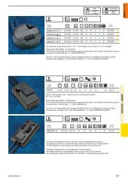
<strong>ANALOG</strong> Omega<br />
<strong>ANALOG</strong> omega<br />
<strong>Interfaccia</strong> <strong>analogica</strong><br />
Analogical interface<br />
<strong>ANALOG</strong> omega è un’interfaccia <strong>analogica</strong> che unitamente al modulo di<br />
potenza (MASTER Omega – MINIMASTER Omega – RH HIGH Omega),<br />
permette di effettuare la regolazione tramite un potenziometro, già<br />
a corredo, oppure con segnale di comando 0÷10Vcc, proveniente da<br />
PLC, computer ecc., ancora tramite il contatto di un relè passo-passo o<br />
interruttore, è possibile utilizzare le rampe di salita e discesa, per sfruttare<br />
l’effetto dissolvenza, funzione utilizzata solitamente in applicazioni come<br />
cinema e/o teatri, se ne sconsiglia l’utilizzo, in questa ultima congurazione,<br />
unitamente all’articolo JOLLY omega necessario per il comando di<br />
lampade uorescenti, poiché per le caratteristiche di costruzioni dei reattori<br />
elettronici, potrebbero vericarsi fastidiosi lampi di luce all’accensione. Sul<br />
pannello frontale sono presenti 4 manopole di regolazione da utilizzare<br />
per impostare, rispettivamente:<br />
MIN = impostazione della tensione di uscita minima<br />
MAX = impostazione della tensione di uscita massima<br />
T on = impostazione del tempo di rampa di salita (0÷60 sec.)<br />
T off = impostazione del tempo di rampa di discesa (0÷60 sec.)<br />
<strong>ANALOG</strong> omega is an <strong>analogica</strong>l interface that together with the power<br />
module (MASTER Omega – MINIMASTER Omega – RH HIGH omega),<br />
allows dimming to be carried out using a potentiometer (provided) or<br />
with a 0÷10Vcc control signal from the PLC, computer etc.. Furthermore,<br />
using a step relay or switch, it is possible to use incline or descent ramps<br />
to take advantage of the dissolving effect. This function is used only in<br />
applications such as cinemas/theatres. Do not use together with the JO-<br />
LLY omega necessary for controlling fluorescent lamps because due the<br />
characteristics of the electronic ballast, disturbing flashes of light could<br />
verify at switch on. There are 4 dimming knobs available on the front<br />
panel to be using for setting:<br />
MIN = minimum voltage output setting<br />
MAX = maximum output voltage setting<br />
T on = time setting of the incline ramp (0÷60 sec.)<br />
T off = time setting of the descent ramp (0÷60 sec.)<br />
FLUORESCENTI BARRA DIN - DIN FLUORESCENT TRACK<br />
Articolo<br />
Article<br />
Moduli<br />
Modules<br />
Alimentazione<br />
Power supply<br />
Comando<br />
Control<br />
Codice<br />
Code<br />
<strong>ANALOG</strong> omega 4 DIN 230Vac 50Hz<br />
Potenziometro - Segnale<br />
Potentiometer - Signal<br />
0÷10Vcc<br />
RN0849<br />
376 www.relco.it
<strong>ANALOG</strong> Omega<br />
DATI TECNICI - TECHNICAL DATA<br />
since 1967<br />
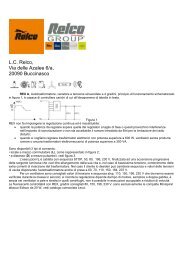
Norme per l’installazione e l’esercizio<br />
L’installazione, deve essere realizzata a regola d’arte, e da personale<br />
qualicato, è da eseguirsi seguendo scrupolosamente gli schemi di collegamento,<br />
dopo aver tolto tensione all’impianto. L’alloggiamento deve<br />
essere realizzato all’interno di un quadro elettrico e l’apparecchiatura deve<br />
essere afancata solo ed esclusivamente ai moduli di potenza indicati.<br />
La temperatura ambiente di riferimento per il corretto funzionamento, da<br />
rilevare all’interno del quadro, è pari a 35°C, la potenza dissipata, indicazione<br />
valida per entrambe le apparecchiature, è pari a 1W.<br />
Installation and use standards<br />
Installation must be carried out in compliance with laws in force and by<br />
qualified staff. Follow scrupulously the connection diagrams. After disconnecting<br />
power from the plant, The device must be placed inside the<br />
electric panel and placed at the side of the indicated power modules.<br />
The reference ambient temperature for correct functioning, to be detected<br />
inside the panel, is equal to 35°C. The dissipated power, valid for<br />
both appliances is equal to 1W.<br />
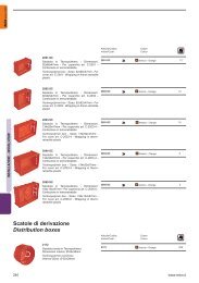
Fig. 1 - MASTER + <strong>ANALOG</strong> Omega (Comando 0÷10Vcc - Control with 0÷10Vcc<br />
signal)<br />
Fig. 2 - MASTER + <strong>ANALOG</strong> Omega (Comando con relè passo-passo - Step<br />
relay control)<br />
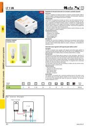
Fig. 3 - MINIMASTER + <strong>ANALOG</strong> Omega (Comando 0÷10Vcc - Control with<br />
0÷10Vcc signal)<br />
Fig. 4 - MINIMASTER + <strong>ANALOG</strong> Omega (Comando con relè passo-passo -<br />
Step relay control)<br />
FLUORESCENTI BARRA DIN - DIN FLUORESCENT TRACK<br />
www.relco.it<br />
377