flexible conduit systems - Cosmec srl
flexible conduit systems - Cosmec srl
flexible conduit systems - Cosmec srl

Create successful ePaper yourself
Turn your PDF publications into a flip-book with our unique Google optimized e-Paper software.
SISTEMI SISTEMI METALLICIMETALLIC SYSTEMS SYSTEMS
COSMEC <strong>srl</strong><br />
Costituita nel 1977, per imporsi sul mercato <strong>Cosmec</strong> s.r.l. ha dovuto sviluppare idee nuove, dimostrare dinamismo, flessibilità e soprattutto interesse nell’analizzare e risolvere<br />
le esigenze di installatori ed industrie.<br />
Leader nella produzione di sistemi per la protezione dei cavi negli impianti elettrici, <strong>Cosmec</strong> s.r.l. e’ stata la prima azienda italiana ad inserire sul mercato i sistemi metallici rigidi<br />
leggeri con continuità elettrica e tenuta stagna per impianti in ambienti a maggior rischio d’incendio, sviluppando diverse soluzioni d’impianto.<br />
Oltre alle certificazioni di prodotto già conseguite nel 1991, nell’Aprile 1999 <strong>Cosmec</strong> s.r.l. ha portato alla certificazione l’intero Sistema Aziendale secondo la norma UNI EN ISO<br />
9001.<br />
Accurati controlli in tutti i processi produttivi ed un attrezzato laboratorio interno, consentono il monitoraggio continuo degli standard qualitativi a garanzia di prodotti conformi<br />
alle normative di riferimento.<br />
La produzione della <strong>Cosmec</strong> s.r.l. avviene nello stabilimento di Villanova sull’Arda (PC) mediante macchine a controllo numerico, transfert, torni da barra, profilatrici e centri di<br />
lavoro. L’intera filiera produttiva viene gestita e monitorata tramite sistemi avanzati di raccolta dati di produzione, tracciabilità e logistica dei materiali; la superficie occupata è<br />
di 11.000 m 2 .<br />
L’organizzazione di vendita è composta da agenti plurimandatari ed opera sul mercato nazionale promuovendo i prodotti presso gli utilizzatori, mentre nelle principali nazioni<br />
europee si propone tramite distributori.<br />
SINTESI DI PRODUZIONE<br />
I sistemi SISPROEL® di <strong>Cosmec</strong> s.r.l. sono composti da tubi rigidi ricavati da lamiera zincata “Sendzimir” conformi alle Norme CEI EN 61386 e da una serie di raccordi di<br />
collegamento filettati o ad innesto rapido; è inoltre possibile realizzare l’intero sistema in acciaio INOX. Questi sistemi, assoggettati al controllo dei Marchi di Qualità IMQ e VDE,<br />
sono completati da tubi metallici flessibili ricoperti in PVC, un’ampia gamma di cassette ed innumerevoli altri accessori atti a realizzare impianti stagni fino ad IP67, con continuità<br />
elettrica garantita.<br />
Questi materiali trovano applicazione in modo particolare nel settore terziario (centri commerciali, locali di pubblico spettacolo, parcheggi auto, ecc.) e nei vari settori industriali,<br />
tra cui anche impianti di coogenerazione, centrali elettriche o nel settore chimico farmaceutico, enologico ed autostradale (gallerie).<br />
Appositamente studiate per il settore autostradale (negli impianti di illuminazione all’interno di gallerie), sono disponibili in diverse configurazioni, cassette di derivazione in<br />
alluminio, acciaio verniciato ed inox, in conformità alla Direttiva ANAS e certificate da laboratori accreditati.<br />
I sistemi di tubi flessibili in poliammide distribuiti da <strong>Cosmec</strong> s.r.l. trovano applicazione nei settori di automazione, macchine utensili e terziario; alcuni prodotti sono realizzati in<br />
conformità alla norma UNI 11170 che detta i requisiti di comportamento al fuoco, indispensabili per l’impiego nel settore ferroviario. Utilizzando i particolari raccordi ad innesto<br />
e disinnesto rapido, è possibile raggiungere una tenuta stagna IP68 (e IP69).<br />
La <strong>Cosmec</strong> s.r.l. produce inoltre una serie di attrezzature oleodinamiche e manuali, studiate per agevolare il lavoro degli installatori e dei quadristi, come la foratura dei pannelli<br />
nei quadri elettrici,la piegatura, foratura e taglio di barre di rame, l’aggraffatura dei terminali, il taglio e la foratura dei profili portanti a norme DIN, la foratura senza preforo<br />
dei canali portacavi ed altre applicazioni eseguibili su specifica del cliente.<br />
ABOUT OUR COMPANY<br />
<strong>Cosmec</strong> S.r.l. was founded in 1977 and has established its market presence by developing new ideas and demonstrating a <strong>flexible</strong>, dynamic approach and willingness to analyse and solve<br />
the special needs of installers and industry.<br />
Leader in the production of electrical installation protection <strong>systems</strong>, <strong>Cosmec</strong> S.r.l. was the first Italian company to introduce on the market light-weight rigid metal <strong>systems</strong> with high standards<br />
of electrical continuity and water tightness for areas particularly subject to fire risk, developing a range of system solutions.<br />
In addition to the product certification granted in 1991, in April 1999 the entire <strong>Cosmec</strong> S.r.l. corporate management system was UNI EN ISO 9001 certified.<br />
Meticulous control throughout the production process and its well-equipped in-house laboratory allow for constant monitoring of quality standards in order to guarantee product compliance<br />
with reference standards.<br />
The <strong>Cosmec</strong> S.r.l. production facilities are located in Villanova sull’Arda (PC) and boast numerically controlled machines, transfer machines, bar lathes, profiling machines and machining centres.<br />
The entire production process is managed and monitored using state-of-the-art <strong>systems</strong> to gather production, traceability and logistics data, within a total surface area of 11,000 sqm.<br />
<strong>Cosmec</strong>’s sales network is comprised of multifirm agents active throughout Italy who present and promote products to their clientele, while major European countries are served by a network<br />
of distributors.<br />
OUR PRODUCTS<br />
<strong>Cosmec</strong> S.r.l.’s SISPROEL® <strong>systems</strong> are comprised of rigid <strong>conduit</strong>s made from “Sendzimir” galvanised steel sheet that comply with CEI EN 61386 standards, as well as a series of<br />
threaded and quick-coupling connectors. The entire system can also be manufactured in stainless steel. These <strong>systems</strong>, subject to IMQ and VDE quality certification checks, also include PVCcoated<br />
<strong>flexible</strong> metal <strong>conduit</strong>s, a wide range of junction boxes and many other accessories used to create <strong>systems</strong> with up to an IP67 protection rating and guaranteed electrical continuity.<br />
These materials are particularly suitable for service sector applications (shopping centres, public entertainment venues, parking areas, etc.), as well as a full range of industrial applications,<br />
including cogeneration and electrical power plants, and in the chemical and pharmaceutical, wine production and highway (tunnel) sectors.<br />
It offers a range of junction boxes in aluminium, painted steel and stainless steel that have been specifically designed for highway applications (lighting inside tunnels) and conform with ANAS<br />
standards and are certified by accredited laboratories.<br />
The <strong>flexible</strong> <strong>conduit</strong> <strong>systems</strong> in polyamide offered by <strong>Cosmec</strong> S.r.l. can also be used in the automation, machine tool and rail sectors because they conform with UNI 11170 standard that<br />
provides requirements for fire protection. Utilizing their specially-designed quick-coupling connectors, water tightness with a protection rating of IP68 and IP69 may be achieved.<br />
<strong>Cosmec</strong> S.r.l. also produces a series of hydraulic and manual equipment designed to facilitate the work of installers and control panel operators, such as drilling electrical panel boards, bending,<br />
cutting and punching copper bars, seaming terminals, cutting and drilling frame profiles to DIN standards, punching cable ducts without pre-holes, as well as other applications developed on<br />
customer request.
Laboratorio prove<br />
Test Laboratory<br />
Reparto produzione<br />
Production Bay<br />
Profilatrice tubo<br />
flessibile<br />
Roll forming machine<br />
for <strong>flexible</strong> <strong>conduit</strong>s<br />
Reparto produzione<br />
Production Bay<br />
LE NOSTRE REFERENZE - OUR REFERENCES<br />
Centrali del progetto “SERENE” (Centrali di coogenerazione all’interno di cinque stabilimenti Fiat.)<br />
Centrale di coogenerazione gruppo Edison, A.E.M. Milano Bicocca, Sarmato, Terni, Jesi, Torviscosa<br />
Centrali Elettriche : La Spezia, Brindisi, Fusine, Termini Imerese,Vado Ligure, La Casella Piacenza<br />
Torvaldaliga Nord, Simeri Crichi, Rizziconi<br />
Inceneritore e Coogenerazione di Figino MI (ABB), Inceneritori Regione Campania<br />
Cementificio di Calusco (Siemens)<br />
Autostrada Messina Palermo, Palermo Catania, Galleria del Frejus, Galleria di Macerata<br />
Siti Telecom, Wind, Omnitel, galleria Monte Bianco (protezione fibre ottiche per telecomunicazioni)<br />
Centrali di desalinizzazione a Doha West & Az Zour South in Kuwait<br />
IDP Ferscalo di Pero, IDP Osmannoro (per manutenzione Treni Alta Velocità)<br />
Gallerie TAV Roma Napoli, Tronco Ferrovie Nord Milano, galleria TAV Bologna Firenze<br />
Banca d’Italia Frascati, Monte dei Paschi di Siena<br />
Basi Nato di Comiso, Capodichino, Sigonella, Aviano, Vicenza, Camp Derby, Lago Patria, Creta<br />
Fiera di Milano, Lingotto Torino, Il Portello<br />
Metropolitana di Atene, Metropolitana di Napoli, Metropolitana di Torino<br />
Aeroporti di Monaco, Bucarest, Bologna, Oporto, Malpensa 2000<br />
Settore ferroviario: Meneghino, TSR, Circumvesuviana, Vivalto<br />
Auditorium di Roma, Teatro La Fenice di Venezia, Teatro Regio di Torino, Teatro di Cortona<br />
Centri commerciali: Euromercato BO , Ipercoop Collestrada PG, Ikea Fiumara GE<br />
Nuovo stabilimento Ferrari Maranello, stabilimento Campari Novi Ligure, Iveco Torino.<br />
Cohgeneration Plants part of “SERENE” Project in FIAT building<br />
Cohgeneration Plants in: Edison group, A.E.M., Milano Bicocca, Sarmato, Terni, Jesi, Torviscosa<br />
Eklectric Plants in: La Spezia, Brindisi Fusine, Termini Imprese, Vado Ligure, La Casella Piacenza<br />
Torvaldaliga Nord, Simeri Crichi, Rizziconi<br />
Incinerator and Cohgeneration Plant in Figino (MI) ABB, Incinerators in Calabria Region<br />
Cement Mill in Calusco (SIEMENS)<br />
Highway Messina – Palermo, Palermo – Catania, Frejus Tunnel, Macerata Tunnel<br />
Telecom, Wind, Omnitel, Monte Bianco Tunnel<br />
Desalination Plant in Kwait<br />
IDP Railyard in Ferscalo, Pero (MI), IDP Railyard in Osmaronno (maintenance of High Speed Trains)<br />
TAV tunnel Roma – Napoli, Nord Railway in Milan, TAV tunnel Bologna – Firenze<br />
Banca d’Italia Frascati, Frascati office<br />
Monte dei Paschi di Siena, Siena office<br />
NATO Base of Cosimo, Capodichino, Sigonella, Aviano, Vicenza, Camp Derby, Lago Patria, Creta<br />
Milan Exhibition Building, Shopping Centre Lingotto, Turin<br />
Athens Underground, Naples Underground, Turin Underground<br />
Airports of Munchen, Bucarest, Bologna, Oporto, Malpensa 2000<br />
Railway Industry: Meneghino, TSR, Circumvesuviana, Vivalto: Italian Railway Installations<br />
Rome Auditorium, Municipal Theatre La Fenice in Venice, Municipal Theatre Regio in Turin, Municipal Theatre<br />
in Cortona Italian main Shopping Centres: EuroMarket in Bologna, Ipercoops, Ikea<br />
Ferrari’s factory in Maranello, Campari’s factory in Novi Ligure, Iveco’s factory in Turin.<br />
Magazzino automatico<br />
Automatic Warehouse<br />
Magazzino prodotto finito<br />
Endproduct Warehouse<br />
Magazzino Tubo<br />
Conduits Warehouse
SETTORI DI IMPIEGO<br />
Product Applications<br />
La realizzazione di un impianto elettrico deve essere curata in modo tale che questo non solo non sia causa d’innesco d’incendio, ma non deve<br />
costituire una via per la sua propagazione, ne dare luogo a sviluppo di gas o fumi tossici.<br />
Partendo da questo principio fondamentale a tutela della sicurezza, risulta evidente che nei locali con presenza di pubblico (es. discoteche, teatri,<br />
centri commerciali, parcheggi sotterranei, ecc.) sono da preferire materiali metallici poiché non costituiscono pericolo d’innesco e risultano assolutamente<br />
passivi di fronte alle sollecitazioni esterne.<br />
Altri luoghi in cui è preferibile utilizzare i sistemi metallici, sono quelli in cui è possibile la presenza di roditori (mulini, mangimifici, depositi di carta,<br />
archivi, falegnamerie, depuratori, ecc.) in quanto i sistemi plastici possono essere aggrediti e non offrono sufficienti garanzie di protezione ai cavi.<br />
Le norme di prodotto emesse dal CEI comprendono una vasta gamma di materiali che differiscono tra loro per caratteristiche meccaniche, elettriche<br />
o per il comportamento nei confronti delle influenze esterne.<br />
Naturalmente questi materiali pur essendo sottoposti al controllo dei Marchi IMQ e VDE, danno delle risposte diverse a seconda dei luoghi in cui<br />
vengono installati.<br />
Le norme CEI emesse dal comitato 64 che dovrebbero fornire le opportune indicazioni, disattendono questo compito lasciando al progettista l’onere<br />
della scelta dei materiali, che il più delle volte è vincolata da problemi economici e non da una ponderata considerazione dell’effettiva validità dei<br />
materiali scelti in funzione dei luoghi, del comportamento agli agenti esterni, e quindi del mantenimento degli attributi nel tempo. Infatti, nel caso di<br />
una installazione esposta al sole, è bene considerare che il PVC perde, dopo il primo anno, circa il 20% delle sue caratteristiche meccaniche e quindi<br />
non sarebbe più idoneo a svolgere il compito di protezione cavi cui era destinato.<br />
Altro esempio in cui l’uso di materiale non metallico porta ad un repentino degrado dell’impianto, si può vedere nei parcheggi multipiano, dove le tubazioni<br />
sono poste ad altezze limitate e quindi soggette ad atti vandalici, per cui non è raro vedere i tubi sfilati dai raccordi, restare appesi ai cavi.<br />
È inoltre da sfatare la complessità nell’esecuzione di un impianto metallico, poiché con i raccordi ad innesto rapido la facilità di montaggio dei componenti<br />
ne ha ridotto drasticamente tempi, rendendolo competitivo con i sistemi plastici.<br />
Concludendo, il sistema metallico è particolarmente indicato in tutte le applicazioni industriali poiché, ambienti con POTENZIALE<br />
RISCHIO DI: URTI – INTEMPERIE – MAGGIOR RISCHIO D’INCENDIO – SICUREZZA<br />
A proper electrical installation is not only designed to safeguard against the outbreak of fire, but also to prevent its spread as well as the propagation<br />
of toxic fumes or gasses.<br />
Given this fundamental safety requirement, it stands to reason that in public places (for example, discotheques, theatres, shopping centres and<br />
underground parking areas) metallic materials are preferable because there is no danger of them igniting and they are completely immune to<br />
external forces.<br />
Other areas in which metallic materials are recommended included those locations such as mills, feed storage, paper warehouses, archives or woodworking<br />
shops where plastic sheathing is subjected to rodent damage and can not guarantee adequate wire protection.<br />
Product standards issued by the IEC cover a wide range of materials that differs in terms of their mechanical and electrical characteristics and offer<br />
different performance levels in the face of external factors.<br />
Of course these materials, subjected to IMQ and VDE controls, will perform differently depending on where they are installed.<br />
Although the IEC standards issued by the Committee 64 should provide the relevant guidelines, they do not fulfil this task and leave the choice of<br />
materials to the discretion of the technical designer who is often more concerned with economic constraints than selecting the proper materials to be<br />
utilized on the basis of the site, external factors and maintenance of product characteristics over time.<br />
For example, in a PVC installation exposed to the rays of the sun, the plastic material loses approximately 20% of its mechanical properties in the<br />
first year, making it inadequate to provide the wire protection for which it was intended. Another example in which the use of non metallic material<br />
leads to a rapid deterioration of the installation can be found in public parking areas in which <strong>conduit</strong>s are positioned at low heights where they are<br />
subjected to acts of vandalism and therefore, it is not uncommon to see sheaths pulled out of the connectors while still hanging to the wires.<br />
In addition metallic <strong>systems</strong> are no longer complicated to install thanks to the new quick-couplers that greatly reduce installation time, making them<br />
competitive with plastic <strong>systems</strong>.<br />
Finally, the Metallic System is particularly suitable in all the industrial applications, because they are environments with a<br />
higher percent of risk: BUMP ACCIDENTS – BED WEATHER – FIRE – SAFETY<br />
3
SETTORI DI IMPIEGO<br />
Product Applications<br />
TERZIARIO – LOCALI DI GRANDE AFFOLLAMENTO SERVICE INDUSTRIES – CROWDED PUBLIC PLACES<br />
Alberghi e ristoranti Hotels and Restaurants<br />
.....................<br />
Mostre ed esposizioni Exhibition Areas<br />
Banche Banks<br />
Strutture didattiche Schools<br />
Centri commerciali Shopping Centres<br />
Stadi ed impianti sportivi Sports Stadium<br />
Centrali termiche Power Plants<br />
Parcheggi pubblici Public parking<br />
Stazioni ed aeroporti Railway Stations and airports<br />
Ospedali e ricoveri Hospitals<br />
Caserme e carceri Prisons and Barracks<br />
Ambienti di rilevanza storica artistica Historical and Artistic places<br />
INDUSTRIALE INDUSTRIAL<br />
Officine meccaniche Mechanical Workshops<br />
Garage Parking garages<br />
Lavanderie Laundries<br />
Fabbriche e magazzini tessili Textile Factories and warehouses<br />
Stabilimenti siderurgici Ironworks<br />
CHIMICO FARMACEUTICA CHEMICAL AND PHARMACEUTICAL INDUSTRY<br />
ALIMENTARE FOOD INDUSTRY<br />
Lavorazione alimenti Food Processing<br />
Cantine Wine cellars<br />
Caseifici Cheese Factory<br />
PRODUZIONE ENERGIA ENERGY PRODUCTION<br />
INFRASTRUTTURE INFRASTRUCTURE<br />
Ferrovie Railway Lines<br />
Depuratori Cleaners<br />
Metropolitane Undergrounds<br />
Discariche Garbage Dumps<br />
Autostrade Highways<br />
BORDO MACCHINA INSTALLED ON MACHINES<br />
Macchine utensili Machine Tools<br />
Macchine tipografiche Printing Machines<br />
Macchine per imballaggio Packing Machines<br />
Macchine da stampaggio Press Machines<br />
Lavorazione legno Wood Processing<br />
Caldaie Boilers<br />
Lavorazione marmo Marble Processing<br />
FERROVIARIO RAILWAY INDUSTRY<br />
Carrozze Coaches<br />
Locomotori Locomotives<br />
Segnalamento Signalling<br />
.....................<br />
.....................<br />
.............<br />
.....................<br />
.....................<br />
.....................<br />
.....................<br />
.....................<br />
.............................................. .......... .................. ........................... ..........<br />
.............<br />
.............<br />
.............<br />
.....................<br />
.............<br />
.....................<br />
RISCHI AGGIUNTIVI MORE RISKS<br />
ATTI VANDALICI HUMAN VANDALIC ACTIONS<br />
EVACUAZIONE EVACUATION<br />
AMBIENTE AGGRESSIVO DANGEROUS ENVIRONMENT<br />
DEPERIMENTO CARATTERISTICHE MATERIALI QUALITY MATERIAL DECLINE<br />
CONTAMINAZIONE ALIMENTI FOOD POLLUTION<br />
POLVERI ESPLOSIVE EXPLOSIVE POWDER<br />
RODITORI RODENT DAMAGES<br />
POLVERI ESPLOSIVE EXPLOSIVE POWDER<br />
SOLLECITAZIONI MECCANICHE MECHANICAL TREMBLING<br />
ATTI VANDALICI HUMAN VANDALIC ACTIONS<br />
EVACUAZIONE EVACUATION<br />
SOLLECITAZIONI MECCANICHE MECHANICAL TREMBLING<br />
SOLLECITAZIONI MECCANICHE MECHANICAL TREMBLING<br />
INTERFERENZE ELETTROMAGNETICHE ELECTROMAGNETIC INTERFERENCES<br />
MARINO MARITIME INDUSTRY<br />
AMBIENTE AGGRESSIVO DANGEROUS ENVIRONMENT<br />
4
PRESENTAZIONE AZIENDALE . ABOUT OUR COMPANY.................................................................................. P. 1<br />
TABELLE, LEGENDE, CERTIFICAZIONI E RIFERIMENTI NORMATIVI ...................................................... P. 7<br />
TABLES, EXPLANATORY NOTES, CERTIFICATIONS AND REFERENCE STANDARDS<br />
1<br />
SISTEMA TUBI FLESSIBILI<br />
FLEXIBLE CONDUIT SYSTEMS<br />
TUBI METALLICI . METAL CONDUITS<br />
-SEMPLICE AGGRAFFATURA................................................................................................. P. 13<br />
SIMPLE INTERLOCKING<br />
- DOPPIA AGGRAFFATURA................................................................................................... P. 21<br />
DOUBLE INTERLOCKING<br />
- PIEGHEVOLI......................................................................................................................... P. 23<br />
BENDABLE CONDUITS<br />
TUBI IN PVC . PVC CONDUITS<br />
- LISCIO................................................................................................................................... P. 24<br />
SMOOTH<br />
- SPIRALATO.......................................................................................................................... P. 26<br />
HELICAL<br />
RACCORDI . CONNECTORS<br />
- PER TUBI METALLICI FLESSIBILI E PIEGHEVOLI............................................................... P. 28<br />
FOR FLEXIBLE AND BENDABLE METAL CONDUITS<br />
- PER TUBI IN PVC FLESSIBILI.............................................................................................. P. 33<br />
FOR PVC FLEXIBLE CONDUITS<br />
ACCESSORI . ACCESSORIES<br />
- FASCETTE METALLICHE STRINGITUBO.............................................................................. P. 35<br />
METAL CLAMPS<br />
- BOCCOLE PER TUBI FLESSIBILI PRIVI DI RIVESTIMENTO.............................................. P. 35<br />
KIT FOR FLEXIBLE CONDUITS WITHOUT COATING<br />
- KIT DI SERRAGGIO TRECCIA.............................................................................................. P. 36<br />
BRAID GRIPPING KIT<br />
INDICE INDEX<br />
2<br />
3<br />
SISTEMA TUBI RIGIDI<br />
RIGID CONDUIT SYSTEMS<br />
ELEMENTI DI FISSAGGIO<br />
FASTENING COMPONENTS<br />
TUBI METALLICI . METAL CONDUITS<br />
- IN ACCIAIO ZINCATO.......................................................................................................... P. 37<br />
GALVANISED STEEL<br />
- IN ACCIAIO INOX................................................................................................................ P. 39<br />
STAINLESS STEEL<br />
RACCORDI . CONNECTORS<br />
- BREVETTATI AD INNESTO RAPIDO IN OTTONE NICHELATO.......................................... P. 40<br />
PATENTED QUICK-COUPLING CONNECTORS IN NICKEL PLATED BRASS<br />
- BREVETTATI AD INNESTO RAPIDO IN ACCIAIO INOX.................................................... P. 43<br />
PATENTED QUICK-COUPLING CONNECTORS IN STAINLESS STEEL<br />
- MANICOTTI FILETTATI......................................................................................................... P. 44<br />
THREADED COUPLINGS<br />
ACCESSORI . ACCESSORIES<br />
- CURVE A 90°NON FILETTABILI.......................................................................................... P. 45<br />
90° NON-THREADABLE ELBOWS<br />
- TESTACANNA....................................................................................................................... P. 46<br />
BUSHINGS<br />
IN ACCIAIO ZINCATO . GALVANISED STEEL............................................................................... P. 47<br />
IN ACCIAIO INOX . STAINLESS STEEL....................................................................................... P. 50<br />
5
4<br />
5<br />
6<br />
PRESSACAVI<br />
GLANDS<br />
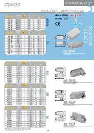
SCATOLE<br />
BOXES<br />
ACCESSORI<br />
ACCESSORIES<br />
IN OTTONE NICHELATO . NICKEL PLATED BRASS..................................................................... P. 51<br />
IN OTTONE NICHELATO - ATEX . ATEX CERTIFICATION ..........................................................P. 53<br />
IN ACCIAIO INOX . STAINLESS STEEL ...................................................................................... P. 54<br />
IN POLIAMMIDE . POLYAMIDE................................................................................................ P. 55<br />
DI INFILAGGIO IN LEGA DI ALLUMINIO . ALUMINIUM ALLOY FEEDER BOXES.........................P. 56<br />
DI DERIVAZIONE IN LEGA DI ALLUMINIO, STANDARD E ATEX...................................... P. 59<br />
ALUMINIUM ALLOY JUNCTION BOXES AND ATEX CERTIFICATION<br />
DI DERIVAZIONE E PULSANTIERE INOX . JUNCTION BOXES AND PUSH BUTTON PANELS......... P. 63<br />
PER TUNNEL . SPECIAL BOXES FOR TUNNELS............................................................................. P. 64<br />
ACCESSORI PER SCATOLE DI DERIVAZIONE .................................................................... P. 70<br />
ACCESSORIES FOR ALUMINIUM ALLOY JUNCTION BOXES<br />
MANICOTTI-TAPPI-NIPPLI . COUPLINGS-PLUGS-NIPPLES......................................................... P. 71<br />
RACCORDI CURVI . ELBOW CONNECTORS............................................................................... P. 72<br />
RIDUZIONI . REDUCERS.......................................................................................................... P. 73<br />
GHIERE . RING NUTS................................................................................................................ P. 76<br />
GUARNIZIONI . SEALS...........................................................................................................P. 78<br />
7<br />
ATTREZZATURE PER INSTALLATORI<br />
EQUIPMENT FOR INSTALLERS<br />
CURVATUBI . CONDUIT BENDING MACHINE.................................................................................P. 79<br />
FORACANALE . DUCT PIERCER................................................................................................. P. 82<br />
ESEMPI DI DERIVAZIONE . JUNCTION EXAMPLES........................................................................................... P. 83<br />
ESEMPI DI IMPIANTI . INSTALLATION EXAMPLES............................................................................................. P. 85<br />
FORZA COMMERCIALE . COSMEC SALES NETWORK........................................................................................ P. 87<br />
6<br />
INDICE INDEX
1° CIFRA<br />
Resistenza<br />
alla<br />
compressione<br />
Resistance<br />
to<br />
compression<br />
CLASSIFICAZIONE DEI SISTEMI COSMEC secondo le norme CEI EN 61386 - Classification in compliance with the IEC 61386 standards<br />
2° CIFRA<br />
Resistenza<br />
all’urto<br />
Resistance<br />
to impact<br />
3° CIFRA<br />
Temperatura<br />
minima di<br />
utilizzo<br />
Lower<br />
temperature<br />
range<br />
4° CIFRA<br />
Temperatura<br />
massima di<br />
utilizzo<br />
Upper<br />
temperature<br />
range<br />
5° CIFRA<br />
Resistenza<br />
alla<br />
curvatura<br />
Resistance to<br />
bending<br />
6° CIFRA<br />
Caratteristiche<br />
elettriche<br />
Electrical<br />
characteristics<br />
7° CIFRA<br />
Protezione ai<br />
solidi<br />
Protection<br />
against solids<br />
8° CIFRA<br />
Protezione<br />
all’acqua<br />
Protection<br />
against liquids<br />
9° CIFRA<br />
Resistenza<br />
alla<br />
corrosione<br />
Resistance<br />
against<br />
corrosion<br />
10° CIFRA<br />
Resistenza<br />
alla trazione<br />
Tensile<br />
strength<br />
11° CIFRA<br />
Resistenza<br />
alla propag.<br />
della fiamma<br />
Resistance<br />
to flame<br />
propagation<br />
667M 3 3 5 6 4 1 4 0 2 3 1 4<br />
6070 3 4 3 1 4 3 6 7 2 3 1 4<br />
607E 3 4 4 1 4 3 6 7 2 3 1 4<br />
607ETX 3 4 4 1 4 3 4 4 4 3 1 4<br />
6071 3 4 3 1 4 3 4 4 2 3 1 4<br />
6071T 3 4 3 1 4 1 4 4 2 3 1 4<br />
6071E 3 4 4 1 4 1 4 4 2 3 1 4<br />
6071ET 3 4 4 1 4 1 4 4 2 3 1 4<br />
6071ETX 3 4 4 1 4 1 4 4 4 3 1 4<br />
667DM 4 4 5 6 4 1 4 0 2 4 1 4<br />
607D 4 4 3 1 4 3 6 7 2 4 1 4<br />
607X 5 5 5 7 2 1 6 7 4 5 1 5<br />
6085 0 2 3 1 4 2 6 7 / 0 1 0<br />
6089 0 2 3 1 4 2 6 7 / 0 1 0<br />
6080 1 3 1 1 4 2 6 5 / 0 1 0<br />
6079 2 3 1 1 4 2 6 5 / 0 1 0<br />
6008-L 5 5 4 5 1 1 6 7 2 4 1 4<br />
6008-P 5 5 4 5 1 1 6 7 2 4 1 4<br />
6700 5 5 4 5 1 1 6 7 4 4 1 4<br />
12° CIFRA<br />
Resistenza al<br />
carico sospeso<br />
Suspended<br />
load capacity<br />
La classificazione si intende per il sistema di protezione<br />
tubo-raccordo. I codici vengono assegnati come valore minimo<br />
valido per tutta la serie di misure, per alcuni articoli<br />
pertanto, i valori effettivi potrebbero risultare superiori<br />
a quanto indicato in tabella. Per maggiori informazioni<br />
consultare le pagine specifiche del prodotto o contattare il<br />
nostro ufficio tecnico al n° (+39) 0523 837825.<br />
Grado di protezione agli agenti esterni e temperature di<br />
esercizio sono indubbiamente caratteristiche fondamentali<br />
nei sistemi di protezione. Per agevolare l’individuazione<br />
del sistema più idoneo ad una specifica applicazione, nella<br />
tabella seguente sono indicati i valori delle soluzioni proposte<br />
da COSMEC.<br />
Classification refers to the <strong>conduit</strong>/fitting protection system.<br />
The codes are assigned as the minimum value valid for the<br />
entire series of measurements; therefore, for some items, the<br />
actual values could be higher than those given in the table. For<br />
further information, please refer to the specific product pages<br />
or contact our engineering office at (+39) 0523/837581.<br />
The protection level against external agents and working temperatures<br />
are unquestionably basic characteristics of protection<br />
<strong>systems</strong>. To facilitate identification of the most suitable system<br />
for a given application, the table below provides the values for<br />
the solutions proposed by COSMEC.<br />
Gradi di Protezione IP e temperature di esercizio °C dei Sistemi <strong>Cosmec</strong> - IP Protection level and working temperatures of <strong>Cosmec</strong> Systems<br />
RIFERIMENTI NORMATIVI<br />
Normative References<br />
IP40 IP44 IP65 IP67<br />
667M<br />
6070<br />
607E<br />
607ETX<br />
6071<br />
6071T<br />
6071E<br />
6071ET<br />
6071ETX<br />
667DM<br />
607D<br />
607X<br />
6085<br />
6089<br />
6080<br />
6079<br />
6008L<br />
6008P<br />
6700<br />
-45 -25 -15 -5 0 +5 +25 +45 +60 +70 +90 +110 +130 +150 +250<br />
7
Riferimenti normativi<br />
CEI EN 61386<br />
Sistemi di tubi e accessori per installazioni<br />
elettriche<br />
Dal giugno 2005 sostituisce la norma CEI EN 50086 e specifica<br />
le prescrizioni e le prove applicabili ai sistemi di tubi<br />
e accessori, destinati alla protezione e all’installazione dei<br />
conduttori isolati e/o dei cavi negli impianti elettrici o nei<br />
sistemi di telecomunicazione fino a 1000 V c.a. e/o fino<br />
a 1500V c.c.. Si applica ai sistemi di tubi e accessori metallici,<br />
non metallici e composti con le estremità filettate e<br />
non filettate. Non si applica agli involucri ed alle scatole di<br />
connessione che sono oggetto della IEC 60670.<br />
La norma prevede che il sistema venga classificato in base<br />
alle proprietà dichiarate, tramite una serie di codici riferiti<br />
alle caratteristiche meccaniche, termiche ed elettriche.<br />
Normative references<br />
IEC 61386 Standard<br />
Conduit <strong>systems</strong> for electrical installations<br />
From june 2005 it replaces EN 50086 standard and specifies<br />
requirements and tests for <strong>conduit</strong> <strong>systems</strong>, including <strong>conduit</strong>s<br />
and <strong>conduit</strong> fitting, for the protection and management of<br />
insulated conductors and7or cables in electrical installation or<br />
in communication <strong>systems</strong> up to 1000 V c.a. and/or 1500V<br />
d.c.. This standard applies to metallic, non-metallic and composite<br />
<strong>conduit</strong> <strong>systems</strong>, including threaded and non-threaded<br />
entries which terminate the system. This standard does not<br />
apply to enclosures and connecting boxes which come within<br />
the scope of IEC 60670.<br />
The standard previews that the system is classified based on<br />
the declared property, through a classification coding format,<br />
reported to the mechanical, thermal characteristics and electrical<br />
workers.<br />
CODICI DI CLASSIFICAZIONE secondo le norme CEI EN 61386 - CLASSIFICATION CODING in compliance with IEC 61386 standards<br />
1°cifra Resistenza alla compressione<br />
Resistance to compression<br />
2°cifra Resistenza all’urto<br />
Resistance to impact<br />
3°cifra Temperatura min. di utilizzo<br />
Lower temperature range<br />
4°cifra Temperatura max di utilizzo<br />
Upper temperature range<br />
5°cifra Resistenza alla curvatura<br />
Resistance to bending<br />
6°cifra Caratteristiche elettriche<br />
Electrical characteristic<br />
7°cifra<br />
8°cifra<br />
Protezione ai solidi<br />
Protection against solids<br />
Protezione all’acqua<br />
Protection against liquids<br />
9°cifra Resistenza alla corrosione<br />
Resistance against corrosion<br />
10°cifra Resistenza alla trazione<br />
Tensile strength<br />
11°cifra Resistenza alla propag. della fiamma<br />
Resistance to flame propagation<br />
12°cifra Resistenza al carico sospeso<br />
Suspended load capacity<br />
0 1 2 3 4 5 6 7<br />
N.D.<br />
N.D.<br />
N.D.<br />
N.D.<br />
Cerificati di Approvazione dei sistemi <strong>Cosmec</strong><br />
molto leggero<br />
very light<br />
125 N<br />
molto leggero<br />
very light<br />
0,5 J<br />
leggero<br />
light<br />
320 N<br />
leggero<br />
light<br />
1 J<br />
medio<br />
medium<br />
750 N<br />
medio<br />
medium<br />
2 J<br />
pesante<br />
heavy<br />
1250 N<br />
pesante<br />
heavy<br />
6 J<br />
molto<br />
pesante<br />
very heavy<br />
4000 N<br />
molto<br />
pesante<br />
very heavy<br />
20 J<br />
+5°C - 5°C -15°C - 25°C - 45°C<br />
+60°C +90°C +105°C +120°C +150°C +250°C +400°C<br />
rigido<br />
rigid<br />
con continuità<br />
with continuity<br />
gocce verticali<br />
vertical<br />
dropleds<br />
debole int./<br />
est.<br />
low ins./out.<br />
molto leggero<br />
very light<br />
100 N<br />
non<br />
propagante<br />
non flammable<br />
molto leggero<br />
very light<br />
20 N<br />
pieghevole<br />
pliable<br />
con isolamento<br />
with insulating<br />
gocce inclinate<br />
angled<br />
dropleds<br />
media int./est.<br />
medium ins./<br />
out.<br />
leggero<br />
light<br />
250 N<br />
propagante<br />
inflammable<br />
leggero<br />
light<br />
30 N<br />
autorinvenente<br />
self-recovering<br />
continuità ed<br />
isolamento<br />
with continuity and<br />
insulating<br />
solidi > Ø 2,5 mm<br />
objects > Ø 2,5 mm<br />
pioggia<br />
sprays<br />
media int./ alta est.<br />
medium ins. / high<br />
out.<br />
medio<br />
medium<br />
500 N<br />
medio<br />
medium<br />
150 N<br />
Approval certificates of <strong>Cosmec</strong>’s <strong>systems</strong><br />
8<br />
flessibile<br />
<strong>flexible</strong><br />
solidi > Ø<br />
1 mm<br />
object > Ø<br />
1 mm<br />
spruzzi<br />
splashed<br />
alta int. / est.<br />
high ins. / out.<br />
pesante<br />
heavy<br />
1000 N<br />
pesante<br />
heavy<br />
450 N<br />
polvere<br />
dust<br />
getti<br />
jets<br />
molto<br />
pesante<br />
very heavy<br />
2500 N<br />
molto<br />
pesante<br />
very heavy<br />
850 N<br />
totalmente<br />
protetto<br />
dust-tight<br />
getti potenti<br />
powerfull jets<br />
immersione<br />
immersion<br />
RIFERIMENTI NORMATIVI<br />
Normative References
CEI EN 60423<br />
Tubi per installazioni elettriche<br />
Diametri esterni dei tubi per installazioni elettriche e filettature<br />
per tubi ed accessori<br />
La presente norma internazionale specifica i diametri<br />
esterni dei tubi usati nelle installazioni elettriche e le prescrizioni<br />
dimensionali delle filettature nei tubi e relativi<br />
accessori.<br />
L’unica filettatura ammessa è di tipo metrico ISO 68, pertanto<br />
solamente i sistemi rispondenti a questa prescrizione<br />
risultano conformi alla norma di prodotto CEI EN 61386.<br />
CEI EN 50262<br />
Pressacavo metrici per installazioni elettriche<br />
La presente norma fornisce le prescrizioni e le prove relative<br />
alla costruzione ed alla prestazione dei pressacavo<br />
metrici per cavi elettrici. La norma si riferisce ai pressacavo<br />
completi allo stato di consegna da parte del costruttore o<br />
fornitore e non ai loro singoli componenti.<br />
Per le applicazioni in “Aree pericolose” è opportuno considerare<br />
le prescrizioni supplementari previste per tali condizioni,<br />
per es. come specificato nella EN 50014.<br />
CEI EN 60670 - CEI 23-48<br />
Scatole e involucri per apparecchi elettrici per<br />
installazioni elettriche fisse per usi domestici e<br />
similari<br />
La presente parte della IEC 60670 si applica alle scatole,<br />
agli involucri o a parti di involucri con tensione nominale<br />
non superiore a 1000 V in c.a. e a 1500 V in c.c., destinati<br />
ad installazioni elettriche fisse per usi domestici e similari,<br />
per interni o per esterni. Essa è destinata ad essere applicata<br />
alle scatole e agli involucri per apparecchi elettrici<br />
compresi nel campo di applicazione del Comitato Tecnico<br />
23. Sostituisce parzialmente la Norma CEI 23-48:1998 che<br />
rimane in vigore fino a completa integrazione con le parti<br />
seconde della presente norma.<br />
IEC 423 Standard<br />
Conduits for electrical installations<br />
Outside diameters of <strong>conduit</strong>s for electrical installations and<br />
threads for <strong>conduit</strong>s and fittings.<br />
This International Standard specifies outside diameters of <strong>conduit</strong>s<br />
used in electrical installations and the dimensional requirements<br />
for threads in the <strong>conduit</strong>s and in associated fittings.<br />
The only admitted thread is of metric type ISO 68, therefore<br />
only the <strong>systems</strong> answering to this prescription turn out consistent<br />
to the IEC 61386 standard.<br />
EN 50262<br />
Metric cable glands for electrical installations<br />
This European standard provides requirements and tests for<br />
the construction and performance of metric cable glands. This<br />
standard covers complete glands as supplied by the manufacturer<br />
or supplier, but not parts of cable glands.<br />
For the applications in “previewed additional dangerous Areas”<br />
it is opportune to consider the prescription for such conditions,<br />
for ex. as specified in EN 50014 standard.<br />
IEC 60670 - CEI 23-48 Standards<br />
Boxes and enclosures for electrical accessories for household<br />
and similar fixed electrical installations<br />
This part of IEC 60670 applies to boxes, enclosures and parts<br />
of enclosures for electrical accessories with a rated voltage not<br />
exceeding 1000 V a.c. and 1500 V d.c. intended for household<br />
or similar fixed electrical installations, either indoors or<br />
outdoors. This International standard in intended to apply to<br />
boxes and enclosure for electrical accessories within the scope<br />
of IEC technical committee 23.<br />
It partially replaces the CEI 23-48:1998 standard that is still<br />
in force until the complete integration with the second part of<br />
this standard.<br />
RIFERIMENTI NORMATIVI<br />
Normative References<br />
COMPATIBILITÀ ELETTROMAGNETICA<br />
La Compatibilità Elettromagnetica (EMC) valuta i disturbi<br />
elettromagnetici generati da tutte le apparecchiature<br />
elettriche ed elettroniche (emissioni), nonché, eventuali<br />
malfunzionamenti delle stesse, causati da perturbazioni<br />
generate da altre sorgenti di disturbo (immunità). Essa si<br />
applica anche agli impianti e alle installazioni che contengono<br />
apparecchiature e componenti elettrici e/o elettronici<br />
(anche montati a bordo di macchine).<br />
Negli ultimi anni la compatibilità elettromagnetica (EMC)<br />
ha acquisito un ruolo fondamentale nelle fasi di progettazione<br />
e di gestione in molteplici settori industriali: la<br />
trasmissione e la distribuzione di energia elettrica; l’automazione<br />
e il controllo dei processi industriali; il trasporto<br />
aereo, terrestre, navale e ferroviario; le telecomunicazioni;<br />
i macchinari elettromedicali. L’uso sempre più spinto<br />
di apparati elettrici ed elettronici, infatti, richiede la caratterizzazione<br />
dell’ambiente elettromagnetico al fine di<br />
eliminare o circoscrivere fenomeni di interferenza, i quali<br />
possono dare origine a malfunzionamenti temporanei o<br />
permanenti.<br />
Come previsto dalle normative CEI EN 61386, tutti i nostri<br />
sistemi di protezione risultano passivi rispetto alle influenze<br />
elettromagnetiche(emissioni ed immunità). Sicuri<br />
di fornire informazioni utili alla progettazione, abbiamo<br />
sottoposto i nostri sistemi ad ulteriori prove per verificarne<br />
le prestazioni in termini di efficienza di schermatura.<br />
Non essendo disponibile una normativa di riferimento specifica<br />
per la misura dell’efficienza di schermatura per<br />
9<br />
ELECTROMAGNETIC COMPATIBILITY<br />
Electromagnetic Compatibility (EMC) evaluates the electromagnetic<br />
disturbances generated by all electrical and electronic<br />
equipment (emissions), as well as any malfunctioning of the<br />
same equipment caused by interference generated by other<br />
sources of disturbance (immunity). This also applies to <strong>systems</strong><br />
and installations containing electrical and/or electronic<br />
equipment and components (including those assembled on<br />
machinery).<br />
In recent years, electromagnetic compatibility (EMC) has taken<br />
on a fundamental role in the design and management phases<br />
of many industrial sectors: electrical power transmission and<br />
distribution; automation and control of industrial processes;<br />
air, land, ship and rail transport; telecommunications; electromedical<br />
equipment. In fact, the increasingly intensive use of<br />
electrical and electronic equipment requires characterization of<br />
the electromagnetic environment to eliminate or circumscribe<br />
interference which can cause temporary or permanent malfunctioning.<br />
As specified in CEI EN 61386 standards, all our protection<br />
<strong>systems</strong> are passive in terms of electromagnetic influences<br />
(emissions and immunity). In order to provide information<br />
useful for planning purposes, our <strong>systems</strong> have undergone<br />
further testing to verify their shielding performance.<br />
Given the lack of a reference standard for measuring shielding<br />
efficiency for <strong>conduit</strong> sheathing used as shielding for generic<br />
bundled wires, for this testing the methodology proposed in<br />
IEC standard TS61587 – Mechanical structures for electronic<br />
equipment - Test for IEC 60917 and 60297. Part 3: Electro
involucri tubolari da utilizzarsi come schermature per fasci<br />
generici di conduttori, per lo svolgimento dell’attività si è<br />
adottata la metodologia proposta dalla norma IEC TS61587<br />
- Mechanical structures for electronic equipment – Test for<br />
IEC 60917 and 60297. Part 3: Electromagnetic shielding<br />
performance tests for cabinets, rack and sub-racks).<br />
magnetic shielding performance tests for cabinets, rack and<br />
sub-racks was adopted.<br />
Camera Anecoica<br />
Anechoic Chamber<br />
CEI EN 60529<br />
Gradi di protezione degli involucri (Codice IP)<br />
La Norma stabilisce un sistema di classificazione dei gradi<br />
di protezione degli involucri per materiale elettrico la cui<br />
tensione nominale non supera 72,5 kV.<br />
Il codice IP identifica i gradi di protezione di un involucro<br />
mediante la combinazione di due cifre:la prima cifra indica<br />
la protezione contro l’accesso a parti pericolose e la penetrazione<br />
di corpi solidi estranei, la seconda cifra contro<br />
l’ingresso di acqua.<br />
IEC 529 Standard<br />
Degrees of protection provided by enclosures (IP Code)<br />
This standard applies to the classification of degrees of protection<br />
provided by enclosures for electrical equipment with a<br />
rated voltage not exceeding 72,5kV.<br />
IP code is a coding system to indicate the degrees of protection<br />
provided by an enclosure by means of two figure number:<br />
the first figure indicates protection against access to hazardous<br />
parts and ingress of solid foreign objects, the second figure<br />
against ingress of water.<br />
0<br />
1<br />
2<br />
3<br />
4<br />
5<br />
6<br />
Prima cifra caratteristica (penetrazione corpi solidi)<br />
First characteristic numeral (solid foreign objects)<br />
Nessuna protezione<br />
Non-protected<br />
Protetto contro i corpi solidi superiori a<br />
50mm.(Protetto contro contatti accidentali)<br />
Protected against solid foreign objects of 50mmØ and greater.<br />
(Protection against accidental contact)<br />
Protetto contro i corpi solidi superiori a 12,5mm.<br />
(Protetto contro contatti con un dito)<br />
Protected against solid foreign objects of 12,5mmØ and<br />
greater. (Protection against contact with a finger)<br />
Protetto contro i corpi solidi superiori a<br />
2,5mm.(Protetto contro contatti con utensili)<br />
Protected against solid foreign objects of 2,5mmØ and<br />
greater. (Protection against contact with a tools)<br />
Protetto contro i corpi solidi superiori a<br />
1mm.(Protetto contro contatti con un filo)<br />
Protected against solid foreign objects of 1mmØ and greater.<br />
(Protection against contact with a wire)<br />
Protetto contro la polvere, nessun deposito nocivo<br />
Dust-protected<br />
Totalmente protetto contro la polvere<br />
Dust-tight<br />
10<br />
0<br />
1<br />
2<br />
3<br />
4<br />
5<br />
6<br />
7<br />
8<br />
Seconda cifra caratteristica (ingresso di acqua)<br />
Second characteristic numeral (ingress of water)<br />
Nessuna protezione<br />
Non-protected<br />
Protetto contro la caduta verticale di gocce d’acqua<br />
Protected against vertically falling water drops<br />
Protetto contro la caduta verticale di gocce d’acqua con<br />
un’inclinazione dell’involucro fino a 15°<br />
Protected against vertically falling water drops when enclosure<br />
tilted up to 15°<br />
Protetto contro la pioggia fino a 60° dalla verticale<br />
Protected against spraying water at an angle up to 60° of<br />
the vertical<br />
Protetto contro spruzzi d’acqua da tutte le direzioni<br />
Protected against splashing water from any direction<br />
Protetto contro i getti d’acqua<br />
Protected against water jets<br />
Protetto contro le ondate ed i getti d’acqua potenti<br />
Protected against powerful water jets and waves<br />
Protetto contro gli effetti dell’immersione temporanea<br />
Protected against the effects of temporary immersion in water<br />
Protetto contro gli effetti dell’immersione continua<br />
Protected against the effects of continuous immersion in water<br />
RIFERIMENTI NORMATIVI<br />
Normative References
CEI EN 50102<br />
Gradi di protezione degli involucri per apparecchiature<br />
elettriche contro impatti meccanici esterni<br />
(Codice IK)<br />
La presente norma fornisce un sistema per la classificazione<br />
dei gradi di protezione degli involucri per apparecchiature<br />
elettriche contro impatti meccanici esterni. L’adozione,<br />
quando possibile, del sistema di classificazione considerato,<br />
favorisce l’uniformità dei metodi di descrizione della protezione<br />
fornita dagli involucri e nelle prove per la verifica dei<br />
vari gradi di protezione (IK).<br />
EN 50102<br />
Degrees of protection provided by enclosures for electrical<br />
equipment against external mechanical impacts (IK code)<br />
This standard describe a system for classifying the degrees<br />
of protection provided by enclosures for electrical equipment<br />
against external mechanical impacts. The adoption of this<br />
classification system, wherever possible, should promote uniformity<br />
in methods of describing the protection provided by<br />
the enclosure and in tests that prove different degrees of<br />
protection (IK code).<br />
Codice IK<br />
IK code<br />
Energia di impatto in Joule<br />
Impact energy in Joule<br />
IK 00 IK 01 IK 02 IK 03 IK 04 IK 05 IK 06 IK 07 IK 08 IK 09 IK 10<br />
/ 0,15 0,2 0,35 0,5 0,7 1 2 5 10 20<br />
UNI CEI EN 11170-3:2005<br />
Veicoli ferrotranviari<br />
Linee guida per la protezione al fuoco dei veicoli ferrontranviari<br />
ed a guida guidata. Valutazione del comportamento<br />
al fuoco dei materiali. Limiti di accettabilità.<br />
ALTRI RIFERIMENTI<br />
Norme riferite al comportamento dei cavi che presentano<br />
una resistenza intrinseca al fuoco, sono utilizzate come<br />
riferimento per la conduzione delle prove di verifica<br />
dell’integrità funzionale nelle scatole di derivazione per<br />
applicazioni nelle gallerie, come previsto nel Documento<br />
A.N.A.S. “Linee Guida per la progettazione della sicurezza<br />
nelle gallerie stradali”.<br />
NF C 32-070<br />
Conduttori e cavi isolati per installazioni<br />
Prove per la classificazione rispetto il comportamento al<br />
fuoco.<br />
CEI EN 50362<br />
Metodo di prova per la resistenza al fuoco di cavi per energia<br />
e comando di grosse dimensioni (con diametro esterno<br />
superiore a 20 mm) non protetti per l’uso in circuiti di<br />
emergenza<br />
CEI EN 11170-3:2005<br />
Railway and tramway vehicles.<br />
Guidelines for fire protection of railway, tramway and guided<br />
path vehicles. Evaluation of fire behaviour of materials. Limits<br />
of acceptance.<br />
OTHER REFERENCES<br />
Standards pertaining to the behaviour of cables with intrinsic<br />
flame resistance are utilized as a reference for performing<br />
tests verifying the functional integrity of junction boxes for<br />
use in tunnels, as provided for in the ANAS design guidelines<br />
for road tunnel safety, “Linee Guida per la progettazione della<br />
sicurezza nelle gallerie stradali”.<br />
NF C 32 – 070<br />
Insulated <strong>conduit</strong>s and cables for installations.<br />
Tests for the performance level results under risk of fire.<br />
CEI EN 50362<br />
Fire-resistance test method for power and control cables of<br />
large size (external diameter greater than 20 mm) and unprotected<br />
for use in emergency circuits.<br />
RIFERIMENTI NORMATIVI<br />
Normative References
AGENTI CHIMICI<br />
CHEMICAL AGENTS<br />
667M<br />
667DM<br />
6070<br />
6071<br />
607D<br />
607E<br />
6071E<br />
607ETX<br />
6071ETX<br />
6071ET 6071T 6079<br />
6080<br />
6085 6089 6008L<br />
6008P<br />
6700<br />
607X<br />
RACC. DI OTTONE<br />
NICHELATO<br />
NICKEL PLATED<br />
BRASS<br />
CONNECTORS<br />
Acetato di Vinile<br />
Vinyl Acetate<br />
Acetone<br />
Acetone<br />
Acido Acetico<br />
Acetic Acid<br />
Acido citrico<br />
Citric acid<br />
Acido cloridrico 10%<br />
Acido cloridrico 36%<br />
Hydrchloric acid<br />
(10%)<br />
Hydrchloric acid<br />
(36%)<br />
Acido Lattico<br />
Lactic Acid<br />
Acido Nitrico 10% Nitric acid (10%)<br />
Acido Nitrico 70% Nitric acid (70%)<br />
Acido Ossalico<br />
Oxalic acid<br />
Acido Solforico 10% Sulfuric acid (10%)<br />
Acido Solforico 70% Sulfuric acid (70%)<br />
Acqua di cloro<br />
Acqua di Mare<br />
Acqua<br />
ossigenata 35%<br />
Acquaragia<br />
Alcool Etilico<br />
Alcool Metilico<br />
Benzene<br />
Benzina<br />
Cloruro di Alluminio<br />
Cloruro di Sodio<br />
Chloride Water<br />
Sea water<br />
Hydrogen<br />
peroxide (35%)<br />
Turpentine<br />
Ethyl ethanoate<br />
Methyl bromide<br />
Benzene<br />
Petrol<br />
Aluminium<br />
Chloride<br />
Sodium chloride<br />
Cloruro di Zinco<br />
Zinc chloride<br />
Freon 32 Freon 32<br />
Gas di Ozono<br />
Glicole Etilenico<br />
ldrossido<br />
di Sodio 10%<br />
ldrossido<br />
di Sodio 60%<br />
Metilbenzene<br />
Metilchetone<br />
Nitrato di Argento<br />
Olii Vegetali<br />
Olio ASTM N°1<br />
Olio ASTM N°2<br />
Olio ASTM N°3<br />
Olio di Paraffina<br />
Olio Diesel<br />
Olio Lubrificante<br />
Olio per<br />
Trasformatori<br />
Spirito Bianco<br />
Tricloroetilene<br />
Ozone gas<br />
Ethylene Glycol<br />
Sodium<br />
hydroxide (10%)<br />
Sodium<br />
hydroxide (60%)<br />
Toluene<br />
MEK<br />
Silver nitrate<br />
Vegetable oil<br />
ASTM no.1<br />
ASTM no.2<br />
ASTM no.3<br />
Paraffin oil<br />
Diesel Oil<br />
Lubrificating oil<br />
Transformer oil<br />
White spirit<br />
Trichloroethylene<br />
ADATTO LIMITATO NON ADATTO<br />
SUITABLE LIMITATED SUITABLE UNSITABLE<br />
Nota: Le informazioni in tabella sono di carattere generale e sono variabili in relazione a temperature di esercizio, concentazione<br />
%, ecc. Per ulteriori informazioni contattare il nostro ufficio tecnico.<br />
Note: The information are variable in relation to: exercise temperature, concentraded %, pressure, etc. For further information<br />
contact our tecnical department.<br />
RESISTENZA AGLI AGENTI CHIMICI<br />
Resistance to the Chemical Agents
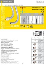
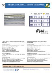
1TUBI METALLICI<br />
A SEMPLICE AGGRAFFATURA<br />
INTERLOCKING METAL FLEXIBLE CONDUITS<br />
SYSTEMSSIMPLE<br />
SISTEMA TUBI FLESSIBILI<br />
FLEXIBLE CONDUIT<br />
art. 667M<br />
MAX<br />
MIN<br />
+250°C<br />
-45°C<br />
CODICE ARTICOLO DIMENSIONI DIMENSIONI PROFILO<br />
Ødmm ØD mm in Pollici m mm<br />
667M1013 10,0 13,0 1/4” 50 30<br />
667M1215 12,0 15,0 3/8” 50 35<br />
667M1518 15,5 18,5 1/2” 50 40<br />
667M2024 20,5 24,5 3/4” 50 50<br />
667M2630 26,5 30,0 1” 25 70<br />
667M3539 35,0 39,5 1”1/4 25 90<br />
667M4044 40,0 44,5 1”1/2 25 105<br />
667M5054 50,5 54,5 2” 25 130<br />
Settori di<br />
Impiego<br />
areas of<br />
application<br />
TERZIARIO BORDO MACCHINA FERROVIARIO<br />
TERTIARY SECTOR INSTALLED ON MACHINES RAILWAY INDUSTRY<br />
CLASSIFICAZIONE CEI EN 61386-1 3356<br />
GRADO DI PROTEZIONE DEL SISTEMA IP 40<br />
<br />
<br />
CLASSIFICAZIONE:<br />
Prodotti in conformità alle norme CEI EN 61386-1 e 61386-23<br />
Codici di classificazione significativi: 3 3 5 6<br />
Resistenza alla compressione: Medio (750N)<br />
Resistenza all’urto: Medio (2J)<br />
Resistenza alla corrosione: Media<br />
Resistenza alla trazione: Medio (500N)<br />
Resistenza al carico sospeso: Pesante (450N)<br />
Grado di protezione del sistema: IP 40<br />
Proprietà elettriche: Continuità elettrica garantita<br />
CARATTERISTICHE DEL PRODOTTO:<br />
Tubi flessibili ricavati da nastro di acciaio zincato a caldo con<br />
metodo Sendzimir (UNI EN 10327) profilato ad elica a semplice<br />
aggraffatura.<br />
Presentano ottima flessibilità e buona resistenza meccanica.<br />
Le matasse sono confezionate in scatole di cartone.<br />
CLASSIFICATION:<br />
Manufactured in compliance with CEI EN 61386-1 and 61386-23<br />
Significant classification codes: 3 3 5 6<br />
Crushing resistance: Medium (750N)<br />
Impact resistance: Medium (2J)<br />
Corrosion resistance: Medium<br />
Tensile strength: Medium (500N)<br />
Suspended load capacity: Heavy (450N)<br />
System protection rating: IP 40<br />
Electrical properties: Electrical continuity guaranteed<br />
CHARACTERISTICS:<br />
Simple interlocking <strong>flexible</strong> <strong>conduit</strong>s made from a helical ribbon of<br />
Sendzimir continuous hot-dip zinc coated strip (UNI EN 10327).<br />
They are extremely <strong>flexible</strong> and have an excellent mechanical resistance.<br />
The coils are packed in cartons.<br />
13<br />
Raccordi Utilizzati<br />
Connectors In Use<br />
Cod. 66BOTT<br />
Pag. 35<br />
Cod. 6014<br />
Pag. 29<br />
Cod. 6014-G<br />
Pag. 30<br />
Cod. 6015<br />
6115 Pag. 31<br />
Cod. 6024<br />
Pag. 32<br />
Cod. 6025<br />
Pag. 32<br />
Cod. 6117<br />
Pag. 42
CLASSIFICAZIONE CEI EN 61386-1 3431<br />
GRADO DI PROTEZIONE DEL SISTEMA IP 67<br />
TUBI METALLICI<br />
1<br />
MAX +70°C<br />
MIN<br />
-15°C<br />
CODICE ARTICOLO DIMENSIONI DIMENSIONI PROFILO<br />
grigio nero Ødmm ØD mm in Pollici m mm<br />
6070-10 6070-10N 10,0 15,0 1/4” 50 50<br />
6070-12 6070-12N 12,0 18,0 3/8” 50 60<br />
6070-16 6070-16N 15,5 21,0 1/2” 50 70<br />
6070-22 6070-22N 20,5 27,0 3/4” 50 90<br />
6070-32 6070-32N 26,5 34,0 1” 25 120<br />
6070-38 6070-38N 35,0 43,0 1”1/4 25 150<br />
6070-40 6070-40N 40,0 48,0 1”1/2 25 200<br />
6070-50 6070-50N 50,5 58,5 2” 25 250<br />
Settori di<br />
Impiego<br />
areas of<br />
application<br />
A SEMPLICE AGGRAFFATURA RICOPERTI IN PVC LISCIO<br />
TERZIARIO INDUSTRIALE CHIMICO FARMACEUTICO PROD.ENERGIA BORDO MACCHINA MARINO<br />
TERTIARY SECTOR INDUSTRIAL CHEMICAL AND PHARMACEUTICAL INDUSTRY ENERGY PRODUCTION INSTALLED ON MACHINES MARITIME INDUSTRY<br />
SIMPLE INTERLOCKING METAL FLEXIBLE CONDUITS COATED IN SMOOTH PVC<br />
art. 6070<br />
SISTEMA TUBI FLESSIBILI<br />
FLEXIBLE CONDUIT SYSTEMS<br />
CLASSIFICAZIONE:<br />
Prodotti in conformità alle norme CEI EN 61386-1 e 61386-23<br />
Codici di classificazione significativi: 3 4 3 1<br />
Resistenza alla compressione: Pesante (1250N) fino a 6070-32<br />
Medio (750N) da 6070-38<br />
Resistenza all’urto: Pesante (6J)<br />
Resistenza alla trazione: Medio (500N) fino a cod. 6070-16<br />
Pesante (1000N) da cod. 6070-22<br />
Resistenza al carico sospeso: Pesante (450N)<br />
Autoestinguenza: Non propagante la fiamma<br />
Grado di protezione del sistema: IP 67 con raccordi indicati nella<br />
tabella<br />
Proprietà elettriche: Continuità elettrica garantita e proprietà<br />
isolante<br />
CARATTERISTICHE DEL PRODOTTO:<br />
Tubi flessibili ricavati da nastro di acciaio zincato a caldo con<br />
metodo Sendzimir (UNI EN 10327) profilato ad elica a semplice<br />
aggraffatura, ricoperti in PVC autoestinguente, liscio esternamente.<br />
Resistenti ai più comuni oli e grassi, presentano ottima flessibilità e<br />
buona resistenza meccanica.<br />
CLASSIFICATION:<br />
Manufactured in compliance with CEI EN 61386-1 and 61386-23<br />
Significant classification codes: 3 4 3 1<br />
Crushing resistance: Heavy (1250N) until cod. 6070-32 Medium<br />
(750N) from cod.6070-38<br />
Impact resistance: Heavy<br />
Tensile strength: Medium (500N) until cod.6070-16 Heavy (1000N)<br />
from. cod.6070-22<br />
Suspended load capacity: Heavy (450N)<br />
Self-extinguishing:flame retardant<br />
System protection rating: IP67 with the fittings shown in the following<br />
schedule<br />
Electrical properties: Electrical continuity guaranteed<br />
CHARACTERISTICS:<br />
Simple interlocking <strong>flexible</strong> <strong>conduit</strong>s made from a helical ribbon of<br />
Sendzimir continuous hot-dip zinc coated strip (UNI EN 10327), selfextinguishing<br />
PVC.<br />
Resistant to most types of oils and greases, they are extremely <strong>flexible</strong><br />
and have excellent levels of mechanical resistance.<br />
14<br />
Colori Disponibili<br />
Colours<br />
GRIGIO SCURO<br />
Ø d<br />
DARK GREY<br />
NERO<br />
BLACK<br />
Raccordi Utilizzati<br />
Connectors In Use<br />
Cod. 6014<br />
Pag. 29<br />
Ø D<br />
Cod. 6014-G<br />
Pag. 30<br />
Cod. 6015<br />
6115 Pag. 31<br />
Cod. 6024<br />
Pag. 32<br />
Cod. 6025<br />
Pag. 32<br />
Cod. 6117<br />
Pag. 42
1TUBI METALLICI<br />
SISTEMA TUBI FLESSIBILI<br />
FLEXIBLE CONDUIT SYSTEMS<br />
A SEMPLICE AGGRAFFATURA RICOPERTI IN EVA LISCIO<br />
SIMPLE INTERLOCKING METAL FLEXIBLE CONDUITS IN SMOOTH EVA<br />
art. 607E<br />
MAX<br />
MIN<br />
+70°C<br />
-25°C<br />
CODICE ARTICOLO DIMENSIONI DIMENSIONI PROFILO<br />
Ødmm ØD mm in Pollici m mm<br />
607E010 10,0 15,0 1/4” 50 60<br />
607E012 12,0 18,0 3/8” 50 70<br />
607E016 15,5 21,0 1/2” 50 90<br />
607E022 20,5 27,0 3/4” 50 120<br />
607E032 26,5 34,0 1” 25 140<br />
607E038 35,0 43,0 1”1/4 25 190<br />
607E040 40,0 48,0 1”1/2 25 240<br />
607E050 50,5 58,5 2” 25 300<br />
Settori di<br />
Impiego<br />
areas of<br />
application<br />
TERZIARIO<br />
TERTIARY SECTOR<br />
FERROVIARIO<br />
RAILWAY INDUSTRY<br />
CLASSIFICAZIONE CEI EN 61386-1 3441<br />
GRADO DI PROTEZIONE DEL SISTEMA IP 67<br />
CLASSIFICAZIONE:<br />
Prodotti in conformità alle norme CEI EN 61386-1, CEI EN 61386-23, UNI<br />
CEI 11170-3:2005.<br />
Codici di classificazione significativi: 3 4 4 1<br />
Resistenza alla compressione: Pesante (1250N) fino 607E032<br />
Medio (750N) da 607E038<br />
Resistenza all’urto: Pesante (6J)<br />
Resistenza alla trazione: Medio(500N) fino 607E016<br />
Pesante (100N) da 607E022<br />
Resistenza al carico sospeso: Pesante (850N)<br />
Autoestinguenza CEI EN 61386: Non propagante la fiamma<br />
Emissione fumi F1 in conformità alla norma NF F 16-101<br />
Proprietà elettriche: Continuità elettrica garantita<br />
Grado di protezione del sistema: IP 67 con i raccordi indicati nella tabella<br />
CERTIFICAZIONI:<br />
Rapporti di prova LAPI Laboratorio Prevenzione Incendi <strong>srl</strong>:<br />
<br />
<br />
<br />
<br />
CARATTERISTICHE DEL PRODOTTO:<br />
Tubi flessibili ricavati da nastro di acciaio zincato Sendzimir (UNI EN 10327),<br />
profilato ad elica a semplice aggraffatura.<br />
Il rivestimento è realizzato in EVA, termoplastico ritardante la fiamma, a bassa<br />
emissione di gas tossici e corrosivi, privo di alogeni,con superficie esterna<br />
liscia ed ancoraggio sulle spire.<br />
Resistenti ai più comuni oli e grassi, presentano buona flessibilità e buona<br />
resistenza meccanica.<br />
CLASSIFICATION:<br />
Manufactured in compliance with CEI EN 61386-1, CEI EN 61396-23, UNI CEI<br />
11170-3:2005 Standards.<br />
Significant classification codes: 3 4 4 1<br />
Pressing resistance: Heavy (1250N) until 607E032 code<br />
Medium (750N) from 607E038<br />
Impact resistance: Heavy (6J)<br />
Traction resistance: Medium (500N) until 607E016 code<br />
Heavy (100N) until 607E022<br />
Overhung load resistance: Heavy (850N)<br />
Self-extinguishing rating in compliance with CEI EN 61386 standard: Flame<br />
Retardant<br />
Fume Emission F1 in compliance with NF F 16-101 standard<br />
Electrical Properties: Electrical continuity guaranteed<br />
System Protection Rating: IP67 with connectors shown in the accompanying<br />
table.<br />
CERTIFICATION REPORTS:<br />
LAPI (Laboratorio Prevenzione Incendi Srl) Test Reports :<br />
<br />
Standard<br />
<br />
<br />
<br />
CHARACTERISTICS:<br />
Flexible <strong>conduit</strong>s made from Sendzimir galvanized steel ribbon (UNI EN 10327<br />
Standard), with helicoidal profile and simple interlocking.<br />
The coating is made of thermoplastic EVA which is a flame retardant material<br />
with a low level of toxic and corrosive gas emission, halogen-free, with a smooth<br />
external surface and thread fastening.<br />
These <strong>conduit</strong>s are resistant to common oils and grease and have good flexibility<br />
and good mechanical resistance.<br />
Colori Disponibili<br />
Colours<br />
15<br />
GRIGIO SCURO<br />
DARK GREY<br />
<br />
Raccordi Utilizzati<br />
Connectors In Use<br />
Cod. 6014<br />
Pag. 29<br />
<br />
Cod. 6014-G<br />
Pag. 30<br />
Cod. 6015<br />
6115 Pag. 31<br />
Cod. 6024<br />
Pag. 32<br />
Cod. 6025<br />
Pag. 32<br />
Cod. 6117<br />
Pag. 42
MAX<br />
MIN<br />
+70°C<br />
-25°C<br />
CODICE ARTICOLO DIMENSIONI DIMENSIONI PROFILO<br />
Ødmm ØD mm in Pollici m mm<br />
607ETX010 10,0 15,0 1/4” 50 60<br />
607ETX012 12,0 18,0 3/8” 50 70<br />
607ETX016 15,5 21,0 1/2” 50 90<br />
607ETX022 20,5 27,0 3/4” 50 120<br />
607ETX032 26,5 34,0 1” 25 140<br />
607ETX038 35,0 43,0 1”1/4 25 190<br />
607ETX040 40,0 48,0 1”1/2 25 240<br />
607ETX050 50,5 58,5 2” 25 300<br />
70<br />
60<br />
50<br />
40<br />
30<br />
20<br />
10<br />
0<br />
50 250 450 650 850<br />
Frequenza MHz<br />
TUBI METALLICI<br />
1<br />
A SEMPLICE AGGRAFFATURA RICOPERTI IN EVA LISCIO E PROTETTI CON TRECCIA INOX<br />
SIMPLE INTERLOCKING METAL FLEXIBLE CONDUITS COATED IN SMOOTH EVA AND PROTECTED BY STAINLEASS STEEL BANDING<br />
CLASSIFICAZIONE CEI EN 61386-1 3441<br />
GRADO DI PROTEZIONE DEL SISTEMA IP 67<br />
Nota: la dimensione ØD si riferisce al tubo metallico rivestito, indicativamente la trecciatura comporta un aumento di 1,5 mm sul Ø esterno.<br />
Note: Diameter dimension refers solely to the coated metal <strong>conduit</strong>; the banding adds an additional 1.5 mm to the external diameter.<br />
CLASSIFICAZIONE:<br />
Prodotti in conformità alle norme CEI EN 61386-1, CEI EN 61386-23, UNI<br />
CEI 11170-3:2005.<br />
Codici di classificazione significativi: 3 4 4 1<br />
Resistenza alla compressione:Pesante (1250N) fino 607ETX032<br />
Medio (750N) da 607ETX038<br />
Resistenza all’urto:Pesante (6J)<br />
Resistenza alla trazione: Medio(500N) fino 607ETX016<br />
Pesante (100N) da 607ETX022<br />
Resistenza al carico sospeso: Pesante (850N)<br />
Autoestinguenza CEI EN 61386: Non propagante la fiamma<br />
Emissione fumi F1 in conformità alla norma NF F 16-101<br />
Proprietà elettriche: Continuità elettrica garantita<br />
Grado di protezione del sistema: IP 67 con i raccordi indicati nella tabella<br />
Schermatura EMC secondo IEC TS 61587: 30-230MHz Livello1 (Abbattimento<br />
minimo 35dB)<br />
CERTIFICAZIONI:<br />
Rapporti di prova LAPI Laboratorio Prevenzione Incendi <strong>srl</strong>:<br />
<br />
<br />
<br />
<br />
CARATTERISTICHE DEL PRODOTTO:<br />
Tubi flessibili ricavati da nastro di acciaio zincato Sendzimir (UNI EN 10327),<br />
profilato ad elica a semplice aggraffatura.<br />
Il rivestimento è realizzato in EVA, termoplastico ritardante la fiamma, a bassa<br />
emissione di gas tossici e corrosivi e privo di alogeni, con superficie esterna<br />
liscia ed ancoraggio sulle spire.<br />
Sono protetti da una treccia metallica in acciaio inox AISI 304, che ne<br />
conferisce una elevata resistenza all’usura, all’abrasione ed allo scintillio.<br />
Resistenti ai più comuni oli e grassi, presentano buona flessibilità e resistenza<br />
meccanica.<br />
Offrono una buona protezione dalle interferenze elettromagnetiche su<br />
un’ampia banda di frequenze.<br />
CLASSIFICATION:<br />
Manufactured in compliance with CEI EN 61386-1, CEI EN 61396-23, UNI CEI<br />
11170-3:2005 Standards.<br />
Significant classification codes: 3 4 4 1<br />
<br />
<br />
Impact resistance: Heavy (6J)<br />
<br />
<br />
Overhung load resistance: Heavy (850N)<br />
Self-extinguishing rating in compliance with CEI EN 61386 standard: Flame<br />
Retardant<br />
Fume Emission F1 in compliance with NF F 16-101 standard<br />
Electrical Properties: Electrical continuity guaranteed<br />
System Protection Rating: IP67 with connectors shownin the accompanying table.<br />
EMC Shielding in compliance with IEC TS 61587 Standard: 30-230MHz Level<br />
1 (Minimum abatement 35dB)<br />
CERTIFICATION REPORTS:<br />
LAPI (Laboratorio Prevenzione Incendi Srl) Test Reports :<br />
<br />
Standard<br />
<br />
<br />
<br />
CHARACTERISTICS:<br />
Flexible <strong>conduit</strong>s made from Sendzimir galvanized steel ribbon (UNI EN 10327<br />
Standard), with helicoidal profile and simple interlocking.<br />
The coating is made of thermoplastic EVA which is a flame retardant material<br />
with a low level of toxic and corrosive gas emission, halogen-free, with a smooth<br />
external surface and thread fastening.<br />
They are protected by an AISI 304 stainless steel metal braid, that renders the<br />
<strong>conduit</strong> highly resistant to wear, abrasion and electric sparks.<br />
These <strong>conduit</strong>s are resistant to common oils and grease and have good flexibility<br />
and good mechanical resistance.<br />
They also offer good protection against electromagnetic interference across a<br />
large wave band.<br />
They are protected by an AISI 304 stainless steel<br />
metal braid, that renders the <strong>conduit</strong> highly resistant<br />
to wear, abrasion and electric sparks.<br />
These <strong>conduit</strong>s are resistant to common oils and<br />
grease and have good flexibility and good<br />
mechanical resistance.<br />
They also offer good protection against<br />
electromagnetic interference across a large wave<br />
band.<br />
dB<br />
16<br />
art. 607ETX<br />
Settori di<br />
Impiego<br />
areas of<br />
application<br />
TERZIARIO<br />
TERTIARY SECTOR<br />
Colore Distintivo Treccia<br />
Braid Colours<br />
<br />
FERROVIARIO<br />
RAILWAY INDUSTRY<br />
NESSUN RIFERIMENTO<br />
NO REFERENCE<br />
SISTEMA TUBI FLESSIBILI<br />
FLEXIBLE CONDUIT SYSTEMS<br />
Raccordi Utilizzati<br />
Connectors In Use<br />
Cod. 6014<br />
Pag. 29<br />
<br />
Cod. 6014-G<br />
Pag. 30<br />
Cod. 6015<br />
6115 Pag. 31<br />
Cod. 6024<br />
Pag. 32<br />
Cod. 6025<br />
Pag. 32<br />
Cod. 6117<br />
Pag. 42
1TUBI METALLICI<br />
SISTEMA TUBI FLESSIBILI<br />
FLEXIBLE CONDUIT SYSTEMS<br />
A SEMPLICE AGGRAFFATURA RICOPERTI IN PVC ASPIRATO<br />
SIMPLE INTERLOCKING METAL FLEXIBLE CONDUITS WITH VACUUM PVC COATING<br />
art. 6071<br />
MAX<br />
MIN<br />
+70°C<br />
-15°C<br />
CODICE ARTICOLO<br />
grigio nero<br />
DIMENSIONI<br />
Ødmm ØD mm<br />
DIMENSIONI<br />
in Pollici<br />
PROFILO<br />
6071-010 6071-010N 10,0 14,0 1/4” 50 30<br />
6071-012 6071-012N 12,0 16,0 3/8” 50 35<br />
6071-015 6071-015N 15,5 19,5 1/2” 50 40<br />
6071-020 6071-020N 20,5 25,5 3/4” 50 60<br />
6071-027 6071-027N 26,5 31,5 1” 25 80<br />
6071-035 6071-035N 35,0 41,0 1”1/4 25 120<br />
6071-040 6071-040N 40,0 46,0 1”1/2 25 150<br />
6071-050 6071-050N 50,5 57,0 2” 25 200<br />
Settori di<br />
Impiego<br />
areas of<br />
application<br />
TERZIARIO<br />
TERTIARY SECTOR<br />
Colori Disponibili<br />
Colours<br />
BORDO MACCHINA<br />
INSTALLED ON MACHINES<br />
GRIGIO METALLIZZATO<br />
METALLIC GREY<br />
CLASSIFICAZIONE CEI EN 61386-1 3431<br />
GRADO DI PROTEZIONE DEL SISTEMA IP 44<br />
m<br />
NERO: A RICHIESTA PER LOTTI MINIMI<br />
BLACK: AVAILABLE ON REQUEST FOR MINIMUM QUANTITIES<br />
mm<br />
CLASSIFICAZIONE:<br />
Prodotti in conformità alle norme CEI EN 61386-1 e 61386-23<br />
Codici di classificazione significativi: 3 4 3 1<br />
Resistenza alla compressione:Pesante (1250N) fino a 6071-027<br />
Medio (750N) da 6071-035<br />
Resistenza all’urto: Pesante (6J)<br />
Resistenza alla trazione: Medio (500N) fino a cod.6071-015<br />
Pesante (1000 N) da cod.6071-020<br />
Resistenza al carico sospeso: Pesante (450N)<br />
Autoestinguenza: Non propagante la fiamma<br />
Grado di protezione del sistema: IP 44 con raccordi indicati nella<br />
tabella<br />
Proprietà elettriche: Continuità elettrica garantita e proprietà<br />
isolante<br />
CARATTERISTICHE DEL PRODOTTO:<br />
Tubi flessibili ricavati da nastro di acciaio zincato a caldo con<br />
metodo Sendzimir (UNI EN 10327) profilato ad elica a semplice<br />
aggraffatura, ricoperti in PVC autoestinguente aspirato.<br />
Resistenti ai più comuni oli e grassi, presentano ottima flessibilità e<br />
buona resistenza meccanica.<br />
CLASSIFICATION:<br />
Manufactured in compliance with CEI EN 61386-1 and 61386-23<br />
Significant classification codes: 3 4 3 1<br />
Crushing resistance: Heavy (1250N) until cod.6071-027 Medium<br />
(750N) from cod. 6071-035<br />
Impact resistance: Heavy (6J)<br />
Tensile strength: Medium (500N) until cod. 6071-015 Heavy (1000N)<br />
from cod. 6071-020<br />
Suspended load capacity: Heavy (450N)<br />
Self-extinguishing in accordance with CEI EN 60529 and CEI EN<br />
50102: Flame retardant.<br />
System Protection Rating: IP44 with connectors shown in the<br />
accompanyng table.<br />
Electrical properties: Electrical continuity guaranteed<br />
CHARACTERISTICS:<br />
Simple interlocking <strong>flexible</strong> <strong>conduit</strong>s made from a helical ribbon of<br />
Sendzimir continuous hot-dip zinc coated strip (UNI EN 10327),<br />
vacuum self-extinguishing PVC.<br />
Resistant to most types of oils and greases, they are extremely <strong>flexible</strong><br />
and have excellent levels of mechanical resistance.<br />
17<br />
Ø d<br />
Raccordi Utilizzati<br />
Connectors In Use<br />
Cod. 6014<br />
Pag. 29<br />
Ø D<br />
Cod. 6014-G<br />
Pag. 30<br />
Cod. 6015<br />
6115 Pag. 31<br />
Cod. 6024<br />
Pag. 32<br />
Cod. 6025<br />
Pag. 32<br />
Cod. 6117<br />
Pag. 42
MAX<br />
MIN<br />
+70°C<br />
-15°C<br />
CODICE ARTICOLO DIMENSIONI DIMENSIONI PROFILO<br />
Ødmm ØD mm in Pollici m mm<br />
6071T-010 10,0 15,0 1/4” 50 30<br />
6071T-012 12,0 18,0 3/8” 50 35<br />
6071T-016 15,5 20,5 1/2” 50 50<br />
6071T-022 20,5 26,5 3/4” 50 65<br />
6071T-032 26,5 33,0 1” 25 80<br />
6071T-038 35,0 42,5 1”1/4 25 120<br />
6071T-040 40,0 47,5 1”1/2 25 150<br />
6071T-050 50,5 58,5 2” 25 220<br />
70<br />
60<br />
50<br />
40<br />
30<br />
20<br />
10<br />
0<br />
50 250 450 650 850<br />
Frequenza MHz<br />
TUBI METALLICI<br />
1<br />
A SEMPLICE AGGRAFFATURA RICOPERTI IN PVC ASPIRATO E PROTETTI CON TRECCIA METALLICA<br />
SIMPLE INTERLOCKING METAL FLEXIBLE CONDUITS COATED IN A VACUUM PVC COATING AND PROTECTED BY GALVANISED STEEL BRAID<br />
CLASSIFICAZIONE CEI EN 61386-1 3431<br />
GRADO DI PROTEZIONE DEL SISTEMA IP 44<br />
Settori di<br />
Impiego<br />
areas of<br />
application<br />
TERZIARIO INDUSTRIALE BORDO MACCHINA FERROVIARIO<br />
TERTIARY SECTOR INDUSTRIAL INSTALLED ON MACHINE RAILWAY INDUSTRY<br />
BLU<br />
Colore Distintivo Treccia<br />
Braid Colours<br />
BLUE<br />
CLASSIFICAZIONE:<br />
Prodotti in conformità alle norme CEI EN 61386-1 e 61386-23<br />
Codici di classificazione significativi: 3 4 3 1<br />
Resistenza alla compressione:Pesante (1250N) fino a 6071T-032<br />
Medio (750N) da 6071T-038<br />
Resistenza all’urto: Pesante (6J)<br />
Resistenza alla trazione: Medio (500N) fino a cod.6071T-016<br />
Pesante (1000 N) da cod.6071T-022<br />
Resistenza al carico sospeso: Pesante (450N)<br />
Autoestinguenza: Non propagante la fiamma<br />
Grado di protezione del sistema: IP 44 con raccordi indicati nella<br />
tabella<br />
Proprietà elettriche: Continuità elettrica garantita<br />
Schermatura EMC secondo IEC TS 61587: 30-230MHz Livello1<br />
(Abbattimento minimo 35dB)<br />
CARATTERISTICHE DEL PRODOTTO:<br />
Tubi flessibili ricavati da nastro di acciaio zincato a caldo con<br />
metodo Sendzimir (UNI EN 10327) profilato ad elica a semplice<br />
aggraffatura, ricoperti in PVC autoestinguente aspirato, protetti<br />
con treccia di acciaio zincato che conferisce un’elevata resistenza<br />
all’usura.<br />
Resistenti ai più comuni oli e grassi, presentano ottima flessibilità e<br />
buona resistenza meccanica.<br />
Offrono una buona protezione dalle interferenze elettromagnetiche<br />
su un’ampia banda di frequenze.<br />
CLASSIFICATION:<br />
Manufactured in compliance with CEI EN 61386-1 and 61386-23<br />
Significant classification codes: 3 4 3 1<br />
Crushing resistance: Heavy (1250N) until cod.6071T-032 Medium<br />
(750N) from cod. 6071T-038<br />
Impact resistance: Heavy (6J)<br />
Tensile strength: Medium (500N) until cod. 6071T-016 Heavy (1000N)<br />
from cod. 6071T-022<br />
Suspended load capacity: Heavy (450N)<br />
Self-extinguishing in accordance: Flame retardant.<br />
System Protection Rating: IP67 with connectors shown in the<br />
accompanyng table.<br />
EMC shielding in compliance with IEC T561587: 30-230 MHZ level<br />
1 (Minimum abatement 35dB)<br />
CHARACTERISTICS:<br />
Simple interlocking <strong>flexible</strong> <strong>conduit</strong>s made from a helical ribbon of<br />
Sendzimir continuous hot-dip zinc coated strip (UNI EN 10327), selfextinguishing<br />
PVC protected by galvanised steel braid that provides<br />
high resistance against wear. Resistant to most types of oils and greases,<br />
they are extremely <strong>flexible</strong> and have excellent levels of mechanical<br />
resistance.<br />
They offer a good protection from electromagnetic interferences in a<br />
large wave band.<br />
18<br />
dB<br />
art. 6071T<br />
Ø d<br />
SISTEMA TUBI FLESSIBILI<br />
FLEXIBLE CONDUIT SYSTEMS<br />
Raccordi Utilizzati<br />
Connectors In Use<br />
Cod. 6014<br />
Pag. 29<br />
Ø D<br />
Cod. 6014-G<br />
Pag. 30<br />
Cod. 6015<br />
6115 Pag. 31<br />
Cod. 6024<br />
Pag. 32<br />
Cod. 6025<br />
Pag. 32<br />
Cod. 6117<br />
Pag. 42
1TUBI METALLICI<br />
SISTEMA TUBI FLESSIBILI<br />
FLEXIBLE CONDUIT SYSTEMS<br />
A SEMPLICE AGGRAFFATURA RICOPERTI IN EVA ASPIRATO<br />
SIMPLE INTERLOCKING METAL FLEXIBLE CONDUITS COATED IN VACUUM EVA<br />
art. 6071E<br />
MAX<br />
MIN<br />
+70°C<br />
-25°C<br />
CODICE ARTICOLO DIMENSIONI DIMENSIONI PROFILO<br />
Ødmm ØD mm in Pollici<br />
m mm<br />
6071E-010 10,0 14,0 1/4” 50 30<br />
6071E-012 12,0 16,0 3/8” 50 35<br />
6071E-015 15,5 19,5 1/2” 50 50<br />
6071E-020 20,5 25,5 3/4” 50 65<br />
6071E-027 26,5 31,5 1” 25 80<br />
6071E-035 35,0 41,0 1”1/4 25 120<br />
6071E-040 40,0 46,0 1”1/2 25 150<br />
6071E-050 50,5 57,0 2” 25 220<br />
Settori di<br />
Impiego<br />
areas of<br />
application<br />
TERZIARIO<br />
TERTIARY SECTOR<br />
FERROVIARIO<br />
RAILWAY INDUSTRY<br />
CLASSIFICAZIONE CEI EN 61386-1 3441<br />
GRADO DI PROTEZIONE DEL SISTEMA IP 44<br />
CLASSIFICAZIONE:<br />
Prodotti in conformità alle norme CEI EN 61386-1, CEI EN 61386-23, UNI<br />
CEI 11170-3:2005.<br />
Codici di classificazione significativi: 3 4 4 1<br />
Resistenza alla compressione:Pesante (1250N) fino 6071E-027<br />
Medio (750N) da 6071E-035<br />
Resistenza all’urto: Pesante (6J)<br />
Resistenza alla trazione: Medio(500N) fino 6071E-015<br />
Pesante (100N) da 6071E-020<br />
Resistenza al carico sospeso: Pesante (850N)<br />
Autoestinguenza CEI EN 61386: Non propagante la fiamma<br />
Emissione fumi F1 in conformità alla norma NF F 16-101<br />
Proprietà elettriche: Continuità elettrica garantita<br />
Grado di protezione del sistema: IP 44 con i raccordi indicati nella tabella.<br />
CERTIFICAZIONI:<br />
Rapporti di prova LAPI Laboratorio Prevenzione Incendi <strong>srl</strong>:<br />
<br />
<br />
<br />
<br />
CARATTERISTICHE DEL PRODOTTO:<br />
Tubi flessibili ricavati da nastro di acciaio zincato Sendzimir (UNI EN 10327),<br />
profilato ad elica a semplice aggraffatura.<br />
Il rivestimento è realizzato in EVA aspirato, termoplastico ritardante la fiamma,<br />
a bassa emissione di gas tossici e corrosivi, privo di alogeni.<br />
Resistenti ai più comuni oli e grassi, presentano ottima flessibilità e buona<br />
resistenza meccanica.<br />
CLASSIFICATION:<br />
Manufactured in compliance with CEI EN 61386-1, CEI EN 61396-23, UNI CEI<br />
11170-3:2005 Standards.<br />
Significant classification codes: 3 4 4 1<br />
Pressing resistance: Heavy (1250N) until 6071E-027 code Medium (750N) from<br />
6071E-035<br />
Impact resistance: Heavy (6J)<br />
Traction resistance: Medium (500N) until 6071E-015 code Heavy (100N) until<br />
6071-E020<br />
Overhung load resistance: Heavy (850N)<br />
Self-extinguishing rating in compliance with CEI EN 61386 standard: Flame<br />
Retardant<br />
Fume Emission F1 in compliance with NF F 16-101 standard<br />
Electrical Properties: Electrical continuity guaranteed<br />
System Protection Rating: IP44 with connectors shown in the accompanying<br />
table.<br />
CERTIFICATION REPORTS:<br />
LAPI (Laboratorio Prevenzione Incendi Srl) Test Reports :<br />
<br />
Standard<br />
<br />
<br />
<br />
CHARACTERISTICS:<br />
Flexible <strong>conduit</strong>s made from Sendzimir galvanized steel ribbon (UNI EN 10327<br />
Standard), with helicoidal profile and simple interlocking.<br />
The coating is made of vacuum thermoplastic EVA which is a flame retardant<br />
material with a low level of toxic and corrosive gas emission, halogen-free.<br />
These <strong>conduit</strong>s are resistant to common oils and grease and have good flexibility<br />
and good<br />
Colori Disponibili<br />
Colours<br />
19<br />
GRIGIO SCURO<br />
DARK GREY<br />
Ø d<br />
Raccordi Utilizzati<br />
Connectors In Use<br />
Cod. 6014<br />
Pag. 29<br />
Ø D<br />
Cod. 6014-G<br />
Pag. 30<br />
Cod. 6015<br />
6115 Pag. 31<br />
Cod. 6024<br />
Pag. 32<br />
Cod. 6025<br />
Pag. 32<br />
Cod. 6117<br />
Pag. 42
CODICE ARTICOLO<br />
treccia treccia<br />
DIMENSIONI<br />
Ødmm ØD mm<br />
DIMENSIONI<br />
in Pollici<br />
PROFILO<br />
MAX<br />
MIN<br />
m<br />
+70°C<br />
-25°C<br />
zincata inox<br />
6071ET-010 6071ETX-010 10,0 14,0 1/4” 50 30<br />
6071ET-012 6071ETX-012 12,0 16,0 3/8” 50 35<br />
6071ET-016 6071ETX-016 15,5 19,5 1/2” 50 50<br />
6071ET-022 6071ETX-022 20,5 25,5 3/4” 50 65<br />
6071ET-032 6071ETX-032 26,5 31,5 1” 25 80<br />
6071ET-038 6071ETX-038 35,0 41,0 1”1/4 25 120<br />
6071ET-040 6071ETX-040 40,0 46,0 1”1/2 25 150<br />
6071ET-050 6071ETX-050 50,5 57,0 2” 25 220<br />
70<br />
60<br />
50<br />
40<br />
30<br />
20<br />
10<br />
0<br />
50 250 450 650 850<br />
Frequenza MHz<br />
dB<br />
mm<br />
TUBI METALLICI<br />
1<br />
A SEMPLICE AGGRAFFATURA RICOPERTI IN EVA ASPIRATO E PROTETTI CON TRECCIA METALLICA<br />
CLASSIFICAZIONE CEI EN 61386-1 3441<br />
GRADO DI PROTEZIONE DEL SISTEMA IP 44<br />
SIMPLE INTERLOCKING METAL FLEXIBLE CONDUITS COATED IN VACUUM EVA AND PROTECTED BY METAL BANDING<br />
Nota: la dimensione ØD si riferisce al tubo metallico rivestito, indicativamente la trecciatura comporta un aumento di 1,5 mm sul Ø esterno.<br />
Note: Diameter dimension refers solely to the coated metal <strong>conduit</strong>; the banding adds an additional 1.5 mm to the external diameter.<br />
CLASSIFICAZIONE:<br />
Prodotti in conformità alle norme CEI EN 61386-1, CEI EN 61386-23, UNI<br />
CEI 11170-3:2005.<br />
Codici di classificazione significativi: 3 4 4 1<br />
Resistenza alla compressione:Pesante (1250N) fino 6071E-027<br />
Medio (750N) da 6071E-035<br />
Resistenza all’urto: Pesante (6J)<br />
Resistenza alla trazione: Medio(500N) fino 6071E-015<br />
Pesante (100N) da 6071E-020<br />
Resistenza al carico sospeso: Pesante (850N)<br />
Autoestinguenza CEI EN 61386: Non propagante la fiamma<br />
Emissione fumi F1 in conformità alla norma NF F 16-101<br />
Proprietà elettriche: Continuità elettrica garantita<br />
Grado di protezione del sistema: IP 44 con i raccordi nella tabella.<br />
Schermatura EMC secondo IEC TS 61587: 30-230MHz Livello1 (Abbattimento<br />
minimo 35dB)<br />
CERTIFICAZIONI:<br />
Rapporti di prova LAPI Laboratorio Prevenzione Incendi <strong>srl</strong>:<br />
<br />
<br />
<br />
<br />
CARATTERISTICHE DEL PRODOTTO:<br />
Tubi flessibili ricavati da nastro di acciaio zincato Sendzimir (UNI EN 10327),<br />
profilato ad elica a semplice aggraffatura.<br />
Il rivestimento è realizzato in EVA aspirato, termoplastico ritardante la fiamma,<br />
a bassa emissione di gas tossici e corrosivi, privo di alogeni.<br />
Sono protetti da una treccia metallica in acciaio zincato (cod.6071ET)<br />
o in acciaio inox AISI 304 (cod.6071ETX), che ne conferisce una elevata<br />
resistenza all’usura, all’abrasione ed allo scintillio.<br />
Resistenti ai più comuni oli e grassi, presentano ottima flessibilità e buona<br />
resistenza meccanica.<br />
Offrono una buona protezione dalle interferenze elettromagnetiche su<br />
un’ampia banda di frequenze.<br />
CLASSIFICATION:<br />
Manufactured in compliance with CEI EN 61386-1, CEI EN 61396-23, UNI CEI<br />
11170-3:2005 Standards.<br />
Significant classification codes: 3 4 4 1<br />
Pressing resistance: Heavy (1250N) until 607E-027 code<br />
Medium (750N) from 607E-035<br />
Impact resistance: Heavy (6J)<br />
Traction resistance: Medium (500N) until 607E-015 code<br />
Heavy (100N) until 607E-020<br />
Overhung load resistance: Heavy (850N)<br />
Self-extinguishing rating in compliance with CEI EN 61386 standard: Flame<br />
Retardant<br />
Fume Emission F1 in compliance with NF F 16-101 standard<br />
Electrical Properties: Electrical continuity guaranteed<br />
System Protection Rating: IP44 with connectors shown in the accompanying table.<br />
EMC Shielding in compliance with IEC TS 61587 Standard: 30-230MHz Level<br />
1 (Minimum abatement 35dB)<br />
CERTIFICATION REPORTS:<br />
LAPI (Laboratorio Prevenzione Incendi Srl) Test Reports :<br />
<br />
Standard<br />
<br />
<br />
<br />
CHARACTERISTICS:<br />
Flexible <strong>conduit</strong>s made from Sendzimir galvanized steel ribbon (UNI EN 10327<br />
Standard), with helicoidal profile and simple interlocking.<br />
The coating is made of vacuum thermoplastic EVA which is a flame retardant<br />
material with a low level of toxic and corrosive gas emission and halogen-free.<br />
They are protected by a galvanised steel braid (cod. 6071ET) or AISI 304<br />
<br />
abrasion and electric sparks.<br />
These <strong>conduit</strong>s are resistant to common oils and grease and have good flexibility<br />
and good mechanical resistance.<br />
They also offer good protection against electromagnetic interference across a<br />
large wave band.<br />
20<br />
art. 6071ETX - 6071ET<br />
Settori di<br />
Impiego<br />
areas of<br />
application<br />
TERZIARIO<br />
TERTIARY SECTOR<br />
Colore Distintivo Treccia<br />
Braid Colours<br />
Ø d<br />
FERROVIARIO<br />
RAILWAY INDUSTRY<br />
ZINCATA: VERDE<br />
GALVANISED: GREEN<br />
SISTEMA TUBI FLESSIBILI<br />
FLEXIBLE CONDUIT SYSTEMS<br />
INOX: NESSUN RIFERIMENTO<br />
STAINLESS STEEL: NO REFERENCE<br />
Raccordi Utilizzati<br />
Connectors In Use<br />
Cod. 6014<br />
Pag. 29<br />
Ø D<br />
Cod. 6014-G<br />
Pag. 30<br />
Cod. 6015<br />
6115 Pag. 31<br />
Cod. 6024<br />
Pag. 32<br />
Cod. 6025<br />
Pag. 32<br />
Cod. 6117<br />
Pag. 42
1TUBI METALLICI<br />
SISTEMA TUBI FLESSIBILI<br />
FLEXIBLE CONDUIT SYSTEMS<br />
A DOPPIA AGGRAFFATURA<br />
DOUBLE INTERLOCKING METAL FLEXIBLE CONDUITS<br />
art. 667DM<br />
MAX<br />
MIN<br />
+250°C<br />
-45°C<br />
CODICE ARTICOLO<br />
Settori di<br />
Impiego<br />
areas of<br />
application<br />
DIMENSIONI<br />
Ødmm ØD mm<br />
DIMENSIONI<br />
in Pollici<br />
PROFILO<br />
667DM10 10,0 13,0 1/4” 50 50<br />
667DM12 12,0 15,0 3/8” 50 55<br />
667DM15 15,5 18,5 1/2” 50 60<br />
TERZIARIO BORDO MACCHINA FERROVIARIO<br />
TERTIARY SECTOR INSTALLED ON MACHINES RAILWAY INDUSTRY<br />
CLASSIFICAZIONE CEI EN 61386-1 4456<br />
GRADO DI PROTEZIONE DEL SISTEMA IP 40<br />
m<br />
mm<br />
<br />
<br />
CLASSIFICAZIONE:<br />
Prodotti in conformità alle norme CEI EN 61386-1 e 61386-23<br />
Codici di classificazione significativi: 4 4 5 6<br />
Resistenza alla compressione: Pesante (1250N)<br />
Resistenza all’urto: Pesante (6J)<br />
Resistenza alla corrosione: Media<br />
Resistenza alla trazione:Pesante (1000N)<br />
Resistenza al carico sospeso: Pesante (450N)<br />
Grado di protezione del sistema: IP 40<br />
Proprietà elettriche: Continuità elettrica garantita<br />
CARATTERISTICHE DEL PRODOTTO:<br />
Tubi flessibili ricavati da nastro di acciaio zincato a caldo con<br />
metodo Sendzimir (UNI EN 10327) profilato ad elica a doppia<br />
aggraffatura.<br />
Presentano buona flessibilità ed ottima resistenza meccanica, in<br />
modo particolare per le sollecitazioni a trazione, torsione ed urto.<br />
Le matasse sono confezionate in scatole di cartone.<br />
CLASSIFICATION:<br />
Manufactured in compliance with CEI EN 61386-1 and 61386-23<br />
Significant classification codes: 4 4 5 6<br />
Crushing resistance: Heavy (1250N)<br />
Impact resistance: Heavy (6J)<br />
Corrosion resistance: Medium<br />
Tensile strength: Heavy (1000N)<br />
Suspended load capacity: Heavy (450N)<br />
System protection rating: IP 40<br />
Electrical properties: Electrical continuity guaranteed<br />
CHARACTERISTICS:<br />
<br />
of Sendzimir continuous hot-dip zinc coated strip (UNI EN 10327<br />
standard).<br />
They are extremely <strong>flexible</strong> and have an excellent mechanical resistance<br />
particulary when subjected to stress resulting from traction, torsion and<br />
impact.<br />
The coils are packed in cartons.<br />
21<br />
Raccordi Utilizzati<br />
Connectors In Use<br />
Cod. 66BOTT<br />
Pag. 35<br />
Cod. 6014<br />
Pag. 29<br />
Cod. 6014-G<br />
Pag. 30<br />
Cod. 6015<br />
6115 Pag. 31<br />
Cod. 6024<br />
Pag. 32<br />
Cod. 6025<br />
Pag. 32<br />
Cod. 6117<br />
Pag. 42
CLASSIFICAZIONE CEI EN 61386-1 4431<br />
GRADO DI PROTEZIONE DEL SISTEMA IP 67<br />
TUBI METALLICI<br />
1<br />
MAX +70°C<br />
MIN<br />
-15°C<br />
CODICE ARTICOLO DIMENSIONI DIMENSIONI PROFILO<br />
grigio nero Ødmm ØD mm in Pollici m mm<br />
607D-10 607D-10N 10,0 15,0 1/4” 50 60<br />
607D-12 607D-12N 12,0 18,0 3/8” 50 70<br />
607D-16 607D-16N 15,5 21,0 1/2” 50 90<br />
607D-22 607D-22N 20,5 27,0 3/4” 50 120<br />
607D-32 607D-32N 26,5 34,0 1” 25 140<br />
607D-38 607D-38N 35,0 43,0 1”1/4 25 190<br />
607D-40 607D-40N 40,0 48,0 1”1/2 25 240<br />
607D-50 607D-50N 50,5 58,5 2” 25 300<br />
607D-63 607D-63N 63,0 74,0 2” 1/2 12 450<br />
607D-75 607D-75N 75,0 84,0 3” 8 500<br />
607D-100 607D-100N 100,0 109,0 4” 8 750<br />
Settori di<br />
Impiego<br />
areas of<br />
application<br />
Colori Disponibili<br />
Colours<br />
INDUSTRIALE PROD.ENERGIA MARINO<br />
INDUSTRIAL ENERGY PRODUCTION MARITIME INDUSTRY<br />
GRIGIO METALLIZZATO<br />
METALLIC GREY<br />
A DOPPIA AGGRAFFATURA RICOPERTI IN PVC LISCIO<br />
NERO: A RICHIESTA PER LOTTI MINIMI<br />
BLACK: AVAILABLE ON REQUEST FOR MINIMUM QUANTITIES<br />
DUOBLE INTERLOCKING METAL FLEXIBLE CONDUITS COATED IN SMOOTH PVC<br />
art. 607D<br />
SISTEMA TUBI FLESSIBILI<br />
FLEXIBLE CONDUIT SYSTEMS<br />
CLASSIFICAZIONE:<br />
Prodotti in conformità alle norme CEI EN 61386-1 e 61386-23<br />
Codici di classificazione significativi: 4 4 3 1<br />
Resistenza alla compressione: Pesante (1250N)<br />
Resistenza all’urto: Pesante (6J)<br />
Resistenza alla trazione: Pesante (1000N)<br />
Resistenza al carico sospeso: Pesante (450N)<br />
Autoestinguenza: Non propagante la fiamma<br />
Grado di protezione del sistema: IP 67 con raccordi indicati in<br />
tabella<br />
Proprietà elettriche: Continuità elettrica garantita e proprietà<br />
isolante<br />
CARATTERISTICHE DEL PRODOTTO:<br />
Tubi flessibili ricavati da nastro di acciaio zincato a caldo con<br />
metodo Sendzimir (UNI EN 10327) profilato ad elica a doppia<br />
aggraffatura, ricoperti in PVC autoestinguente, liscio esternamente e<br />
con ancoraggio sulle spire.<br />
Resistenti ai più comuni oli e grassi, presentano una buona<br />
flessibilità ed ottima resistenza meccanica in modo particolare per<br />
le sollecitazioni a trazione.<br />
CLASSIFICATION:<br />
Manufactured in compliance with CEI EN 61386-1 and 61386-23<br />
Significant classification codes: 4 4 3 1<br />
Resistance to compression: Heavy (1250N)<br />
Resistance to impact: Heavy (6J)<br />
Tensile strength: Heavy (1000N)<br />
Suspended load capacity: Heavy (450N)<br />
Self-extinguishing: Flame retardant<br />
System protection rating: IP 67 with the fittings shown in the<br />
accompanying table.<br />
Electrical Properties: Electrical Continuity guaranteed and insulating<br />
properties<br />
CHARACTERISTICS:<br />
<br />
of Sendzimir continuous hot-dip zinc coated strip (UNI EN 10327<br />
standard), and externally coated in smooth and self-extinguishing PVC.<br />
Resistant to most types of oils and greases, they present a good flexibility<br />
and a really good mechanical resistance when subjected to traction<br />
stresses.<br />
22<br />
<br />
Raccordi Utilizzati<br />
Connectors In Use<br />
Cod. 6014<br />
Pag. 29<br />
Cod. 6014-G<br />
Pag. 30<br />
<br />
Cod. 6015<br />
6115 Pag. 31<br />
Cod. 6024<br />
Pag. 32<br />
Cod. 6025<br />
Pag. 32<br />
Cod. 6117<br />
Pag. 42
1TUBI METALLICI<br />
SISTEMA TUBI FLESSIBILI<br />
FLEXIBLE CONDUIT SYSTEMS<br />
TUBI PIEGHEVOLI IN ACCIAIO INOX<br />
BENDABLE STAINLESS STEEL CONDUITS<br />
art. 607X<br />
MAX<br />
MIN<br />
+110°C<br />
(punte a 140°C)<br />
-45°C<br />
CODICE ARTICOLO DIMENSIONI<br />
Ødmm ØD mm m mm<br />
607X-12 12,8 17,7 15 25<br />
607X-16 16,7 22,2 15 30<br />
607X-22 20,7 27,1 15 35<br />
607X-32 25,6 33,2 15 40<br />
607X-38 32,6 42,0 15 50<br />
Settori di<br />
Impiego<br />
areas of<br />
application<br />
CLASSIFICAZIONE CEI EN 61386-1 5554<br />
GRADO DI PROTEZIONE DEL SISTEMA IP 67<br />
TERZIARIO CHIMICO FARMACEUTICO INFRASTRUTTURE FERROVIARIO<br />
TERTIARY SECTOR CHEMICAL AND PHARMACEUTICAL INDUSTRY INFRASTRUCTURE RAILWAY INDUSTRY<br />
CODICE ARTICOLO<br />
TUBO<br />
PIEGHEVOLE<br />
Ød mm Pz<br />
6060X-12 12,8 20<br />
6060X-16 16,7 20<br />
6060X-22 20,7 20<br />
6060X-32 25,6 20<br />
6060X-38 32,6 20<br />
art. 6060X<br />
KIT PER TUBI PIEGHEVOLI IN ACCIAIO INOX<br />
KIT FOR BENDABLE STAINLESS STEEL CONDUITS<br />
CLASSIFICAZIONE:<br />
Prodotti in conformità alle norme CEI EN 61386-1 e 61386-22<br />
Codici di classificazione significativi: 5 5 5 4<br />
Resistenza alla compressione:Molto Pesante (4000N)<br />
Resistenza all’urto: Molto Pesante (20J)<br />
Resistenza alla trazione: Molto Pesante (2500N)<br />
Resistenza al carico sospeso: Pesante (450N)<br />
Grado di protezione del sistema: IP 67 con raccordi indicati in<br />
tabella ed utilizzando il kit cod. 6060X<br />
Proprietà elettriche: Continuità elettrica garantita<br />
CARATTERISTICHE DEL PRODOTTO:<br />
Tubi pieghevoli ondulati, prodotti in acciaio inox AISI 321 (X6CrNiTi<br />
1811 1.4541 UNI EN 10088-1), particolarmente indicati in<br />
ambienti chimici aggressivi, dotati di buona flessibilità,possono<br />
essere utilizzati anche in particolari condizioni di difficile curvabilità<br />
dei tubi metallici rigidi.<br />
Presentano un’elevata resistenza allo schiacciamento.<br />
Superfici interne ed esterne entrambe ondulate, offrono un ottimo<br />
scorrimento dei cavi durante l’infilaggio.<br />
CLASSIFICATION:<br />
Manufactured in compliance with CEI EN 61386-1 and 61386-22<br />
Significant classification codes: 5 5 5 4<br />
Crushing resistance: Very Heavy (4000 N)<br />
Impact resistance: Very Heavy (20J)<br />
Tensile strength: Very Heavy (2500N)<br />
Suspended load capacity: Heavy (450N)<br />
System protection rating: IP 67 with the fittings shown in the<br />
<br />
Electrical properties: Electrical continuity guaranteed<br />
CHARACTERISTICS:<br />
<br />
corrugated bendable <strong>conduit</strong>s, designed particularly for use in harsh<br />
chemical environments. These <strong>conduit</strong>s can also be used in conditions<br />
where the bendability of rigid metal piping proves difficulty.<br />
High levels of resistance to crushing.<br />
Both the internal and external surfaces are corrugated and this allows a<br />
cable to slide through extremely easily during feeding.<br />
Il kit è costituito da due semigusci<br />
cilindrici in ottone nichelato,<br />
opportunamente sagomati al fine di<br />
inserirsi nell’ondulazione del tubo ed<br />
impedirne lo scorrimento assiale e da<br />
una guarnizione piana che ne assicura<br />
la tenuta stagna. Il kit può essere<br />
montato su qualsiasi raccordo per tubi<br />
metallici flessibili, in sostituzione della<br />
boccola e della virola normalmente in<br />
dotazione.<br />
A kit consisting of two nickel plated<br />
brass half cylinders appropriately<br />
shaped so that they can be inserted<br />
into the corrugation of the <strong>conduit</strong> that<br />
prevents it from sliding, and a flat seal<br />
that guarantees its water tightness.<br />
The kit can be fitted onto any type of<br />
connector for metal <strong>flexible</strong> <strong>conduit</strong>s,<br />
to replace the bushing and the base<br />
normally supplied as standard.<br />
23<br />
Ø d<br />
Raccordi Utilizzati<br />
Connectors In Use<br />
Cod. 6060X<br />
Pag. 23<br />
Cod. 6014<br />
Pag. 29<br />
Ø D<br />
Cod. 6014-G<br />
Pag. 30<br />
Cod. 6015<br />
6115 Pag. 31<br />
Cod. 6024<br />
Pag. 32<br />
Cod. 6025<br />
Pag. 32<br />
Cod. 6117<br />
Pag. 42
CLASSIFICAZIONE CEI EN 61386-1 0231<br />
GRADO DI PROTEZIONE DEL SISTEMA IP 65 - IP 67<br />
CODICE ARTICOLO<br />
GRIGIO<br />
Settori di<br />
Impiego<br />
areas of<br />
application<br />
CODICE ARTICOLO<br />
AZZURRO<br />
CODICE ARTICOLO<br />
NERO<br />
TUBI IN PVC<br />
1<br />
TUBI IN PVC LISCIO<br />
SMOOTH PVC FLEXIBLE CONDUITS<br />
MAX +70°C<br />
MIN<br />
DIMENSIONI<br />
Ødmm ØDmm<br />
-15°C<br />
6085-10 6085-10A 6085-10N 10 14 50<br />
6085-12 6085-12A 6085-12N 12 16 50<br />
6085-15 6085-15A 6085-15N 15 20 50<br />
6085-20 6085-20A 6085-20N 20 26 50<br />
6085-27 6085-27A 6085-27N 27 34 25<br />
6085-36 6085-36A 6085-36N 36 43 25<br />
6085-40 6085-40A 6085-40N 40 48 25<br />
6085-47 6085-47A 6085-47N 47 55 25<br />
BORDO MACCHINA<br />
INSTALLED ON MACHINES<br />
m<br />
art. 6085<br />
SISTEMA TUBI FLESSIBILI<br />
FLEXIBLE CONDUIT SYSTEMS<br />
Colori Disponibili<br />
Colours<br />
GRIGIO METALLIZZATO AZZURRO NERO: A RICHIESTA PER LOTTI MINIMI<br />
METALLIC GREY SKY BLUE BLACK: AVAILABLE ON REQUEST FOR MINIMUM QUANTITIES<br />
Ø d<br />
Ø D<br />
Raccordi Utilizzati<br />
Connectors In Use<br />
CLASSIFICAZIONE:<br />
Prodotti in conformità alle norme CEI EN 61386-1 e 61386-23<br />
Codici di classificazione significativi: 0 2 3 1<br />
Resistenza all’urto: Leggero (1J)<br />
Autoestinguenza: Non propagante la fiamma<br />
Grado di protezione del sistema: IP 65 - IP 67 con raccordi indicati<br />
nella tabella<br />
CARATTERISTICHE DEL PRODOTTO:<br />
Tubi flessibili prodotti in PVC, offrono ottima resistenza ai più<br />
comuni oli, grassi ed acidi diluiti, presentano buona resistenza<br />
all’invecchiamento.<br />
Superfici interne ed esterne lisce.<br />
CLASSIFICATION:<br />
Manufactured in compliance with CEI EN 61386-1 and 61386-23<br />
Significant classification codes: 0 2 3 1<br />
Impact resistance: Light (1J)<br />
Self-extinguishing: Flame retardant.<br />
System protection rating: IP 65 - IP 67 with the fittings shown in the<br />
accompanying table.<br />
CHARACTERISTICS:<br />
PVC <strong>flexible</strong> <strong>conduit</strong>s, resistant to most oils, greases and diluted acids<br />
and in particular to ageing. Both internal and external surfaces are<br />
smooth.<br />
24<br />
Cod. 6057<br />
Pag. 33<br />
IP 67<br />
Cod. 6188<br />
Pag. 34<br />
IP 65<br />
Accessori Utilizzati<br />
Accessories In Use<br />
Cod. 6059<br />
Pag. 35
1TUBI IN PVC<br />
SISTEMA TUBI FLESSIBILI<br />
FLEXIBLE CONDUIT SYSTEMS<br />
TUBI IN PVC LISCIO PROTETTI CON TRECCIA METALLICA<br />
SMOOTH PVC FLEXIBLE CONDUITS PROTECTED BY A METAL BRAIDING<br />
art. 6089<br />
MAX + 70°C<br />
MIN<br />
-15°C<br />
CODICE ARTICOLO<br />
DIMENSIONI<br />
Ødmm ØD mm<br />
m<br />
mm<br />
6089-10 10 15 50 25<br />
6089-12 12 17 50 30<br />
6089-15 15 21 50 40<br />
6089-20 20 27 50 50<br />
6089-28 27 35 25 70<br />
6089-35 36 45 25 110<br />
6089-40 40 50 25 130<br />
6089-47 47 57 25 150<br />
Settori di<br />
Impiego<br />
areas of<br />
application<br />
TERZIARIO<br />
TERTIARY SECTOR<br />
BORDO MACCHINA<br />
INSTALLED ON MACHINES<br />
CLASSIFICAZIONE CEI EN 61386-1 0231<br />
GRADO DI PROTEZIONE DEL SISTEMA IP 67<br />
Colore Distintivo Treccia<br />
Braid Colours<br />
GIALLO/VERDE<br />
YELLOW/GREEN<br />
Ø d<br />
Ø D<br />
CLASSIFICAZIONE:<br />
Prodotti in conformità alle norme CEI EN 61386-1 e 61386-23<br />
Codici di classificazione significativi: 0 2 3 1<br />
Resistenza all’urto: Leggero (1J)<br />
Autoestinguenza: Non propagante la fiamma<br />
Grado di protezione del sistema: IP 67 con raccordi indicati in<br />
tabella<br />
CARATTERISTICHE DEL PRODOTTO:<br />
Tubi flessibili prodotti in PVC, offrono un’ottima resistenza ai più<br />
comuni oli, grassi ed acidi diluiti, presentano buona resistenza<br />
all’invecchiamento.<br />
Sono protetti con trecciatura in fili di acciaio che ne conferiscono<br />
una elevata resistenza all’usura.<br />
Trecciatura standard: filo di acciaio zincato<br />
CLASSIFICATION:<br />
Manufactured in compliance with CEI EN 61386-1 and 61386-23<br />
Significant classification codes: 0 2 3 1<br />
Impact resistance: Light (1J)<br />
Self-extinguishing: Flame retardant<br />
System protection rating: IP 67 with fittings shown in the accompanying<br />
table.<br />
CHARACTERISTICS:<br />
PVC <strong>flexible</strong> <strong>conduit</strong>s having an excellent resistance to most oils, greases<br />
and diluted acids and in particular to ageing.<br />
Protected with a braid of steel wire that offers high levels of protection<br />
against wear and tear.<br />
Standard braiding: galvanised steel wire<br />
25<br />
Raccordi Utilizzati<br />
Connectors In Use<br />
Cod. 6057<br />
Pag. 33<br />
Accessori Utilizzati<br />
Accesories In Use<br />
Cod. 6059<br />
Pag. 35<br />
Cod. 6059T<br />
Pag. 35<br />
Cod. 6058<br />
Pag. 33
CLASSIFICAZIONE CEI EN 61386-1 1311<br />
GRADO DI PROTEZIONE DEL SISTEMA IP 65<br />
CODICE ARTICOLO<br />
grigio nero<br />
MAX<br />
MIN<br />
+70°C<br />
+5°C<br />
(PER IMPIEGHI STATICI)<br />
(STATING WORKING)<br />
DIMENSIONI<br />
Ødmm ØD mm m mm<br />
6080-10B 6080-10N 10,0 14,7 30 30<br />
6080-12B 6080-12N 12,0 16,4 30 35<br />
6080-16B 6080-16N 16,0 20,7 30 45<br />
6080-20B 6080-20N 20,0 24,7 30 60<br />
6080-25B 6080-25N 25,0 30,6 30 70<br />
6080-32B 6080-32N 32,0 38,0 30 90<br />
6080-40B 6080-40N 40,0 46,4 30 110<br />
6080-50B 6080-50N 50,0 57,2 30 135<br />
6080-60B 6080-60N 60,0 68,0 30 200<br />
Settori di<br />
Impiego<br />
areas of<br />
application<br />
TERZIARIO<br />
TERTIARY SECTOR<br />
BORDO MACCHINA<br />
INSTALLED ON MACHINES<br />
art. 6080<br />
TUBI IN PVC<br />
TUBI IN PVC SPIRALATO<br />
HELICAL PVC FLEXIBLE CONDUITS<br />
1<br />
SISTEMA TUBI FLESSIBILI<br />
FLEXIBLE CONDUIT SYSTEMS<br />
Colori Disponibili<br />
Colours<br />
GRIGIO RAL 7035 NERO: A RICHIESTA PER LOTTI MINIMI<br />
RAL 7035 GREY BLACK: AVAILABLE ON REQUEST FOR MINIMUM QUANTITIES<br />
Ø d<br />
Ø D<br />
CLASSIFICAZIONE:<br />
Prodotti in conformità alle norme CEI EN 61386-1 e 61386-23<br />
Codici di classificazione significativi: 1 3 1 1<br />
Resistenza alla compressione: Molto leggero (120N)<br />
Resistenza all’urto:Medio (2J)<br />
Autoestinguenza: Non propagante la fiamma<br />
Grado di protezione del sistema: IP 65 con raccordi indicati in<br />
tabella<br />
CARATTERISTICHE DEL PRODOTTO:<br />
Tubi flessibili prodotti in PVC plastificato, rinforzato con spirale in<br />
PVC rigido antiurto.<br />
Resistenti ai più comuni oli, grassi ed acidi diluiti, presentano buona<br />
resistenza all’invecchiamento.<br />
Superfici interne lisce ed esterne ondulate.<br />
Raccordi Utilizzati<br />
Connectors In Use<br />
Cod. 6188<br />
Pag. 34<br />
CLASSIFICATION:<br />
Manufactured in compliance with CEI EN 61386-1 and 61386-23<br />
Significant classification codes: 1 3 1 1<br />
Crushing resistance: Very light (120N)<br />
Impact resistance: Medium (2J)<br />
Self-extinguishing: Flame retardant.<br />
System protection rating: IP 65 with the fittings shown in the<br />
accompanying table.<br />
CHARACTERISTICS:<br />
PVC plasticized <strong>flexible</strong> <strong>conduit</strong>s, reinforced with rigid, impact-resistant<br />
helical PVC.<br />
Resistant to most oils, greases and diluted acids and in particular<br />
to ageing. Internal surfaces are smooth and external surfaces are<br />
corrugated.<br />
26
1TUBI IN PVC<br />
SISTEMA TUBI FLESSIBILI<br />
FLEXIBLE CONDUIT SYSTEMS<br />
TUBI IN PVC SPIRALATO PESANTE<br />
HEAVY HELICAL PVC FLEXIBLE CONDUITS<br />
art. 6079<br />
MAX<br />
MIN<br />
CODICE ARTICOLO<br />
DIMENSIONI<br />
Ødmm ØD mm<br />
m<br />
mm<br />
6079-10B 10,0 14,0 30 40<br />
6079-12B 12,0 16,4 30 55<br />
6079-16B 16,0 20,7 30 70<br />
6079-20B 20,0 24,7 30 80<br />
6079-28B 28,0 33,5 30 90<br />
6079-35B 35,0 41,0 30 120<br />
6079-40B 40,0 46,4 30 140<br />
6079-50B 50,0 57,2 30 160<br />
Settori di<br />
Impiego<br />
areas of<br />
application<br />
+70°C<br />
+5°C<br />
TERZIARIO<br />
TERTIARY SECTOR<br />
BORDO MACCHINA<br />
INSTALLED ON MACHINES<br />
CLASSIFICAZIONE CEI EN 61386-1 2311<br />
GRADO DI PROTEZIONE DEL SISTEMA IP 65<br />
Colori Disponibili<br />
Colours<br />
GRIGIO METALLIZZATO RAL 7001<br />
METALLIC GREY RAL 7001<br />
Ø d<br />
Ø D<br />
CLASSIFICAZIONE:<br />
Prodotti in conformità alle norme CEI EN 61386-1 e 61386-23<br />
Codici di classificazione significativi: 2 3 1 1<br />
Resistenza alla compressione:Leggero (320N)<br />
Resistenza all’urto: Medio (2J)<br />
Autoestinguenza: Non propagante la fiamma<br />
Grado di protezione del sistema: IP 65 con raccordi indicati in<br />
tabella<br />
CARATTERISTICHE DEL PRODOTTO:<br />
Tubi flessibili prodotti in PVC plastificato ad alto spessore, rinforzato<br />
con spirale in PVC rigido antiurto.<br />
Resistenti ai più comuni oli, grassi ed acidi diluiti, presentano buona<br />
resistenza meccanica ed all’invecchiamento.<br />
Superfici interne ed esterne lisce.<br />
Raccordi Utilizzati<br />
Connectors In Use<br />
Cod. 6188<br />
Pag. 34<br />
CLASSIFICATION:<br />
Manufactured in compliance with CEI EN 61386-1 e 61386-23<br />
Significant classification codes: 2 3 1 1<br />
Crushing resistance: Light (320N)<br />
Impact resistance: Medium (2J)<br />
Self-extinguishing: Flame retardant.<br />
System protection rating: IP 65 with fittings shown in the accompanying<br />
table.<br />
CHARACTERISTICS:<br />
Extra thick, plasticized PVC <strong>flexible</strong> <strong>conduit</strong>s, reinforced with rigid,<br />
impact-resistant helical PVC. Resistant to most oils, greases and diluted<br />
acids and in particular to ageing.<br />
Both internal and external surfaces are smooth<br />
27
MAX<br />
MIN<br />
Tubi Utilizzati<br />
Conduits In Use<br />
+80°C<br />
-20°C<br />
Cod. 667M Pag. 13<br />
Cod. 667DM Pag. 21<br />
+ 66BOTT Pag. 35<br />
Cod. 6070 Pag. 14<br />
Cod. 607E Pag. 15<br />
Cod. 607D Pag. 22<br />
Cod. 607ETX Pag. 16<br />
Cod. 6071 Pag. 17<br />
Cod. 6071E Pag. 19<br />
IP Sistema<br />
IP System<br />
40<br />
67<br />
67<br />
44<br />
RACCORDI<br />
RACCORDI PER TUBI METALLICI FLESSIBILI<br />
CONNECTORS FOR METAL FLEXIBLE CONDUITS<br />
art. 6014 - 6014G - 6015 - 6115 - 6117<br />
F<br />
A C B D<br />
E<br />
1<br />
SISTEMA TUBI FLESSIBILI<br />
FLEXIBLE CONDUIT SYSTEMS<br />
Cod. 6071ETX Pag. 20<br />
Cod. 6071ET Pag. 20<br />
Cod. 607X Pag. 23<br />
+ 6060X Pag. 23<br />
44<br />
67<br />
A: CORPO RACCORDO IN OTTONE NICHELATO<br />
B: DADO DI SERRAGGIO IN OTTONE NICHELATO<br />
C: VIROLA DI CONTATTO METALLICO IN ZAMA ZINCATA<br />
D: BOCCOLA DI BLOCCAGGIO IN NYLON<br />
E: TUBO FLESSIBILE<br />
F: FILETTATURA<br />
A: NICKEL PLATED BRASS CONNECTOR BODY<br />
B: NICKEL PLATED BRASS TIGHTENING NUT<br />
C: GALVANISED ‘ZAMAK’ METALLIC CONTACT BASE<br />
D: NYLON LOCKING BUSHING<br />
E: FLEXIBLE CONDUITS<br />
F: THREAD<br />
CLASSIFICAZIONE:<br />
Prodotti in conformità alle norme CEI EN 61386<br />
Resistenza alla trazione: Pesante (1000N)<br />
Resistenza al carico sospeso: Pesante (450N)<br />
Grado di protezione del sistema: indicato in tabella<br />
Nota: IP 65 per raccordi con filetto maggiore di 2”<br />
Proprietà elettriche: Continuità elettrica garantita<br />
CARATTERISTICHE DEL PRODOTTO:<br />
Sono prodotti in ottone, nichelati successivamente per conferire una<br />
migliore resistenza alle avverse condizioni ambientali in cui verranno<br />
utilizzati.<br />
Il collegamento raccordo-tubo flessibile avviene mediante una virola<br />
che si avvita all’interno del tubo garantendo una elevata resistenza<br />
alla trazione e la continuità elettrica prevista dalle norme CEI. Una<br />
boccola in nylon di forma troncoconica assicura il bloccaggio esterno<br />
del tubo flessibile garantendo una tenuta stagna IP67 (Relazione IMQ<br />
n°1381).<br />
Per assecondare le esigenze di installazione vengono prodotti nelle<br />
versioni: maschio fisso, maschio girevole e femmina fissa.<br />
Le filettature proposte sono: Metrico ISO in conformità con le norme<br />
CEI EN 60423 (IEC60423), GAS cilindrico UNI ISO 228, GAS conico<br />
ISO 7/1 (ex UNI339), PG secondo DIN 40430, e con filettatura NP<br />
ANSI B2.1.<br />
La particolare cura nell’esecuzione di questi raccordi assicura un perfetto<br />
infilaggio dei cavi senza rischio di danneggiamento del rivestimento.<br />
28<br />
CLASSIFICATION:<br />
Manufactured in compliance with CEI EN 61386-<br />
Tensile strength: Heavy (1000N)<br />
Suspended load capacity: Heavy (450N)<br />
System protection ratings: shown in the accompanying table<br />
Note: IP 65 for connectors with threads bigger than 2”<br />
Electrical properties: Electrical continuity guaranteed<br />
CHARACTERISTICS:<br />
Made of brass which is then nickel plated in order to improve resistance to<br />
the harsh environmental conditions in which they are to be used.<br />
The connector is coupled to the <strong>flexible</strong> <strong>conduit</strong> by means of a base that is<br />
screwed into the <strong>conduit</strong> in order to guarantee both high levels of resistance<br />
against traction and electrical continuity as required by CEI standards. The<br />
external locking of the <strong>flexible</strong> <strong>conduit</strong> is ensured by a nylon truncated conical<br />
shaped bushing that guarantees an IP 67 rating water tightness (IMQ Report<br />
n°1381) To cope with different installation requirements, the following types<br />
are produced: fixed male, swivelling male and fixed female.<br />
Suggested threads are: ISO metric in compliance with CEI EN 60423<br />
<br />
<br />
thread.<br />
The particular care and attention that goes into producing these connectors<br />
ensures a perfect fitting of cables without any risk of coating damage.
1<br />
SISTEMA TUBI FLESSIBILI<br />
FLEXIBLE CONDUIT SYSTEMS<br />
RACCORDI<br />
RACCORDI MASCHIO FISSO PER TUBI METALLICI FLESSIBILI<br />
CONNECTORS FOR METAL FLEXIBLE CONDUITS<br />
GRADO DI PROTEZIONE DEL<br />
SISTEMA VEDI TABELLA PAG. 28<br />
Ø PU<br />
art. 6014<br />
CH2<br />
CH1<br />
MASCHIO FISSO<br />
FIXED MALE<br />
LF<br />
F<br />
METRICO<br />
PG<br />
CODICE ARTICOLO<br />
TUBO FLESSIBILE FILETTO<br />
Ø PU CH 1 CH 2 LF<br />
Ød<br />
F<br />
Pz mm mm mm mm<br />
6014-1016 10,0 M16 x 1,5 20 8,5 22 24 10<br />
6014-16A 12,0 M16 x 1,5 50 10,0 24 26 10<br />
6014-1616 15,5 M16 x 1,5 40 12,0 28 30 10<br />
6014-20A 15,5 M20 x 1,5 40 13,8 28 30 10<br />
6014-2020 20,5 M20 x 1,5 20 16,0 35 37 10<br />
6014-25A 20,5 M25 x 1,5 20 18,0 35 37 12<br />
6014-2527 26,5 M25 x 1,5 15 20,0 42 45 12<br />
6014-32A 26,5 M32 x 1,5 15 24,0 42 45 13<br />
* 6014-40A 40,0 M40 x 1,5 5 34,0 58 61 18<br />
6014-4035 35,0 M40 x 1,5 5 32,0 50 52 10<br />
* 6014-50A 50,5 M50 x 1,5 5 44,0 70 74 18<br />
6014-5040 40,0 M50 x 1,5 5 38,0 58 61 18<br />
6014-6350 50,5 M63 x 1,5 1 48,0 70 74 18<br />
6014-07 10,0 07 50 8,5 22 24 9<br />
6014-1009 10,0 09 10 8,5 22 24 9<br />
6014-1011 10,0 11 10 8,5 22 24 9<br />
6014-1013 10,0 13 10 8,5 22 24 9<br />
6014-09 12,0 09 10 10,0 24 26 9<br />
6014-11 12,0 11 10 10,0 24 26 9<br />
6014-1213 12,0 13,5 50 10,0 24 26 9<br />
6014-1215 12,0 16 10 10,0 24 26 9<br />
6014-13 15,5 13,5 50 13,8 28 30 10<br />
6014-15 15,5 16 50 13,8 28 30 9<br />
* 6014-1520 20,5 16 10 16,0 35 37 9<br />
6014-21 20,5 21 20 18,0 35 37 9<br />
6014-29 26,5 29 15 24,0 42 45 12<br />
6014-36 35,0 36 10 32,0 50 52 12<br />
6014-42 40,0 42 5 38,0 58 61 18<br />
6014-48 50,5 48 5 48,0 70 74 18<br />
* Su richiesta per quantitativi minimi<br />
On request for minimum quantities<br />
GAS<br />
NPT<br />
Gas conico ISO 7/1<br />
6014-10 10,0 1/4” 50 8,5 22 24 8,5<br />
6014-1038 10,0 3/8” 10 8,5 22 24 8,5<br />
6014-12 12,0 3/8” 50 10,0 24 26 8,5<br />
6014-1212 12,0 1/2” 50 10,0 24 26 8,5<br />
6014-16 15,5 1/2” 50 13,8 28 30 10,0<br />
6014-22 20,5 3/4” 20 18,0 35 37 12,0<br />
6014-32 26,5 1” 15 24,0 42 45 13,0<br />
6014-38 35,0 1”1/4 10 32,0 50 52 14,0<br />
* 6014-381 35,0 1”1/2 10 32,0 50 52 10,0<br />
6014-40 40,0 1”1/2 5 38,0 58 61 18,0<br />
6014-50 50,5 2” 5 48,0 70 74 18,0<br />
6014-65 63,0 2”1/2 1 59,5 94 94 26,0<br />
6014-75 75,0 3” 1 71,0 104 104 25,0<br />
6014-100 100,0 4” 1 95,0 129 129 30,0<br />
* 6014-16NPT 15,5 1/2” 50 13,8 28 30 13,5<br />
* 6014-22NPT 20,5 3/4” 20 18,0 35 37 14,5<br />
* 6014-32NPT 26,5 1” 15 24,0 42 45 19,0<br />
* 6014-38NPT 35,0 1”1/4 10 32,0 50 52 19,0<br />
* 6014-40NPT 40,0 1”1/2 5 38,0 58 61 20,5<br />
* 6014-50NPT 50,5 2” 5 48,0 70 74 22,0<br />
* 6014-65NPT 63,0 2”1/2 1 59,5 94 94 26,0<br />
* 6014-75NPT 75,0 3” 1 71,0 104 104 25,0<br />
* 6014-100NPT 100,0 4” 1 95,0 129 129 30,0<br />
*<br />
6014-16I7 15,5 1/2” 30 13,8 28 30 13,5<br />
* 6014-22I7 20,5 3/4” 20 18,0 35 37 14,5<br />
* 6014-32I7 26,5 1” 15 24,0 42 45 19,0<br />
* 6014-38I7 35,0 1”1/4 10 32,0 50 52 20,5<br />
* 6014-40I7 40,0 1”1/2 5 38,0 58 61 20,5<br />
* 6014-50I7 50,5 2” 5 48,0 70 74 22,0<br />
* 6014-65I7 63,0 2”1/2 1 59,5 94 94 26,0<br />
* 6014-75I7 75,0 3” 1 71,0 104 104 25,0<br />
* 6014-100I7 100,0 4” 1 95,0 129 129 30,0<br />
29
RACCORDI MASCHIO GIREVOLE PER TUBI METALLICI FLESSIBILI<br />
TUBO FLESSIBILE FILETTO<br />
Ø PU CH 1 CH 2 CH 3 LF<br />
CODICE ARTICOLO<br />
Ød<br />
F Pz mm mm mm mm mm<br />
* 6014-1016G 10,0 M16x1,5 30 8,5 22 24 20 10<br />
6014-1216G 12,0 M16x1,5 30 10,0 24 26 22 10<br />
6014-20G 15,5 M20x1,5 10 13,8 28 30 26 10<br />
6014-25G 20,5 M25x1,5 20 18,0 35 37 32 10<br />
6014-2732G 26,5 M32x1,5 10 24,0 42 45 39 13<br />
6014-4035G 35,0 M40x1,5 7 32,0 50 52 50 14<br />
6014-5040G 40,0 M50x1,5 5 38,0 58 61 55 18<br />
6014-6350G 50,5 M63x1,5 1 48,0 70 74 70 18<br />
6014-09G 12,0 09 30 10,0 24 26 22 10<br />
* 6014-1009G 10,0 09 30 8,5 22 24 20 9<br />
6014-11G 12,0 11 30 10,0 24 26 22 10<br />
6014-1213G 12,0 13,5 30 10,0 24 26 22 10<br />
6014-13G 15,5 13,5 30 13,8 28 30 26 10<br />
6014-15G 15,5 16 30 13,8 28 30 26 10<br />
6014-21G 20,5 21 20 18,0 35 37 32 13<br />
6014-29G 26,5 29 10 24,0 42 45 40 13<br />
6014-36G 35,0 36 7 32,0 50 52 50 14<br />
6014-42G 40,0 42 5 38,0 58 61 55 18<br />
6014-48G 50,5 48 5 48,0 70 74 70 18<br />
* 6014-10G 10,0 1/4” 30 8,5 22 24 20 9<br />
* 6014-1038G 10,0 3/8” 30 8,5 22 24 20 9<br />
6014-12G 12,0 3/8” 30 10,0 24 26 22 10<br />
6014-1212G 12,0 1/2” 50 10,0 24 26 22 10<br />
6014-16G 15,5 1/2” 30 13,8 28 30 26 10<br />
6014-22G 20,5 3/4” 20 18,0 35 37 32 10<br />
6014-32G 26,5 1” 15 24,0 42 45 39 13<br />
6014-38G 35,0 1”1/4 7 32,0 50 52 50 14<br />
6014-40G 40,0 1”1/2 5 38,0 58 61 55 18<br />
6014-50G 50,5 2” 5 48,0 70 74 70 18<br />
6014-65G 63,0 2”1/2 1 59,5 94 94 86 25<br />
6014-75G 75,0 3” 1 71,0 104 104 96 25<br />
6014-100G 100,0 4” 1 95,0 129 129 121 28<br />
CONNECTORS FOR METAL FLEXIBLE CONDUITS<br />
METRICO<br />
PG<br />
GAS<br />
Ø PU<br />
MASCHIO GIREVOLE<br />
SWIVELLING MALE<br />
CH2<br />
RACCORDI<br />
GRADO DI PROTEZIONE DEL<br />
SISTEMA VEDI TABELLA PAG. 28<br />
art. 6014-G<br />
CH1<br />
CH3<br />
LF<br />
F<br />
1<br />
SISTEMA TUBI FLESSIBILI<br />
FLEXIBLE CONDUIT SYSTEMS<br />
* 6014-16NG 15,5 1/2” 30 13,8 28 30 26 13,5<br />
* 6014-22NG 20,5 3/4” 20 18,0 35 37 32 14,5<br />
* 6014-32NG 26,5 1” 10 24,0 42 45 39 19,0<br />
* 6014-38NG 35,0 1”1/4 1 32,0 50 52 50 20,5<br />
* 6014-40NG 40,0 1”1/2 5 38,0 58 61 55 20,5<br />
* 6014-50NG 50,5 2” 1 48,0 70 74 70 22,0<br />
* 6014-65NG 63,0 2”1/2 1 59,5 94 94 86 25,0<br />
* 6014-75NG 75,0 3” 1 71,0 104 104 96 25,0<br />
* 6014-100NG 100,0 4” 1 95,0 129 129 121 28,0<br />
NPT<br />
* 6014-16IG 15,5 1/2” 30 13,8 28 30 26 13,5<br />
* 6014-22IG 20,5 3/4” 20 18,0 35 37 32 14,5<br />
* 6014-32IG 26,5 1” 10 24,0 42 45 39 19,0<br />
* 6014-38IG 35,0 1”1/4 5 32,0 50 52 50 20,5<br />
* 6014-40IG 40,0 1”1/2 5 38,0 58 61 55 20,5<br />
* 6014-50IG 50,5 2” 1 48,0 70 74 70 22,0<br />
* 6014-65IG 63,0 2”1/2 1 59,5 94 94 86 25,0<br />
* 6014-75IG 75,0 3” 1 71,0 104 104 96 25,0<br />
* 6014-100IG 100,0 4” 1 95,0 129 129 121 28,0<br />
Gas conico ISO 7/1<br />
30<br />
* Su richiesta per quantitativi minimi<br />
On request for minimum quantities
1<br />
SISTEMA TUBI FLESSIBILI<br />
FLEXIBLE CONDUIT SYSTEMS<br />
RACCORDI<br />
RACCORDI FEMMINA FISSA PER TUBI METALLICI FLESSIBILI<br />
CONNECTORS FOR COUPLING RIGID THREADABLE CONDUITS TO METAL FLEXIBLE CONDUITS<br />
art. 6015-6115<br />
FEMMINA FISSA<br />
FIXED FEMALE<br />
METRICO<br />
GRADO DI PROTEZIONE DEL<br />
SISTEMA VEDI TABELLA PAG. 28<br />
CODICE ARTICOLO<br />
TUBO FLESSIBILE FILETTO<br />
Ø PU CH 1 CH 2 LF<br />
Ød<br />
F<br />
Pz mm mm mm mm<br />
6015-10A 10,0 M16 x 1,5 20 8,5 22 24 12,0<br />
6015-12A 12,0 M16 x 1,5 10 10,0 24 26 13,0<br />
6015-16A 15,5 M16 x 1,5 50 13,8 28 30 14,5<br />
6015-20 15,5 M20 x 1,5 50 13,8 28 30 14,5<br />
* 6015-2020 20,5 M20 x 1,5 20 18,0 35 37 14,0<br />
6015-25 20,5 M25 x 1,5 20 18,0 35 37 16,0<br />
* 6015-2527 26,5 M25 x 1,5 15 23,0 42 45 16,0<br />
6015-32A 26,5 M32 x 1,5 15 24,0 42 45 16,0<br />
* 6015-3235 35,0 M32 x 1,5 10 30,0 50 52 17,0<br />
6015-40 40,0 M40 x 1,5 5 38,0 58 61 20,0<br />
6015-4035 35,0 M40 x 1,5 15 32,0 50 52 17,0<br />
* 6015-50 50,5 M50 x 1,5 5 48,0 70 74 20,5<br />
6015-5040 40,0 M50 x 1,5 5 38,0 58 61 23,0<br />
6015-6350 50,5 M63 x 1,5 1 48,0 70 74 45,0<br />
GAS<br />
CODICE ARTICOLO<br />
TUBO FLESSIBILE FILETTO<br />
Ø PU CH 1 CH 2 LF<br />
Ød<br />
F<br />
Pz mm mm mm mm<br />
6015-10 10,0 3/8” 50 8,5 22 24 11,0<br />
* 6015-12 12,0 3/8” 10 10,0 24 26 11,0<br />
6015-16 15,5 3/8” 50 13,8 28 30 13,0<br />
6115-12 15,5 1/2” 50 13,8 28 30 14,5<br />
6115-34 20,5 3/4” 20 18,0 35 37 13,0<br />
6115-01 26,5 1” 15 24,0 42 45 14,0<br />
6115-114 35,0 1”1/4 10 32,0 50 52 13,0<br />
6115-112 40,0 1”1/2 5 38,0 58 61 20,0<br />
6115-02 50,5 2” 1 48,0 70 74 20,0<br />
6115-212 63,0 2”1/2 1 59,5 94 94 26,0<br />
6115-03 75,0 3” 1 71,0 104 104 28,0<br />
6115-04 100,0 4” 1 95,0 129 129 30,0<br />
CARATTERISTICHE DEL PRODOTTO:<br />
Raccordi di giunzione necessari a collegare i<br />
tubi metallici rigidi filettabili cod 6008-P ai tubi<br />
metallici flessibili.<br />
CHARACTERISTICS:<br />
Connection fittings necessary to couple rigid metal<br />
threadable <strong>conduit</strong>s, part no. 6008-P, to metal<br />
<strong>flexible</strong> <strong>conduit</strong>s.<br />
31<br />
* Su richiesta per quantitativi minimi<br />
On request for minimum quantities
GRADO DI PROTEZIONE DEL<br />
SISTEMA VEDI TABELLA PAG. 28<br />
CODICE ARTICOLO<br />
45°<br />
MAX<br />
MIN<br />
CODICE ARTICOLO<br />
90°<br />
+80°C<br />
-20°C<br />
TUBO FLESSIBILE<br />
Ød<br />
FILETTO<br />
F<br />
6024-1610 6025-1610 10,0 M16x1,5 10 8,5 19 22 24 10<br />
6024-1612 6025-1612 12,0 M16x1,5 10 10,0 19 24 26 10<br />
6024-1616 6025-1616 15,5 M16x1,5 10 11,5 19 28 30 10<br />
6024-2016 6025-2016 15,5 M20x1,5 10 13,8 23 28 30 10<br />
6024-2020 6025-2020 20,5 M20x1,5 10 15,0 23 35 37 10<br />
6024-2520 6025-2520 20,5 M25x1,5 10 18,0 28 35 37 10<br />
6024-2527 6025-2527 26,5 M25x1,5 10 20,0 28 42 45 10<br />
6024-3227 6025-3227 26,5 M32x1,5 10 24,0 36 42 45 10<br />
Pz<br />
Ø PU<br />
mm<br />
CH 1<br />
mm<br />
CH 2<br />
mm<br />
CH 3<br />
mm<br />
LF<br />
mm<br />
METRICO<br />
RACCORDI<br />
RACCORDI CURVI PER TUBI METALLICI FLESSIBILI<br />
METAL ELBOW FITTINGS FOR METAL FLEXIBLE CONDUITS<br />
art. 6024<br />
RACCORDO CURVO A 45°<br />
CONNECTOR BENT TO 45°<br />
CH2<br />
CH3<br />
1<br />
SISTEMA TUBI FLESSIBILI<br />
FLEXIBLE CONDUIT SYSTEMS<br />
CLASSIFICAZIONE:<br />
Prodotti in conformità alle norme CEI EN 61386<br />
Grado di protezione del sistema indicato in tabella a p.28<br />
Proprietà elettriche: Continuità elettrica garantita<br />
LF<br />
Ø PU<br />
CARATTERISTICHE DEL PRODOTTO:<br />
Sono prodotti in ottone, nichelati successivamente per conferire<br />
una migliore resistenza alle avverse condizioni ambientali in cui<br />
verranno utilizzati.<br />
Il cod.6024 è curvo a 45° mentre il Cod.6025 è curvo a 90°,<br />
quest’ultimo è realizzato mediante l’accoppiamento di due elementi<br />
curvi a 45° perfettamente allineati, la tenuta è garantita da una<br />
guarnizione o-ring. Il collegamento raccordo-tubo flessibile avviene<br />
mediante una virola che si avvita all’interno del tubo garantendo una<br />
elevata resistenza alla trazione e la continuità elettrica prevista dalle<br />
norme CEI. Una boccola in nylon di forma troncoconica assicura il<br />
bloccaggio esterno del tubo flessibile garantendo una tenuta stagna<br />
IP67 (Relazione IMQ n°1381). Il loro utilizzo è consigliato per una<br />
corretta applicazione dei tubi flessibili evitando pieghe e torsioni<br />
che danneggerebbero sia i tubi che i cavi al loro interno, ottenendo<br />
inoltre una riduzione di ingombro nei cablaggi. La particolare cura<br />
nell’esecuzione di questi raccordi assicura un perfetto infilaggio dei<br />
cavi senza rischio di danneggiamento del rivestimento. Vengono<br />
prodotti con filetto Metrico ISO in conformità con le norme CEI EN<br />
60423.<br />
F<br />
CH1<br />
CLASSIFICATION:<br />
Manufactured in compliance with CEI EN 61386<br />
System protection ratings shown in the table on p.28<br />
Electrical properties: Electrical continuity guaranteed<br />
CHARACTERISTICS:<br />
Made of brass which is then nickel plated in order to improve resistance<br />
to the harsh environmental conditions in which they are used.<br />
Part no. 6024 bent to 45°, Part no. 6025 bent to 90° is produced<br />
by coupling two perfectly aligned 45° elbows, and an o-ring seal that<br />
guarantees its tightness. The connector is coupled to the <strong>flexible</strong> <strong>conduit</strong><br />
by means of a base which is screwed into the <strong>conduit</strong> in order to<br />
guarantee high levels of resistance against traction and the electrical<br />
continuity, as required by CEI standards The external locking of the hose<br />
is ensured by a nylon truncated conical shaped bushing that guarantees<br />
suggested IP 67 rating water tightness (IMQ Report n°1381). The use<br />
of these fittings is in order to achieve a correct application of <strong>flexible</strong><br />
<strong>conduit</strong>s, which will avoid bending and twisting that would damage<br />
the <strong>conduit</strong>s as well as the cables housed within. It also results in a<br />
reduction of cable clutter. The particular care and attention that goes<br />
into producing these connectors ensures a perfect fitting of cables<br />
without any risks of coating damage.<br />
Produced with ISO Metric thread in compliance with CEI EN 60423.<br />
32<br />
art. 6025<br />
RACCORDO CURVO A 90°<br />
CONNECTOR BENT TO 90°
1<br />
SISTEMA TUBI FLESSIBILI<br />
FLEXIBLE CONDUIT SYSTEMS<br />
RACCORDI<br />
PORTAGOMMA PER TUBI FLESSIBILI IN PVC LISCIO<br />
CONNECTORS FOR SMOOTH PVC FLEXIBLE CONDUITS<br />
Ø PU<br />
art. 6057<br />
PORTAGOMMA<br />
CONNECTOR<br />
CH<br />
LF<br />
F<br />
art. 6058<br />
ANELLO SALVAMANO<br />
O-RING<br />
CLASSIFICAZIONE:<br />
Prodotti in conformità alle norme CEI EN 61386<br />
Grado di protezione del sistema: IP 67 con i tubi indicati in tabella.<br />
CARATTERISTICHE DEL PRODOTTO:<br />
Sono prodotti in ottone, nichelati successivamente per conferire una<br />
migliore resistenza alle avverse condizioni ambientali in cui verranno<br />
utilizzati.<br />
Il collegamento raccordo-tubo flessibile avviene mediante il<br />
serraggio di una fascetta metallica che stringe il tubo sul raccordo,<br />
la cui particolare superficie esterna favorisce una perfetta tenuta alla<br />
sfilamento.<br />
Con i tubi rivestiti con treccia di acciaio cod.6089, si devono<br />
utilizzare gli appositi anelli cod.6058 che hanno il compito di<br />
contenete i fili della treccia; in questi casi si consiglia l’utilizzo<br />
di fascette provviste di vite di messa a terra cod.6059-T per il<br />
collegamento equipotenziale.<br />
La particolare cura nell’esecuzione di questi raccordi assicura un<br />
perfetto infilaggio dei cavi senza rischio di danneggiamento del<br />
rivestimento.<br />
Le filettature proposte sono: Metrico ISO in conformità con le norme<br />
CEI EN 60423, GAS cilindrico UNI ISO 228, PG secondo DIN<br />
40430.<br />
CLASSIFICATION:<br />
Manufactured in compliance with CEI EN 61386<br />
System protection rating: IP 67 with specified <strong>conduit</strong>s in the table.<br />
CHARACTERISTICS:<br />
Made of brass which is then nickel plated in order to improve resistance<br />
to the harsh environmental conditions in which they are used.<br />
The connector is coupled to the <strong>flexible</strong> <strong>conduit</strong> by tightening a metal<br />
clamp that secures the <strong>conduit</strong> to the fitting. This clamp has a surface<br />
designed to prevent it from the slipping.<br />
O-ring, part no. 6058, must be used with <strong>conduit</strong>s sheathed in part<br />
no. 6089 steel braiding, as these are designed to contain the wires<br />
of the braiding. It is suggested in these situations to use clamps fitted<br />
with grounding screws, part no. 6059-T, to ensure an equipotential<br />
coupling.<br />
The particular care and attention that goes into producing these<br />
connectors ensures a perfect fitting of cables without any risks of coating<br />
damages.<br />
Suggested threads are: ISO metric in compliance with CEI EN 60423,<br />
<br />
METRICO<br />
PG<br />
GAS<br />
CODICE ARTICOLO<br />
TUBO FLESSIBILE FILETTO<br />
Ø PU CH LF<br />
Ød F Pz mm mm mm<br />
6057-1012<br />
6057-1016 10 M16x1,5 20 8 19 7 mm<br />
10 M12x1,5 20 8 19 7 LF<br />
6057-1216 12 M16x1,5 20 10 22 10<br />
6057-1520 15 M20x1,5 20 13 24 10<br />
6057-2020 20 M20x1,5 10 16 27 10<br />
6057-2025 20 M25x1,5 10 17 30 12<br />
6057-2725 27 M25x1,5 10 21 36 12<br />
6057-2732 27 M32x1,5 10 23 36 12<br />
6057-3632 36 M32x1,5 5 26 44 12<br />
CODICE ARTICOLO<br />
TUBO FLESSIBILE FILETTO<br />
Ø PU CH LF<br />
Ød F Pz mm mm mm<br />
6057-1009<br />
6057-1211 12 11 20 10 22 7 mm<br />
10 09 20 8 19 7 LF<br />
6057-1213 12 13,5 20 10 24 7<br />
6057-1513 15 13,5 20 13 24 7<br />
6057-2013 20 13 10 16 27 7<br />
6057-2016 20 16 10 16 27 7<br />
6057-2821 27 21 10 23 36 10<br />
6057-3529 36 29 5 30 45 11<br />
CODICE ARTICOLO<br />
TUBO FLESSIBILE FILETTO<br />
Ø PU CH LF<br />
Ød F Pz mm mm mm<br />
6057-10<br />
6057-12 12 3/8” 20 10 22 10 mm<br />
10 1/4” 20 8 19 7 LF<br />
6057-121 12 1/2” 20 10 24 10<br />
6057-15 15 1/2” 20 13 24 10<br />
6057-20 20 1/2” 10 16 27 10<br />
6057-201 20 3/4” 10 17 30 12<br />
6057-28 27 3/4” 10 21 36 12<br />
6057-281 27 1” 10 23 36 12<br />
6057-35 36 1” 10 26 44 12<br />
6057-40 40 1”1/4 5 35 50 13<br />
6057-47 47 1”1/2 5 40 58 15<br />
CODICE ARTICOLO<br />
TUBO<br />
FLESSIBILE<br />
Ød Pz<br />
6058-10 10 20<br />
6058-12 12 20<br />
6058-15 15 20<br />
6058-20 20 10<br />
6058-28 27 10<br />
6058-35 36 5<br />
6058-40 40 5<br />
6058-47 47 5<br />
33<br />
GRADO DI PROTEZIONE DEL SISTEMA IP 67<br />
Accessori Utilizzati<br />
Accessories In Use<br />
Tubi Utilizzati<br />
Conduits In Use<br />
Cod. 6085<br />
Pag. 24<br />
Cod. 6089<br />
Pag. 25<br />
Cod. 6059<br />
Pag. 35<br />
IP Sistema<br />
IP System<br />
67<br />
67
GRADO DI PROTEZIONE DEL SISTEMA IP 65<br />
CODICE ARTICOLO<br />
GRIGIO RAL 7001<br />
Tubi Utilizzati<br />
Conduits In Use<br />
CODICE ARTICOLO<br />
NERO<br />
Cod. 6085<br />
Pag. 24<br />
Cod. 6080<br />
Pag. 26<br />
Cod. 6079<br />
Pag. 27<br />
CODICE ARTICOLO<br />
GRIGIO RAL 7035<br />
IP Sistema<br />
IP System<br />
65<br />
65<br />
65<br />
TUBO FLESSIBILE<br />
Ød<br />
FILETTO<br />
F<br />
MAX<br />
MIN<br />
6188-1212B 10 M12 x 1,5 8 50<br />
6188-1216N 6188-1216B 12 M16 x 1,5 10 50<br />
6188-1520G 6188-1520N 6188-1520B 15-16 M20 x 1,5 13 50<br />
6188-2025N 6188-2025B 20 M25 x 1,5 18 50<br />
6188-2532N 6188-2532B 25 M32 x 1,5 23 25<br />
6188-2732G 27-28 M32 x 1,5 26 25<br />
6188-3240N 6188-3240B 32 M40 x 1,5 30 25<br />
6188-4050G 6188-4050N 6188-4050B 40 M50 x 1,5 38 15<br />
6188-5063G 6188-5063N 6188-5063B 50 M63 x 1,5 47 10<br />
CODICE ARTICOLO<br />
GRIGIO RAL 7001<br />
CODICE ARTICOLO<br />
NERO<br />
CODICE ARTICOLO<br />
GRIGIO RAL 7035<br />
TUBO FLESSIBILE<br />
Ød<br />
FILETTO<br />
F<br />
6188-10G 6188-10N 6188-10B 10 1/4” 8 50<br />
6188-101G 6188-101N 6188-101B 10 3/8” 8 50<br />
6188-12G 6188-12N 6188-12B 12 3/8” 10 50<br />
6188-15G 6188-15N 6188-15B 15-16 1/2” 13 50<br />
6188-20G 6188-20N 6188-20B 20 3/4” 18 50<br />
6188-251N 6188-251B 25 1” 23 25<br />
6188-27G 6188-27N 27-28 1” 26 25<br />
6188-32N 6188-32B 32 1”1/4 30 25<br />
6188-35G 6188-35N 35 1”1/4 33 20<br />
6188-40G 6188-40N 6188-40B 40 1”1/2 38 15<br />
6188-50G 6188-50N 6188-50B 50 2” 47 10<br />
CODICE ARTICOLO<br />
GRIGIO RAL 7001<br />
CODICE ARTICOLO<br />
NERO<br />
CODICE ARTICOLO<br />
GRIGIO RAL 7035<br />
TUBO FLESSIBILE<br />
Ød<br />
FILETTO<br />
F<br />
6188-1009G 6188-1009N 6188-1009B 10 09 8 50<br />
6188-1011G 6188-1011N 6188-1011B 10 11 8 50<br />
6188-1211G 6188-1211N 6188-1211B 12 11 10 50<br />
6188-1213G 6188-1213N 6188-1213B 12 13 10 50<br />
6188-1513G 6188-1513N 6188-1513B 15-16 13 13 50<br />
6188-1516G 6188-1516N 6188-1516B 15-16 16 13 50<br />
6188-2021G 6188-2021N 6188-2021B 20 21 18 50<br />
6188-2529N 6188-2529B 25 29 23 25<br />
6188-3229N 6188-3229B 32 29 30 25<br />
6188-3536G 6188-3536N 35 36 33 20<br />
6188-4036G 6188-4036N 6188-4036B 40 36 38 15<br />
6188-5048G 6188-5048N 6188-5048B 50 48 47 10<br />
Colori Disponibili<br />
Colours<br />
RACCORDI UNIVERSALI PER TUBI FLESSIBILI IN PVC<br />
GRIGIO RAL 7001 NERO A RICHIESTA GRIGIO RAL 7035 A RICHIESTA<br />
RAL 7001 GREY AVAILABLE ON REQUEST: BLACK AVAILABLE ON REQUEST: RAL 7035 GREY<br />
Ø PU<br />
mm<br />
Ø PU<br />
mm<br />
Ø PU<br />
mm<br />
+70°C<br />
34<br />
UNIVERSAL CONNECTORS FOR PVC FLEXIBLE CONDUITS<br />
+5°C<br />
Pz<br />
Pz<br />
Pz<br />
METRICO<br />
Completo di Ghiera<br />
GAS<br />
Completo di Ghiera<br />
PG<br />
Senza Ghiera<br />
art. 6188<br />
RACCORDO UNIVERSALE<br />
UNIVERSAL CONNECTOR<br />
RACCORDI<br />
1<br />
SISTEMA TUBI FLESSIBILI<br />
FLEXIBLE CONDUIT SYSTEMS<br />
CLASSIFICAZIONE:<br />
Autoestinguenza secondo CEI EN 61386:<br />
Non propagante la fiamma<br />
Autoestinguenza secondo UL 94: V0<br />
Grado di protezione del sistema: IP 65 con tubi indicati in<br />
tabella<br />
CARATTERISTICHE DEL PRODOTTO:<br />
Questi raccordi sono considerati universali in quanto, oltre<br />
a poter essere utilizzati su diversi tipi di tubi flessibili, hanno<br />
la particolarità di poter essere impiegati, a seconda delle<br />
necessità, fissi o girevoli.<br />
Sono prodotti in PVC e sono costituiti da un corpo dotato di<br />
settori elastici dentellati, da un dado di serraggio, e da un<br />
elemento terminale filettato che, oltre ad essere girevole, ha<br />
anche la possibilità di avere una piccola escursione assiale<br />
utilizzata per renderlo fisso. Il collegamento raccordo-tubo<br />
è ottenuto avvitando il dado sul corpo del raccordo, questo<br />
avvitamento provoca la deformazione concentrica dei settori<br />
elastici ed il conseguente bloccaggio del tubo, assicurando una<br />
perfetta tenuta meccanica.<br />
La particolare cura nell’esecuzione di questi raccordi assicura<br />
un perfetto infilaggio dei cavi senza rischio di danneggiamento<br />
del rivestimento. Le filettature proposte sono: Metrica ISO in<br />
conformità con le norme CEI EN 60423, GAS cilindrico UNI<br />
ISO 228 e PG secondo DIN 40430. Nelle versioni con filettatura<br />
Metrica e GAS, i raccordi vengono forniti con controdado.<br />
CLASSIFICATION:<br />
Self-extinguishing in accordance with CEI EN 61386-1:<br />
Flame retardant.<br />
Self-extinguishing in accordance with UL 94: V0<br />
System protection rating: IP 65 with specified <strong>conduit</strong>s in the<br />
table.<br />
CHARACTERISTICS:<br />
These connectors commonly referred to as universal, because in<br />
addition to the possibility of their being used on different types<br />
of <strong>flexible</strong> <strong>conduit</strong>s they can also be used as fixed or swivelling,<br />
depending on requirements.<br />
Made of PVC they consist of a body with cogged elastic sections,<br />
a clamping nut and a threaded end fitting, which, in addition to<br />
swivelling, can also become fixed through the fitting of a small<br />
axial extension.<br />
The <strong>conduit</strong> is coupled to the connector by tightening the nut on the<br />
body of the connector. This will cause the elastic section to deform,<br />
blocks the <strong>conduit</strong>, and results in a perfect mechanical seal.<br />
The particular care and attention that goes into producing these<br />
connectors ensures a perfect fitting of cables without any risk of<br />
coating damage.<br />
Suggested threads are: ISO metric in compliance with CEI EN<br />
60423, UNI ISO 228 GAS cylindrical and PG in accordance<br />
<br />
supplied with a locknut.
1ACCESSORI<br />
SISTEMA TUBI FLESSIBILI<br />
FLEXIBLE CONDUIT SYSTEMS<br />
FASCETTE STRINGITUBO - BOCCOLE IN OTTONE NICHELATO<br />
FLEXIBLE CONDUITS CLAMPS - BUSHING OF NICHEL PLATED BRASS<br />
FASCETTE STRINGITUBO CON VITE DI TERRA<br />
FLEXIBLE CONDUIT CLAMPS WITH GROUNDING SCREWS<br />
GRADO DI PROTEZIONE<br />
DEL SISTEMA IP 40<br />
art. 6059<br />
FASCETTE STRINGITUBO<br />
FLEXIBLE CONDUIT CLAMPS<br />
art. 6059T<br />
MAX<br />
MIN<br />
+250°C<br />
-45°C<br />
art. 66BOTT<br />
BOCCOLE IN OTTONE NICHELATO<br />
BUSHING OF OF NICHEL PLATED PRASS<br />
CODICE ARTICOLO<br />
SERRAGGIO<br />
Ød min<br />
ØD max mm Pz<br />
6059-10 11 ÷ 17 100 LF<br />
6059-12 13 ÷ 20 mm 100<br />
6059-15 19 ÷ 28 100<br />
6059-20 22 ÷ 32 50<br />
6059-28 32 ÷ 44 50<br />
6059-36 38 ÷ 50 50<br />
6059-40 44 ÷ 56 50<br />
6059-47 50 ÷ 65 50<br />
6059-58 58 ÷ 75 25<br />
CODICE ARTICOLO<br />
CODICE ARTICOLO<br />
SERRAGGIO<br />
Ød min<br />
ØD max mm<br />
Pz<br />
6059-12T 13 ÷ 20 100<br />
6059-15T 19 ÷ 28 100<br />
6059-28T 32 ÷ 44 50<br />
6059-36T 44 ÷ 56 50<br />
6059-40T 58 ÷ 75 50<br />
RIF. RACCORDI<br />
Ød tubo fless<br />
RIF. TUBO FLESS. RIF. TUBO FLESS.<br />
semplice aggraff. doppia aggraff.<br />
Pz<br />
66BOTT10 10,0 667M1013 667DM10 50<br />
66BOTT12 12,0 667M1215 667DM12 50<br />
66BOTT16 15,5 667M1518 667DM15 50<br />
66BOTT20 20,5 667M2024 50<br />
66BOTT32 26,5 667M2630 50<br />
66BOTT38 35,0 667M3539 25<br />
66BOTT40 40,0 667M4044 25<br />
66BOTT50 50,5 667M5054 25<br />
FASCETTE STRINGITUBO COD.6059<br />
Fascetta e carrello sono realizzati in acciaio INOX AISI 430, con<br />
bordi arrotondati per non danneggiare la superficie del tubo flessibile.<br />
Vite esagonale in acciaio zincato con taglio a cacciavite.<br />
FASCETTE STRINGITUBO CON VITE DI TERRA<br />
COD.6059T<br />
Fascetta e carrello sono realizzati in acciaio zincato, con bordi<br />
arrontondati e vite esagonale in acciaio zincato con taglio a<br />
cacciavite.<br />
La vite di messa terra è saldata elettricamente alla fascetta, completa<br />
di rondella e dado CH 7mm.<br />
Coppia di serraggio della vite = 4Nm<br />
BOCCOLE IN OTTONE NICHELATO COD.66BOTT<br />
CLASSIFICAZIONE:<br />
Prodotti in conformità alle norme CEI EN 61386<br />
Grado di protezione del sistema: IP 40<br />
Proprietà elettriche: Continuità elettrica garantita<br />
CARATTERISTICHE:<br />
Realizzati in ottone nichelato, questi particolari monopezzo<br />
opportunamente sagomati, assicurano il bloccaggio esterno del tubo<br />
flessibile non rivestito, garantendo una buona tenuta meccanica e la<br />
continuità elettrica prevista dalle norme CEI.<br />
Possono essere utilizzati con qualsiasi raccordo per tubi metallici<br />
flessibili, in sostituzione della boccola in nylon normalmente in<br />
dotazione.<br />
35<br />
FLEXIBLE CONDUIT CLAMPS COD. 6059<br />
Clamp and slide are made of AISI 304 stainless steel, with rounded<br />
edges to prevent damage to the <strong>flexible</strong> <strong>conduit</strong> surface.<br />
The screw is hexagonal and made of galvanised steel with a screwdriver<br />
slot.<br />
FLEXIBLE CONDUIT CLAMPS WITH GROUNDING<br />
SCREWS COD. 6059T<br />
Clamp and slide are made of galvanised steel, with rounded edges,<br />
galvanised steel hexagonal screw with a screwdriver slot.<br />
The grounding screw is electric welded to the clamp and it comes<br />
complete with a CH nut of 7 mm.<br />
Screw torque = 4Nm<br />
BUSHING OF NICHEL PLATED BRASS COD. 66BOTT<br />
CLASSIFICATION:<br />
Manufactured in compliance with CEI EN 61386<br />
System protection rating: IP 40<br />
Electrical properties: Electrical continuity guaranteed<br />
CHARACTERISTICS:<br />
Made of nickel plated brass, these specially-shaped individual parts assure<br />
external blocking of the <strong>flexible</strong> <strong>conduit</strong>, guaranteeing a good mechanical<br />
seal and electrical continuity specified in CEI standards.<br />
They can be fitted onto any type of connector for metal <strong>flexible</strong> <strong>conduit</strong>s, to<br />
replace the nylon bushing normally supplied as standard.
GRADO DI PROTEZIONE DEL SISTEMA IP 44 - IP 67<br />
CODICE ARTICOLO RIF. RACCORDI CH 1 CH 2<br />
Ød tubo fless mm mm Pz<br />
6060ETX-10 10,0 24 28 10<br />
6060ETX-12 12,0 26 30 10<br />
6060ETX-16 15,5 30 34 10<br />
6060ETX-22 20,5 38 42 10<br />
6060ETX-32 26,5 45 50 10<br />
6060ETX-38 35,0 53 58 2<br />
6060ETX-40 40,0 60 65 2<br />
6060ETX-50 50,5 72 78 2<br />
Settori di<br />
Impiego<br />
areas of<br />
application<br />
FERROVIARIO<br />
RAILWAY INDUSTRY<br />
ACCESSORI<br />
KIT DI SERRAGGIO TRECCIA<br />
art. 6060ETX<br />
BRAID GRIPPING KIT<br />
1<br />
SISTEMA TUBI FLESSIBILI<br />
FLEXIBLE CONDUIT SYSTEMS<br />
CLASSIFICAZIONE:<br />
Prodotti in conformità alle norme CEI EN 61386-1 e 61386-23<br />
Autoestinguenza CEI EN 61386: Non propagante la fiamma<br />
Proprietà elettriche: Continuità elettrica garantita per EMC<br />
CARATTERISTICHE DEL PRODOTTO:<br />
Prodotto in ottone nichelato, il kit accessorio può essere applicato<br />
ad ogni tipo di raccordo per tubo flessibile, in sostituzione al dado<br />
fornito in dotazione.<br />
Questa soluzione tecnica, consente il serraggio della treccia<br />
metallica all’interno del raccordo e conferisce al collegamento una<br />
maggior resistenza alla trazione senza comprometterne la tenuta<br />
stagna.<br />
L’accoppiamento raccordo-tubo flessibile avviene mediante una<br />
virola che si avvita all’interno del tubo, garantendo una elevata<br />
resistenza alla trazione e la continuità elettrica prevista dalle<br />
norme CEI. Una boccola in nylon di forma troncoconica assicura il<br />
bloccaggio esterno del tubo flessibile garantendo una tenuta stagna<br />
IP67 (Relazione IMQ n°1381) o IP44 a seconda della superficie del<br />
rivestimento.<br />
CLASSIFICATION:<br />
Manufactured in compliance with CEI EN 61386-1 and 61386-23<br />
Self-extinguishing: Flame retardant.<br />
Electrical properties: Electrical continuity guaranteed for EMC<br />
CHARACTERISTICS:<br />
Manufactured in nickel plated brass, this accessory kit may be applied<br />
to any type of <strong>flexible</strong> <strong>conduit</strong> system to replace the standard supplied<br />
nut.<br />
This accessory makes it possible to tighten the metal braid within the<br />
connector and enhances the tensile strength of the connection without<br />
affecting its seal.<br />
The join between the connector and <strong>flexible</strong> <strong>conduit</strong> utilizes a ferrule<br />
that screws inside the <strong>conduit</strong> to guarantee high tensile strength and<br />
the electrical continuity specified in CEI standards. A truncated conical<br />
shape nylon bushing fastens the <strong>conduit</strong> externally, guaranteeing a seal<br />
of IP67 (IMQ report no. 1381) or IP44, depending on the external<br />
coating.<br />
36<br />
Raccordi Utilizzati<br />
Connectors In Use<br />
Cod. 6014<br />
Pag. 29<br />
Cod. 6014-G<br />
Pag. 30<br />
Cod. 6015<br />
6115 Pag. 31<br />
Cod. 6024<br />
Pag. 32<br />
Cod. 6025<br />
Pag. 32<br />
Cod. 6117<br />
Pag. 42
2TUBI METALLICI<br />
SISTEMA TUBI RIGIDI<br />
RIGID CONDUIT SYSTEMS<br />
IN ACCIAIO ZINCATO NON FILETTABILI<br />
NON-THREADABLE GALVANISED STEEL CONDUITS<br />
art. 6008-L<br />
MAX<br />
MIN<br />
Settori di<br />
Impiego<br />
areas of<br />
application<br />
+150°C<br />
-25°C<br />
3 m<br />
4 m<br />
CODICE ARTICOLO<br />
CODICE ARTICOLO<br />
DIAMETRO<br />
ØD mm<br />
DIAMETRO<br />
ØD mm<br />
SPESSORE<br />
S mm<br />
m<br />
6008-16L3 16 1,0 45<br />
6008-20L3 20 1,0 45<br />
6008-25L3 25 1,2 30<br />
6008-32L3 32 1,2 24<br />
6008-40L3 40 1,2 15<br />
6008-50L3 50 1,2 15<br />
SPESSORE<br />
S mm<br />
m<br />
6008-16L4 16 1,0 60<br />
6008-20L4 20 1,0 40<br />
6008-25L4 25 1,2 40<br />
6008-32L4 32 1,2 20<br />
6008-40L4 40 1,2 20<br />
6008-50L4 50 1,2 16<br />
TERZIARIO INDUSTRIALE PROD.ENERGIA INFRASTRUTTURE FERROVIARIO<br />
TERTIARY SECTOR INDUSTRIAL ENERGY PRODUCTION INFRASTRUCTURE RAILWAY INDUSTRY<br />
CLASSIFICAZIONE CEI EN 61386-1 5545<br />
GRADO DI PROTEZIONE DEL SISTEMA IP 67<br />
CLASSIFICAZIONE:<br />
Prodotto in conformità alle norme CEI EN 61386-1, CEI EN 61386-21 e CEI EN 60423<br />
Codici di classificazione significativi: 5 5 4 5<br />
Resistenza alla compressione: Molto pesante (4000N)<br />
Resistenza all’urto: Molto pesante (20J)<br />
Resistenza alla trazione: pesante (1000N)<br />
Resistenza al carico sospeso: pesante (450N)<br />
Grado di protezione del sistema: IP 67 con raccordi indicati in tabella<br />
Resistenza alla corrosione: 2 (Media)<br />
Proprietà elettriche: Continuità elettrica garantita<br />
Schermatura EMC secondo IEC TS 61587: 30-230MHz Livello 2 (Abbattimento minimo 50dB)<br />
Certificato di approvazione IMQ: n. EM569<br />
Certificato di approvazione VDE: n. 40009601<br />
80<br />
70<br />
60<br />
50<br />
40<br />
30<br />
20<br />
10<br />
0<br />
50 250 450 660 860<br />
Frequenza MHz<br />
dB<br />
CARATTERISTICHE DEL PRODOTTO:<br />
Tubi elettrouniti ricavati da lamiera zincata a caldo con metodo Sendzimir (UNI EN 10327), con<br />
riporto di zinco sulla saldatura, sottoposti ai controlli dei Marchi di Qualità IMQ e VDE.<br />
La saldatura interna di dimensioni ridotte e l’assenza di asperità taglienti, consentono un perfetto<br />
scorrimento dei cavi senza rischio di danneggiamento del rivestimento.<br />
La continuità elettrica e la tenuta stagna del sistema sono garantite utilizzando i raccordi indicati nel<br />
riquadro sottostante (le approvazioni infatti si riferiscono al sistema chiuso, certificando la conformità<br />
dell’assieme tubi-raccordi).<br />
Offrono una buona protezione dalle interferenze elettromagnetiche su un’ampia banda di<br />
frequenze.<br />
Tubi non filettabili, idonei per la curvatura a freddo anche in esecuzioni con raggi ridotti (2,5-3 volte<br />
il Ø del tubo); la gamma delle attrezzature per la lavorazione dei tubi è disponibile da pag. 79<br />
I tubi vengono prodotti nelle lunghezze di: 3000 mm (0 / +2 mm) e 4000 mm (0 / -50 mm).<br />
CLASSIFICATION:<br />
Manufactured in compliance with CEI EN 61386-1, CEI EN 61386-21 and CEI EN 60423 Standards<br />
Significant classification codes: 5 5 4 5<br />
Resistance to compression: Very Heavy : (4000N)<br />
Resistance to impact: Very Heavy : (20J)<br />
Tensile strength: heavy (1000N)<br />
Suspended load capacity: heavy (450N)<br />
System Protection Rating : IP67 with the kind of connectors specified in the accompanying table.<br />
Corrosion Resistance : 2, Medium<br />
Electrical Properties : Electrical continuity guaranteed<br />
EMC Shielding, in compliance with IEC TS 61587 : 30-230 MHZ Level n. 2 (Minimum shooting down<br />
of 50dB)<br />
IMQ Approval Certificate : EM569<br />
<br />
CHARACTERISTICS:<br />
Electro-coupled <strong>conduit</strong>s made from Sendzimir continuous hot-dip zinc coated sheet (UNI EN 10327) with<br />
<br />
The reduced internal welding and absence of sharp edges allow cables to slide through smoothly without<br />
risk of their coating being damaged.<br />
<br />
connectors indicated in the chart to the right (all approvals are based on the closed system to certify<br />
<br />
They offer good protection against electro-magnetic interference on a wide frequency band.<br />
Non-threadable <strong>conduit</strong>s suitable for cold bending, including with limited radius (2.5-3 times <strong>conduit</strong> Ø);<br />
the full range of equipment for <strong>conduit</strong> processing can be found on page 79.<br />
37<br />
Raccordi Utilizzati<br />
Connectors In Use<br />
Cod. 6110<br />
Pag. 41<br />
Cod. 6111<br />
Pag. 41<br />
Cod. 6112<br />
Pag. 42<br />
Cod. 6117<br />
Pag. 42
CLASSIFICAZIONE CEI EN 61386-1 5545<br />
GRADO DI PROTEZIONE DEL SISTEMA IP 67<br />
Settori di<br />
Impiego<br />
areas of<br />
application<br />
CODICE ARTICOLO<br />
DIAMETRO<br />
ØD mm<br />
SPESSORE<br />
S mm<br />
m<br />
6008-16P3 16 1,5 45<br />
6008-20P3 20 1,5 30<br />
6008-25P3 25 1,5 30<br />
6008-32P3 32 1,5 21<br />
6008-40P3 40 1,5 15<br />
6008-50P3 50 1,5 12<br />
6008-63P3 63 1,5 9<br />
3 m<br />
TERZIARIO INDUSTRIALE PROD.ENERGIA INFRASTRUTTURE FERROVIARIO<br />
TERTIARY SECTOR INDUSTRIAL ENERGY PRODUCTION INFRASTRUCTURE RAILWAY INDUSTRY<br />
TUBI METALLICI<br />
2<br />
THREADABLE GALVANISED STEEL CONDUITS<br />
MAX +150°C<br />
IN ACCIAIO ZINCATO FILETTABILI<br />
MIN<br />
-25°C<br />
art. 6008-P<br />
SISTEMA TUBI RIGIDI<br />
RIGID CONDUIT SYSTEMS<br />
CLASSIFICAZIONE:<br />
Prodotto in conformità alle norme CEI EN 61386-1, CEI EN 61386-21 e CEI EN 60423<br />
Codici di classificazione significativi: 5 5 4 5<br />
Resistenza alla compressione: Molto pesante (4000N)<br />
Resistenza all’urto: Molto pesante (20J)<br />
Resistenza alla trazione: pesante (1000N)<br />
Resistenza al carico sospeso: pesante (450N)<br />
Grado di protezione del sistema: IP 67 con raccordi indicati in tabella<br />
Resistenza alla corrosione: 2 (Media)<br />
Proprietà elettriche: Continuità elettrica garantita<br />
Schermatura EMC secondo IEC TS 61587: 30-230MHz Livello 2 (Abbattimento minimo 50dB)<br />
Certificato di approvazione IMQ: n. EM568<br />
Certificato di approvazione VDE: n. 40009601<br />
CARATTERISTICHE DEL PRODOTTO:<br />
Tubi elettrouniti ricavati da lamiera zincata a caldo con metodo Sendzimir (UNI EN 10327), con<br />
riporto di zinco sulla saldatura, sottoposti ai controlli dei Marchi di Qualità IMQ e VDE.<br />
La saldatura interna di dimensioni ridotte e l’assenza di asperità taglienti, consentono un perfetto<br />
scorrimento dei cavi senza rischio di danneggiamento del rivestimento.<br />
Particolari filettabili esclusivamente con passo metrico ISO secondo le norme CEI EN 60423.<br />
La continuità elettrica e la tenuta stagna del sistema sono garantite utilizzando i raccordi indicati nel<br />
riquadro sottostante (le approvazioni infatti si riferiscono al sistema chiuso, certificando la conformità<br />
dell’assieme tubi-raccordi).<br />
Offrono una buona protezione dalle interferenze elettromagnetiche su un’ampia banda di frequenze.<br />
Idonei per la curvatura a freddo, anche in esecuzioni con raggi ridotti (2,5-3 volte il Ø del tubo); la<br />
gamma delle attrezzature per la lavorazione dei tubi è disponibile da pag. 79<br />
I tubi vengono prodotti nelle lunghezze di: 3000 mm (0 / +2 mm)<br />
CLASSIFICATION:<br />
Manufactured in compliance with CEI EN 61386-1, CEI EN 61386-21 and CEI EN 60423 Standards<br />
Significant classification codes: 5 5 4 5<br />
Resistance to compression: Very Heavy : (4000N)<br />
Resistance to impact: Very Heavy : (20J)<br />
Suspended load capacity: heavy (450N)<br />
Tensile strength: heavy (1000N)<br />
Suspended load capacity: heavy (450N)<br />
System Protection Rating : IP67 with the kind of connectors specified in the accompanying table.<br />
Corrosion Resistance : 2, Medium<br />
Electrical Properties : Electrical continuity guaranteed<br />
EMC Shielding, in compliance with IEC TS 61587 : 30-230 MHZ Level n. 2 (Minimum shooting down<br />
of 50dB)<br />
IMQ Approval Certificate : EM568<br />
<br />
CHARACTERISTICS:<br />
Electro-coupled <strong>conduit</strong>s made from Sendzimir continuous hot-dip zinc coated sheet (UNI EN 10327) with<br />
<br />
The reduced internal welding and absence of sharp edges allow cables to slide through smoothly without<br />
risk of their coating being damaged.<br />
Particulars are threadable with Isometric screw in accordance with CEI EN 60423 Standard only.<br />
<br />
connectors indicated in the chart to the right (all approvals are based on the closed system to certify<br />
<br />
They offer good protection against electro-magnetic interference on a wide frequency band.<br />
Non-threadable <strong>conduit</strong>s suitable for cold bending, including with limited radius (2.5-3 times <strong>conduit</strong> Ø); the<br />
full range of equipment for <strong>conduit</strong> processing can be found on page 79.<br />
<br />
38<br />
80<br />
70<br />
60<br />
50<br />
40<br />
30<br />
20<br />
10<br />
0<br />
50 250 450 660 860<br />
Frequenza MHz<br />
dB<br />
Raccordi Utilizzati<br />
Connectors In Use<br />
Cod. 6003<br />
Pag. 44<br />
Cod. 6015<br />
Pag. 31<br />
Cod. 6110<br />
Pag. 41<br />
Cod. 6111<br />
Pag. 41<br />
Cod. 6112<br />
Pag. 42<br />
Cod. 6117<br />
Pag. 42
2TUBI METALLICI<br />
SISTEMA TUBI RIGIDI<br />
RIGID CONDUIT SYSTEMS<br />
IN ACCIAIO INOX<br />
RIGID STAINLESS STEEL CONDUITS<br />
art. 6700<br />
MAX<br />
MIN<br />
Settori di<br />
Impiego<br />
areas of<br />
application<br />
+150°C<br />
-25°C<br />
4 m<br />
CODICE ARTICOLO<br />
CLASSIFICAZIONE CEI EN 61386-1 5545<br />
GRADO DI PROTEZIONE DEL SISTEMA IP 67<br />
DIAMETRO<br />
ØD mm<br />
SPESSORE<br />
S mm<br />
m<br />
6700-16L4 16 1,0 40<br />
6700-20L4 20 1,0 40<br />
6700-25L4 25 1,2 40<br />
6700-32L4 32 1,2 20<br />
6700-40L4 40 1,2 20<br />
6700-50L4 50 1,2 20<br />
TERZIARIO INDUSTRIALE CHIMICO FARMACEUTICO ALIMENTARE INFRASTRUTTURE FERROVIARIO<br />
TERTIARY SECTOR INDUSTRIAL CHEMICAL AND PHARMACEUTICAL INDUSTRY FOOD INDUSTRY INFRASTRUCTURE RAILWAY INDUSTRY<br />
CLASSIFICAZIONE:<br />
Prodotto in conformità alle norme CEI EN 61386-1, CEI EN 61386-21 e CEI EN 60423<br />
Codici di classificazione significativi: 5 5 4 5<br />
Resistenza alla compressione: Molto pesante (4000N)<br />
Resistenza all’urto: Molto pesante (20J)<br />
Resistenza alla trazione:Pesante (1000N)<br />
Resistenza al carico sospeso: Pesante (450N)<br />
Grado di protezione del sistema: IP 67 con raccordi indicati in tabella<br />
Resistenza alla corrosione: 4 (Alta)<br />
Proprietà elettriche: Continuità elettrica garantita<br />
Certificato di approvazione IMQ: n. CA02.02791<br />
CARATTERISTICHE DEL PRODOTTO:<br />
Tubi elettrouniti ricavati da lamiera di acciaio INOX AISI 304 (X5CrNi1810 1.4301 UNI EN 10088-<br />
1) spazzolati uniformemente per una migliore finitura superficiale.<br />
La saldatura interna scordonata consente un perfetto scorrimento dei cavi senza rischio di<br />
danneggiamento del rivestimento.<br />
Grazie ad una gamma di raccordi ed accessori, è possibile comporre l’intero sistema in acciaio<br />
INOX; le dimensioni unificate consentono comunque l’utilizzo dei raccordi rapidi in ottone<br />
nichelato.<br />
La continuità elettrica e la tenuta stagna del sistema sono garantite utilizzando i raccordi indicati nel<br />
riquadro a fianco (le approvazioni infatti si riferiscono al sistema chiuso, certificando la conformità<br />
dell’assieme tubi-raccordi).<br />
Tubi non filettabili, idonei per la curvatura a freddo, anche in esecuzioni con raggi ridotti (2,5-3 volte<br />
il Ø del tubo). La gamma delle attrezzature per la lavorazione dei tubi è disponibile da pag.79.<br />
I tubi vengono prodotti nelle lunghezze di : 4000 mm ( 0/+20mm)<br />
Sono fornibili a richiesta e per lotti minimi, tubi con lunghezze su specifica del cliente.<br />
CLASSIFICATION:<br />
Manufactured in compliance with CEI EN 61386-1, CEI EN 61386-21 and CEI EN 60423<br />
Standards<br />
Significant classification codes: 5 5 4 5<br />
Resistance to compression: Very Heavy (4000N)<br />
Resistance to impact: Very Heavy (20J)<br />
Tensile strength: Heavy (1000 N)<br />
Suspended load capacity: Heavy (450 N)<br />
System Protection Rating : IP67 with the kind of connectors specified in the accompanying table<br />
Corrosion Resistance : 4 (High)<br />
Electrical Properties : Electrical continuity guaranteed<br />
IMQ Approval Certificate : CA02.02791<br />
CHARACTERISTICS:<br />
<br />
uniformly brushed stainless steel, in order to obtain a good surface finishing.<br />
The removed inner welding allows for perfect cable sliding without any coating damage risk.<br />
Thanks to a wide range of fittings and accessories it is possible to assemble the entire system in<br />
stainless steel. The uniform dimensions however also allow the use of normal nickel-plated brass quick<br />
fittings. Electrical continuity and water tightness are guaranteed by using all of the fittings shown in the<br />
<br />
connector as a whole).<br />
Non-threadable <strong>conduit</strong>s are suitable for cold bending, including with limited radius too (2.5-3 times the<br />
<strong>conduit</strong>’s diameter). The full range of equipment for <strong>conduit</strong> processing can be found on page 79.<br />
<br />
Conduits with differents dimensions are available on customer request.<br />
39<br />
Raccordi Utilizzati<br />
Connectors In Use<br />
Cod. 6110X<br />
Pag. 43<br />
Cod. 6111X<br />
Pag. 43<br />
Cod. 6110<br />
Pag. 41<br />
Cod. 6111<br />
Pag. 41<br />
Cod. 6112<br />
Pag. 42<br />
Cod. 6117<br />
Pag. 42
RACCORDI<br />
2<br />
QUICK COUPLING FITTINGS MADE OF NICKEL PLATED BRASS<br />
MAX +150°C<br />
RACCORDI BREVETTATI AD INNESTO RAPIDO IN OTTONE NICHELATO<br />
CLASSIFICAZIONE CEI EN 61386-1 5545<br />
GRADO DI PROTEZIONE DEL SISTEMA IP 67<br />
A: CORPO DEL RACCORDO IN OTTONE NICHELATO<br />
B: GUARNIZIONE DI TENUTA<br />
C: SFERE DI BLOCCAGGIO IN ACCIAIO<br />
D: TUBO METALLICO RIGIDO<br />
E: MOLLA DI SPINTA<br />
F: FILETTATURA<br />
G: ANELLO DI PROTEZIONE DELLA GUARNIZIONE<br />
H: ANELLO PORTASFERE<br />
A: NICKEL PLATED BRASS CONNECTOR BODY<br />
B: SEAL<br />
C: STEEL LOCKING BALLS<br />
D: RIGID METAL CONDUIT<br />
E: PRESSURE SPRING<br />
F: THREAD<br />
G: PROTECTIVE RING FOR THE SEAL<br />
H: RING SUPPORT BALLS<br />
MIN<br />
Settori di<br />
Impiego<br />
areas of<br />
application<br />
-25°C<br />
F<br />
B G<br />
TERZIARIO INDUSTRIALE CHIMICO FARMACEUTICO PRODUZIONE ENERGIA ALIMENTARE INFRASTRUTTURE FERROVIARIO<br />
TERTIARY SECTOR INDUSTRIAL CHEMICAL AND PHARMACEUTICAL INDUSTRY ENERGY PRODUCTION FOOD INDUSTRY INFRASTRUCTURE RAILWAY<br />
E<br />
A<br />
C<br />
H<br />
90°<br />
D<br />
SISTEMA TUBI RIGIDI<br />
RIGID CONDUIT SYSTEMS<br />
CLASSIFICAZIONE:<br />
Prodotti in conformità alla norma CEI EN 61386<br />
Codici di classificazione significativi: 5 5 4 5<br />
Resistenza alla trazione:Pesante (1000N)<br />
Resistenza al carico sospeso: Pesante (450N)<br />
Resistenza alla corrosione: 2 (Media)<br />
Grado di protezione del sistema: IP 67<br />
Proprietà elettriche: Continuità elettrica garantita<br />
Certificati di approvazione IMQ: n. EM568 - n. EM569<br />
Certificato di approvazione VDE: n. 40009601<br />
Battuta<br />
Smussare<br />
Per il corretto innesto spingere<br />
il tubo in battuta vincendo<br />
l’attrito della guarnizione<br />
con una leggera rotazione<br />
CARATTERISTICHE DEL PRODOTTO:<br />
Sono realizzati in ottone, nichelati successivamente per conferire una<br />
migliore resistenza alle avverse condizioni ambientali in cui verranno<br />
utilizzati.<br />
Prodotti certificati, sottoposti ai controlli dei Marchi di Qualità IMQ e<br />
VDE.<br />
Il collegamento raccordo-tubo rigido avviene mediante un dispositivo<br />
brevettato, composto da un sistema di sfere in acciaio che, sfruttando<br />
la forma troncoconica interna del corpo raccordo, tende a bloccare il<br />
tubo una volta inserito, assicurando un’elevata resistenza alla trazione<br />
e garantendo una continuità elettrica nel rispetto delle norme CEI EN<br />
61386.<br />
La continuità elettrica è garantita nel tempo in quanto le sfere non<br />
scalfiscono la zincatura del tubo e quindi non creano zone di possibile<br />
ossidazione.<br />
La tenuta stagna IP67 del sistema è garantita da una guarnizione<br />
toroidale inserita nel raccordo; per assicurare tale requisito è necessario<br />
eseguire alcune elementari istruzioni:<br />
- taglio ortogonale del tubo e relativa asportazione delle bave per<br />
evitare il danneggiamento della guarnizione e del rivestimento dei cavi<br />
durante l’infilaggio;<br />
- eseguire l’accoppiamento spingendo il tubo in battuta, vincendo<br />
l’attrito della guarnizione con una leggera rotazione.<br />
La semplicità di installazione di questi raccordi che consente una notevole<br />
riduzione dei tempi di montaggio, ha riscosso grande interesse, tanto<br />
da soppiantare quasi definitivamente tutte le altre soluzioni di raccordo<br />
fra tubi.<br />
Per assecondare le esigenze di installazione, vengono prodotti raccordi<br />
di tipo: tubo-tubo, tubo rigido-tubo flessibile, tubo-scatola, tubo-filetto<br />
femmina.<br />
Le filettature proposte sono: Metrica ISO secondo le norme CEI EN<br />
60423 (in conformità alle CEI EN 61386) e GAS cilindrico UNI ISO<br />
228.<br />
La particolare cura nell’esecuzione di questi raccordi assicura un perfetto<br />
infilaggio dei cavi senza rischio di danneggiamento del rivestimento.<br />
CLASSIFICATION:<br />
Manufactured in compliance with CEI EN 61386-1<br />
Significant classification codes: 5 5 4 5<br />
)Tensile strength: Heavy (1000 N)<br />
Suspended load capacity: Heavy (450 N)<br />
System Protection Rating : IP67<br />
Corrosion Resistance : 2 (Medium)<br />
Electrical Properties : Electrical continuity guaranteed<br />
40<br />
Guarnizione<br />
Per il disinnesto<br />
premere assialmente<br />
l’anello ed estrarre<br />
il tubo<br />
IMQ Approval Certificate : no. EM568 - no. EM569<br />
<br />
CHARACTERISTICS:<br />
Made of brass which is then nickel plated in order to improve resistance<br />
in face of the hard environmental conditions in which they are going to be<br />
used.<br />
<br />
The connector is coupled to the <strong>conduit</strong> by means of a patented device<br />
consisting of a system of steel balls that, on the basis of the truncated conical<br />
shape of the inside of the connector, will lock the <strong>conduit</strong> once it has been<br />
inserted.<br />
This ensures increased levels of resistance to traction and guarantees electrical<br />
continuity in compliace with CEI EN 61386 Standard.<br />
Electrical continuity is guaranteed in time because the ball bearings do not<br />
scratch the galvanization on the <strong>conduit</strong>, which prevents possible areas of<br />
oxidation.<br />
The system’s IP67 seal is guaranteed by a toroidal seal inserted into<br />
the <strong>conduit</strong>; to ensure that this requisite is met, a number of elementary<br />
instructions must be followed:<br />
-The <strong>conduit</strong> must be cut orthogonally and burrs removed to avoid damage<br />
to the seal and cable coating during insertion;<br />
-Join the two pieces by pushing the <strong>conduit</strong> that is inserted and gently rotate<br />
to overcome seal resistance.<br />
The semplicity of the installation of these connectors, that allows a big<br />
reduction of installation times, had a great success, so much to replace all the<br />
other solutions of connection between <strong>conduit</strong>s.<br />
To cope with different installation requirements, there are different kind of<br />
connectors: <strong>conduit</strong>-<strong>conduit</strong>, rigid <strong>conduit</strong>-<strong>flexible</strong> <strong>conduit</strong>, <strong>conduit</strong>-box,<br />
<strong>conduit</strong>-female thread.<br />
Suggested threads are: Iso Metric in compliance with CEI EN 60423<br />
Standard (in accordance with CEI EN 61386 Standard) and cylindrical<br />
GAS UNI ISO 228<br />
The particular care in processing these connectors, can ensure a perfect<br />
fitting of cables without any risks of coating damages.
2RACCORDI<br />
SISTEMA TUBI RIGIDI<br />
RIGID CONDUIT SYSTEMS<br />
RACCORDI BREVETTATI AD INNESTO RAPIDO IN OTTONE NICHELATO<br />
PATENTED QUICK CUPLING FITTINGS MADE OF NICKEL<br />
art. 6110<br />
TUBO-TUBO<br />
CONDUIT-CONDUIT<br />
CODICE ARTICOLO<br />
*<br />
TUBO<br />
ØD mm<br />
GRADO DI PROTEZIONE DEL SISTEMA IP 67<br />
Pz<br />
Ø PU<br />
mm<br />
L<br />
mm<br />
D<br />
mm<br />
6110-16N 16 8 15 58 23<br />
6110-20N 20 8 19 58 27<br />
6110-25N 25 5 24 58 32<br />
6110-32N 32 4 31 63 39<br />
6110-40 40 5 38 80 50<br />
6110-50 50 5 48 80 60<br />
6110-63 63 1 61 84 75<br />
art. 6111<br />
TUBO-SCATOLA<br />
CONDUIT-BOX<br />
METRICO<br />
GAS<br />
CODICE ARTICOLO<br />
*<br />
TUBO<br />
ØD mm<br />
FILETTO<br />
F<br />
Ø PU<br />
mm<br />
CH<br />
mm<br />
LF<br />
mm<br />
D<br />
mm<br />
L<br />
mm<br />
Pz<br />
6111-A16N 16 M16x1,5 8 12,7 20 10 26 41<br />
6111-A20N 20 M20x1,5 8 16,0 24 10 27 41<br />
6111-A25N 25 M25x1,5 5 21,0 29 10 32 41<br />
6111-A32N 32 M32x1,5 4 27,5 37 12 39 46<br />
6111-A40 40 M40x1,5 5 35,0 46 14 50 57<br />
6111-A50 50 M50x1,5 5 45,0 55 14 60 57<br />
6111-A63 63 M63x1,5 1 55,0 75 14 75 68<br />
CODICE ARTICOLO<br />
TUBO<br />
ØD mm<br />
FILETTO<br />
F<br />
Ø PU<br />
mm<br />
CH<br />
mm<br />
LF<br />
mm<br />
D<br />
mm<br />
L<br />
mm<br />
Pz<br />
6111-16N 16 3/8” 8 12,7 20 10 26 41<br />
6111-20N 20 1/2” 8 16,0 24 10 27 41<br />
6111-25N 25 3/4” 5 21,0 29 10 32 41<br />
6111-32N 32 1” 4 27,5 37 12 39 46<br />
6111-40 40 1”1/4 5 36,0 46 14 50 57<br />
6111-50 50 1”1/2 5 42,0 55 14 60 57<br />
* Alluminio<br />
Aluminium<br />
41
CODICE ARTICOLO<br />
*<br />
TUBO<br />
ØD mm<br />
FILETTO<br />
F<br />
Ø PU<br />
mm<br />
CH<br />
mm<br />
LF<br />
mm<br />
D<br />
mm<br />
L<br />
mm<br />
Pz<br />
6112-A16 16 M16x1,5 8 14,5 20 10,0 26 39<br />
6112-A20 20 M20x1,5 8 18,5 24 10,0 27 39<br />
6112-A25 25 M25x1,5 5 23,5 29 10,0 32 39<br />
6112-A32 32 M32x1,5 4 30,5 37 12,0 39 44<br />
6112-A40 40 M40x1,5 5 38,5 46 15,0 50 58<br />
6112-A50 50 M50x1,5 5 48,5 55 15,0 60 58<br />
6112-A63 63 M63x1,5 1 60,0 75 21,5 75 67<br />
CODICE ARTICOLO<br />
TUBO<br />
ØD mm<br />
FILETTO<br />
F<br />
Ø PU<br />
mm<br />
CH<br />
mm<br />
LF<br />
mm<br />
D<br />
mm<br />
L<br />
mm<br />
METRICO<br />
GAS<br />
RACCORDI<br />
2<br />
RACCORDI BREVETTATI AD INNESTO RAPIDO IN OTTONE NICHELATO<br />
GRADO DI PROTEZIONE DEL SISTEMA IP 67<br />
Pz<br />
6112-16N 16 3/8” 8 15,0 20 12 26 41<br />
6112-20N 20 1/2” 8 18,9 24 12 27 41<br />
6112-25N 25 3/4” 5 24,5 29 12 32 41<br />
6112-32N 32 1” 4 31,0 37 12 39 46<br />
6112-40 40 1”1/4 5 38,0 46 15 50 58<br />
6112-50 50 1”1/2 5 45,1 55 15 60 58<br />
PATENTED QUICK CUPLING FITTINGS MADE OF NICKEL<br />
art. 6112<br />
TUBO-FILETTO FEMMINA<br />
CONDUIT-FEMALE THREAD<br />
SISTEMA TUBI RIGIDI<br />
RIGID CONDUIT SYSTEMS<br />
CODICE ARTICOLO<br />
*<br />
TUBO TUBO FLESSIBILE<br />
ØD mm Ød<br />
Ø PU<br />
mm<br />
CH1<br />
mm<br />
CH2<br />
mm<br />
D<br />
mm<br />
Pz<br />
6117-10N 16 10,0 25 8,5 24 24 27<br />
6117-12N 16 12,0 25 10,0 24 26 29<br />
6117-16N 16 15,5 25 13,8 28 30 33<br />
6117-20N 20 15,5 25 13,8 28 30 33<br />
6117-2020 20 20,5 15 18,0 35 37 40<br />
6117-25N 25 20,5 15 18,0 35 37 40<br />
6117-2527 25 26,5 10 23,0 42 45 50<br />
6117-32N 32 26,5 10 24,0 42 45 50<br />
6117-3235 32 35,0 5 30,0 50 52 55<br />
6117-40 40 40,0 5 38,0 58 61 64<br />
6117-4035 40 35,0 5 32,0 58 52 55<br />
6117-5040 50 40,0 5 38,0 58 61 64<br />
6117-50 50 50,5 5 48,0 70 74 78<br />
6117-63 63 50,5 1 48,0 Ø75 74 78<br />
art. 6117<br />
TUBO RIGIDO-TUBO FLESSIBILE<br />
RIGID CONDUIT-FLEXIBLE CONDUIT<br />
CH1<br />
CH2<br />
Ø PU<br />
D<br />
42<br />
* Alluminio<br />
Aluminium
2RACCORDI<br />
SISTEMA TUBI RIGIDI<br />
RIGID CONDUIT SYSTEMS<br />
RACCORDI BREVETTATI AD INNESTO RAPIDO IN ACCIAIO INOX<br />
PATENTED STAINLESS STEEL QUICK COUPLERS<br />
art. 6110-X<br />
TUBO-TUBO<br />
CONDUIT-CONDUIT<br />
art. 6111-X<br />
TUBO-SCATOLA<br />
CONDUIT-BOX<br />
METRICO<br />
MAX<br />
MIN<br />
CODICE ARTICOLO<br />
+150°C<br />
-25°C<br />
CODICE ARTICOLO<br />
TUBO<br />
Ø PU L D<br />
ØD mm Pz mm mm mm<br />
6110-16X 16 8 15 58 24<br />
6110-20X 20 8 19 58 28<br />
6110-25X 25 5 24 58 32<br />
6110-32X 32 4 31 63 40<br />
6110-40X 40 5 38 80 52<br />
6110-50X 50 5 48 80 62<br />
TUBO<br />
ØD mm<br />
FILETTO<br />
F<br />
CLASSIFICAZIONE CEI EN 61386-1 5545<br />
GRADO DI PROTEZIONE DEL SISTEMA IP 67<br />
Ø PU<br />
mm<br />
CH<br />
mm<br />
LF<br />
mm<br />
D<br />
mm<br />
L<br />
mm<br />
Pz<br />
6111-16X 16 M16x1,5 8 12,7 20 10 24 41<br />
6111-20X 20 M20x1,5 8 16,0 24 10 28 41<br />
6111-25X 25 M25x1,5 5 21,0 29 10 32 41<br />
6111-32X 32 M32x1,5 4 27,5 37 12 40 46<br />
6111-40X 40 M40x1,5 5 35,0 46 14 52 58<br />
6111-50X 50 M50x1,5 5 45,0 55 14 62 58<br />
RACCORDI AD INNESTO RAPIDO IN ACCIAIO<br />
INOX COD. 6110-X - 6111-X<br />
CLASSIFICAZIONE:<br />
Prodotto in conformità alle norme CEI EN 61386<br />
Codici di classificazione significativi: 5 5 4 5<br />
Resistenza alla trazione:Pesante (1000N)<br />
Resistenza al carico sospeso: Pesante (450N)<br />
Grado di protezione del sistema: IP 67<br />
Resistenza alla corrosione: 4 (Alta)<br />
Proprietà elettriche: Continuità elettrica garantita<br />
Certificato di approvazione IMQ: n. CA02.02791<br />
CARATTERISTICHE:<br />
Sono prodotti in acciaio inox AISI 303 (X8CrNi1809 1.4305 UNI<br />
EN10088-1), per essere utilizzati nei luoghi in cui i raccordi tradizionali<br />
in ottone nichelato non sono ritenuti sufficientemente resistenti alle<br />
condizioni ambientali.<br />
Le caratteristiche di funzionamento sono identiche a quelle dei raccordi in<br />
ottone nichelato Cod.6110 - 6111.<br />
La filettatura è Metrica ISO in conformità con le norme CEI EN 60423.<br />
43<br />
STAINLESS STEEL QUICK COUPLERS<br />
COD. 6110-X - 6111-X<br />
CLASSIFICATION:<br />
Manufactured in compliance with CEI EN 61386<br />
Significant classification codes: 5 5 4 5<br />
Electrical properties: Electrical continuity guaranteed<br />
Corrosion resistance: High<br />
System protection rating: IP 67<br />
Corrosion resistance: High<br />
Electrical properties: Electrical continuity guaranteed<br />
IMQ Approval Certificate : CA02.02791<br />
CHARACTERISTICS:<br />
<br />
steel and designed for use in situations where traditional nickel-plated brass<br />
fittings are considered to be insufficiently resistant to the environmental<br />
conditions.<br />
The operating characteristics are identical to Part no. 6110 - 6111 nickelplated<br />
brass fittings.<br />
The thread is ISO Metric and complies with CEI EN 60423.
CODICE ARTICOLO<br />
TUBO FILETTO<br />
L<br />
ØD mm F Pz mm<br />
6003-16A 16 M16 x 1,5 100 20<br />
6003-20 20 M20 x 1,5 100 22<br />
6003-25 25 M25 x 1,5 50 28<br />
6003-32A 32 M32 x 1,5 25 28<br />
6003-40 40 M40 x 1,5 20 30<br />
6003-50 50 M50 x 1,5 5 50<br />
* 6003-63 63 M63 x 1,5 2 65<br />
* Acciaio zincato<br />
Galvanized steel<br />
CODICE ARTICOLO<br />
FILETTO<br />
F<br />
Ø PU<br />
mm<br />
CH<br />
mm<br />
LF<br />
mm<br />
METRICO<br />
S<br />
mm<br />
Pz<br />
6052-16A M16 x 1,5 20 13 22 10 3,0<br />
6052-20 M20 x 1,5 20 15 26 10 3,0<br />
6052-25 M25 x 1,5 20 21 30 12 3,5<br />
6052-32A M32 x 1,5 10 28 40 12 4,0<br />
6052-40 M40 x 1,5 1 35 50 14 4,0<br />
6052-50 M50 x 1,5 1 44 58 18 5,0<br />
METRICO<br />
RACCORDI<br />
2<br />
MANICOTTI FILETTATI - ADATTATORI<br />
CONNECTORS FOR THREADABLE METAL CONDUITS<br />
art. 6003<br />
MANICOTTI<br />
COUPLINGS<br />
art. 6052<br />
ADATTATORI<br />
ADAPTORS<br />
SISTEMA TUBI RIGIDI<br />
RIGID CONDUIT SYSTEMS<br />
RACCORDI PER TUBI METALLICI FILETTABILI<br />
COD.6003<br />
CLASSIFICAZIONE:<br />
Prodotti in conformità alle norme CEI EN 61386<br />
Grado di protezione del sistema: IP 67<br />
Proprietà elettriche: Continuità elettrica garantita<br />
Certificato di Approvazione IMQ: n° EM568<br />
CARATTERISTICHE:<br />
Sono prodotti in ottone, nichelati successivamente per conferire una<br />
migliore resistenza alle avverse condizioni ambientali in cui verranno<br />
utilizzati.<br />
Questi raccordi permettono la giunzione tra due filetti maschi uguali,<br />
pertanto non possono essere utilizzati con i tubi metallici rigidi non<br />
filettabili. L’accoppiamento raccordo-tubo rigido avviene per avvitamento<br />
sul tubo.<br />
Il grado di protezione se correttamente avvitati è IP67, la continuità<br />
elettrica è nel rispetto delle norme CEI (Vedi D.A.T. IMQ n° EM568).<br />
La filettatura è Metrica ISO in conformità con le norme CEI EN 60423.<br />
ADATTATORI COD.6052<br />
CLASSIFICAZIONE:<br />
Prodotti in conformità alle norme CEI EN 61386<br />
Grado di protezione del sistema: IP 67<br />
Proprietà elettriche: Continuità elettrica garantita<br />
CARATTERISTICHE:<br />
Sono prodotti in ottone, nichelati successivamente per conferire una<br />
migliore resistenza alle avverse condizioni ambientali in cui verranno<br />
utilizzati. Questi raccordi terminali, internamente lisci e con imbocco<br />
raggiato, vengono utilizzati per derivarsi da scatole senza attacchi o<br />
da canalette metalliche allo scopo di ridurre l’ingombro interno. Il loro<br />
impiego implica l’utilizzo di raccordi filetto femmina montati dalla parte<br />
del tubo.<br />
La filettatura è Metrica ISO in conformità con le norme CEI EN 60423.<br />
44<br />
CONNECTORS FOR THREADABLE METAL CONDUITS<br />
COD. 6003<br />
CLASSIFICATION:<br />
Manufactured in compliance with CEI EN 61386<br />
System protection rating: IP 67<br />
Electrical properties: Electrical continuity guaranteed<br />
<br />
CHARACTERISTICS:<br />
Made of brass which is then nickel plated in order to improve resistance to<br />
hard environmental conditions in which they are used.<br />
These connectors allow the coupling of two identical male threads and<br />
therefore cannot be used with non-threadable metal <strong>conduit</strong>s. The connector<br />
is coupled to the rigid <strong>conduit</strong> by screwing it onto the <strong>conduit</strong>.<br />
If screwed together correctly the level of protection is IP67, and electrical<br />
<br />
The thread is ISO Metric and complies with CEI EN 60423.<br />
ADAPTORS COD. 6052<br />
CLASSIFICATION:<br />
Manufactured in compliance with CEI EN 61386<br />
System protection rating: IP 67<br />
Electrical properties: Electrical continuity guaranteed<br />
CHARACTERISTICS:<br />
Made of brass which is then nickel plated in order to improve resistance to<br />
hard environmental conditions in which they are used.<br />
These end connectors, totally smooth and with a radial mouth, are used for<br />
branching from boxes without attachments or metal ducts in order to reduce<br />
internal clutter.<br />
Their use requires the use of female threaded connectors fitted on the <strong>conduit</strong><br />
side.The thread is ISO Metric and complies with CEI EN 60423.
2ACCESSORI<br />
SISTEMA TUBI RIGIDI<br />
RIGID CONDUIT SYSTEMS<br />
CURVE A 90°NON FILETTABILI RICAVATE DA TUBO METALLICO RIGIDO<br />
90° NON-THREADING ELBOWS MADE FROM RIGID METAL CONDUIT<br />
art. 6013<br />
CURVE A 90° IN ACCIAIO ZINCATO<br />
90° ELBOWS MADE FROM GALVANIZED STEEL<br />
art. 6013-X<br />
CURVE A 90° IN ACCIAIO INOX<br />
90° ELBOWS MADE FROM STAINLESS STEEL<br />
CODICE ARTICOLO<br />
TUBO<br />
ØD mm<br />
SPESSORE<br />
S mm<br />
Ø PU<br />
mm<br />
E<br />
mm<br />
R<br />
mm<br />
L<br />
mm<br />
Pz<br />
6013-16L 16 1,0 5 14,0 100 40,0 155<br />
6013-20L 20 1,0 5 18,0 100 50,0 160<br />
6013-25L 25 1,2 5 22,5 100 62,5 180<br />
6013-32L 32 1,2 5 29,5 100 80,0 210<br />
6013-40 40 1,2 5 37,5 100 100,0 220<br />
6013-50 50 1,2 1 47,5 150 125,0 300<br />
6013-63 63 1,5 1 60,0 170 230,0 450<br />
CODICE ARTICOLO<br />
TUBO<br />
ØD mm<br />
SPESSORE<br />
S mm<br />
Ø PU<br />
mm<br />
E<br />
mm<br />
R<br />
mm<br />
L<br />
mm<br />
Pz<br />
6013-16X 16 1,0 5 14 ,O 100 40,0 155<br />
6013-20X 20 1,O 5 18,0 100 50,0 160<br />
6013-25X 25 1,2 5 22,5 100 62,5 180<br />
6013-32X 32 1,2 5 29 ,5 100 80,0 210<br />
6013-40X 40 1,2 5 37,5 100 100,0 220<br />
6013-50X 50 1,2 1 47,5 150 125,0 300<br />
CLASSIFICAZIONE:<br />
Prodotti in conformità alle norme CEI EN 61386-1 e 61386-21<br />
Grado di protezione del sistema: IP 67<br />
Proprietà elettriche: Continuità elettrica garantita<br />
Ulteriori dati di classificazione ed impiego sono indicati alle pag. 37-39<br />
CLASSIFICTION:<br />
Manufactured in compliance with CEI EN 61386-1 e 61386-21 standards<br />
System Protection Rating : IP67<br />
Electrical Properties : Electrical continuity guaranteed<br />
Further classification and use data can be foud on pag. 37-39.<br />
CARATTERISTICHE:<br />
COD.6013 Curve ricavate da tubo in acciaio zincato cod. 6008-L.<br />
COD.6013-X Curve ricavate da tubo in acciaio inox cod. 6700.<br />
Il raggio di curvatura di 2,5 volte il diametro, permette di mantenere<br />
la sezione del tubo uniforme.<br />
La particolare cura nella finitura degli imbocchi, assicura un perfetto<br />
infilaggio dei cavi senza rischio di danneggiamento del rivestimento.<br />
Normalmente vengono utilizzate quando le esigenze di installazione<br />
non consentono la curvatura del tubo in opera.<br />
45<br />
CHARACTERISTICS:<br />
<br />
<br />
The banding radius is 2,5 times as big as the diameter and it allows to keep<br />
the <strong>conduit</strong>’s section uniform.<br />
The mouth-pieces finishing is done with the greatest care, in order to ensure a<br />
perfect nest of cables without any damages to the coating.<br />
Usually they are used when particular needs of application do not allow the<br />
<strong>conduit</strong>’s bending itself.
MAX<br />
MIN<br />
+60°C<br />
-60°C<br />
CODICE ARTICOLO TUBO<br />
Ø PU<br />
ØD mm Pz mm<br />
6097L16B 16 100 14,0<br />
6097L20B 20 100 18,0<br />
6097L25B 25 100 22,5<br />
6097L32B 32 50 29,5<br />
6097L40B 40 50 37,5<br />
6097L50B 50 25 47,5<br />
6097L63B 63 20 60,0<br />
art. 6097LB<br />
TESTACANNA<br />
BUSHING<br />
ACCESSORI<br />
2<br />
TESTACANNA<br />
BUSHING<br />
SISTEMA TUBI RIGIDI<br />
RIGID CONDUIT SYSTEMS<br />
CARATTERISTICHE:<br />
Sono prodotti in materiale plastico PE-LD privo di alogeni e vengono<br />
applicati alle estremità dei tubi metallici per evitare il contatto diretto tra<br />
i cavi e gli spigoli del tubo durante le operazioni di infilaggio.<br />
CHARACTERISTICS:<br />
<br />
metal <strong>conduit</strong>s to prevent the cables from coming into direct contact with the<br />
edges of the <strong>conduit</strong> during feeding.<br />
46
3IN ACCIAIO ZINCATO<br />
GALVANISED STEEL CONDUIT CLIP COLLARS SPEEDY FIX SYSTEM<br />
ELEMENTI DI FISSAGGIO<br />
FASTENING COMPONENTS<br />
COLLARI SPEEDY FIX IN ACCIAIO ZINCATO<br />
art. 6044<br />
COLLARI SPEEDY FIX IN ACCIAIO ZINCATO<br />
GALVANISED STEEL CONDUIT CLIP COLLARS SPEEDY FIX SYSTEM<br />
CODICE ASOLA<br />
CODICE<br />
FORO FILETTATO<br />
Diametro<br />
Tubo Ø mm<br />
6044-A16 6044-F16 16 100 20<br />
6044-A20 6044-F20 20 100 20<br />
6044-A25 6044-F25 25 50 26<br />
6044-A32 6044-F32 32 50 27<br />
6044-A40 6044-F40 40 25 36<br />
6044-A50 * 6044-F50 50 25 40<br />
6041-0635Z Vite 6x38 mm zincata con testa filettata M6 100<br />
6x38 galvanised screw with a M6 thereaded head<br />
6041P Tassello senza vite, foro parete Ø8mm 100<br />
Dowel without the screw, wall hole of Ø8mm<br />
SISTEMA BREVETTATO - PATENTED<br />
Pz<br />
Interasse<br />
da base mm<br />
POSIZIONA INSERISCI CHIUDI<br />
POSITION INSERT CLOSE<br />
* Su richiesta per quantitativi minimi<br />
On request or minimum quantities<br />
CARATTERISTICHE DEL PRODOTTO:<br />
Prodotti da nastro di acciaio Fe60 rilaminato e successivamente zincati<br />
elettrolitici. Sono composti da un supporto sagomato e da una clips<br />
di sicurezza antistrappo che assicura il bloccaggio del tubo offrendo<br />
un’elevata resistenza ai carichi sospesi.<br />
Le basi sono disponibili con asola 6x10mm o con foro filettato M6 per<br />
assecondare le esigenze di fissaggio a parete.<br />
I bordi privi di bave consentono l’installazione senza scalfire il tubo.<br />
L’assenza di viti permette l’installazione ed il fissaggio del tubo senza<br />
l’ausilio di utensili, riducendone drasticamente i tempi di montaggio.<br />
Viti e tasselli sono da ordinare separatamente.<br />
47<br />
CARATTERISTICS:<br />
Made from Fe60 relaminated steel that is subsequently electro-galvanized.<br />
They are comprised of a shaped support with rip-proof safety clips that hold<br />
the <strong>conduit</strong> in place to offer high resistance to suspended weights.<br />
The base units are available with a 6x10mm slot or M6 threaded hole for<br />
easy attachment to walls.<br />
The burr-free edges mean they can be installed without scratching the<br />
<strong>conduit</strong>.<br />
The screw-free system means they can be installed and the <strong>conduit</strong> inserted<br />
in place without the use of tools, thus drastically reducing the assembly time<br />
required.<br />
Screws and plugs must be ordered separately.
CODICE ARTICOLO<br />
TUBO<br />
Ø mm<br />
Interasse<br />
da base H mm<br />
Ø serraggio<br />
mm<br />
Dimensioni<br />
asola A mm<br />
IN ACCIAIO ZINCATO<br />
3<br />
COLLARI FISSATUBO E DI MESSA A TERRA - BARRE DI FISSAGGIO<br />
GALVANISED STEEL CONDUIT CLIP COLLARS AND GROUNDING COLLARS - BARS OF FASTENING<br />
Pz<br />
6040-16 16-3/8” 125 20 16,0 - 19,5 6x10<br />
6040-22 20-1/2” 100 22 20,0 - 23,5 6x10<br />
6040-25 25-3/4” 75 25 23,5 - 26,0 6x10<br />
6040-32 32-1” 60 32 26,5 - 33,0 6x12<br />
6040-38 40-1”1/4 40 41 35,0 - 40,0 6x12<br />
6040-50 50-1”1/2 30 45 43,0 - 50,0 8x14<br />
6040-60 63-2” 20 53 54,0 - 63,0 8x14<br />
art. 6040<br />
COLLARI FISSATUBO<br />
CONDUIT CLIP COLLAR<br />
ELEMENTI DI FISSAGGIO<br />
FASTENING COMPONENTS<br />
BARRE PER FISSAGGI MULTIPLI<br />
BARS FOR MULTIPLE FASTENINGS<br />
CODICE ARTICOLO m<br />
6190 20<br />
BLOCCHETTI DI FISSAGGIO<br />
FASTENING BLOCKS<br />
CODICE ARTICOLO<br />
Pz<br />
6191 50<br />
CODICE ARTICOLO<br />
TUBO<br />
Ø mm<br />
Pz<br />
6042-16 16-3/8” 125<br />
6042-20 20-1/2” 100<br />
6042-25 25-3/4” 75<br />
6042-32 32-1” 50<br />
6042-40 40-1”1/4 40<br />
6042-50 50-1”1/2 30<br />
6042-63 63-2” 20<br />
art. 6190 - 6191<br />
BARRE PER FISSAGGI MULTIPLI<br />
BARS FOR MULTIPLE FASTENINGS<br />
art. 6042<br />
COLLARI DI MESSA A TERRA<br />
GROUNDING COLLARS<br />
COLLARI FISSATUBO IN ACCIAIO ZINCATO COD. 6040<br />
Prodotti da nastro di acciaio e successivamente zincati elettrolitici.<br />
Sono composti da un supporto sagomato la cui base presenta un’asola<br />
atta a favorirne l’allineamento, e da una mezzaluna che, tramite il<br />
serraggio di due viti, blocca il tubo da sorreggere.<br />
BARRE PER FISSAGGI MULTIPLI E BLOCCHETTI DI FISSAGGIO<br />
COD. 6190 - 6191<br />
Le barre cod.6190 sono prodotte da nastro di acciaio profilato e<br />
successivamente zincate a caldo.La lunghezza di una barra è 2m. I<br />
blocchetti cod.6191 sono stampati e zincati elettrolitici. Entrambi gli<br />
accessori vengono utilizzati per allineare batterie di collari, facilitando<br />
il posizionamento dei tubi rigidi metallici.<br />
COLLARI DI MESSA A TERRA COD. 6042<br />
Prodotti da nastro di acciaio e successivamente zincati elettrolitici.<br />
Vengono utilizzati per collegamenti equipotenziali fra tubi metallici,<br />
impiegando cavi fino a 16mm 2 .<br />
48<br />
CONDUIT CLIP COLLAR WITH LOCK NUT COD. 6040<br />
Made from stainless steel ribbon, which is then galvanised.<br />
Consisting of a shaped support, the base of which has a slot, which helps<br />
with its alignment, and a crescent that by means of the tightening of two<br />
screws, secures the <strong>conduit</strong> to be supported.<br />
BARS FOR MULTIPLE FASTENINGS AND FASTENING BLOCKS<br />
COD. 6190 - 6191<br />
The bars, part no. 6190, are made of shaped steel and then heat galvanised.<br />
The length of a bar is 2m The blocks, cod. 6191, are moulded and electro<br />
galvanised. Both these accessories are used for aligning banks of positioning<br />
collars, and help with the positioning of rigid metal <strong>conduit</strong>s.<br />
GROUNDING COLLARS COD. 6042<br />
Made from stainless steel ribbon, which is then electro galvanised.<br />
They are used for equipotential connections between metal <strong>conduit</strong>s using<br />
cables of up to 16mm 2 .
3IN ACCIAIO ZINCATO - RAME<br />
ELEMENTI DI FISSAGGIO<br />
FASTENINGS COMPONENTS<br />
COLLARI FISSATUBO<br />
CONDUIT CLIP COLLARS<br />
art. 6040-P<br />
COLLARI PESANTI IN ACCIAIO ZINCATO<br />
GALVANISED STEEL CONDUIT CLIP COLLARS<br />
art. 6046<br />
GAFFETTE CON ASOLA<br />
GALVANISED STEEL CONDUIT CLIP WITH SINGLE HOLE<br />
art. 6045-R<br />
COLLARI LEGGERI IN RAME<br />
COPPER LIGHT CONDUIT CLIP COLLARS<br />
ACCIAIO ZINCATO<br />
ACCIAIO ZINCATO<br />
RAME<br />
CODICE<br />
ARTICOLO<br />
Ø serraggio<br />
mm<br />
Ø Tubo<br />
‘‘<br />
Interasse<br />
da base<br />
Attacco<br />
filettato<br />
Dimensioni<br />
piattina mm<br />
mm<br />
6040-P12 18 - 24 1/2 100 20 M 8 20 x 2,5<br />
6040-P34 25 - 30 3/4 100 23 M 8 20 x 2,5<br />
6040-P01 30 - 36 1 100 27 M 8 20 x 2,5<br />
6040-P114 38 - 44 1 1/4 100 30 M 8 20 x 2,5<br />
6040-P112 44 - 50 1 1/2 100 35 M 8 20 x 2,5<br />
6040-P02 56 - 63 2 100 42 M 8 20 x 2,5<br />
6040-P212 75 - 80 2 1/2 100 50 M 10 30 x 2,5<br />
6040-P03 84 - 90 3 100 57 M 10 30 x 2,5<br />
6040-P04 112 - 118 4 100 70 M 10 30 x 2,5<br />
CODICE<br />
ARTICOLO<br />
Ø serraggio<br />
mm<br />
Pz<br />
6046-0809 8 - 9 200 6 x 4 10 x 1<br />
6046-1011 10 - 11 200 6 x 4 10 x 1<br />
6046-1213 12 - 13 100 6 x 4 10 x 1<br />
6046-1415 14 - 15 100 6 x 4 10 x 1<br />
6046-1617 16 - 17 100 6 x 4 10 x 1<br />
6046-1920 19 - 20 100 6 x 4 12 x 1<br />
6046-2122 21 - 22 100 7 x 4 12 x 1<br />
6046-2526 25 - 26 100 7 x 5 12 x 1<br />
6046-3132 31 - 32 100 13 x 6 16 x 1,8<br />
6046-3840 38 - 40 50 14 x 6 16 x 1,8<br />
6046-4850 48 - 50 50 14 x 6 16 x 1,8<br />
CODICE<br />
ARTICOLO<br />
Ø serraggio<br />
mm<br />
Pz<br />
Dimensioni<br />
asola mm<br />
Interasse<br />
da base<br />
Dimensioni<br />
piattina mm<br />
Attacco<br />
filettato<br />
Pz mm<br />
6045-R12 12 - 13 50 12 M 6<br />
6045-R14 14 - 15 50 12 M 6<br />
6045-R16 16 - 17 50 13 M 6<br />
6045-R18 18 - 19 50 13 M 6<br />
6045-R22 21 - 22 50 17 M 6<br />
6045-R28 27 - 29 50 20 M 6<br />
6045-R35 34 - 36 50 24 M 6<br />
COLLARI FISSATUBO PESANTI CON DADO DI FISSAGGIO<br />
COD.6040-P<br />
Prodotti da nastro di acciaio e successivamente zincati elettrolitici, viti di<br />
serraggio in acciaio zincato testa esagonale taglio combinato.<br />
Sono composti da un supporto sagomato la cui base presenta un dado<br />
filettato elettrosaldato; la parte superiore è costituita da una mezzaluna<br />
che, tramite il serraggio di due viti, blocca il tubo da sorreggere.<br />
I bordi privi di bave consentono l’installazione senza scalfire la superficie<br />
del tubo. Le buone caratteristiche meccaniche ne permettono l’impiego<br />
in situazioni gravose.<br />
COLLARI FISSATUBO LEGGERI IN RAME CON VITE E TASSELLO<br />
COD. 6045-R<br />
Prodotti da nastro di rame, viti di serraggio in ottone ramato con taglio<br />
combinato.Sono composti da un supporto sagomato la cui base presenta<br />
un foro filettato per il fissaggio a parete tramite vite e tassello; la parte<br />
superiore è costituita da una mezzaluna che, tramite il serraggio di due<br />
viti, blocca il tubo da sorreggere.<br />
Vengono forniti completi di vite in ottone ramato 6x38mm con testa<br />
filettata M6 e tassello foro 8mm per il fissaggio a parete.<br />
In conformità con i tubi metallici rigidi e flessibili di rame, sono indicati<br />
anche per il fissaggio dei cavi ad isolamento in fibra minerale.<br />
La composizione dell’intero sistema in rame impedisce l’insorgere del<br />
fenomeno di elettrolisi.<br />
49<br />
HEAVY CONDUIT CLIP COLLAR WITH LOCK NUT COD.<br />
6040-P<br />
Made from steel ribbon, which is then galvanised, with galvanised steel<br />
fixing screws with combined cut hexagonal head.<br />
They are made up of a shape support and its base has a threadable<br />
electro-welded nut; the upper part consists of circular steel sheet that is<br />
fixed by two screws that lock the <strong>conduit</strong> in place.<br />
The burr-free edges allow it to be installed without scratching the <strong>conduit</strong><br />
surface.<br />
The good mechanical characteristics make them suitable for harsh<br />
conditions.<br />
COPPER LIGHT CONDUIT CLIP COLLAR WITH SCREW AND<br />
DOWEL COD. 6045-R<br />
Made from copper ribbon, with copper plated brass and a combined<br />
cut.<br />
They are made up of a shaped support and its base has a threadable<br />
hole to fix it at the wall with screws; the upper part consists of semi-circular<br />
strip that is fixed by two screws and to lock the <strong>conduit</strong> in place.<br />
<br />
a M6 threaded head and a dowel with a hole of 8 mm to fix it on the<br />
wall.<br />
Suitable with rigid and <strong>flexible</strong> metal copper <strong>conduit</strong>s, they can also be<br />
used to fix insulation cables made of mineral fibre.<br />
Electrolysis is prevented thanks to the copper content.
CODICE<br />
ARTICOLO<br />
Ø serraggio<br />
mm<br />
Ø Tubo<br />
‘‘<br />
Interasse<br />
da base<br />
Attacco<br />
filettato<br />
Dimensioni<br />
piattina mm<br />
mm<br />
6040-038 15 - 19 3/8 100 18 M 8 20 x 2<br />
6040-012 20 - 24 1/2 100 20 M 8 20 x 2<br />
6040-034 25 - 29 3/4 100 22 M 8 20 x 2<br />
6040-001 32 - 36 1 100 26 M 8 20 x 2<br />
6040-114 40 - 45 1 1/4 100 30 M 8 20 x 2,5<br />
6040-112 47 - 51 1 1/2 100 35 M 8 20 x 2,5<br />
6040-002 59 - 63 2 100 42 M 8 20 x 2,5<br />
6040-212 73 - 78 2 1/2 100 50 M 10 30 x 2,5<br />
6040-003 86 - 92 3 100 57 M 10 30 x 2,5<br />
6040-004 108 - 115 4 100 70 M 10 30 x 2,5<br />
Pz<br />
IN ACCIAIO INOX<br />
3<br />
COLLARI FISSATUBO<br />
STAINLESS STEEL CONDUIT CLIP COLLAR<br />
art. 6040 inox<br />
COLLARI PESANTI IN ACCIAIO INOX<br />
HEAVY STAINLESS STEEL CONDUIT CLIP COLLARS<br />
ELEMENTI DI FISSAGGIO<br />
FASTENINGS COMPONENTS<br />
CODICE<br />
ARTICOLO<br />
Tubo<br />
ØD mm<br />
Pz<br />
Interasse da<br />
base mm<br />
Dimensioni<br />
asola mm<br />
6044-XA20 20 100 20 6 x 10<br />
6044-XA25 25 50 26 6 x 10<br />
6044-XA32 32 50 27 6 x 10<br />
art. 6044-X<br />
COLLARI SPEEDY-FIX IN ACCIAIO INOX<br />
SPEEDY-FIX STAINLESS STEEL CONDUIT CLIP COLLARS<br />
COLLARI FISSATUBO PESANTI IN ACCIAIO INOX<br />
COD.6040<br />
Accessori prodotti da nastro in acciaio inox AISI304 (X5CrNi1810<br />
1.4301 UNI EN 10088-1) successivamente lucidato. Sono composti da<br />
un supporto sagomato la cui base presenta un dado filettato M8 e da<br />
una mezzaluna che, tramite il serraggio di due viti, blocca il tubo da<br />
sorreggere.<br />
I bordi privi di bave consentono l’installazione senza scalfire la superficie<br />
del tubo.<br />
Le buone caratteristiche meccaniche ne permettono l’impiego in situazioni<br />
gravose.<br />
HEAVY STAINLESS STEEL CONDUIT CLIP COLLAR<br />
COD. 6040<br />
<br />
EN 10088-1), which is then polished.<br />
They are composed by a shaped support, which base has a M8 threaded<br />
nut, and by a half moon shaped strip with two fastening screws that lock<br />
the <strong>conduit</strong> in place.<br />
The burr-free edges allow it to be installed without scratching the <strong>conduit</strong><br />
surface.<br />
The good mechanical characteristics make them suitable for harsh<br />
conditions.<br />
COLLARI FISSATUBO SPEEDY-FIX IN ACCIAIO INOX<br />
COD.6044-X<br />
Prodotti da nastro in acciaio inox AISI 304 (X5CrNi1810 1.4301 UNI<br />
EN 10088-1), sono composti da un supporto sagomato con asola per<br />
fissaggio a parete e da una clips di sicurezza antistrappo che assicura il<br />
bloccaggio del tubo offrendo un’elevata resistenza ai carichi sospesi.<br />
I bordi privi di bave consentono l’installazione senza scalfire la superficie<br />
del tubo.<br />
L’assenza di viti permette l’installazione ed il fissaggio del tubo senza<br />
l’ausilio di utensili,riducendone drasticamente i tempi di montaggio.Viti e<br />
tasselli sono da ordinare separatamente.<br />
50<br />
SPEEDY-FIX STAINLESS STEEL CONDUIT CLIP COLLAR<br />
COD. 6044-X<br />
<br />
UNI EN 10088-1), they are composed by a shaped support with a slot<br />
to ensure the <strong>conduit</strong> to be locked, and they offer a high resistance to<br />
suspended weights.<br />
The burr-free edges allow it to be installed without scratching the <strong>conduit</strong><br />
surface.<br />
The absence of any screws, allows the <strong>conduit</strong> to be installed and<br />
fastened without any other tools, decreasing the clamping time.<br />
Screws have to be ordered separately.
4<br />
IN OTTONE NICHELATO<br />
IP 54<br />
NICKEL PLATED BRASS GLANDS<br />
MAX<br />
+70°C<br />
(punte a 120°C)<br />
PRESSACAVI<br />
GLANDS<br />
art. 6018<br />
PRESSACAVI IP 54<br />
GLANDS IP 54<br />
MIN<br />
-20°C<br />
6018-12A M12x1,5 50 4 ÷ 6 14 13 5,0<br />
6018-16 M16x1,5 10 8 ÷ 10 17 15 6,0<br />
6018-20 M20x1,5 20 10 ÷ 12 22 20 7,0<br />
6018-25 M25x1,5 20 17 ÷ 19 30 28 8,5<br />
6018-32 M32x1,5 20 19 ÷ 22 35 33 9,0<br />
6018-40 M40x1,5 25 26 ÷ 30 45 42 10,2<br />
6018-50 M50x1,5 25 39 ÷ 41 57 54 10,0<br />
6018-63 M63x1,5 20 37 ÷ 45 64 60 12,0<br />
6018-07 7 10 5 ÷ 7 14 13 5,0<br />
6018-09 9 10 6 ÷ 8 17 15 6,0<br />
6018-11 11 10 8 ÷ 10 20 18 6,0<br />
6018-13 13,5 10 10 ÷ 12 22 20 6,5<br />
6018-15 16 10 12 ÷ 14 24 22 6,5<br />
6018-21 21 10 15 ÷ 17 30 28 7,0<br />
6018-29 29 10 24 ÷ 26 40 37 8,0<br />
6018-36 36 10 31 ÷ 35 50 47 9,0<br />
6018-42 42 5 39 ÷ 41 57 54 10,0<br />
6018-48 48 5 44 ÷ 46 64 60 10,0<br />
6018-14 1/4” 10 4 ÷ 6 14 13 5,0<br />
6018-38 3/8” 10 8 ÷ 10 17 15 6,0<br />
6018-12 1/2” 10 10 ÷ 12 22 20 7,0<br />
6018-34 3/4” 10 17 ÷ 19 30 28 8,5<br />
6018-01 1” 10 19 ÷ 22 35 33 9,0<br />
6018-114 1”1/4 10 26 ÷ 30 45 42 10,2<br />
6018-112 1”1/2 10 33 ÷ 35 50 47 12,0<br />
6018-02 2” 5 37 ÷ 45 64 60 12,0<br />
Settori di<br />
Impiego<br />
areas of<br />
application<br />
INDUSTRIALE BORDO MACCHINA FERROVIARIO<br />
INDUSTRIAL INSTALLED ON MACHINES RAILWAY INDUSTRY<br />
PRESSACAVI IP 54 IN OTTONE NICHELATO COD.6018<br />
CLASSIFICAZIONE:<br />
Prodotti in conformità alle norme CEI EN 50262 (solo filetto metrico)<br />
Grado di protezione del sistema: IP 54<br />
CARATTERISTICHE:<br />
Sono prodotti in ottone, nichelati successivamente per conferire una<br />
migliore resistenza alle avverse condizioni ambientali in cui verranno<br />
utilizzati. Sono composti da un corpo al cui interno alloggia un gommino<br />
in neoprene che si deforma sotto l’azione di un dado di serraggio<br />
garantendo una tenuta stagna IP54 ed una buona tenuta allo strappo.<br />
Le guarnizioni sono resistenti all’invecchiamento, alla corrosione, agli<br />
oli e sono inerti nei confronti dei materiali che rivestono i cavi.<br />
Le filettature proposte sono: Metrica ISO in conformità con le norme<br />
CEI EN 60423, GAS cilindrico UNI ISO 228 e PG secondo DIN<br />
40430.<br />
51<br />
IP54 NICKEL PLATED BRASS GLANDS COD. 6018<br />
CLASSIFICATION:<br />
Manufactured in compliance with CEI EN 50262 (only iso metric thread)<br />
System protection rating: IP 54<br />
CHARACTERISTICS:<br />
Made of brass which is then nickel plated in order to improve resistance to<br />
hard environmental conditions in which they are used.<br />
Consisting of a body within which is located a neoprene washer that<br />
deforms as a result of the nut being tightened, and guarantees IP54 water<br />
tightness and good levels of cable retention.<br />
The seals are resistant to ageing, corrosion and oils and remain inert to the<br />
material that sheathes the cables.<br />
Suggested threads are: ISO Metric in compliance with CEI EN 60423,
IN OTTONE NICHELATO<br />
4<br />
PRESSACAVI ED ADATTATORI PRESSACAVO IP 68<br />
GLANDS AND GLAND ADAPTERS IP 68<br />
MAX<br />
+120°C<br />
MIN<br />
6018-M16A M16 x 1,5 50 5 ÷ 9 18 18 7<br />
6018-M20 M50 x 1,5 20 8 ÷ 12 22 22 7<br />
6018-M25 M25 x 1,5 15 11 ÷ 16 28 28 7<br />
6018-M32 M32 x 1,5 10 15 ÷ 21 35 35 8<br />
6018-M40 M40 x 1,5 10 15 ÷ 27 42 42 8<br />
6018-M50 M50 x 1,5 5 22 ÷ 35 55 55 9<br />
6018-M63 M63 x 1,5 5 35 ÷ 48 65 65 10<br />
-25°C<br />
METRICO<br />
art. 6018M<br />
PRESSACAVI IP 68<br />
GLANDS IP 68<br />
<br />
PRESSACAVI<br />
GLANDS<br />
<br />
<br />
<br />
<br />
Settori di<br />
Impiego<br />
areas of<br />
application<br />
6118-16M M16x1,5 20 5 ÷ 9 18 18 7<br />
6118-20M M20x1,5 20 8 ÷ 12 22 22 7<br />
6118-25M M25x1,5 20 11 ÷ 16 28 28 7<br />
6118-32M M32x1,5 20 15 ÷ 21 35 35 8<br />
INDUSTRIALE BORDO MACCHINA FERROVIARIO<br />
INDUSTRIAL INSTALLED ON MACHINES RAILWAY INDUSTRY<br />
METRICO<br />
F<br />
art. 6118M<br />
ADATTATORI PRESSACAVO IP 68<br />
GLAND ADAPTERS IP 68<br />
Ø<br />
OR<br />
F<br />
LF<br />
CH1<br />
CH2<br />
LF<br />
PRESSACAVI IP 68 IN OTTONE NICHELATO COD. 6018-M<br />
CLASSIFICAZIONE:<br />
Prodotti in conformità alle norme CEI EN 50262<br />
Grado di protezione del sistema: IP 68<br />
CARATTERISTICHE:<br />
Sono prodotti in ottone, nichelati successivamente per conferire una<br />
migliore resistenza alle avverse condizioni ambientali in cui verranno<br />
utilizzati.<br />
Il serraggio del dado provoca la deformazione della guarnizione che,<br />
oltre a garantire una tenuta stagna IP68 a 5 bar di pressione, assicura<br />
una eccezionale tenuta allo strappo. Un’ulteriore guarnizione o-ring<br />
alloggiata in apposita sede sagomata, mantiene il grado di tenuta<br />
stagna anche sulla filettatura.<br />
La filettatura è Metrica ISO in conformità con le norme CEI EN<br />
60423.<br />
ADATTATORI PRESSACAVO IN OTTONE NICHELATO COD. 6118-M<br />
CLASSIFICAZIONE:<br />
Prodotti in conformità alle norme CEI EN 50262<br />
Grado di protezione del sistema: IP 68<br />
CARATTERISTICHE:<br />
Sono prodotti in ottone, nichelati successivamente per conferire una migliore<br />
resistenza alle avverse condizioni ambientali in cui verranno utilizzati.<br />
Sono raccordi pressacavo speciali, derivati dal cod.6018-M, con testina filettata<br />
metrica maschio, adatti ad essere collegati a raccordi terminali per tubi metallici<br />
rigidi e flessibili di pari filetto femmina.<br />
Vengono utilizzati quando è necessario rendere stagna una parte dell’impianto.<br />
La filettatura è Metrica ISO in conformità con le norme CEI EN 60423.<br />
52<br />
IP68 NICKEL PLATED BRASS GLANDS COD. 6018-M<br />
CLASSIFICATION:<br />
Manufactured in compliance with CEI EN 50262<br />
System protection rating: IP 68<br />
CHARACTERISTICS:<br />
Made of brass which is then nickel plated in order to improve resistance to<br />
the harsh environmental conditions in which they are to be used.<br />
The tightening of the nut causes the seal to deform so that, in addition to<br />
guaranteeing an IP68 watertight seal of 5 bars pressure, it also ensures<br />
exceptional cable retention. A further o-ring seal located in an appropriate<br />
shaped housing also maintains the levels of water tightness at the thread.<br />
ISO metric thread in compliance with CEI EN 60423.<br />
IP 68 NICKEL PLATED BRASS GLAND ADAPTERS COD. 6118-M<br />
CLASSIFICATION:<br />
Manufactured in compliance with CEI EN 50262<br />
System protection rating: IP 68<br />
CHARACTERISTICS:<br />
Made of brass which is then nickel plated in order to improve resistance to<br />
the harsh environmental conditions in which they are hard used.<br />
Special glands produced from cod. 6018-M with a metric male threaded<br />
head. Suitable for coupling to end connectors for rigid metal <strong>conduit</strong>s or<br />
<strong>flexible</strong> <strong>conduit</strong>s that have the same female thread.<br />
They are designed for use when it becomes necessary giving the water<br />
tightness to the system.<br />
Thread is ISO metric in compliance with CEI EN 60423.
4IN OTTONE NICHELATO - ATEX<br />
PRESSACAVI ED ADATTATORI PRESSACAVO ATEX PER CAVI NON ARMATI - IP 66/67<br />
CABLE GLANDS AND ATEX GLAND ADAPTORS FOR NON ARMOURED CABLES<br />
MAX<br />
+110°C<br />
II 2 GD<br />
PRESSACAVI<br />
GLANDS<br />
MIN<br />
art. 6018A<br />
PRESSACAVI ATEX IP 66/67<br />
CABLE GLANDS IP 66/67<br />
-40°C<br />
CODICE<br />
ARTICOLO<br />
FILETTO<br />
M<br />
Pz<br />
SERRAGGIO CAVO<br />
Ømin x Ømax<br />
AC<br />
mm<br />
AC1<br />
mm<br />
S<br />
mm<br />
H<br />
mm<br />
6018A-M16 M16x1,5 1 4 ÷ 6 20 14 23 40<br />
6018A-M20 M20x1,5 1 6 ÷ 12 24 20 28 44<br />
6018A-M25 M25x1,5 1 12 ÷ 17 30 25 35 44<br />
6018A-M32 M32x1,5 1 17 ÷ 23 36 32 42 53<br />
6018A-M40 M40x1,5 1 22,5 ÷ 29 45 40 50 56<br />
6018A-M50 M50x1,5 1 29 ÷ 36 55 46 60 56<br />
6018A-M63 M63x1,5 1 36 ÷ 46 69 57 78 56<br />
art. 6118A<br />
ADATTATORI PRESSACAVO ATEX IP 66/67<br />
ATEX GLAND ADAPTORS IP 66/67<br />
CODICE<br />
ARTICOLO<br />
FILETTO<br />
M<br />
SERRAGGIO CAVO<br />
Ømin x Ømax<br />
AC<br />
mm<br />
AC1<br />
mm<br />
S<br />
mm<br />
H<br />
mm<br />
Pz<br />
6118A-M20 M20x1,5 1 6 ÷ 12 27 30 35 70<br />
6118A-M25 M25x1,5 1 11 ÷ 17 32 35 40 70<br />
6118A-M32 M32x1,5 1 17 ÷ 23 40 42 48 85<br />
6118A-M40 M40x1,5 1 23 ÷ 29 46 56 66 89<br />
6118A-M50 M50x1,5 1 29 ÷ 36 56 70 75 96<br />
6118A-M63 M63x1,5 1 36 ÷ 46 73 84 90 96<br />
Settori di<br />
Impiego<br />
areas of<br />
application<br />
CHIMICO FARMACEUTICO ALIMENTARE INFRASTRUTTURE BORDO MACCHINA<br />
CHEMICAL AND PHARMACEUTICAL FOOD INDUSTRY INFRASTRUCTURE INSTALLED ON MACHINES<br />
PRESSACAVI ED ADATTATORI ATEX COD. 6018A - 6118A<br />
CLASSIFICAZIONE:<br />
Prodotti in conformità alle normative CENELEC:EN 60079-0:2006,EN<br />
60079-1:2004, EN 60079-7:2003, EN 61241-0:2006, EN 61241-<br />
1:2004 ;<br />
DIRETTIVA EUROPEA 94/9/EC: 1994<br />
Grado di protezione: IP 66/67<br />
LUOGHI DI INSTALLAZIONE:<br />
Pressacavi per cavi non armati, costruiti in accordo alla normativa<br />
europea costruttiva EN 60079-1 – allegato C- punto C.2.1.1, possono<br />
essere impiegati su custodie con un volume superiore a 2000 cm3,<br />
per il gruppo IIC.<br />
Possono essere impiegati in: Zona 1 - Zona 2<br />
Facilità di installazione e dimensioni ridotte rendono questi pressacavi<br />
particolarmente indicati per applicazioni su scatole e pulsantiere.<br />
Gli adattatori pressacavo vengono normalmente utilizzati quando è<br />
necessario rendere stagna una parte dell’impianto.<br />
CERTIFICAZIONI ED ESCECUZIONE:<br />
Certificato di esame CE.<br />
Esecuzione 0722: II 2 GD Ex d IIC, Ex e II, Ex tD A21<br />
La certificazione ottenuta come costruzione elettrica ne consente<br />
l’impiego senza la necessità di certificazioni aggiuntive.<br />
Dotati di doppia marcatura (Ex d – Ex e)<br />
CARATTERISTICHE:<br />
Prodotti in ottone nichelato, questi pressacavi sono concepiti per<br />
sopportare le più avverse condizioni ambientali.<br />
I gommini di tenuta sono realizzati con materiali testati (antiacidi,<br />
anticorrosivi ed autoestinguenti) e garantiscono una perfetta tenuta sul<br />
cavo.<br />
A richiesta per quantitativi minimi sono disponibili in alluminio ed<br />
acciaio INOX. La filettatura è metrica ISO in conformità alle norme<br />
CEI EN 60423.<br />
53<br />
ATEX CABLE GLANDS AND ATEX GLAND ADAPTORS<br />
COD. 6018A - 6118A<br />
CLASSIFICATION:<br />
Manufactured in conformity with the following standards: CENELEC:EN<br />
60079-0:2006, EN 60079-1:2004, EN 60079-7:2003, EN 61241-<br />
0:2006, EN 61241-1:2004 ;<br />
<br />
<br />
AREAS OF APPLICATIONS:<br />
Non-armoured cables manufactured in conformity with European<br />
construction standard EN 60079-1 – Attachment C – section C.2.1.1;<br />
may be used on cases with a volume greater than 2000 cm3, for group<br />
IIC.<br />
They are suitable in the following areas: Zone 1 - Zone 2<br />
Their ease of installation and reduced size make these glands particularly<br />
suitable for use on boxes and control panels.<br />
Gland adaptors are normally utilized when part of the system must be<br />
made water-tight.<br />
CERTIFICATION AND USE<br />
CE test certification<br />
<br />
Certification for electrical construction means it may be used without<br />
<br />
CHARACTERISTICS:<br />
Manufactured in nickel plated brass, these glands were designed to<br />
withstand the most severe environmental conditions.<br />
The rubber seals are made of tested materials (anti-acid, anti-corrosion and<br />
self-extinguishing) and guarantee a perfect seal for the <strong>conduit</strong>.<br />
On request, for minimum quantities, they are available in aluminium and<br />
stainless steel. Threading is metric ISO in conformity with CEI EN 60423<br />
standards.
IN ACCIAIO INOX<br />
4<br />
IP 68<br />
STAINLESS STEEL GLANDS<br />
MAX<br />
+100°C<br />
MIN<br />
6018X-07 7 10 4 ÷ 6,5 14 14 8<br />
6018X-09 9 10 5 ÷ 10 19 19 8<br />
6018X-11 11 10 5 ÷ 12 22 22 8<br />
6018X-13 13,5 10 8 ÷ 15 24 24 8<br />
6018X-16 16 10 8 ÷ 15 24 24 8<br />
6018X-21 21 10 11 ÷ 20,5 32 32 8<br />
6018X-29 29 10 18 ÷ 25,5 41 41 10<br />
6018X-36 36 10 25 ÷ 35 50 50 15<br />
-20°C<br />
Pz<br />
SERRAGGIO CAVO<br />
Ømin x Ømax<br />
CH1<br />
mm<br />
CH2<br />
mm<br />
LF<br />
mm<br />
6018X-M08 M8X1,25 50 2,5 ÷ 3,5 11 11 10<br />
6018X-M081 M8X1,25 50 3,5 ÷ 5 11 11 10<br />
6018X-M10 M10X1,5 50 3 ÷ 4 13 13 10<br />
6018X-M101 M10X1,5 50 4 ÷ 6 13 13 10<br />
6018X-M12 M12X1,5 50 3,5 ÷ 5 17 17 10<br />
6018X-M121 M12X1,5 50 5 ÷ 6,5 17 17 10<br />
6018X-M123 M12X1,5 50 6,5 ÷ 8 17 17 10<br />
6018X-M16 M16X1,5 50 8 ÷ 10,5 18 18 10<br />
6018X-M20 M20X1,5 50 11 ÷ 15 24 24 10<br />
6018X-M25 M25X1,5 50 16 ÷ 20,5 30 30 11<br />
6018X-M32 M32X1,5 50 21 ÷ 25,5 36 36 13<br />
6018X-M40 M40X1,5 25 28,5 ÷ 33 46 46 13<br />
6018X-M50 M50X1,5 10 37 ÷ 42 55 55 14<br />
6018X-M63 M63X1,5 5 46 ÷ 52 70 70 14<br />
art. 6018X<br />
PRESSACAVI INOX IP 68<br />
STAINLESS STEEL GLANDS IP 68<br />
PRESSACAVI<br />
GLANDS<br />
Settori di<br />
Impiego<br />
areas of<br />
application<br />
CHIMICO FARMACEUTICO ALIMENTARE FERROVIARIO MARINO<br />
CHEMICAL AND PHARMACEUTICAL FOOD INDUSTRY RAILWAY INDUSTRY MARITIME INDUSTRY<br />
CLASSIFICAZIONE:<br />
Prodotti in conformità alle norme CEI EN 50262 (solo cod.6018X-M)<br />
Grado di protezione del sistema: IP 68<br />
CARATTERISTICHE DEL PRODOTTO:<br />
Sono prodotti in acciaio inox AISI 303 (X8CrNi1809 1.4305 UNI<br />
EN10088-1). La guarnizione in Perbunan oppone un effetto barriera<br />
all’irraggiamento radioattivo fino a 2x10⁶ Gray; a partire dal PG09<br />
è realizzata in due pezzi per garantire il miglior serraggio e ridurre<br />
l’interstizio tra il cavo e la parte metallica del pressacavo. Offrono<br />
un’ottima resistenza alla trazione del cavo ed un grado di protezione<br />
IP68.<br />
Le filettature sono: Metrica ISO secondo le CEI EN 60423 e PG secondo<br />
DIN 40430.<br />
54<br />
CLASSIFICATION:<br />
<br />
System protection rating: IP 68<br />
CHARACTERISTICS:<br />
<br />
the Perbunan seal forms a barrier effect against radioactive radiation of up<br />
to 2x10⁶ Grays. Starting with PG09, it has been produced in two pieces<br />
to guarantee improved tightening and to reduce the gap between the cable<br />
and the metal parts of the gland.<br />
They offer excellent resistance to cable traction and have an IP68 rating.<br />
Suggested threads are: ISO metric in accordance with CEI EN 60423 and
PROGRAM OF UNDERWRITERS LABORATORIES INC<br />
4IN POLIAMMIDE<br />
PRESSACAVI<br />
GLANDS<br />
IP 68<br />
POLYAMMIDE GLANDS<br />
®<br />
NYLON ADAPTALOK IS RECOGNIZED UNDER THE COMPONENT<br />
Ø<br />
CH1<br />
CH2<br />
MAX<br />
MIN<br />
art. 6018-P<br />
PRESSACAVI IP 68<br />
GLANDS IP 68<br />
LF<br />
F<br />
+90°C<br />
(punte a 120°C)<br />
-30°C<br />
METRICO<br />
PG<br />
CODICE ARTICOLO<br />
FILETTO<br />
F<br />
SERRAGGIO CAVO<br />
Ømin x Ømax<br />
CH1<br />
mm<br />
CH2<br />
mm<br />
LF<br />
mm<br />
Pz<br />
6018-P12 M12x1,5 50 3,5 ÷ 7 15 15 8<br />
6018-P16 M16x1,5 50 4,5 ÷ 10 20 20 8<br />
6018-P20 M20x1,5 50 6,0 ÷ 13 24 24 9<br />
6018-P25 M25x1,5 50 9,0 ÷ 17 29 29 10<br />
6018-P32 M32x1,5 20 15,0 ÷ 21 36 36 11<br />
6018-P40 M40x1,5 5 16,0 ÷ 28 44 44 11<br />
6018-P50 M50x1,5 5 27,0 ÷ 35 54 54 12<br />
6018-P63 M63x1,5 5 34,0 ÷ 48 68 68 12<br />
CODICE ARTICOLO<br />
FILETTO<br />
F<br />
SERRAGGIO CAVO<br />
Ømin x Ømax<br />
CH1<br />
mm<br />
CH2<br />
mm<br />
LF<br />
mm<br />
Pz<br />
6018-P07 7 50 3 ÷ 6,5 15 15 8<br />
6018-P09 9 50 3,5 ÷ 8 19 19 8<br />
6018-P11 11 50 4,5 ÷ 10 22 22 8<br />
6018-P13 13,5 50 6 ÷ 12 24 24 9<br />
6018-P15 16 50 7 ÷ 14 27 27 10<br />
6018-P21 21 50 12 ÷ 18 33 33 11<br />
6018-P29 29 25 17 ÷ 25 42 42 11<br />
6018-P36 36 10 20 ÷ 32 53 53 13<br />
6018-P42 42 10 26 ÷ 38 60 60 13<br />
6018-P48 48 5 30 ÷ 44 65 65 14<br />
Settori di<br />
Impiego<br />
TERZIARIO INDUSTRIALE CHIMICO FARMACEUTICO ALIMENTARE BORDO MACCHINA FERROVIARIO MARINO<br />
areas of<br />
application TERTIARY SECTOR INDUSTRIAL CHEMICAL AND PHARMACEUTICAL INDUSTRY FOOD INDUSTRY INSTALLED ON MACHINES RAILWAY INDUSTRY MARITIME INDUSTRY<br />
Colori Disponibili<br />
Colours<br />
art. 6018-P-C<br />
PRESSACAVI IP 68 COMPLETO DI CONTRODADO<br />
GLANDS IP 68 - COMPLETE WITH LOCKNUT<br />
GRIGIO RAL 7001 per cod. 6081P<br />
RAL 7001 GREY for part number 6018P<br />
GRIGIO RAL 7035 per cod. 6081PC<br />
RAL 7035 GREY for part number 6018PC<br />
METRICO<br />
PG<br />
CLASSIFICAZIONE:<br />
Autoestinguenza secondo la norma UL 94 : V2 (6018-P-C)<br />
Resistenza al calore: prova filo incandescente a 750°C secondo VDE<br />
0471 DIN e relativa norma internazionale IEC 695<br />
Grado di protezione del sistema: IP 68<br />
CARATTERISTICHE DEI PRODOTTI:<br />
Sono prodotti in poliammide 6.6 e sono costituiti da un corpo provvisto di<br />
lamelle elastiche che, sotto l’azione di un dado di serraggio, si chiudono<br />
concentricamente agendo in modo uniforme sul gommino di tenuta in<br />
NBR, garantendo una tenuta stagna IP68 ed un’efficace tenuta allo<br />
strappo.<br />
Per il cod. 6018-P, la particolare forma trapezoidale della filettatura,<br />
assicura una efficace tenuta contro lo svitamento accidentale causato<br />
dalle vibrazioni. Nel cod.6018-P-C, il dado di serraggio presenta delle<br />
dentellature interne che, interferendo con le lamelle, rendono impossibile<br />
l’allentamento accidentale.<br />
Le guarnizioni sono resistenti all’invecchiamento, alla corrosione, agli oli<br />
e sono inerti nei confronti dei materiali che rivestono i cavi.<br />
Le filettature proposte sono: Metrica ISO in conformità con le norme CEI<br />
EN 60423 e PG secondo DIN 40430.<br />
CODICE ARTICOLO<br />
*<br />
*<br />
*<br />
*<br />
FILETTO<br />
F<br />
SERRAGGIO CAVO<br />
Ømin x Ømax<br />
CH1<br />
mm<br />
CH2<br />
mm<br />
LF<br />
mm<br />
Pz<br />
6018-P16C M16x1,5 100 5 ÷ 10 22 22 8,5<br />
6018-P20C M20x1,5 100 6 ÷ 12 24 24 10,0<br />
6018-P25C M25x1,5 50 9 ÷ 14 27 27 10,5<br />
6018-P32C M32x1,5 25 15 ÷ 25 42 42 11,5<br />
CODICE ARTICOLO<br />
*<br />
*<br />
*<br />
*<br />
*<br />
*<br />
*<br />
*<br />
*<br />
FILETTO<br />
F<br />
SERRAGGIO CAVO<br />
Ømin x Ømax<br />
CH1<br />
mm<br />
CH2<br />
mm<br />
LF<br />
mm<br />
Pz<br />
6018-P09C 9 200 4 ÷ 8 19 19 8,5<br />
6018-P11C 11 100 5 ÷ 10 22 22 8,5<br />
6018-P13C 13,5 100 6 ÷ 12 24 24 10,0<br />
6018-P15C 16 50 9 ÷ 14 27 27 10,5<br />
6018-P21C 21 50 13 ÷ 18 33 33 11,5<br />
6018-P29C 29 25 15 ÷ 25 42 42 11,5<br />
6018-P36C 36 15 20 ÷ 31 51 51 16,0<br />
6018-P42C 42 10 28 ÷ 38 63 63 16,5<br />
6018-P48C 48 5 34 ÷ 43 66 66 16,5<br />
55<br />
* Completo di controdado<br />
Complete with locknut<br />
CLASSIFICATION:<br />
Self-extinguishing in accordance with UL 94: V2 (6018-P-C)<br />
<br />
<br />
System protection rating: IP 68<br />
CHARACTERISTICS:<br />
Made of 6.6 polyamide, these glands consist of a body fitted with elastic<br />
fins that, when a nut is tightened, tighten concentrically and uniformly<br />
around an NBR washer seal, and guarantee an IP68 water tightness and<br />
efficient cable retention.<br />
In part no. 6018-P the particular trapezoidal shape of the thread ensures<br />
an efficient way of preventing accidental unscrewing through vibrations. In<br />
part no. 6018-P-C the nut being tightened has internal notches that obstruct<br />
the fins and make accidental unscrewing impossible.<br />
The seals are resistant to ageing, corrosion and oils and remain inert to the<br />
material that sheathes the cables.<br />
Suggested threads are: ISO Metric in compliance with CEI EN 60423,
CODICE ARTICOLO<br />
CODICE ARTICOLO<br />
FILETTO<br />
F<br />
FILETTO<br />
F<br />
A<br />
mm<br />
A<br />
mm<br />
B<br />
mm<br />
B<br />
mm<br />
C<br />
mm<br />
Pz<br />
6030-16A M 16x1,5 1 118 51 42<br />
6030-20 M 20x1,5 1 118 51 42<br />
6030-25 M 25x1,5 1 118 51 42<br />
6030-32A M 32x1,5 1 140 60 62<br />
6030-40 M 40x1,5 1 171 62 71<br />
6030-50 M 50x1,5 1 171 62 71<br />
C<br />
mm<br />
Pz<br />
6030-16N 3/8” 1 118 51 42<br />
6030-12N 1/2” 1 118 51 42<br />
6030-E12 1/2” 1 123 40 48<br />
6030-E34 3/4” 1 123 40 48<br />
6030-34 3/4” 1 118 51 42<br />
6030-1 1” 1 146 45 57<br />
6030-114 1”1/4 1 171 62 71<br />
6030-112 1”1/2 1 171 62 71<br />
6030-2 2” 1 204 76 83<br />
6030-212 2”1/2 1 257 107 122<br />
6030-03 3” 1 257 107 122<br />
6030-4 4” 1 314 133 148<br />
TIPO<br />
A<br />
A<br />
A<br />
A<br />
B<br />
B<br />
TIPO<br />
A<br />
A<br />
B<br />
B<br />
A<br />
B<br />
B<br />
B<br />
B<br />
B<br />
B<br />
B<br />
METRICO<br />
GAS<br />
A<br />
DI INFILAGGIO<br />
5<br />
IN LEGA DI ALLUMINIO A DUE VIE<br />
ALLUMINIUM ALLOY FEEDER BOXES TWO WAYS<br />
GRADO DI PROTEZIONE<br />
DEL SISTEMA IP 55<br />
B C<br />
MAX<br />
MIN<br />
art. 6030<br />
A DUE VIE DRITTE<br />
TWO WAY DIRECT<br />
+70°C<br />
-25°C<br />
SCATOLE<br />
BOXES<br />
CODICE ARTICOLO<br />
FILETTO<br />
A B C<br />
F Pz mm mm mm<br />
603B-12 1/2” 1 117 40 65<br />
603B-34 3/4” 1 117 40 65<br />
603B-01 1” 1 137 45 78<br />
603B-114 1”1/4 1 163 62 89<br />
603B-112 1”1/2 1 163 62 89<br />
603B-02 2” 1 190 76 108<br />
603B-212 2”1/2 1 238 107 150<br />
603B-03 3” 1 238 107 150<br />
603B-04 4” 1 300 133 185<br />
CODICE ARTICOLO<br />
FILETTO<br />
A B C<br />
F Pz mm mm mm<br />
603D-12 1/2” 1 117 51 48<br />
603D-34 3/4” 1 117 51 48<br />
603D-01 1” 1 137 61 57<br />
603D-114 1”1/4 1 163 76 71<br />
603D-112 1”1/2 1 163 76 71<br />
603D-02 2” 1 190 94 83<br />
603D-212 2”1/2 1 238 135 122<br />
603D-03 3” 1 238 135 122<br />
603D-04 4” 1 300 162 148<br />
CODICE ARTICOLO<br />
FILETTO<br />
A B C<br />
F Pz mm mm mm<br />
603S-12 1/2” 1 117 53 48<br />
603S-34 3/4” 1 117 53 48<br />
603S-01 1” 1 137 63 57<br />
603S-114 1”1/4 1 163 78 71<br />
603S-112 1”1/2 1 163 78 71<br />
603S-02 2” 1 190 96 83<br />
603S-212 2”1/2 1 238 138 122<br />
603S-03 3” 1 238 138 122<br />
603S-04 4” 1 300 166 148<br />
TIPO A: Coperchio Stampato TIPO B: Coperchio pressofuso<br />
A TYPE: Moulded Lid B TYPE: Die Cast Lid<br />
TIPO<br />
B<br />
B<br />
B<br />
B<br />
B<br />
B<br />
B<br />
B<br />
B<br />
TIPO<br />
B<br />
B<br />
B<br />
B<br />
B<br />
B<br />
B<br />
B<br />
B<br />
TIPO<br />
B<br />
B<br />
B<br />
B<br />
B<br />
B<br />
B<br />
B<br />
B<br />
GAS<br />
GAS<br />
GAS<br />
56<br />
A<br />
A<br />
A<br />
B C<br />
art. 603B<br />
A DUE VIE UNA VERSO IL BASSO<br />
TWO WAYS ONE DOWNWARDS<br />
B C<br />
art. 603D<br />
A DUE VIE A “L” DESTRE<br />
TWO WAYS RIGHT-HAND “L” S<br />
B C<br />
art. 603S<br />
A DUE VIE A “L” SINISTRE<br />
TWO WAYS LEFT-HAND “L” S
5DI INFILAGGIO<br />
SCATOLE<br />
BOXES<br />
IN LEGA DI ALLUMINIO A TRE VIE<br />
FEEDER BOXES THREE WAYS<br />
GRADO DI PROTEZIONE<br />
DEL SISTEMA IP 55<br />
MAX<br />
MIN<br />
+70°C<br />
-25°C<br />
art. 6330<br />
A<br />
A “T”<br />
“T” TYPE<br />
B C<br />
METRICO<br />
GAS<br />
CODICE ARTICOLO<br />
FILETTO<br />
A B C<br />
F Pz mm mm mm<br />
6330-16A M 16x1,5 1 118 67 42<br />
6330-20 M 20x1,5 1 118 67 42<br />
6330-25 M 25x1,5 1 118 67 42<br />
6330-32A M 32x1,5 1 146 63 57<br />
6330-40 M 40x1,5 1 171 78 71<br />
6330-50 M 50x1,5 1 171 78 71<br />
CODICE ARTICOLO<br />
FILETTO<br />
A B C<br />
F Pz mm mm mm<br />
6330-16 3/8” 1 118 67 42<br />
6330-12 1/2” 1 118 67 42<br />
6330-E12 1/2” 1 123 53 48<br />
6330-E34 3/4” 1 123 53 48<br />
6330-34 3/4” 1 118 67 42<br />
6330-1 1” 1 146 63 57<br />
6330-114 1”1/4 1 171 78 71<br />
6330-112 1”1/2 1 171 78 71<br />
6330-2 2” 1 204 96 83<br />
6330-212 2”1/2 1 257 138 122<br />
6330-3 3” 1 257 138 122<br />
6330-4 4” 1 314 166 148<br />
TIPO<br />
A<br />
A<br />
A<br />
B<br />
B<br />
B<br />
TIPO<br />
A<br />
A<br />
B<br />
B<br />
A<br />
B<br />
B<br />
B<br />
B<br />
B<br />
B<br />
B<br />
art. 633B<br />
A “T” CON UNA SUL FONDO<br />
“T” TYPE WITH ONE ON THE BASE<br />
A<br />
B C<br />
GAS<br />
CODICE ARTICOLO<br />
FILETTO<br />
A B C<br />
F Pz mm mm mm<br />
633B-12 1/2” 1 123 40 65<br />
633B-34 3/4” 1 123 40 65<br />
633B-01 1” 1 146 45 78<br />
633B-114 1”1/4 1 171 62 89<br />
633B-112 1”1/2 1 171 62 89<br />
633B-02 2” 1 204 76 108<br />
633B-212 2”1/2 1 257 107 150<br />
633B-03 3” 1 257 107 150<br />
633B-04 4” 1 314 133 185<br />
TIPO<br />
B<br />
B<br />
B<br />
B<br />
B<br />
B<br />
B<br />
B<br />
B<br />
Settori di<br />
Impiego<br />
areas of<br />
application<br />
INDUSTRIALE<br />
INDUSTRIAL<br />
BORDO MACCHINA<br />
INSTALLED ON MACHINES<br />
TIPO A: Coperchio Stampato TIPO B: Coperchio pressofuso<br />
A TYPE: Moulded Lid B TYPE: Die Cast Lid<br />
SCATOLE DI INFILAGGIO<br />
COD. 6030 - 603B - 603D - 603S - 6330<br />
633B - 6430 - 603V<br />
Scatole di infilaggio pressofuse in lega di alluminio UNI EN 1706 (ex<br />
UNI 4514) con imbocchi filettati. Vengono prodotte a due, tre e quattro<br />
vie, con imbocchi in asse o perpendicolari, per meglio assecondare le<br />
esigenze di installazione.<br />
I coperchi sono avvolgenti e le guarnizioni piane assicurano una tenuta<br />
stagna IP55. I coperchi vengono forniti in lega di allumino pressofuso<br />
(tipo B) o lamiera di alluminio stampato (tipo A) a seconda dell’articolo<br />
richiesto.<br />
Le viti di fissaggio del coperchio e di messa a terra sono prodotte in<br />
acciaio zincato, a richiesta possono essere fornite in acciaio inox AISI<br />
304.<br />
Per una corretta esecuzione dell’impianto elettrico, le scatole di infilaggio<br />
andrebbero installate ogni 4 tratte rettilinee di tubo, per evitare rischi di<br />
danneggiamento dell’isolamento durante l’infilaggio dei cavi.<br />
Le filettature proposte sono: Metrico ISO in conformità con le norme CEI<br />
EN 60423 e GAS cilindrico UNI ISO 228.<br />
57<br />
FEEDER BOXES<br />
PART Nos. 6030 - 603B - 603D - 603S - 6330<br />
633B - 6430 - 603V<br />
UNI EN 1706 (ex UNI 4514) die cast aluminium alloy feeder boxes<br />
with threaded mouthpieces. Produced with two, three or four paths, with<br />
mouthpieces that are vertical or perpendicular to cope with different kinds of<br />
installation requirements. The wrap-around lids and surface seals guarantee<br />
IP55 water tightness. They are supplied in die cast aluminium alloy (B type)<br />
or moulded sheet aluminium (A type) depending on the item ordered.<br />
The screws for securing the lid as well as the grounding screws are made<br />
of galvanised steel, but can also be supplied in AISI 304 stainless on<br />
request.<br />
For the electrical system to operate correctly, the feeding boxes should be<br />
installed every 4 straight lengths of piping, which will avoid the possibility<br />
of the isulation being damaged whilst the cables are being fed through.<br />
Suggested threads are: ISO metric in compliance with CEI EN 60423 and<br />
UNI ISO 228 GAS cylindrical.
CODICE ARTICOLO<br />
FILETTO<br />
A B C<br />
F Pz mm mm mm<br />
6430-16A M 16 x 1,5 1 118 83 42<br />
6430-20 M 20 x 1,5 1 118 83 42<br />
6430-25 M 25 x 1,5 1 118 83 42<br />
6430-32A M 32 x 1,5 1 146 81 57<br />
6430-40 M 40 x 1,5 1 171 96 71<br />
6430-50 M 50 x 1,5 1 171 96 71<br />
CODICE ARTICOLO<br />
FILETTO<br />
A B C<br />
F Pz mm mm mm<br />
6430-16 3/8” 1 118 83 42<br />
6430-12 1/2” 1 118 83 42<br />
6430-E12 1/2” 1 123 68 48<br />
6430-E34 3/4” 1 123 68 48<br />
6430-34 3/4” 1 118 83 42<br />
6430-1 1” 1 146 81 57<br />
6430-114 1”1/4 1 171 96 71<br />
6430-112 1”1/2 1 171 96 71<br />
6430-2 2” 1 204 118 83<br />
6430-212 2”1/2 1 257 164 122<br />
6430-3 3” 1 257 164 122<br />
6430-4 4” 1 314 196 148<br />
TIPO<br />
A<br />
A<br />
A<br />
A<br />
B<br />
B<br />
TIPO<br />
A<br />
A<br />
B<br />
B<br />
A<br />
A<br />
B<br />
B<br />
B<br />
B<br />
B<br />
B<br />
METRICO<br />
GAS<br />
MAX<br />
MIN<br />
+70°C<br />
-25°C<br />
B C<br />
DI INFILAGGIO<br />
5<br />
IN LEGA DI ALLUMINIO A QUATTRO VIE - A DUE VIE A 90°<br />
FEEDER BOXES FOUR WAYS - TWO WAYS 90°<br />
A<br />
art. 6430<br />
A QUATTRO VIE<br />
FOUR WAY<br />
GRADO DI PROTEZIONE<br />
DEL SISTEMA IP 55<br />
SCATOLE<br />
BOXES<br />
CODICE ARTICOLO<br />
FILETTO<br />
A B C<br />
F Pz mm mm mm<br />
603V-12 1/2” 1 130 64 44<br />
603V-34 3/4” 1 130 64 44<br />
603V-01 1” 1 148 73 50<br />
603V-112 1”1/2 1 182 103 71<br />
603V-02 2” 1 211 118 83<br />
603V-212 2”1/2 1 310 156 115<br />
TIPO<br />
B<br />
B<br />
B<br />
B<br />
B<br />
B<br />
GAS<br />
A<br />
B C<br />
art. 603V<br />
A “DUE VIE A 90°<br />
TWO WAY 90°<br />
TIPO A: Coperchio Stampato TIPO B: Coperchio pressofuso<br />
A TYPE: Moulded Lid B TYPE: Die Cast Lid<br />
58
5DI DERIVAZIONE STANDARD<br />
SCATOLE<br />
BOXES<br />
IN LEGA DI ALLUMINIO VERNICIATO - IP66<br />
ALLUMINIUM ALLOY PAINTED JUNCTION BOXES IP66<br />
MAX<br />
MIN<br />
+90°C<br />
-25°C<br />
INGOMBRI ESTERNI mm<br />
INTERNI UTILI mm<br />
FISSAGGI A PARETE mm<br />
External dimensions<br />
Internal dimensions<br />
Wall fastenings<br />
CODICE<br />
DA BASE<br />
ARTICOLO<br />
Pz A B C A B C D E F<br />
PIASTRA<br />
65300 32 100 100 59 90 90 53 / 6 80 86<br />
65301 24 140 115 60 128 103 55 45 6 120 100<br />
65302 16 166 142 64 154 129 58 48 7 144 125<br />
65303 12 192 168 80 178 155 74 64 6.5 168 149<br />
65304 6 253 217 93 239 202 85 75 9 226 196<br />
65305 2 314 264 122 294 244 114 104 9 275 236<br />
65306 1 410 315 153 392 298 144 127 9 367 283<br />
Filettatura<br />
Thread<br />
Derivazioni consigliate per singolo lato con tubi metallici rigidi fissati mediante ghiera metrica a base piana<br />
Shunts recommended for individual sides with rigid metal <strong>conduit</strong>s attached using a flat metric ring nut.<br />
Lato<br />
A<br />
65300 65301 65302 65303 65304 65305 65306<br />
Lato<br />
B<br />
Lato<br />
A<br />
Lato<br />
B<br />
Lato<br />
A<br />
Lato<br />
B<br />
M16 2 2 3 2 3 3 4 4 5 5 6 6 9 7<br />
M20 2 1 2 2 3 2 3 3 5 4 5 5 8 6<br />
M25 1 1 2 2 2 2 3 3 4 4 4 4 6 5<br />
M32 1 1 1 1 2 1 2 2 3 3 4 3 5 4<br />
M40 / / / / / / 2 2 2 2 3 3 4 3<br />
M50 / / / / / / 1 1 2 2 2 2 4 3<br />
M63 / / / / / / / / 2 1 2 2 3 2<br />
Lato<br />
A<br />
Lato<br />
B<br />
Lato<br />
A<br />
Lato<br />
B<br />
Lato<br />
A<br />
Lato<br />
B<br />
Lato<br />
A<br />
Lato<br />
B<br />
art. 65300 - 65306<br />
66950074<br />
1<br />
Kit per fissaggi interni e messa a terra (n°1 vite 4 x 8 mm + n°1 inserito di fissaggio)<br />
Kit for internal and grounding fixings (no.1 screw 4x8mm + no.1 screw ancher)<br />
F<br />
B<br />
E<br />
Settori di<br />
Impiego<br />
areas of<br />
application<br />
TERZIARIO INDUSTRIALE CHIMICO FARMACEUTICO ALIMENTARE PRODUZIONE ENERGIA INFRASTRUTTURE BORDO MACCHINA FERROVIARIO MARINO<br />
TERTIARY SECTOR INDUSTRIAL CHEMICAL AND PHARMACEUTICAL INDUSTRY FOOD INDUSTRY ENERGY PRODUCTION INFRASTRUCTURE INSTALLED ON MACHINES RAILWAY INDUSTRY MARITIME INDUSTRY<br />
A<br />
D<br />
C<br />
Colori Disponibili<br />
Colours<br />
GRIGIO RAL 9006 METALLIZZATO BUCCIATO<br />
TEXTURED RAL 9006 METALLIC GREY<br />
CLASSIFICAZIONE:<br />
Prodotti in conformità alle norme CEI EN 60670 e CEI 23-48<br />
Grado di protezione secondo EN 60529: IP66<br />
Resistenza agli urti secondo CEI EN 50102: IK07<br />
Proprietà elettriche: Continuità elettrica garantita<br />
CARATTERISTICHE DEL PRODOTTO:<br />
Scatole di derivazione realizzate in lega di alluminio EN AB 46100 (ex.<br />
UNI 5076) secondo norme UNI EN 1676, verniciate a forno con resine<br />
epossidiche.<br />
Vengono fornite con pareti chiuse e coperchio avvolgente, la guarnizione<br />
in EPDM espanso già alloggiata nella sede del coperchio, ne assicura<br />
la tenuta stagna IP66. Complete di viti in acciaio inox AISI 304 per il<br />
fissaggio del coperchio e di n.1 kit di messa a terra cod 66950074,<br />
le scatole sono predisposte con i masselli per messa a terra e per<br />
l’applicazione di piastre, supporti ed accessori. Il fissaggio a parete<br />
avviene mediante le staffe esterne incorporate nella base.<br />
Ogni scatola è confezionata singolarmente.<br />
I kit per i fissaggi interni sono disponibili a richiesta. Si realizzano forature<br />
ed equipaggiamenti su specifica del cliente.<br />
NOTA: per applicazioni particolari è necessario specificare l’impiego in<br />
fase d’ordine.<br />
59<br />
CLASSIFICATION:<br />
Manufactured in compliance with CEI EN 60670 and CEI 23-48<br />
standards<br />
System protection in accordance with EN 60529 standard: IP66<br />
Impact resistance in accordance with CEI EN 50102, Rating : IK07<br />
Electrical Properties: Electrical continuity guaranteed<br />
CHARACTERISTICS :<br />
Junction boxes made of aluminium alloy EN AB 46100 (ex. UNI 5076) in<br />
conformity with UNI EN 1676, oven-cured epoxy resin finish.<br />
<br />
foam seal pre-fitted into the cover guarantees a seal level of IP66. Complete<br />
with AISI 304 stainless steel screws to fasten the cover and a grounding kit<br />
code no. 66950074, the boxes come equipped with blocks for grounding<br />
and attaching plates, brackets and accessories. They are attached to the<br />
wall using the external brackets included in the base.<br />
Each box is packaged individually.<br />
Kits for internal attachment are available on request. Special drilling and<br />
equipment to customer specifications.<br />
PLEASE NOTE: For special applications, the end-use must be specified at<br />
the time the order is placed.
DI DERIVAZIONE ATEX<br />
5<br />
IN LEGA DI ALLUMINIO VERNICIATO - IP66<br />
ATEX ALLUMINIUM ALLOY PAINTED JUNCTION BOXES IP66<br />
INGOMBRI ESTERNI mm<br />
INTERNI UTILI mm<br />
FISSAGGI A PARETE mm<br />
External dimensions<br />
Internal dimensions<br />
Wall fastenings<br />
CODICE<br />
DA BASE<br />
ARTICOLO<br />
Pz A B C A B C D E F<br />
PIASTRA<br />
65300EX 32 100 100 59 90 90 53 / 6 80 86<br />
65301EX 24 140 115 60 128 103 55 45 6 120 100<br />
65302EX 16 166 142 64 154 129 58 48 7 144 125<br />
65303EX 12 192 168 80 178 155 74 64 6.5 168 149<br />
65304EX 6 253 217 93 239 202 85 75 9 226 196<br />
65305EX 2 314 264 122 294 244 114 104 9 275 236<br />
65306EX 1 410 315 153 392 298 144 127 9 367 283<br />
Filettatura<br />
Thread<br />
Lato<br />
A<br />
Numero massimo di pressacavi per lato<br />
Maximum number of cable glands for side<br />
65300 65301 65302 65303 65304 65305 65306<br />
Lato<br />
B<br />
Lato<br />
A<br />
Lato<br />
B<br />
Lato<br />
A<br />
Lato<br />
B<br />
M16 2 1 3 2 3 3 4 4 6 5 6+6 6+6 8+8 7+7<br />
M20 1 1 2 2 3 2 3 3 4 4 5+5 5+5 6+6 5+5<br />
M25 / / / / 2 2 3 2 3 3 4 4 5+5 4+4<br />
M32 / / / / / / 2 2 3 2 3 3 5 4<br />
M40 / / / / / / / / 2 2 3 3 4 3<br />
Lato<br />
A<br />
Lato<br />
B<br />
Lato<br />
A<br />
Lato<br />
B<br />
Lato<br />
A<br />
Lato<br />
B<br />
Lato<br />
A<br />
Lato<br />
B<br />
MAX<br />
MIN<br />
+60°C<br />
(+90°C SUPERFICIALE - SURFACE TEMPERATURE)<br />
-20°C<br />
II 3 GD<br />
SCATOLE<br />
BOXES<br />
Colori Disponibili<br />
Colours<br />
Settori di<br />
Impiego<br />
areas of<br />
application<br />
GRIGIO RAL 7037 BUCCIATO<br />
TEXTURED RAL 7037 GREY<br />
TERZIARIO INDUSTRIALE INFRASTRUTTURE BORDO MACCHINA<br />
TERTIARY SECTOR INDUSTRIAL INFRASTRUCTURE INSTALLED ON MACHINES<br />
art. 65300EX -65306EX<br />
E<br />
CLASSIFICAZIONE:<br />
In accordo alla direttiva ATEX 94/9/CE, prodotti in conformità alle<br />
norme: EN 61241-0: 2006, EN 61241-1: 2004, EN 60079-0: 2006,<br />
EN 60079-15: 2005, EN 60670-22.<br />
Classificazione: Componenti gruppo II – Categoria 3GD<br />
Marcatura identificativa del modo di protezione: II 3GD Ex nA Ex<br />
tD A22 IP66 T90°C U<br />
Grado di protezione secondo EN 60529: IP66<br />
Temperatura max superficiale ammissibile: +90°C<br />
Proprietà elettriche: Continuità elettrica garantita<br />
SETTORI DI IMPIEGO:<br />
Installazioni fisse in ambienti a potenziale rischio di esplosione<br />
identificati come Zona 2 e Zona 22 in base alle norme EN 61241-0<br />
ed EN 60079-0.<br />
Buona resistenza agli agenti atmosferici, indicate per installazioni<br />
esterne. Per applicazioni particolari è necessario specificarne l’impiego<br />
in fase d’ordine.<br />
CARATTERISTICHE DEL PRODOTTO:<br />
Scatole di derivazione realizzate in lega di alluminio EN AB 46100<br />
(ex. UNI 5076) secondo norme UNI EN 1676 e verniciate a forno con<br />
resine poliesteri.<br />
Vengono fornite con pareti chiuse e coperchio avvolgente, la guarnizione<br />
in EPDM espanso già alloggiata nella sede del coperchio, ne assicura<br />
la tenuta stagna IP66.<br />
Complete di viti in acciaio inox AISI 304 per il fissaggio del coperchio,<br />
di n.2 kit di messa a terra interno cod.66950074, n.1 kit messa a terra<br />
esterno (n.1 vite M4x8mm INOX + n.1 capocorda in rame stagnato<br />
sez. 6mm 2 + n.1 squadretta antirotazione), istruzioni d’installazione,<br />
uso e manutenzione.<br />
Internamente le scatole sono predisposte con i masselli per messa a terra<br />
e per l’applicazione di piastre, supporti ed accessori; esternamente è<br />
presente un foro filettato per il collegamento al conduttore di terra.<br />
Il fissaggio a parete avviene mediante le staffe esterne incorporate nella<br />
base.<br />
Ogni scatola è confezionata singolarmente.<br />
I kit per i fissaggi interni sono disponibili a richiesta.<br />
Si realizzano forature ed equipaggiamenti su specifica del cliente.<br />
AVVERTENZA:Scatole non equipaggiate classificate come componenti<br />
Ex, possono essere impiegate solo in combinazione con altro<br />
equipaggiamento elettrico. Insieme necessitano di un’ulteriore<br />
certificazione da aggiungere a quella già rilasciata da <strong>Cosmec</strong> s.r.l.<br />
60<br />
B<br />
A<br />
D<br />
F<br />
CLASSIFICATION:<br />
<br />
with the following standards: EN 61241-0: 2006, EN 61241-1: 2004,<br />
EN 60079-0: 2006, EN 60079-15: 2005, EN 60670-22.<br />
<br />
Protection level marking: <br />
System protection standard in compliance with EN 60529: IP66<br />
<br />
Electrical properties: Electrical continuity guaranteed<br />
APPLICATIONS:<br />
Permanent installations in environments with explosion hazard identified<br />
as Zone 2 and Zone 22 on the basis of EN standards 61241-0 and EN<br />
60079-0.<br />
Good resistance to atmospheric agents, suitable for external installations.<br />
For special applications, the end-use must be specified at the time the order<br />
is placed.<br />
CHARACTERISTICS :<br />
Enhanced-safety junction boxes made of aluminium alloy EN AB 46100 (ex.<br />
UNI 5076) in conformity with UNI EN 1676, oven-cured polyester resin<br />
finish.<br />
<br />
seal pre-fitted into the cover guarantees a seal level of IP66.<br />
Also included: AISI 304 stainless steel screws to fasten the cover; two<br />
internal grounding kits code no. 66950074; one external grounding kit (one<br />
<br />
6mm 2 <br />
The interior of the boxes come equipped with blocks for grounding and<br />
attaching plates, brackets and accessories; the exterior has a threaded hole<br />
for connection to the grounding wire.<br />
They are attached to the wall using the external brackets included in the base.<br />
Each box is packaged individually.<br />
Kits for internal attachment are available on request.<br />
Special drilling and equipment to customer specifications.<br />
PLEASE NOTE:Non-equipped boxes classified as Ex components may be<br />
utilized only together with other electrical equipment. These units require<br />
further certification in addition to that issued by <strong>Cosmec</strong> s.r.l.<br />
C
5DI DERIVAZIONE<br />
SCATOLE<br />
BOXES<br />
IN LEGA DI ALLUMINIO VERNICIATO - IP65<br />
PAINTED JUNCTION BOXES IP65<br />
MAX<br />
MIN<br />
+100°C<br />
-30°C<br />
INGOMBRI ESTERNI mm<br />
External dimensions<br />
INTERNI UTILI mm<br />
Internal dimensions<br />
CODICE<br />
ARTICOLO PZ A B C A B DA BASE<br />
PIASTRA<br />
FISSAGGI A PARETE mm<br />
Wall fastenings<br />
ØD E F<br />
65310 1 90 90 75 78 78 52 6,5 74 74<br />
65311 1 110 110 85 98 98 65 6,5 94 94<br />
65312 1 147 147 100 135 135 79 6,5 131 131<br />
65313 1 305 147 110 289 131 92 7,0 285 127<br />
65314 1 305 230 110 289 212 92 7,0 285 210<br />
65315 1 305 230 190 289 212 172 7,0 285 210<br />
65316 1 470 305 195 454 289 175 7,0 450 285<br />
65317 1 620 305 195 597 282 156 6,5 600 285<br />
art. 65310 - 65317<br />
E<br />
Settori di<br />
Impiego<br />
areas of<br />
application<br />
TERZIARIO INDUSTRIALE CHIMICO FARMACEUTICO ALIMENTARE PRODUZIONE ENERGIA INFRASTRUTTURE BORDO MACCHINA FERROVIARIO MARINO<br />
TERTIARY SECTOR INDUSTRIAL CHEMICAL AND PHARMACEUTICAL INDUSTRY FOOD INDUSTRY ENERGY PRODUCTION INFRASTRUCTURE INSTALLED ON MACHINES RAILWAY INDUSTRY MARITIME INDUSTRY<br />
B<br />
A<br />
ØD<br />
F<br />
C<br />
Colori Disponibili<br />
Colours<br />
GRIGIO RAL 7035 METALLIZZATO BUCCIATO<br />
TEXTURED RAL 7035 METTALLIC GREY<br />
CLASSIFICAZIONE:<br />
Prodotti in conformità alle norme CEI EN 60670 e CEI 23-48<br />
Grado di protezione secondo EN 60529: IP65<br />
Proprietà elettriche: Continuità elettrica garantita<br />
CARATTERISTICHE DEL PRODOTTO:<br />
Scatole di derivazione realizzate in lega di alluminio pressofuso EN AB<br />
44100 (ex. UNI 4514) secondo norme UNI EN 1676, verniciate a forno<br />
con resine epossidiche.<br />
Vengono fornite con pareti chiuse e coperchio avvolgente, la guarnizione<br />
in NBR assicura una tenuta stagna IP65.<br />
Complete di viti in acciaio inox per il fissaggio del coperchio e per la<br />
messa a terra interna ed esterna, le scatole sono predisposte con i masselli<br />
per l’applicazione di piastre, supporti ed accessori.<br />
Il fissaggio a parete avviene mediante le staffe esterne incorporate nella<br />
base.<br />
Ogni scatola è confezionata singolarmente.<br />
Le piastre per i fissaggi interni si producono a richiesta.<br />
Si realizzano forature ed equipaggiamenti su specifica del cliente.<br />
61<br />
CLASSIFICATION:<br />
Manufactured in compliance with CEI EN 60670 and CEI 23-48<br />
standards<br />
System protection in accordance with EN 60529 standard, Rating : IP65<br />
Electrical Properties: Electrical continuity guaranteed<br />
CHARACTERISTICS :<br />
Junction boxes made of EN AB 44 100 (ex. UNI 4514) die cast aluminium<br />
alloy in compliance with UNI EN 1676 standard, oven painted with<br />
epoxy resins.<br />
They are sold with closed sides and wrap-around lid, and a NBR seal<br />
guarantees the IP65 water tightness.<br />
Come complete with stainless steel screws to fix the lid and for internal and<br />
external grounding.<br />
The blocks for grounding and for fixing the support and accessories are<br />
preinstalled.<br />
They are fixed to a wall by means of external brackets incorporated into<br />
the base of the boxes.<br />
Each box is packaged individually.<br />
The base plates for internal fixing are manufactored on request.<br />
We can also supply drilling and equipment to customer specifications.
CODICE ARTICOLO<br />
INGOMBRI ESTERNI<br />
External dimensions<br />
A<br />
mm<br />
B<br />
mm<br />
C<br />
mm<br />
INTERNI UTILI<br />
Internal dimensions<br />
A<br />
mm<br />
B<br />
mm<br />
C<br />
mm<br />
FISSAGGI A PARETE<br />
Wall fastenings<br />
D<br />
mm<br />
E<br />
mm<br />
65300N 1 100 100 59 90 90 53 6 80 86<br />
66950074<br />
1<br />
Pz<br />
Kit per fissaggi interni<br />
Kit for internal fastenings<br />
F<br />
mm<br />
DI DERIVAZIONE<br />
5<br />
MAX +90°C<br />
IN LEGA DI ALLUMINIO NICHEL RAMATO - IP66<br />
DIE CAST ALUMINIUM ALLOY IP66 COPPER PLATED NICKEL JUNCTION BOXES<br />
(n°1 vite 4x8 mm + n°1 tassello di fissaggio)<br />
(n°1 screw 4x8 mm + n°1 screw anchor)<br />
MIN<br />
-25°C<br />
SCATOLE<br />
BOXES<br />
Settori di<br />
Impiego<br />
areas of<br />
application<br />
TERZIARIO<br />
TERTIARY SECTOR<br />
art. 65300N<br />
E<br />
F<br />
B<br />
A<br />
D<br />
C<br />
CLASSIFICAZIONE:<br />
Normative di riferimento: CEI EN 60670, CEI 23-48<br />
Grado di protezione secondo CEI EN 60529: IP 66<br />
Resistenza agli urti secondo CEI EN 50102: IK 08<br />
Proprietà elettriche: Continuità elettrica garantita<br />
CARATTERISTICHE DEL PRODOTTO:<br />
Scatole di derivazione realizzate in lega di alluminio EN AB 46100 (ex.<br />
UNI 5076) secondo norme UNI EN 1676 e sottoposte ai trattamenti<br />
galvanici di nichelatura e ramatura.<br />
L’elevato spessore dei rivestimenti elettrolitici, conferisce una buona<br />
resistenza agli agenti atmosferici ed un aspetto estetico analogo<br />
ai particolari realizzati in leghe di rame, incluso il fenomeno di<br />
invecchiamento.<br />
Vengono fornite con pareti chiuse e coperchio avvolgente, la guarnizione<br />
in EPDM espanso già alloggiata nella sede del coperchio, ne assicura<br />
la tenuta stagna IP66.<br />
Complete di viti ramate in acciaio inox AISI 304 per il fissaggio del<br />
coperchio e di n.1 kit di messa a terra cod 66950074, sono predisposte<br />
con i masselli per la messa a terra e per l’applicazione di piastre,<br />
supporti ed accessori.<br />
Il fissaggio a parete avviene mediante le staffe esterne, incorporate<br />
nella base della scatola.<br />
Ogni particolare è confezionato singolarmente.<br />
62<br />
CLASSIFICATION:<br />
Standard References: CEI EN 60670, CEI 23-48<br />
System Protection Standard : CEI EN 60529, Rating : IP66<br />
Impact resistance Standard : CEI EN 50102, Rating : IK 08<br />
Electrical Properties : Electrical continuity guaranteed<br />
CHARACTERISTICS :<br />
Junction boxes made of aluminium alloy EN AB 46100 (formerly UNI 5076)<br />
in compliance with UNI EN 1676 standard; nickel- and copper-plated.<br />
The thick electrolytic coating provides elevated resistance to atmospheric<br />
agents and its appearance is similar to that of copper alloys, including<br />
aging.<br />
<br />
seal pre-fitted into the cover guarantees a seal level of IP66.<br />
Complete with AISI 304 copper-plated stainless steel screws to fasten the<br />
cover and a grounding kit code no. 66950074, they come equipped with<br />
blocks for grounding and attaching plates, brackets and accessories.<br />
They are attached to the wall using the external brackets included in the base<br />
of the box.<br />
Each item is packaged individually.
5DI DERIVAZIONE E PULSANTIERE<br />
IN ACCIAIO INOX - IP66<br />
STAINLESS STEEL JUNCTION BOXES AND PUSH BUTTON PANELS<br />
MAX<br />
+70°C<br />
SCATOLE<br />
BOXES<br />
B<br />
art. 6410<br />
SCATOLE DI DERIVAZIONE<br />
STAINLESS STEEL JUNCTION BOXES<br />
MIN<br />
-50°C<br />
CODICE<br />
ARTICOLO<br />
A<br />
mm<br />
B<br />
mm<br />
C<br />
mm<br />
RIF. PIASTRA<br />
DI FONDO<br />
Pz<br />
6410E01 1 82 82 86 -<br />
6410E02 1 82 142 86 6410P02<br />
6410E03 1 82 202 86 6410P03<br />
6410E04 1 152 132 86 6410P04<br />
6410S06 1 190 150 125 6410P06<br />
6410S09 1 210 190 125 6410P09<br />
6410S12 1 270 190 125 6410P12<br />
6410S16 1 270 240 125 6410P16<br />
6412F<br />
2<br />
Kit per il fissaggio a parete<br />
Kits to attach to walls<br />
<br />
<br />
<br />
A<br />
art. 6411<br />
PULSANTIERE<br />
PUSH BUTTON PANELS<br />
C<br />
CODICE<br />
ARTICOLO<br />
Settori di<br />
Impiego<br />
areas of<br />
application<br />
A<br />
mm<br />
B<br />
mm<br />
C<br />
mm<br />
G<br />
mm<br />
F<br />
mm<br />
CHIMICO FARMACEUTICO ALIMENTARE INFRASTRUTTURE BORDO MACCHINA<br />
CHEMICAL AND PHARMACEUTICAL INDUSTRY FOOD INDUSTRY ENERGY PRODUCTION INFRASTRUCTURE<br />
RIF. PIASTRA<br />
DI FONDO<br />
Pz<br />
6411E01 1 82 82 86 -<br />
6411E02 1 82 142 86 60 6410P02<br />
6411E03 1 82 202 86 60 6410P03<br />
6411E04 1 152 132 86 60 60 6410P04<br />
6411S06 1 190 150 125 60 50 6410P06<br />
6411S09 1 210 190 125 50 60 6410P09<br />
6411S12 1 270 190 125 50 60 6410P12<br />
6411S16 1 270 240 125 50 60 6410P16<br />
<br />
<br />
<br />
<br />
SCATOLE DI DERIVAZIONE E PULSANTIERE IN<br />
ACCIAIO INOX COD. 6410 - 6411<br />
CLASSIFICAZIONE:<br />
Grado di protezione secondo CEI EN 60529 = IP 66<br />
Proprietà elettriche: Continuità elettrica garantita<br />
Resistenza alla corrosione: Alta<br />
CARATTERISTICHE:<br />
Sono prodotte in acciaio inox AISI 304 (X5CrNi1810 1.4301 UNI EN<br />
10088-1) finemente satinato, di robusta costruzione, ricavate da un<br />
unico foglio di lamiera di acciaio inox spessore 1,2 mm. Questa viene<br />
tranciata, stampata e saldata in atmosfera inerte per evitare fenomeni di<br />
corrosione.<br />
La guarnizione in gomma neoprenica espansa, antiolio ed autoestinguente,<br />
già alloggiata nel coperchio, garantisce la tenuta stagna IP66.<br />
Sono complete di viti antiperdenti per il fissaggio del coperchio e<br />
predisposte per la messa a terra come da normative vigenti.<br />
Sul fondo della scatola sono applicati prigionieri M6 inox per il fissaggio<br />
di profili portanti o delle piastre di fondo (eccetto cod.6410E01 e<br />
cod.6411E01).<br />
La serie 6411 è forata sul coperchio per pulsantiera normalizzata<br />
Ø22,5mm; la disposizione delle forature è individuabile tramite tabelle e<br />
disegni sopra riportati.<br />
I kit per il fissaggio a parete cod.6412F sono da richiedere separatamente<br />
e vengono facilmente applicati praticando un foro Ø8mm sul fondo della<br />
scatola; il grado IP è garantito dalle guarnizioni di tenuta incluse nel kit.<br />
63<br />
STAINLESS STEEL JUNCTION BOXES AND KEYPADS IP66<br />
COD. 6410-6411<br />
CLASSIFICATION:<br />
System protection in accordance with EN 60529 standard, Rating : IP66<br />
Impact resistance in accordance with CEI EN 50102, Rating : IK07<br />
Electrical Properties: Electrical continuity guaranteed<br />
Corrosion resistance: High<br />
CHARACTERISTICS :<br />
<br />
stainless steel junction boxes, of a sturdy construction, made from a single,<br />
1.2 mm thick sheet of stainless steel.<br />
This is trimmed, pressed and then welded in an inert environment in order to<br />
prevent the possibility of corrosion.<br />
A neoprene rubber seal that is both oil resistant and self-extinguishing, and<br />
pre-fitted into the lid ensures IP66 water tightness.<br />
They come complete with leakproof screws to fasten the lid and grounding<br />
as required by law.<br />
M6 stainless steel stud bolts are placed on the base of the boxes to<br />
<br />
6411E01).<br />
The 6411 series is drilled on the lid for a diameter dimension of 22.5mm;<br />
the location of the holes can be identified by referring to the tables and<br />
drawings above.<br />
<br />
they can be attached easily by piercing a hole for a diameter dimension of<br />
8mm; IP rating is guaranteed by the leakproof seals included inside the kit.
SCATOLE PER TUNNEL HIGHWAY TUNNEL SYSTEMS<br />
In questi anni stiamo assistendo ad un intensificarsi di nuove infrastrutture stradali, ferroviarie e metropolitane.<br />
I nuovi sistemi di perforazione delle gallerie consentono di realizzare in tempi relativamente brevi attraversamenti montani, o<br />
in aree metropolitane agevolando in tal modo il miglioramento della viabilità.<br />
Gli incidenti successi in alcune gallerie autostradali hanno evidenziato la necessità di regolamentare tutti i servizi tecnologici<br />
di supporto, al fine di migliorare il livello di sicurezza, a partire dagli impianti antincendio per arrivare non ultimi a quelli<br />
sonori e di illuminazione, atti a garantire l’integrità degli impianti per un tempo reputato sufficiente alla messa in sicurezza<br />
delle persone.<br />
Naturalmente l’esigenza di sicurezza interessa anche le gallerie di vecchia costruzione, e pertanto nei prossimi anni assisteremo<br />
ad un intensificarsi di attività necessarie ad assolvere questo scopo.<br />
La COSMEC s.r.l.,da anni produttrice di sistemi di protezione cavi in ambito industriale, ha voluto cimentarsi in questo interessante<br />
settore proponendo, oltre ai tubi ed alle raccorderie in acciaio inox, una serie di cassette di derivazione metalliche<br />
allestiste secondo richiesta, con lo scopo di poter soddisfare le esigenze degli installatori.<br />
Tali cassette sono state testate presso Istituti certificati al fine di comprovare l’idoneità dei componenti a garantire la continuità<br />
elettrica in caso d’incendio.<br />
L’omologazione FIRE PROOF<br />
garantisce il superamento delle prove di funzionamento<br />
previste dalle linee guide ANAS riferite agli impianti di illuminazione, sicurezza ed estrazione fumi.<br />
Per soddisfare al meglio i requisiti previsti dalle molteplici soluzioni d’impianto, COSMEC s.r.l. propone diverse linee di prodotti,<br />
con caratteristiche ed omologazioni specifiche.<br />
La famiglia di cassette 640F in lamiera di acciaio, opportunamente trattata e verniciata, garantisce una resistenza alla<br />
corrosione a 720 h in nebbia salina ed insieme alla famiglia 640X in acciaio inox AISI 304/316, hanno superato la<br />
prova in forno a 920°C per 20’ in conformità alla norma NF C32-070 (rapporto di prova CSI n.DC02/011/F05).<br />
La famiglia di cassette T65304HT in alluminio verniciato ha superato la prova in forno a 400°C per 300’ (rapporto di<br />
prova INTEC n. RP 07-0017) e la prova prevista per i cavi a 850°C per 90’ in conformità alla norma CEI EN 50362 I^ ed.<br />
2003 (rapporto di prova IMQ n.01SH0015/1).<br />
Riteniamo di poter proporre materiali altamente qualificati e rispondenti alle esigenze di sicurezza necessarie alle nuove e<br />
vecchie infrastrutture accompagnate dalla versatilità e dalla abitudine ad affrontare, e risolvere le esigenze installative dei<br />
nostri clienti.<br />
Rapporti di prova e certificazioni vedi pag.11.<br />
Recent years have seen an intensification of new road, rail and underground railway infrastructure.<br />
New tunnel drilling <strong>systems</strong> make it possible to create mountain and urban crossings in a relatively short amount of time, thus facilitating<br />
traffic flow.<br />
The accidents which have occurred in some highway tunnels have underscored the need for all technological support services to<br />
be regulated in order to improve safety levels, from fire-fighting equipment to acoustic and lighting <strong>systems</strong> that guarantee system<br />
reliability for the period of time deemed adequate for people to reach safety.<br />
Naturally, tunnels constructed in the past are also subject to the same safety considerations and, as a result, activity will also increase<br />
in this sector over the coming years.<br />
<strong>Cosmec</strong> S.r.l., with years of consolidated experience in the manufacture of industrial cable protection <strong>systems</strong>, has also taken on this<br />
challenging sector, offering not only <strong>conduit</strong>s and fittings in stainless steel, but also a series of custom-made metal junction boxes to<br />
meet installer demands.<br />
These boxes have been tested by certifying bodies in order to verify that their components can guarantee continuity of electrical<br />
power in the event of fire.<br />
FIRE PROOF certification<br />
guarantees that the product has passed the performance tests specified in<br />
ANAS guidelines for lighting, i safety and fume extraction <strong>systems</strong>.<br />
To satisfy all the requisites of a wide range of system configurations, <strong>Cosmec</strong> S.r.l. offers a number of different product lines, each<br />
with its own characteristics and technical specifications.<br />
The 640F line of boxes in treated and painted sheet steel guarantees up to 720 hrs of salt fog corrosion resistance and, together<br />
with the 640X line in AISI 304/316 stainless steel, passed the furnace test at 920°C for 20’ in conformity with NF<br />
<br />
The T65304HT line of boxes in painted aluminium passed the furnace test at 400°C for 300’ (INTEC test report no. RP 07-<br />
<br />
We are proud to offer high-quality materials that meet the safety needs required in new and old <strong>systems</strong>, coupled with our flexibility<br />
and commitment to take on and solve the installation demands of our customers.<br />
Test and certifications reports on page 11.<br />
64
5<br />
Codice<br />
SCATOLE<br />
BOXES<br />
SISTEMI PER TUNNEL<br />
SCATOLE IN LEGA D’ALLUMINIO PER IMPIANTI DI ILLUMINAZIONE<br />
ALUMINIUM ALLOY JUNCTION BOXES FOR LIGHTING SYSTEMS<br />
GRADO DI PROTEZIONE DEL SISTEMA IP 66<br />
LINEA PASSANTE CON CAVI UNIPOLARI DERIVAZIONE<br />
CON PRESSACAVI IN OTTONE NICHELATO<br />
CONNECTION CABLE WITH UNIPOLAR CABLES<br />
SHUNT WITH NICKEL-PLATED BRASS GLANDS<br />
Codice Allestimento<br />
Product Code<br />
Allestimento<br />
Product Code<br />
Sezione cavi<br />
Cable Section<br />
Morsetteria<br />
Terminal Strip<br />
Pressacavi Linea Pressacavi derivazione<br />
Cable Gland Shunt Gland<br />
T65304HT-0616 T65304-0616 2x(1x4mm2 )<br />
n.4 M16 n.1 M25<br />
2x16mm<br />
2x(1x6mm 2 )<br />
2<br />
(5÷9mm) (11÷16mm)<br />
n.4 M20 n.1 M25<br />
T65304HT-1620 T65304-1620 2x(1x10mm 2 ) 2x16mm 2 (8÷12mm) (11÷16mm)<br />
n.4 M25 n.1 M25<br />
T65304HT-1625 T65304-1625 2x(1x16mm 2 ) 4x16mm 2 (11÷16mm) (11÷16mm)<br />
T65304HT-4025 T65304-4025 2x(1x25mm2 )<br />
n.4 M25 n.1 M25<br />
2x40mm<br />
2x(1x35mm 2 )<br />
2<br />
(11÷16mm) (11÷16mm)<br />
400 C° 120 C°<br />
850 C°<br />
T65304HT-0616P T65304-0616P 2x(1x4mm2 )<br />
2x(1x6mm 2 )<br />
Pz<br />
No. per pkg.<br />
Temp. di impiego: -25°C +90°C - Working Tempertaure : -25°C + 90°C<br />
n.4 M16 n.1 Presa<br />
2x16mm 2<br />
(5÷9mm) 16A - 2P+T<br />
n.1 Presa<br />
16A - 2P+T<br />
n.1 Presa<br />
(11÷16mm) 16A - 2P+T<br />
n.4 M25 n.1 Presa<br />
2x40mm 2<br />
(11÷16mm) 16A - 2P+T<br />
n.4 M20<br />
T65304HT-1620P T65304-1620P 2x(1x10mm 2 ) 2x16mm 2 (8÷12mm)<br />
n.4 M25<br />
T65304HT-1625P T65304-1625P 2x(1x16mm 2 ) 4x16mm 2<br />
T65304HT-4025P T65304-4025P 2x(1x25mm2 )<br />
2x(1x35mm 2 )<br />
400 C° 120 C°<br />
Temp. di impiego: -25°C +80°C - Working Tempertaure : -25°C + 80°C<br />
1<br />
1<br />
1<br />
1<br />
1<br />
1<br />
1<br />
1<br />
LINEA PASSANTE CON CAVI UNIPOLARI DERIVAZIONE CON PRESA<br />
CONNECTION CABLE WITH UNIPOLAR CABLESSHUNT WITH<br />
CURRENT COLLECTOR<br />
FONDO LINEA CON CAVI UNIPOLARI DERIVAZIONE CON PRESSACAVI IN<br />
OTTONE NICHELATO<br />
LINE END WITH UNIPOLAR CABLES SHUNT WITH NICKEL-PLATED BRASS<br />
GLANDS<br />
850 C°<br />
T65304HT-0616F T65304-0616F 2x(1x4mm2 )<br />
n.2 M16 n.1 M25<br />
2x6mm<br />
2x(1x6mm 2 )<br />
2<br />
(5÷9mm) (11÷16mm)<br />
n.2 M20 n.1 M25<br />
T65304HT-1620F T65304-1620F 2x(1x10mm 2 ) 2x16mm 2 (8÷12mm) (11÷16mm)<br />
n.2 M25 n.1 M25<br />
T65304HT-1625F T65304-1625F 2x(1x16mm 2 ) 4x16mm 2 (11÷16mm) (11÷16mm)<br />
T65304HT-4025F T65304-4025F 2x(1x25mm2 )<br />
n.2 M25 n.1 M25<br />
2x40mm<br />
2x(1x35mm 2 )<br />
2<br />
(11÷16mm) (11÷16mm)<br />
Settori di<br />
Impiego<br />
areas of<br />
application<br />
400 C° 120 C°<br />
850 C°<br />
INFRASTRUTTURE<br />
INFRASTRUCTURE<br />
Temp. di impiego: -25°C +90°C - Working Tempertaure : -25°C + 90°C<br />
Colori Disponibili<br />
Colours<br />
GRIGIO RAL 7037 BUCCIATO<br />
TEXTURED RAL 7037 GREY<br />
1<br />
1<br />
1<br />
1<br />
CLASSIFICAZIONE:<br />
Prodotti in conformità alle norme CEI 23-48 e relative IEC 670<br />
Grado di protezione secondo CEI EN 60529 = IP 66<br />
Resistenza agli urti in conformità alle linee guida ANAS<br />
Proprietà elettriche: Continuità elettrica garantita<br />
Temperatura massima di funzionamento: T65304 = +120°C<br />
T65304HT = +400°C per 300’ oppure +850°C per 90’<br />
Morsettiere: Autoestinguenza secondo UL94 = V0<br />
RAPPORTI DI PROVA E CERTIFICAZIONI :<br />
Scatole T65304HT Rapporto di Prova INTEK n. RP 07-0017 con<br />
integrità funzionale a 400 °C per 300’ verificata in forno in conformità<br />
alla circolare ANAS 8 Set 99, prot.7735.<br />
Scatole T65304HTRapporto di prova IMQ n. 01SH00105/1 atta<br />
a verificare la funzionalità a 850°C per almeno 90 minuti secondo la<br />
norma EN 50362 in conformità alle linee guida ANAS.<br />
SETTORI D’IMPIEGO:<br />
Impianti d’illuminazione e segnalamento in gallerie stradali e<br />
ferroviarie.<br />
CARATTERISTICHE GENERALI:<br />
Scatole pressofuse realizzate in lega d’alluminio EN AB46100 (ex UNI<br />
5076) secondo le norme UNI EN 1676. Gli speciali trattamenti<br />
65<br />
superficiali cui vengono sottoposte, garantiscono l’inalterabilità sia in<br />
ambienti molto umidi, quali le gallerie, che in presenza di polveri<br />
corrosive generate dal traffico automobilistico.<br />
La guarnizione in EPDM espanso già alloggiata nella sede del coperchio,<br />
ne assicura la tenuta stagna IP66.<br />
Sono complete di viti per il fissaggio del coperchio (in acciaio inox<br />
AISI304) e predisposte per la messa a terra interna ed esterna; il<br />
fissaggio a parete avviene mediante le staffe incorporate nella base.<br />
Protezione della fase d’alimentazione del corpo illuminante mediante<br />
base portafusibile ceramica tipo E14-D01, completa di fusibile.<br />
Morsettiera T65304 in materiale termoplastico modificato, antifiamma,<br />
priva d’alogeni e fosforo, emissione fumi I2 F2 secondo norma NF F<br />
16-101, fissata su profilo portante a norme DIN.<br />
Morsettiera T65304HT in ceramica altamente resistente all’infiammabilità<br />
ed alle correnti superficiali.<br />
Il collegamento a vite con staffa di fissaggio brevettata, consente un<br />
serraggio ermetico e sicuro contro le vibrazioni.<br />
Le scatole sono disponibili in diverse soluzioni già equipaggiate, per<br />
meglio assecondare le esigenze d’installazione.<br />
Dimensioni esterne della scatola: L253 x H217 x P93 mm<br />
Accessori utilizzati: Raccordi pressacavo IP68 in ottone nichelato; prese<br />
IP67 in tecnopolimero altamente resistente, dotate di ghiera con chiusura<br />
a baionetta ed alveoli autocentranti in ottone con molla elastica, per<br />
garantire una pressione di contatto costante ed uniforme.
SISTEMI PER TUNNEL<br />
5<br />
SCATOLE IN LEGA D’ALLUMINIO PER IMPIANTI DI ILLUMINAZIONE<br />
ALUMINIUM ALLOY JUNCTION BOXES FOR LIGHTING SYSTEMS<br />
GRADO DI PROTEZIONE DEL SISTEMA IP 66<br />
Codice Allestimento<br />
Product Code<br />
T65304HT-0632 T65304-0632<br />
400 C° 120 C°<br />
850 C°<br />
Codice Allestimento<br />
Product Code<br />
Sezione cavi<br />
Cable Section<br />
Morsetteria<br />
Terminal Strip<br />
4x4mm 2<br />
n.2 M32<br />
4x16mm<br />
4x6mm 2 2 (15÷21mm)<br />
T65304HT-1040 T65304-1040 4x10mm 2 4x16mm 2 n.2 M40<br />
(15÷27mm)<br />
T65304HT-1640 T65304-1640 4x16mm 2 6x16mm 2 n.2 M40<br />
(15÷27mm)<br />
Pressacavi Linea Pressacavi derivazione<br />
Cable Gland Shunt Gland<br />
n.1 M25<br />
(11÷16mm)<br />
n.1 M25<br />
(11÷16mm)<br />
n.1 M25<br />
(11÷16mm)<br />
Pz<br />
No. per pkg.<br />
Temp. di impiego: -25°C +90°C - Working Tempertaure : -25°C + 90°C<br />
1<br />
1<br />
1<br />
LINEA PASSANTE CON CAVI MULTIPOLARI DERIVAZIONE CON<br />
PRESSACAVI IN OTTONE NICHELATO<br />
CONNECTION CABLE WITH MULTIPOLAR CABLES SHUNT<br />
WITH NICKEL-PLATED BRASS GLANDS<br />
SCATOLE<br />
BOXES<br />
Codice Allestimento<br />
Product Code<br />
Codice Allestimento<br />
Product Code<br />
T65304HT-0632P T65304-0632P<br />
400 C° 120 C°<br />
Sezione cavi<br />
Cable Section<br />
Morsetteria<br />
Terminal Strip<br />
Pressacavi Linea<br />
Cable Gland<br />
4x4mm 2<br />
n.2 M32<br />
4x16mm<br />
4x6mm 2 2 (15÷21mm)<br />
T65304HT-1040P T65304-1040P 4x10mm 2 4x16mm 2 n.2 M40<br />
(15÷27mm)<br />
T65304HT-1640P T65304-1640P 4x16mm 2 6x16mm 2 n.2 M40<br />
(15÷27mm)<br />
Pressacavi derivazione<br />
Shunt Gland Pz<br />
No. per pkg.<br />
n.1 Presa<br />
16A - 2P+T<br />
n.1 Presa<br />
16A - 2P+T<br />
n.1 Presa<br />
16A - 2P+T<br />
Temp. di impiego: -25°C +90°C - Working Tempertaure : -25°C + 90°C<br />
1<br />
1<br />
1<br />
850 C°<br />
LINEA PASSANTE CON CAVI MULTIPOLARI DERIVAZIONE CON PRESA<br />
CONNECTION CABLE WITH MULTIPOLAR CABLES SHUNT WITH<br />
CURRENT CONNECTOR<br />
CLASSIFICATION:<br />
Manufactured in compliance with CEI 23-48 and applicable IEC 670<br />
standards<br />
System protection standard in compliance with CEI EN 60529: IP 66<br />
Shock resistance standard in compliance with ANAS guidelines<br />
Electrical properties: Electrical continuity guaranteed<br />
<br />
<br />
Terminal strips: Self-extinguishing in compliance with UL94 standard: V0<br />
TEST AND CERTIFICATION REPORTS:<br />
T65304T boxes – INTEK test report no. RP 07-0017 with working<br />
integrity to 400°C for 300’, furnace-checked in conformity with ANAS<br />
memo dated Sept. 8, 1999, file no. 7735.<br />
<br />
performance at 850°C for at least 90 minutes in conformity with EN<br />
50362 standards and ANAS guidelines..<br />
APPLICATIONS:<br />
Lighting <strong>systems</strong> and signal lights in road and rail tunnels.<br />
CHARACTERISTICS :<br />
<br />
aluminium alloy. special surface treatments guarantee that performance<br />
will remain unaltered in both very humid environments (such as tunnels), as<br />
66<br />
well as in the presence of corrosive particles generated by road traffic.<br />
<br />
IP66.<br />
They include screws to attach the cover (in AISI304 stainless steel) as well<br />
as internal and external grounding; may be attached to a wall using the<br />
supports built-in at the base.<br />
<br />
ceramic fuse holder.<br />
The T65304 terminal strip is made of modified thermoplastic that is flameproof<br />
and halogen- and phosphorous-free with fume emission level I2 F2 in<br />
conformity with NF F 16-101 standards; it is attached to the main frame in<br />
<br />
The T65304HT terminal strip is made of ceramic material highly-resistant<br />
to flame and surface power currents.<br />
<br />
is also vibration-proof.<br />
The boxes are available in a range of pre-equipped models to meet all<br />
installation requirements.<br />
<br />
Components: IP68 glands in nickel-plated brass; IP67 seals in highlyresistant<br />
technopolymers with ring nuts with bayonet clutch locking and<br />
self-centring brass openings with <strong>flexible</strong> spring to guarantee uniform<br />
contact pressure.
5SISTEMI PER TUNNEL<br />
SCATOLE IN ACCIAIO VERNICIATO PER IMPIANTI DI SICUREZZA<br />
PAINTED STEEL JUNCTION BOXES FOR SAFETY SYSTEMS<br />
GRADO DI PROTEZIONE DEL SISTEMA IP 66<br />
SCATOLE<br />
BOXES<br />
LINEA PASSANTE DERIVAZIONE CON PRESSACAVI IN<br />
OTTONE NICHELATO<br />
CONNECTION CABLE SHUNT WITH NICKEL-PLATED<br />
BRASS GLANDS<br />
CAVI UNIPOLARI<br />
CAVI MULTIPOLARI<br />
Codice Allestimento Sezione cavi Morsetteria Pressacavi Linea Pressacavi derivazione<br />
Product Code Cable Section Terminal Strip Cable Gland Shunt Gland<br />
2x(1x4mm<br />
640F-0616<br />
2 )<br />
n.4 M16 n.1 M25<br />
2x16mm<br />
2x(1x6mm 2 )<br />
2<br />
(5÷9mm) (11÷16mm)<br />
n.4 M20 n.1 M25<br />
640F-1020 2x(1x10mm 2 ) 2x16mm 2 (8÷12mm) (11÷16mm)<br />
n.4 M20 n.1 M25<br />
640F-1620 2x(1x16mm 2 ) 4x16mm 2 (8÷12mm) (11÷16mm)<br />
Temp. di impiego: -20°C +80°C - Working Tempertaure : -20°C + 80°C<br />
920°C<br />
Temp. massima di funzionamento: +920°C per 20’in forno<br />
Maximum working temperature : +920°C for 20’ in the oven<br />
Codice Allestimento<br />
Product Code<br />
640F-0632<br />
4x4mm 2<br />
n.2 M32<br />
4x16mm<br />
4x6mm 2 2 (15÷21mm)<br />
640F-1040 4x10mm 2 4x16mm 2 n.2 M40<br />
(15÷27mm)<br />
640F-1640 4x16mm 2 6x16mm 2 n.2 M40<br />
(15÷27mm)<br />
920°C<br />
Sezione cavi<br />
Cable Section<br />
Morsetteria<br />
Terminal Strip<br />
Pressacavi Linea Pressacavi derivazione<br />
Cable Gland Shunt Gland<br />
n.1 M25<br />
(11÷16mm)<br />
n.1 M25<br />
(11÷16mm)<br />
n.1 M25<br />
(11÷16mm)<br />
Temp. di impiego: -20°C +80°C - Working Tempertaure : -20°C + 80°C<br />
Temp. massima di funzionamento: +920°C per 20’in forno<br />
Maximum working temperature : +920°C for 20’ in the oven<br />
Pz<br />
No. per pkg.<br />
1<br />
1<br />
1<br />
Pz<br />
No. per pkg.<br />
1<br />
1<br />
1<br />
Settori di<br />
Impiego<br />
areas of<br />
application<br />
INFRASTRUTTURE<br />
INFRASTRUCTURE<br />
Colori Disponibili<br />
Colours<br />
GRIGIO RAL 7032 BUCCIATO<br />
TEXTURED RAL 7032 GREY<br />
CLASSIFICAZIONE:<br />
Prodotti in conformità alle norme CEI 23-48 e relative IEC 670<br />
Grado di protezione secondo CEI EN 60529 = IP 66<br />
Resistenza agli urti in conformità alle linee guida ANAS<br />
Proprietà elettriche: Continuità elettrica garantita<br />
Temperatura massima di funzionamento: +920°C per 20’<br />
Morsettiera: Autoestinguenza secondo UL94 = V0<br />
RAPPORTI DI PROVA E CERTIFICAZIONI :<br />
<br />
Scatola con integrità funzionale a 920 °C per 20’ verificata in forno in<br />
conformità alle norme NF C32-070<br />
<br />
Morsetti con continuità elettrica garantita a 1000 °C per 20’ o 750 °C<br />
per 3 ore<br />
<br />
Scatola in nebbia salina per 720 ore secondo IEC60068-2-11<br />
<br />
SETTORI DI IMPIEGO:<br />
Impianti di sicurezza in gallerie stradali e ferroviarie; garantiscono la<br />
continuità di servizio in condizioni d’incendio.<br />
CARATTERISTICHE GENERALI:<br />
Scatole ricavate da lamiera d’acciaio con spessore 12/10mm. Gli speciali<br />
trattamenti superficiali cui vengono sottoposte, garantiscono l’inalterabilità<br />
sia in ambienti molto umidi, quali le gallerie, che in presenza di polveri<br />
corrosive generate dal traffico automobilistico.<br />
La guarnizione in EPDM espanso già alloggiata nel coperchio, ne<br />
assicura la tenuta stagna.<br />
Sono complete di viti antisfilamento per il fissaggio del coperchio e<br />
predisposte per la messa a terra interna ed esterna; il fissaggio a parete<br />
avviene mediante le staffe in acciaio già montate sulla base.<br />
Maggior sicurezza grazie alla doppia protezione (fase d’alimentazione<br />
e neutro) con basi portafusibile in ceramica tipo E14-D01 complete di<br />
fusibili.<br />
Morsettiera in ceramica altamente resistente all’infiammabilità ed alle<br />
correnti superficiali, fissata su profilo portante a norme DIN; il collegamento<br />
a vite con staffa di fissaggio brevettata, consente un serraggio ermetico e<br />
sicuro contro le vibrazioni.<br />
Le scatole sono disponibili in diverse soluzioni già equipaggiate, per<br />
meglio assecondare le esigenze d’installazione.<br />
Dimensioni esterne della scatola: L200 x H200 x P120mm<br />
Accessori utilizzati: Raccordi pressacavo IP68 in ottone nichelato.<br />
67<br />
CLASSIFICATION:<br />
Manufactured in compliance with CEI 23-48 and applicable IEC 670<br />
standards<br />
System protection standard in compliance with CEI EN 60529: IP 66<br />
Shock resistance standard in compliance with ANAS guidelines<br />
Electrical properties: Electrical continuity guaranteed<br />
<br />
Terminal strip: Self-extinguishing in compliance with UL94 standard: V0<br />
<br />
<br />
Box with functional integrity to 920°C for 20’, furnace checked in conformity<br />
with NF C32-070 standards<br />
<br />
Terminal strips with electrical continuity guaranteed to 1000°C for 20’ or<br />
750°C for 3 hours<br />
<br />
Box in salt fog for 720 hrs in conformity with IEC60068-2-11.<br />
<br />
AREAS OF APPLICATION:<br />
Safety <strong>systems</strong> in road and rail tunnels; guarantee service continuity during<br />
fires<br />
CHARASTERISTICS:<br />
<br />
guarantee that performance will remain unaltered in both very humid<br />
environments (such as tunnels), as well as in the presence of corrosive<br />
particles generated by road traffic.<br />
<br />
They include 4 tamper-proof screws to attach the cover, as well as internal<br />
and external grounding; they may be attached to a wall using the steel<br />
supports built-in to the base.<br />
Enhanced security thanks to double protection (supply phase and neutral)<br />
<br />
The terminal strip is made of ceramic material highly-resistant to flame and<br />
<br />
standards.<br />
The boxes are available in a range of pre-equipped models to meet all<br />
installation requirements.<br />
<br />
Components: IP68 glands in nickel-plated brass.
SISTEMI PER TUNNEL<br />
5<br />
SCATOLE IN ACCIAIO INOX PER IMPIANTI DI SICUREZZA<br />
STAINLESS STEEL JUNCTION BOXES FOR SAFETY SYSTEMS<br />
GRADO DI PROTEZIONE DEL SISTEMA IP 66<br />
Codice Allestimento<br />
Product Code<br />
640X-0616<br />
2x(1x4mm 2 )<br />
2x(1x6mm 2 )<br />
2x16mm 2<br />
n.4 M16<br />
(5÷9mm)<br />
n.4 M20<br />
640X-1020 2x(1x10mm 2 ) 2x16mm 2 (8÷12mm)<br />
n.4 M20<br />
640X-1620 2x(1x16mm 2 ) 4x16mm 2<br />
920°C<br />
Codice Allestimento<br />
Product Code<br />
640X-0632<br />
Sezione cavi<br />
Cable Section<br />
Morsetteria<br />
Terminal Strip<br />
Pressacavi Linea Pressacavi derivazione<br />
Cable Gland Shunt Gland<br />
(8÷12mm)<br />
n.1 M25<br />
(11÷16mm)<br />
n.1 M25<br />
(11÷16mm)<br />
n.1 M25<br />
(11÷16mm)<br />
Temp. di impiego: -20°C +70°C - Working Tempertaure : -20°C + 70°C<br />
Temp. massima di funzionamento: +920°C per 20’in forno<br />
Maximum working temperature : +920°C for 20’ in the oven<br />
4x4mm 2<br />
n.2 M32<br />
4x16mm<br />
4x6mm 2 2 (15÷21mm)<br />
640X-1040 4x10mm 2 4x16mm 2 n.2 M40<br />
(15÷27mm)<br />
920°C<br />
Sezione cavi<br />
Cable Section<br />
Morsetteria<br />
Terminal Strip<br />
640X-1640 4x16mm 2 6x16mm 2 n.2 M40<br />
(15÷27mm)<br />
Pressacavi Linea Pressacavi derivazione<br />
Cable Gland Shunt Gland<br />
n.1 M25<br />
(11÷16mm)<br />
n.1 M25<br />
(11÷16mm)<br />
n.1 M25<br />
(11÷16mm)<br />
Temp. di impiego: -20°C +70°C - Working Tempertaure : -20°C + 70°C<br />
Temp. massima di funzionamento: +920°C per 20’in forno<br />
Maximum working temperature : +920°C for 20’ in the oven<br />
Pz<br />
No. per pkg.<br />
1<br />
1<br />
1<br />
Pz<br />
No. per pkg.<br />
1<br />
1<br />
1<br />
CAVI UNIPOLARI<br />
CAVI MULTIPOLARI<br />
LINEA PASSANTE DERIVAZIONE CON PRESSACAVI IN<br />
OTTONE NICHELATO<br />
CONNECTION CABLE SHUNT WITH NICKEL-PLATED<br />
BRASS GLANDS<br />
SCATOLE<br />
BOXES<br />
Settori di<br />
Impiego<br />
areas of<br />
application<br />
INFRASTRUTTURE<br />
INFRASTRUCTURE<br />
CLASSIFICAZIONE:<br />
Prodotti in conformità alle norme CEI 23-48 e relative IEC 670<br />
Grado di protezione secondo CEI EN 60529 = IP 66<br />
Resistenza agli urti in conformità alle linee guida ANAS<br />
Proprietà elettriche: Continuità elettrica garantita<br />
Temperatura massima di funzionamento:+920°C per 20’<br />
Morsettiera: Autoestinguenza secondo UL94 = V0<br />
RAPPORTI DI PROVA E CERTIFICAZIONI :<br />
<br />
Scatola con integrità funzionale a 920 °C per 20’ verificata in forno in<br />
conformità alle norme NF C32-070<br />
<br />
Morsetti con continuità elettrica garantita a 1000 °C per 20’ o 750 °C<br />
per 3 ore<br />
<br />
Grado di protezione IP 66 secondo CEI EN 60529<br />
SETTORI DI IMPIEGO:<br />
Impianti di sicurezza in gallerie stradali e ferroviarie; garantiscono la<br />
continuità di servizio in condizioni d’incendio.<br />
CARATTERISTICHE GENERALI:<br />
Sono prodotte in acciaio inox AISI 304 (X5CrNi1810 1.4301 UNI EN<br />
10088-1) finemente satinato, di robusta costruzione, ricavate da un<br />
unico foglio di lamiera di acciaio inox spessore 12/10 mm. Questa<br />
viene tranciata, stampata e saldata in atmosfera inerte per evitare<br />
fenomeni di corrosione.<br />
La guarnizione in EPDM espanso esente da CFC, antiolio ed<br />
autoestinguente, già alloggiata nel coperchio, garantisce la tenuta<br />
stagna IP66.<br />
Sono complete di viti antisfilamento per il fissaggio del coperchio, e<br />
predisposte per la messa a terra interna ed esterna;il fissaggio a parete<br />
avviene mediante le staffe in acciaio inox già montate sulla base.<br />
Maggior sicurezza grazie alla doppia protezione (fase di alimentazione<br />
e neutro) con basi portafusibile in ceramica tipo E14-D01 complete di<br />
fusibili.<br />
Morsettiera in ceramica altamente resistente all’infiammabilità ed<br />
alle correnti superficiali, fissata su profilo portante a norme DIN;<br />
il collegamento a vite con staffa di fissaggio brevettata, consente un<br />
serraggio ermetico e sicuro contro le vibrazioni.<br />
Le scatole sono disponibili in diverse soluzioni già equipaggiate, per<br />
meglio assecondare le esigenze di installazione.<br />
Dimensioni esterne della scatola: L200 x H180 x P125 mm<br />
Accessori utilizzati: Raccordi pressacavo IP68 in ottone nichelato.<br />
68<br />
CLASSIFICATION:<br />
Manufactured in compliance with CEI 23-48 and applicable IEC 670<br />
standards<br />
System protection standard in compliance with CEI EN 60529: IP 66<br />
Shock resistance standard in compliance with ANAS guidelines<br />
Electrical properties: Electrical continuity guaranteed<br />
<br />
Terminal strip: Self-extinguishing in compliance with UL94 standard: V0<br />
<br />
<br />
Box with functional integrity to 920°C for 20’, furnace-checked in conformity<br />
with NF C32-070 standards<br />
<br />
Terminal strips with electrical continuity guaranteed to 1000°C for 20’ or<br />
750°C for 3 hours<br />
<br />
System protection standard in compliance with CEI EN 60529: IP 66<br />
APPLICATIONS:<br />
Safety <strong>systems</strong> in road and rail tunnels; guarantee service continuity during<br />
fires.<br />
CHARASTERITICS:<br />
GENERAL CHARACTERISTICS:<br />
<br />
<br />
steel sheet.<br />
The sheet is trimmed, pressed and inert gas welded to avoid corrosion.<br />
<br />
into the cover, guarantees a seal level of IP66.<br />
They include anti-leak screws to attach the cover, as well as internal and<br />
external grounding; they may be attached to a wall using the stainless steel<br />
supports built-in to the base.<br />
Enhanced security thanks to double protection (supply phase and neutral)<br />
<br />
The terminal strip is made of ceramic material highly-resistant to flame and<br />
<br />
<br />
tight seal that is also vibration-proof.<br />
The boxes are available in a range of pre-equipped models to meet all<br />
installation requirements.<br />
<br />
Components: IP68 glands in nickel-plated brass.
5SISTEMI PER TUNNEL<br />
PRESA-DECONTATTORE PER ESTRATTORI DI FUMI<br />
DECONTACTOR PLUG-AND-SOCKET OUTLETS FOR FUME EXTRACTORS<br />
MAX<br />
+90°C<br />
(fino a 400°C per 120’)<br />
GRADO DI PROTEZIONE DEL SISTEMA IP 65<br />
MIN<br />
-25°C<br />
SCATOLE<br />
BOXES<br />
Sino ad oggi, in assenza di una Presa-sezionatore capace<br />
di resistere alle condizioni della norma EN 12101-3, i<br />
ventilatori/estrattori di fumi erano obbligatoriamente<br />
collegati direttamente alla morsettiera, ciò complicando le<br />
operazioni di manutenzione. Questo nuovo apparecchio<br />
permette di alimentare gli estrattori costituendo al tempo<br />
stesso un dispositivo di sezionamento dell’alimentazione<br />
(cf. articolo 5.3 e 5.4 della Norma EN 60204-1 -sicurezza<br />
del macchinario – equipaggiamento elettrico delle macchine<br />
– Parte 1 :regole generali).<br />
Settori di<br />
Impiego<br />
areas of<br />
application<br />
INFRASTRUTTURE<br />
INFRASTRUCTURE<br />
art. T65304HT-63690<br />
PRESA-DECONTATTORE PER ESTRATTORE DI FUMI<br />
DECONTACTOR PLUG-AND-SOCKET OUTLETS FOR<br />
FUME EXTRACTORS<br />
To date, without these decontactor plug-and-socket outlets able to handle<br />
the conditions outlined in EN 12101-3, blowers/fume exhaust <strong>systems</strong><br />
have had to be connected directly to the terminal strip, a fact that makes<br />
maintenance more complicated. This new unit makes it possible to power<br />
exhaust extractors while, at the same time, offering a power supply<br />
cutoff device (see art. 5.3 and 5.4 of EN 60204-1 - Safety of machinery.<br />
Electrical equipment of machines. Part 1: General).<br />
Colori Disponibili<br />
Colours<br />
GRIGIO RAL 7037 BUCCIATO<br />
TEXTURED RAL 7037 GREY<br />
CLASSIFICAZIONE:<br />
Prodotti in conformità alle norme en 60204-1 ed alla Direttiva Macchine<br />
CEE/98/37<br />
Grado di protezione secondo CEI EN 60529 = IP 55<br />
Resistenza agli urti in conformità alle linee guida ANAS<br />
Proprietà elettriche: Continuità elettrica garantita fino a 400°C<br />
Temperatura massima di funzionamento: +400°C per 120’<br />
Morsettiera: Autoestinguenza secondo UL94 = V0<br />
RAPPORTI DI PROVA E CERTIFICAZIONI :<br />
<br />
elevazione della temperatura secondo il programma termico 5 della<br />
norma EN 12101-3.<br />
<br />
Morsetti con continuità elettrica garantita a 1000 °C per 20’ o 750 °C<br />
per 3 ore<br />
SETTORI DI IMPIEGO:<br />
Impianti di sicurezza in gallerie stradali e ferroviarie; garantiscono la<br />
continuità di servizio in condizioni d’incendio.<br />
CARATTERISTICHE GENERALI:<br />
Presa-decontattore in alluminio a doppio pulsante con contatti di “testa”<br />
ad alta pressione di contatto su pastiglie in argento-nickel, spina-volante<br />
lucchettabile.<br />
La presa-decontattore 3P+T 63A / 690V garantisce la continuità di<br />
servizio ad una temperatura di 400° per 120 minuti ed è applicata su di<br />
una scatola in lega d’alluminio EN AB 46100 (secondo norme UNI EN<br />
1670) con superfici trattate per applicazioni sia in ambienti molto umidi,<br />
quali le gallerie, che in presenza di polveri corrosive generate dal traffico<br />
automobilistico.<br />
L’apparecchio è equipaggiato con pressacavi in ottone nichelato e<br />
morsettiera in ceramica altamente resistente all’infiammabilità ed<br />
alle correnti superficiali. Il collegamento a vite con staffa di fissaggio<br />
brevettata, consente un serraggio ermetico e sicuro contro le vibrazioni.<br />
La presa-decontattore viene fornita pre-cablata alla morsettiera con<br />
conduttori di sezione di 16mm 2 del tipo ad alta temperatura.<br />
Il fissaggio a parete avviene mediante le staffe incorporate nella base.<br />
MATERIALI:<br />
Involucro della presa e della spina: lega di alluminio<br />
Interni della presa e della spina: isolante in stratificato di vetro ad alta<br />
temperatura<br />
Scatola : lega di alluminio verniciato<br />
Viti: acciaio inox<br />
Pressacavi: ottone nichelato<br />
Morsetti:acciaio su base ceramica<br />
CIRCUITO DI ALIMENTAZIONE:<br />
Cavi: unipolari o multipolari<br />
Sezioni:da 4x16mm 2 a 3x70mm 2 lato presa e 16mm 2 lato spina<br />
Morsettiera:4x70mm 2<br />
Morsetto equipotenziale esterno: Vite filettata in acciaio inox<br />
Accessori a richiesta:Sistema di rifasamento per condensatori<br />
Dimensioni d’ingombro: L217 x H460 x P93 mm<br />
69<br />
CLASSIFICATION:<br />
<br />
System protection standard in compliance with CEI EN 60529: IP 55<br />
Shock resistance standard in compliance with ANAS guidelines<br />
Electrical properties: electrical continuity guaranteed<br />
<br />
Terminal block: self-extinguishing as per UL94 = V0<br />
<br />
<br />
temperature raised in conformity with EN 12101-3 standard thermal<br />
program 5.<br />
<br />
Terminals with electrical continuity guaranteed at 1000 °C for 20’ or 750<br />
°C for 3 hours<br />
APPLICATIONS:<br />
Safety <strong>systems</strong> in road and railway tunnels; they guarantee continuous<br />
service in case of fire.<br />
CHARASTERISTICS:<br />
<br />
(“head” contacts with high contact pressure) on silver-nickel pads, socket<br />
flywheel can be padlocked.<br />
<br />
continuous service at a temperature of 400° for 120 minutes; it is installed<br />
in an EN AB 46100-compliant box made of an aluminum alloy (as per UNI<br />
EN 1670) with surface treated both for application in damp environments<br />
— such as tunnels — and in environments containing corrosive dusts<br />
generated by motor vehicle traffic.<br />
The unit is fit with nickel-plated brass cable glands and has a ceramic<br />
terminal block rated for high resistance to flammability and surface currents.<br />
The screw connection, with patented securing bracket, allows for air-tight<br />
fastening that is safe vs. vibrations.<br />
The decontactor plug-and-socket outlet is supplied prewired to the terminal<br />
block with high temperature-resistant cables (section: 16mm 2 ).<br />
The unit is secured to the wall with brackets incorporated in the base.<br />
MATERIALS:<br />
Socket and plug casing: aluminum alloy<br />
Internal parts of socket and plug: glass layered, high temperature<br />
insulation<br />
Box: painted aluminum alloy<br />
Screws: stainless steel<br />
Cable gland: nickel-plated brass<br />
Terminals: steel on ceramic base<br />
POWER SUPPLY CIRCUIT:<br />
Cables: unipolar or multipolar<br />
Sections: from 4x16mm 2 to 3x70mm 2 socket side and 16mm 2 plug side<br />
Terminal block: 4x70mm 2<br />
External equipotential terminal: Threaded stainless steel screw<br />
Accessories available upon request: Capacitor shunting system<br />
External dimensions: 217L x 460H x 93P mm
DI DERIVAZIONE<br />
5<br />
ACCESSORI PER FISSAGGI INTERNI<br />
ACCESSORIES FOR INTERNAL CLAMPINGS<br />
G<br />
CODICE ARTICOLO<br />
Riferimento<br />
H I L<br />
Pz Scatola mm mm mm mm<br />
653011 1 65301 122 97 107 66<br />
653012 1 65302 147 123 121 98<br />
653013 1 65303 165 124 153 112<br />
653014 1 65304 206 172 188 153<br />
653015 1 65305 254 210 238 198<br />
653016 1 65306 349 260 333 248<br />
art. 653011-653016<br />
PIASTRE DI FONDO<br />
PLATE BASES<br />
G<br />
SCATOLE<br />
BOXES<br />
H<br />
L<br />
Riferimento<br />
CODICE ARTICOLO<br />
Pz Scatola<br />
653020 1 65300<br />
653021 1 65301<br />
653022 1 65302<br />
653023 1 65303<br />
653024 1 65304<br />
653025 1 65305<br />
653026 1 65306<br />
I<br />
art. 653020-653026<br />
KIT GUIDA DIN<br />
DIN GUIDE KIT<br />
66950074<br />
1<br />
Kit per fissaggi interni e messe a terra (n°1 vite 4 x 8 mm + n°1 inserito di fissaggio)<br />
Kit for internal and grounding fixings (no.1 screw 4x8mm + no.1 screw ancher)<br />
PIASTRE DI FONDO COD 653011 - 653016<br />
Sono prodotte da lamiera di acciaio zincato, forate e complete di viti per<br />
il fissaggio alla base ( n.3 Kit per fissaggi interni cod. 66950074).<br />
Vengono utilizzate per l’applicazione di apparecchiature e morsettiere<br />
all’interno delle scatole.<br />
KIT GUIDA DIN PER SCATOLE DI DERIVAZIONE<br />
COD 653020 - 653026<br />
Sono ricavate da guida con profilo omega EN 50022, forate ed<br />
opportunamente sagomate.<br />
L’impiego del kit guida evita l’utilizzo della piastra di fondo, inoltre,<br />
l’applicazione in diagonale all’interno della scatola agevola la<br />
connessione dei cavi alle morsettiere.<br />
Vengono fornite complete di n.1 Kit per fissaggi interni cod.<br />
66950074<br />
70<br />
ACCESSORIES FOR INTERNAL CLAMPINGS<br />
IN PAINTED JUNCTION BOXES<br />
COD. 653011 - 653016<br />
Made from galvanised steel sheet, drilled and supplied complete with screws<br />
to fix them on the base of the junction boxes (N. 3 kits for internal fixings<br />
cod. 66950074)<br />
They are used to install equipment and terminal strips inside the boxes.<br />
DIN GUIDE KIT FOR JUNCTION BOXES<br />
COD. 653020 - 653026<br />
Made from a guide with EN 50022 omega profile, they are drilled and<br />
pre-shaped.<br />
This kit obviates the need for the base plate and its diagonal position within<br />
the box facilitates cable connection to the terminal strips.<br />
Supplied with one (1) kit for internal fastening code no. 66950074.
6MANICOTTI-TAPPI-NIPPLI<br />
ACCESSORI<br />
ACCESSORIES<br />
* Prodotti in acciaio zincato<br />
Made of galvanised steel<br />
COUPLINGS - PLUGS - NIPPLES<br />
art. 6003<br />
MANICOTTI<br />
COUPLINGS<br />
art. 6050<br />
TAPPI<br />
PLUGS<br />
art. 6051<br />
NIPPLI<br />
NIPPLES<br />
MANICOTTI COD.6003<br />
CLASSIFICAZIONE:<br />
Proprietà elettriche: Continuità elettrica garantita<br />
CARATTERISTICHE:<br />
Sono prodotti in ottone, nichelati successivamente per conferire una<br />
migliore resistenza alle avverse condizioni ambientali in cui verranno<br />
utilizzati.<br />
Questi raccordi permettono la giunzione tra due filetti maschi uguali,<br />
pertanto non possono essere utilizzati con i tubi metallici rigidi<br />
non filettabili. L’accoppiamento raccordo-tubo rigido avviene per<br />
avvitamento sul tubo.<br />
Il grado di protezione se correttamente avvitati è IP67, la continuità<br />
elettrica è nel rispetto delle norme CEI.<br />
Le filettature proposte sono: Metrica ISO in conformità con le norme CEI<br />
EN 60423 e GAS cilindrico UNI ISO 228.<br />
TAPPI COD.6050<br />
Accessorio in ottone nichelato filettato esternamente, utilizzato per la<br />
chiusura di fori filettati non utilizzati.<br />
Le filettature proposte sono: Metrica ISO in conformità con le norme CEI<br />
EN 60423 e GAS cilindrico UNI ISO 228.<br />
NIPPLI COD.6051<br />
Accessorio in ottone nichelato filettato esternamente, che permette la<br />
giunzione tra particolari aventi fori filettati uguali. Le filettature proposte<br />
sono: Metrica ISO in conformità con le norme CEI EN 60423 e GAS<br />
cilindrico UNI ISO 228.<br />
<br />
F<br />
<br />
L<br />
L<br />
<br />
<br />
Ø PU<br />
<br />
F<br />
71<br />
GAS<br />
METRICO<br />
METRICO<br />
GAS<br />
METRICO GAS<br />
GAS<br />
CODICE ARTICOLO<br />
Tubo Filetto<br />
Ø F Pz<br />
L<br />
mm<br />
6003-16 3/8” 3/8” 100 20<br />
6003-12 1/2” 1/2” 100 22<br />
6003-34 3/4” 3/4” 50 28<br />
6003-1 1” 1” 25 28<br />
6003-114 1”1/4 1”1/4 10 48<br />
6003-112 1”1/2 1”1/2 5 48<br />
6003-60 2” 2” 1 56<br />
6003-212 2”1/2 2”1/2 1 65<br />
6003-03 3” 3” 1 71<br />
6003-04 4” 4 1 83<br />
*<br />
*<br />
CODICE ARTICOLO<br />
Filetto<br />
F<br />
CH LF<br />
Pz mm mm<br />
6050-16A M 16x1,5 20 22 8<br />
6050-20 M 20x1,5 20 24 8<br />
6050-25 M 25x1,5 20 28 10<br />
6050-32A M 32x1,5 20 35 10<br />
6050-40 M 40x1,5 20 45 12<br />
6050-50 M 50x1,5 10 55 13<br />
6050-16 3/8” 20 22 8,5<br />
6050-12 1/2” 20 24 8,5<br />
6050-34 3/4” 20 28 8,5<br />
6050-1 1” 10 35 10,0<br />
6050-114 1”1/4 10 42 14,5<br />
6050-112 1”1/2 10 50 16,0<br />
* 6050-60 2” 5 60 17,5<br />
CODICE ARTICOLO<br />
Filetto<br />
F Pz<br />
Ø PU<br />
mm<br />
L<br />
mm<br />
6051-16A M 16x1,5 20 12 21,0<br />
6051-20 M 20x1,5 20 15 24,5<br />
6051-25 M 25x1,5 20 20 25,0<br />
6051-32A M 32x1,5 20 26 32,0<br />
6051-40 M 40x1,5 25 36 30,0<br />
6051-50 M 50x1,5 5 41 50,0<br />
6051-63 M 63x1,5 1 58 50,5<br />
*<br />
6003-16A 16 mm M16 x 1,5 100 20<br />
6003-20 20 mm M20 x 1,5 100 22<br />
6003-25 25 mm M25 x 1,5 50 28<br />
6003-32A 32 mm M32 x 1,5 25 28<br />
6003-40 40 mm M40 x 1,5 20 30<br />
6003-50 50 mm M50 x 1,5 5 50<br />
6003-63 63 mm M63 x 1,5 2 65<br />
6051-16 3/8” 50 12 21,0<br />
6051-12 1/2” 20 15 24,5<br />
6051-34 3/4” 10 21 28,0<br />
6051-1 1” 10 26 32,0<br />
6051-114 1”1/4 10 32 40,0<br />
6051-112 1”1/2 10 38 40,0<br />
6051-60 2” 5 50 44,0<br />
COUPLINGS COD. 6003<br />
CLASSIFICATION:<br />
Electrical properties: Electrical continuity guaranteed<br />
CHARACTERISTICS:<br />
Made of brass which is then nickel plated in order to improve resistance<br />
to hard environmental conditions in which they are used.<br />
These connectors allow the coupling of two identical male threads<br />
and therefore cannot be used with non-threadable metal <strong>conduit</strong>s.<br />
The connector is coupled to the rigid <strong>conduit</strong> by screwing it onto the<br />
<strong>conduit</strong>.<br />
If screwed together correctly the level of protection is IP67, and electrical<br />
continuity is in line with CEI standards.<br />
Suggested threads are: ISO metric in compliance with CEI EN 60423,<br />
and UNI ISO 228 GAS cylindrical.<br />
PLUGS COD. 6050<br />
Made of nickel-plated brass, externally threaded and used for closing<br />
unused threaded holes. Suggested threads are: ISO metric in compliance<br />
with CEI EN 60423, and UNI ISO 228 GAS cylindrical.<br />
NIPPLES COD. 6051<br />
Made of nickel-plated brass, externally threaded to allow coupling<br />
between different elements that have matching threaded holes. Suggested<br />
threads are: ISO metric in compliance with CEI EN 60423, and UNI<br />
ISO 228 GAS cylindrical.
GRADO DI PROTEZIONE DEL SISTEMA IP 67<br />
RACCORDI METALLICI CURVI<br />
6<br />
METAL ELBOW FITTINGS<br />
MAX +120°C<br />
MIN<br />
-25°C<br />
CODICE ARTICOLO<br />
Filetto<br />
Ø P CH LF<br />
F Pz mm mm mm<br />
6028-16 M16x1,5 25 11,5 19 10<br />
6028-20 M20x1,5 20 15 23 10<br />
6028-25 M25x1,5 10 20 28 10<br />
6028-32 M32x1,5 20 27 36 10<br />
METRICO<br />
art. 6028<br />
RACCORDO CURVO A 45°<br />
CONNECTOR BENT TO 45°<br />
ACCESSORI<br />
ACCESSORIES<br />
CH<br />
F<br />
LF<br />
Ø PU<br />
F<br />
CODICE ARTICOLO<br />
Filetto<br />
Ø P CH LF<br />
F Pz mm mm mm<br />
6029-16 M16x1,5 10 11,5 19 10<br />
6029-20 M20x1,5 10 15 23 10<br />
6029-25 M25x1,5 10 20 28 10<br />
6029-32 M32x1,5 10 27 36 10<br />
RACCORDI METALLICI CURVI COD. 6028-6029<br />
CLASSIFICAZIONE:<br />
Prodotti in conformità alle norme CEI EN 61386<br />
Proprietà elettriche: Continuità elettrica garantita<br />
CARATTERISTICHE:<br />
Sono prodotti da stampaggio, realizzati in ottone e nichelati<br />
successivamente per conferire una migliore resistenza alle avverse<br />
condizioni ambientali in cui verranno utilizzati.<br />
Le estremità presentano una filettatura maschio ed una femmina. La<br />
particolare esecuzione degli imbocchi, consente di accoppiare due<br />
elementi ed ottenere una curva a 90°perfettamente allineata e di<br />
dimensioni ridotte (art. 6029).<br />
La tenuta dell’accoppiamento è garantita dalla guarnizione o-ring<br />
alloggiata sull’imbocco maschio.<br />
L’accurata realizzazione di questi raccordi, assicura un perfetto<br />
infilaggio dei cavi senza rischio di danneggiamento del<br />
rivestimento.<br />
La filettatura è Metrica ISO in conformità con le norme CEI EN<br />
60423.<br />
METRICO<br />
72<br />
art. 6029<br />
RACCORDO CURVO A 90°<br />
CONNECTOR BENT TO 90°<br />
METAL ELBOW FITTINGS COD. No. 6028 - 6029<br />
CLASSIFICATION:<br />
Manufactured in compliance with CEI EN 61386<br />
Electrical properties: Electrical continuity guaranteed<br />
CHARACTERISTICS:<br />
Produced from a moulding and manufactured in brass which is then<br />
nickel plated in order to improve resistance to hard environmental<br />
conditions in which they are used.<br />
The two ends have one male and one female thread. The particular<br />
feature of the mouthpiece allows two elements to be coupled, resulting in<br />
a perfectly aligned 90° bend of reduced dimensions. (part no. 6029)<br />
The o-ring seal located at the male mouthpiece guarantees the tightness<br />
of the coupling (6029).<br />
The care with which these connectors are produced ensures a perfect<br />
fitting of cables withouth any risks of coating damages.<br />
The thread is ISO metric in compliance with CEI EN 60423.
6<br />
Filetto<br />
ACCESSORI<br />
ACCESSORIES<br />
RIDUZIONI<br />
REDUCERS<br />
TIPO A<br />
TYPE A<br />
TIPO B<br />
TYPE B<br />
MET-MET<br />
MET - PG<br />
GAS - MET.<br />
CODICE ARTICOLO<br />
F1<br />
Maschio<br />
Filetto F2<br />
Femmina<br />
6016-2016 M20x1,5 M16x1,5 20 24 12 8 A<br />
6016-2520 M25x1,5 M20x1,5 20 26 14 10 A<br />
6016-3220 M32x1,5 M20x1,5 10 35 14 10 A<br />
6016-3225 M32x1,5 M25x1,5 10 35 15 10 A<br />
6016-4020 M40x1,5 M20x1,5 10 45 15 10 A<br />
6016-4025 M40x1,5 M25x1,5 10 45 15 10 A<br />
6016-4032 M40x1,5 M32x1,5 10 42 18 13 A<br />
6016-5032 M50x1,5 M32x1,5 10 50 18 13 A<br />
6016-5040 M50x1,5 M40x1,5 5 50 19 13 A<br />
6016-6340 M63x1,5 M40x1,5 2 65 21 14 A<br />
6016-6350 M63x1,5 M50x1,5 2 65 21 14 A<br />
CODICE ARTICOLO<br />
Filetto F1<br />
Maschio<br />
Filetto F2<br />
Femmina<br />
Pz<br />
Pz<br />
CH<br />
mm<br />
CH<br />
mm<br />
LF2<br />
mm<br />
LF2<br />
mm<br />
LF1<br />
mm<br />
LF1<br />
mm<br />
6105-1609 M16x1,5 9 10 Ø 20 9 8 B<br />
6105-1611 M16x1,5 11 10 Ø 22 9 8 B<br />
6105-2011 M20x1,5 11 10 Ø 25 9 8 B<br />
6105-2013 M20x1,5 13,5 10 Ø 25 9 8 B<br />
6105-2516 M25x1,5 16 10 Ø 27 9 10 B<br />
6105-3221 M32x1,5 21 10 35 14 10 A<br />
6105-4029 M40x1,5 29 5 42 18 13 A<br />
6105-5036 M50x1,5 36 5 50 15 13 B<br />
6105-6348 M63x1,5 48 2 62 15 15 B<br />
CODICE ARTICOLO<br />
Filetto F1<br />
Maschio<br />
Filetto F2<br />
Femmina<br />
6019-1216 1/2” M16x1,5 50 22 11,0 9,0 A<br />
6019-3420 3/4” M20x1,5 20 28 13,5 9,5 A<br />
6019-0125 1” M25x1,5 10 35 15,5 10,5 A<br />
6019-0120 1” M20x1,5 10 35 15,5 10,5 A<br />
6019-0132 1” M32x1,5 10 35 13,0 13,0 B<br />
6019-11432 1”1/4 M32x1,5 10 46 19,0 11,0 A<br />
6019-11240 1”1/2 M40x1,5 10 50 23,0 17,0 A<br />
6019-0250 2” M50x1,5 10 60 26,5 20,0 A<br />
6019-0263 2” M63x1,5 10 70 20,0 18,0 B<br />
6019-21263 2”1/2 M63x1,5 1 Ø 75 31,0 19,0 A<br />
Filetto F1<br />
Maschio<br />
Filetto F2<br />
Femmina<br />
Pz<br />
Pz<br />
CH<br />
mm<br />
CH<br />
mm<br />
LF2<br />
mm<br />
LF2<br />
mm<br />
LF1<br />
mm<br />
LF1<br />
mm<br />
6019-1638 M16x1,5 3/8” 10 19 11,0 8 B<br />
6019-2012 M20x1,5 1/2” 20 24 11,0 8 B<br />
6019-2534 M25x1,5 3/4” 10 30 12,5 10 B<br />
6019-2538 M25x1,5 3/8” 10 26 14,0 10 A<br />
6019-3201 M32x1,5 1” 10 35 13,0 10 B<br />
6019-6302 M63x1,5 2” 2 65 19,0 15 B<br />
MET. - GAS<br />
CODICE ARTICOLO<br />
Tipo<br />
Tipo<br />
Tipo<br />
Tipo<br />
RIDUZIONI<br />
COD. 6004 - 6016 - 6019 - 6054 - 6104 - 6105<br />
CLASSIFICAZIONE:<br />
Proprietà elettriche: Continuità elettrica garantita<br />
SETTORI DI IMPIEGO:<br />
In conformità a tutti i raccordi filettati per tubi rigidi o flessibili. Vengono<br />
utilizzate quando è necessario realizzare accoppiamenti tra imbocchi<br />
filettati diversi, sia per diametro che per tipo di filettatura.<br />
CARATTERISTICHE:<br />
Sono prodotte in ottone, nichelate successivamente per conferire una<br />
migliore resistenza alle avverse condizioni ambientali in cui verranno<br />
utilizzate. Le filettature proposte sono: Metrica ISO in conformità con<br />
le norme CEI EN 60423, GAS cilindrico UNI ISO 228 e PG secondo<br />
DIN 40430.<br />
73<br />
REDUCERS<br />
COD. 6004 - 6016 - 6019 - 6054 - 6104 - 6105<br />
CLASSIFICATION:<br />
Electrical properties: Electrical continuity guaranteed<br />
AREAS OF APPLICATION:<br />
Suitable for use with all threaded connectors for <strong>flexible</strong> <strong>conduit</strong>s or<br />
rigid <strong>conduit</strong>s. They are designed for use when it becomes necessary<br />
to couple threaded mouthpieces that have different diameters or types<br />
of thread.<br />
CHARACTERISTICS:<br />
Made of brass which is then nickel plated in order to improve resistance<br />
to hard environmental conditions in which they are used. Suggested<br />
threads are: ISO Metric in compliance with CEI EN 60423, UNI ISO
RIDUZIONI<br />
6<br />
REDUCERS<br />
CODICE ARTICOLO<br />
Filetto F1<br />
Maschio<br />
Filetto F2<br />
Femmina<br />
Pz mm mm mm<br />
6054-0409 1/4” 9 10 18 10,0 8,0 B<br />
6054-0411 1/4” 11 20 22 11,0 8,0 B<br />
6054-0413 1/4” 13,5 20 24 11,0 8,0 B<br />
6054-3809 3/8” 9 20 22 10,0 9,5 B<br />
6054-3811 3/8” 11 20 22 11,0 9,5 B<br />
6054-3813 3/8” 13,5 20 24 11,0 9,5 B<br />
6054-3816 3/8” 16 20 24 9,5 9,0 B<br />
6054-1209 1/2” 9 10 24 13,5 9,5 A<br />
6054-1211 1/2” 11 20 24 11,0 9,5 B<br />
6054-1213 1/2” 13,5 20 24 11,0 9,5 B<br />
6054-1216 1/2” 16 20 24 11,0 9,5 B<br />
6054-1221 1/2” 21 20 30 12,0 9,5 B<br />
6054-3411 3/4” 11 10 28 13,5 9,5 A<br />
6054-3413 3/4” 13,5 10 28 13,5 9,5 A<br />
6054-3416 3/4” 16 10 28 13,5 9,5 A<br />
6054-3421 3/4” 21 10 30 12,0 9,5 B<br />
6054-3429 3/4” 29 10 40 13,0 11,0 B<br />
6054-0111 1” 11 10 35 15,5 10,5 A<br />
6054-0113 1” 13,5 10 35 15,5 10,5 A<br />
6054-0116 1” 16 10 35 15,5 10,5 A<br />
6054-0121 1” 21 10 35 15,5 10,5 A<br />
6054-0129 1” 29 10 40 15,5 12 B<br />
6054-11421 1”1/4 21 5 45 19,0 13,0 A<br />
6054-11436 1”1/4 36 10 Ø50 16,0 14,0 B<br />
6054-11236 1”1/2 36 5 Ø55 16,0 14,0 B<br />
CH<br />
LF2<br />
LF1<br />
Tipo<br />
GAS - PG<br />
TIPO A<br />
TYPE A<br />
ACCESSORI<br />
ACCESSORIES<br />
CODICE ARTICOLO<br />
Filetto F1<br />
Maschio<br />
Filetto F2<br />
Femmina<br />
Pz mm mm mm<br />
6004-0438 1/4” 3/8” 10 18 11,0 8,0 B<br />
6004-0412 1/4” 1/2” 10 24 11,0 8,0 B<br />
6004-0434 1/4” 3/4” 10 30 12,0 7,0 B<br />
6004-3804 3/8” 1/4” 20 22 13,0 9,5 A<br />
6004-3812 3/8” 1/2” 20 24 11,0 9,5 B<br />
6004-3834 3/8” 3/4” 10 28 12,5 9,5 B<br />
6004-1204 1/2” 1/4” 20 24 13,0 9,5 A<br />
6004-16 1/2” 3/8” 50 24 13,0 9,5 A<br />
6004-1234 1/2” 3/4” 10 28 12,5 9,5 B<br />
6004-1201 1/2” 1” 5 38 10,0 13,0 B<br />
6004-3438 3/4” 3/8” 20 28 13,5 9,5 A<br />
6004-3412 3/4” 1/2” 20 28 13,5 9,5 A<br />
6004-3401 3/4” 1” 10 35 13,0 9,5 B<br />
6004-138 1” 3/8” 10 34 15,5 10,5 A<br />
6004-112 1” 1/2” 10 35 15,5 10,5 A<br />
6004-134 1” 3/4” 10 35 15,5 10,5 A<br />
6004-1114 1” 1”1/4 5 50 13,0 15,0 B<br />
*<br />
* 6004-1112 1” 1”1/2 5 Ø 50 17,0 14,0 B<br />
* 6004-11438 1”1/4 3/8” 10 42 24,0 15,0 A<br />
* 6004-11412 1”1/4 1/2” 10 42 24,0 15,0 A<br />
* 6004-11434 1”1/4 3/4” 10 42 23,0 15,0 A<br />
* 6004-1141 1”1/4 1” 5 42 23,0 15,0 A<br />
* 6004-1412 1”1/4 1”1/2 5 Ø 50 17,0 14,0 B<br />
* 6004-11238 1”1/2 3/8” 10 50 25,0 17,0 A<br />
* 6004-11212 1”1/2 1/2” 5 50 25,0 17,0 A<br />
* 6004-11234 1”1/2 3/4” 5 50 25,0 17,0 A<br />
* 6004-1121 1”1/2 1” 5 50 25,0 17,0 A<br />
* 6004-1214 1”1/2 1”1/4 5 50 25,0 17,0 A<br />
* 6004-11202 1”1/2 2” 10 60 27,0 16,0 A<br />
* 6004-0234 2” 3/4” 5 60 27,0 20,0 A<br />
* 6004-21 2” 1” 5 60 27,0 20,0 A<br />
* 6004-2114 2” 1”1/4 10 60 27,0 20,0 A<br />
* 6004-2112 2” 1”1/2 5 60 27,0 20,0 A<br />
CH<br />
LF2<br />
LF1<br />
Tipo<br />
GAS - GAS<br />
TIPO B<br />
TYPE B<br />
74<br />
* Prodotti in acciaio zincato<br />
Made of galvanised steel
6RIDUZIONI<br />
ACCESSORI<br />
ACCESSORIES<br />
REDUCERS<br />
TIPO A<br />
TYPE A<br />
TIPO B<br />
TYPE B<br />
PG - PG<br />
PG - GAS<br />
CODICE ARTICOLO<br />
CODICE ARTICOLO<br />
Filetto F1<br />
Maschio<br />
Pz mm mm mm<br />
6104-0709 07 09 10 Ø 17 10,0 5,0 B<br />
6104-0907 09 07 10 18 8,0 5,0 A<br />
6104-0911 09 11 10 Ø 20 9,5 6,0 B<br />
6104-0913 09 13,5 10 Ø 22 10,5 6,0 B<br />
6104-1107 11 07 10 19 9,0 6,0 A<br />
6104-1109 11 09 10 19 9,0 6,0 A<br />
6104-1113 11 13,5 10 Ø 22 10,5 6,0 B<br />
6104-1116 11 16 10 Ø 25 11,5 6,0 B<br />
6104-1309 13,5 09 10 22 9,0 6,0 A<br />
6104-1311 13,5 11 10 22 9,0 6,0 A<br />
6104-1316 13,5 16 20 Ø 25 11,5 6,5 B<br />
6104-1321 13,5 21 10 Ø 31 13,0 6,5 B<br />
6104-1607 16 07 10 23 10,0 7,0 A<br />
6104-1609 16 09 10 23 9,0 6,0 A<br />
6104-1611 16 11 10 24 9,0 6,0 A<br />
6104-1613 16 13,5 10 24 9,0 6,0 A<br />
6104-1621 16 21 10 Ø 31 13,0 6,5 B<br />
6104-2113 21 13,5 10 30 10,0 7,0 A<br />
6104-2116 21 16 10 30 10,0 7,0 A<br />
6104-2129 21 29 10 40 13,0 7,0 B<br />
6104-2921 29 21 20 40 11,0 7,5 A<br />
6104-2936 29 36 5 50 12,0 10,5 B<br />
6104-3629 36 29 5 50 12,0 8,5 A<br />
6104-4236 42 36 5 60 18,0 12,0 A<br />
6104-4248 42 48 5 63 23,0 10,0 B<br />
6104-4842 48 42 5 60 14,0 10,0 A<br />
Filetto F1<br />
Maschio<br />
Filetto F2<br />
Femmina<br />
Filetto F2<br />
Femmina<br />
Pz mm mm mm<br />
6054-0704 07 1/4” 20 18 11,0 9,0 B<br />
6054-0738 07 3/8” 20 18 11,0 9,0 B<br />
6054-0904 09 1/4” 20 18 11,0 9,0 B<br />
6054-0938 09 3/8” 20 18 11,0 9,0 B<br />
6054-0912 09 1/2” 10 24 11,0 9,0 B<br />
6054-1104 11 1/4” 20 22 11,5 7,0 A<br />
6054-1138 11 3/8” 20 22 11,0 9,0 B<br />
6054-1112 11 1/2” 20 24 11,0 9,0 B<br />
6054-1304 13,5 1/4” 20 22 11,5 7,5 A<br />
6054-1338 13,5 3/8” 20 24 11,5 7,5 A<br />
6054-1312 13,5 1/2” 20 24 11,0 9,0 B<br />
6054-1334 13,5 3/4” 10 30 12,5 9,0 B<br />
6054-1604 16 1/4” 20 24 11,5 7,5 A<br />
6054-1638 16 3/8” 20 24 11,5 7,5 A<br />
6054-1612 16 1/2” 20 24 11,0 7,0 B<br />
6054-1634 16 3/4” 10 30 12,5 7,0 B<br />
6054-2138 21 3/8” 20 30 11,5 7,5 A<br />
6054-2112 21 1/2” 20 30 11,5 7,5 A<br />
6054-2134 21 3/4” 10 30 12,5 7,0 B<br />
6054-2101 21 1” 10 35 13,0 7,0 B<br />
6054-2934 29 3/4” 10 40 13,0 8,0 A<br />
6054-2901 29 1” 10 40 13,0 8,0 A<br />
6054-29114 29 1”1/4 5 Ø 44 17,0 10,5 B<br />
6054-36114 36 1”1/4 5 50 17,5 11,5 A<br />
6054-36112 36 1”1/2 5 Ø 52 17,0 10,5 B<br />
6054-42114 42 1”1/4 5 60 18,0 12,0 A<br />
6054-42112 42 1”1/2 5 60 18,0 12,0 A<br />
CH<br />
CH<br />
LF2<br />
LF2<br />
LF1<br />
LF1<br />
Tipo<br />
Tipo<br />
75
GHIERE<br />
6<br />
RING NUTS<br />
CODICE ARTICOLO<br />
Filetto<br />
CH S Tipo<br />
F Pz mm mm<br />
6006-16A M 16x1,5 100 18 5,5 A<br />
6006-20 M 20x1,5 100 22 5,5 A<br />
6006-25 M 25x1,5 75 29 5,5 A<br />
6006-32A M 32x1,5 100 38 7,5 A<br />
6006-40 M 40x1,5 50 45 6,5 A<br />
6006-50 M 50x1,5 50 54 7,5 A<br />
6006-63 M 63x1,5 20 66 9,5 A<br />
6006-14 1/4” 50 15 4,0 A<br />
6006-16 3/8” 100 18 5,5 A<br />
6006-12 1/2” 75 24 5,5 A<br />
6006-34 3/4” 75 29 5,5 A<br />
6006-1 1” 100 38 7,5 A<br />
6006-114 1”1/4 50 45 6,5 A<br />
6006-112 1”1/2 50 54 8,0 A<br />
6006-60 2” 20 66 9,5 A<br />
* 6006-212 2”1/2 5 85 10,0 B<br />
* 6006-03 3” 1 100 14,0 B<br />
* 6006-04 4” 1 125 15,0 B<br />
METRICO<br />
GAS<br />
art. 6006<br />
GHIERE IN OTTONE NICHELATO<br />
COD. 6006<br />
Sono prodotte in ottone, nichelate successivamente<br />
per conferire una migliore resistenza alle avverse<br />
condizioni ambientali in cui verranno utilizzate.<br />
Tipo A: sono costruite con un’ampia superficie di<br />
appoggio circolare.<br />
Tipo B: sono ricavate da barra esagonale.<br />
Le filettature proposte sono: Metrica ISO secondo<br />
le norme CEI EN 60423, GAS cilindrico UNI ISO<br />
228 e PG secondo DIN 40430.<br />
ACCESSORI<br />
ACCESSORIES<br />
6006-07 07 50 15 3,0 B<br />
6006-09 09 50 18 3,0 B<br />
6006-11 11 50 21 3,0 B<br />
6006-13 13,5 50 23 3,0 B<br />
6006-15 16 50 26 3,0 B<br />
6006-21 21 50 32 3,5 B<br />
° Prodotti 6006-29 in alluminio 29 25 41 4,0 B<br />
Made 6006-36 of aluminium 36 20 51 5,0 B<br />
6006-42 42 5 60 5,0 B<br />
6006-48 48 10 64 5,5 B<br />
PG<br />
NICKEL PLATED RING NUTS COD.<br />
6006<br />
Made of brass which is then nickel plated in order to<br />
improve resistance to hard environmental conditions<br />
in which they are used.<br />
Type A: are manufactured with a large circular<br />
resting surface.<br />
Type B: are produced from a hexagonal bar.<br />
Suggested threads are: Metric ISO in accordance<br />
with CEI EN 60423, UNI ISO 228 GAS cylindrical<br />
<br />
CODICE GRIGIO<br />
Filetto<br />
CH S<br />
CODICE NERO<br />
F Pz mm mm<br />
6006N-16B 6006N-16N M 16x1,5 100 24 5,0<br />
6006N-20B 6006N-20N M 20x1,5 100 27 5,0<br />
6006N-25B 6006N-25N M 25x1,5 50 33 6,0<br />
6006N-32B 6006N-32N M 32x1,5 50 43 6,5<br />
6006N-40B 6006N-40N M 40x1,5 25 50 7,5<br />
6006N-50B 6006N-50N M 50x1,5 25 60 8,0<br />
6006N-63B 6006N-63N M 63x1,5 50 70 9,0<br />
METRICO<br />
MAX<br />
* Prodotti in alluminio<br />
Made of aluminium<br />
+80°C<br />
S<br />
6006N-14B 6006N-14N 1/4” 100 19 5,0<br />
6006N-38B 6006N-38N 3/8” 100 24 5,0<br />
6006N-12B 6006N-12N 1/2” 100 27 6,0<br />
6006N-34B 6006N-34N 3/4” 50 33 6,5<br />
6006N-01B 6006N-01N 1” 50 43 7,5<br />
6006N-114B 6006N-114N 1”1/4 25 50 8,0<br />
6006N-112B 6006N-112N 1”1/2 25 60 8,5<br />
6006N-02B 6006N-02N 2” 25 70 9,0<br />
6006-N07 6006-N07N 07 100 19 5,0<br />
6006-N09 6006-N09N 09 100 24 5,0<br />
6006-N11 6006-N11N 11 100 27 6,0<br />
6006-N13 6006-N13N 13,5 100 27 6,0<br />
6006-N15 6006-N15N 16 50 33 6,5<br />
6006-N21 6006-N21N 21 50 43 7,5<br />
6006-N29 6006-N29N 29 50 50 8,0<br />
6006-N36 6006-N36N 36 25 60 8,5<br />
6006-N42 6006-N42N 42 25 64 8,5<br />
6006-N48 6006-N48N 48 25 70 9,0<br />
GAS<br />
PG<br />
MIN<br />
-20°C<br />
F<br />
CH<br />
art. 6006N<br />
GHIERE IN POLIAMMIDE<br />
COD. 6006 N<br />
Sono prodotte in poliammide.<br />
Le filettature proposte sono: Metrica ISO secondo<br />
le norme CEI EN 60423, GAS cilindrico UNI ISO<br />
228 e PG secondo DIN 40430.<br />
POLYAMIDE RING NUTS<br />
COD. 6006 N<br />
Made in polyamide<br />
Suggested threads are: ISO Metric in accordance<br />
with CEI EN 60423, GAS cylindrical UNI ISO 228<br />
<br />
Colori Disponibili<br />
Colours<br />
GRIGIO RAL 7035<br />
RAL 7035 GREY<br />
NERO<br />
BLACK<br />
76
6GHIERE RIBASSATE - GUARNIZIONI<br />
FLIST RING NUTS<br />
ACCESSORI<br />
ACCESSORIES<br />
art. 6006E<br />
OTTONE NICHELATO<br />
NICHEL PLATED BRASS<br />
art. 6006-X<br />
ACCIAIO INOX<br />
STAINLESS STEEL<br />
F<br />
S<br />
CH<br />
METRICO<br />
METRICO<br />
CODICE ARTICOLO<br />
Filetti<br />
CH S<br />
F<br />
Pz mm mm<br />
6006E-12 M12 x 1,5 50 15 3,0<br />
6006E-16 M16 x 1,5 50 19 3,0<br />
6006E-20 M20 x 1,5 50 24 3,5<br />
6006E-25 M25 x 1,5 50 30 3,5<br />
6006E-32 M32 x 1,5 50 36 4,5<br />
6006E-40 M40 x 1,5 10 46 4,5<br />
6006E-50 M50 x 1,5 10 55 5,5<br />
6006E-63 M63 x 1,5 10 70 6,0<br />
CODICE ARTICOLO<br />
Filetti<br />
CH S<br />
F<br />
Pz mm mm<br />
6006-16X M16 x 1,5 10 20 3,0<br />
6006-20X M20 x 1,5 10 24 3,5<br />
6006-25X M25 x 1,5 10 30 3,5<br />
6006-32X M32 x 1,5 10 36 3,5<br />
6006-40X M40 x 1,5 5 45 4,5<br />
6006-50X M50 x 1,5 5 55 5,5<br />
art. 6006R<br />
GUARNIZIONI IN RAME<br />
SEAL PART<br />
GHIERE RIBASSATE COD. 6006E - 6006-X<br />
CLASSIFICAZIONE:<br />
Prodotti in conformità alle norme CEI EN 50262<br />
Proprietà elettriche: continuità elettrica garantita<br />
CARATTERISTICHE:<br />
6006E Sono prodotte in ottone, nichelati successivamente per conferire<br />
una migliore resistenza alle avverse condizioni ambientali in cui verranno<br />
utilizzate.<br />
6006-X Prodotte in acciaio inox AISI 303 (X8CrNi 1809 1.4305 UNI<br />
EN 10088-1).<br />
Sono ricavate da barra esagonale e presentano uno spessore ridotto,<br />
indicate per i pressacavi art. 6018M ed i raccordi con filetti di dimensione<br />
contenuta.<br />
Permettono la giunzione tra raccordi filettati ed apparecchiature (scatole,<br />
armadi, canalette) prive di fori filettati.<br />
La filettatura è Metrica ISO in conformità con le norme CEI EN 60423.<br />
GUARNIZIONI DI TENUTA IN RAME COD. 6060R<br />
Realizzate in rame ricotto, presentano ottima resistenza meccanica e<br />
termica. Impiegate in accoppiamenti tra componenti metallici, sono<br />
particolarmente indicate per impieghi gravosi.<br />
CODICE ARTICOLO<br />
Filetto F<br />
Ø d Ø D S<br />
Gas PG Metrico Pz mm mm mm<br />
6060R1318 1/4” 7 100 13,2 19,5 1,5<br />
6060R1622 9 M16 100 16,1 22,0 1,5<br />
6060R1724 3/8” 100 17,0 22,5 1,5<br />
6060R1924 11 100 18,7 26,0 1,5<br />
6060R2026 13,5 M20 100 20,1 26,0 1,5<br />
6060R2127 1/2” 100 21,0 27,0 1,5<br />
6060R2330 16 50 22,7 30,0 1,5<br />
6060R2532 M25 50 25,1 32,0 1,5<br />
6060R2632 3/4” 50 26,6 32,5 1,5<br />
6060R2834 21 50 28,4 34,0 1,5<br />
6060R3238 M32 50 32,2 38,0 1,5<br />
6060R3341 1” 50 33,4 41,0 1,5<br />
6060R3743 29 50 36,7 43,0 1,5<br />
6060R4050 M40 20 40,2 50,0 1,5<br />
6060R4250 1”1/4 25 42,2 50,0 1,5<br />
6060R4756 36 25 47,0 56,0 1,5<br />
6060R4855 1”1/ 2” 25 48,3 55,0 1,5<br />
6060R5060 M50 20 50,2 60,0 1,5<br />
6060R6070 2” 48 10 60,3 70,0 1,5<br />
6060R6373 M63 10 63,3 73,0 1,5<br />
77<br />
FLAT RING NUTS COD. N. 6006E - 6006-X<br />
CLASSIFICATION:<br />
Manufactured in compliance with CEI EN 50262<br />
Electrical proprieties: electrical continuity guaranteed<br />
CHARACTERISTICS:<br />
6006E Made of brass which is then nickel plated in order to improve<br />
resistance to hard environmental conditions in which they are used.<br />
<br />
steel accessories.<br />
Produced from a hexagonal bar they have a reduced thickness.<br />
That allow threaded connectors to be coupled to other equipment (boxes,<br />
cabinets, ducting) that have no threaded holes.<br />
The thread is ISO metric in compliance with CEI EN 60423.<br />
COPPER SEAL PART COD. 6060R<br />
Made of soft copper, they offer excellent mechanical and heat resistance.<br />
Used for coupling metal components, they are specially suitable for<br />
demanding applications
GUARNIZIONI DI TENUTA<br />
6<br />
SEAL PART<br />
CODICE ARTICOLO<br />
Filetto F<br />
Ø d Ø D S<br />
Gas PG Metrico Pz mm mm mm<br />
6060-1319 1/4” 7 100 13,0 19,5 1,5<br />
6060-1522 9 M16 100 16,0 22,0 1,5<br />
6060-1722 3/8” 100 16,5 22,5 1,5<br />
6060-1925 11 M20 100 20,0 26,0 1,5<br />
6060-2127 1/2” 13,5 100 21,0 27,0 1,5<br />
6060-2228 16 100 22,5 29,0 1,5<br />
6060-2532 M25 100 25,0 32,0 1,5<br />
6060-2632 3/4” 100 26,3 32,5 1,5<br />
6060-2834 21 100 28,3 34,5 1,5<br />
6060-3238 M32 100 32,0 38,5 1,5<br />
6060-3340 1” 100 33,2 40,0 1,5<br />
6060-3742 29 100 37,6 43,5 1,5<br />
6060-4050 M40 50 40,0 50,0 1,5<br />
6060-4249 1”1/4 50 42,0 49,0 1,5<br />
6060-4956 1”1/2 36 50 47,8 56,5 1,5<br />
6060-5060 M50 25 50,0 59,5 1,5<br />
6060-6070 2” 48 25 60,0 70,0 1,5<br />
6060-6472 M63 25 63,0 72,0 2<br />
6060-212 2”1/2 10 75,2 86,0 2<br />
6060-03 3” 10 87,8 97,0 2,2<br />
6060-04 4” 10 113,0 124,0 2,2<br />
MAX<br />
MIN<br />
+150°C (con punte a 180°C)<br />
-45°C<br />
art. 6060<br />
GUARNIZIONI IN FIBRA<br />
SEAL PART MADE OF CELLULOSE FIBRE<br />
ACCESSORI<br />
ACCESSORIES<br />
Filetto F<br />
CODICE ARTICOLO<br />
Ø d Ø D S<br />
Gas PG Metrico Pz mm mm mm<br />
6060F1220 7 M12 50 12,0 20,0 1,5<br />
6060F1417 1/4” 50 14,0 17,0 1,5<br />
6060F1623 9 M16 50 16,0 23,0 2<br />
6060F1823 3/8” 11 50 18,5 22,5 2<br />
6060F2029 13,5 M20 50 20,0 29,0 2<br />
6060F2127 1/2” 16 50 21,0 27,0 2<br />
6060F2537 M25 50 25,0 37,0 2<br />
6060F2834 3/4” 21 25 27,0 34,0 2,5<br />
6060F3244 M32 25 32,0 44,0 2<br />
6060F3340 1” 25 34,0 43,0 2<br />
6060F3742 29 25 35,0 43,0 2,5<br />
6060F4052 M40 25 40,0 52,0 2<br />
6060F4251 1”1/4 25 42,5 51,0 3<br />
6060F4554 36 25 45,0 54,0 2,5<br />
6060F4855 1”1/ 2” 25 48,5 55,0 3<br />
6060F5064 M50 25 50,0 64,0 2,5<br />
6060F6166 2” 48 10 60,5 66,0 3<br />
MAX<br />
MIN<br />
+120°C<br />
-20°C<br />
art. 6060F<br />
GUARNIZIONI IN PERBUNAN<br />
SEAL PART MADE OF PERBUNAN<br />
GUARNIZIONI DI TENUTA<br />
Utilizzate con i raccordi filettati o pressacavi, garantiscono la tenuta<br />
stagna dell’impianto.<br />
COD.6060<br />
Realizzate in fibra di cellulosa con legante elastomerico (esente<br />
Amianto), presentano buona resistenza meccanica e termica.<br />
Idonee per impieghi a contatto con carburanti, olii animali e vegetali,<br />
lubrificanti e gas.<br />
COD.6060F<br />
Realizzate in Perbunan (NBR), presentano elevata resistenza<br />
all’abrasione e buona resistenza meccanica.<br />
Eccellente comportamento a contatto con olii minerali, grasso, benzina,<br />
gas e acidi blandi.<br />
78<br />
SEALS<br />
Used with threaded connectors or glands, they guarantee the water-tightness<br />
of the installation.<br />
COD. 6060<br />
Made of cellulose fibre with asbestos-free elastomeric binder, they offer good<br />
mechanical and heat resistance.<br />
Suitable for applications where there is contact with fuels, animal and<br />
vegetable oils, lubricants and gas.<br />
COD. 6060F<br />
Made of Perbunan (NBR), they offer high abrasion resistance and good<br />
mechanical resistance.<br />
Excellent performance in applications in contact with mineral oils, grease,<br />
petrol and mild acids.
7CURVATUBI<br />
CONDUIT BENDING MACHINE<br />
ATTREZZATURE<br />
EQUIPMENT<br />
CARATTERISTICHE GENERALI:<br />
Attrezzature portatili costruite in lega speciale di<br />
alluminio, risultano particolarmente adatte alla<br />
curvatura dei nostri tubi, in quanto, lavorando<br />
per avvolgimento, sono insensibili all’eventuale<br />
incrudimento dei materiali provocato dal processo<br />
produttivo dei tubi. L’incrudimento infatti, può<br />
avere influenze negative sulla qualità della curva<br />
se si utilizzano i sistemi di curvatura a spinta.<br />
Velocità nel cambio degli utensili in soli 10<br />
secondi, grazie al sistema di cambio rapido<br />
della contromatrice ed alla presa a trasmissione<br />
esagonale sulle matrici.<br />
Il sistema brevettato senza anima, garantisce una<br />
curva di buona qualità con un raggio di curvatura<br />
pari a 2,5 o 3 volte il diametro del tubo a seconda<br />
delle dimensioni.<br />
GENERAL CHARACTERISTICS:<br />
Portable tools made of a special aluminium alloy,<br />
particularly suitable for bending <strong>conduit</strong>s produced<br />
by us, due to the fact that they work by winding<br />
and are unaffected by the hardness of the materials<br />
resulting from the <strong>conduit</strong>s’ production process. The<br />
use of a forced bending system may mean that the<br />
hardness can in fact have a negative influence on<br />
the quality of the bend.<br />
The quick change system of the counter-die and the<br />
hexagonal drive gear on the dies mean that it takes<br />
only a matter 10 seconds to change tools.<br />
The patented system, without a core, guarantees<br />
a good quality bend with a radius of the elbow,<br />
which is 2.5 or 3 times the diameter of the <strong>conduit</strong>,<br />
depending on the size.<br />
CURVATUBI DIGITALE COD. 6253-1640<br />
Curvatubi elettrica portatile, con impostazione digitale dell’angolo<br />
di curvatura ad arresto automatico, consente la ripetitività della<br />
curva con estrema precisione. Funzionamento elettrico monofase<br />
con sistema di controllo del sovraccarico. Viene fornita completa di<br />
un comodo cavalletto pieghevole, una cassetta metallica contenente<br />
la macchina e gli accessori, matrici e contromatrici di diametro<br />
Ø16mm, Ø20mm, Ø25mm, Ø32mm, Ø40mm.<br />
Peso: 23Kg<br />
Capacità di curvatura:<br />
Tubo acciaio zincato cod.6008: da Ø16 mm a Ø40 mm<br />
* Tubo acciaio inox AISI 304 cod.6700: da Ø16 mm a Ø32 mm<br />
DIGITAL CONDUIT BENDING MACHINE<br />
COD N. 6253 - 1640<br />
A portable electric <strong>conduit</strong> bending machine on which it is possible<br />
to set the angle of bending and automatic stop digitally, resulting in<br />
numbers of repetitive bends being produced with extreme accuracy.<br />
Electric single-phase operation with an overload control system. Supplied<br />
complete with a convenient foldaway stand, a metal case in which to<br />
store the machine and its accessories, and Ø16mm, Ø20mm, Ø25mm,<br />
Ø32mm, Ø40mm dies and counter-dies.<br />
Weight: 23 Kg<br />
Bending capability:<br />
Galvanised steel <strong>conduit</strong> part no. 6008: from Ø16 mm to Ø40 mm<br />
* AISI 304 stainless steel <strong>conduit</strong>, part no. 6700: from Ø16 mm to<br />
Ø32 mm<br />
art. 6253-1640<br />
79<br />
* Per un impiego sistematico su tubi in acciaio inox, si consiglia l’utilizzo di matrici in<br />
acciaio (non in dotazione standard)<br />
For a consistent utilization on stainless steel <strong>conduit</strong>s, we suggest to use steel piercing<br />
dies (not supplied with the standard equipment)
CURVATUBI<br />
CONDUIT BENDING MACHINE<br />
7<br />
6255 6253-1640 6242P-1650<br />
6252-1640<br />
6242-1650<br />
6242-P Corpo macchina portatile<br />
Portable Machine Body<br />
6242 Corpo macchina con piedistello<br />
Machine Body With Pedestall<br />
6253 Corpo macchina<br />
Machine Body<br />
6252 Corpo macchina<br />
Machine Body<br />
6255 Corpo macchina<br />
Machine Body<br />
6252-C Cavalletto<br />
Stand<br />
Cassetta porta matrici<br />
Die Carryng Case<br />
6252C16 Contromatrici D.16<br />
Counter-Dies D.16<br />
6252C20 Contromatrici D.20<br />
Counter-Dies D.20<br />
6252C25 Contromatrici D.25<br />
Counter-Dies D.25<br />
6252C32 Contromatrici D.32<br />
Counter-Dies D.32<br />
6252C40 Contromatrici D.40<br />
Counter-Dies D.40<br />
6252C50 Contromatrici D.50<br />
Counter-Dies D.50<br />
6252M16 Matrice D.16 (spess. 1/1,2)<br />
Die D. 16 (Thickness 1/1.2)<br />
6252M20 Matrice D.20 (spess. 1/1,2)<br />
Die D. 20 (Thickness 1/1.2)<br />
6252M25 Matrice D.25 (spess. 1/1,5)<br />
Die D. 25 (Thickness 1/1.5)<br />
6252M32 Matrice D.32 (spess. 1,2/1,5)<br />
Die D. 32 (Thickness 1.2/1.5)<br />
6252M40 Matrice D.40 (spess. 1,2/1,5)<br />
Die D. 40 (Thickness 1.2/1.5)<br />
6252M50 Matrice D.50 (spess. 1,2/1,5)<br />
Die D. 50 (Thickness 1.2/1.5)<br />
art. 6252-1640<br />
art. 6255<br />
ATTREZZATURE<br />
EQUIPMENT<br />
CURVATUBI MANUALE COD. 6252-1640<br />
Curvatubi manuale portatile a tre velocità.<br />
Funzionamento mediante la rotazione di una manovella che, grazie<br />
ad un gruppo riduttore, rende l’operazione estremamente agevole<br />
anche per tubi di Ø40mm e spessore 1,5mm.<br />
L’angolo di curvatura viene stimato dall’operatore.<br />
L’attrezzatura può essere azionata mediante un trapano, previa<br />
l’applicazione di un’apposita frizione sul perno lento della<br />
macchina.<br />
Viene fornita completa di un comodo cavalletto pieghevole, una<br />
cassetta metallica contenente la macchina e gli accessori, matrici<br />
e contromatrici di diametroØ16mm, Ø20mm, Ø25mm, Ø32mm,<br />
Ø40mm.<br />
Peso: 17 Kg<br />
Capacità di curvatura:<br />
Tubo acciaio zincato cod.6008: da Ø16 mm a Ø40 mm<br />
* Tubo acciaio inox AISI 304 cod.6700: da Ø16 mm a Ø32 mm<br />
MINICURVATUBI ELETTRONICA COD. 6255<br />
Settore di impiego e caratteristiche di funzionamento sono le stesse<br />
della curvatubi cod. 6253 - 1640, con programmazione elettronica<br />
dell’angolo di curvatura.<br />
Viene fornita completa di un comodo cavalletto pieghevole, una<br />
cassetta metallica contenente la macchina e gli accessori, matrici e<br />
contromatrici di diametro Ø16mm, Ø20mm, Ø25mm, Ø32mm.<br />
Peso: 15 Kg<br />
Capacità di curvatura:<br />
Tubo acciaio zincato cod.6008: da Ø16 mm a Ø32 mm<br />
* Tubo acciaio inox AISI 304 cod.6700: da Ø16 mm a Ø25 mm<br />
MANUALLY OPERATED<br />
CONDUIT BENDING MACHINE<br />
COD. N. 6252 - 1640<br />
Three-speed portable manual <strong>conduit</strong> bending machine.<br />
Operated by turning a hand wheel which, thanks to a reduction unit<br />
makes the operation be extremely simple, even for <strong>conduit</strong>s that have a<br />
diameter of Ø40mm and a thickness 1.5 mm.<br />
The angle of bending is calculated by the operator.<br />
A drill can also operate the tool once an appropriate gear has been<br />
fitted to the slow pin of the machine.<br />
Supplied complete with a convenient foldaway stand, a metal case<br />
in which to store the machine and its accessories, and the Ø16mm,<br />
Ø20mm, Ø25mm, Ø32mm, Ø40mm dies and counter-dies.<br />
Weight: 17 Kg<br />
Bending capability:<br />
Galvanised steel <strong>conduit</strong>, part no. 6008: from Ø16 mm to Ø40 mm<br />
* AISI 304 stainless steel <strong>conduit</strong> part no. 6700: from Ø16 mm to<br />
Ø32 mm<br />
MINI ELECTRONIC CONDUIT BENDING<br />
MACHINE COD. N. 6255<br />
The areas of use and operating characteristics are the same as <strong>conduit</strong><br />
bending machine, part no. 6253 - 1640, with electronic programming<br />
of the angle of bending. Supplied complete with a convenient foldaway<br />
stand, a metal case in which to store the machine and its accessories,<br />
and the Ø16mm, Ø20mm, Ø25mm, Ø32mm dies and counter-dies.<br />
Weight: 15 Kg<br />
Bending capability:<br />
Galvanised steel <strong>conduit</strong>, part no. 6008: from Ø16 mm to Ø32 mm<br />
* AISI 304 stainless steel <strong>conduit</strong> part no. 6700:<br />
from Ø16 mm to Ø25 mm<br />
* Per un impiego sistematico su tubi in acciaio inox, si consiglia l’utilizzo di matrici in<br />
acciaio (non in dotazione standard)<br />
80<br />
* For a consistent utilization on stainless steel <strong>conduit</strong>s, we suggest to use steel piercing<br />
dies (not supplied with the standard equipment)
7CURVATUBI<br />
CONDUIT BENDING MACHINE<br />
ATTREZZATURE<br />
EQUIPMENT<br />
art. 6242-1650 art. 6242P-1650<br />
CURVATUBI DIGITALE PROGRAMMABILE<br />
COD. 6242-1650 COD. 6242P-1650<br />
Curvatubi elettronica portatile con impostazione dell’angolo di curvatura<br />
ad arresto automatico, consente la ripetitività della curva con estrema<br />
precisione. Capace di programmare gli angoli di curva e di recupero<br />
del materiale, con batteria a tampone per la conservazione dei dati in<br />
memoria.<br />
Minimi costi di manutenzione, motore monofase ad induzione potente e<br />
silenzioso, con sistema di controllo del sovraccarico.<br />
Completa di un sistema di diagnostica dei guasti e di visualizzazione e<br />
controllo degli assi.<br />
Possibilità di adattare (optional disponibile solo per cod.6242-1650),<br />
un posizionatore a due assi per consentire la produzione in serie di<br />
curvature su piani differenti.<br />
Viene fornita completa di una cassetta metallica contenente gli accessori,<br />
matrici e contromatrici di diametro Ø16mm, Ø20mm, Ø25mm, Ø32mm,<br />
Ø40mm, Ø50mm.<br />
L’attrezzatura cod. 6242-1650 inoltre è comprensiva di un robusto<br />
piedistallo munito di ruote.<br />
Peso cod.6242-1650: 80 Kg (solo corpo macchina)<br />
Peso cod.6242P-1650: 50 Kg (solo corpo macchina)<br />
Capacità di curvatura:<br />
Tubo acciaio zincato cod.6008: da Ø16 mm a Ø50 mm<br />
* Tubo acciaio inox AISI 304 cod.6700: da Ø16 mm a Ø40 mm<br />
PROGRAMMABLE DIGITAL CONDUIT BENDING<br />
MACHINE COD. N. 6242 - 1650<br />
COD. N. 6242P - 1650<br />
A portable electronic <strong>conduit</strong> bending machine on which it is possible to set<br />
the angle of bending and automatic stop, resulting in quantities of repetitive<br />
bends being produced with extreme accuracy. It is capable of programming<br />
angles of bends, with the recovery of material, with a back up battery, for<br />
storing data in its memory.<br />
Minimum maintenance costs, powerful yet silent single phase induction<br />
motor with overload controlling system<br />
Comes complete with a fault diagnostic and axis viewing and checking<br />
system.<br />
Possibility of modifying (optional extra only available for part no. 6242-<br />
1650) a two-axis positioner to allow for the production of a number of<br />
bends on different surfaces.<br />
Supplied complete with a metal case in which to store the machine and<br />
its accessories, and the Ø16mm, Ø20mm, Ø25mm, Ø32mm, Ø40mm,<br />
Ø50mm dies and counter-dies.<br />
The tool, part no. 6242-1650, also comes complete with a sturdy pedestal<br />
fitted with wheels.<br />
Weight, part no. 6242-1650: 80 Kg (machine body only)<br />
Weight, part no. 6242P-1650: 50 Kg (machine body only)<br />
Bending capability:<br />
Galvanised steel <strong>conduit</strong>, part no. 6008: from Ø16 mm to Ø50 mm<br />
* AISI 304 stainless steel <strong>conduit</strong>, part no. 6700: from Ø16 mm to Ø40<br />
mm<br />
* Per un impiego sistematico su tubi in acciaio inox, si consiglia l’utilizzo di matrici in<br />
acciaio (non in dotazione standard)<br />
81<br />
* For a consistent utilization on stainless steel <strong>conduit</strong>s, we suggest to use steel piercing<br />
dies (not supplied with the standard equipment)
FORACANALE<br />
7<br />
DUCT PIERCER<br />
F<br />
M<br />
PUNZONI TONDI PER FORACANALE<br />
DUCT ROUND PUNCHES<br />
CODICE MASCHIO CODICE FEMMINA Ø Foro mm<br />
CODE MALE CODE FEMALE Ø Hole mm<br />
0022M162 0022F162 16,2<br />
0022M204 0022F204 20,4<br />
0022M255 0022F255 25,5<br />
0022M325 0022F325 32,5<br />
* 0022M405 * 0022F405 40,5<br />
-G<br />
ATTREZZATURE<br />
EQUIPMENT<br />
PUNZONI PER GIUNZIONI<br />
CONNECTION PUNCH<br />
CODICE<br />
art. 002250<br />
002250-G<br />
* Disponibile a richiesta<br />
Available on request<br />
FORACANALE COD. 002250<br />
Attrezzatura oleodinamica manuale idonea a forare senza<br />
preforo, canali portacavi in metallo o in materiali plastici. Il<br />
movimento satellitare della testa perforatrice, consente forature su<br />
canali installati a soli 16 cm dalla parete. È dotata di una valvola<br />
limitatrice di pressione, atta a salvaguardare l’attrezzo da eventuali<br />
utilizzi anomali. I materiali speciali utilizzati per costruire la testa,<br />
consentono di contenere il peso dell’attrezzatura in soli 3 kg quindi<br />
notevolmente più leggera di altre simili attualmente in commercio,<br />
con l’ulteriore vantaggio di poter effettuare forature di Ø40,5 mm.<br />
Viene fornita in valigia con corredo di punzoni Ø16,2-20,4-25,5-<br />
32,5 mm, a richiesta è disponibile il punzone Ø40,5mm. Con un<br />
punzone speciale si possono eseguire forature ad interasse fisso alle<br />
estremità dei canali per effettuare le giunzioni.<br />
Spessore massimo: 1 mm (acciaio inox) 1,2 mm (Fe 370)<br />
Massa totale: 3 Kg<br />
DUCT PIERCER COD. 002250<br />
Hydraulic hand tool designed to punch cable ducts in metal or plastic<br />
materials, without pre-hole. The rotating motion of the punch head makes<br />
it possible to pierce already-installed ducts just 16 cm from the wall.<br />
Equipped with a pressure-relief valve to safeguard the equipment against<br />
improper use. The special materials utilized in the construction of the<br />
head keeps the total weight of the tool to just 3 kg, much lighter than<br />
other similar tools currently available on the market, with the added<br />
advantage of being able to pierce holes 40,5 mm in diameter. It comes<br />
in its own case, equipped with 16,2, 20,4, 25,5 and 32,5 mm Ø<br />
punches; a 40,5mm Ø bit is available on request. Using a special<br />
punch, it is also possible to pierce holes with a fixed centre point at the<br />
ends of the ducts to make joints.<br />
Max thickness: 1 mm (stainless steel) 1,2 mm (Fe 370)<br />
Weight: 3 kg<br />
82
6070-16<br />
6014-16<br />
6060-2127<br />
6006-12<br />
6070-22<br />
6015-25<br />
6118-25M<br />
6060-2532<br />
6006-25<br />
6052-32A<br />
6003-32A<br />
+<br />
6060-3238<br />
ESEMPI DI DERIVAZIONE<br />
Junction Examples<br />
6008-32P3<br />
6006-32A<br />
6006-32A<br />
+<br />
6060-3238<br />
6008-32P3<br />
83
6018-P15<br />
+<br />
6060-2228<br />
6006-N15<br />
6008-25L3<br />
6112-A25<br />
6118-25M<br />
+<br />
6060-2532<br />
6006-25<br />
65304<br />
6052-34<br />
84<br />
6112-25N<br />
+<br />
6060-2632<br />
6008-25L3<br />
6008-25L3<br />
6111-25N<br />
6060-2632<br />
6006-34<br />
ESEMPI DI DERIVAZIONE<br />
Junction Examples
6430-25<br />
6018-M25<br />
6028-25<br />
+<br />
6060-2532<br />
6014-25<br />
+<br />
6060-2532<br />
6070-22<br />
6006-25 + 6006-25<br />
+<br />
6060-2532<br />
6014-25<br />
6006-25<br />
6008-40P<br />
6006-40<br />
+<br />
6006-40<br />
6008-32P<br />
6006-32A<br />
+<br />
6006-32A<br />
6003-32A<br />
+<br />
6060-3238<br />
6052-32A<br />
6111-A32N<br />
+<br />
6006-32A<br />
65304<br />
6111-A40<br />
+<br />
6006-40<br />
6008-32L<br />
6111-A32N<br />
6006-32A<br />
6014-25<br />
607X-22<br />
ESEMPI DI IMPIANTI<br />
Example of Systems<br />
6008-40L<br />
6111-A25N<br />
+<br />
6060-2532<br />
6014-25<br />
+<br />
6060-2532<br />
6330-25<br />
6016-2520<br />
+<br />
6060-2532<br />
6111-A20N<br />
85
6016-2520<br />
+<br />
6060-2532<br />
6008-20P<br />
6330-20<br />
6014-20<br />
6070-16<br />
6015-16A<br />
6118-16M<br />
6003-20<br />
6097L20B<br />
6190<br />
6052-25<br />
6003-25<br />
6006-25 + 6006-25<br />
+<br />
6060-2532<br />
65302<br />
6008-25L<br />
6112-A25 + 6052-25<br />
+<br />
6060-2532<br />
65300<br />
6110-25N<br />
6008-25L<br />
6014-16A<br />
86<br />
6115-A25N<br />
+<br />
6006-25<br />
6040-22<br />
+<br />
6191<br />
6030-20<br />
6070-12<br />
6117-12N<br />
6008-16L<br />
6111-A16N<br />
6016-2016<br />
+<br />
6060-1925<br />
ESEMPI DI IMPIANTI<br />
Example of Systems
Forza Commerciale Italia Sistemi Metallici<br />
REGIONE ZONA AGENZIA<br />
PIEMONTE - VALLE D' AOSTA<br />
D.G.E. RAPPRESENTANZE s.n.c.<br />
NO<br />
SAVEM s.a.s<br />
LOMBARDIA CO - SO - LC COSMEC s.r.l.<br />
MI<br />
JOB MASSIMO<br />
LO - PV - VA<br />
SAVEM s.a.s.<br />
BS - MN - CR (sett.industria) PENTA s.r.l.<br />
BS - BG - CR - MN<br />
SCALIGINE GIUSEPPE<br />
FRIULI VENEZIA GIULIA- VENETO (escluso VR) ZAMBELLI PIO s.a.s.<br />
TRENTINO A. ADIGE - VERONA<br />
ZAMBELLI MAURO s.a.s.<br />
LIGURIA<br />
TECNEL s.a.s.<br />
EMILIA ROMAGNA<br />
GAME s.r.l.<br />
PC<br />
PENTA s.r.l.<br />
TOSCANA<br />
VICIANI FABRIZIO<br />
MARCHE<br />
ALLEGREZZA ANDREA<br />
ABRUZZO- MOLISE<br />
E.T.A. s.r.l.<br />
UMBRIA<br />
R.E.I.P. s.n.c.<br />
LAZIO<br />
VARAMO FABIO<br />
CAMPANIA<br />
RELECOM s.r.l.<br />
PUGLIA- BASILICATA<br />
ABBINANTE & BASANISI s.n.c.<br />
CALABRIA<br />
A.R.E.L.<br />
SICILIA ORIENTALE MANCUSO MARIANO<br />
OCCIDENTALE<br />
RA.CO. s.n.c.<br />
SARDEGNA<br />
SIAS BRUNO & C. s.a.s.<br />
Forza Commerciale Estero Sistemi Metallici<br />
STATO<br />
AGENZIA / DISTRIBUTORE<br />
FORZA COMMERCIALE<br />
<strong>Cosmec</strong> sales network<br />
AUSTRALIA<br />
BRASILE<br />
FRANCIA<br />
GRECIA<br />
MALTA<br />
POLONIA<br />
PORTOGALLO<br />
REPUBBLICA CECA<br />
ROMANIA<br />
RUSSIA<br />
SPAGNA<br />
TURCHIA<br />
UCRAINA<br />
87<br />
CONTROLMATIC - Distributore<br />
CEMA Ltda - Distributore<br />
T.P.H. sa - Distributore<br />
GENERAL STYLCO SA - Distributore<br />
MCE Ltd - Distributore<br />
RADAM A. Dawidzinski -Distributore<br />
INVITECNICA Lda -Distributore<br />
ELIMPORT s.r.o.<br />
MEDIROM s.r.l.<br />
ZAO LUXEL - Distributore<br />
GAESTOPAS S.L. - Distributore<br />
GLOBAL MUHENDISLIK Ltd - Distributore<br />
NETLINE Ltd - Distributore
TELEFONO FAX E-MAIL<br />
011 6638041 011 6965292 dgerap@iol.it<br />
0384 43744 0384 43745 age.savem@alice.it<br />
0523 837825 0523 837581 info@cosmec.net<br />
02 99483882 02 99108771 jobmassimo@gmail.com<br />
0384 43744 0384 43745 age.savem@alice.it<br />
335 6961177 0523 805994 asti.andrea@libero.it<br />
0363 352042 0363 350257 segreteria@scaligine.it<br />
0425 77225 0425 785007 infocom@zambellipiosas.it<br />
0425 77225 0425 785007 maurozambelli@libero.it<br />
010 317715 010 3106525 tecnelge@tecnelge.it<br />
051 356092 051 356720 game.game@game<strong>srl</strong>.it<br />
335 6961177 0523 805994 asti.andrea@libero.it<br />
055 740868 055 740852 info@viciani.it<br />
071 7999483 071 7990603 info@allegrezza-andrea.com<br />
085 8210828 085 8270257 etarapp@tin.it<br />
075 5997152 075 5997155 reip.snc@libero.it<br />
06 66019905 06 6629196 info@givaservice.com<br />
081 8424081 081 8420455 relecom@tin.it<br />
080 5648820 080 5023327 info@aeb-snc.it<br />
0968 443902 0968 443902 arel.brasile@libero.it<br />
095 303920 095 303920 mancusomariano@hotmail.com<br />
091 307062 091 302745 racopa@tiscalinet.it<br />
070 541116 070 541117 bruno.sias@tin.it<br />
TELEFONO FAX E-MAIL<br />
+61 298733362 +61 296141451 gvenuti@ieee.org<br />
+55 3133534917 +55 3133919676 cema.fc@ig.com.br<br />
+33 0389535222 +33 0389500159 info@tph.fr<br />
+30 2104226690 +30 2104117029 stylco@otenet.gr<br />
+356 21486213 +356 21486184 mce@global.net.mt<br />
+48 713567717 +48 713567719 radam.ad@interia.pl<br />
+351 229439770 +351 229439779 geral@invitecnica.pt<br />
+420 731570657 +420 284680068 elimport@chello.cz<br />
+4 021 3300688 +4 021 3303488 medirom@medirom.ro<br />
+7 495 9656666 +7 495 9651629 info@luxel.ru<br />
+34 943 376939 +34 943360874 iagirre@gaestopas.com<br />
+90 2122108985 +90 2122108987 global_muh@superonline.com<br />
+380 444617979(80) +380 444617979(80) a.usatyuk@netline.com.ua<br />
88<br />
Alcuni particolari presenti in questo catalogo sono brevettati. COSMEC, nella<br />
sua politica evolutiva, si riserva il diritto di modificare modelli, caratteristiche<br />
tecniche, dimensioni, in qualsiasi momento e senza preavviso.<br />
Part of technology presented in this catalogue is patented. COSMEC, whose<br />
policy is to continuously improve its products, reserves the right to discontinue<br />
or change specifications, models or design without notice and without<br />
incurring obbligation.<br />
FORZA COMMERCIALE<br />
<strong>Cosmec</strong> sales network
COSMEC S.r.l.<br />
Uffici Direzionali e Stabilimento produttivo<br />
Via E. Mattei, 28 . 29010 Villanova sull’Arda (PC) . Italy<br />
t. (+39) 0523.837825 fax (+39) 0523.837581<br />
www.cosmec.net . e-mail: info@cosmec.net<br />
www.biebicomunicazione.com<br />
<strong>Cosmec</strong> S.r.l. SISTEMI METALLICI - METALLIC SYSTEMS - Rel. 01<br />
Le nostre Pubblicazioni Tecniche Our Technical Le nostre Pubblicazioni Tecniche Our Technical Publications Publications<br />
SISTEMI METALLICI METALLIC SYSTEMS<br />
SISTEMI PLASTICI PLASTIC SYSTEMS<br />
ATTREZZATURE EQUIPMENTS