AZB 696 - Junkers
AZB 696 - Junkers
AZB 696 - Junkers

Create successful ePaper yourself
Turn your PDF publications into a flip-book with our unique Google optimized e-Paper software.
<strong>AZB</strong> <strong>696</strong><br />
7 719 001 821<br />
6 720 604 911 (99.03) OSW<br />
40<br />
40<br />
130<br />
Ø82<br />
Ø127<br />
Ø125<br />
50<br />
Ø 80<br />
Ø80<br />
Ø125<br />
B1.3<br />
B1.1<br />
200<br />
1150<br />
200<br />
135<br />
B1.5<br />
8x<br />
155<br />
Ø 126<br />
155<br />
200<br />
155<br />
B1.2<br />
Ø 126<br />
155<br />
200<br />
6 720 604 911-01.1O<br />
Deutsch<br />
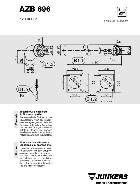
Abgasführung waagrecht<br />
für Brennwertgeräte<br />
Die einwandfreie Funktion ist nur<br />
gewährleistet, wenn die Installationsanleitung<br />
eingehalten wird. Änderungen<br />
vorbehalten. Der Einbau<br />
muß von einem zugelassenen Installateur<br />
erfolgen. Zur Montage<br />
des Gerätes ist die entsprechende<br />
Installationsanleitung zu beachten.<br />
Italiano<br />
Kit scarico fumi orizzontale<br />
per caldaie a condensazione<br />
Il corretto funzionamento è garantito<br />
soltanto se vengono scrupolosamente<br />
rispettate le presenti<br />
istruzioni, l’installazione deve essere<br />
affidata ad un installatore<br />
qualificato. La <strong>Junkers</strong> si riserva il<br />
diritto di effettuare tutte le modifiche<br />
che riterrà necessarie.
<strong>AZB</strong> <strong>696</strong><br />
Deutsch<br />
Seite<br />
Italiano<br />
Pagina<br />
1 Verwendung 3<br />
2 Allgemeines 3<br />
3 Montagehinweise 3<br />
4 Montage <strong>AZB</strong> <strong>696</strong> bei Abgasabführung<br />
über die Außenwand 4-5<br />
5-10 Abgasabführung über Außenwand (C 13 )<br />
bei Z.BR 7/11-25 A 6-17<br />
11 Abgasabführung waagrecht über Dach mit<br />
Dachgaube (C 13 ) bei Z.BR 7/11-25 A 18<br />
1 Utilizzo 3<br />
2 Informazioni generali 3<br />
3 Istruzioni di montaggio 3<br />
4 Montaggio <strong>AZB</strong> <strong>696</strong> con scarico<br />
a parete 4-5<br />
5-10 Montaggio <strong>AZB</strong> <strong>696</strong> con<br />
scarico diretto a parete (C 13 )<br />
per Z.BR 7/11- 25 A 6-17<br />
11 Scarico fumi orizzontale<br />
passante per abbaino (C 13 )<br />
per Z.BR 7/11- 25 A 18<br />
2 4 911
<strong>AZB</strong> <strong>696</strong><br />
1 Verwendung<br />
1 Utilizzo<br />
Deutsch<br />
Gerätetyp<br />
ZSBR 7/11-25 A<br />
ZWBR 7/11-25 A<br />
Abgaszubehör<br />
AZ <strong>696</strong><br />
Italiano<br />
con Apparecchio<br />
ZSBR 7/11-25 A<br />
ZWBR 7/11-25 A<br />
accessorio per<br />
scarico fumi<br />
AZ <strong>696</strong><br />
2 Allgemeines<br />
Bei der Abgasabführung nach C 13 ist das Abgaszubehör<br />
Bestandteil der CE-Zulassung. Aus diesem Grund<br />
dürfen nur Original-<strong>Junkers</strong>-Abgaszubehöre verwendet<br />
werden.<br />
Die Oberflächentemperatur am Frischluftrohr liegt unter<br />
85 °C. Somit sind keine Mindestabstände zu brennbaren<br />
Baustoffen erforderlich. Die Vorschriften der einzelnen<br />
Länder können hiervon abweichen und Mindestabstände<br />
zu brennbaren Baustoffen vorschreiben.<br />
3 Montagehinweise<br />
Das Abgaszubehör ist mit einer Steigung von 3 % nach<br />
außen einzubauen. In feuchten Räumen sind die Abgaszubehöre<br />
(Frischluftrohr) zu isolieren.<br />
Abgasmündung über Außenwand<br />
Installationen mit Mündungen des Doppelrohres<br />
in einen Schacht unter Erdgleiche können im<br />
Winter durch Eisbildung im Doppelrohr zu Störabschaltungen<br />
führen und sind möglichst zu vermeiden!<br />
Die maximale Abgas-/Frischlufrohrlänge beträgt 8 m. Es<br />
sind insgesamt maximal drei 90°-Krümmer zulässig.<br />
Statt einem 90°-Krümmer können auch zwei 45°-Versatzbögen<br />
verwendet werden.<br />
2 Informazioni generali<br />
Nel caso del condotto di scarico secondo C 13 l’accessorio<br />
per scarico fumi è parte integrante dell’omologazione<br />
CE. Per questo motivo è obbligatorio l’utilizzo di<br />
accessori di scarico fumi originali <strong>Junkers</strong>.<br />
La temperatura massima delle superfici esterne inferiore<br />
a 85 °C. Non è pertanto necessario rispettare distanze<br />
previste per le sostanze infiammabili. Le norme possono<br />
comunque differire e prescrivere differenti distanze minime.<br />
3 Istruzioni di montaggio<br />
L’accessorio scarico fumi deve essere installato con<br />
una pendenza verso l’esterno del 3 %, nei locali con alto<br />
tasso di umidità i condotti di aspirazione aria devono essere<br />
coibentati.<br />
Scarico fumi diretto a parete<br />
Se l’apparecchio è situato in uno scantinato con<br />
scarico verso una bocca da lupo o sotto il piano<br />
campagna, d’inverno esiste il pericolo di gelo nei<br />
condotti con conseguente spegnimento della caldaia,<br />
evitare perciò tale installazione.<br />
La lunghezza massima del condotto concentrico è di<br />
8 m, si possono utilizzare un massimo di 3 curve concentriche<br />
a 90°; due curve a 45° vengono considerate<br />
come una singola curva a 90°.<br />
4 911 3
<strong>AZB</strong> <strong>696</strong><br />
Deutsch<br />
4 Montage <strong>AZB</strong> <strong>696</strong> bei Abgasabführung<br />
über die Außenwand<br />
Hinweis: Vor dem Zusammenstecken der Abgaszubehöre,<br />
Dichtungen an den Muffen mit lösungsmittelfreiem<br />
Fett (z. B. Vaseline) leicht<br />
einfetten.<br />
Italiano<br />
4 Montaggio <strong>AZB</strong> <strong>696</strong> con scarico a<br />
parete<br />
Avvertenza: Prima di montare gli accessori scarico<br />
fumi applicare, sui raccordi e sulle guarnizioni,<br />
un velo di grasso privo di solventi<br />
(p. e. vaselina).<br />
– Schieben Sie den 90°-Doppelrohrkrümmer (B1.3)<br />
unter leichtem Drehen bis zum Anschlag auf den Anschlußstutzen<br />
des Gerätes (Bild 4 ).<br />
– Ermitteln Sie die Länge L der Wanddurchführung<br />
(B1.1). Beachten Sie, daß der Abstand von der Außenwand<br />
zum Abgasrohrende der Wanddurchführung<br />
(B1.1) berücksichtigt ist (Bild 2 ).<br />
– Stellen Sie den Mauerdurchbruch her. Beachten Sie<br />
hierbei die 3 %ige Steigung des Abgasrohres (Ø D<br />
siehe Bild 3 und Tabelle 1).<br />
– Stecken sie die innere Abdeckplatte (B1.2) auf die<br />
Wanddurchführung (B1.1) (Bild 4 ). Erfolgt die<br />
Frischluft-/Abgasführung von wandhängenden Geräten<br />
aus seitlich, ohne Versatz nach vorne, muß die<br />
Abdeckplatte gekürzt werden.<br />
– Wanddurchführung (B1.1) von innen nach außen<br />
durch den Mauerdurchbruch führen und anschließend<br />
unter leichtem Drehen in die Muffe des 90°-<br />
Doppelrohrkrümmers (B1.3) schieben. Achten Sie<br />
darauf, daß die Frischluftansaugschlitze der Wanddurchführung<br />
(B1.1) nach unten zeigen (Bild 4 ).<br />
– Stecken sie die äußere Abdeckplatte (B1.2) auf die<br />
Wanddurchführung (B1.1) (Bild 4 ).<br />
– Bohren sie die Befestigungslöcher für die beiden Abdeckplatten<br />
und befestigen Sie diese mit Dübeln und<br />
Schrauben (B1.5) (Bild 4 ).<br />
– Drücken Sie das Schutzgitter leicht zusammen und<br />
stecken Sie es in die Endmuffe der Wanddurchführung<br />
(B1.1) (Bild 4 ).<br />
Mauerdicke<br />
S in cm<br />
Wanddurchbruch<br />
Ø D in mm<br />
Attenzione:<br />
Per installazioni con condotti concentrici, prima di montare<br />
l’accessorio sopracitato, installare sull’apparecchio<br />
l’accessorio <strong>AZB</strong> 682.<br />
– Montare la curva concentrica a 90° (B1.3) sulla caldaia,<br />
ruotandola leggermente fino alla battuta (fig. 4 ).<br />
– Determinare la lunghezza L del condotto, facendo attenzione<br />
alla sporgenza che deve mantenere il condotto<br />
(B1.1) all’esterno della parete (fig. 2 ).<br />
– Effettuare il foro nel muro (Ø D) vedi fig. 3 e<br />
tabella 1, facendo attenzione che il condotto abbia<br />
una pendenza del 3 %.<br />
– Inserire il rosone interno (B1.2) sul condotto (B1.1)<br />
(fig. 4 ), se il condotto viene installato lateralmente<br />
all'apparecchio il rosone potrebbe essere più grande<br />
del dovuto, in questo caso tagliarlo adeguatamente<br />
per posarlo alla parete.<br />
– Mettere il condotto di scarico (B1.1) nel foro e inserirlo<br />
nella curva concentrica a 90° (B1.3). Fare attenzione<br />
che le feritoie d’areazione del condotto (B1.1)<br />
siano rivolte verso il basso (fig. 4 ).<br />
– Mettere il rosone esterno (B1.2) sul condotto di scarico<br />
(B1.1) (fig. 4 ).<br />
– Praticare i fori di fissaggio per entrambi i rosoni e fissarli<br />
mediante viti e tasselli (B1.5) (fig. 4 ).<br />
– Inserire la griglia di protezione sul condotto (B1.1)<br />
stringendola leggermente (fig. 4 ).<br />
Spessore del muro<br />
S in cm<br />
17,5-22 150<br />
Diametro del foro<br />
Ø D in mm<br />
17,5-22 150<br />
24-28 160<br />
24-28 160<br />
36-40 170<br />
36-40 170<br />
50 180<br />
50 180<br />
Tabella 1<br />
Tabelle 1<br />
Legende 4 :<br />
B1.1 Wanddurchführung<br />
B1.2 Abdeckplatten<br />
B1.3 Doppelrohrkrümmer<br />
Legenda 4 :<br />
B1.1 Condotto scarico fumi<br />
B1.2 Rosoni<br />
B1.3 Curva concentrica a 90°<br />
4 4 911
2<br />
<strong>AZB</strong> <strong>696</strong><br />
160<br />
200<br />
10<br />
3<br />
min<br />
150<br />
S<br />
ø125<br />
øD<br />
3%<br />
ØD<br />
4498-3.1S<br />
B1.1<br />
B1.2<br />
6 720 604 911-03.1O<br />
4<br />
B1.2<br />
B1.3<br />
3%<br />
B1.2<br />
B1.1<br />
B1.5<br />
6 720 604 911-04.1O<br />
4 911 5
Deutsch<br />
5 Abgasabführung über Außenwand<br />
(C 13 ) bei Z.BR 7/11-25 A<br />
– Einbaumaße ZSBR/ZWBR siehe Bild 5 und 6 .<br />
Gas Maß G Ø D<br />
DN 20 1085 mm Ø D siehe Bild 3 und Tabelle 1<br />
– Einbaumaße ZSBR mit Brauchwasserspeicher<br />
ST 120/160-1 E siehe Bild 7 .<br />
ST 120-1 E<br />
ST 160-1 E<br />
Y A<br />
2160 mm<br />
X 60 mm 0 mm<br />
Italiano<br />
<strong>AZB</strong> <strong>696</strong><br />
5 Montaggio <strong>AZB</strong> <strong>696</strong> con<br />
scarico diretto a parete (C 13 )<br />
per Z.BR 7/11- 25 A<br />
Attenzione:<br />
Per installazioni con condotti concentrici, prima di montare<br />
l’accessorio sopracitato, installare sull’apparecchio<br />
l’accessorio <strong>AZB</strong> 682.<br />
– Misure d’installazione ZSBR/ZWBR vedi fig. 5 + 6 .<br />
Gas Dimensione G Ø D<br />
DN 20 1085 mm Ø D vedi fig. 3 e tabella 1<br />
– Misure d’installazione ZSBR con bollitore<br />
ST 120/160-1 E vedi fig. 7 .<br />
Y A<br />
ST 120-1 E<br />
2160 mm<br />
ST 160-1 E<br />
X 60 mm 0 mm<br />
6 4 911
<strong>AZB</strong> <strong>696</strong><br />
5<br />
6<br />
3%<br />
ØD<br />
ø125<br />
ø82<br />
Ø125<br />
85<br />
10<br />
G<br />
950<br />
850<br />
850<br />
512<br />
6 720 604 911-05.1O<br />
360<br />
376,5<br />
min 800<br />
4498-9.1S<br />
7<br />
3%<br />
Ø125<br />
Ø80<br />
85<br />
240<br />
400<br />
512<br />
850<br />
950<br />
360<br />
376,5<br />
850<br />
10<br />
YA<br />
13<br />
ST 120-1E 500<br />
ST 160-1E 550<br />
1150<br />
ST 120-1E 500<br />
ST 160-1E 550<br />
920<br />
935<br />
X<br />
6 720 604 911-07.1O<br />
4 911 7
Deutsch<br />
6 Abgasabführung über Außenwand<br />
(C 13 ) bei Z.BR 7/11-25 A<br />
– Einbaumaße ZSBR mit Brauchwasserspeicher<br />
ST 75 siehe Bild 8 .<br />
Gas Maß G Ø D<br />
DN 20 1085 mm Ø D siehe Bild 3 und Tabelle 1<br />
Italiano<br />
<strong>AZB</strong> <strong>696</strong><br />
6 Condotto di scarico diretto a<br />
parete (C 13 ) per Z.BR 7/11-25 A<br />
Attenzione:<br />
Per installazioni con condotti concentrici, prima di montare<br />
l’accessorio sopracitato, installare sull’apparecchio<br />
l’accessorio <strong>AZB</strong> 682.<br />
– Misure d’installazione ZSBR con bollitore ST 75 E<br />
vedi fig. 8 .<br />
Gas Dimensione G Ø D<br />
DN 20 1085 mm Ø D vedi fig. 3 e tabella 1<br />
8 4 911
<strong>AZB</strong> <strong>696</strong><br />
8<br />
3%<br />
ØD<br />
Ø125<br />
Ø125<br />
G<br />
Ø82<br />
min<br />
100<br />
15<br />
min<br />
100<br />
85<br />
950<br />
850<br />
ST 75<br />
10<br />
850<br />
512<br />
440<br />
360<br />
376,5<br />
967<br />
450<br />
min 920<br />
6 720 604 911-08.1O<br />
4 911 9
Deutsch<br />
7 Abgasabführung über Außenwand<br />
(C 13 ) bei Z.BR 7/11-25 A<br />
• Abgasführung seitlich, ohne Versatz nach vorne siehe<br />
Bild 9 und 10.<br />
Die innere Abdeckplatte muß gekürzt werden.<br />
• Die maximale Länge L von 8 m darf nicht überschritten<br />
werden (Bild 10).<br />
Italiano<br />
<strong>AZB</strong> <strong>696</strong><br />
7 Condotto di scarico diretto a<br />
parete (C 13 ) per Z.BR 7/11-25 A<br />
Attenzione:<br />
Per installazioni con condotti concentrici, prima di montare<br />
l’accessorio sopracitato, installare sull’apparecchio<br />
l’accessorio <strong>AZB</strong> 682.<br />
• Scarico orizzontale senza deviazioni (fig. 9 + 10), se<br />
il condotto viene installato lateralmente all'apparecchio<br />
il rosone potrebbe essere più grande del dovuto,<br />
in questo caso tagliarlo adeguatamente per posarlo<br />
alla parete.<br />
• La lunghezza massima L è di 8 metri (fig. 10).<br />
10 4 911
<strong>AZB</strong> <strong>696</strong><br />
9<br />
B1.1<br />
B1.3<br />
210<br />
min 100<br />
360<br />
Ø125<br />
15<br />
85<br />
B1.2 160<br />
min 100<br />
512<br />
L<br />
6 720 604 911-09.1O<br />
9 :<br />
B1: <strong>AZB</strong> <strong>696</strong><br />
L max = 1020 mm<br />
10<br />
B1.1<br />
210<br />
15<br />
B2<br />
B1.3<br />
min 100<br />
Ø125<br />
B1.2<br />
LF<br />
85<br />
360<br />
160<br />
512<br />
L<br />
6 720 604 911-10.1O<br />
10:<br />
B1: <strong>AZB</strong> <strong>696</strong><br />
B2: AZ 604, 605, 606<br />
L max = 8 m<br />
B2<br />
<strong>AZB</strong> 604<br />
<strong>AZB</strong> 605<br />
<strong>AZB</strong> 606<br />
LF<br />
490 mm<br />
990 mm<br />
1990 mm<br />
4 911 11
Deutsch<br />
8 Abgasabführung über Außenwand<br />
(C 13 ) bei Z.BR 7/11-25 A<br />
• Abgasführung seitlich, mit Versatz nach vorne siehe<br />
Bild 11 und 12 .<br />
• Die maximale Länge L von 8 m darf nicht überschritten<br />
werden (Bild 12).<br />
Italiano<br />
<strong>AZB</strong> <strong>696</strong><br />
8 Condotto di scarico diretto a<br />
parete (C 13 ) per Z.BR 7/11-25 A<br />
Attenzione:<br />
Per installazioni con condotti concentrici, prima di montare<br />
l’accessorio sopracitato, installare sull’apparecchio<br />
l’accessorio <strong>AZB</strong> 682.<br />
• Scarico orizzontale con deviazione fig. 11 + 12.<br />
• La lunghezza massima L è di 8 metri (fig. 12).<br />
12 4 911
11<br />
<strong>AZB</strong> <strong>696</strong><br />
B6.2 B6.1 B1.3 min 100<br />
B1.1<br />
210<br />
165<br />
230<br />
Ø125<br />
85<br />
360<br />
B1.2<br />
max 950<br />
512<br />
160<br />
L<br />
6 720 604 911-11.1O<br />
11:<br />
B1: <strong>AZB</strong> <strong>696</strong><br />
B6: <strong>AZB</strong> 608<br />
L max = 1210 mm<br />
12<br />
B2<br />
B1.3<br />
min 100<br />
B1.1<br />
210<br />
165<br />
230<br />
85<br />
Ø125<br />
LF<br />
360<br />
B1.2<br />
160<br />
max 950<br />
B6.2<br />
B6.1<br />
512<br />
L<br />
6 720 604 911-12.1O<br />
12:<br />
B1: <strong>AZB</strong> <strong>696</strong><br />
B2: AZ 604, 605, 606<br />
B6: <strong>AZB</strong> 608<br />
L max = 8 m<br />
B2<br />
<strong>AZB</strong> 604<br />
<strong>AZB</strong> 605<br />
<strong>AZB</strong> 606<br />
LF<br />
490 mm<br />
990 mm<br />
1990 mm<br />
4 911 13
Deutsch<br />
9 Abgasabführung über Außenwand<br />
(C 13 ) bei Z.BR 7/11-25 A<br />
• Abgasführung nach hinten mit oder ohne seitlichen<br />
Versatz siehe Bild 13 und 14.<br />
• Die maximale Länge L von 8 m darf nicht überschritten<br />
werden (Bild 14).<br />
Italiano<br />
<strong>AZB</strong> <strong>696</strong><br />
9 Condotto di scarico diretto a<br />
parete (C 13 ) per Z.BR 7/11-25 A<br />
Attenzione:<br />
Per installazioni con condotti concentrici, prima di montare<br />
l’accessorio sopracitato, installare sull’apparecchio<br />
l’accessorio <strong>AZB</strong> 682.<br />
• Condotto di scarico posteriore con o senza deviazioni<br />
(fig. 13 + 14).<br />
• La lunghezza massima L è di 8 metri (fig. 14).<br />
14 4 911
<strong>AZB</strong> <strong>696</strong><br />
13<br />
B1.2<br />
Ø125<br />
160<br />
210<br />
B1.1<br />
L<br />
min 100<br />
85<br />
110<br />
B1.3<br />
360<br />
512<br />
6 720 604 911-13.1O<br />
11:<br />
B1: <strong>AZB</strong> <strong>696</strong><br />
L max = 1020 mm<br />
14<br />
B1.2<br />
Ø125<br />
160<br />
210<br />
B1.1<br />
L2<br />
min 100<br />
110<br />
LF<br />
85<br />
B3<br />
B2<br />
512<br />
B1.3<br />
360<br />
L1<br />
6 720 604 911-14.1O<br />
12:<br />
B1: <strong>AZB</strong> <strong>696</strong><br />
B2: AZ 604, 605, 606<br />
B3: <strong>AZB</strong> 607<br />
L = L 1 + L 2<br />
L max = 8 m<br />
B2<br />
<strong>AZB</strong> 604<br />
<strong>AZB</strong> 605<br />
<strong>AZB</strong> 606<br />
LF<br />
490 mm<br />
990 mm<br />
1990 mm<br />
4 911 15
Deutsch<br />
10 Abgasabführung über Außenwand<br />
(C 13 ) bei Z.BR 7/11-25 A<br />
• Die maximale Länge L von 8 m darf nicht überschritten<br />
werden (Bild 15).<br />
Italiano<br />
<strong>AZB</strong> <strong>696</strong><br />
10 Condotto di scarico diretto a<br />
parete (C 13 ) per Z.BR 7/11-25 A<br />
Attenzione:<br />
Per installazioni con condotti concentrici, prima di montare<br />
l’accessorio sopracitato, installare sull’apparecchio<br />
l’accessorio <strong>AZB</strong> 682.<br />
• La lunghezza massima L è di 8 metri (fig. 15).<br />
16 4 911
<strong>AZB</strong> <strong>696</strong><br />
15<br />
L1<br />
B1.1 min 100<br />
B3<br />
LF<br />
85<br />
LF<br />
360<br />
B2<br />
512<br />
B1.1<br />
210<br />
B2<br />
L2<br />
Ø125<br />
B1.2<br />
160<br />
L3<br />
B3<br />
6 720 604 911-15.1O<br />
11:<br />
B1: <strong>AZB</strong> <strong>696</strong><br />
B2: AZ 604, 605, 606<br />
B3: <strong>AZB</strong> 607<br />
L max = L 1 + L 2 + L 3 = 8 m<br />
L 3 max = 1020 mm<br />
B2<br />
<strong>AZB</strong> 604<br />
<strong>AZB</strong> 605<br />
<strong>AZB</strong> 606<br />
LF<br />
490 mm<br />
990 mm<br />
1990 mm<br />
4 911 17
Deutsch<br />
11 Abgasabführung waagrecht<br />
über Dach mit Dachgaube (C 13 )<br />
bei Z.BR 7/11-25 A<br />
• Die maximale Länge L von 8 m darf nicht überschritten<br />
werden (Bild 16 + 17).<br />
Italiano<br />
<strong>AZB</strong> <strong>696</strong><br />
11 Scarico fumi orizzontale<br />
passante per abbaino (C 13 )<br />
per Z.BR 7/11- 25 A<br />
Attenzione:<br />
Per installazioni con condotti concentrici, prima di montare<br />
l’accessorio sopracitato, installare sull’apparecchio<br />
l’accessorio <strong>AZB</strong> 682.<br />
• La lunghezza massima L è di 8 metri (fig. 16 + 17).<br />
18 4 911
<strong>AZB</strong> <strong>696</strong><br />
16<br />
L<br />
210<br />
B1.3<br />
3%<br />
19<br />
240<br />
400<br />
B1.1<br />
Ø125<br />
160<br />
min 1172<br />
1020<br />
850<br />
950<br />
>30°<br />
512<br />
6 720 604 911-16.1O<br />
16:<br />
B1: <strong>AZB</strong> <strong>696</strong><br />
19: AZ 122/123<br />
L max = 1020 mm<br />
17<br />
L<br />
210<br />
B1.3<br />
LF<br />
19<br />
240<br />
400<br />
3%<br />
B2<br />
˘125<br />
B1.1<br />
B1<br />
1020<br />
˘125<br />
160<br />
850<br />
950<br />
>30°<br />
6 720 604 911-17.1O<br />
512<br />
17:<br />
B1: <strong>AZB</strong> <strong>696</strong><br />
B2: AZ 604, 605, 606<br />
19: AZ 122/123<br />
L max = 8 m<br />
B2<br />
<strong>AZB</strong> 604<br />
<strong>AZB</strong> 605<br />
<strong>AZB</strong> 606<br />
LF<br />
490 mm<br />
990 mm<br />
1990 mm<br />
4 911 19
<strong>AZB</strong> <strong>696</strong><br />
Deutschland<br />
Robert Bosch GmbH<br />
Geschäftsbereich <strong>Junkers</strong><br />
D-73243 Wernau, Postfach 1309<br />
☎ 0 71 53 / 30 61<br />
España Robert Bosch Comercial Española S. A.<br />
Hnos. Garcia Noblejas, 19, Apartado 50.488<br />
28037 Madrid<br />
☎ 91 / 3 67 40 00<br />
Italia Robert Bosch Industriale e Commerciale S. p. A.<br />
Settore <strong>Junkers</strong><br />
20149 Milano, Via M.A. Colonna 35<br />
☎ 02 / 3 69 61, Fax 02 / 3 69 65 61<br />
Nederland<br />
Österreich<br />
Robert Bosch B.V.<br />
Divisie <strong>Junkers</strong><br />
Postbus 502<br />
2130 Am Hoofddorp<br />
☎ 0 23 / 5 65 67 00, Fax 0 23 / 5 65 67 11<br />
Robert Bosch AG<br />
Hüttenbrennergasse 5<br />
A-1011 Wien<br />
☎ 02 22 / 79 72 20<br />
België/Belgique N. V. SERVICO S. A.<br />
Kontichsesteenweg 17<br />
B-2630 Aartselaar<br />
☎ 03 / 8 87 20 60, Fax 03 / 8 77 01 29<br />
Danmark<br />
Schweiz<br />
Portugal<br />
Robert Bosch a/s<br />
Telegrafvej 1<br />
DK-2750 Ballerup<br />
☎ 44 68 68 68, Fax 44 97 97 63<br />
A. Brennwald AG<br />
Dammstraße 12<br />
CH-8810 Horgen<br />
☎ 1 / 7 27 91 91, Fax 1 / 7 27 91 99<br />
Vulcano<br />
Urb. do Falcão Lote 502 Pontinha<br />
1675 Lisboa<br />
☎ 01-478 81 20, Fax 01-479 30 22<br />
20 4 911