Frischwasser-Modul FriWa für die Trinkwasser-Erwärmung nach ...
Frischwasser-Modul FriWa für die Trinkwasser-Erwärmung nach ...
Frischwasser-Modul FriWa für die Trinkwasser-Erwärmung nach ...

Create successful ePaper yourself
Turn your PDF publications into a flip-book with our unique Google optimized e-Paper software.
<strong>Frischwasser</strong>-<strong>Modul</strong> <strong>FriWa</strong><br />
<strong>für</strong> <strong>die</strong> <strong>Trinkwasser</strong>-<strong>Erwärmung</strong><br />
<strong>nach</strong> dem Durchlauferhitzer-Prinzip<br />
Montage- und Be<strong>die</strong>nungs- Anleitung<br />
<strong>FriWa</strong> mit Zirkulations-Pumpe (optional),<br />
vordere Isolierung demontiert<br />
<strong>FriWa</strong>,<br />
Isolierung geschlossen
Inhaltsverzeichnis:<br />
• Sicherheits-Hinweise S. 2<br />
• Schema der Anlagenhydraulik S. 3<br />
Montageanleitung<br />
• Tipps und Tricks S. 4<br />
• Reihenfolge der Arbeitsschritte S. 4<br />
• Wandmontage, Anschluss-Schema S. 5<br />
• Elektrotechnischer Anschluss S. 6<br />
Inbetriebnahme<br />
• Füllen und Spülen S. 6<br />
• Einstellen der gewünschten Brauchwasser-Temperatur S. 7<br />
• Zapfleistungen / Zapfmenge / Entnahme-Leistung S. 7<br />
• Zirkulations-Betrieb (optional) S. 7<br />
• Schwerkraftbremsen S. 8<br />
Technische Daten<br />
• Lieferumfang S. 9<br />
• Technische Daten S. 10<br />
Sicherheits-Hinweise:<br />
Lesen Sie bitte <strong>die</strong> folgenden Hinweise zur Montage und Inbetriebnahme genau durch, bevor Sie das<br />
<strong>Frischwasser</strong>-<strong>Modul</strong> in Betrieb nehmen. Dadurch vermeiden Sie Schäden am <strong>Modul</strong> und Ihrer Anlage,<br />
<strong>die</strong> durch unsachgemäßen Umgang entstehen könnten.<br />
Die bestimmungswidrige Verwendung sowie unzulässige Änderungen bei der Montage und an der<br />
Konstruktion führen zum Ausschluss jeglicher Haftungsansprüche.<br />
Folgende Regeln der Technik sind - neben länderspezifischen Richtlinien - besonders zu beachten:<br />
DIN 1988 Technische Regeln <strong>für</strong> <strong>die</strong> <strong>Trinkwasser</strong>installation<br />
DIN 4708 Zentrale Warmwassererwärmungsanlagen<br />
DIN 4751 Wasserheizungsanlagen<br />
DIN 4753 Wassererwärmer und Wassererwärmungsanlagen <strong>für</strong> Trink- und Betriebswasser<br />
DIN 4757 Sonnenheizungs- und solarthermische Anlagen<br />
DIN 18380 Heizungs- und Brauchwasseranlagen<br />
DIN 18381 Gas-, Wasser- und Abwasserinstallationsarbeiten<br />
DIN 18382 Elektrische Kabel- und Leitungsanlagen in Gebäuden<br />
PrEN 12975 Thermische Solaranlagen und ihre Bauteile<br />
PrEN 12976 Thermische Solaranlagen und ihre Bauteile, Vorgefertigte Anlagen<br />
PrEN 12977 Thermische Solaranlagen und ihre Bauteile, Kundenspez. gefertigte Anlagen<br />
VDE 0100 Errichtung elektrischer Betriebsmittel<br />
VDE 0185 Allgemeines <strong>für</strong> das Errichten von Blitzschutzanlagen<br />
VDE 0190 Hauptpotentialausgleich von elektrischen Anlagen<br />
2/59
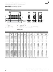
Schematische Darstellung der Anlagenhydraulik:<br />
Umschaltventil<br />
<strong>für</strong> optimale Einschichtung<br />
in den Pufferspeicher<br />
Zirkulation<br />
Verrohrung bauseits,<br />
Zirkulations-Anschluss optional,<br />
(auch <strong>nach</strong>rüstbar)<br />
Anschluss-Schema <strong>FriWa</strong> mit Zirkulations-Pumpe,<br />
Umschaltventil, Brauchwasser-Anschluss-Gruppe, Absperrungen<br />
direkt am Speicher und Schmutzfänger (Sekundärseite) sind<br />
bauseits beizustellen.<br />
Die Ausstattung mit Zirkulations-Pumpe ist optional.<br />
Ein Schmutzfänger auf der Primärseite verringert <strong>die</strong><br />
mögliche Übertragungsleistung! Die Primärpumpe ist dann<br />
gegen eine Pumpe mit größerer Leistung auszutauschen!<br />
3/59
Montageanleitung<br />
Tipps und Tricks:<br />
Für <strong>die</strong> Montage des <strong>Frischwasser</strong>-<strong>Modul</strong>s benötigen Sie (außer der <strong>FriWa</strong>):<br />
- an Werkzeug: Wasserwaage, Zollstock (Gliedermaßstab), Bohrmaschine mit 10 mm Steinbohrer<br />
(bei Montage im Mauerwerk), Gabelschlüssel: 13er - <strong>für</strong> <strong>die</strong> Befestigungsschrauben, 31er und 37er<br />
zum Gegenhalten bei der Rohrmontage und ggf. zum Nachziehen der Überwurf-Muttern,<br />
- eine 2. Person zur Montage der Station an der Wand.<br />
Sicherheits-Einrichtung – bitte beachten:<br />
Das <strong>Frischwasser</strong>-<strong>Modul</strong> ist mit einem Membran-Sicherheitsventil ¾“x1“ ausgestattet, das den<br />
einschlägigen Vorschriften entspricht. Folgende Hinweise sind <strong>für</strong> <strong>die</strong> Montage und den Betrieb zu<br />
berücksichtigen:<br />
• Die Wirksamkeit des Ventils darf durch Absperrungen nicht beeinträchtigt oder unwirksam<br />
gemacht werden!<br />
• Schmutzfänger oder andere Verengungen sind zwischen dem Platten-Wärmetauscher und dem<br />
Sicherheitsventil unzulässig!<br />
• Der Durchmesser der Abblasleitung muss dem Durchmesser des Ventilaustrittes entsprechen; <strong>die</strong><br />
maximale Länge darf 2 m nicht überschreiten; mehr als 2 Bögen sind unzulässig. Bei Überschreitung<br />
<strong>die</strong>ser Maximalwerte (2 Bögen, 2m Leitung) ist <strong>für</strong> <strong>die</strong> Abblasleitung <strong>die</strong> nächst größere<br />
Dimension zu wählen. Es ist jedoch auch hier zu beachten, dass mehr als 3 Bögen und 4 m<br />
Leitungslänge unzulässig sind.<br />
• Wird <strong>die</strong> Abblasleitung in eine Ablaufleitung mit Trichter geführt, so muss <strong>die</strong> Dimension der<br />
Ablaufleitung mindestens den doppelten Querschnitt des Ventileintritts haben. Ferner ist darauf<br />
zu achten, dass <strong>die</strong> Abblasleitung mit Gefälle verlegt wird; <strong>die</strong> Mündung muss offen und<br />
beobachtbar sein und so geführt werden, dass Personen beim Abblasen nicht gefährdet werden.<br />
Reihenfolge der Arbeitsschritte:<br />
- Festlegung des Einbauplatzes <strong>für</strong> <strong>die</strong> Station – möglichst in der Nähe des Pufferspeichers. Die<br />
<strong>FriWa</strong> montieren (siehe Wandmontage).<br />
- Verrohrung gemäß der einschlägigen Vorschriften herstellen (Heizungsseitig mindestens in DN25)<br />
und das <strong>Frischwasser</strong>-<strong>Modul</strong> anschließen (siehe Anschluss-Schema). Zur Vermeidung von<br />
elektrochemischer Korrosion ist bei Verwendung von verzinkten Leitungen und Fittingen <strong>die</strong><br />
Installationsfolge zu beachten! Alle Überwurfmuttern und Verschraubungen fest anziehen.<br />
- Elektrotechnischen Anschluss der Anlage vornehmen lassen (siehe Elektrotechnischer<br />
Anschluss). Die einschlägigen Vorschriften (VDE 0100 etc.) dabei beachten.<br />
- Druckprüfung und Inbetriebnahme der Anlage (siehe Inbetriebnahme).<br />
4/59
Wandmontage <strong>FriWa</strong>:<br />
1. Vorbereitende Arbeiten:<br />
Den Standort der Station festlegen - in der<br />
Nähe des Pufferspeichers (max. Länge der<br />
Rohrleitung primär- / Heizungs-seitig =<br />
insgesamt 4m!).<br />
Die Bohrloch-Abstände gemäß nebenstehender<br />
Zeichnung auf <strong>die</strong> Wand übertragen.<br />
2. Die Bohrlöcher anzeichnen, Löcher bohren,<br />
beiliegende Dübel einstecken.<br />
3. Das linke Teil der vorderen Isolierung<br />
abziehen. Die Station kann dann direkt<br />
montiert werden!<br />
4. Verrohrung der Anlage gemäß <strong>nach</strong>folgendem<br />
Anschluss-Schema herstellen!<br />
Zur Vermeidung von elektrochemischer<br />
Korrosion ist bei Verwendung von<br />
verzinkten Leitungen und Fittingen <strong>die</strong><br />
Installationsfolge zu beachten! Die<br />
Armaturen sind werkseitig vormontiert,<br />
dennoch ist bei der Inbetriebnahme <strong>die</strong><br />
Dichtigkeit zu überprüfen (Druckprobe).<br />
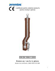
Anschluss-Schema:<br />
Loch-Bild<br />
1<br />
1 – Zulauf vom Puffer (Primärseite),<br />
Anschluss ¾“IG, Verrohrung:<br />
mindestens DN25, Ø28x1,5 mm,<br />
maximale Länge = 2m<br />
2 – Rücklauf zum Puffer (Primärseite),<br />
Anschluss ¾“IG, Verrohrung:<br />
mindestens DN25, Ø28x1,5 mm,<br />
maximale Länge = 2m<br />
3 – Kaltwasser-Eintritt (Sekundär),<br />
1“AG flachdichtend<br />
4 – Warmwasser-Austritt (Sekundär),<br />
1“AG flachdichtend<br />
5 – Warmwasser-Zirkulation – Rücklauf<br />
(sekundär), 1“AG flachdichtend<br />
Hinweis:<br />
Das <strong>Frischwasser</strong>-<br />
<strong>Modul</strong> ist zu erden.<br />
5<br />
2<br />
3 4<br />
5/59
Elektrotechnischer Anschluss<br />
Das <strong>Frischwasser</strong>-<strong>Modul</strong> ist werksseitig fertig verdrahtet. Der Anschluss an das Stromnetz (230 V/AC,<br />
50 - 60 Hz) erfolgt mit der bereits angeklemmten Netzanschlussleitung. Arbeiten an stromführenden<br />
Teilen des <strong>FriWa</strong>-<strong>Modul</strong>s dürfen ausschließlich durch eine zugelassene Fachfirma unter Beachtung der<br />
gültigen Vorschriften und der einschlägigen Normen (VDE 0100, VDE 0185, VDE 0190 etc.) erfolgen.<br />
Eine sachgemäße Erdung ist am Halteblech der <strong>FriWa</strong> vorzunehmen!<br />
Inbetriebnahme<br />
Füllen und Spülen<br />
Die Befüllung und Inbetriebnahme muss durch eine zugelassene Fachfirma erfolgen. Dabei sind <strong>die</strong><br />
Funktion und <strong>die</strong> Dichtheit der gesamten Anlage zu prüfen. Die <strong>FriWa</strong> wurde im Werk einer Druckprobe<br />
unterzogen. Dennoch soll auch <strong>die</strong> <strong>FriWa</strong> im montierten Zustand mit der gesamten Anlage der<br />
Druckprüfung unterzogen werden.<br />
Durch das langsame Öffnen der Kugelhähne und Ventile des <strong>Frischwasser</strong>-<strong>Modul</strong>s bzw. der Ventile<br />
in den Leitungen werden Druckschläge vermieden.<br />
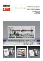
Thermo-Kugelhahn mit Flansch (6) und<br />
zusätzlich mit Schwerkraftbremse (7)<br />
6<br />
8, 8A<br />
offen<br />
geschlossen<br />
Zum Befüllen des Primär-Kreises als erstes den Kugelhahn<br />
(7) im Rücklauf zum Speicher langsam öffnen (mit<br />
einem 14er Gabel- bzw. Maulschlüssel)<br />
und in 45°-Stellung bringen – nicht vollständig<br />
öffnen - (dadurch wird <strong>die</strong> integrierte<br />
Schwerkraftbremse aufgestellt).<br />
Dann den Kugelhahn (6) im Vorlauf<br />
öffnen. Zum Entlüften des Primärkreises<br />
den Spülhahn (8) am oberen Wärmetauscher-Anschluss<br />
vorsichtig öffnen. Nachdem <strong>die</strong><br />
Dichtigkeitsprüfung erfolgreich abgeschlossen ist, soll der 7<br />
Primärkreis noch einmal entlüftet werden. Alle Kugelhähne<br />
/ Ventile im Primärkreis (auch am Speicher) vollständig<br />
öffnen. Da<strong>nach</strong> <strong>die</strong> Pumpe von Hand einschalten (Im<br />
Regler, Menü „HANDBETRIEB“) und einige Minuten<br />
zirkulieren lassen.<br />
Um den Sekundärkreis zu Füllen und Entlüften, <strong>die</strong> Kolbenventile in Fließrichtung <strong>nach</strong>einander<br />
öffnen. Zum Entlüften des Wärmetauschers den Spülhahn (8A) am oberen Wärmetauscher-<br />
Anschluss vorsichtig öffnen. Eine Warmwasser-Zapfstelle öffnen, so dass <strong>die</strong> Luft aus der Leitung<br />
entweichen kann.<br />
Die Befüllung und Spülung muss solange durchgeführt werden, bis gewährleistet ist, dass das System<br />
vollkommen entlüftet ist! Hörbare Strömungsgeräusche beim Betrieb der Umwälzpumpe(n) deuten<br />
darauf hin, dass sich noch Luft in der Anlage befindet.<br />
6/59
Einstellen der gewünschten Brauchwasser-Temperatur<br />
Die gewünschte (maximale) Warmwasser-Temperatur wird am Regler eingestellt (siehe Be<strong>die</strong>nungsanleitung<br />
zum Regler, Menü „EINSTELLWERTE“).<br />
Damit ein Verbrühen am Wasserhahn ausgeschlossen ist, soll <strong>die</strong> maximale Warmwasser-Temperatur<br />
60°C nicht übersteigen. Bereits bei 52°C ist eine dauerhaft keimfreie Wasseraufbereitung gewährleistet.<br />
Die primärseitig erforderliche Temperatur (im Pufferspeicher) ist abhängig von der gewünschten<br />
(maximalen) Warmwasser-Temperatur sowie der benötigten Zapfmenge. Die Temperatur im<br />
Pufferspeicher muss mindestens 5K über der gewünschten Warmwasser-Temperatur betragen! Als<br />
Anhaltspunkte können <strong>die</strong> in der folgenden Tabelle genannten Werte gelten.<br />
Zapfleistungen / max. Zapfmenge / Entnahme-Leistung<br />
Die mögliche Zapfleistung [l/min] am Wasserhahn ist abhängig von der im Regler eingestellten<br />
Warmwasser-Temperatur und der zur Verfügung stehenden Temperatur im Speicher.<br />
Der maximale <strong>Trinkwasser</strong>-Volumenstrom durch das FRIWA-<strong>Modul</strong> beträgt 40 l/min!<br />
Die maximalen Zapfmengen, <strong>die</strong> unten genannt werden, können auf einmal entnommen werden,<br />
wenn <strong>die</strong> oberen 200 Liter des Pufferspeichers vollständig durchgeheizt sind. Eine Nachheizung des<br />
Speichers während der Entnahme ist dabei nicht berücksichtigt.<br />
Die Entnahme-Leistung ist erforderlich, um <strong>die</strong> Wassermenge der Zapfleistung [l/min] von 10°C<br />
auf 45°C zu erwärmen.<br />
Speichertemperatur<br />
50 °C<br />
60 °C<br />
70 °C<br />
80 °C<br />
Im Regler<br />
eingestellte<br />
WW-Temp.<br />
Zapfleistung bei 45°C<br />
(am Wasserhahn)<br />
max. Zapfmenge<br />
(am Wasserhahn)<br />
bei 200 Liter im Speicher<br />
mit Speichertemperatur<br />
Entnahme-<br />
Leistung<br />
45 °C 20,5 l/min 155 Liter 50 kW<br />
55 °C - / - - / - - / -<br />
45 °C 31,7 l/min 240 Liter 77 kW<br />
55 °C 23,7 l/min 180 Liter 61 kW<br />
45 °C 40,0 l/min 310 Liter 99 kW<br />
55 °C 35,4 l/min 265 Liter 90 kW<br />
45 °C 40,0 l/min 370 Liter 99 kW<br />
55 °C 44,7 l/min 335 Liter 114 kW<br />
Zirkulations-Betrieb (optional)<br />
Das <strong>Frischwasser</strong>-<strong>Modul</strong> ist (optional) mit einer Zirkulationspumpe versehen.<br />
Die Zirkulationspumpe kann auch noch <strong>nach</strong>gerüstet werden (<strong>die</strong> Abschnitte „Wandmontage,<br />
Anschluss-Schema, Elektrotechnischer Anschluss sowie Inbetriebnahme“ sind dabei besonders zu<br />
beachten).<br />
Für den Betrieb der Zirkulationspumpe sind im Regler drei mögliche Betriebsarten hinterlegt (siehe<br />
auch Be<strong>die</strong>nungsanleitung zum Regler, Menü „OPTIONEN“):<br />
7/59
- impulsgesteuert (bedarfsabhängig / Anforderung), durch <strong>die</strong> kurze Betätigung einer Warmwasser-Zapfstelle<br />
(Zapfimpuls) wird <strong>die</strong> Zirkulations-Pumpe gestartet. Die Zirkulations-Pumpe läuft<br />
dann <strong>für</strong> einige Minuten (einstellbar).<br />
- zeitabhängiger Betrieb, der Betrieb der Zirkulationspumpe ist innerhalb eines frei wählbaren<br />
Zeitraumes an einer Wochenuhr einstellbar. Bei <strong>die</strong>ser Betriebsart wird <strong>die</strong> Zirkulation zu Beginn<br />
des eingestellten Zeitraumes gestartet. Die Zirkulation wird abgeschaltet <strong>nach</strong> dem Ablauf des<br />
eingestellten Zeitraumes.<br />
- zeit- / temperaturabhängig, der Betrieb der Zirkulationspumpe ist innerhalb eines frei<br />
wählbaren Zeitraumes an einer Wochenuhr einstellbar. Bei <strong>die</strong>ser Betriebsart wird <strong>die</strong> Zirkulation<br />
nur gestartet, wenn <strong>die</strong> einstellbare Minimal-Temperatur am Wärmetauscher innerhalb des<br />
Betriebszeitraumes unterschritten wird. Die Zirkulation wird abgeschaltet <strong>nach</strong> dem Erreichen der<br />
einstellbaren Solltemperatur bzw. <strong>nach</strong> dem Ablauf des eingestellten Zeitraumes.<br />
Im Auslieferungszustand ist <strong>die</strong> Zirkulation (siehe Be<strong>die</strong>nungsanleitung zum Regler,<br />
Menü „OPTIONEN“) auf „NEIN“ (Aus) voreingestellt. Bei montierter Zirkulation muss <strong>die</strong><br />
Betriebsart zwingend gewählt und eingestellt werden.<br />
Eine Zirkulations-Temperatur über 55°C begünstigt <strong>die</strong> Verkalkung des Wärmetauschers.<br />
Eine keimfreie Wasseraufbereitung ist bei Zirkulations-Temperaturen unter 50°C nicht<br />
mehr gegeben !<br />
Schwerkraftbremsen<br />
Der Primärkreis (Heizungskreis) ist mit einer Schwerkraftbremse<br />
im Thermo-Kugelhahn (7) ausgestattet, um eine<br />
unerwünschte Eigenzirkulation (Schwerkraft-Zirkulation)<br />
sicher zu verhindern.<br />
Zum Befüllen, Entlüften und Spülen der Anlage muss <strong>die</strong><br />
Schwerkraftbremse geöffnet sein.<br />
Das geschieht, in dem der Thermo-<br />
Kugelhahn (7) halb geöffnet wird<br />
(mit einem 14ner Gabel- bzw. Maulschlüssel).<br />
Die Kugel des Kugelhahnes<br />
drückt <strong>die</strong> Schwerkraftbremse<br />
auf.<br />
9<br />
Für den Betrieb der Anlage müssen alle Kugelhähne und<br />
Ventile komplett geöffnet sein.<br />
Im Anschluss der Zirkulationsleitung (T-Stück, 9) ist eine<br />
Einlegsperre als Rückflußverhinderer eingebaut. So ist<br />
sicher gestellt, das bei der Warmwasser-Entnahme keine<br />
Kurzschluss-Strömung über <strong>die</strong> Zirkulations-Leitung<br />
entstehen kann.<br />
7<br />
Frage: Entlüftung des Zirkul-stranges = ?????<br />
8/59
Lieferumfang <strong>FriWa</strong>:<br />
Pos. Art.-Nr. Beschreibung<br />
P1 G9643 Kugelhahn ¾“ mit Flansch<br />
P2 E12319MO Wilo-Pumpe ST 20/6-3<br />
P3 B53301 Rohr I, Primär, <strong>FriWa</strong><br />
P4 G6402 Anschluss-Kreuzstück DN20<br />
P5 2260 KFE-Hahn<br />
P6 E131210 Temperatur-Sensor TWW<br />
P7 2055 MS-Überwurf-Mutter 1“IG<br />
P8 E21010 Stopfen ½“, selbstdichtend<br />
P9 B53300 Rohr II, Primär, <strong>FriWa</strong><br />
P10 B9643FRIWA<br />
Kugelhahn ¾“ mit Flansch,<br />
mit Schwerkraftbremse (SKB)<br />
Zirkulation (Z2 - Z5, Optional)<br />
Pos. Art.-Nr.<br />
Primär-Kreis<br />
Beschreibung<br />
Z1<br />
E21004 oder Kappe 1“ (ohne Zirkulation)<br />
10121 Einlegsperre ¾“ zu F=½“<br />
Z2 B53303 Rohr I, Zirkulation, <strong>FriWa</strong><br />
Z3 E12303 Wilo-Pumpe Z 20/1-1<br />
Z4 B53304 Rohr II, Zirkulation, <strong>FriWa</strong><br />
Z5 G2002 Kolbenventil DN20, 2x 1”AG<br />
Pos. Art.-Nr. Beschreibung<br />
S1 G2002 Kolbenventil DN20, 2x 1”AG<br />
S2 2055 MS-Überwurf-Mutter 1“IG<br />
S3 G6403 Flanschmuffe 1“IG x ¾“F<br />
S4 G6402 Anschluss-Kreuzstück DN20<br />
S5 2260 KFE-Hahn<br />
S6 E131210 Temperatur-Sensor TWW<br />
S7 E21010 Stopfen ½“, selbstdichtend<br />
S8 B6412 Flow Pipe-Set <strong>FriWa</strong><br />
S9 E22631 T-Stück 1“, flachdichtend<br />
S10 B53302 Rohr, Sekundär, <strong>FriWa</strong><br />
S11 G52551 Konter-T, 1“A x ¾“A x ¾“F<br />
S12 E101016<br />
Membran-Sicherheitsventil<br />
¾“ x 1“, 6 bar<br />
S13 B53129 Satz Rohr-Halteschellen<br />
PWT E11730<br />
Platten-Wärmetauscher, Typ1,<br />
mit 30 Platten<br />
Ohne Bild<br />
Pos. Art.-Nr.<br />
E13023<br />
E53147<br />
E17101<br />
Sekundär-Kreis<br />
Beschreibung<br />
<strong>FriWa</strong>-Regelung, mit Kabelsatz<br />
Halteblech <strong>für</strong> <strong>FriWa</strong><br />
Isolierungs-Satz EPP zu <strong>FriWa</strong><br />
9/59
Technische Daten:<br />
<strong>Frischwasser</strong>-<strong>Modul</strong> <strong>FriWa</strong><br />
Abmessungen: Höhe (mit Isolierung): ca. 860 mm<br />
Breite (mit Isolierung): ca. 560 mm<br />
Tiefe (mit Isolierung): ca. 260 mm<br />
Achsabstand / Stichmaß:<br />
90 mm (Sekundär),<br />
mit Zirkulation (optional) 2x 90 mm<br />
Rohranschlüsse:<br />
¾“ IG (Primär),<br />
1“ AG (Sekundär) flachdichtend<br />
technische Daten: Sicherheitsventil: ¾” x 1”, 6 bar<br />
Max. zulässiger Druck: 6 bar<br />
zulässige Temperatur: 2 °C bis 95 °C<br />
Materialien: Armaturen: Gehäuse: Messing<br />
Dichtungen: Teflon / EPDM<br />
Platten-Wärmetauscher: Edelstahl 1.4400 / Lot: 99,99% Kupfer<br />
Rohre: Edelstahl 1.4401/04<br />
O–Ringe:<br />
EPDM / Viton<br />
Flachdichtungen:<br />
AFM 34, asbestfrei<br />
Isolierung:<br />
EPP, λ = 0,041 W/(m*K)<br />
Schwerkraftbremse: Primär, Widerstand: 800 mm WS<br />
Material:<br />
PPS / Messing – Feder VA<br />
Wichtiger Hinweis<br />
Diese Anleitung entstand mit größtmöglicher Sorgfalt und <strong>nach</strong> bestem<br />
Wissen. Die verwendeten Abbildungen haben Symbolcharakter.<br />
Wir bitten um Verständnis, das wir wegen möglicher Satz- oder<br />
Druckfehler keine Haftung <strong>für</strong> <strong>die</strong> inhaltliche Richtigkeit übernehmen<br />
können. Werden aus <strong>die</strong>ser Anleitung vermittelte Inhalte benutzt oder<br />
angewendet, so geschieht <strong>die</strong>s ausdrücklich auf das eigene Risiko des<br />
jeweiligen Anwenders. Eine Haftung des Herausgebers <strong>für</strong> unsachgemäße,<br />
unvollständige oder falsche Angaben und alle daraus eventuell<br />
entstehenden Schäden wird grundsätzlich ausgeschlossen.<br />
Technische Änderungen und Verbesserungen bleiben vorbehalten.<br />
10/59
11/59
Fresh water module „<strong>FriWa</strong>“<br />
- heat up fresh water only when you need it -<br />
User’s Manual<br />
<strong>FriWa</strong> with circulator (optional),<br />
front insulation dismantled<br />
<strong>FriWa</strong>,<br />
insulation closed<br />
12/59
Index<br />
• Security advices p. 2<br />
• Hydraulic plan p. 3<br />
Assembly instructions<br />
• Tipps and tricks p. 4<br />
• Order of work steps p. 4<br />
• Wall-fastening, connexion diagram p. 5<br />
• Electrotecnical connexion p. 6<br />
Commissioning<br />
• Filling and Purging p. 6<br />
• Setting up the desired potable water temperature p. 7<br />
• Tap potential/ tap quantity / extraction power p. 7<br />
• Circulation operation (optional) p. 7<br />
• Gravity brakes p. 8<br />
Tecnical data<br />
• Scope of delivery p. 9<br />
• Technical data p. 10<br />
Security advices:<br />
Please read carefully the following advices concerning the assembly and commissioning before<br />
putting the fresh water module into operation. This way, you will avoid damages on the module or<br />
your installation which could occur due to inappropriate handling.<br />
The use contrary to the regulations as well as any incorrect modifications during the assemby and of<br />
the construction itself will lead to the exclusion of liability. The following technical rules need to be<br />
taken into account in particular – in addition to national directives - :<br />
DIN 1988 Technical rules for potable water installation<br />
DIN 4708 Central water warming installations<br />
DIN 4751 Water heating systems<br />
DIN 4753 Water warmers and water warming systems for potable water<br />
DIN 4757 Solar heating and thermal solar installations<br />
DIN 18380 Heating systems and potable water systems<br />
DIN 18381 Gas, water and waste water installation<br />
DIN 18382 Electric cables and lines in buildings<br />
PrEN 12975 Thermal solar systems and their components<br />
PrEN 12976 Thermal solar systems and their components, prefabricated installations<br />
PrEN 12977 Thermal solar systems and their components, customer-specific installations<br />
VDE 0100 Construction of electric materials<br />
VDE 0185 General rules for the construction of lightning arresters<br />
VDE 0190 Potential equalization of electric installations<br />
13/59
Hydraulic plan:<br />
Reversing valve<br />
For an optimum charge of a<br />
buffer storage<br />
Circulation<br />
Piping on site, connection for<br />
circulation optional,<br />
(retrofittable)<br />
Connection scheme <strong>FriWa</strong> with circulation pump,<br />
Reversing valve, adaptor board for potable water, shut-off<br />
device directly on the storage and the strainer (secondary side)<br />
have to be added on site.<br />
The installation can optionally be equipped with a circulation pump.<br />
A strainer on the primary side reduces the possible<br />
transmission power!<br />
14/59
Assembly instructions<br />
Tipps and tricks:<br />
For the assembly of the fresh water module you need (apart from the <strong>FriWa</strong>):<br />
- as tools: level, folding rule, power drill with 10 mm masonry drill bit (for masonry assembly), flat<br />
wrench n°13 for the fixation screws and n°31and n° 37 in order to hold against during the<br />
assembly of the tubing and if necessary in order to retightening of the connecting nuts,<br />
- a 2 nd person for the wall assembly.<br />
Security equipment – please note:<br />
The fresh water module is provided with a membrane security valve ¾“x1“ which meets the<br />
appropriate regulations. The following advices need to be taken into consideration for the assembly<br />
and the operation:<br />
• The valve may not be impaired or rendered ineffective by blockages!<br />
• Dirt collectors or other constrictions are not permitted between the collector (field) and the safety<br />
valve.<br />
• The diameter of the blow line must equal the diameter of the valve outlet; the max. length may<br />
not exceed 2m. More than 2 bends are not permitted. If these maximum values (2 bends, 2m<br />
line) are exceeded, the next largest size must be selected for the blow line. However, it must also<br />
be noted that even with the larger size more than 3 bends and 4m line length are not permitted.<br />
• If the blow line is routed in a drain pipe with a funnel, the size of the drain pipe must be at least<br />
double that of the cross section of the valve inlet. You must also ensure that the blow line is laid<br />
at a slope; the mouth must be open and visible and routed such that the blowing process does<br />
not endanger persons.<br />
Order of work steps:<br />
- Determine the location of the system – possibly near the buffer storage. Install the <strong>FriWa</strong><br />
(see wall assembly).<br />
- Connect the pipes according to the appropriate regulations (heating side at least DN25) and<br />
connect the fresh water module (see connexion plan). In order to avoid any kind of<br />
electrochemical corrosion, you absolutely need to follow the installation order while using<br />
galvanised pipes and fittings! Tighten all the nuts and screwings.<br />
- Charge qualified personell with the electrotechnical connexion of the system. (see<br />
electrotechnical connexion). The corresponding regulations (VDE 0100 etc.) need to be<br />
respected.<br />
- Pressure test und commissioning of the system (see commissioning).<br />
15/59
Wall-fastening <strong>FriWa</strong>:<br />
5. Preparation:<br />
Determine the location of the system – near<br />
the buffer storage (max. Tube length on<br />
the primary / heating side = in total<br />
4m!). Copy the hole distances as shown in<br />
the drawing on the right side onto the wall.<br />
6. Mark the holes, drill them and insert the<br />
enclosed wall plugs.<br />
7. Remove the left part of the front insulation.<br />
The station can now be mounted<br />
directly!<br />
8. Establish the system’s tubing according to<br />
the following connexion diagram!<br />
Using galvanized tubes and fittings, it<br />
is important to respect the installation<br />
order in order to avoid any kind of<br />
electrochemical corrosion! The fittings<br />
have been preassambled during the<br />
production, nevertheless, the leak<br />
tightness should be revised (pressure<br />
test) during the commissioning.<br />
Connexion diagram:<br />
Loch-Bild<br />
1<br />
1<br />
1 – supply from buffer (primary side),<br />
connexion ¾“F, tubing:<br />
at least DN25, Ø28x1,5 mm,<br />
ma. length = 2m<br />
2 – return to buffer (primary side),<br />
connexion ¾“F, tubing:<br />
at least DN25, Ø28x1,5 mm,<br />
max. length = 2m<br />
3 – cold water entry (secondary),<br />
1“M flat-sealing<br />
4 – hot water exit (secondary),<br />
1“M flat-sealing<br />
5 – hot water circulation - return<br />
(secondary), 1“M flat-sealing<br />
Advice:<br />
The fresh water module needs<br />
to be grounded.<br />
5<br />
2<br />
3 4<br />
16/59
Electrotechnical Connexion<br />
The fresh water module has been priwired. The connexion to the power supply (230 V/AC, 50 - 60<br />
Hz) is carried out with the preconnected power supply wire. Any kinds of work on the conducting<br />
parts of the <strong>FriWa</strong> module exclusively have to be carried out by an accredited specialized company<br />
and taking into account the valid regulations and corresponding standards (VDE 0100, VDE 0185,<br />
VDE 0190 etc.).<br />
Tholding plate of the <strong>FriWa</strong> system has to be grounded appropriately!<br />
Commissioning<br />
Filling and Purging<br />
The filling and commissioning have to be carried out by an accredited specialized company. The<br />
mode of operation and the leak tightness of the system need to be revised. The <strong>FriWa</strong> module has<br />
been subject to a pressure test after the production. Nevertheless, once the <strong>FriWa</strong> is mounted,<br />
another pressure test of the whole system should be carried out.<br />
By opening slowly the ball valves and valves of the fresh water module i. e. the valves inside the<br />
tubing, water hammers are avoided.<br />
Thermovalve with flange (6) and additionnally<br />
with gravity brake (7)<br />
6<br />
8, 8A<br />
open<br />
closed<br />
In order to fill the primary circuit, open slowly at first<br />
the ball valve (7) inside the return pipe to the storage<br />
(with a n°14 flat wrench) and put it into<br />
a 45° position – do not open it<br />
completely - (this way, the integrated<br />
gravity brake is opened).<br />
Then open the ball valve (6) inside the<br />
flow pipe. In order to deaerate the<br />
primary circuit, open carefully the<br />
purging valve (8) located on the upper<br />
connection of the heat exchanger. After having completed 7<br />
succesfully the pressure test, the primary circuit should be<br />
deaerated once more. Open completely all of the ball<br />
valves / valves inside the primary circuit (also those<br />
located on the storage). After that, manually switch on the<br />
pump (in the controller, menu „HANDBETRIEB“) and let it<br />
circulate for a few minutes.<br />
In order to fill and deaerate the secondary circuit, open the spool valves one after the other in the<br />
flow direction. In order to deaerate the heat exchanger, the purge valve (8A) located on the upper<br />
connection of the heat exchanger has to be opened carefully. Open a tap connection so that the air<br />
can escape from the tubing.<br />
17/59
Carry on the filling and purging until it can be guaranteed that the system is completely deaerated!<br />
Any audible flow sounds during the operation of the circulation pump(s) are evidence to that fact that<br />
there still remains air in the system.<br />
Setting up the wanted potable water temperature<br />
The wanted (max.) hot water temperature is set up on the controller (see user’s manual for the<br />
controller, menu „EINSTELLWERTE“).<br />
In order to rule out the danger of scalds on the water tap, the maximum water temperature should<br />
never exeed 60°C. Already at 52°C a steadily germfree water preparation is warranted. The<br />
necessary temperature on the primary side (inside the buffer storage) depends on the wanted (max.)<br />
hot water temperature as well as on the quantity needed. The temperature inside the buffer storage<br />
has to be at least 5K higher that the wanted hot water temperature! The coefficients mentioned in<br />
the following chart can serve as indications.<br />
Tap potential / max. tap quantity / extraction power<br />
The tap potential [l/min] depends on the hot water temperature set up on the controller and the<br />
temperature available in the storage.<br />
The maximum volume flow of potable water for the FriwWa module is 40 l/min!<br />
The max. tap quantities mentioned below can be extractesd at once if the upper 200 l of the buffer<br />
storage are entirely heated to the required temperature. A further (post-) heating of the storage<br />
during the extraction was not taken into consideration.<br />
The extraction power is necessary in order to heat up the water quantity of the tap potential<br />
[l/min] from 10°C to 45°C.<br />
storage<br />
temperature<br />
50 °C<br />
60 °C<br />
70 °C<br />
80 °C<br />
hot water<br />
temperature<br />
set up on<br />
the<br />
controller<br />
tap potential at 45°C<br />
(on the water tap)<br />
max. tap quantity<br />
(on the water tap)<br />
at 200 l inside the<br />
storage with storage<br />
temperature<br />
extraction<br />
power<br />
45 °C 20,5 l/min 155 l 50 kW<br />
55 °C - / - - / - - / -<br />
45 °C 31,7 l/min 240 l 77 kW<br />
55 °C 23,7 l/min 180 l 61 kW<br />
45 °C 40,0 l/min 310 l 99 kW<br />
55 °C 35,4 l/min 265 l 90 kW<br />
45 °C 40,0 l/min 370 l 99 kW<br />
55 °C 44,7 l/min 335 l 114 kW<br />
Circulation operation (optional)<br />
The fresh water module is (optionally) provided with a circulation pump. The circulation pump can be<br />
retrofitted (while doing this, the paragraphs “Wall fastening, Connexion Diagram, Electrotechnical<br />
Connexion and Commissioning” have to be taken into consideration in particular).<br />
For the operatoin of the circulation pump, 3 possible modes of operation can be chosen on the<br />
controller (see also the user’s manual for the controller, menu “OPTIONEN”):<br />
18/59
- pulse-driven (depending on the need / requirements), the short opening of a hot water tap (tap<br />
pulse) starts the circulation pump. The circulation pump will then run for several minutes<br />
(adjustable).<br />
- time-dependant, the operation of the circulation pump can be adjusted within an arbitrary<br />
period of time on a “week clock”. The circulation will start at the beginning of the period of time<br />
chosen. It will stop after the end of the chosen period of time.<br />
- time- / temperature -dependant, the operation of the circulation pump can be adjusted<br />
within an arbitrary period of time on a “week clock. The circulation only starts when the<br />
adjustable min. temperature on the heat exchanger is exceeded within the period of operation<br />
chosen. The circulation stops after the required temperature has been reached i.e. after the end<br />
of the chosen period of time.<br />
While delivered, the circulation (see user’s manual of the controller, menu „OPTIONEN“) is<br />
preset on „NEIN“ (OFF). After the assembly of the circulation, it is obligatory to select one<br />
mode of operation.<br />
A circulation temperature of more than 55°C favorizes the calcination of the heat<br />
exchanger. The water preparation cannot be germfree at circulation temperatures of<br />
under 50°C!<br />
Gravity brakes<br />
The primary circuit (heating circuit) is provided with a<br />
gravity brake inside the thermovalve (7), in order to<br />
securely avoid unwished recirculations (gravity circulation).<br />
For the filling, dearating and purging of the system, the<br />
gravity brake has to be open. This is<br />
done by half-opening the<br />
thermovalve (7) (with a n° 14 flat<br />
wrench). The ball of the ball valve<br />
pushed the gravity brake open.<br />
9<br />
For the operation of the system, all<br />
ball valves and valves need to be<br />
open completely<br />
An inserted lock valve – serving as return flow inhibitor –<br />
is located in the connection of the circulation tubing (T,<br />
9). This way it can be assured that possible short-circuit<br />
flows through the circulation tubing during the hot water<br />
extraction can be avoided.<br />
7<br />
Frage: Entlüftung des Zirkul-stranges = ?????<br />
19/59
Scope of delivery <strong>FriWa</strong>:<br />
Primary circuit<br />
Pos. Art. N°. Description<br />
P1 G9643 ball valve ¾“ with flange<br />
P2 E12319MO Wilo-Pump ST 20/6-3<br />
P3 B53301 tube I, primary, <strong>FriWa</strong><br />
P4 G6402 adaptor cross DN20<br />
P5 2260 valve<br />
P6 E131210 temperature sensor TWW<br />
P7 2055 union nut 1“F<br />
P8 E21010 plug ½“, self-sealing<br />
P9 B53300 tube II, primary, <strong>FriWa</strong><br />
P10 B9643FRIWA<br />
ball valve ¾“ with flange,<br />
with gravity brake<br />
Circulation (Z2 - Z5, Optional)<br />
Pos. Art. N° Description<br />
Z1<br />
E21004 or cap 1“ (without circulation)<br />
10121 inserted lock valve ¾“ to F=½“<br />
Z2 B53303 tube I, circulation, <strong>FriWa</strong><br />
Z3 E12303 Wilo-Pump Z 20/1-1<br />
Z4 B53304 tube II, circulation, <strong>FriWa</strong><br />
Z5 G2002 spool valve DN20, 2x 1”M<br />
Secondary circuit<br />
Pos. Art. N°. Description<br />
S1 G2002 spool valve DN20, 2x 1”M<br />
S2 2055 union nut 1“F<br />
S3 G6403 bush flange 1“F x ¾“M<br />
S4 G6402 adaptor cross DN20<br />
S5 2260 valve<br />
S6 E131210 temperature sensor TWW<br />
S7 E21010 plug ½“, self-sealing<br />
S8 B6412 Flow Pipe-Set <strong>FriWa</strong><br />
S9 E22631 T-piece 1“, flat-sealing<br />
S10 B53302 tube, secondary, <strong>FriWa</strong><br />
S11 G52551 counter-T, 1“M x ¾“M x ¾“F<br />
S12 E101016<br />
membrane security valve<br />
¾“ x 1“, 6 bar<br />
S13 B53129 tube clips Set<br />
PWT E11730<br />
heat exchanger, Type1, with<br />
30 plates<br />
Without illustration<br />
Pos. Art. N°. Description<br />
E13023 <strong>FriWa</strong> controle, with cables<br />
E53147 holding plate for <strong>FriWa</strong><br />
E17101 Insulation-Set EPP for <strong>FriWa</strong><br />
20/59
Technical Data:<br />
Fresh water module <strong>FriWa</strong><br />
Dimensions:<br />
Height (with insulation): approx. 860 mm<br />
Width (with insulation): approx. 560 mm<br />
Depth (with insulation): approx. 260 mm<br />
90 mm (secondary),<br />
Distance axis/ wall:<br />
with circulation (optional) 2x 90 mm<br />
Pipe connections:<br />
¾“ F (primary),<br />
1“ M (secondary) flat-sealing<br />
Technical Data: Security valve: ¾” x 1”, 6 bar<br />
Max. pressure: 6 bar<br />
Max. temperature: 2 °C to 95 °C<br />
Material: Fittings: casing: brass<br />
gaskets: Teflon / EPDM<br />
Heat exchanger: stainless steel 1.4400 / solder: 99,99% Copper<br />
Tubes: stainless steel 1.4401/04<br />
O–ringe gaskets: EPDM / Viton<br />
Flat sealing gaskets: AFM 34, asbestos-free<br />
Insulation:<br />
EPP, λ = 0,041 W/(m*K)<br />
Gravity brake: Primary, resistance: 800 mm water column<br />
Material:<br />
PPS / brass – clip VA<br />
Important note<br />
These installation and use instructions have been designed carefully to<br />
the best of our knowledge and belief. The illustrations used are to be<br />
considered exemplary.<br />
Please note that due to the risk of compositor’s errors and misprints no<br />
responsibility is accepted for the correctness as regards content. Use of<br />
information contained in these instructions is made at the user’s risk.<br />
The editor declines any liability for persons, property damage or especially<br />
direct, indirect, immediate or subsequent pecuniary loss resulting from<br />
improper, incomplete or wrong statements, details or instructions.<br />
21/59
22/59
Gruppo d’acqua sanitaria <strong>FriWa</strong><br />
Per la produzione d’acqua calda sanitaria<br />
Secondo il principio di funzionamento dello scaldaacqua<br />
istantaneo<br />
Istruzioni per l’installazione e l’uso<br />
<strong>FriWa</strong> con pompa di ricircolazione (opzionale),<br />
Parte anteriore della coibentazione smontata<br />
<strong>FriWa</strong>,<br />
Coibentazione chiusa<br />
23/59
Indice:<br />
• Istruzioni di sicurezza Pagina 2<br />
• Schema applicativo Pagina 3<br />
Istruzioni d’installazione<br />
• Consigli e trucchi del mestiere Pagina 4<br />
• Sequenze di lavoro Pagina 4<br />
• Montaggio murale, schema delle connessioni Pagina 5<br />
• Collegamento elettrotecnico Pagina 6<br />
Messa in servizio<br />
• Riempimento e spurgo Pagina 6<br />
• Messa a punto della temperatura dell’acqua sanitaria richiesta Pagina 7<br />
• Potenze di prelievo / massimo spillamento / potenza consumata Pagina 7<br />
• Servizio a circolazione Pagina 7<br />
• Valvole antitermosifone Pagina 8<br />
Caratteristiche tecniche<br />
• Volume di consegna Pagina 9<br />
• Caratteristiche tecniche Pagina 10<br />
Istruzioni di sicurezza<br />
Si prega di leggere con attenzione le seguenti istruzioni per l’installazione e la messa in servizio<br />
prima di mettere in servizio il gruppo FirWa. Così evitate guasti o danni del sistema e del vostro<br />
impianto dovuti ad un impiego improprio.<br />
Si declina ogni responsabilità per danni consecutivi a qualsiasi altra condizione d'impiego diversa da<br />
quelle previste nonché modifiche tecniche o modifiche d’installazione inammissibili.<br />
Oltre alle direttive nazionali in vigore, devono essere osservate in modo particolare le seguenti norme<br />
tecniche:<br />
DIN 1988 Regole tecniche per l’istallazione di sistemi d’acqua potabile<br />
DIN 4708 Impianti di produzione centrale d’acqua calda sanitaria<br />
DIN 4751 Impianti scaldacqua<br />
DIN 4753 Riscaldatori d’acqua e impianti scaldacqua per acqua sanitaria<br />
DIN 4757 Impianti termici ad energia solare<br />
DIN 18380 Impianti di riscaldamento e d’acqua sanitaria<br />
DIN 18381 Lavori d’installazione sistemi gas, idrici, acqua di scarico<br />
DIN 18382 Impiantistica elettrica<br />
PrEN 12975 Impianti solari termici e componenti<br />
PrEN 12976 Impianti solari termici e componenti, impianti premontati<br />
PrEN 12977 Impianti solari termici e componenti, impianti specifici per il cliente<br />
VDE 0100 Installazione di mezzi di produzione elettrici<br />
VDE 0185 Generalità relative all’installazione d’impianti di protezione contro i fulmini<br />
VDE 0190 Collegamento equipotenziale principale per impianti elettrici<br />
24/59
Schema applicativo:<br />
Valvola di commutazione<br />
Per stratificazione ottimizzata<br />
nell’accumulatore tampone<br />
Circolazione<br />
Tubazione lato edile, collegamento<br />
di circolazione opzionale, (anche<br />
potenziabile)<br />
Comprensivo dello schema di collegamento <strong>FriWa</strong> alla pompa di<br />
circolazione, della valvola di commutazione, del gruppo collegamento<br />
acqua sanitaria; non-ritorno sull’accumulatore e filtro (lato secondario)<br />
devono essere forniti dal lato edile.<br />
L’equipaggiamento comprensivo di pompa di circolazione s’intende<br />
opzionale.<br />
Aviso: l’incorporazione di un filtro nel circuito primario riduce la<br />
potenza di trasmissione! Occorre sostituire la pompa primaria con<br />
una pompa a capacità superiore!<br />
25/59
Istruzioni d’installazione<br />
Consigli e trucchi del mestiere:<br />
Per l’installazione di un gruppo per acqua sanitaria vi serve (salvo il <strong>FriWa</strong> stesso)<br />
- Come utensili: Livella a bolla d’aria, metro pieghevole, trapano con punta da trapano per pietra<br />
(10 mm) – nel caso di montaggio murale, chiave fissa: Da 13 – per le viti di fermo, da 31 e 37 per<br />
tenere fermo durante il montaggio del tubo ed eventualmente per stringere ulteriormente i dadi<br />
per raccordi,<br />
- Una seconda persona per dare una mano durante il montaggio murale della stazione,<br />
Dispositivi di sicurezza – da rispettare:<br />
Il gruppo per acqua sanitaria é equipaggiato con una valvola di sicurezza a membrana con attacco da<br />
¾’’ x 1’’ conforme ai regolamenti in vigore. Per cui è assolutamente necessario attenersi per il<br />
montaggio ed il servizio della stazione a quanto segue:<br />
• della valvola non deve essere ostacolata o risultare inefficace per blocchi<br />
• L’incorporazione di filtri o altre strozzature è vietata tra lo scambiatore di calore a piastre e la<br />
valvola di sicurezza!<br />
• Il diametro del tubo di scarico deve corrispondere a quello dell’apertura di scarico della valvola.<br />
Non eccedere la lunghezza massima di 2 m, né il numero di curve ammissibili (2 al massimo). Se<br />
fossero superati i valori massimi ammissibili (2 curve, 2 m di tubo) occorre passare alla<br />
dimensione immediatamente più grande per il condotto di scarico. Avviso: anche con la<br />
dimensione più grande occorre attenersi ai limiti prescritti (3 curve e 4 m di lunghezza per il<br />
tubo).<br />
• Nel caso di una tubazione di scarico con imbuto di scarico occorre dimensionare la tubazione in<br />
modo che la sezione traversale minima sia il doppio del foro d’ingresso della valvola. Inoltre<br />
occorre provvedere alla posa della tubazione di scarico a un dislivello. La bocca di deflusso deve<br />
essere aperta e visibile. Deve essere installato inoltre in modo da non compromettere la sicurezza<br />
di persone durante lo scarico.<br />
Sequenze di lavoro:<br />
- Determinate la posizione ossia collocazione della stazione – possibilmente in vicinanza<br />
dell’accumulatore tampone. Installare il gruppo <strong>FriWa</strong> (si veda paragrafo sul “Montaggio<br />
murale”)<br />
- Dotate il sistema delle tubazioni rispettando i regolamenti in vigore (lato riscaldamento al minimo<br />
con DN25) e collegate il gruppo d’acqua sanitaria (si veda lo schema applicativo). Per impedire<br />
la corrosione elettrochimica è obbligatorio osservare la sequenza d’installazione qualora sono<br />
utilizzate delle condutture e valvolame zincato! Serrate a fondo tutti i dadi per raccordi e<br />
raccordi a vite.<br />
- Provvedete al collegamento elettrotecnico dell’impianto (si veda il paragrafo concernente il<br />
“Collegamento elettrotecnico”) É assolutamente necessario attenersi alle norme vigenti (VDE<br />
0100 ecc.).<br />
- Fate la prova a pressione e mettete in servizio l’impianto (si veda il capitolo „Messa in servizio”)<br />
26/59
Installazione murale del gruppo <strong>FriWa</strong>:<br />
9. Operazioni preparative:<br />
Determinate la posizione di montaggio della stazione<br />
– preferibilmente in vicinanza dell’accumulatore<br />
tampone (lunghezza massima ammissibile per la<br />
conduttura (tubazione) primaria /lato riscaldamento<br />
= 4 m (ben inteso: lunghezza totale!!)<br />
Fare i fori nel muro con le distanze illustrate nel<br />
disegno accanto.<br />
10. Marcare i fori, fare i fori e inserire i tasselli a corredo.<br />
11. Staccare la parte sinistra della coibentazione<br />
anteriore. Adesso è possibile montare la<br />
stazione direttamente!<br />
12. Installare/collegare le tubazioni dell’impianto secondo<br />
lo schema di collegamento !<br />
Per impedire la corrosione elettrochimica è<br />
obbligatorio osservare la sequenza d’installazione<br />
qualora sono utilizzate delle condutture e<br />
valvolame zincato! Il valvolame è<br />
pre-montato in fabbrica. Nonostante occorre<br />
controllare ulteriormente la tenuta stagna al<br />
momento della messa in servizio (prova a pressione)!<br />
Schema di forature<br />
Schema di collegamento:<br />
1 – Mandata dall’accumulatore tampone (circuito primario),<br />
Tubazione, attacco con filettatura femmina da ¾ pollice<br />
Diametro nominale minimo di DN25, Ø28x1,5 mm,<br />
Lunghezza massima = 2m<br />
2 – Ritorno dall’accumulatore tampone (circuito primario),<br />
Tubazione, attacco con filettatura femmina da ¾ pollice<br />
Diametro nominale minimo di DN25, Ø28x1,5 mm,<br />
Lunghezza massima = 2m<br />
3 – Ingresso acqua fredda (secondario),<br />
Filettatura esterna da 1 pollice, anello di tenuta<br />
4 – Uscita acqua calda (secondario),<br />
filettatura esterna da 1 pollice, anello di tenuta<br />
5 – Circolazione acqua calda - ritorno<br />
(secondario) filettatura esterna da 1 pollice, anello di tenuta<br />
Legenda: Rohrsabstand von der Wand: distanza tubo dal muro<br />
Primär = primario<br />
Sekundär: secondario<br />
Aviso:<br />
è obbligatoria la messa a<br />
terra del gruppo <strong>FriWa</strong>!<br />
27/59
Collegamento elettrotecnico<br />
Il gruppo d’acqua sanitaria é pre-cablato in fabbrica. Collegate il gruppo alla rete elettrica (230 V/AC,<br />
50 - 60 Hz) con il morsetto di connessione alla rete già collegato. Qualsiasi operazione effettuata su<br />
componenti sotto corrente del gruppo <strong>FriWa</strong> deve essere eseguita da una ditta specializzata<br />
attenendosi alle norme (VDE 0100, VDE 0185, VDE 0190 ecc.) e regole vigenti.<br />
Badate ad una messa a terra corretta della lamiera porta-<strong>FriWa</strong>!<br />
Messa in servizio<br />
Riempimento e spurgo<br />
Incaricare una ditta specializzata del riempimento e della messa in servizio.<br />
Durante la messa in servizio occorre controllare il funzionamento e la tenuta stagna dell’impianto<br />
intero. Il modulo <strong>FriWa</strong> è stato sottoposto ad una prova a pressione in fabbrica. Nonostante si<br />
raccomanda controllare ulteriormente la tenuta stagna del <strong>FriWa</strong> in condizione „incorporato<br />
nell'impianto” (rifare la prova a pressione).<br />
Aprendo lentamente le valvole a sfera e le altre valvole del gruppo d’acqua sanitaria (valvolame<br />
nelle condutture) si impediscano dei colpi di pressione.<br />
Valvola a sfera a termometro con flangia (6) e<br />
valvola antitermosifone incorporata<br />
6<br />
8, 8A<br />
aperto<br />
chiuso<br />
Riempimento del circuito primario: aprire prima poco a<br />
poco la valvola a sfera [7] del ritorno in direzione<br />
accumulatore (con l’ausilio di una chiave<br />
fissa da 14) e portarle in posizione di<br />
45°, non aprirla completamente in modo<br />
da mettere in postura eretta la valvola<br />
antitermosifone incorporata.<br />
Aprire dopo la valvola a sfera (6) della<br />
mandata. Per spurgare il circuito<br />
primario, aprire con cautela la valvola<br />
di spurgo (8) dell’attacco dello scambiatore di calore<br />
superiore. Si raccomanda spurgare ulteriormente il<br />
7<br />
circuito primario dopo di che la prova di tenuta stagna è<br />
stata terminata con successo. Aprite completamente tutte<br />
le valvole a sfera / valvole del circuito primario (anche<br />
quelle dell’accumulatore). Avviare a mano la pompa (sul<br />
regolatore, menu „Modo manuale“) e far circolare durante<br />
alcuni minuti.<br />
Aprite, una dopo l’altra, le valvole a stantuffo (volante) per riempire e spurgare il circuito<br />
secondario. Per spurgare lo scambiatore calore, aprite con cautela la valvola di spurgo (8A)<br />
dell’attacco superiore dello scambiatore di calore. Aprite un punto di prelievo d’acqua calda in modo<br />
da far scappare l’aria dalla tubazione.<br />
28/59
Riempite e spurgate finché non sia garantito l’eliminazione completa (spurgo competo) d’aria nel<br />
sistema. Rumori di flusso udibili durante il servizio della pompa di ricircolazione (delle pompe di<br />
ricircolazione) segnalano la presenza d’aria nel sistema.<br />
Messa a punto della temperatura dell’acqua sanitaria richiesta<br />
La temperatura (massima) d’acqua calda sanitaria desiderata è messa a punto con l‘ausilio del<br />
regolatore (si vedano le “istruzioni d’uso” del regolatore, menu “Valori di messa a punto”)<br />
Per impedire ustioni al rubinetto, la temperatura massima d’acqua calda non deve superare i 60°C.<br />
Già con una temperatura di 50°C è garantita una produzione d’acqua calda sanitaria sterile durevole.<br />
La temperatura primaria richiesta (nell'accumulatore tampone) dipende dalla temperatura (massima)<br />
desiderata dall’utente nonché dal volume di spillamento richiesto. La temperatura nell’accumulatore<br />
tampone deve essere superiore di 5K rispetto alla temperatura d’acqua calda sanitaria desiderata! I<br />
valori riportati nella tabella in basso possono servire da punto di riferimento.<br />
Potenze di prelievo / massimo spillamento / potenza consumata<br />
La potenza di prelievo [l/min] al rubinetto dipende dalla temperatura dell’acqua calda sanitaria<br />
messa a punto sul regolatore e dalla temperatura disponibile nell’accumulatore.<br />
I valori indicati in basso per il massimo spillamento sono disponibili alla volta se sono<br />
completamente scaldati i 200 litri superiori nell’accumulatore tampone. Non è previsto un ulteriore<br />
riscaldamento dell’accumulatore durante lo spillamento (prelievo).<br />
La potenza consumata serve al riscaldamento dai 10°C ai 45°C del volume d’acqua necessario per<br />
la capacità di prelievo [l/min].<br />
Temperatur<br />
a<br />
accumulator<br />
e<br />
50 °C<br />
60 °C<br />
70 °C<br />
80 °C<br />
Temperatura<br />
acqua calda<br />
regolata<br />
Spillamento a 45°C<br />
(rubinetto)<br />
Massimo spillamento<br />
(rubinetto)<br />
Con accumulatore di 200<br />
litri e temperatura di<br />
accumulo<br />
Potenza<br />
consumata<br />
45 °C 20,5 l/min 155 litri 50 kW<br />
55 °C - / - - / - - / -<br />
45 °C 31,7 l/min 240 litri 77 kW<br />
55 °C 23,7 l/min 180 litri 61 kW<br />
45 °C 40,9 l/min 310 litri 99 kW<br />
55 °C 35,4 l/min 265 litri 90 kW<br />
45 °C 49,5 l/min 370 litri 120 kW<br />
55 °C 44,7 l/min 335 litri 114 kW<br />
Servizio a circolazione (opzionale)<br />
Il gruppo d’acqua sanitaria (opzionale) è dotato di una pompa circolazione.<br />
La pompa di circolazione può essere montata ulteriormente (si rispettino in modo particolare i<br />
paragrafi “Installazione murale”, “schema applicativo”, “Collegamento elettrotecnico” nonché “Messa<br />
in servizio").<br />
Il regolatore prevede tre modi di funzionamento per il servizio della pompa di circolazione (si vedano<br />
anche le “istruzioni d’uso “ del regolatore, menu “Opzioni”):<br />
29/59
- La pompa di circolazione parte in modo controllato ad impulsi (a seconda del fabbisogno /<br />
richiesta), con un breve impulso al punto di prelievo d’acqua calda sanitaria (impulso di prelievo)<br />
La pompa di circolazione gira solo per alcuni minuti (regolabile).<br />
- Servizio in funzione del tempo regolato, La pompa di circolazione gira soltanto all’interno di<br />
una fascia di tempo pre-regolata su un orologio settimanale. Con questo modo di funzionamento<br />
parte la circolazione ossia la pompa all’inizio dell’intervallo regolato. La circolazione è fermata<br />
quando scade il periodo regolato.<br />
- Servizio in funzione del tempo / della temperatura regolato/a, La pompa di circolazione<br />
gira soltanto all’interno di una fascia di tempo pre-regolata (a libera scelta) su un orologio<br />
settimanale. Con questo modo di funzionamento, parte la circolazione soltanto se la temperatura<br />
minima regolabile sullo scambiatore di calore non è più raggiunta all’interno della fascia di tempo<br />
regolata per il servizio. La circolazione è fermata quando la temperatura nominale regolabile è<br />
raggiunta o con scadenza del periodo di funzionamento pre-regolato.<br />
Alla consegna, la circolazione é regolata „NEIN” (no = spento) – si vedano le istruzioni di<br />
servizio del regolatore, menu “Opzioni” E’ obbligatori selezionare e regolare il modo di<br />
funzionamento quando la circolazione è installata!<br />
Avviso: una temperatura di circolazione superiore ai 55°C favorisce la calcificazione dello<br />
scambiatore di calore. Una produzione sterile d’acqua calda sanitaria non è più garantita<br />
con una temperatura di circolazione al di sotto dei 50°C!<br />
Valvole antitermosifone<br />
Il circuito primario (circuito di riscaldamento) è dotato di<br />
una valvola antitermosifone incorporata nella valvola a<br />
sfera a termometro (7) per impedire una circolazione per<br />
effetto termosifone non desiderata.<br />
Durante il riempimento, lo sfiato o spurgo dell’impianto<br />
questa valvola antitermosifone deve<br />
essere aperta . Per aprire questa<br />
valvola occorre aprire a metà la<br />
valvola a sfera (7) (con l’ausilio di<br />
una chiave fissa da 14) La sfera<br />
della valvola a sfera provoca<br />
l’apertura della valvola<br />
antitermosifone.<br />
9<br />
Tutte le valvole a sfera ed il valvolame, devono essere<br />
completamente aperte per poter far funzionare<br />
l’impianto.<br />
Nell’attacco della conduttura di circolazione (raccordo a T,<br />
9) è incorporato un elemento di intercettazione che funge<br />
da valvola antiritorno. In questo modo è impedita durante<br />
il prelievo d’acqua calda sanitaria, una circolazione tipo<br />
“corto-circuito” via la conduttura di circolazione.<br />
7<br />
30/59
Volume di consegna <strong>FriWa</strong>:<br />
Circuito primario<br />
Circuito secondario<br />
Pos. Codice<br />
articolo:<br />
Designazione<br />
P1 G9643<br />
Valvola a sfera ¾ pollice attacco<br />
flangiato<br />
P2 E12319MO Pompa Wilo ST 20/6-3<br />
P3 B53301 Tubo I, primario, <strong>FriWa</strong><br />
P4 G6402 Raccordo a 4 vie a 90° DN20<br />
P5 2260 Valvola KFE<br />
P6 E131210 Sonda termica TWW<br />
P7 2055<br />
Dado x raccordo filettatura<br />
femmina da 1 pollice<br />
P8 E21010<br />
Tappo da ½ pollice ad<br />
autochiusura ermetica<br />
P9 B53300 Tubo II, primario, <strong>FriWa</strong><br />
P10<br />
B9643FRIWA<br />
Valvola a sfera da ¾ pollice<br />
attacco flangiato,<br />
comprensiva della valvola<br />
antitermosifone (SKB)<br />
Circolazione (Z2 - Z5, Opzionale)<br />
Pos. Codice<br />
articolo:<br />
Designazione<br />
E21004 Tappo da 1 pollice (senza<br />
Z1 oppure<br />
10121<br />
circolazione) intercettazione da<br />
¾ pollice su femmina F=½“<br />
Z2 B53303 Tubo I, circolazione, <strong>FriWa</strong><br />
Z3 E12303 Pompa Wilo Z 20/1-1<br />
Z4 B53304 Tubo II, circolazione, <strong>FriWa</strong><br />
Z5<br />
G2002<br />
Valvola a stantuffo (volante)<br />
DN20, 2x filettatura esterna da 1<br />
pollice<br />
Pos.<br />
Codice<br />
articolo:<br />
Designazione<br />
S1 G2002<br />
Valvola a stantuffo (volante)<br />
DN20, 2x filettatura esterna da 1<br />
pollice<br />
S2 2055<br />
Dado x raccordo filettatura<br />
femmina da 1 pollice<br />
S3 G6403<br />
Muffola (flangia) filettatura<br />
femmina da 1 pollice x ¾ F<br />
S4 G6402 Raccordo a 4 vie a 90° DN20<br />
S5 2260 Valvola KFE<br />
S6 E131210 Sonda termica TWW<br />
S7<br />
S8<br />
S9<br />
E21010<br />
B6412<br />
E22631<br />
Tappo da ½ pollice ad<br />
autochiusura ermetica<br />
Set di tubi di mandata (Flow-<br />
Pipe) <strong>FriWa</strong><br />
Raccordo a T da 1 pollice, anello<br />
di tenuta<br />
31/59
S10 B53302 Tubo, secondario, <strong>FriWa</strong><br />
S11 G52551<br />
Bloccaggio automatico a T,<br />
filettatura esterna da 1 pollice x<br />
¾ pollice filettatura esterna x ¾<br />
pollice femmina<br />
S12 E101016<br />
Valvola di sicurezza a membrana<br />
¾“ x 1“, 6 bar<br />
S13 B53129 Kit di staffe per tubi<br />
PWT E11730<br />
Scambiatore di calore a piastre,<br />
tipo, con 30 piastre<br />
Senza illustrazione<br />
Pos.<br />
Codice<br />
articolo:<br />
E13023<br />
E53147<br />
E17101<br />
Designazione<br />
Regolatore <strong>FriWa</strong> con cavi<br />
Lamiera porta-<strong>FriWa</strong><br />
Gruppo di coibentazione in<br />
polipropilene espanso(EPP) per<br />
<strong>FriWa</strong><br />
32/59
Caratteristiche tecniche<br />
Gruppo d’acqua potabile <strong>FriWa</strong><br />
Dimensioni:<br />
Altezza (coibentazione compresa): Circa 860 mm<br />
larghezza (coibentazione<br />
compresa):<br />
larghezza (coibentazione<br />
compresa):<br />
Interasse / calibro di foratura<br />
Circa 560 mm<br />
Circa 260 mm<br />
90 mm (secondario),<br />
Con circolazione 8opzionale) 2x 90 mm<br />
Attacchi tubazione:<br />
Caratteristiche tecniche Valvola di sicurezza: ¾” x 1”, 6 bar<br />
Pressione massima ammissibile:<br />
filettatura femmina da ¾ pollice (primario)<br />
Filettatura esterna da 1 pollice (secondario),<br />
anello di tenuta<br />
6 bar<br />
Temperatura ammissibile: 2°C a 95°C<br />
Materiali: Raccorderia: Carter: ottone<br />
Scambiatore di calore a piastre:<br />
Guarnizioni: Teflon / EPDM<br />
Acciaio inossidabile 1.4400 / lega x saldatura:<br />
99,99% Cu<br />
Tubazioni: Acciaio inossidabile 1.4401/04<br />
O-ring:<br />
Anelli di tenuta:<br />
Coibentazione:<br />
EPDM / Viton<br />
AFM 34, privo di amianto<br />
EPP, λ = 0,041 W/(m*K)<br />
Valvola antitermosifone Resistenza circuito primario: 800 mm colonna d’acqua<br />
Materiale:<br />
PPS / ottone – molla acciaio VA<br />
Informazione importante<br />
Il presente manuale é stato redatto con la massima cura secondo scienza e conoscenza.<br />
Le illustrazioni riportate nel presente manuale hanno un significato simbolico.<br />
Le chiediamo scusa per dover declinare ogni responsabilità per errori quanto al contenuto<br />
dello stesso dovuti a eventuali errori di composizione (tipografia) o di stampa.<br />
L’utilizzazione delle informazioni contenute nel presente manuale s’intende esplicitamente<br />
„a proprio rischio“ dell’utente rispettivo. Il curatore del presente manuale declina,<br />
pertanto, qualsiasi responsabilità per errori, inesattezze ed omissioni nonché per danni,<br />
pretese o perdite che ne risultano.<br />
Con riserva di eventuali modifiche o miglioramenti tecniche.<br />
33/59
34/59
<strong>Modul</strong>e d’ECS instantanée <strong>FriWa</strong><br />
Pour préparation d’eau chaude sanitaire<br />
Selon le principe d’un chauffe eau<br />
Notice de montage et d’utilisation<br />
<strong>FriWa</strong> avec circulateur (en option),<br />
coque isolante frontale declipsée<br />
<strong>FriWa</strong>,<br />
isolation fermée<br />
35/59
Index:<br />
• Indications de sécurité p. 2<br />
• Schéma hydraulique p. 3<br />
Notices de montage<br />
• Conseils et astuces p. 4<br />
• Procédure de montage p. 4<br />
• Montage mural, schéma de raccordement p. 5<br />
• Connexion électrique p. 6<br />
Mise en service<br />
• Remplissage et Rinçage p. 6<br />
• Programmation de la température d’ ECS voulue p. 7<br />
• Débit / Puissance / Puisage p. 7<br />
• Fonction de bouclage (facultatif) p. 7<br />
• Clapets anti-thermosiphons p. 8<br />
Données techniques<br />
• Matériel livré p. 9<br />
• Données techniques p. 10<br />
Indications de sécurité:<br />
Veuillez lire attentivement les indications suivantes concernant le montage et la mise en service avant<br />
de mettre en service le module d’ECS. Vous pourrez ainsi éviter des dommages possibles causés à<br />
l’appareil par un maniement inapproprié.<br />
Une utilisation contraire aux dispositions ainsi que des modifications sur l’appareil lors du montage et<br />
sur l’installation. Entraîneront l’exclusion de toute garantie et de toute responsabilité de notre part.<br />
Les directives des règlements techniques suivants sont à respecter – sous réserves de directives<br />
régionales -:<br />
DIN 1988 Règles techniques pour des installations d’ECS<br />
DIN 4708 Installations ECS par chauffage central<br />
DIN 4751 Installations de chauffage central<br />
DIN 4753 Préparateurs d’eau chaude et installation d’ECS<br />
DIN 4757 Chauffage solaire et Installations solaires thermiques<br />
DIN 18380 Installations chauffage et ECS<br />
DIN 18381 Travaux d’installations de gaz, eau et Ecoulement<br />
DIN 18382 câblage et réseau électrique dans le bâtiment<br />
PrEN 12975 Installations solaires thermique et ses composants<br />
PrEN 12976 Installations solaires thermiques et ses composants, installations préfabriquées<br />
PrEN 12977 Installations sol.therm. et ses comp., appareils d’après cahier des charges client<br />
VDE 0100 Règles générales pour des matériaux électriques<br />
VDE 0185 Règles générales pour le montage de paratonnerres<br />
VDE 0190 Équilibrage du potentiel principal des installations électriques<br />
36/59
Schéma hydraulique du système:<br />
Électrovanne<br />
Pour une stratification optimale<br />
dans le ballon tampon<br />
Circulation<br />
Raccordement, prise de<br />
circulation facultatif, (possible<br />
d’ajuter postérieurement)<br />
Schéma de raccordement <strong>FriWa</strong> avec circulateur de bouclage,<br />
les électrovanne, vanne de raccordement pour ECS, vannes<br />
d’arrêt directement sur le ballon et pot à boue (côté<br />
secondaire) doivent être commandés séparément.<br />
L’équipement avec circulateur de bouclage est en option.<br />
Un pot à boue sur le côté primaire diminue la<br />
puissance de transmission possible! Dans ce cas, il faut<br />
échanger le circulateur primaire avec un circulateur de puissance<br />
supérieure!<br />
37/59
Indications de montage<br />
Conseils et trucs:<br />
Pour le montage du module d’ECS vous avez besoin de (Hors le <strong>FriWa</strong>):<br />
- en outils: niveau, mètre pliant, perceuse avec foret beton 10 mm (pour la fixation murale), clé<br />
platte: n° 13 – pour les vis de fixation, n° 31 et n°37 pour le montage des tubes et le cas échéant<br />
pour le serrage des écrous.<br />
- une 2 ième personne pour la fixation de la station au mur.<br />
Dispositif de sécurité – Attention - :<br />
Le module ECS est équipé d’une vanne de sécurité à membrane ¾’’ x 1’’ correspondant aux règles en<br />
vigueur. Les indications suivantes doivent être respectées pour le montage et pour la mise en service:<br />
• L’efficacité de la vanne ne doit jamais être altérée ou annulée par des obturations!<br />
• Il est interdit d’installer un pot à boue ou tout autre dispositif pouvant créer des rétrécissements<br />
entre l’échangeur à plaques et la soupape de sécurité !<br />
• Le diamètre de la conduite de puisage doit correspondre au diamètre de la vanne de sortie ; la<br />
longueur maximale ne doit pas dépasser 2 m ; il est interdit de prévoir plus de 2 coudes. Une<br />
conduite de puisage de diamètre supérieure doit être sélectionnée en cas de dépassement de ces<br />
valeurs maximales (2 coudes, conduite de 2 m). Gardez toutefois en tête qu’il est interdit de<br />
prévoir plus de 3 coudes et une longueur de conduite excédant 4 m.<br />
• Dans le cas où la conduite de puisage est raccordée dans une conduite de refoulement équipée d’un<br />
entonnoir, la conduite de refoulement doit présenter au moins le double du diamètre de l’entrée de<br />
la vanne. En outre, il est impératif de prévoir une pente pour la conduite de décharge ; l’orifice doit<br />
être ouvert, il doit pouvoir être inspecté et doit être installé de telle sorte qu’il ne mette pas la<br />
sécurité de personnes en danger lors d’un puisage.<br />
Procédure de montage:<br />
• Déterminez premièrement l’emplacement de l’installation – si possible près du ballon tampon.<br />
Montez la <strong>FriWa</strong> (voir Montage mural).<br />
• Faites les raccordements selon les règlements correspondants (côté chauffage au moins DN25) et<br />
connectez le module ECS (voir Schéma de raccordement). Lors de l’utilisation des tubes et<br />
raccords zingués l’installation de raccords diélectriques est recommandée, afin d’éviter la corrosion<br />
électrochimique. Serrez fermement tous les écrous.<br />
• Laissez effectuer la connexion électrique de l’installation (voir Connexion Électrique) en<br />
respectant les règlements correspondants (VDE 0100 etc.)<br />
• Faites un test de pression et mettez en service l’installation (voir mise en service).<br />
38/59
Montage mural <strong>FriWa</strong>:<br />
13. Travaux préparatoires:<br />
Déterminez l’emplacement de la station –<br />
près du ballon tampon (longueur max. de<br />
la conduite sur le côté primaire /<br />
chauffage = au total 4m!).<br />
Marquez les perçages selon le dessin cicontre.<br />
14. Percez les trous, insérez les chevilles jointes.<br />
15. Enlevez la partie gauche de l’isolation<br />
frontale. Maintenant, la station peut être<br />
montée directement!<br />
16. Faites le raccordement des tubes de<br />
l’installation selon le schéma de<br />
raccordement suivant!<br />
Lors de l’utilisation des tubes et<br />
raccords zingués l’installation de<br />
raccords diélectriques est<br />
recommandée afin d’éviter la corrosion<br />
électrochimique! Les raccordements<br />
ont été prémontés, néanmoins, il est<br />
indispensable d’effectuer un contrôle<br />
de pression lors de la mise en service pour contrôler l’étancheité.<br />
Schéma de connexion:<br />
1 – départ vers ballon tampon (côté primaire),<br />
raccordement ¾“F, tuyaux:<br />
DN25 min., Ø 28x1,5 mm,<br />
longueur max. = 2m<br />
2 – retour vers ballon tampon (côté primaire),<br />
raccordement ¾“F, tuyaux:<br />
DN25 min., Ø 28x1,5 mm,<br />
longueur max. = 2m<br />
3 – Entrée d’eau froide (secondaire),<br />
1“M à joint plat<br />
4 – Sortie d’eau chaude (secondaire),<br />
1“M à joint plat<br />
1<br />
1<br />
5 – Circulation d’eau chaude – retour<br />
(secondaire), 1“M à joint plat<br />
Indication:<br />
Il faut raccorder le module<br />
ECS à la terre.<br />
5<br />
2<br />
3 4<br />
39/59
Connexion électrotechnique<br />
Le module ECS a été entièrement précablé lors de la fabrication. La connexion au réseau électrique<br />
(230 V/AC, 50 - 60 Hz) se fait avec le câblage en attente. Tous les travaux sur les parties électriques<br />
conductrices doivent êtres effectués par une entreprise spécialisée, certifiée en respectant les<br />
règlements en vigueur et les directives correspondantes (VDE 0100, VDE 0185, VDE 0190 etc.).<br />
Il faut effectuer une mise à la terre adéquate sur la tôle de support de la <strong>FriWa</strong>!<br />
Mise en service<br />
Remplissage et Rinçage<br />
Le remplissage et la mise en service doivent être effectués par une entreprise spécialisée, certifiée. Il<br />
faut contrôler le fonctionnement et l’étancheité de l’installation entière. La <strong>FriWa</strong> a été soumise à un<br />
contrôle de pression lors de la fabrication. Néanmoins, il est conseillé de la soumettre à un nouveau<br />
contrôle de pression une fois montée.<br />
En ouvrant lentement les vannes à sphère et vannes du module ECS ainsi que des vannes sur les<br />
conduites, vous éviterez les coups de beliers.<br />
Thermovanne avec bride (6) et clapet antithermosiphon<br />
(7) supplémentaire<br />
6<br />
8, 8A<br />
ouvert<br />
fermé<br />
Pour remplir le circuit primaire ouvrez lentement en<br />
premier la vanne à sphère (7) dans le retour vers ballon<br />
(avec une clé plate ou à molette n° 14)<br />
et mettez-la en position 45° – ne<br />
l’ouvrez pas complètement - (ainsi le<br />
clapet anti-thermosiphon intégré est<br />
ouvert).<br />
Ensuite, ouvrez la vanne à sphère (6)<br />
dans le départ. Pour purger le circuit<br />
primaire, ouvrez prudemment la<br />
vanne de rinçage (8) sur le raccordement supérieur de<br />
l’échangeur à plaques. Après vous être assuré avec succès 7<br />
du contrôle d’étancheité, il faut repurger le circuit primaire.<br />
Ouvrez au complet tous les vannes (à sphère) dans le<br />
circuit primaire (également sur le ballon tampon). Ensuite,<br />
activez manuellement le circulateur (dans le régulateur,<br />
menu „HANDBETRIEB“ – service manuel) et laisser circuler pendant quelques minutes.<br />
Pour remplir et purger le circuit secondaire, ouvrez les unes après les autres les vannes à siège<br />
dans le sens de circulation du fluide. Pour purger l’échangeur à plaques ouvrez prudemment la<br />
vanne de rinçage (8A) sur le raccordement supérieur de l’échangeur de chaleur. Ouvrez un point de<br />
puisage d’eau chaude pour que l’air puisse sortir de l’installation.<br />
40/59
Le remplissage et rinçage de l’installation doit être continue jusqu’à ce qu’il soit garanti que le<br />
système ait été purgé complètement! Des bruits d’écoulement audibles lors du fonctionnement<br />
du/des circulateur/s indique/nt qu’il y a encore de l’air dans l’installation.<br />
Réglage de la température d’ECS voulue<br />
La température voulue (max.) ECS est programmée avec le régulateur (voir les notices d’utilisation du<br />
régulateur, menu „EINSTELLWERTE“ – valeur de réglage).<br />
Pour exclure les brûlures au robinet, la température ECS max. ne doit pas être supérieure à 60 °C. A<br />
52°C une production d’eau durable et stérilisée sera garantie. La température nécessaire sur côté<br />
primaire (dans le ballon tampon) dépend de la température (max.) d’eau chaude voulue ainsi que de<br />
la quantité de puisage nécessaire. La température dans le tampon ballon doit dépasser la<br />
température ECS voulue d’au moins 5°. Les valeurs mentionnées dans le tableau suivant peuvent<br />
servir de points de repère.<br />
Débit / Puissance Maxi / Puisage<br />
Le Débit [l/min] au robinet est dépendant de la température d’ECS souhaitée, préprogrammé et de<br />
la température disponible dans le ballon.<br />
Le débit d’ECS maxi. par le module <strong>FriWa</strong> est de 40 l/min!<br />
Les débits de puisage max., mentionnées en bas, peuvent être puisés en une fois si les 200l en<br />
partie supérieure du ballon tampon sont complètement en température. Un post-chauffage du ballon<br />
pendant le puisage n’est pas pris en compte.<br />
La performance de soutirage est nécessaire pour chauffer la quantité d’eau du débit de puisage<br />
[l/min] de 10°C à 45°C.<br />
température<br />
ballon<br />
50 °C<br />
60 °C<br />
70 °C<br />
80 °C<br />
temp. ECS<br />
régulée<br />
débit de puisage à<br />
45°C (au robinet)<br />
débit de puisage max.<br />
(au robinet)<br />
avec 200l dans le ballon<br />
avec temp. du ballon<br />
performance<br />
de soutirage<br />
45 °C 20,5 l/min 155 l 50 kW<br />
55 °C - / - - / - - / -<br />
45 °C 31,7 l/min 240 l 77 kW<br />
55 °C 23,7 l/min 180 l 61 kW<br />
45 °C 40,0 l/min 310 l 99 kW<br />
55 °C 35,4 l/min 265 l 90 kW<br />
45 °C 40,0 l/min 370 l 99 kW<br />
55 °C 44,7 l/min 335 l 114 kW<br />
Fonctionnement de circulation (option)<br />
Le module ECS est (en option) doté d’un circulateur de bouclage. Il est aussi possible de le rajouter<br />
plus tard (dans ce cas, veuillez tenir en compte spécialement des chapitres « Montage mural »,<br />
« Schéma de raccordement », « Connexion Électrique » ainsi que « Mise en service »).<br />
Pour le fonctionnement du régulateur, trois modes de fonctionnements sont programmés dans le<br />
régulateur (voir également les notices d’utilisation du régulateur, Menu „OPTIONEN“ - options):<br />
41/59
- Piloté par impulsions (dépendant du besoin/ de la demande), l’utilisation d’un point de puisage<br />
sur une courte durée (impulsion de puisage) déclenche le circulateur de bouclage. Le circulateur<br />
fonctionne pendant quelques minutes (durée programmable).<br />
- Fonctionnement dépendant du temps, le fonctionnement du circulateur peut être<br />
programmé sur une horloge (pour une semaine) pour des périodes à définir. Dans ce mode de<br />
fonctionnement, la circulation est déclenchée lors du début du période réglé. La circulation est<br />
débranchée après le déroulement du période réglé.<br />
- Fonctionnement dépandant de temps / température, le fonctionnement du circulateur peut<br />
être réglé sur un horloge (pour une semaine). Dans ce mode de fonctionnement, la circulation<br />
n’est déclenchée que lorsque la température minimum programmée est atteinte dans l’échangeur<br />
à plaques. La circulation est stoppée après que la température de consigne supérieure<br />
programmée soit atteinte resp. après l’écoulement de la période programmée.<br />
Lors de la livraison, la circulation (voir les notices d’utilisation du régulateur, Menu<br />
„OPTIONEN“ - options) est préréglée à „NEIN“ – non (débranchée). Il est indispensable de<br />
choisir et régler le mode de fonctionnement lors du montage.<br />
Une température de circulation de plus de 55°C peut mener à la calcification de<br />
l’échangeur à plaques. Lors de températures de circulation inférieures de 50°C, un<br />
traitement d’eau pour la stérilisation n’est plus possible !<br />
Clapets anti-thermosiphons<br />
Le circuit primaire (circuit hydraulique) est doté d’un clapet<br />
anti-thermosiphon dans la thermovanne (7), afin d’éviter<br />
les recirculations non-voulues.<br />
Pour remplir, purger et rinçer l’installation, le clapet antithermosiphon<br />
doit être ouvert. Ceci<br />
se fait en ouvrant à moitié la<br />
thermovanne (7) (à l’aide d’une clé<br />
plate n° 14 ou à molette). La bille de<br />
la vanne à sphère ouvre le clapet<br />
anti-thermosiphon.<br />
9<br />
Pour le fonctionnement de l’installation, toutes les vannes<br />
et vannes à sphère doivent être complètement<br />
ouvertes.<br />
Dans le raccordement du tube de circulation (té, 9) se<br />
trouve une soupape de fermeture qui a une fonction antiretour.<br />
Elle garantie ainsi qu’il n’y ait pas de débit courtcircuit<br />
hydraulique possible lors du puisage.<br />
7<br />
Frage: Entlüftung des Zirkul-stranges =<br />
?????<br />
42/59
Colis <strong>FriWa</strong>:<br />
Pos. N° d’art. Descriptif<br />
P1 G9643 vanne à sphère ¾“avec bride<br />
P2 E12319MO circulateur Wilo ST 20/6-3<br />
P3 B53301 tube I, primaire, <strong>FriWa</strong><br />
P4 G6402 pièces de raccordement DN20<br />
P5 2260 vanne KFE<br />
P6 E131210 sonde de température TWW<br />
P7 2055 écrou en laiton 1“F<br />
P8 E21010 bouchon ½“, autoétanche<br />
P9 B53300 tube II, primaire, <strong>FriWa</strong><br />
vanne à sphère ¾“ avec bride<br />
P10 B9643FRIWA<br />
et clapet anti-thermosiphon<br />
Circulation (Z2 - Z5, option)<br />
Pos. N° d’art.<br />
Circuit primaire<br />
descriptif<br />
Z1<br />
bouchon 1“ (sans circulation)<br />
E21004 ou<br />
soupape de fermeture<br />
10121<br />
insérable ¾“ à bride=½“<br />
Z2 B53303 tube I, circulation, <strong>FriWa</strong><br />
Z3 E12303 circulateur Wilo Z 20/1-1<br />
Z4 B53304 tube II, circulateur, <strong>FriWa</strong><br />
Z5 G2002 Vanne à siège DN20,2x1”M<br />
Pos.<br />
N°<br />
d’art.<br />
descriptif<br />
S1 G2002 Vanne à siège DN20,2x1”M<br />
S2 2055 écrou en laiton 1“F<br />
S3 G6403 manchon à bride 1“F x ¾“bride<br />
S4 G6402 raccordement en croix DN20<br />
S5 2260 vanne KFE<br />
S6<br />
E131210 sonde de température TWW<br />
S7 E21010 bouchon ½“, autoétanche<br />
S8 B6412 Flow Pipe-Set <strong>FriWa</strong><br />
S9 E22631 té 1“, joint plat<br />
S10 B53302<br />
tube, secondaire, <strong>FriWa</strong><br />
S11 G52551 té, 1“A x ¾“A x ¾“F<br />
S12<br />
Soupape de sécurité à<br />
E101016<br />
membrane ¾“ x 1“, 6 bar<br />
S13 B53129 Set collier de serrage pour tubes<br />
PWT E11730<br />
Échangeur à plaques, modèle1,<br />
avec 30 plaques<br />
Sans illustration<br />
Pos. N° d’art.<br />
E13023<br />
Circuit secondaire<br />
descriptif<br />
régulation <strong>FriWa</strong>, avec set de cables<br />
43/59
E53147<br />
E17101<br />
Platine de support pour <strong>FriWa</strong><br />
Set d’isolation en EPP pour <strong>FriWa</strong><br />
44/59
Données techniques:<br />
<strong>Modul</strong>e ECS <strong>FriWa</strong><br />
dimensions: hauteur (avec isolation): environ 860 mm<br />
largeur (avec isolation): environ 560 mm<br />
profondeur(avec isolation): environ 260 mm<br />
Entraxe:<br />
90 mm (secondaire),<br />
avec circulation (option) 2x 90 mm<br />
raccordement de tubes:<br />
¾“ F (primaire),<br />
1“ M (secondaire) joint plat<br />
données techniques: soupape de sécurité ¾” x 1”, 6 bar<br />
pression maxi. admise: 6 bar<br />
température admise: 2 °C à 95 °C<br />
matériaux: raccordements: corps: laiton<br />
joints: Teflon / EPDM<br />
Échangeur à plaques: acier inox 1.4400 / soudure: 99,99%<br />
tubes: acier inox 1.4401/04<br />
joints toriques:<br />
EPDM / Viton<br />
joints plats:<br />
AFM 34, sans amiante<br />
isolation:<br />
EPP, λ = 0,041 W/(m*K)<br />
clapet anti-thermosiphon: primaire, press. d’ouvert.: 800 mm CE<br />
matériau:<br />
PPS / laiton – ressort VA<br />
Note importante<br />
La présente notice d’instruction a été établie avec les plus grands soins<br />
et correspond à l’état actuel de nos connaissances. Les illustrations<br />
s’entendent à titre d’exemple.<br />
Nous vous signalons que nous déclinons toute responsabilité pour des<br />
erreurs de contenu liées à des erreurs de composition ou d’impression.<br />
La mauvaise utilisation d’informations contenues dans la présente<br />
notice de montage se fera explicitement aux propres risques de chaque<br />
utilisateur. L’éditeur décline toute responsabilité pour des dégâts ou<br />
dysfonctionnements consécutifs à des indications non conformes,<br />
incomplètes ou fausses.<br />
Nous nous réservons le droit d’apporter des modifications et<br />
améliorations sur nos produits<br />
45/59
46/59
Módulo de ACS instantánea „<strong>FriWa</strong>“<br />
para preparar agua caliente sanitaria<br />
como un calentador instantáneo<br />
Manual de montaje y uso<br />
<strong>FriWa</strong> con bomba de circulación (opcional),<br />
con aislamiento frontal desmontado<br />
<strong>FriWa</strong>,<br />
con aislamiento cerrado<br />
47/59
Indice:<br />
• Instrucciones de seguridad 2<br />
• Esquema hidráulico de la instalación 3<br />
Instalación<br />
• Consejos y trucos 4<br />
• La instalación paso a paso 4<br />
• Montaje mural, esquema de conexiones 5<br />
• Conexión eléctrica 6<br />
Puesta en servicio<br />
• Llenado y enjuagado 6<br />
• Ajuste de la temperatura de ACS deseada 7<br />
• Potencia, cantidad máxima y rendimiento energético de la toma 7<br />
• Función de circulación (opcional) 7<br />
• Llaves antirretorno 8<br />
Datos técnicos<br />
• Paquete <strong>FriWa</strong> 9<br />
• Datos técnicos 10<br />
Instrucciones de seguridad:<br />
Antes de poner en marcha el módulo de ACS instantánea “<strong>FriWa</strong>”, rogamos lea detenidamente las<br />
siguientes instrucciones sobre su instalación y puesta en servicio. De este modo, evitará daños en el<br />
módulo y en la instalación que pu<strong>die</strong>ran producirse por el uso inadecuado.<br />
El uso contrario a las disposiciones y las modificaciones ilícitas durante la instalación y en el aparato<br />
mismo, nos eximen de toda responsabilidad.<br />
Junto con las directivas de cada país, deberán considerarse especialmente las siguientes normas:<br />
DIN 1988 Normas técnicas para la instalación de agua potable<br />
DIN 4708 Instalaciones centrales para la preparación de ACS<br />
DIN 4751 Calefacción por agua<br />
DIN 4753 Calentadores y sistemas de calentamiento de agua potable e industrial<br />
DIN 4757 Instalaciones de calefacción solar y de energía solar térmica<br />
DIN 18380 Instalaciones de calefacción y de ACS<br />
DIN 18381 Trabajos de instalación de gas, agua y desagües<br />
DIN 18382 Sistemas de cable y tubería eléctrica en edificios<br />
PrEN 12975 Instalaciones de energía solar térmica y sus componentes<br />
PrEN 12976 Instalaciones térmico-solares y sus componentes, equipos prefabricados<br />
PrEN 12977 Instalaciones térmico-solares y sus componentes, fabricación específica<br />
VDE 0100 Instalación de medios de servicio eléctrico<br />
VDE 0185 Normas generales sobre la instalación de pararrayos<br />
VDE 0190 Compensación del potencial general en instalaciones eléctricas<br />
48/59
Esquema hidráulico de la instalación<br />
Válvula selectora<br />
para una óptima estratificación<br />
en el acumulador<br />
Circulación<br />
Entubado por profesional,<br />
toma de circulación opcional,<br />
(puede adquirirse posteriomente)<br />
Esquema de conexión <strong>FriWa</strong> con bomba de circulación,<br />
Se deberá aportar aparte la válvula selectora, el grupo de conexíon de<br />
agua, los cierres que van en el acumulador y el colector de suciedad<br />
(circuito secundario).<br />
El equipamiento con bomba de circulación es opcional.<br />
¡Un colector de suciedad colocado en el circuito primario<br />
disminuye la posible potencia de transmisión! ¡La bomba<br />
primaria deberá sustituirse en tal caso por una de mayor potencia!<br />
49/59
Instrucciones de montaje<br />
Consejos y trucos:<br />
Para montar el módulo de ACS instantánea necesitará, aparte del módulo:<br />
- Herramienta: nivel, metro plegable, taladradora con broca de 10 mm (en caso de montaje<br />
mural), llave bifurcada de 13 para los tornillos de sujeción, de 31 y 37 para sujetar colocando los<br />
tubos y para apretar las tuercas.<br />
- una segunda persona para montar el módulo en la pared.<br />
Dispositivos de seguridad – preste mucha atención:<br />
El módulo de ACS instantánea está provisto de una válvula de seguridad de membrana ¾“x1“, que<br />
cumple la normativa correspon<strong>die</strong>nte. Tenga especialmente en cuenta las siguientes indicaciones:<br />
• La eficacia de la válvula no debe verse perjudicada o incluso desaparecer por los cierres!<br />
• Queda prohibido colocar colectores de suciedad u otro tipo de estrechamiento entre el<br />
intercambiador de placas y la válvula de seguridad!<br />
• El diámetro de la tubería de purga deberá ser igual al diámetro de la salida de la válvula. No<br />
deberá sobrepasar una longitud máxima de 2 m, más de 2 arcos son inadmisibles. En caso de<br />
que se sobrepasen estos valores máximos (2 arcos, tubería de 2 m), se deberá elegir una tubería<br />
de purga mayor (la que le siga en tamaño). Sin embargo, debe tenerse en cuenta que en este<br />
caso no están permitidos más de 3 arcos ni una longitud de tubería superior a 4 m.<br />
• En el caso de que la tubería de purga vaya con un embudo a una tubería de desagüe, la sección<br />
de esta última deberá ser el doble de la entrada de la válvula. Asimismo, deberá preocuparse de<br />
que la tubería de purga se coloque con desnivel. La boca debe quedar abierta y de manera que<br />
se pueda observar. Además deberá colocarse de forma que las personas no corran peligro al<br />
llevar a cabo la purga.<br />
El montaje paso a paso:<br />
- Decidir la ubicación del módulo “<strong>FriWa</strong>”. A ser posible, junto al acumulador. Montar la “<strong>FriWa</strong>”<br />
(véase Montaje mural <strong>FriWa</strong>).<br />
- Realizar el entubado conforme a la normativa correspon<strong>die</strong>nte (para la calefacción los tubos deben<br />
ser como mínimo DN25). Conectar el módulo <strong>FriWa</strong> (véase Esquema de conexión). Para evitar<br />
la corrosión electroquímica y en el caso de que se utilicen tuberías y accesorios galvanizados,<br />
deberá tenerse en cuenta el orden de instalación. Apretar con fuerza todas las tuercas.<br />
- Hacer la conexión eléctrica del sistema (véase Conexión eléctrica). Prestar especial interés a la<br />
correspon<strong>die</strong>nte normativa (VDE 0100 etc.).<br />
- Comprobar la presión de la instalación y ponerla en marcha (véase Puesta en servicio).<br />
50/59
Montaje mural <strong>FriWa</strong>:<br />
17. Preparativos:<br />
Decidir la ubicación del módulo – cerca del<br />
acumulador (longitud máxima de la<br />
tubería, sumando circuito primario y el<br />
de calefacción = 4 m)<br />
Marcar en la pared la distancia entre los<br />
taladros, siguiendo el dibujo.<br />
18. Marcar los puntos, taladrar y colocar los<br />
tacos que vienen en la caja.<br />
19. Quitar la parte izquierda del aislamiento<br />
frontal. Se puede proceder directamente<br />
al montaje del módulo!<br />
20. Realizar el entubado del sistema según el<br />
siguiente Esquema de conexión!<br />
Para evitar la corrosión electroquímica y<br />
en el caso de que se utilicen tuberías y<br />
accesorios galvanizados, deberá tenerse en<br />
cuenta el orden de instalación! Los<br />
accesorios vienen montados de fábrica. Sin<br />
embargo, deberá comprobarse su<br />
hermeticidad durante la puesta en servicio<br />
(Prueba de presión)<br />
Esquema de conexión:<br />
Dibujo de los taladros<br />
1 Distancia<br />
tubería – pared:<br />
primario = 66 mm<br />
1 – Entrada desde el acumulador (primario),<br />
Toma ¾“interior, Tuberías:<br />
mínimo: DN25, Ø 28 x 1,5 mm,<br />
Longitud máxima = 2 m<br />
2 – Retorno al acumulador (primario),<br />
Toma ¾“interior, Tuberías:<br />
mínimo: DN25, Ø 28 x 1,5 mm,<br />
Longitud máxima = 2 m<br />
3 – Entrada agua fría (secundario),<br />
1“exterior, de junta plana<br />
4 – Salida agua caliente (secundario),<br />
1“exterior, de junta plana<br />
5 – Circulación agua caliente - Retorno<br />
(secundario), 1“exterior, de junta plana<br />
Atención:<br />
El módulo debe<br />
llevar toma a tierra.<br />
5<br />
2<br />
3<br />
Distancia<br />
tubería – pared:<br />
secundario = 138 mm<br />
4<br />
51/59
Conexión eléctrica<br />
El módulo <strong>FriWa</strong> viene cableado de fábrica. La conexión a la corriente (230 V/AC, 50 - 60 Hz) se hará<br />
a través del tubo para conectar a red, ya embornado. Los trabajos que hayan de llevarse a cabo en<br />
las piezas con corriente, únicamente las podrá realizar una empresa especializada y autorizada. Y<br />
siempre, cumpliendo la normativa vigente y las normas correspon<strong>die</strong>ntes (entre otras: VDE 0100,<br />
VDE 0185, VDE 0190 etc.).<br />
Deberá hacerse una toma a tierra adecuada en la chapa soporte del <strong>FriWa</strong>!<br />
Puesta en servicio<br />
Llenado y enjuagado<br />
El llenado y el enjuagado deberá llevarlo a cabo una empresa especializada y autorizada. Al mismo<br />
tiempo, deberá comprobar si el sistema funciona bien y hacer la prueba de hermeticidad. El <strong>FriWa</strong> ha<br />
sido sometido en fábrica a la prueba de presión. Sin embargo, se deberá volver a someter a dicha<br />
prueba una vez haya sido montada y conectada a la instalación.<br />
Al abrirse lentamente tanto las llaves de bola y válvulas del módulo <strong>FriWa</strong> como las válvulas de las<br />
tuberías, se evita que se produzcan golpes de presión.<br />
Llave de bola térmica con brida (6) y<br />
válvula antirretorno adicional (7)<br />
6<br />
8, 8A<br />
abierto<br />
cerrado<br />
Para llenar el circuito primario, en primer lugar, abrir<br />
lentamente la llave de bola (7) del retorno hacia el<br />
depósito (con una llave bifucarda o de<br />
boca de 14) y ponerla a 45º - no abrir<br />
del todo (así se abre la válvula<br />
antirretorno integrada.<br />
Después, abrir la llave de bola de la<br />
impulsión (6). Para purgar el circuito<br />
primario, abrir con cuidado la llave de<br />
enjuague de la toma superior del<br />
intercambiador (8). Una vez comprobada con éxito la 7<br />
hermeticidad, volver a purgar el c.primario. Abrir del todo<br />
todas las llaves y válvulas del c.primario (también en el<br />
acumulador). Ahora, poner en marcha la bomba<br />
manualmente (en el regulador, menú „HANDBETRIEB“<br />
(modo manual)) y dejar que circule unos minutos.<br />
Para llenar y purgar el circuito secundario, abrir uno a uno y en dirección del flujo las válvulas de<br />
émbolo. Para purgar el intercambiador, abrir con cuidado la llave de enjuague de la toma superior<br />
del intercambiador (8A). Abrir una toma de agua caliente para que pueda salir el aire de la tubería.<br />
52/59
El proceso de llenado y enjuagado debe repetirse hasta que quede garantizada la purga total de la<br />
instalación! Los posibles ruidos de circulación cuando esté(n) en marcha la(s) bomba(s) de<br />
circulación, son un indicio de que aún queda aire en el sistema.<br />
53/59
Ajuste de la temperatura de agua caliente deseada<br />
La temperatura deseada (máxima) de agua caliente se ajusta en el regulador (véase el manual del<br />
regulador, menú „EINSTELLWERTE“ (valores de ajuste)).<br />
Para evitar escaldaduras al abrir el grifo, la temperatura máxima del agua caliente no debe superar<br />
los 60 ºC. Ya incluso a 52 ºC no se puede garantizar que la preparación de ACS sea siempre libre de<br />
gérmenes.<br />
La temperatura necesaria para el circuito primario (en el acumulador) depende de la temperatura<br />
deseada (máxima) así como de la cantidad de agua demandada. La temperatura dentro del<br />
acumulador tiene que estar como mínimo 5K por encima de la temperatura de ACS deseada! En la<br />
siguiente tabla podrá encontrar algunos valores que le pueden servir de punto de referencia.<br />
Potencia, cantidad máxima y rendimiento de la toma<br />
La potencia de toma [l/min] al abrir el grifo depende de la temperatura a la que esté ajustada en<br />
el regulador y de la temperatura que haya disponible en el acumulador.<br />
El caudal volumétrico máximo de ACS es de 40 l/min con el módulo <strong>FriWa</strong><br />
Las cantidades máximas de toma indicadas en la tabla, pueden extraerse de una sola vez. Eso sí,<br />
en el caso de que los 200 litros de la parte superior del acumulador estén calientes. La tabla no tiene<br />
en cuenta una posible calefacción de apoyo.<br />
El rendimiento de la toma es necesario para calentar el agua [l/min] de 10°C a 45°C.<br />
Temperatura<br />
acumulador<br />
50 °C<br />
60 °C<br />
70 °C<br />
80 °C<br />
Temp. agua<br />
caliente<br />
ajustada en<br />
regulador<br />
Potencia de toma a<br />
45°C (en el grifo)<br />
Cantidad máx. de toma<br />
(en el grifo), si el<br />
acumulador tiene 200 l<br />
Y su temperatura es de<br />
45 °C 20,5 l/min 155 litros 50 kW<br />
55 °C - / - - / - - / -<br />
45 °C 31,7 l/min 240 litros 77 kW<br />
55 °C 23,7 l/min 180 litros 61 kW<br />
45 °C 40,0 l/min 310 litros 99 kW<br />
55 °C 35,4 l/min 265 litros 90 kW<br />
45 °C 40,0 l/min 370 litros 99 kW<br />
Rendimiento<br />
55 °C 44,7 l/min 335 litros 114 kW<br />
Función de circulación (opcional)<br />
Como opción, el módulo <strong>FriWa</strong> puede ir provisto de una bomba de circulación. La instalación se<br />
también puede equipar posteriormente con una bomba de circulación. En tal caso, debe prestar<br />
especial atención a los capítulos “Montaje mural”, “Esquema de conexión”, “Conexión eléctrica” y<br />
“Puesta en servicio”.<br />
54/59
El regulador dispone de 3 modos diferentes para el funcionamiento de la bomba de circulación (véase<br />
también el manual del regulador, menú „OPTIONEN” (opciones)):<br />
- controlado por impulsos (depende de la demanda): al accionar brevemente uno de los puntos<br />
de toma del agua caliente, se pone en marcha la bomba de circulación. Estará en funcionamiento<br />
durante algunos minutos (se puede ajustar)<br />
- Programado por tiempo: en un reloj se puede ajustar manualmente la bomba de circulación<br />
para que funcione en un espacio de tiempo concreto. En este modo, la circulación se pone en<br />
marcha cuando comience el tiempo programado y acaba una vez transcurrido el mismo.<br />
- Programado por tiempo y en función de la temperatura: en un reloj semanal se puede<br />
ajustar la bomba de circulación para que funcione durante un espacio de tiempo concreto. Sin<br />
embargo, en este modo, la circulación sólo se pone en marcha si durante el tiempo programado<br />
no se alcanza la temperatura mínima ajustada en el intercambiador. La circulación se apaga una<br />
vez alcanzada la temperatura de régimen ajustada o bien una vez transcurrido el tiempo<br />
programado.<br />
De fábrica la circulación viene apagada “Nein” (no) (véase el manual del regulador, menú<br />
„OPTIONEN“ (opciones)). Si se monta la bomba de circulación, es imprescindible elegir y<br />
ajustar uno de los modos.<br />
Una temperatura de circulación superior a 55 ºC favorece la calcificación del<br />
intercambiador de calor. A una temperatura de circulación inferior a 50 ºC, la preparación<br />
de ACS ya no es libre de gérmenes.<br />
Válvulas antirretorno<br />
El circuito primario (calefacción) está provisto de una<br />
válvula antirretorno, integrada en la llave de bola térmica<br />
(7). Así se evita de manera segura la circulación propia<br />
(por gravedad).<br />
Para llenar, purgar y enjuagar la instalación, esta válvula<br />
debe permanecer abierta. Para ello<br />
abrir a medias la llave de bola<br />
térmica (7) con una llave bifurcada<br />
o de boca de 14. La bola de la<br />
misma hace que, al apretar, la<br />
válvula se abra.<br />
9<br />
Para el funcionamiento de la instalación todas las válvulas<br />
y llaves de bola deben estar completamente abiertas.<br />
Después de la tubería de circulación (T, 9) hay un cierre<br />
insertado para evitar el reflujo. Así se descarta que se<br />
produzca a través de la tubería de circulación un<br />
cortocircuito en el caudal en el momento de extraer agua<br />
de uno de los puntos de toma.<br />
7<br />
55/59
Paquetes <strong>FriWa</strong>:<br />
Circuito primario<br />
Pos. Nº artículo Descripción<br />
P1 G9643 Llave de bola ¾“ con brida<br />
P2 E12319MO Bomba “Wilo” ST 20/6-3<br />
P3 B53301 Tubo I, primario, <strong>FriWa</strong><br />
P4 G6402 Empalme de cruz DN20<br />
P5 2260 Llave de llenado/vaciado<br />
P6 E131210 Sensor Temp. agua caliente<br />
P7 2055 MS - Tuerca 1“<br />
P8 E21010 Tapón ½“<br />
P9 B53300 Tubo II, primario, <strong>FriWa</strong><br />
P10 B9643FRIWA<br />
Llave de bola ¾“ con brida y<br />
válvula antirretorno (SKB)<br />
Circulación (Z2 - Z5, opcional)<br />
Pos. Nº artículo Descripción<br />
Z1<br />
E21004 ó Casquete 1“ (sin circulación)<br />
10121 Cierre insertado ¾“ - F=½“<br />
Z2 B53303 Tubo I, circulación, <strong>FriWa</strong><br />
Z3 E12303 Bomba “Wilo” Z 20/1-1<br />
Z4 B53304 Tubo II, circulación, <strong>FriWa</strong><br />
Z5 G2002 Válvula émbolo DN20, 2x 1”<br />
Pos. Nº art. Descripción<br />
S1 G2002 Válvula émbolo DN20, 2x 1”<br />
S2 2055 MS – Tuerca 1“<br />
S3 G6403 Manguito de brida 1“Ix ¾“F<br />
S4 G6402 Empalme de cruz DN20<br />
S5 2260 Llave de llenado/vaciado<br />
S6 E131210 Sensor temperatura TWW<br />
S7 E21010 Tapón ½“<br />
S8 B6412 Kit “Flow Pipe <strong>FriWa</strong>”<br />
S9 E22631 T- 1“ de junta plana<br />
S10 B53302 Tubo, secundario, <strong>FriWa</strong><br />
S11 G52551 Contrapieza en T, 1“A x ¾“A x ¾“F<br />
S12 E101016<br />
Válvula seguridad-membrana<br />
¾“ x 1“, 6 bar<br />
S13 B53129 Juego abrazaderas tubo<br />
PWT E11730<br />
Intercambiador por placas,<br />
Tipo 1, con 30 placas<br />
Sin dibujo<br />
Pos. Nº art.<br />
E13023<br />
E53147<br />
Circuito secundario<br />
Descripción<br />
Regulador <strong>FriWa</strong> con cables<br />
Chapa soporte para <strong>FriWa</strong><br />
56/59
E17101<br />
Aislamiento EPP para <strong>FriWa</strong><br />
57/59
Datos técnicos:<br />
Módulo de ACS instantánea <strong>FriWa</strong><br />
Medidas: Alto (con aislamiento): aprox. 860 mm<br />
Ancho (con aislamiento) aprox. 560 mm<br />
Profundo (con aislamiento): aprox. 260 mm<br />
90 mm (secundario),<br />
Entre ejes/Calibre de puntas:<br />
con circulación (opcional) 2x 90 mm<br />
Tomas para tubos:<br />
¾“ interior (Primario),<br />
1“ exterior (secundario) junta plana<br />
Datos técnicos: Válvula de seguridad: ¾” x 1”, 6 bar<br />
Presión máx. permitida: 6 bar<br />
Temp.. máx. permitida: 2 °C a 95 °C<br />
Materiales: Accesorios grifos: Carcasa: latón<br />
Juntas: Teflón / EPDM<br />
Intercambiador por placas: Inox. 1.4400 / Soldadura: 99,99%<br />
Tubos: Acero inox. 1.4401/04<br />
Juntas tóricas:<br />
EPDM / Viton<br />
Juntas plantas:<br />
AFM 34, libre de amianto<br />
Aislamiento:<br />
EPP, λ = 0,041 W/(m*K)<br />
Válvula antirretorno: Resistencia primario: 800 mm columna de agua<br />
Material:<br />
PPS / latón – Muelle VA<br />
Advertencia:<br />
Este manual ha sido creado con el mayor esmero posible y según<br />
nuestro leal saber. Los dibujos utilizados son sólo simbólicos.<br />
Rogamos comprendan que no nos podemos responsabilizar de la<br />
exactitud del contenido por posibles errores sintácticos, de impresión o<br />
traducción. Si se hace uso del contenido de este manual, cada usuario<br />
lo hará expresamente por su propio riesgo. Por principio, el editor no se<br />
responsabiliza de los posibles datos inadecuados, incompletos o<br />
erróneos, así como de los posibles daños que puedan resultar de ellos.<br />
Nos reservamos el derecho a introducir modificaciones y mejoras.<br />
58/59
59/59