ATTUATORE DIMMER RESISTIVO INDUTTIVO (600W) - Gewiss
ATTUATORE DIMMER RESISTIVO INDUTTIVO (600W) - Gewiss
ATTUATORE DIMMER RESISTIVO INDUTTIVO (600W) - Gewiss

You also want an ePaper? Increase the reach of your titles
YUMPU automatically turns print PDFs into web optimized ePapers that Google loves.
I<br />
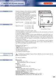
<strong>ATTUATORE</strong> <strong>DIMMER</strong><br />
<strong>RESISTIVO</strong> <strong>INDUTTIVO</strong> (<strong>600W</strong>)<br />
Articolo n.<br />
GW 90 758<br />
B<br />
L<br />
T<br />
+ -<br />
Bus<br />
Prog<br />
ON<br />
Colore<br />
grigio chiaro<br />
ATTENZIONE :<br />
In caso di disinserimento l’uscita, anche nella posizione disinserita di<br />
“OFF”, non è priva di tensione.<br />
Il LED rosso “OVL” indica il caso di sovraccarico. Nel caso si verifichi un<br />
sovraccarico, l’attuatore dimmer resta definitivamente spento. È possibile<br />
riavviare l’attuatore dimmer dopo la ricezione di un telegramma di OFF<br />
oppure dopo aver disinserito brevemente la tensione di rete.<br />
La protezione contro il corto circuito sull’uscita è garantita mediante un<br />
fusibile integrato (T2,5H).<br />
L’apparecchio è allestito con tre morsetti ad innesto avvitabili:<br />
- 1 morsetto per il conduttore di neutro<br />
- 1 morsetto per il conduttore esterno<br />
- 1 morsetti per il conduttore esterno attenuato<br />
La temperatura ambiente prescritta non deve essere superata. Se così non<br />
fosse, bisogna sempre provvedere ad una ventilazione adeguata.<br />
N L<br />
OFF ON<br />
BUS<br />
T2,5H<br />
EIB<br />
FUNZIONE<br />
L’attuatore dimmer GW 90 758 serve ad attenuare le lampade ad<br />
incandescenza e i carichi induttivi (lampade alogene tramite trasformatori<br />
con avvolgimento attenuabili) con una potenza massima di circa 600 Watt/<br />
VA (ritardo di fase).<br />
Con l’ausilio di un’applicazione particolare l’apparecchio può essere utilizzato<br />
per il controllo del numero di giri dei motori monofase a tensione alternata,<br />
come per esempio motori asincroni.<br />
MONTAGGIO<br />
L’attuatore dimmer GW 90 758 è un apparecchio per il montaggio su una<br />
guida DIN EN50022. Non è necessario un binario dati.<br />
Il collegamento al Bus avviene tramite il morsetto di collegamento al Bus<br />
compreso nella fornitura.<br />
Infine si infila il copricavo sopra il morsetto di connessione Bus al fine di<br />
garantire una distanza di sicurezza della linea Bus rispetto alle linee a 230V.<br />
Al massimo possono essere collegate 4 coppie di fili a un morsetto di<br />
collegamento al Bus.<br />
Le linee verso le utenze e la tensione di rete sono collegate mediante<br />
morsetti ad innesto avvitabili. I cavi possono essere avvitati ai morsetti ad<br />
innesto prima del montaggio dell’apparecchio ed innestati successivamente.<br />
I morsetti non devono essere inseriti quando sono sotto tensione.<br />
Tutti gli apparecchi che sono montati affianco all’attuatore dimmer devono<br />
essere allestiti almeno con un isolamento principale.<br />
Un LED giallo “OUT” indica se è presente la tensione alle utenze in caso di<br />
servizio Bus. Nel caso l’interruttore manuale non si trovi nella posizione<br />
“BUS” oppure dopo una caduta della tensione Bus, lo stato dell’apparecchio<br />
può discostarsi da quello del LED di stato giallo.<br />
Solo nel caso il programma applicativo sia stato caricato correttamente<br />
nell’apparecchio si accende il LED verde di servizio “RUN”. Tramite<br />
l’interruttore manuale è possibile selezionare le funzioni "Acceso, spento e<br />
servizio Bus".<br />
Nel caso di accensione “ON” tramite l’interruttore manuale, l’apparecchio<br />
provvede ad attenuare alla massima luminosità anche senza<br />
programmazione.<br />
M<br />
t ≤<br />
a 45˚C<br />
OVL OUT RUN<br />
25-600VA<br />
AC 230V 50Hz<br />
ATTENZIONE:<br />
Disinserire la tensione di rete prima di collegare l’apparecchio<br />
all’utenza.<br />
L’interruttore manuale non mette fuori tensione l’uscita dell’attuatore<br />
dimmer.<br />
È sempre latente all’uscita una tensione residua per la protezione<br />
contro i corti circuiti.<br />
GEWISS - MATERIALE ELETTRICO<br />
SAT<br />
DATI TECNICI<br />
Alimentazione dal Bus: DC 24 V / ca. 5 mA<br />
Tensione di isolamento: AC 4 kV Bus/tensione di rete<br />
Tensione nominale: 230 V AC, 50/-60 Hz<br />
Potenza nominale:<br />
- Lampade a incandescenza: 25-600 W<br />
- Lampade alogene: 25-600 W<br />
- Carico capacitivo 25-600 VA<br />
Fusibile<br />
- Cortocircuito fusibile (T2,5H)<br />
- Sovraccarico: protezione elettronica<br />
Temperatura ambiente<br />
- Funzionamento: -5 °C ÷ +45 °C<br />
- Immagazzinaggio: -25° C ÷ +55 °C<br />
- Trasporto: -25° C ÷ +70°C<br />
Umidità massima: 93 %<br />
Ambiente: l'apparecchio è progettato per essere impiegato fino a<br />
un'altitudine di 2000 m sul livello del mare (s.l.m.).<br />
Elemento di azionamento:<br />
- Tasto di programmazione<br />
- Interruttore manuale per "Acceso, spento e servizio Bus"<br />
Elemento di visualizzazione:<br />
- LED rosso per il controllo della tensione Bus e inserimento indirizzo fisico<br />
- LED verde applicazione in corso<br />
- LED giallo ad indicare lo stato di commutazione<br />
- LED rosso per controllo di programmazione<br />
Connessioni<br />
- Bus: tramite due pin da 1 mm per morsetto di collegamento al Bus<br />
- Conduttore di neutro: quattro morsetti a innesto a 1 viti per max. 2,5 mm 2<br />
- Fase: quattro morsetti a innesto a 1 viti per max. 2,5 mm 2<br />
- Fase: quattro morsetti a innesto a 1 viti per max. 2,5 mm 2<br />
Tipo di protezione IP 20<br />
Direttive CE: è conforme alla direttiva sulla bassa tensione 73/23/CEE e a<br />
quella sulla compatibilità elettromagnetica 89/336/EWG<br />
Dimensioni: 90 x 72 x 65 mm (largh.xalt.xprof.)<br />
Larghezza apparecchio: 4 TE = 72 mm<br />
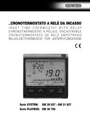
Esempio di collegamento:<br />
Bus<br />
+ -<br />
Accoppiatore Bus<br />
+39 035 946 111<br />
8.30 - 12.30 / 14.00 - 18.00<br />
da lunedì a venerdì<br />
L<br />
N<br />
+39 035 946 260<br />
24 ore al giorno<br />
L1 N<br />
SAT on line<br />
@ gewiss@gewiss.com<br />
Cod. 7.00.8.975.0
GB<br />
<strong>DIMMER</strong> ACTUATOR<br />
(OHMIC-INDUCTIVE LOADS) <strong>600W</strong><br />
Article no.<br />
GW 90 758<br />
B<br />
L<br />
T<br />
+ -<br />
Bus<br />
Prog<br />
ON<br />
Colour<br />
Iight grey<br />
WARNING:<br />
In the case of switching off, the output, even in the “OFF” position, is<br />
not powered down.<br />
The red “OVL” LED shows an overload. The dimmer will remain definitively<br />
off if an overload occurs. The dimmer can only be restarted after receipt of<br />
an OFF telegram or after having briefly cut off the mains voltage.<br />
The output is protected against short circuits by an integrated fuse (T2.5H).<br />
The device is provided with three screw coupling terminals:<br />
- 1 terminal for the neutral conductor<br />
- 1 terminal for the external conducttor<br />
- 1 terminal for the external dimming conductor<br />
The prescribed ambient temperature should never be exceeded. Adequate<br />
ventilation must always be provided if this is not the case.<br />
N L<br />
OFF ON<br />
BUS<br />
T2,5H<br />
EIB<br />
FUNCTION<br />
The GW 90 758 light dimming actuator (dimmer) is used to dim<br />
incandescent lights and inductive loads (halogen lights using transformers<br />
with a winding that can be attenuated) with a maximum power of about 600<br />
Watts/VA (phase delay).<br />
With the help of a special application the device can be used for controlling<br />
the number of revs of alternating current single phase motors such as, for<br />
example, asynchronous motors with split or universal poles.<br />
ASSEMBLY<br />
The GW 90 757 dimmer actuator is a device for connection on an EN50022<br />
DIN guide. A data rail is not required.<br />
The connection to the Bus is made using the Bus connection terminal<br />
included in the supply.<br />
Finally the cable cover is inserted above the Bus connection terminal to<br />
ensure a safety distance between the Bus line and the 230V line. A<br />
maximum of 4 pairs of wires can be connected to a Bus connection<br />
terminal.<br />
The lines to the services and to the mains voltage are connected using<br />
screwed coupling terminals.<br />
The cables can be screwed to the coupling terminals before assembly of the<br />
appliance and coupled subsequently. The terminals must not be inserted<br />
when they are under power.<br />
All devices installed next to the dimmer actuator must be provided with at<br />
least basic insulation.<br />
A yellow “OUT” LED shows whether the services are powered up in the case<br />
of a Bus service. If the manual switch is not in the “BUS” position or after a<br />
Bus voltage drop, the status of the device could be different to that of the<br />
yellow status LED.<br />
The green “RUN” service LED will only light up if the application program<br />
has been loaded into the device correctly. The manual switch can be used<br />
to select the “On, off and Bus service” functions. In the case of switching<br />
“ON” using the manual switch, the device will provide maximum<br />
brightness, even without programming.<br />
M<br />
t ≤<br />
a 45˚C<br />
OVL OUT RUN<br />
25-600VA<br />
AC 230V 50Hz<br />
TECHNICAL DATA<br />
Bus power supply: 24 V DC/ approx. 5 mA<br />
Insulation voltage: 4 kV AC Bus/mains voltage<br />
Rated voltage: 230 V AC, 50/-60 Hz<br />
Rated power:<br />
- Incandescent lamps: 25-600 W<br />
- Halogen lamps: 25-600 W<br />
- Capacitative load 25-600 VA<br />
Fuse<br />
- Short circuit fuse (T2.5H)<br />
- Overload: electronic protection<br />
Ambient temperature<br />
- Operation: -5 °C ÷ +45 °C<br />
- Storage: -25° C ÷ +55 °C<br />
- Transport: -25° C ÷ +70°C<br />
Max. humidity: 93 %<br />
Location: the device is designed to be used up to an altitude of 2000 m<br />
above sea level (a.s.l.).<br />
Actuation element:<br />
- Programming button<br />
- Manual switch for “On, off and Bus service”<br />
Display element:<br />
- Red LED for checking the Bus voltage and entry of the physical address<br />
- Green application running LED<br />
- Yellow LED showing the switching status<br />
- Red LED for checking programming<br />
Connections<br />
- Bus: using two 1-mm pins per Bus connection terminal<br />
- Neutral conductor: four 1-screw coupling terminals up to a max. of 2.5 mm 2<br />
- Phase: four 1-screw coupling terminals up to a max. of 2.5 mm 2<br />
- Phase: four 1-screw coupling terminals up to a max. of 2.5 mm 2<br />
Protection rating: IP 20<br />
EU Directives: it conforms to the low voltage Directive 73/23/EEC and the<br />
electromagnetic compatibility (EMC) Directive 89/336/EC<br />
Dimensions: 90 x 72 x 65 mm (heightxwidthxdepth)<br />
Appliance width: 4 TE = 72 mm<br />
Connection example:<br />
Bus<br />
+ -<br />
Bus coupler<br />
L<br />
N<br />
L1 N<br />
WARNING:<br />
Power down the mains voltage before connecting the appliance to<br />
the service.<br />
The manual switch does not power down the dimmer actuator<br />
output.<br />
Residual power is always latent at the output as protection against<br />
short circuits.<br />
GEWISS - MATERIALE ELETTRICO<br />
SAT<br />
+39 035 946 111<br />
8.30 - 12.30 / 14.00 - 18.00<br />
for monday to friday<br />
+39 035 946 260<br />
24 hours/day<br />
SAT on line<br />
@ gewiss@gewiss.com<br />
Cod. 7.00.8.975.0