ATTUATORE DIMMER RESISTIVO-INDUTTIVO 2x300W - Gewiss
ATTUATORE DIMMER RESISTIVO-INDUTTIVO 2x300W - Gewiss
ATTUATORE DIMMER RESISTIVO-INDUTTIVO 2x300W - Gewiss

Create successful ePaper yourself
Turn your PDF publications into a flip-book with our unique Google optimized e-Paper software.
<strong>ATTUATORE</strong> <strong>DIMMER</strong> <strong>RESISTIVO</strong>-<strong>INDUTTIVO</strong><br />
<strong>2x300W</strong><br />
Articolo n.<br />
GW 90 759<br />
I<br />
Colore<br />
grigio chiaro<br />
Il ripristino del canale dimmer può avvenire come segue:<br />
- mediante la ricezione di un telegramma off<br />
- mediante temporaneo scollegamento della tensione di rete<br />
- mediante un reset del bus (circa 20 secondi)<br />
Un corto circuito in uscita ha effetto su entrambi i canali, la protezione è<br />
assicurata tramite un fusibile integrato (T2,5H). L’apparecchio è dotato di 4<br />
morsetti ad innesto con viti:<br />
- 1 morsetto per il conduttore di Neutro<br />
- 1 morsetto per il conduttore di fase<br />
- 2 morsetti per le linee di carichi dimmerabili<br />
Non deve essere superata la temperatura ambiente prescritta.<br />
Cod. 7.01.0.350.2<br />
FUNzIONE<br />
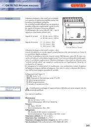
L’attuatore dimmer 2x300 W (art. GW 90 759) può regolare lampade ad<br />
incandescenza e carichi induttivi (lampade alogene con trasformatori ad<br />
avvolgimento dimmerabili) con una potenza massima di 300 Watt/VA per<br />
ogni canale (controllo di fase).<br />
MONTAGGIO<br />
PERICOLO DI MORTE:<br />
Tutte le operazioni sull’apparecchiatura devono essere eseguite da<br />
personale elettricista qualificato. Fare attenzione alle disposizioni<br />
nazionali specifiche nonché alle direttive EIB in vigore.<br />
PERICOLO DI MORTE:<br />
Le uscite possono essere sotto tensione anche con il dimmer spento.<br />
Durante i lavori sulle utenze collegate, togliere sempre la tensione<br />
tramite l’interruttore automatico a monte.<br />
ATTENzIONE<br />
Tutti gli apparecchi che sono montati a fianco dell’attuatore dimmer,<br />
devono essere provvisti almeno di un isolamento base!<br />
ATTENzIONE<br />
Durante il funzionamento, il dimmer necessita di un carico minimo di<br />
25 W/VA. In caso di carico inferiore possono verificarsi dei<br />
malfunzionamenti.<br />
DATI TECNICI<br />
Alimentazione dal bus: DC 24V / ca. 10 mA<br />
Tensione di isolamento: AC 4 kV bus/tensione di rete<br />
Tensione nominale: AC 230 V / 50 Hz<br />
Potenza nominale (per ogni canale)<br />
- Lampade incandescenti: 25-300 W<br />
- Lampade alogene HV: 25-300 W (HV=alta tensione)<br />
- Carichi induttivi: 25-300 VA<br />
Carico minimo (per ogni canale): 25 W/VA<br />
Protezione contro<br />
- cortocircuito: fusibile (T2.5H)<br />
- sovraccarico: (per ogni canale) protezione elettronica<br />
Temperatura ambiente<br />
- funzionamento: da -5 °C fino a +45 °C<br />
- stoccaggio: da -25 °C fino a +55 °C<br />
- trasporto: da -25 °C fino a +70 °C<br />
Umidità massima: 93 % di umidità relativa, nessuna formazione di condensa<br />
Ambiente:L’apparecchio è realizzato per l’impiego ad un’altezza massima di<br />
2000 m sul livello del mare (MSL).<br />
Elemento di comando: pulsante di programmazione<br />
Elemento di segnalazione: led rosso per il controllo della tensione bus e<br />
inserimento dell’indirizzo fisico<br />
led verde per segnalazione applicazione in corso e intermittente per la<br />
segnalazione di sovraccarico<br />
Collegamenti<br />
- Bus: tramite due pin da 1 mm per il morsetto di collegamento bus<br />
- Conduttore neutro: morsetti ad innesto con viti per massimo 2,5 mm 2<br />
- Conduttore di fase: morsetti ad innesto con viti per massimo 2,5 mm 2<br />
- Linee dei carichi dimmerabili: morsetti ad innesto con viti per<br />
massimo 2,5 mm 2<br />
Tipo di protezione: IP20<br />
Direttive UE: Corrisponde alla direttiva sulla la bassa tensione 73/23/CEE;<br />
corrisponde alla direttiva sulla compatibilità elettromagnetica 89/336/CEE<br />
Dimensioni: 90x108x65 mm (AxLxP)<br />
Larghezza apparecchio: 6 moduli EN 50022 = 108 mm<br />
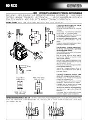
L’attuatore dimmer GW 90 759 è un’apparecchiatura modulare e viene<br />
montata su una guida ad istallazione rapida DIN-EN 50022. Un binario dati<br />
non è necessario.<br />
Il collegamento bus avviene tramite il morsetto di collegamento bus incluso<br />
nella fornitura. Successivamente viene inserito il copricavo sul morsetto di<br />
collegamento bus al fine di garantire la dovuta distanza di sicurezza tra la<br />
linea bus e la linea di alimentazione da 230V.<br />
Al morsetto di collegamento bus possono essere connesse al massimo 4<br />
coppie di fili. La linea verso l’utenza e la rete di alimentazione sono collegate<br />
tramite morsetti ad innesto con viti.<br />
I cavi possono essere prima avvitati sulla morsettiera dell’apparecchiatura e<br />
innestati successivamente. L’innesto del morsetto deve avvenire in assenza<br />
di tensione. Il led verde di servizio "RUN" si accende solamente quando il<br />
programma applicativo è stato caricato correttamente nell’apparecchio.<br />
Il led verde di servizio "RUN" indica tramite una regolare intermittenza (circa<br />
1 volta per secondo) un eventuale sovraccarico.<br />
In presenza di sovraccarico, il relativo canale dimmer viene spento in modo<br />
permanente.<br />
+39 035 946 111<br />
8.30 - 12.30 / 14.00 - 18.00<br />
lunedì ÷ venerdì - monday ÷ friday<br />
Esempio di collegamento:<br />
unità di accoppiamento bus<br />
Ai sensi dell’articolo 9 comma 2 della Direttiva Europea 2004/108/CE e dell’articolo R2 comma 6 della Decisione 768/2008/CE si informa che responsabile dell’immissione del prodotto sul mercato Comunitario è:<br />
According to article 9 paragraph 2 of the European Directive 2004/108/EC and to article R2 paragraph 6 of the Decision 768/2008/EC, the responsible for placing the apparatus on the Community market is:<br />
GEWISS S.p.A Via A. Volta, 1 - 24069 Cenate Sotto (BG) Italy Tel: +39 035 946 111 Fax: +39 035 945 270 E-mail: qualitymarks@gewiss.com<br />
24h<br />
+39 035 946 260<br />
sat@gewiss.com<br />
www.gewiss.com<br />
ULTIMA REVISIONE 02/2011
DIMMING ACTUATOR 2x300 W<br />
Article no.<br />
GW 90 759<br />
GB<br />
Colour<br />
Iight grey<br />
The dimmer channel can be restarted as follows:<br />
- By receiving an Off telegram<br />
- By briefly disconnecting the mains voltage<br />
- By a bus reset (approx. 20 seconds)<br />
A short circuit on the output will affect both channels and protection is<br />
provided via the integrated fuse (T2.5H).<br />
The device has four plug-in terminals with screw connection:<br />
- 1 terminal for neutral conductor<br />
- 1 terminal for outer conductor<br />
- 2 terminals for dimmed outer conductors<br />
The specified ambient temperature may not be exceeded.<br />
Cod. 7.01.0.350.2<br />
FUNCTION<br />
The dimming actuator 2x300 W (art. GW 90 759) dims incandescent<br />
lamps and inductive loads (LV halogen lamps via dimmable, wound<br />
transformers) with a maximum power of 300 W/VA per channel (phase<br />
control).<br />
INSTALLATION<br />
RISk OF FATAL INjURy:<br />
All work carried out on the unit may only be performed by skilled<br />
electricians. Observe the regulations valid in the country of use, as<br />
well as the valid EIB guidelines.<br />
RISk OF FATAL INjURy:<br />
The outputs may carry an electrical voltage even when the dimmer is<br />
switched off. Always disconnect the fuse in the incoming circuit from<br />
the supply before working on connected loads.<br />
CAUTION<br />
All devices that are installed next to the dimming actuator must at<br />
least be equipped with basic insulation.<br />
CAUTION<br />
The dimmer requires a minimum load of 25 W/ VA for operation. If<br />
this is not met, malfunctions may arise.<br />
The dimming actuator GW 90 759 is a DIN rail mounted device and is<br />
mounted on a DIN rail EN 50022.<br />
A data rail is not required. The bus connection is carried out via the bus<br />
connecting terminal supplied with the device.<br />
The cable cover is then placed over the bus connecting terminal to<br />
guarantee the safety clearance of the bus cable to the 230 V cables.<br />
A maximum of four core pairs can be connected to the bus connecting<br />
terminal.<br />
The cable to the load and the mains voltage are connected via plug-in<br />
terminals with a screw connection.<br />
The cables can be screwed onto the plugin terminal before installing the<br />
device and then inserted at a later date. The insertion of the terminal may<br />
not take place in the energised state.<br />
The green "RUN" operating LED only lights up if the application program has<br />
been loaded into the device correctly.<br />
In the event of an overload, the green "RUN" LED will indicate this by<br />
flashing at regular intervals (about once per second).<br />
If an overload occurs, the dimmer affected will be permanently switched off.<br />
+39 035 946 111<br />
8.30 - 12.30 / 14.00 - 18.00<br />
lunedì ÷ venerdì - monday ÷ friday<br />
TEChNICAL DATA<br />
Power supply from the bus: DC 24 V / approx. 10 mA<br />
Insulation voltage: AC 4 kV bus/mains voltage<br />
Nominal voltage: AC 230 V / 50 Hz<br />
Nominal power (per channel)<br />
- Incandescent lamps: 25-300 W<br />
- HV halogen lamps: 25-300 W<br />
- Inductive loads: 25-300 VA<br />
Minimum load (per channel): 25 W/VA<br />
Protection<br />
- Short circuit: Fuse (T2.5H)<br />
- Overload (per channel): Electronic fusing<br />
Ambient temperature<br />
- Operation: -5°C to +45°C<br />
- Storage: -25°C to +55°C<br />
- Transport: -25°C to +70°C<br />
Max. humidity: 93 % relative humidity, no moisture condensation<br />
Environment: The device is designed for use at a height of up to 2000 m<br />
above sea level (MSL).<br />
Operating elements: Programming button<br />
Display elements: Red LED for checking the bus voltage and for entering<br />
the physical address.<br />
Green LED for running application and flashing to indicate overload<br />
Connections<br />
- Bus: via two 1 mm pins for bus connecting terminal<br />
- Neutral conductor: 1-pole plug-in terminals with screw connection for<br />
max. 2.5 mm 2<br />
- Outer conductor: 1-pole plug-in terminals with screw connection for<br />
max. 2.5 mm 2<br />
- Dimmed outer conductor: 2-pole plug-in terminals with screw<br />
connection for max. 2.5 mm 2<br />
Type of protection: IP 20<br />
EC guidelines: Complies with low-voltage directive 73/23/EEC;<br />
Complies with EMC directive 89/336/EEC<br />
Dimensions: 90x108x65 mm (HxWxD)<br />
Device width: 6 modules = 108 mm<br />
Connection example<br />
Bus coupler<br />
Ai sensi dell’articolo 9 comma 2 della Direttiva Europea 2004/108/CE e dell’articolo R2 comma 6 della Decisione 768/2008/CE si informa che responsabile dell’immissione del prodotto sul mercato Comunitario è:<br />
According to article 9 paragraph 2 of the European Directive 2004/108/EC and to article R2 paragraph 6 of the Decision 768/2008/EC, the responsible for placing the apparatus on the Community market is:<br />
GEWISS S.p.A Via A. Volta, 1 - 24069 Cenate Sotto (BG) Italy Tel: +39 035 946 111 Fax: +39 035 945 270 E-mail: qualitymarks@gewiss.com<br />
24h<br />
+39 035 946 260<br />
sat@gewiss.com<br />
www.gewiss.com<br />
ULTIMA REVISIONE 02/2011