modulhard'andrea - Империя металлов
modulhard'andrea - Империя металлов
modulhard'andrea - Империя металлов

Create successful ePaper yourself
Turn your PDF publications into a flip-book with our unique Google optimized e-Paper software.
Operation and<br />
component<br />
Funktion und<br />
komponenten<br />
Funcionamiento y<br />
componentes<br />
Fonctionnement<br />
et composants<br />
Funzionamento e<br />
componenti<br />
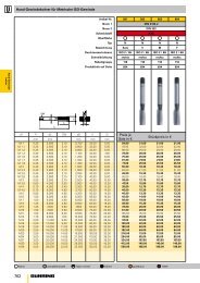
OPERATION<br />
ON the U-COMAC one<br />
turn of the “A” drive shaft<br />
corresponds to a 1 mm<br />
radial movement of the<br />
slide. The maximum number<br />
of 1000 rpm allowed by the<br />
“A” drive corresponds to a<br />
slide feed speed of<br />
1000 mm/min.<br />
Between the servomotor<br />
on the U-DRIVE unit and<br />
the toolholder slide of<br />
the U-COMAX is a radial<br />
clearance to the reversal<br />
process of about 0.05 mm,<br />
therefore the positioning, to<br />
be precise, must take place<br />
in a one-way direction and<br />
must be prepared during the<br />
programming phase.<br />
COMPONENTS<br />
1. Adapter flange to the<br />
machine (see pag 64)<br />
2. Rotating body<br />
3. Toolholder slide<br />
4. “A” drive shaft<br />
FUNKTION<br />
Auf U-COMAX entspricht<br />
eine Umdrehung der<br />
Antriebswelle “A” einem<br />
Radialverschub des Schlittens<br />
von 1mm. Die maximale<br />
zugelassene Umdrehungszahl<br />
von 1000 Umd/Min der<br />
Antriebswelle “A” entspricht<br />
einer Vorschubgeschwindigkeit<br />
des Schlittens von 1000 mm/Min.<br />
Zwischen dem in der<br />
U-DRIVE Gruppe montierten<br />
Servomotor und dem U-COMAX<br />
Werkzeughalteschlitten besteht<br />
ein Umsteuerungsradialspiel<br />
von ca. 0,05 mm, dadurch muss<br />
die Positionierung zu deren<br />
Präzision nur in einer Richtung<br />
und in Programmierungsphase<br />
erfolgen.<br />
KOMPONENTEN<br />
1. Anpassungsflansch der<br />
Maschine (siehe Seite 64)<br />
2. Drehkörper<br />
3. Werkzeughalteschlitten<br />
4. Antriebswelle ‘A’<br />
FUNCIONAMIENTO<br />
En los U-COMAX una<br />
revolución del eje de<br />
transmisión “A” corresponde a<br />
un desplazamiento radial de la<br />
corredera de 1 mm.<br />
El número máximo de 1000<br />
rev./min. admitido para el eje<br />
de transmisión “A” corresponde<br />
a una velocidad de avance<br />
corredera de 1000 mm/min.<br />
Entre el servomotor montado<br />
en el grupo U-DRIVE y la<br />
corredera portaherramienta del<br />
U-COMAX existe un juego radial<br />
a la inversión de unos 0,05 mm,<br />
por lo tanto el posicionamiento,<br />
para ser preciso, ha de ocurrir<br />
en sentido unidireccional y<br />
ha de ser previsto en fase de<br />
programación.<br />
FONCTIONNEMENT<br />
Sur les U-COMAX, un tour de<br />
l’arbre de transmission « A »<br />
correspond à un déplacement<br />
radial du coulisseau de 1 mm.<br />
Le nombre maximum de 1000<br />
tours/min. admis sur l’arbre de<br />
transmission « A » correspond<br />
à une vitesse d’avance du<br />
coulisseau de 1000 mm/min.<br />
Entre le servo-moteur monté<br />
sur le groupe U-DRIVE et le<br />
coulisseau porte-outils de la<br />
U-COMAX, il existe un jeu<br />
radial à l’inversion de 0,05<br />
mm environ. Par conséquent,<br />
le positionnement, pour être<br />
précis, doit se produire dans<br />
un sens unidirectionnel et<br />
doit être prévu en phase de<br />
programmation.<br />
FUNZIONAMENTO<br />
Sulle U-COMAX un giro<br />
dell’albero di trasmissione “A”<br />
corrisponde ad uno<br />
spostamento radiale della slitta<br />
di 1 mm. Il massimo numero<br />
di 1000 giri/min. ammesso<br />
all’albero di trasmissione “A”<br />
corrisponde ad una velocità di<br />
avanzamento slitta di<br />
1000 mm/min.<br />
Tra il servomotore montato<br />
nel gruppo U-DRIVE e la slitta<br />
portautensile della U-COMAX<br />
esiste un gioco radiale<br />
all’inversione di circa 0,05 mm,<br />
per cui il posizionamento, per<br />
essere preciso, deve avvenire<br />
in senso unidirezionale e deve<br />
essere previsto in fase di<br />
programmazione.<br />
COMPONENTES<br />
1. Estribo de adaptación a la<br />
máquina (véase pág 64)<br />
2. Cuerpo giratorio<br />
3. Corredera portaherramientas<br />
4. Eje de transmisión ‘A’<br />
COMPOSANTS<br />
1. Bride d’adaptation à la<br />
machine (cf. page 64)<br />
2. Corps rotatif<br />
3. Coulisseau porte-outils<br />
4. Arbre de transmission « A »<br />
COMPONENTI<br />
1. Flangia di adattamento alla<br />
macchina (vedere pag 64)<br />
2. Corpo rotante<br />
3. Slitta portautensili<br />
4. Albero di trasmissione ‘A’<br />
4<br />
A<br />
2<br />
1<br />
3<br />
331<br />
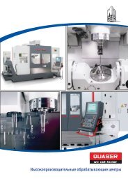
U-Drive<br />
U-Drive U-Drive U-Drive U-Drive<br />
The U-Drive drive unit<br />
for U-Comax heads is<br />
mounted behind the<br />
spindle of the machine. It<br />
is controlled by an axle of<br />
the numeric control and<br />
mechanically connected to<br />
the U-Comax head drive<br />
with a transmission shaft<br />
that crosses the spindle of<br />
the machine.<br />
The U-Drive drive unit can<br />
be configured in various<br />
ways depending on the<br />
required application and the<br />
design of the machine.<br />
Die U-Drive Motorisierung<br />
der U-Comax Köpfe wird<br />
hinter der Maschinenspindel<br />
montiert, von einer Achse<br />
der numerischen Steuerung<br />
verwaltet und mechanisch an<br />
den Bewegungsanschluss der<br />
U-Comax Köpfe durch eine<br />
Antriebswelle angeschlossen,<br />
welche die Spindel der<br />
Maschine selbst durchquert.<br />
Die U-Drive Motorisierung<br />
kann je nach Anbringung<br />
und Herstellungsform der<br />
Maschine, verschieden<br />
gestaltet werden.<br />
La motorización U-Drive para<br />
los cabezales U-Comax se<br />
monta en la parte trasera<br />
con respecto al mandril de<br />
la máquina, es mandado por<br />
un eje del control numérico y<br />
conectada mecánicamente a<br />
la toma de movimiento de los<br />
cabezales U-Comax con un eje<br />
de transmisión que atraviesa el<br />
mandril de la máquina misma.<br />
La motorización U-Drive<br />
puede tener diferentes<br />
configuraciones según<br />
la aplicación y la forma<br />
constructiva de la máquina.<br />
Le système moteur U-Drive<br />
pour les têtes U-Comax est<br />
monté à l’arrière par rapport<br />
à la broche de la machine.<br />
Il est géré par un axe de la<br />
commande numérique et est<br />
relié mécaniquement à la<br />
prise de mouvement des têtes<br />
U-Comax par un arbre de<br />
transmission qui traverse la<br />
broche de la machine.<br />
Le système moteur U-Drive<br />
peut avoir différentes<br />
configurations selon<br />
l’application et la forme de<br />
construction de la machine.<br />
La motorizzazione U-Drive<br />
per le teste U-Comax viene<br />
montata posteriormente al<br />
mandrino della macchina,<br />
viene gestito da un asse del<br />
controllo numerico e collegata<br />
meccanicamente alla presa di<br />
moto della teste U-Comax con<br />
un albero di trasmissione che<br />
attraversa il mandrino della<br />
macchina stessa.<br />
La motorizzazione U-Drive<br />
può assumere diverse<br />
configurazioni a seconda<br />
dell’applicazione e della forma<br />
costruttiva della macchina.<br />
U-DRIVE<br />
U-CX