modulhard'andrea - Империя металлов
modulhard'andrea - Империя металлов
modulhard'andrea - Империя металлов

Create successful ePaper yourself
Turn your PDF publications into a flip-book with our unique Google optimized e-Paper software.
Prearrangements<br />
Voreinstellungen Predisposiciones Prédispositions Predisposizioni<br />
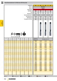
COOLANT<br />
SUPPLY fig.1-2<br />
Internal grooves are<br />
provided inside the<br />
U-TRONIC head that allow<br />
coolants to pass through<br />
from the machine spindle<br />
until the two threaded holes<br />
located next to the slide.<br />
Hoses can be screwed on<br />
these holes to bring coolant<br />
directly to the tool.<br />
A - INTERNAL<br />
PRESSURIZATION fig.1<br />
To prevent liquid and dust<br />
from getting into the motor,<br />
transducer, and limit switch<br />
areas, an Ø 8,5 (A) hole<br />
is provided for internal<br />
pressurization of the fixed<br />
body with and air inlet at<br />
0.5-1 BAR.<br />
ZUFÜHRUNG DES<br />
KÜHLMITTELS fig.1-2<br />
Im Inneren des U-TRONIC<br />
Drehkörpers sind Kanäle<br />
für den Durchfluss des<br />
Kühlmittels von der Spindel<br />
zur Maschine und bis zu zwei<br />
Gewindebohrungen seitlich<br />
des Schlittens vorgesehen.<br />
An den Seiten der Bohrungen<br />
können flexible Leitungen<br />
angeschraubt werden, um<br />
das Kühlmittel direkt zum<br />
Werkzeug zu leiten.<br />
A- INTERNER<br />
DRUCKAUSGLEICH fig.1<br />
Um zu vermeiden, dass<br />
Flüssigkeit und Staub in<br />
den Bereich des Motors,<br />
des Wandlers und des<br />
Begrenzungsschalters<br />
eintreten, ist eine Bohrung<br />
Ø 8,5 (A) zum Ausgleich des<br />
Drucks im Inneren des festen<br />
Körpers mit Luftzufuhr zu<br />
0,5-1 BAR vorgesehen.<br />
ABASTECIMIENTO LÍQUIDO<br />
REFRIGERANTE fig.1-2<br />
En el interior del cuerpo<br />
giratorio del U-TRONIC<br />
están previstas unas<br />
canalizaciones que<br />
permiten el paso del líquido<br />
refrigerante por el husillo<br />
de la máquina hasta dos<br />
agujeros roscados situados al<br />
lado de la corredera.<br />
En dichos agujeros es posible<br />
enroscar unos conductos<br />
flexibles y llevar el líquido<br />
refrigerante directamente a la<br />
herramienta.<br />
A- PRESURIZACIÓN<br />
INTERNA fig.1<br />
Para evitar que líquido y<br />
polvo entren en la zona del<br />
motor, transductor y final<br />
de carrera, está previsto<br />
un agujero Ø 8,5 (A) para<br />
presurizar el interior del<br />
cuerpo fijo con la entrada<br />
del aire a 0,5-1 BAR.<br />
AMENÉE DE LIQUIDE<br />
RÉFRIGÉRANT fig.1-2<br />
Des canalisations sont<br />
prévues à l’intérieur du corps<br />
rotatif de la U-TRONIC,<br />
qui permettent le passage<br />
du liquide réfrigérant de<br />
la broche de la machine<br />
jusqu’aux deux orifices<br />
taraudés placés sur les<br />
côtés du coulisseau. Il est<br />
possible de visser sur ces<br />
orifices des tuyaux flexibles<br />
et de transporter le liquide<br />
réfrigérant directement dans<br />
l’outil.<br />
A- PRESSURISATION<br />
INTERNE fig.1<br />
Afin d’éviter que les liquides<br />
et la poussière n’entrent dans<br />
la zone moteur, transducteur<br />
et fin de course, un orifice<br />
d’un diamètre de 8,5 mm (A)<br />
est prévu pour pressuriser<br />
l’intérieur du corps fixe avec<br />
une entrée d’air à 0,5-1 BAR.<br />
ADDUZIONE LIQUIDO<br />
REFRIGERANTE fig.1-2<br />
All’interno del corpo<br />
rotante della U-TRONIC<br />
sono previste delle<br />
canalizzazioni che<br />
permettono il passaggio<br />
del liquido refrigerante dal<br />
mandrino della macchina<br />
sino a due fori filettati posti<br />
a fianco della slitta. Su tali<br />
fori è possibile avvitare dei<br />
condotti flessibili e portare<br />
il liquido refrigerante ad<br />
direttamente all’utensile.<br />
A- PRESSURIZZAZIONE<br />
INTERNA fig.1<br />
Per evitare che liquido e<br />
polvere entrino nella zona<br />
del motore, trasduttore e<br />
finecorsa, è previsto un foro<br />
Ø 8,5 (A) per pressurizzare<br />
l'interno del corpo fisso con<br />
l'ingresso dell'aria a<br />
0,5-1 BAR.<br />
fig.1<br />
2<br />
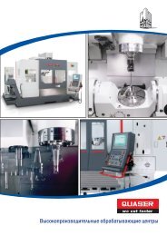
fig.2<br />
fig.3<br />
B<br />
315<br />
C<br />
A<br />
1<br />
B - AUTOMATIC<br />
GREASER fig.1<br />
A Ø 8,5 (B) hole is provided<br />
on the head so that grease<br />
can be automatically put in<br />
the U-TRONIC.<br />
C - ATOMIZED<br />
LUBRICATION fig.1<br />
To automatically lubricate<br />
the movement guides<br />
and the mother screw for<br />
dragging the toolholder<br />
slide located in the rotating<br />
body of the U-TRONIC, the<br />
head can be arranged, on<br />
request, for the introduction<br />
of a constant minimum flow<br />
of 10g/h of atomized oil at a<br />
pressure of 0,5 BAR in the<br />
Ø 8,5 (C) hole.<br />
BALANCING fig.3<br />
To improve working<br />
conditions and balance the<br />
position of the tool when it<br />
appears shifted in relation<br />
to the U-TRONIC axis,<br />
counterweights (1) can be<br />
applied using the threaded<br />
holes (2) located on the<br />
rotating body.<br />
B - AUTOMATISCHE<br />
SCHMIERVORRICHTUNG fig.1<br />
Auf dem Kopf befindet sich<br />
eine Bohrung Ø 8,5 (B) zum<br />
automatischen Einführen<br />
des Fettes ins Innere von<br />
U-TRONIC.<br />
C - ZERSTÄUBTE<br />
SCHMIERUNG fig.1<br />
Zum automatischen<br />
Schmieren der sich im<br />
Drehkörper von U-TRONIC<br />
befindenden Gleitschienen<br />
und der Hauptspindel<br />
für das Gleiten des<br />
Werkzeughalteschlittens,<br />
kann der Kopf auf Anfrage so<br />
ausgestattet werden, dass<br />
durch die Öse Ø 8,5 (C) ein<br />
konstanter Mindestflusses<br />
von 10g/h zerstäubten Öls mit<br />
einem Druck zu 0,5-1 BAR<br />
eingeführt werden kann.<br />
AUSGLEICH fig.3<br />
Zum Verbessern der<br />
Arbeitsbedingungen und<br />
zum Ausgleich der eventuell<br />
gegenüber der U-TRONIC<br />
Achse verschobenen<br />
Werkzeugposition, können<br />
Gegengewichte (1) mittels<br />
Gewindebohrungen (2) auf<br />
dem Drehkörper, angebracht<br />
werden.<br />
B - ENGRASADOR<br />
AUTOMÁTICO fig.1<br />
En el cabezal está previsto<br />
un agujero Ø 8,5 (B) para<br />
permitir la introducción<br />
automática de la grasa en<br />
el interior del U-TRONIC.<br />
C - LUBRIFICACIÓN<br />
VAPORIZADA fig.1<br />
Para lubrificar<br />
automáticamente las guías<br />
de deslizamiento y el vis<br />
sin fin para el arrastre de la<br />
corredera portaherramienta<br />
situados en el cuerpo<br />
giratorio del U-TRONIC,<br />
bajo pedido predisponer el<br />
cabezal para introducir en<br />
el agujero Ø 8,5 (C) un flujo<br />
constante mínimo de 10g/h<br />
de aceite vaporizado a una<br />
presión 0,5-1 BAR.<br />
EQUILBRADO fig.3<br />
Para mejorar las condiciones<br />
de trabajo y equilibrar la<br />
posición de la herramienta<br />
cuando resulte desplazada<br />
con respecto al eje del<br />
U-TRONIC, es posible<br />
aplicar unos contrapesos<br />
(1) utilizando los agujeros<br />
roscados (2) situados en el<br />
cuerpo giratorio.<br />
B - GRAISSEUR<br />
AUTOMATIQUE fig.1<br />
La tête présente un orifice<br />
d’un diamètre de 8,5 mm<br />
(B) pour permettre l’insertion<br />
automatique de la graisse<br />
dans la U-TRONIC.<br />
C - LUBRIFICATION<br />
NÉBULISÉE fig.1<br />
Pour lubrifier<br />
automatiquement les<br />
glissières de coulissement<br />
et la vis mère d’entraînement<br />
du coulisseau porte-outils<br />
placées dans le corps<br />
rotatif de la U-TRONIC, sur<br />
demande il est possible<br />
predisposer la tête pour<br />
verser dans l’orifice d’ un<br />
diamétre de 8,5 mm (C), un<br />
débit constant minimum de<br />
10g/h d’huile nébulisée à<br />
une pression de 0,5-1 BAR.<br />
ÉQUILIBRAGE fig.3<br />
Pour améliorer les conditions<br />
d’usinage et équilibrer la<br />
position de l’outil, quand il<br />
est déplacé par rapport à<br />
l’axe de la U-TRONIC, il est<br />
possible d’appliquer des<br />
contre-poids (1) en utilisant<br />
les orifices taraudés (2)<br />
placés sur le corps rotatif.<br />
B - INGRASSATORE<br />
AUTOMATICO fig.1<br />
Sulla testa è previsto<br />
un foro Ø 8,5 (B) per<br />
permettere l’inserimento<br />
automatico del grasso<br />
all’interno della U-TRONIC.<br />
C - LUBRIFICAZIONE<br />
NEBULIZZATA fig.1<br />
Per lubrificare<br />
automaticamente le guide<br />
di scorrimento e la vite<br />
madre per il trascinamento<br />
della slitta portautensilie<br />
posti nel corpo rotante della<br />
U-TRONIC, a richiesta è<br />
possibile predisporre la<br />
testa per immetere nel<br />
foro Ø 8,5 (C) un flusso<br />
costante minimo di 10 g/h<br />
d’olio nebulizzato ad una<br />
pressione di 0,5-1 BAR.<br />
BILANCIATURA fig.3<br />
Per migliorare le condizioni<br />
di lavoro e bilanciare la<br />
posizione dell'utensile<br />
quando risulta spostato<br />
rispetto all'asse della<br />
U-TRONIC, é possibile<br />
applicare dei contrappesi (1)<br />
utilizzando i fori filettati (2)<br />
posti sul corpo rotante.