modulhard'andrea - Империя металлов
modulhard'andrea - Империя металлов
modulhard'andrea - Империя металлов

Create successful ePaper yourself
Turn your PDF publications into a flip-book with our unique Google optimized e-Paper software.
TA-TRONIC<br />
Application<br />
Anbringung Aplicaciones Application Applicazioni<br />
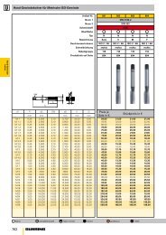
302<br />
CAUTION : One turn of the<br />
motor on the TA-TRONIC<br />
corresponds to a 0.5 mm.<br />
radial movement of the slide.<br />
The maximum number of<br />
1000 rpm allowed corresponds<br />
to a slide feed speed of<br />
500 mm/min. The required<br />
torque of the motor must be<br />
0,8~1 Nm. Between the motor<br />
in the and the toolholder slide<br />
there is a radical clearance<br />
to the reversal process of<br />
about 0.05 mm, therefore the<br />
positioning, to be precise,<br />
must take place in a one-way<br />
direction and must be prepared<br />
during the programming phase.<br />
TA-TRONIC is mounted on the<br />
machine using a taper (4)<br />
The anit-rotation pin (8)<br />
inserted in the dowel (10)<br />
locked on the head of the<br />
machine tool, preventing the<br />
fixed body of TA-TRONIC to<br />
rotate.<br />
The dowel (10) is applied on a<br />
fixed part around the spindle<br />
in relation to the dimensions<br />
of fig. 1, adjusting the height<br />
indicated by way of a<br />
thickness S.<br />
For heavy machining it is<br />
advisable to apply a flange<br />
(11) to make the TA-TRONIC<br />
solidly connected with the head<br />
of the machine tool (fig. 2-3).<br />
It is always advisable to use a<br />
flange with TA-TRONIC<br />
160 and 200.<br />
The type of flange to use<br />
depends on the model of the<br />
machine and may be easily<br />
built by the Customer or<br />
supplied by D'Andrea.<br />
ACHTUNG : bei TA_TRONIC<br />
entspricht eine Motorumdrehung<br />
einer Radialverschiebung des<br />
Schlittens von 0,5mm. Die höchste<br />
zugelassene Umdrehungszahl von<br />
1000 Umd/min, entspricht einer<br />
Vorschubsgeschwindigkeit des<br />
Schlittens von 500 mm / Min.<br />
Das nötige Motordrehmoment<br />
muss 0,8~1 Nm betragen.<br />
Zwischen Motor und<br />
Werkzeughalteschlitten besteht<br />
ein Umsteuerungsradialspiel<br />
von ungefähr 0,05 mm, daher<br />
muss die Positionierung, um<br />
präzise zu sein, einseitig gerichtet<br />
und in Programmierungsphase<br />
vorgenommen werden.<br />
Die TA TRONIC Vorrichtungen<br />
werden mittels Konus (4) an die<br />
Maschine angeschlossen.<br />
Der Rotationsverhindernde Bolzen<br />
(8), welcher in den, auf dem Kopf<br />
der Werkzeugmaschine befestigten<br />
Dübel (10) eingeführt ist, verhindert<br />
die Rotation des festen TA-TRONIC<br />
Körpers. Der Dübel (10) wird auf<br />
einen festen Teil rund um die<br />
Spindel, unter Berücksichtigung der<br />
Quoten von fig.1 und Einstellung<br />
der angegebenen Höhe mittels einer<br />
Distanzscheibe S, angebracht.<br />
Für schwerwiegende Arbeiten<br />
empfiehlt man das Anbringen eines<br />
Flansches (11) zum konsolidieren des<br />
TA TRONIC Kopfes mit dem Kopf der<br />
Werkzeugmaschine (fig. 2-3).<br />
Mit den TA TRONIC Vorrichtungen<br />
160 und 200 ist die Anwendung eines<br />
Flansches immer empfehlenswert.<br />
Die Art des zu verwendenden<br />
Flansches hängt vom<br />
Maschinenmodell ab und kann<br />
einfach vom Kunden selbst<br />
hergestellt, oder von D’Andrea<br />
geliefert werden.<br />
ATENCIÓN : En los TA-TRONIC<br />
una revolución de motor<br />
corresponde a un desplazamiento<br />
radial de la corredera de 0,5 mm.<br />
El número máximo de 1000 rev./<br />
min. admitido corresponde a una<br />
velocidad de avance corredera de<br />
500 mm/min. El par necesario del<br />
motor tiene que ser 0,8~1 Nm.<br />
Entre el motor y la corredera<br />
portaherramienta existe un<br />
juego radial a la inversión de<br />
aproximadamente 0,05 mm, es<br />
decir el posicionamiento, para<br />
ser preciso, tiene que ocurrir<br />
en sentido unidireccional y ha<br />
de estar previsto en fase de<br />
programación.<br />
Los TA-TRONIC se montan<br />
en la máquina mediante el<br />
cono (4).<br />
El perno antirotación (8),<br />
introducido en el macho (10)<br />
bloqueado en el cabezal de la<br />
máquina herramienta, impide<br />
la rotación del cuerpo fijo de la<br />
TA-TRONIC.<br />
El macho (10) ha de aplicarse<br />
en una parte fija alrededor del<br />
mandril respetando las cotas<br />
de fig.1, regulando la altura<br />
indicada por medio de un<br />
grosor S.<br />
Para elaboraciones pesadas<br />
se aconseja aplicar una brida<br />
(11) para volver solidario el<br />
TA-TRONIC con el cabezal de<br />
la máquina herramienta<br />
(fig. 2-3). Con los TA-TRONIC<br />
160 y 200 se aconseja siempre<br />
el uso de la brida.<br />
El tipo de brida por adoptar<br />
depende del modelo de la<br />
máquina y puede ser fácilmente<br />
construida por el Cliente o<br />
suministrada por D’Andrea.<br />
ATTENTION : Sur les<br />
TA-TRONIC, un tour de moteur<br />
correspond à un déplacement<br />
radial du coulisseau de 0,5 mm.<br />
Le nombre maximum de 1000<br />
tours/min. admis correspond<br />
à une vitesse d’avance du<br />
coulisseau de 500 mm/min.<br />
Le couple nécessaire du moteur<br />
doit être 0,8~1 Nm.Entre le<br />
moteur et le coulisseau porteoutil,<br />
il existe un jeu radial à<br />
l’inversion de 0,05 mm environ,<br />
donc le positionnement, pour<br />
être précis, doit se produire<br />
dans un sens unidirectionnel<br />
et doit être prévu en phase de<br />
programmation.<br />
Les TA-TRONIC sont montées<br />
sur la machine à l’aide du<br />
cône (4). Le pivot anti-rotation<br />
(8) inséré dans le tasseau<br />
(10) bloqué sur la tête de la<br />
machine outil, empêche la<br />
rotation du corps fixe de la<br />
TA-TRONIC.<br />
Le tasseau (10) doit être monté<br />
sur une partie fixe autour de la<br />
broche, en respectant les cotes<br />
de la figure 1, et en réglant la<br />
hauteur indiquée à l’aide de<br />
l’épaisseur S.<br />
Pour des usinages lourds,<br />
nous conseillons de monter<br />
une bride (11) pour relier la<br />
TA-TRONIC à la tête de la<br />
machine outil (figure 2-3).<br />
Avec les TA-TRONIC 160<br />
et 200, nous conseillons de<br />
toujours utiliser la bride.<br />
Le type de bride à utiliser<br />
dépend du modèle de la<br />
machine et peut être facilement<br />
fabriqué par le client ou fourni<br />
par D’Andrea.<br />
ATTENZIONE : Sulle<br />
TA-TRONIC un giro di motore<br />
corrisponde ad uno spostamento<br />
radiale della slitta di 0,5 mm. Il<br />
massimo numero di 1000 giri/<br />
min. ammesso corrisponde ad<br />
una velocità di avanzamento<br />
slitta di 500 mm/min. La coppia<br />
necessaria del motore deve<br />
essere 0,8~1 Nm.Tra il motore<br />
e la slitta portautensile esiste<br />
un gioco radiale all’inversione<br />
di circa 0,05 mm, per cui il<br />
posizionamento, per essere<br />
preciso, deve avvenire in<br />
senso unidirezionale e deve<br />
essere previsto in fase di<br />
programmazione.<br />
Le TA-TRONIC vengono<br />
montate sulla macchina<br />
mediante il cono (4).<br />
Il perno antirotazione (8),<br />
inserito nel tassello (10)<br />
bloccato sulla testa della<br />
macchina utensile, impedisce<br />
la rotazione del corpo fisso<br />
della TA-TRONIC.<br />
Il tassello (10) va applicato<br />
su una parte fissa attorno al<br />
mandrino rispettando le quote<br />
di fig.1, regolando l’altezza<br />
indicata per mezzo di uno<br />
spessore S.<br />
Per lavorazioni gravose è<br />
consigliabile applicare una<br />
flangia (11) per rendere<br />
solidale la TA-TRONIC con la<br />
testa della macchina utensile<br />
(fig. 2-3). Con le TA-TRONIC<br />
160 e 200 è sempre<br />
consigliato l’uso della flangia.<br />
Il tipo di flangia da adottare<br />
dipende dal modello della<br />
macchina e può essere<br />
facilmente costruita dal Cliente<br />
o fornita da D’Andrea.<br />
10<br />
18 + 0.03<br />
0<br />
20 S<br />
10<br />
33 ± 0.05<br />
26 ± 0.05 0.5 ~ 1<br />
37<br />
<br />
p.<br />
L<br />
4<br />
S<br />
8<br />
18 - 0.02<br />
- 0.04<br />
TA-T 100-125<br />
TA-T 160-200<br />
1<br />
TA-T 100-125<br />
TA-T 160-200<br />
I= 60<br />
I= 90<br />
fig.1