MINI Nike 24 3 E - Immergas
MINI Nike 24 3 E - Immergas MINI Nike 24 3 E - Immergas
ES PL TR CZ SI HU RU RO IE SK UA 154 3.4 INFORMATION MENU. Pressing the buttons (3 and 4) for 5 seconds, the “Information menu” is activated, which allows to display some boiler functioning parameters. To scroll through the various parameters, press (3 and 4), to exit from the menu press buttons (3 and 4) again for 5 seconds or press button (2) for 5 seconds or wait for 60 seconds. List of parameters. N° Description parameter d1 Displays the flame signal (uA). Displays the primary exchanger d2 output instant heating flow temperature. Displays the instant output d3 temperature from the DHW exchanger. Displays the temperature set for d4 the central heating set (if remote control is present). Displays the temperature set for d5 the DHW set (if remote control is present). Displays the external environment temperature (if the exter- d6 nal probe is present). If the temperature is below zero, the value is displayed flashing. 3.5 PROGRAMMING THE P.C.B. The boiler is prepared for possible programming of several operation parameters. By modifying these parameters as described below, the boiler can be adapted according to specific needs. To access the programming phase, proceed as follows: - press buttons (1) and (2) at the same time for approximately 8 seconds; - Using buttons (3) and (4), select the parameter to be changed indicated in the following table: List of parameters Description P1 Boiler mode (DO NOT USE) P2 Display lighting P3 DHW thermostat P4 Minimum CH output P5 Maximum CH output P6 Central heating ignitions timer P7 Central heating ramp timer P8 Heating switch-on delay request from room thermostat and remote control P9 Solar mode - adjust the corresponding value consulting the table using buttons (5) and (6); - confirm the set value pressing the Reset button (1) for approximately 3 seconds; by pressing keys (3) and (4) at the same time exit the function without memorising the modifications made. N.B.: after a period of time, without touching any keys, the operation cancels automatically. Boiler mode. It establishes whether the boiler functions in instant or storage mode. Boiler mode (P1) Range of values which can be set 0 - instant boiler 1 - boiler with storage tank Standard setting Illuminazione display. Stabilisce la modalità di illuminazione del display. Display lighting (P2) Range of values which can be set 0 - Off 1 - Auto 2 - On 0 Standard setting - Off: the display is always lit with low intensity. - Auto: the display lights up during use and lowers after 15 seconds of inactivity. In the case of anomaly the display flashes. - On: the display is always lit with high intensity. DHW thermostat. With the “correlated” thermostat setting, boiler switch-off takes place on the basis of the temperature set. While with the setting of the “fixed” DHW thermostat the switch-off temperature is fixed at the maximum value independently from the value set on the control panel. DHW thermostat (P3) Range of values which can be set 0 - Fixed 1 – Correlated 1 Standard setting 1 Heating output. The boiler also has electronic modulation that adapts the boiler potentiality to the effective heating demand of the house. Then the boiler works normally in a variable gas pressure field between the minimum heating power and the maximum heating power depending on the system’s heating load. N.B.: the boiler is produced and calibrated in the central heating phase at nominal output. Approximately 10 minutes are needed to reach the nominal heat output, which can be changed using the parameter (P5). N.B.: the selection of the “Minimum heating power” and “Maximum heating power” parameters, in the presence of a heating request, allows switch-on of the boiler and power supply of the modulator with current equal to the value of the respective set value. Minimum central heating output (P4) Range of values which can be set 0 - 63 % Maximum heating output (P5) Range of values which can be set Standard setting Set according to factory inspection Standard setting 0 - 99 % 99 Central heating ignitions timer. The boiler has electronic timing, which prevents the burner from igniting too often in central heating mode. Central heating ignitions timer (P6) Range of values which can be set 0 - 20 (0 - 10 minutes) (01 equals 30 seconds) Standard setting 6 (3’) Central heating ramp timing. In the ignition phase, the boiler performs an ignition ramp in order to arrive at the maximum power set. Central heating ramp timer (P7) Range of values which can be set 0 - 28 (0 - 14 minutes) (01 equals 30 seconds) Parameter 28 (14’)
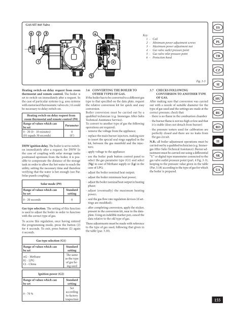
GAS SIT 845 Valve Heating switch-on delay request from room thermostat and remote control. The boiler is set to switch-on immediately after a request. In the case of particular systems (e.g. area systems with motorised thermostatic valves etc.) it could be necessary to delay switch-on. Heating switch-on delay request from room thermostat and remote control (P8) Range of values which can Parameter be set 0 - 20 (0 - 10 minutes) (01 equals 30 seconds) 0 (0’) DHW ignition delay. The boiler is set to switchon immediately after a request. for DHW In the case of coupling with solar storage tanks positioned upstream from the boiler, it is possible to compensate the distance of the storage tank in order to allow the hot water to reach the utility, setting the necessary time and therefore verifying that the water is hot enough (see Par. Solar panels coupling). Solar mode (P9) Range of values which can be set Standard setting 0 - 20 seconds 0 Gas type selection. The setting of this function is used to adjust the boiler in order to function with the correct type of gas. To access this regulation, once having entered the programming mode, press the button (2) for 4 seconds. To exit, press button (2) again 4 seconds. Gas type selection (G1) Range of values which can be set nG - Methane lG - LPG Ci - China Ignition power (G2) Range of values which can be set 0 - 70 % Standard setting The same as the type of gas being used Standard setting Set according to factory inspection 3.6 CONVERTING THE BOILER TO OTHER TYPES OF GAS. If the boiler has to be converted to a different gas type to that specified on the data plate, request the relative conversion kit for quick and easy conversion. Boiler conversion must be carried out by a qualified technician (e.g. Immergas After-Sales Technical Assistance Service). To convert to another type of gas the following operations are required: - remove the voltage from the appliance; - replace the main burner injectors, making sure to insert the special seal rings supplied in the kit, between the gas manifold and the injectors; - apply voltage to the appliance; - use the boiler push button control panel to select the gas parameter type (G1) and select (Ng) in case of Methane supply or (Lg) in the case of LPG; - adjust the boiler nominal heat output; - adjust the boiler minimum heat power; - adjust the boiler nominal heat output in heating phase; - adjust (eventually) the maximum heating power; - seal the gas flow rate regulation devices (if settings are modified); - after completing conversion, apply the sticker, present in the conversion kit, near to the dataplate. Using an indelible marker pen, cancel the data relative to the old type of gas. These adjustments must be made with reference to the type of gas used, following that given in the table (par. 3.18). Key: 1 - Coil 2 - Minimum power adjustment screws 3 - Maximum power adjustment nut 4 - Gas valve outlet pressure point 5 - Gas valve inlet pressure point 6 - Protection hood Fig. 3-3 3.7 CHECKS FOLLOWING CONVERSION TO ANOTHER TYPE OF GAS. After making sure that conversion was carried out with a nozzle of suitable diameter for the type of gas used and the settings are made at the correct pressure, check that: - there is no flame in the combustion chamber - the burner flame is not too high or low and that it is stable (does not detach from burner) - the pressure testers used for calibration are perfectly closed and there are no leaks from the gas circuit. N.B.: all boiler adjustment operations must be carried out by a qualified technician (e.g. Immergas After-Sales Technical Assistance). Burner adjustment must be carried out using a differential “U” or digital type manometer connected to the gas valve outlet pressure point (part. 4 Fig. 3-3), keeping to the pressure value given in the table (Par. 3.18) according to the type of gas for which the boiler is prepared. ES PL TR CZ SI HU RU RO IE SK UA 155
- Page 106 and 107: ES PL TR CZ SI HU RU RO IE SK UA 10
- Page 108 and 109: ES PL TR CZ SI HU RU RO IE SK UA 10
- Page 110 and 111: ES PL TR CZ SI HU RU RO IE SK UA 10
- Page 112 and 113: ES PL TR CZ SI HU RU RO IE SK UA 11
- Page 114 and 115: ES PL TR CZ SI HU RU RO IE SK UA 11
- Page 116 and 117: ES PL TR CZ SI HU RU RO IE SK UA 11
- Page 118 and 119: ES PL TR CZ SI HU RU RO IE SK UA 11
- Page 120 and 121: ES PL TR CZ SI HU RU RO IE SK UA 11
- Page 122 and 123: ES PL TR CZ SI HU RU RO IE SK UA 12
- Page 124 and 125: ES PL TR CZ SI HU RU RO IE SK UA 12
- Page 126 and 127: ES PL TR CZ SI HU RU RO IE SK UA 12
- Page 128 and 129: ES PL TR CZ SI HU RU RO IE SK UA 12
- Page 130 and 131: ES PL TR CZ SI HU RU RO IE SK UA 12
- Page 132 and 133: ES PL TR CZ SI HU RU RO IE SK UA 13
- Page 134 and 135: ES PL TR CZ SI HU RU RO IE SK UA 13
- Page 136 and 137: ES PL TR CZ SI HU RU RO IE SK UA 13
- Page 138 and 139: ES PL TR CZ SI HU RU RO IE SK UA 13
- Page 140 and 141: ES PL TR CZ SI HU RU RO IE SK UA 13
- Page 142 and 143: ES PL TR CZ SI HU RU RO IE SK UA 14
- Page 144 and 145: LIVRET APARAT 1) (1) APARAT INDIVID
- Page 146 and 147: ES PL TR CZ SI HU RU RO IE SK UA 14
- Page 148 and 149: ES PL TR CZ SI HU RU RO IE SK UA 14
- Page 150 and 151: ES PL TR CZ SI HU RU RO IE SK UA 14
- Page 152 and 153: ES PL TR CZ SI HU RU RO IE SK UA 15
- Page 154 and 155: ES PL TR CZ SI HU RU RO IE SK UA 15
- Page 158 and 159: ES PL TR CZ SI HU RU RO IE SK UA 15
- Page 160 and 161: ES PL TR CZ SI HU RU RO IE SK UA 15
- Page 162 and 163: ES PL TR CZ SI HU RU RO IE SK UA 16
- Page 164 and 165: ES PL TR CZ SI HU RU RO IE SK UA 16
- Page 166 and 167: ES PL TR CZ SI HU RU RO IE SK UA 16
- Page 168 and 169: ES PL TR CZ SI HU RU RO IE SK UA 16
- Page 170 and 171: ES PL TR CZ SI HU RU RO IE SK UA 16
- Page 172 and 173: ES PL TR CZ SI HU RU RO IE SK UA 17
- Page 174 and 175: ES PL TR CZ SI HU RU RO IE SK UA 17
- Page 176 and 177: ES PL TR CZ SI HU RU RO IE SK UA 17
- Page 178 and 179: ES PL TR CZ SI HU RU RO IE SK UA 17
- Page 180 and 181: ES PL TR CZ SI HU RU RO IE SK UA 17
- Page 182 and 183: ES PL TR CZ SI HU RU RO IE SK UA 18
- Page 184 and 185: ES PL TR CZ SI HU RU RO IE SK UA 18
- Page 186 and 187: ES PL TR CZ SI HU RU RO IE SK UA 18
- Page 188 and 189: ES PL TR CZ SI HU RU RO IE SK UA 18
- Page 190 and 191: ES PL TR CZ SI HU RU RO IE SK UA 18
- Page 192 and 193: ES PL TR CZ SI HU RU RO IE SK UA 19
- Page 194 and 195: ES PL TR CZ SI HU RU RO IE SK UA 19
- Page 196: ES PL TR CZ SI HU RU RO IE SK UA 19
GAS SIT 845 Valve<br />
Heating switch-on delay request from room<br />
thermostat and remote control. The boiler is<br />
set to switch-on immediately after a request. In<br />
the case of particular systems (e.g. area systems<br />
with motorised thermostatic valves etc.) it could<br />
be necessary to delay switch-on.<br />
Heating switch-on delay request from<br />
room thermostat and remote control (P8)<br />
Range of values which can<br />
Parameter<br />
be set<br />
0 - 20 (0 - 10 minutes)<br />
(01 equals 30 seconds)<br />
0<br />
(0’)<br />
DHW ignition delay. The boiler is set to switchon<br />
immediately after a request. for DHW In<br />
the case of coupling with solar storage tanks<br />
positioned upstream from the boiler, it is possible<br />
to compensate the distance of the storage<br />
tank in order to allow the hot water to reach the<br />
utility, setting the necessary time and therefore<br />
verifying that the water is hot enough (see Par.<br />
Solar panels coupling).<br />
Solar mode (P9)<br />
Range of values which can<br />
be set<br />
Standard<br />
setting<br />
0 - 20 seconds 0<br />
Gas type selection. The setting of this function<br />
is used to adjust the boiler in order to function<br />
with the correct type of gas.<br />
To access this regulation, once having entered<br />
the programming mode, press the button (2)<br />
for 4 seconds. To exit, press button (2) again<br />
4 seconds.<br />
Gas type selection (G1)<br />
Range of values which can<br />
be set<br />
nG - Methane<br />
lG - LPG<br />
Ci - China<br />
Ignition power (G2)<br />
Range of values which can<br />
be set<br />
0 - 70 %<br />
Standard<br />
setting<br />
The same<br />
as the type<br />
of gas being<br />
used<br />
Standard<br />
setting<br />
Set<br />
according<br />
to factory<br />
inspection<br />
3.6 CONVERTING THE BOILER TO<br />
OTHER TYPES OF GAS.<br />
If the boiler has to be converted to a different gas<br />
type to that specified on the data plate, request<br />
the relative conversion kit for quick and easy<br />
conversion.<br />
Boiler conversion must be carried out by a<br />
qualified technician (e.g. <strong>Immergas</strong> After-Sales<br />
Technical Assistance Service).<br />
To convert to another type of gas the following<br />
operations are required:<br />
- remove the voltage from the appliance;<br />
- replace the main burner injectors, making sure<br />
to insert the special seal rings supplied in the<br />
kit, between the gas manifold and the injectors;<br />
- apply voltage to the appliance;<br />
- use the boiler push button control panel to<br />
select the gas parameter type (G1) and select<br />
(Ng) in case of Methane supply or (Lg) in the<br />
case of LPG;<br />
- adjust the boiler nominal heat output;<br />
- adjust the boiler minimum heat power;<br />
- adjust the boiler nominal heat output in heating<br />
phase;<br />
- adjust (eventually) the maximum heating<br />
power;<br />
- seal the gas flow rate regulation devices (if settings<br />
are modified);<br />
- after completing conversion, apply the sticker,<br />
present in the conversion kit, near to the dataplate.<br />
Using an indelible marker pen, cancel the<br />
data relative to the old type of gas.<br />
These adjustments must be made with reference<br />
to the type of gas used, following that given in<br />
the table (par. 3.18).<br />
Key:<br />
1 - Coil<br />
2 - Minimum power adjustment screws<br />
3 - Maximum power adjustment nut<br />
4 - Gas valve outlet pressure point<br />
5 - Gas valve inlet pressure point<br />
6 - Protection hood<br />
Fig. 3-3<br />
3.7 CHECKS FOLLOWING<br />
CONVERSION TO ANOTHER TYPE<br />
OF GAS.<br />
After making sure that conversion was carried<br />
out with a nozzle of suitable diameter for the<br />
type of gas used and the settings are made at the<br />
correct pressure, check that:<br />
- there is no flame in the combustion chamber<br />
- the burner flame is not too high or low and that<br />
it is stable (does not detach from burner)<br />
- the pressure testers used for calibration are<br />
perfectly closed and there are no leaks from<br />
the gas circuit.<br />
N.B.: all boiler adjustment operations must be<br />
carried out by a qualified technician (e.g. <strong>Immergas</strong><br />
After-Sales Technical Assistance). Burner adjustment<br />
must be carried out using a differential<br />
“U” or digital type manometer connected to the<br />
gas valve outlet pressure point (part. 4 Fig. 3-3),<br />
keeping to the pressure value given in the table<br />
(Par. 3.18) according to the type of gas for which<br />
the boiler is prepared.<br />
ES<br />
PL<br />
TR<br />
CZ<br />
SI<br />
HU<br />
RU<br />
RO<br />
IE<br />
SK<br />
UA<br />
155


