MINI Nike 24 3 E - Immergas
MINI Nike 24 3 E - Immergas MINI Nike 24 3 E - Immergas
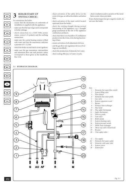
ES PL TR CZ SI HU RU RO IE SK UA 152 3 BOILER START-UP (INITIAL CHECK). To commission the boiler: - ensure that the declaration of conformity of installation is supplied with the appliance; - make sure that the type of gas used corresponds to boiler settings; - check connection to a 230V-50Hz power mains, correct L-N polarity and the earthing connection; - make sure the central heating system is filled with water and that the manometer indicates a pressure of 1÷1.2 bar. - switch the boiler on and check correct ignition; - make sure the gas maximum, intermediate and minimum flow rate and pressure values correspond to those given in the handbook, Par. 3.18; 3.1 HYDRAULIC DIAGRAM. - check activation of the safety device in the event of no gas, as well as the relative activation time; - check activation of the main switch located upstream from the boiler; - check the existing draught during normal functioning of the appliance, e.g. a draught gauge positioned at the exit of the appliance combustion products; - check that there is no backflow of combustion products into the room, even during functioning of fans; - ensure activation of all adjustment devices; - seal the gas flow rate regulation devices (if settings are modified); - check the production of domestic hot water; - check sealing efficiency of water circuits; - check ventilation and/or aeration of the installation room where provided. If any checks/inspection give negative results, do not start the boiler. Key: 1 - Domestic hot water flow switch 2 - System filling valve 3 - Flow limiter 4 - Domestic hot water probe 5 - Gas valve 6 - System expansion vessel 7 - Burner 8 - Primary heat exchanger 9 - Flue hood 10 - Flue safety thermostat 11 - Safety thermostat 12 - Delivery probe 13 - Vent valve 14 - Boiler pump 15 - System draining valve 16 - System pressure switch 17 - DHW. heat exchanger 18 - Three-way valve (motorised) 19 - By-pass 20 - 3 bar safety valve G - Gas supply AC - Domestic hot water outlet AF - Domestic cold water inlet R - System return M - System flow Fig. 3-1
3.2 WIRING DIAGRAM. 4 5 3 6 Key: B1 - Flow probe B2 - Domestic hot water probe B4 - External probe CAR V2 - Comando Amico Remoto remote control Version 2 (optional) DS1 - Display E3 - Ignition and detection electrodes E4 - Safety thermostat E6 - Flue safety thermostat F1 - Phase fuse M1 - Boiler pump The boiler is designed for application of a room thermostat (S20), an On/Off room chronothermostat, a program timer or a Comando Amico Remoto remote control V2 (CAR V2 ). Connect to clamps 40 - 41 eliminating the jumper X40, paying attention not to invert the polarity if the CAR V2 is installed. The connector X8 is used for the connection of the Virgilio Palmtop in the microprocessor software updating operation. 3.3 TROUBLESHOOTING. N.B.: Maintenance must be carried out by a qualified technician (e.g. Immergas Technical After-Sales Assistance Service). - Smell of gas. Caused by leakage from gas circuit pipelines. Check sealing efficiency of gas intake circuit. - Irregular combustion (red or yellow flame). When the burner is dirty or the boiler lamellar pack is blocked. Clean the burner or the boiler lamellar pack. 4 5 2 4 5 8 9 4 7 5 M30 - Three-way valve S2 - Selector switch functioning S3 - Reset block key S4 - Domestic hot water flow switch S5 - System pressure switch S20 - Room thermostat (optional) S21 - Domestic hot water temperature increase key S22 - Domestic hot water temperature decrease key S23 - Heating temperature increase key S24 - Heating temperature reduce key - Frequent interventions of the over heating safety thermostat. It can depend on the lack of water in the boiler, little water circulation in the system or blocked pump. Check on the manometer that the system pressure is within established limits. Check that the radiator valves are not closed and also the functionality of the pump. - The boiler produces condensate. This can be caused by obstructions of the chimney or flues with height or section not proportioned to the boiler. It can also be determined by functioning at boiler temperatures that are excessively low. In this case, make the boiler run at higher temperatures. - Frequent interventions of the flue safety thermostat This can be caused by obstructions in the flue gas circuit. Check the flue. The flue may be obstructed or by height or section not suitable for the boiler. Ventilation may be insufficient (see room ventilation point). 1 7 7 10 10 11 11 12 12 7 7 13 13 10 10 T1 - Low voltage feeder T2 - Switch-on transformer U1 - Rectifier inside the gas valve connector (Only available on Honeywell gas valves) X40 - Room thermostat jumper Y1 - Gas valve Y2 - Gas valve modulator 1 - User interface 2 - N.B.: The user interface is on the welding side of the boiler board 3 - 230 Vac 50Hz power supply 4 - Blue 5 - Brown 6 - Yellow/Green 7 - Black 8 - (DHW) 9 - (central heating) 10 - Grey 11 - White 12 - Red 13 - Green Fig. 3-2 - Presence of air in the system. Check opening of the hood of the special air vent valve (Fig. 1-10). Make sure the system pressure and expansion vessel pre-charge values are within the set limits; the pre-charge value for the expansion vessel must be 1.0 bar, and system pressure between 1 and 1.2 bar. - Ignition block and Chimney block. (See par. 2.6 and 1.3 (electric connection). ES PL TR CZ SI HU RU RO IE SK UA 153
- Page 104 and 105: ES PL TR CZ SI HU RU RO IE SK UA 10
- Page 106 and 107: ES PL TR CZ SI HU RU RO IE SK UA 10
- Page 108 and 109: ES PL TR CZ SI HU RU RO IE SK UA 10
- Page 110 and 111: ES PL TR CZ SI HU RU RO IE SK UA 10
- Page 112 and 113: ES PL TR CZ SI HU RU RO IE SK UA 11
- Page 114 and 115: ES PL TR CZ SI HU RU RO IE SK UA 11
- Page 116 and 117: ES PL TR CZ SI HU RU RO IE SK UA 11
- Page 118 and 119: ES PL TR CZ SI HU RU RO IE SK UA 11
- Page 120 and 121: ES PL TR CZ SI HU RU RO IE SK UA 11
- Page 122 and 123: ES PL TR CZ SI HU RU RO IE SK UA 12
- Page 124 and 125: ES PL TR CZ SI HU RU RO IE SK UA 12
- Page 126 and 127: ES PL TR CZ SI HU RU RO IE SK UA 12
- Page 128 and 129: ES PL TR CZ SI HU RU RO IE SK UA 12
- Page 130 and 131: ES PL TR CZ SI HU RU RO IE SK UA 12
- Page 132 and 133: ES PL TR CZ SI HU RU RO IE SK UA 13
- Page 134 and 135: ES PL TR CZ SI HU RU RO IE SK UA 13
- Page 136 and 137: ES PL TR CZ SI HU RU RO IE SK UA 13
- Page 138 and 139: ES PL TR CZ SI HU RU RO IE SK UA 13
- Page 140 and 141: ES PL TR CZ SI HU RU RO IE SK UA 13
- Page 142 and 143: ES PL TR CZ SI HU RU RO IE SK UA 14
- Page 144 and 145: LIVRET APARAT 1) (1) APARAT INDIVID
- Page 146 and 147: ES PL TR CZ SI HU RU RO IE SK UA 14
- Page 148 and 149: ES PL TR CZ SI HU RU RO IE SK UA 14
- Page 150 and 151: ES PL TR CZ SI HU RU RO IE SK UA 14
- Page 152 and 153: ES PL TR CZ SI HU RU RO IE SK UA 15
- Page 156 and 157: ES PL TR CZ SI HU RU RO IE SK UA 15
- Page 158 and 159: ES PL TR CZ SI HU RU RO IE SK UA 15
- Page 160 and 161: ES PL TR CZ SI HU RU RO IE SK UA 15
- Page 162 and 163: ES PL TR CZ SI HU RU RO IE SK UA 16
- Page 164 and 165: ES PL TR CZ SI HU RU RO IE SK UA 16
- Page 166 and 167: ES PL TR CZ SI HU RU RO IE SK UA 16
- Page 168 and 169: ES PL TR CZ SI HU RU RO IE SK UA 16
- Page 170 and 171: ES PL TR CZ SI HU RU RO IE SK UA 16
- Page 172 and 173: ES PL TR CZ SI HU RU RO IE SK UA 17
- Page 174 and 175: ES PL TR CZ SI HU RU RO IE SK UA 17
- Page 176 and 177: ES PL TR CZ SI HU RU RO IE SK UA 17
- Page 178 and 179: ES PL TR CZ SI HU RU RO IE SK UA 17
- Page 180 and 181: ES PL TR CZ SI HU RU RO IE SK UA 17
- Page 182 and 183: ES PL TR CZ SI HU RU RO IE SK UA 18
- Page 184 and 185: ES PL TR CZ SI HU RU RO IE SK UA 18
- Page 186 and 187: ES PL TR CZ SI HU RU RO IE SK UA 18
- Page 188 and 189: ES PL TR CZ SI HU RU RO IE SK UA 18
- Page 190 and 191: ES PL TR CZ SI HU RU RO IE SK UA 18
- Page 192 and 193: ES PL TR CZ SI HU RU RO IE SK UA 19
- Page 194 and 195: ES PL TR CZ SI HU RU RO IE SK UA 19
- Page 196: ES PL TR CZ SI HU RU RO IE SK UA 19
ES<br />
PL<br />
TR<br />
CZ<br />
SI<br />
HU<br />
RU<br />
RO<br />
IE<br />
SK<br />
UA<br />
152<br />
3 BOILER<br />
START-UP<br />
(INITIAL CHECK).<br />
To commission the boiler:<br />
- ensure that the declaration of conformity of<br />
installation is supplied with the appliance;<br />
- make sure that the type of gas used corresponds<br />
to boiler settings;<br />
- check connection to a 230V-50Hz power<br />
mains, correct L-N polarity and the earthing<br />
connection;<br />
- make sure the central heating system is filled<br />
with water and that the manometer indicates<br />
a pressure of 1÷1.2 bar.<br />
- switch the boiler on and check correct ignition;<br />
- make sure the gas maximum, intermediate<br />
and minimum flow rate and pressure values<br />
correspond to those given in the handbook,<br />
Par. 3.18;<br />
3.1 HYDRAULIC DIAGRAM.<br />
- check activation of the safety device in the<br />
event of no gas, as well as the relative activation<br />
time;<br />
- check activation of the main switch located<br />
upstream from the boiler;<br />
- check the existing draught during normal<br />
functioning of the appliance, e.g. a draught<br />
gauge positioned at the exit of the appliance<br />
combustion products;<br />
- check that there is no backflow of combustion<br />
products into the room, even during functioning<br />
of fans;<br />
- ensure activation of all adjustment devices;<br />
- seal the gas flow rate regulation devices (if settings<br />
are modified);<br />
- check the production of domestic hot water;<br />
- check sealing efficiency of water circuits;<br />
- check ventilation and/or aeration of the installation<br />
room where provided.<br />
If any checks/inspection give negative results, do<br />
not start the boiler.<br />
Key:<br />
1 - Domestic hot water flow switch<br />
2 - System filling valve<br />
3 - Flow limiter<br />
4 - Domestic hot water probe<br />
5 - Gas valve<br />
6 - System expansion vessel<br />
7 - Burner<br />
8 - Primary heat exchanger<br />
9 - Flue hood<br />
10 - Flue safety thermostat<br />
11 - Safety thermostat<br />
12 - Delivery probe<br />
13 - Vent valve<br />
14 - Boiler pump<br />
15 - System draining valve<br />
16 - System pressure switch<br />
17 - DHW. heat exchanger<br />
18 - Three-way valve (motorised)<br />
19 - By-pass<br />
20 - 3 bar safety valve<br />
G - Gas supply<br />
AC - Domestic hot water outlet<br />
AF - Domestic cold water inlet<br />
R - System return<br />
M - System flow<br />
Fig. 3-1


