MINI Nike X 24 3 E - Immergas
MINI Nike X 24 3 E - Immergas MINI Nike X 24 3 E - Immergas
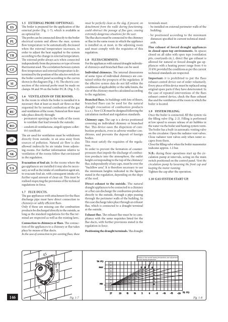
ES PL TR CZ SI HU RU RO IE SK UA 146 1.5 EXTERNAL PROBE (OPTIONAL). The boiler is prepared for the application of the external probe (Fig. 1-7), which is available as an optional kit. The probe can be connected directly to the boiler electrical system and allows the max. system flow temperature to be automatically decreased when the external temperature increases, in order to adjust the heat supplied to the system according to the change in external temperature. The external probe always acts when connected independently from the presence or type of room thermostat used. The correlation between system flow temperature and external temperature is determined by the position of the selector switch on the boiler control panel according to the curves shown in the diagram (Fig. 1-8). The electric connection of the external probe must be made on clamps 38 and 39 on the boiler P.C.B. (Fig. 3-2). 1.6 VENTILATION OF THE ROOMS. In the room in which the boiler is installed it is necessary that at least as much air flows as that requested for by normal combustion of the gas and ventilation of the room. Natural air flow must take place directly through: - permanent openings in the walls of the room to ventilate that lead towards the outside; - condotti di ventilazione, singoli oppure collettivi ramificati. The air used for ventilation must be withdrawn directly from outside, in an area away from sources of pollution. Natural air flow is also allowed indirectly by air intake from adjoining rooms. For further information relative to ventilation of the rooms follow that envisioned in the regulation. Evacuation of foul air. In the rooms where the gas appliances are installed it may also be necessary, as well as the intake of combustion agent air, to evacuate foul air, with consequent intake of a further equal amount of clean air. This must be realised respecting the provisions of the technical regulations in force. 1.7 FLUE DUCTS. The gas appliances with attachment for the flues discharge pipe must have direct connection to chimneys or safely efficient flues. Only if these are missing can the combustion products be discharged directly to the outside, as long as the standard regulations for the flue terminal are respected as well as the existing laws. Connection to chimneys or flues. The connection of the appliances to a chimney or flue takes place by means of flue ducts. In the case of connection to pre-existing flues, these 31 45 58 must be perfectly clean as the slag, if present, on detachment from the walls during functioning, could obstruct the passage of flue gass, causing extremely dangerous situations for the user. The flue ducts must be connected to the chimney or flue in the same room in which the appliance is installed or, at most, in the adjoining room and must comply with the requisites of this regulation. 1.8 FLUES/CHIMNEYS. For the appliances with natural draught individual chimneys and branched flues can be used. Individual chimneys. The internal dimensions of some types of individual chimneys are contained within the prospects of the regulation. If the effective system data do not fall within the conditions of applicability or the table limits, the size of the chimney must be calculated according to the regulation. Branched flues. In buildings with lots of floors, branched flues can be used for the natural draught evacuation of combustion products (c.c.r.). New CCR must be designed following the calculation method and regulation standards. Chimney caps. The cap is a device positioned crowning an individual chimney or branched flue. This device eases the dispersion of combustion products, even in adverse weather conditions, and prevents the deposit of foreign bodies. This must satisfy the requisites of the regulation. In order to prevent the formation of counterpressures that impede the discharge of combustion products into the atmosphere, the outlet height corresponding to the top of the chimney/ flue, independently of any caps, must be over the “backflow area”. It is therefore necessary to use the minimum heights indicated in the figures stated in the regulation, depending on the slope of the roof. Direct exhaust to the outside. The natural draught appliances to be connected to a chimney or a flue can discharge the combustion products directly to the outside, through a pipe passing through the perimeter walls of the building. In this case discharge takes place through an exhaust flue, which is connected to a draught terminal at the outside. Exhaust flue. The exhaust flue must be in compliance with the same requisites listed for the flue ducts, with further provisions stated in the regulation in force. Positioning the draught terminals. The draught terminals must: - be installed on external perimeter walls of the building; - be positioned according to the minimum distances specified in current technical standards. Flue exhaust of forced draught appliances in closed open-top environments. In spaces closed on all sides with open tops (ventilation pits, courtyards etc.), direct flue gas exhaust is allowed for natural or forced draught gas appliances with a heating power range from 4 to 35 kW, provided the conditions as per the current technical standards are respected. Important: it is prohibited to put the flues exhaust control device out of order voluntarily. Every piece of this device must be replaced using original spare parts if they have deteriorated. In the case of repeated interventions of the flues exhaust control device, check the flues exhaust flue and the ventilation of the room in which the boiler is located. 1.9 SYSTEM FILLING. Once the boiler is connected, fill the system via the filling valve (Fig. 2-2). Filling is performed at low speed to ensure release of air bubbles in the water via the boiler and heating system vents. The boiler has a built-in automatic venting valve on the circulator. Open the radiator vent valves. Close radiator vent valves only when water escapes from them. Close the filling valve when the boiler manometer indicates approx. 1.2 bar. N.B.: during these operations start up the circulation pump at intervals, acting on the main switch positioned on the control panel. Vent the circulation pump by loosening the front cap and keeping the motor running. Tighten the cap after the operation. 1.10 GAS SYSTEM START-UP. Position of the central heating temperature user adjustment central heating temperature Fig. 1-7 Fig. 1-8
To start up the system proceed as follows: - open windows and doors; - avoid presence of sparks or naked flames; - bleed all air from pipelines; - check that the internal system is properly sealed according to specifications. 1.11 BOILER START UP (IGNITION). For issue of the envisioned Declaration of Conformity, the following must be performed for boiler start-up: - check that the internal system is properly sealed according to specifications - make sure that the type of gas used corresponds to boiler settings; - switch the boiler on and check correct ignition; - make sure that the gas flow rate and relevant pressure values comply with those given in the manual (par. 3.18); - check the correct ventilation of the rooms; - check the existing draught during normal functioning of the appliance, e.g. a draught gauge positioned at the exit of the appliance combustion products; - check that there is no backflow of combustion products into the room, even during functioning of fans; - ensure that the safety device is engaged in the event of gas supply failure and check activation time; - check activation of the main switch located upstream from the boiler. The boiler must not be started up even if only one of the checks should be negative. N.B.: the boiler preliminary check must be carried out by a qualified technician. The conventional boiler warranty is valid as of the date of testing. The test certificate and warranty is issued to the user. 1.12 CIRCULATION PUMP. Total head available to the system. Head (kPa) D B The Mini Nike X 24 3 E series boilers are supplied with a built-in circulation pump with 3-position electric speed control. The boiler does not operate correctly with the circulation pump on first speed. To ensure optimal boiler operation, in the case of new systems (single pipe and module) it is recommended to use the pump at maximum speed. The pump is already fitted with a condenser. Pump release. If, after a prolonged period of inactivity, the circulation pump is blocked, unscrew the front cap and turn the motor shaft using a screwdriver. Take great care during this operation to avoid damage to the motor. By-pass regulation (part. 20 Fig. 1-10). If necessary, the by-pass can be regulated according to system requirements from a minimum (by-pass excluded) to a maximum (by-pass inserted) represented by the graphics (Fig. 1-9). Make the regulation using a flat head screwdriver, turn clockwise and insert the by-pass, anti-clockwise it is excluded. 1.13 KITS AVAILABLE ON REQUEST. • System shut off valves kit. The boiler is designed for installation of system interception cocks to be placed on flow and return pipes of the connection assembly. This kit is particularly useful for maintenance as it allows the boiler to be drained separately without having to empty the entire system. C • Polyphosphate dispenser kit. The polyphosphate dispenser reduces the formation of limescale and preserves the original heat exchange and domestic hot water production conditions. The boiler is prepared for application of the polyphosphate dispenser kit. • External storage tank unit coupling kit. If the A Flow rate (l/h) production of DHW is required as well as room central heating, on request Immergas supplies a kit made up from an external cylinder unit and everything necessary for adaptation of the boiler The above-mentioned kits are supplied complete with instructions for assembly and use. Total head (m H 2 O) A = Head available to the system at maximum speed with by-pass excluded. B = Head available to the system at maximum speed with by-pass inserted. C = Head available to the system at second speed with by-pass excluded. D = Head available to the system at second speed with by-pass inserted. Fig. 1-9 ES PL TR CZ SI HU RU RO IE SK UA 147
- Page 98 and 99: ES PL TR CZ SI HU RU RO IE SK UA 96
- Page 100 and 101: ES PL TR CZ SI HU RU RO IE SK UA 98
- Page 102 and 103: ES PL TR CZ SI HU RU RO IE SK UA 10
- Page 104 and 105: ES PL TR CZ SI HU RU RO IE SK UA 10
- Page 106 and 107: ES PL TR CZ SI HU RU RO IE SK UA 10
- Page 108 and 109: ES PL TR CZ SI HU RU RO IE SK UA 10
- Page 110 and 111: ES PL TR CZ SI HU RU RO IE SK UA 10
- Page 112 and 113: ES PL TR CZ SI HU RU RO IE SK UA 11
- Page 114 and 115: ES PL TR CZ SI HU RU RO IE SK UA 11
- Page 116 and 117: ES PL TR CZ SI HU RU RO IE SK UA 11
- Page 118 and 119: ES PL TR CZ SI HU RU RO IE SK UA 11
- Page 120 and 121: ES PL TR CZ SI HU RU RO IE SK UA 11
- Page 122 and 123: ES PL TR CZ SI HU RU RO IE SK UA 12
- Page 124 and 125: ES PL TR CZ SI HU RU RO IE SK UA 12
- Page 126 and 127: ES PL TR CZ SI HU RU RO IE SK UA 12
- Page 128 and 129: ES PL TR CZ SI HU RU RO IE SK UA 12
- Page 130 and 131: ES PL TR CZ SI HU RU RO IE SK UA 12
- Page 132 and 133: ES PL TR CZ SI HU RU RO IE SK UA 13
- Page 134 and 135: ES PL TR CZ SI HU RU RO IE SK UA 13
- Page 136 and 137: ES PL TR CZ SI HU RU RO IE SK UA 13
- Page 138 and 139: ES PL TR CZ SI HU RU RO IE SK UA 13
- Page 140 and 141: ES PL TR CZ SI HU RU RO IE SK UA 13
- Page 142 and 143: ES PL TR CZ SI HU RU RO IE SK UA 14
- Page 144 and 145: LIVRET APARAT 1) (1) APARAT INDIVID
- Page 146 and 147: ES PL TR CZ SI HU RU RO IE SK UA 14
- Page 150 and 151: ES PL TR CZ SI HU RU RO IE SK UA 14
- Page 152 and 153: ES PL TR CZ SI HU RU RO IE SK UA 15
- Page 154 and 155: ES PL TR CZ SI HU RU RO IE SK UA 15
- Page 156 and 157: ES PL TR CZ SI HU RU RO IE SK UA 15
- Page 158 and 159: ES PL TR CZ SI HU RU RO IE SK UA 15
- Page 160 and 161: ES PL TR CZ SI HU RU RO IE SK UA 15
- Page 162 and 163: ES PL TR CZ SI HU RU RO IE SK UA 16
- Page 164 and 165: ES PL TR CZ SI HU RU RO IE SK UA 16
- Page 166 and 167: ES PL TR CZ SI HU RU RO IE SK UA 16
- Page 168 and 169: ES PL TR CZ SI HU RU RO IE SK UA 16
- Page 170 and 171: ES PL TR CZ SI HU RU RO IE SK UA 16
- Page 172 and 173: ES PL TR CZ SI HU RU RO IE SK UA 17
- Page 174 and 175: ES PL TR CZ SI HU RU RO IE SK UA 17
- Page 176 and 177: ES PL TR CZ SI HU RU RO IE SK UA 17
- Page 178 and 179: ES PL TR CZ SI HU RU RO IE SK UA 17
- Page 180 and 181: ES PL TR CZ SI HU RU RO IE SK UA 17
- Page 182 and 183: ES PL TR CZ SI HU RU RO IE SK UA 18
- Page 184 and 185: ES PL TR CZ SI HU RU RO IE SK UA 18
- Page 186 and 187: ES PL TR CZ SI HU RU RO IE SK UA 18
- Page 188 and 189: ES PL TR CZ SI HU RU RO IE SK UA 18
- Page 190 and 191: ES PL TR CZ SI HU RU RO IE SK UA 18
- Page 192 and 193: ES PL TR CZ SI HU RU RO IE SK UA 19
- Page 194 and 195: ES PL TR CZ SI HU RU RO IE SK UA 19
- Page 196: ES PL TR CZ SI HU RU RO IE SK UA 19
ES<br />
PL<br />
TR<br />
CZ<br />
SI<br />
HU<br />
RU<br />
RO<br />
IE<br />
SK<br />
UA<br />
146<br />
1.5 EXTERNAL PROBE (OPTIONAL).<br />
The boiler is prepared for the application of the<br />
external probe (Fig. 1-7), which is available as<br />
an optional kit.<br />
The probe can be connected directly to the boiler<br />
electrical system and allows the max. system<br />
flow temperature to be automatically decreased<br />
when the external temperature increases, in<br />
order to adjust the heat supplied to the system<br />
according to the change in external temperature.<br />
The external probe always acts when connected<br />
independently from the presence or type of room<br />
thermostat used. The correlation between system<br />
flow temperature and external temperature is determined<br />
by the position of the selector switch on<br />
the boiler control panel according to the curves<br />
shown in the diagram (Fig. 1-8). The electric connection<br />
of the external probe must be made on<br />
clamps 38 and 39 on the boiler P.C.B. (Fig. 3-2).<br />
1.6 VENTILATION OF THE ROOMS.<br />
In the room in which the boiler is installed it is<br />
necessary that at least as much air flows as that<br />
requested for by normal combustion of the gas<br />
and ventilation of the room. Natural air flow must<br />
take place directly through:<br />
- permanent openings in the walls of the room<br />
to ventilate that lead towards the outside;<br />
- condotti di ventilazione, singoli oppure collettivi<br />
ramificati.<br />
The air used for ventilation must be withdrawn<br />
directly from outside, in an area away from<br />
sources of pollution. Natural air flow is also<br />
allowed indirectly by air intake from adjoining<br />
rooms. For further information relative to<br />
ventilation of the rooms follow that envisioned<br />
in the regulation.<br />
Evacuation of foul air. In the rooms where the<br />
gas appliances are installed it may also be necessary,<br />
as well as the intake of combustion agent air,<br />
to evacuate foul air, with consequent intake of a<br />
further equal amount of clean air. This must be<br />
realised respecting the provisions of the technical<br />
regulations in force.<br />
1.7 FLUE DUCTS.<br />
The gas appliances with attachment for the flues<br />
discharge pipe must have direct connection to<br />
chimneys or safely efficient flues.<br />
Only if these are missing can the combustion<br />
products be discharged directly to the outside, as<br />
long as the standard regulations for the flue terminal<br />
are respected as well as the existing laws.<br />
Connection to chimneys or flues. The connection<br />
of the appliances to a chimney or flue takes<br />
place by means of flue ducts.<br />
In the case of connection to pre-existing flues, these<br />
31<br />
45<br />
58<br />
must be perfectly clean as the slag, if present, on<br />
detachment from the walls during functioning,<br />
could obstruct the passage of flue gass, causing<br />
extremely dangerous situations for the user.<br />
The flue ducts must be connected to the chimney<br />
or flue in the same room in which the appliance<br />
is installed or, at most, in the adjoining room<br />
and must comply with the requisites of this<br />
regulation.<br />
1.8 FLUES/CHIMNEYS.<br />
For the appliances with natural draught individual<br />
chimneys and branched flues can be used.<br />
Individual chimneys. The internal dimensions<br />
of some types of individual chimneys are contained<br />
within the prospects of the regulation. If<br />
the effective system data do not fall within the<br />
conditions of applicability or the table limits, the<br />
size of the chimney must be calculated according<br />
to the regulation.<br />
Branched flues. In buildings with lots of floors,<br />
branched flues can be used for the natural<br />
draught evacuation of combustion products<br />
(c.c.r.). New CCR must be designed following the<br />
calculation method and regulation standards.<br />
Chimney caps. The cap is a device positioned<br />
crowning an individual chimney or branched<br />
flue. This device eases the dispersion of combustion<br />
products, even in adverse weather conditions,<br />
and prevents the deposit of foreign<br />
bodies.<br />
This must satisfy the requisites of the regulation.<br />
In order to prevent the formation of counterpressures<br />
that impede the discharge of combustion<br />
products into the atmosphere, the outlet<br />
height corresponding to the top of the chimney/<br />
flue, independently of any caps, must be over the<br />
“backflow area”. It is therefore necessary to use<br />
the minimum heights indicated in the figures<br />
stated in the regulation, depending on the slope<br />
of the roof.<br />
Direct exhaust to the outside. The natural<br />
draught appliances to be connected to a chimney<br />
or a flue can discharge the combustion products<br />
directly to the outside, through a pipe passing<br />
through the perimeter walls of the building. In<br />
this case discharge takes place through an exhaust<br />
flue, which is connected to a draught terminal<br />
at the outside.<br />
Exhaust flue. The exhaust flue must be in compliance<br />
with the same requisites listed for the<br />
flue ducts, with further provisions stated in the<br />
regulation in force.<br />
Positioning the draught terminals. The draught<br />
terminals must:<br />
- be installed on external perimeter walls of the<br />
building;<br />
- be positioned according to the minimum<br />
distances specified in current technical standards.<br />
Flue exhaust of forced draught appliances<br />
in closed open-top environments. In spaces<br />
closed on all sides with open tops (ventilation<br />
pits, courtyards etc.), direct flue gas exhaust is<br />
allowed for natural or forced draught gas appliances<br />
with a heating power range from 4 to<br />
35 kW, provided the conditions as per the current<br />
technical standards are respected.<br />
Important: it is prohibited to put the flues<br />
exhaust control device out of order voluntarily.<br />
Every piece of this device must be replaced using<br />
original spare parts if they have deteriorated. In<br />
the case of repeated interventions of the flues<br />
exhaust control device, check the flues exhaust<br />
flue and the ventilation of the room in which the<br />
boiler is located.<br />
1.9 SYSTEM FILLING.<br />
Once the boiler is connected, fill the system via<br />
the filling valve (Fig. 2-2). Filling is performed<br />
at low speed to ensure release of air bubbles in<br />
the water via the boiler and heating system vents.<br />
The boiler has a built-in automatic venting valve<br />
on the circulator. Open the radiator vent valves.<br />
Close radiator vent valves only when water escapes<br />
from them.<br />
Close the filling valve when the boiler manometer<br />
indicates approx. 1.2 bar.<br />
N.B.: during these operations start up the circulation<br />
pump at intervals, acting on the main<br />
switch positioned on the control panel. Vent the<br />
circulation pump by loosening the front cap and<br />
keeping the motor running.<br />
Tighten the cap after the operation.<br />
1.10 GAS SYSTEM START-UP.<br />
Position of the central heating temperature user adjustment<br />
central heating temperature<br />
Fig. 1-7 Fig. 1-8


