PDM1027 - FERM.com
PDM1027 - FERM.com PDM1027 - FERM.com
EN IMPACT DRILL PDM1027 Thank you for buying this Ferm product. By doing so you now have an excellent product, delivered by one of Europe‘s leading suppliers. All products delivered to you by Ferm are manufactured according to the highest standards of performance and safety. As part of our philosophy we also provide an excellent customer service, backed by our comprehensive warranty. We hope you will enjoy using this product for many years to come. SAFETy wARnIngS 1 WARNING Read the enclosed safety warnings, the additional safety warnings and the instructions. Failure to follow the safety warnings and the instructions may result in electric shock, fire and/or serious injury. Keep the safety warnings and the instructions for future reference. The following symbols are used in the user manual or on the product: 1 2 3 4 5 A I D 7 4 Read the user manual. Risk of personal injury. Risk of electric shock. Immediately remove the mains plug from the mains if the mains cable becomes damaged and during cleaning and maintenance. Wear safety goggles. Wear hearing protection. Wear a dust mask. Wear safety gloves. Variable electronic speed. Double insulated. 8 9 Do not dispose of the product in unsuitable containers. The product is in accordance with the applicable safety standards in the European directives. Additional safety warnings for impact drills ● Do not work materials containing asbestos. Asbestos is considered carcinogenic. ● Wear safety goggles. ● Wear hearing protection to avoid the risk of hearing loss. ● If necessary, use other protective means, such as safety gloves, safety shoes, etc. ● Hold the machine with one hand on the main grip and the other hand on the auxiliary grip. Risk of personal injury. ● Hold the machine by the insulated gripping surfaces where the accessory may contact hidden wiring or the mains cable. If the accessory contacts a ‚live‘ wire, the exposed metal parts of the machine can also become ‚live‘. Risk of electric shock. ● Do not use accessories which are not specifically designed and recommended by the manufacturer. Risk of personal injury. ● Only use accessories that are suitable for use with the machine. ● Only use accessories with the correct dimensions. Make sure that the accessories are properly mounted. ● Inspect the machine and the accessories before each use. Do not use accessories which are bent, cracked, or otherwise damaged. If the machine or one of the accessories is dropped, inspect the machine or the accessory for damage. If necessary, replace the accessory. ● Let the machine run at no load in a safe area after mounting the accessories. If the machine vibrates strongly, immediately switch off the machine, remove the mains plug from the mains, and try to solve the problem. ● Make sure that the maximum speed for the accessory is larger than or the same as the maximum speed of the machine. Refer to the rating plate on the machine. ● Before use, remove all nails and other metal objects from the workpiece. ● Make sure that the workpiece is properly supported or fixed. ● Keep your hands away from the workpiece during use.
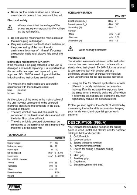
● Never put the machine down on a table or a workbench before it has been switched off. Electrical safety 3 Always check that the voltage of the power supply corresponds to the voltage on the rating plate. ● Do not use the machine if the mains cable or the mains plug is damaged. ● Only use extension cables that are suitable for the power rating of the machine with a minimum thickness of 1.5 mm 2 . If you use a extension cable reel, always fully unroll the cable. Mains plug replacement (UK only) If the moulded 3-pin plug attached to the unit is damaged and needs replacing, it is important that it is correctly destroyed and replaced by an approved BS 1363/5A fused plug and that the following wiring instructions are followed. The wires in the mains cable are coloured in accordance with the following code: blue neutral brown live As the colours of the wires in the mains cable of the unit may not correspond to the coloured markings identifying the terminals in the plug, proceed as follows: - The wire which is coloured blue must be connected to the terminal which is marked with the letter N or coloured black. - The wire which is coloured brown must be connected to the terminal which is marked with the letter L or coloured red. TECHNICAL DATA PDM1027 Mains voltage V~ 230 Mains frequency Hz 50 Power input W 710 No-load speed min -1 0 - 2,700 Impact rate min -1 0 - 43,200 Max. drill bit diameter Wood mm 25 Concrete mm 13 Steel mm 10 Protection class IP 20 Weight kg 1.9 NOISE AND VIBRATION PDM1027 Sound pressure (L pa ) dB(A) 91 Acoustic power (L wa ) dB(A) 102 Uncertainty (K) dB(A) 3 Vibration Metal m/s 2 14.27 Concrete m/s 2 3.50 Uncertainty (K) m/s 2 1.5 2 Wear hearing protection. Vibration level The vibration emission level stated in this instruction manual has been measured in accordance with a standardised test given in EN 60745; it may be used to compare one tool with another and as a preliminary assessment of exposure to vibration when using the tool for the applications mentioned - using the tool for different applications, or with different or poorly maintainted accessories, may significantly increase the exposure level - the times when the tool is switched off or when it is running but not actually doing the job, may significantly reduce the exposure level Protect yourself against the effects of vibration by maintaining the tool and its accessories, keeping your hands warm, and organizing your work patterns DESCRIPTION (fIg. A) Your impact drill has been designed for drilling holes in wood, metal and plastics and for hammer drilling in brick and concrete. 1. On/off switch 2. Lock-on button 3. Speed adjustment wheel 4. Forward/reverse switch 5. Switch for drilling / hammer drilling 6. Chuck 7. Main grip 8. Auxiliary grip 9. Depth stop 10. Storage system (drill bits) 5 EN
- Page 1 and 2: EN DE NL FR ES PT IT SV FI NO DA HU
- Page 3: B D 11 6 12 9 8 8 5 6 11 8 13 12 14
- Page 7 and 8: CLEAnIng AnD MAInTEnAnCE 4 Before c
- Page 9 and 10: LÄRM UND VIBRATIONEN PDM1027 Schal
- Page 11 and 12: ● Bringen Sie die Abdeckung (14)
- Page 13 and 14: Trillingsniveau Het trillingsemissi
- Page 15 and 16: PERCEUSE À PERCUSSIOn PDM1027 Merc
- Page 17 and 18: Montage ● Ouvrez le mandrin (6) e
- Page 19 and 20: TALADRO PERCUTOR PDM1027 Gracias po
- Page 21 and 22: - Madera (HSS) - Metal (HSS) - Horm
- Page 23 and 24: BERBEQUIM DE IMPACTO PDM1027 Obriga
- Page 25 and 26: Montagem ● Abra a bucha (6) rodan
- Page 27 and 28: D 7 8 9 Velocità variabile elettro
- Page 29 and 30: Montaggio ● Allentare l‘impugna
- Page 31 and 32: 7 8 9 Dubbelisolerad. Släng inte p
- Page 33 and 34: fram-/backomkopplare (fig. A) 2 Än
- Page 35 and 36: ● Älä koskaan aseta konetta ty
- Page 37 and 38: SÄILYTYS (KUVA f) Koneessa on erit
- Page 39 and 40: - bruk av verktøyet til andre oppg
- Page 41 and 42: SLAgBOREMASKInE PDM1027 Tak for, at
- Page 43 and 44: ● Sæt boret (12) ind i patronen
- Page 45 and 46: 7 8 9 Kétszeresen szigetelt. A ter
- Page 47 and 48: Előre/hátra kapcsoló (A. ábra)
- Page 49 and 50: ● Nikdy neodkládejte stroj na st
- Page 51 and 52: SKLADOVÁNÍ (OBR. f) Tento stroj j
- Page 53 and 54: - používanie náradia na rôzne a
● Never put the machine down on a table or<br />
a workbench before it has been switched off.<br />
Electrical safety<br />
3<br />
Always check that the voltage of the<br />
power supply corresponds to the voltage<br />
on the rating plate.<br />
● Do not use the machine if the mains cable or<br />
the mains plug is damaged.<br />
● Only use extension cables that are suitable for<br />
the power rating of the machine with<br />
a minimum thickness of 1.5 mm 2 . If you use<br />
a extension cable reel, always fully unroll the<br />
cable.<br />
Mains plug replacement (UK only)<br />
If the moulded 3-pin plug attached to the unit is<br />
damaged and needs replacing, it is important that<br />
it is correctly destroyed and replaced by an<br />
approved BS 1363/5A fused plug and that the<br />
following wiring instructions are followed.<br />
The wires in the mains cable are coloured in<br />
accordance with the following code:<br />
blue neutral<br />
brown live<br />
As the colours of the wires in the mains cable of<br />
the unit may not correspond to the coloured<br />
markings identifying the terminals in the plug,<br />
proceed as follows:<br />
- The wire which is coloured blue must be<br />
connected to the terminal which is marked with<br />
the letter N or coloured black.<br />
- The wire which is coloured brown must be<br />
connected to the terminal which is marked with<br />
the letter L or coloured red.<br />
TECHNICAL DATA<br />
<strong>PDM1027</strong><br />
Mains voltage V~ 230<br />
Mains frequency Hz 50<br />
Power input W 710<br />
No-load speed min -1 0 - 2,700<br />
Impact rate min -1 0 - 43,200<br />
Max. drill bit diameter<br />
Wood mm 25<br />
Concrete mm 13<br />
Steel mm 10<br />
Protection class IP 20<br />
Weight kg 1.9<br />
NOISE AND VIBRATION<br />
<strong>PDM1027</strong><br />
Sound pressure (L pa ) dB(A) 91<br />
Acoustic power (L wa ) dB(A) 102<br />
Uncertainty (K) dB(A) 3<br />
Vibration<br />
Metal m/s 2 14.27<br />
Concrete m/s 2 3.50<br />
Uncertainty (K) m/s 2 1.5<br />
2<br />
Wear hearing protection.<br />
Vibration level<br />
The vibration emission level stated in this instruction<br />
manual has been measured in accordance with a<br />
standardised test given in EN 60745; it may be used<br />
to <strong>com</strong>pare one tool with another and as a<br />
preliminary assessment of exposure to vibration<br />
when using the tool for the applications mentioned<br />
- using the tool for different applications, or with<br />
different or poorly maintainted accessories,<br />
may significantly increase the exposure level<br />
- the times when the tool is switched off or when<br />
it is running but not actually doing the job, may<br />
significantly reduce the exposure level<br />
Protect yourself against the effects of vibration by<br />
maintaining the tool and its accessories, keeping<br />
your hands warm, and organizing your work<br />
patterns<br />
DESCRIPTION (fIg. A)<br />
Your impact drill has been designed for drilling<br />
holes in wood, metal and plastics and for hammer<br />
drilling in brick and concrete.<br />
1. On/off switch<br />
2. Lock-on button<br />
3. Speed adjustment wheel<br />
4. Forward/reverse switch<br />
5. Switch for drilling / hammer drilling<br />
6. Chuck<br />
7. Main grip<br />
8. Auxiliary grip<br />
9. Depth stop<br />
10. Storage system (drill bits)<br />
5<br />
EN


