VA/100.02 2401-3166 12.03 - TECH FASS sro
VA/100.02 2401-3166 12.03 - TECH FASS sro
VA/100.02 2401-3166 12.03 - TECH FASS sro

Create successful ePaper yourself
Turn your PDF publications into a flip-book with our unique Google optimized e-Paper software.
Dimensions are shown in figure 4A.<br />
It can also be surface mounted,<br />
using the DIN rail supplied, but fitted<br />
with terminal covers.<br />
Dimensions are shown in figure 4B.<br />
NOTE. Remove cover to reach<br />
fuses, figure 3.<br />
(Fuse: F =fast, T =slow).<br />
STARTING UP AND TESTING<br />
Preliminary checks with<br />
system switched off<br />
On completion of installation and<br />
before switching on the system,<br />
proceed as follows:<br />
1.Make sure that the monitor<br />
ON/OFF-brightness control functions<br />
correctly by turning the<br />
thumbwheel until it clicks on.<br />
2.If the system comprises several<br />
internal units activated by the<br />
same call, make sure that the dipswitches<br />
or jumpers are correctly<br />
positioned.<br />
3.If the system comprises several<br />
entry panels or auxiliary camera,<br />
make sure that the dip-switches on<br />
selector VSI/110 are set correctly.<br />
4.If the system comprises several<br />
internal units with intercom facility,<br />
the relative identification number<br />
must be allocated.<br />
On completion of these preliminary<br />
checks, switch on the system and<br />
proceed as indicated below.<br />
ENTRY PANEL<br />
1.Remove the front plate.<br />
2.Make sure that all the call buttons<br />
are correctly illuminated.<br />
3.Make the call.<br />
4.Check that the lighting system -<br />
subject illumination lamps - for the<br />
camera is working.<br />
5.Regulate the audio level of the 2<br />
channels using the appropriates<br />
potentiometers.<br />
6.While using the audio system,<br />
check with the monitor operator to<br />
see that the field of vision is adequate,<br />
if not, adjust the camera<br />
angle of view (where is possible).<br />
7.If the system has more than one<br />
monitor, check to see they are all<br />
working.<br />
8.Replace the front panel.<br />
NOTE. If the system has more than<br />
one entry panel, proceed with all in<br />
the same way as described above.<br />
MONITOR<br />
1.Check that when a call is made,<br />
the monitor is turned on and regulate<br />
the call tone level by turning<br />
the appropriate potentiometer, in<br />
the main control unit <strong>VA</strong>/100.<br />
2.With the help of an operator standing<br />
in front of the entry panel,<br />
check that the audio is functioning<br />
correctly.<br />
3.Check that the monitor running<br />
time is about 45 s.<br />
This period of time should be<br />
checked without lifting the handset<br />
or pushing the audio button on<br />
“hands-free” receivers.<br />
If you wish to adjust this time from<br />
15 to 60 s, regulate the appropriate<br />
potentiometer in the main control<br />
unit <strong>VA</strong>/100.<br />
4<br />
4.Check that the following system<br />
components are operating correctly:<br />
Stairs light<br />
Press this button (if included in the<br />
system and provided no other monitor<br />
is operating) to activate the stair,<br />
entrance and garden lights, etc.<br />
Switching on the entry<br />
panel from the monitor<br />
By pressing this button on monitor<br />
(if no other monitor is in use), the<br />
entry panel no. 1 will be activated.<br />
Switching on additional<br />
entry panels and surveillance<br />
cameras<br />
By pressing again this button, any<br />
additional entry panels and surveillance<br />
cameras (max. 10) will be<br />
activated and viewed in sequence.<br />
Door release<br />
The door lock release solenoid is<br />
activated by pressing this button on<br />
monitor (if no other monitor is use).<br />
1÷16 Intercom<br />
Press the intercom call buttons of<br />
each monitor, checking to see that<br />
the respective monitor is called<br />
and the audio is working.<br />
NOTE. If the system has more than<br />
one monitor, all operations listed<br />
above must be repeated for each<br />
one.<br />
This equipment has been tested<br />
and found to comply with the limits<br />
for a Class B digital device, pursuant<br />
to Part 15 of the FFC Rules.<br />
These limits are designed to provided<br />
reasonable protection against<br />
harmful interference when the<br />
equipment is operated in a commercial<br />
environment.<br />
This equipment generates, uses,<br />
and can radiate radio frequency<br />
energy and, if not installed and<br />
used in accordance whit the<br />
instructions manual, may cause<br />
harmful interference to radio communications.<br />
Operation of this<br />
equipment in a residential area is<br />
likely to cause harmful interference<br />
in which case the user will be<br />
required to correct the interference<br />
at his own expense.<br />
D INSTALLATIONS-<br />
ANLEITUNG<br />
NETZGERÄT <strong>VA</strong>/100. 02<br />
Das Gerät besteht aus einem<br />
Transformator, der die Stromversorgung<br />
für die verschiedenen<br />
Wechselstrom-Hilfsfunktionen<br />
sichert sowie einer Haupt- und<br />
zwei Nebenplatinen, auf denen die<br />
verschiedenen Kontroll- und Hilfsfunktionen<br />
schaltungstechnisch<br />
realisiert sind.<br />
Die Netzteilfunktionen sind:<br />
Beleuchtung des Aufnahmeobjekts<br />
(24 V AC 1A). Stromversorgung<br />
Kamerabeleuchtung (Kameramodul<br />
MVTC/100 und Außenstationen<br />
VZ Serie).<br />
Ruftastenbeleuchtung (18 V AC 1<br />
A). Versorgung von 10 Lampen (24<br />
V, 3 W) für insgesamt 20 Tasten (an<br />
den Außenstationen Serie VZ).<br />
Die Versorgung der Module MC<br />
wird über das Gerät <strong>VA</strong>S/100.20<br />
(17,5 V DC) gewährleistet.<br />
Türöffner (12 V AC 1A). Es sind<br />
drei Klemmen (Klemmleiste C,<br />
Abb. 1) vorgesehen, an die der<br />
Nulleiter der verschiedenen Funktionen<br />
zum Ausgleichen der<br />
bestehenden Entfernung vom<br />
Kontrollgerät zur Außenstation<br />
anzuschließen ist.<br />
Bei Anlagen mit mehreren Außenstationen<br />
und unterschiedlicher<br />
Entfernung vom Netzteil, ist jede<br />
Außenstation von Klemmleiste D,<br />
Klemme 1, direkt zu Klemmleiste<br />
C, Klemme 1, 1A oder 1B, des<br />
<strong>VA</strong>/100 zu verbinden (siehe<br />
Beispiel Abb. 6).<br />
Die Steuer- und Kontrollelektronik<br />
der Anlage ist auf zwei herausnehmbaren<br />
Platinen servicefreundlich<br />
angebracht.<br />
Diese Platinen sind polarisiert, d.h.<br />
so gestaltet, daß eine Fehlanbringung<br />
nach ihrer Herausnahme<br />
ausgeschlossen ist.<br />
Funktionen auf der Platine 1<br />
• Anlageeinschalt-Zeitregler, von<br />
ca. 15 bis 60 s. Mit dem durch die<br />
Öffnung B (Abb. 2) erreichbaren<br />
Potentiometer einstellbar.<br />
Diese Zeit wird bis auf maximal 3<br />
Min. verlängert, wenn der Hörer<br />
abgenommen wird.<br />
Die Zeit wird durch die Verbindung<br />
der Klemme 0 der Klemmleiste B<br />
mit dem Minuspol (–) der Stromversorgung<br />
(Klemme 5 der Klemmleiste<br />
B) auf ca. 15 s reduziert. Bei<br />
Netzstromausfall kann das Steuersignal<br />
über eine Notstromversorgung<br />
(Akku) übertragen werden.<br />
Sollen Kamera und Monitor im<br />
Dauerbetrieb benutzt werden,<br />
kann das Netzteil durch Anschließen<br />
der Klemme 10 der Klemmleiste<br />
B an eine Plusspannung (10 ÷<br />
17,5 V) dauernd aktiviert werden.<br />
• Anlageneinschaltung von der<br />
Außenstation aus.<br />
• Anlageneinschaltung von Monitor<br />
aus.<br />
•Tonsignalverstärker zum Monitor.<br />
• Ausschaltung für einen eventuell<br />
eingeschalteten Monitor bei Anruf<br />
eines anderen Teilnehmers.<br />
• Rufton-Zeitregelung. Die Zeit ist<br />
von ca. 1 bis ca. 12 s am, durch<br />
die Öffnung A (Abb. 2) zugänglichen<br />
Potentiometers, einstellbar.<br />
Auf jeden Fall ist die Zeit jedoch<br />
durch das Abheben des Hörers<br />
oder durch die Betatigung einer<br />
Bedienungstaste<br />
begrenzt.<br />
Diese Funktion kann nur bei Anlagen<br />
realisiert werden, deren Innenstellen<br />
01 und darausfolgenden<br />
Ausführungen oder Monitor<br />
VMF/106 sind.<br />
Funktionen auf der Platine 2<br />
• Anlagenausschaltung durch Türöffnertaste<br />
(DIP-Schalter Nr. 2 auf<br />
Stellung ).<br />
Der DIP-Schalter Nr. 2 ist auf<br />
einzustellen, wenn die Anlage zeitgeregelt<br />
ausgeschaltet werden<br />
soll.<br />
Der DIP-Schalter ist durch die Öffnung<br />
C (Abb. 2) zugänglich.<br />
WICHTIG. Prüfen, ob der DIP-<br />
Schalter Nr. 4 bei sämtlichen<br />
Sprechgarnituren tastsächlich auf<br />
OFF (AUS) eingestellt ist.<br />
• 15 V-Gleichspannungsstabilisator<br />
für die Versorgung der Schaltungen<br />
(Platine 1 und 2).<br />
•Tonsignalverstärker zur Außenstation.<br />
• Türöffner. Die Stromversorgung<br />
des elektrisch betätigten Türverschlußes<br />
ist auch bei Dauerbetätigung<br />
der Türöffnertaste zeitgeregelt<br />
begrenzt (DIP-Schalter Nr. 1 in<br />
der Abb. 2 auf eingestellt), wobei<br />
die Zeit am, durch die Öffnung<br />
D (Abb. 2), zugänglichen Potentiometer<br />
von ca. 1 bis ca. 15 s einstellbar<br />
ist.<br />
Soll dagegen die Versorgungsspannung<br />
für die Dauer der<br />
Betätigung der Türöffnertaste am<br />
elektrisch betätigten Türverschluß<br />
anliegen, dann ist der DIP-Schalter<br />
Nr. 1 (Abb. 2) auf einzustellen.<br />
Der o.g. DIP-Schalter ist durch die<br />
Öffnung C (Abb. 2) zu erreichen.<br />
• Hilfsfunktion (Treppenlicht).<br />
•Tonzeichengenerator.<br />
Der Rufton kann durch Anschluß<br />
der Klemme 12 von Klemmleiste B<br />
an eine positive Spannung geändert<br />
werden (10 ÷ 17,5 V).<br />
Im Fall von mehreren Außenstationen<br />
besteht die Möglichkeit, den<br />
Rufton einer speziellen Station zu<br />
differenzieren, dazu wird Klemme<br />
12 der Klemmleiste B an die entsprechende<br />
Klemme des gewünschten<br />
Eingänge an der Klemmleiste<br />
L des Wahlschalters VSI/110<br />
angeschlossen (Abb. 5).<br />
• Sensor zur Signalmeldung für<br />
einen abgenommen Hörer oder<br />
durch die Betätigung einer Bedienungstaste<br />
begrenzt.<br />
Für Anschlüße siehe Schema SE<br />
7012 auf Seite 16.<br />
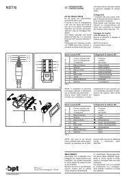
Belegung der Klemmleisten<br />
(Abb. 1)<br />
Klemmleiste G<br />
Netzversorgung<br />
Klemmleiste B<br />
0 Netzversorgungs-Ausfallmeldung<br />
1 + 17,5 V Stromversorgung<br />
2 – vom <strong>VA</strong>S/100<br />
3 Videosignal<br />
4 Videosignalabschirmung<br />
5 – 17,5 V Stromversorgung<br />
6 + zum Monitor<br />
7 Anruf<br />
8 Ton zum Monitor<br />
9 Ton zur Außenstation<br />
10 Einschaltsignal Anlage<br />
11 Ablaufendes Gespräch (Schließkontakt<br />
(–) der Versorgung über<br />
Transistor, 24 V DC 50 mA max.,<br />
für die Dauer des Gesprächs).<br />
12 Befehl für die Differenzierung<br />
des Ruftones<br />
Klemmleiste C<br />
1B 0 V AC für Entfernungen bis<br />
150 m<br />
1A 0 V AC für Entfernungen bis<br />
100 m