VA/100.02 2401-3166 12.03 - TECH FASS sro
VA/100.02 2401-3166 12.03 - TECH FASS sro
VA/100.02 2401-3166 12.03 - TECH FASS sro

Create successful ePaper yourself
Turn your PDF publications into a flip-book with our unique Google optimized e-Paper software.
con l’operatore situato davanti al<br />
monitor, che l’area di ripresa sia<br />
soddisfacente. In caso contrario<br />
modificare l’inclinazione dell’unità<br />
di ripresa (dove è possibile).<br />
7.Se l’impianto è costituito da più<br />
monitor, premere ad uno ad uno<br />
sulla targa esterna i relativi pulsanti<br />
di chiamata ed accertarsi che i<br />
monitor entrino in funzione.<br />
8.Rimettere la placca frontale.<br />
NOTA. Se l’impianto è costituito da<br />
più posti esterni, si procederà per<br />
ognuno come precedentemente<br />
descritto.<br />
MONITOR<br />
1.Accertarsi che, alla chiamata dal<br />
posto esterno, il monitor si accenda<br />
e regolare la luminosità fino ad<br />
avere un’immagine ottimale.<br />
Regolare, se necessario, il volume<br />
della nota di chiamata tramite l’apposito<br />
potenziometro.<br />
2.Verificare il funzionamento dell’audio<br />
con l’aiuto dell’operatore<br />
situato davanti al posto esterno.<br />
3.Controllare che il tempo di<br />
accensione del monitor sia di 45 s<br />
circa. Tale verifica va effettuata<br />
senza sollevare la cornetta o, negli<br />
apparecchi a viva-voce, senza<br />
azionare il pulsante audio.<br />
Se si desidera variarlo (da 15 a 60<br />
s), agire sull’apposito potenziometro<br />
situato nella centralina di controllo<br />
<strong>VA</strong>/100.<br />
4.Controllare il funzionamento dei<br />
seguenti servizi:<br />
Luce scale<br />
Premendo questo pulsante (se<br />
l’impianto è predisposto e nessuno<br />
altro monitor è in funzione) si<br />
dovranno inserire le luci di illuminazione<br />
(scale, ingresso, giardino,<br />
ecc).<br />
Inserimento del posto<br />
esterno<br />
Premendo questo pulsante (se<br />
nessun altro monitor è in funzione)<br />
si inserirà il posto esterno n. 1.<br />
Inserimento di ulteriori<br />
posti esterni o unità di ripresa supplementari<br />
Premendo nuovamente il pulsante<br />
di inserimento-selezione del posto<br />
esterno, si inserirà il posto esterno<br />
n.2 o le unità di ripresa supplementari,<br />
e così via, fino all’ultimo<br />
posto esterno (max. 10).<br />
Apriporta<br />
Premendo questo pulsante (se<br />
nessun altro monitor è in funzione)<br />
si eccita l’apriporta.<br />
1÷16 Intercomunicazione<br />
Premendo i pulsanti di chiamata<br />
per il servizio di intercomunicazione<br />
da ciascun monitor, controllare<br />
la corrispondenza del numero d’identificazione<br />
assegnato e la funzionalità<br />
dell’audio.<br />
NOTA. Se l’impianto è composto<br />
da più monitor, ripetere le operazioni<br />
sopra elencate per ogni apparecchio.<br />
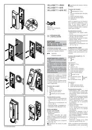
GB INSTALLATION<br />
INSTRUCTIONS<br />
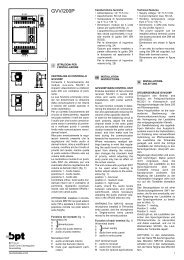
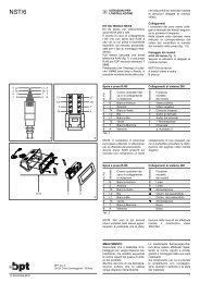
MAIN CONTROL UNIT <strong>VA</strong>/<strong>100.02</strong><br />
It is made up of a transformer<br />
which supplies the system components<br />
with alternating current and a<br />
mother card into which two other<br />
cards, controlling the system functions,<br />
are inserted.<br />
The AC outputs feeding the system<br />
components are:<br />
24 V AC - 1 A: subject illumination.<br />
This output supplies the subject<br />
illumination lamps (MVTC/100<br />
camera module and panels VZ<br />
series).<br />
18 V AC - 1 A: call button illumination.<br />
This output supplies 10 lamps<br />
(24 V, 3 W), i.e. a total of 20 call<br />
buttons on VZ entry panels, while<br />
the MC modules are supplied by<br />
the <strong>VA</strong>S/100.20 power supplier<br />
(17.5 V DC).<br />
12 V AC - 1A: door lock release<br />
solenoid. This output supplies the<br />
door release solenoid when the<br />
door lock release button on monitor<br />
is pressed.<br />
System components connections<br />
It is expected to require 3 terminals<br />
on terminal block C of <strong>VA</strong>/100, figure<br />
1, which are connected to the<br />
AC components common to compensate<br />
the distance between the<br />
<strong>VA</strong>/100 main control unit and the<br />
entry panel.<br />
For system with more entry panels<br />
installed at different distances from<br />
the power supplier group, connect<br />
each AC entry panel components<br />
common - block D terminal 1 -<br />
directly to block C terminal 1, 1A or<br />
1B of <strong>VA</strong>/100.<br />
See exemples on figure 6.<br />
Description of electronic circuit<br />
The electronic circuits which control<br />
the system are divided into 2<br />
cards which may be removed for<br />
easy maintenance. The cards have<br />
coupling guides making it impossible<br />
to mount them incorrectly.<br />
Fuctions of card 1<br />
• System activation timer. The time<br />
is adjustable from 15 to 60 s<br />
approximately by turning the<br />
potentiometer accessible through<br />
slot B, figure 2. This time interval is<br />
increased to a maximum of 3 min if<br />
the handset is lifted. Time is reduced<br />
to about 15 s when terminal 0<br />
of block B is connected to terminal<br />
5 (–) of block B.<br />
This connection can also be made<br />
by means of a switch device controlled<br />
by the power backup battery.<br />
The <strong>VA</strong>/100 can be kept in<br />
continuous operation mode if terminal<br />
10 of block B is connected to<br />
a positive voltage between 10 ÷<br />
17.5 V. This in the instance monitor<br />
and camera are required to be<br />
operating at all times.<br />
• System activation from the entry<br />
panel.<br />
• System activation from the monitor.<br />
• Amplification of monitor audio<br />
signal.<br />
•Turning off any live monitor when<br />
another user is called.<br />
• Call note timer. The time is adjustable<br />
from 1 to 12 s approximately<br />
by turning the potentiometer<br />
accessible through slot A, figure 2.<br />
The call note stops when the handset<br />
is lifted or if one of the pushbuttons<br />
is pressed.<br />
This features is only operating in<br />
system using receivers version 01<br />
and successive versions or monitor<br />
VMF/106.<br />
Functions of card 2<br />
•Turns off the system when pressing<br />
the door lock button if dipswitch<br />
2 in position .<br />
With dip-switch 2 in position the<br />
system is turned off automatically<br />
by the timer.<br />
The dip-switch is accessible through<br />
slot C, figure 2.<br />
NOTE. Make sure all receivers<br />
have dip-switch 4 in the OFF position.<br />
• Stabilization of the 15 V DC supply<br />
voltage (card 1 and 2).<br />
• Amplification of the entry panel<br />
audio signal.<br />
• Door lock release activation<br />
timer.<br />
This circuits limits the time the voltage<br />
output is applied to door<br />
release solenoid (adjustable from 1<br />
to 15 s by turning the potentiometer<br />
accessible from slot D, figure 2)<br />
even if the door lock release button<br />
is kept depressed (dip-switch 1 to<br />
position , figure 2).<br />
It is possible to turn off this facility<br />
when continuous output, for the<br />
time the door lock release button<br />
on monitor is pressed, to door<br />
release solenoid is required by setting<br />
the dip-switch 1 to position ,<br />
figure 2.<br />
The dip-switch is accessible through<br />
slot C, figure 2.<br />
• Activation auxiliary service.<br />
• Generation of electronic two-tone<br />
call. The pitch of the call tone can<br />
be changed by connecting terminal<br />
12 of block B to a positive voltage<br />
(10 ÷ 17.5 V).<br />
If the system has more entry<br />
panels it is possible to assign a different<br />
call tone pitch to one of them<br />
to identify when this is calling.<br />
For this purpose connect terminal<br />
12 of block B to VSI/110 terminal<br />
block L of relevant entry panel<br />
(figure 5).<br />
• Signal detecting when any handset<br />
is off the cradle or if one of the<br />
push-buttons is pressed.<br />
For the connection see diagram SE<br />
7012 on page 16.<br />
Function of each terminal, figure 1<br />
Terminal block G<br />
mains<br />
Terminal block B<br />
0 signal detecting mains failure<br />
1 + 17.5 V supply voltage<br />
2 – from <strong>VA</strong>S/100<br />
3 video signal<br />
4 video signal shield<br />
5 – 17.5 V supply voltage<br />
6 + to monitor<br />
7 call<br />
8 audio signal to monitor<br />
9 audio signal to entry panel<br />
10 signal activating system<br />
11 conversation in progress (contact<br />
closed at the negative<br />
power supply by a transistor,<br />
24 V DC 50 mA max., for the<br />
duration of the conversation)<br />
12 facility for altering call tone<br />
pitch<br />
Terminal block C<br />
1B AC common for distances up to<br />
150 m<br />
1A AC common for distances up to<br />
100 m<br />
1 AC common for distances up<br />
to 50 m<br />
2 24 V AC for subject illumination<br />
lamps (MVTC/100 camera and<br />
entry panels VZ series).<br />
3 18 V AC for call buttons lamps<br />
or modules MC<br />
4 12 V AC for additional door<br />
lock release<br />
5 – 17.5 V supply voltage<br />
6 + to entry panel<br />
7 call no. 1<br />
8 call button common<br />
9 video signal shield<br />
10 video signal<br />
11 audio signal to monitor<br />
12 audio signal to entry panel<br />
13 door lock release, 12 V AC<br />
14 entry panel enabling<br />
Stair light output<br />
17 common<br />
18 relay contact normally closed<br />
19 relay contact normally open<br />
Technical features<br />
• Supply voltage: 230 V 50/60 Hz.<br />
The transformer primary is protected<br />
by the slow fuse F1, T 500<br />
mA.<br />
• Power absorption: 50 <strong>VA</strong>.<br />
• DC current demand: 40 mA<br />
(max. 100 mA when relays energized).<br />
• Secondary output voltages for<br />
system components:<br />
24 V AC 1A protected by the<br />
slow fuse F2, T 1.25 A.<br />
18 V AC 1A protected by the<br />
slow fuse F3, T 1.25 A.<br />
12 V AC 1 A protected by the<br />
slow fuse F4, T 1.25 A.<br />
• Max. door release current<br />
demand: 1 A at 12 V AC (max.<br />
load to relay conctact: 5 A at 24 V<br />
AC).<br />
• Max. current demand to auxiliary<br />
service relay: 5 A at 250 V AC (2<br />
A if load is inductive).<br />
• Enables up to 30 receivers to be<br />
connected to same call button.<br />
IMPORTANT. However additional<br />
<strong>VA</strong>S/100 power supplier must be<br />
added for every additional 2 (3)<br />
monitors connected to the same<br />
call line.<br />
•Working temperature range: from<br />
0 °C to +35 °C.<br />
• Dimensions: 12 DIN units, high<br />
profile module, figure 4.<br />
The equipment can be installed<br />
without terminal covers into boxes<br />
provided with DIN rail (EN 50022).<br />
3