VMF/100.01 2401-7655 04.2003 - TECH FASS sro
VMF/100.01 2401-7655 04.2003 - TECH FASS sro
VMF/100.01 2401-7655 04.2003 - TECH FASS sro

You also want an ePaper? Increase the reach of your titles
YUMPU automatically turns print PDFs into web optimized ePapers that Google loves.
2<br />
ON<br />
OFF<br />
2<br />
P1<br />
3<br />
F1<br />
9 87654321<br />
2<br />
10<br />
11<br />
12<br />
13<br />
14<br />
15<br />
1<br />
4<br />
5<br />
4<br />
6<br />
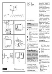
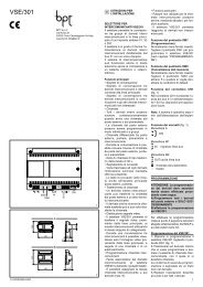
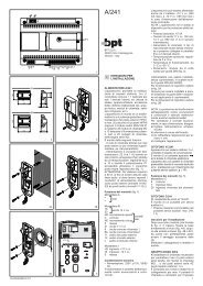
Spostare il dispositivo di bloccaggio come indicato<br />
in fig. 2A. Sfilare il supporto in acciaio dal monitor e<br />
fissarlo, ad un’altezza adatta all’utente, mediante<br />
tasselli e viti in dotazione.<br />
Rispettare l’indicazione ALTO e fare in modo che<br />
l’uscita dei cavi dalla parete coincida con l’apposito<br />
passaggio del supporto (fig. 3).<br />
Svitare le due viti di fissaggio e togliere la parte<br />
sinistra del mobile (fig. 4). Passare i conduttori<br />
attraverso la feritoia sul fondo del monitor, posizionare<br />
il monitor nel supporto da parete ed innestarlo<br />
al supporto stesso con un movimento verso il basso<br />
(fig. 5).<br />
Per evitare cadute dal monitor a causa di urti accidentali,<br />
bloccare il monitor stesso al supporto da<br />
parete spostando verso destra (fig. 2B) il dispositivo<br />
di bloccaggio.<br />
Procedere nella maniera opposta in caso di smontaggio<br />
del monitor.<br />
Effettuare i collegamenti e rimettere la parte sinistra<br />
del mobile fissandola con le due viti.<br />
GB<br />
INSTRUCTIONS FOR USE<br />
AND INSTALLATION<br />
WARNING FOR THE INSTALLER<br />
These instructions should be attached to the<br />
receiver.<br />
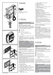
<strong>VMF</strong>/<strong>100.01</strong> FLAT MONITOR WITH HANDSET<br />
It is equipped with the following controls and warnings,<br />
figure 1:<br />
Thumb-wheel D to switch the monitor<br />
ON/OFF and for the brightness control.<br />
Button to bring the monitor live and manual<br />
sequencing of any additional panel/camera.<br />
Button to turn on stairs light.<br />
Door lock release button.<br />
• Aux 1 - Button for auxiliary services as<br />
required.<br />
•<br />
Aux 2 - Button for auxiliary services as<br />
required.<br />
LED 1 Green LED can be used to indicate an<br />
external function.<br />
LED 2 Yellow LED can be used to indicate an<br />
external function.<br />
LED 3 Red LED can be used to indicate an external<br />
function.<br />
Switches Aux 1 and Aux 2 are normally open, when<br />
actuated the contacts close on –0V DC. Max. current<br />
demand 100mA at 24V.<br />
To activate LED 1 and LED 2 line 13 and 14 should<br />
be connected via an external switch device which is<br />
common to terminal 5 of the system, 0V DC.<br />
The monitor is protected by the slow blow fuse F1 - T<br />
500 mA - mounted on monitor’s printed card, figures 6.<br />
(Fuse: F = fast, T = slow).<br />
WARNINGS FOR THE USER<br />
- Please do not open or tamper the device (high<br />
voltage!).<br />
- Please avoid knocking or bumping the apparatus<br />
as it could result in the breakage of the picture tube<br />
and the consequent projection of glass fragments.<br />
- In the case of breakdown or modification of the<br />
apparatus of the system (such as power supplier …)<br />
please contact a specialized maintenance service.<br />
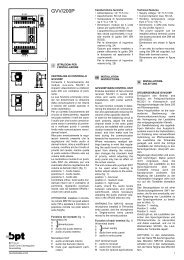
Three special monitor operation modes can be<br />
chosen by means of jumpers 2, 3 and 4 located<br />
on monitor’s printed card, figure 6.<br />
NOTE. The ON position is achieved by inserting the<br />
jumper across 2 pins to assure alectric connection.<br />
The jumper must be inserted on 1 pin only when OFF<br />
position is required. See detail on top of fig. 6.<br />
• Monitor in constant mode<br />
For use only in single house installations as close<br />
circuit television system with camera always powered<br />
and separated from entry panel.<br />
<strong>VMF</strong>/100 is supplied from the factory with jumper 2<br />
in the OFF position.<br />
The constant mode is achieved with jumper 2 set to<br />
ON position. The monitor can only be switched off<br />
by thumbwheel switch D, figure 1.<br />
• Activation of more monitors by the same call<br />
Jumper 3 is normally kept in the ON position, this<br />
way the call line loop is closed. If more monitors<br />
must be activated by the same call, leave only one<br />
with the jumper 3 in the ON position, all other monitors<br />
must have the jumper 3 in the OFF position.<br />
• Monitor/system turned off on door release<br />
a) Systems with VA/100 main control unit<br />
Jumper 4 is normally kept in the OFF position. In<br />
this position the monitor is turned off automatically<br />
by the system timer.<br />
Whit Jumper 4 in the ON position the monitor is turned<br />
off by pressing the door lock release button.<br />
b) Systems with VA/<strong>100.01</strong> main control unit<br />
Jumper 4 must be in the OFF position<br />
Use dip-switch 2 of the VA/<strong>100.01</strong> main control unit<br />
to turn off the monitor.<br />
Call tone<br />
It is possible to regulate the call tone level from the<br />
entry panel by adjusting the trimmer P1, figure 6.<br />
System using main control unit VA/<strong>100.01</strong> has a<br />
timed call feature.<br />
The call stops either when the handset is lifted or<br />
when any button is pressed.<br />
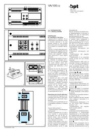
Function of each terminal, figure 6<br />
1 video signal<br />
( 1 )<br />
2 video signal shield<br />
3 video signal<br />
4 video signal shield<br />
5 – 14÷17.5 V<br />
6 + supply voltage to monitor<br />
7 call<br />
8 audio to monitor<br />
9 audio to entry panel<br />
10 11.5 V DC voltage output ( 2 )<br />
or input to turn on monitor when connected to<br />
positive voltage system (+15÷17.5 V DC)<br />
11 Aux 1<br />
12 Aux 2<br />
13 LED 1 (green)<br />
14 LED 2 (yellow)<br />
15 LED 3 (red)<br />
( 1 ) 75 Ω closing resistance if video line stops here<br />
( 2 ) This voltage output is available for the time the<br />
monitor is operating. Max. current demand should<br />
not exceed 50 mA.<br />
NOTE. Connect wires to terminals in accordance to<br />
VM/100 diagrams.<br />
Technical features<br />
• Picture screen: 4” (10 cm).<br />
• Supply voltage: 14÷17.5 V DC.<br />
• Max. current demand: 400 mA (5 mA quiescent).<br />
• Current demand per LED: 7 mA.<br />
• Bandwidth response at -3 dB: 6 MHz.<br />
•Video input: 1 Vpp (from 0,7 Vpp to 2 Vpp).<br />
•Video input impedance: >15 KΩ.<br />
• Call signal: electronic dual tone note, the call<br />
volume can be regulated.<br />
• Aux 1 and Aux 2: normally open switch, when<br />
actuated the contact closes to 0 V DC.<br />
• Current demand should not exceed 100 mA at 24 V.<br />
•Working temperature range: from 0 °C to +35 °C.<br />
• Dimensions: 195 x 230 x 72 mm.<br />
INSTALLATION<br />
WARNING. It is recommended to install the<br />
monitor in a dry place.<br />
Slide the locking latch as shown in figure 2A. Slide<br />
the steel frame out, and fix it on the wall at a suitable<br />
height by using the screws and retainers included<br />
in the pack.<br />
Please, pay attention to place the frame with the<br />
indication TOP in upper position, and make the holl<br />
figure 3, to coincide with the cable junction box.