You also want an ePaper? Increase the reach of your titles
YUMPU automatically turns print PDFs into web optimized ePapers that Google loves.
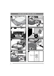
6. If the air filter must be replaced, pull this out as<br />
well.<br />
7. Reassemble all parts in the reverse order.<br />
8. Reset the filter indicator if it has tripped. See<br />
“3.5.7”.<br />
6.14 Lubrication<br />
All lubrication points according to the table below<br />
must be lubricated after every 50 operating hours<br />
as well as after each clean.<br />
Use a grease gun, filled with universal grease.<br />
Pump until grease protrudes. The lubrication<br />
points are shown in fig. 28-30.<br />
Note the belts when lubricating. Belts<br />
must not come into contact with oil or<br />
grease.<br />
Object Lubrication nipples /<br />
action<br />
Figure<br />
Tension arm, 1 lubrication nipple.<br />
pump belt<br />
30:A<br />
Lifting fork,<br />
turning<br />
1 lubrication nipple 30:B<br />
Lifting fork,<br />
up-down<br />
2 lubrication nipples 30:G, H<br />
Lifting cylinder<br />
2 lubrication nipples 30:C, E<br />
Control cylin- 2 lubrication nipples<br />
der<br />
30:D, F<br />
Pivot point 3 lubrication nipples 30:J<br />
Tension arm, 1 lubrication nipple. 28<br />
auxiliaries<br />
belt<br />
Be careful with the<br />
belts. Belts must not<br />
(Only 20B come into contact with<br />
and 26B) grease.<br />
Tension arm, 1 lubrication nipple. 30:K<br />
rear imple- Be careful with the<br />
ment belt belts. Belts must not<br />
(Only 20B come into contact with<br />
and 26B) grease.<br />
Throttle cable Lubricate the cable ends<br />
using an oil can at the<br />
same time as activating<br />
the respective control.<br />
Preferably carried out by<br />
two people.<br />
29<br />
6.15 Valves<br />
Valve adjustment and grinding should be carried<br />
out by authorised workshops.<br />
ENGLISH GB<br />
6.16 Fuses<br />
If any of the following faults occur, replace the relevant<br />
fuse. The fuses are under the cover in fig. 25.<br />
Remove the cover by removing the 5 screws.<br />
Check and replace blown fuses. If the fault persists,<br />
contact an authorised workshop.<br />
Fuse<br />
Fault<br />
Location Rating<br />
Indicator lamps, buzzer,<br />
hold valve transport position<br />
25:A 10 A<br />
Cutting height, sand<br />
spreader, rear rake, headlight<br />
25:B 20 A<br />
Cruise control, alternator 25:C 10 A<br />
Electric socket on panel 25:D 10 A<br />
Shut off pull 25:E 30 A<br />
PTO, warning lamp parking,<br />
safety relay<br />
25:F 10 A<br />
Spare 25:G<br />
Main fuse 25:H 40 A<br />
GGP reserves the right to make alterations to the<br />
product wit<br />
87