Create successful ePaper yourself
Turn your PDF publications into a flip-book with our unique Google optimized e-Paper software.
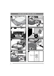
3.4.4 Hydraulic control (1:R1)<br />
This control is used to control certain functions depending<br />
on the attached implement.<br />
The control only works when the engine is running<br />
and the implement’s hydraulic hoses for the intended<br />
function are connected as follows:<br />
Implement at the front via the hydraulic outputs<br />
(1:R).<br />
Implement at the rear via the hydraulic output<br />
(5:Re).<br />
Both hydraulic outputs above are connected in parallel.<br />
3.4.5 Emergency brake / Parking brake<br />
(1:P)<br />
The pedal must never be depressed<br />
during operation. Risk of overheating<br />
in power transmission and brake.<br />
The pedal has the following<br />
functions:<br />
During operation. Emergency brake.<br />
When stopping. Parking brake.<br />
3.4.6 Inhibitor, parking brake (1:Q)<br />
The inhibitor locks the pedal (1:P) in the<br />
depressed position. The function is used to<br />
lock the machine on slopes, when transporting,<br />
etc. when the engine is not running.<br />
Locking:<br />
1. Depress the pedal (1:P) fully.<br />
2. Turn the inhibitor forwards.<br />
3. Release the pedal.<br />
Releasing:<br />
1. Depress the pedal (1:P) fully.<br />
2. Turn the inhibitor backwards.<br />
3. Release the pedal.<br />
3.4.7 Drive / service brake (1:N)<br />
If the machine does not brake as<br />
expected when the pedal is released, the<br />
left pedal (1:P) should be used as an<br />
emergency brake.<br />
The pedal determines the gear ratio between the<br />
engine and the driven wheels (= speed). The service<br />
brake is activated when the pedal is released.<br />
1. Press the pedal forwards<br />
and the machine starts to<br />
move forwards.<br />
2. No load on the pedal<br />
– the machine is stationary.<br />
3. Pedal moved backwards –<br />
the machine reverses.<br />
ENGLISH GB<br />
4. Pressure relieved from the pedal – the machine<br />
brakes.<br />
The maximum speed can be reduced to optimal<br />
working speed with the inhibitor (1:E).<br />
3.4.8 Speed inhibitor (1:E)<br />
The machine’s speed range can be limited by stopping<br />
the drive-service brake pedal (1, 1:N) with the<br />
speed inhibitor (1:E).<br />
With the speed inhibitor activated an optimal maximum<br />
speed is achieved during work with the implement.<br />
Locking:<br />
Turn the speed control forwards.<br />
Resetting:<br />
Turn the speed control back.<br />
3.4.9 Steering wheel (1:T)<br />
Do not adjust the steering wheel during<br />
operation.<br />
The steering wheel can be raised and lowered and<br />
set at different angles smoothly.<br />
Raising and lowering:<br />
Undo the knob (1:S) on the steering column and<br />
raise or lower the steering wheel to the desired position.<br />
Tighten.<br />
Angle adjustment:<br />
Release the control (1:C) on the side of the steering<br />
column and set the steering wheel to the desired<br />
angle. Tighten the control.<br />
3.4.10Throttle control (1:X).<br />
Control for setting the engine’s revs.<br />
Full throttle - when the machine is in operation,<br />
full throttle should always be<br />
used.<br />
Idling.<br />
3.4.11 Ignition lock (1:V)<br />
The ignition lock is used for starting and stopping<br />
the engine.<br />
Four positions:<br />
Preheat position: The cylinders are heated<br />
to facilitate starting. Hold in this position<br />
as below at lower temperatures before<br />
starting the engine.<br />
20B, 26B, 26H: max 5 seconds<br />
32H: max 15 seconds<br />
Stop position: The engine is stopped. The<br />
key can be removed.<br />
Operating position: Bypassed at start-up<br />
and used when the engine is running.<br />
77