Spetzler® Lumbar Peritoneal Shunt Systems
Spetzler® Lumbar Peritoneal Shunt Systems
Spetzler® Lumbar Peritoneal Shunt Systems

Create successful ePaper yourself
Turn your PDF publications into a flip-book with our unique Google optimized e-Paper software.
Spetzler ® <strong>Lumbar</strong> <strong>Peritoneal</strong><br />
<strong>Shunt</strong> <strong>Systems</strong><br />
Sterile For Single Use Only<br />
Description<br />
The Spetzler ® <strong>Lumbar</strong> <strong>Peritoneal</strong><br />
<strong>Shunt</strong> <strong>Systems</strong> are designed to shunt<br />
cerebrospinal fluid (CSF) from the<br />
lumbar subarachnoid space to the<br />
peritoneum. Due to the small diameter<br />
of the catheter tubing, shunting may<br />
be accomplished by percutaneous<br />
techniques. The lumbar catheter is<br />
inserted into the lumbar subarachnoid<br />
space through a 3 1 ¼2-inch, 14-gauge<br />
Touhy spinal needle with a Huber tip.<br />
A catheter passer and peritoneal trocar<br />
may be used to bring the peritoneal<br />
catheter section around the flank and<br />
into the peritoneal cavity.<br />
A variety of devices are available: a<br />
one-piece model without a reservoir;<br />
separate large or small reservoirs that<br />
contain a one-way valve, which may<br />
be used when a flushing capability is<br />
required; and a separate miter valve,<br />
available in low, medium, or high<br />
pressure, which may be used when<br />
added resistance is desired.<br />
One-Piece Model<br />
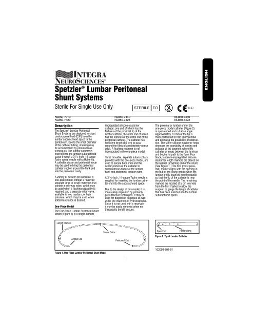
The One-Piece <strong>Lumbar</strong> <strong>Peritoneal</strong> <strong>Shunt</strong><br />
Model (Figure 1) is a single, barium-<br />
Length Markers<br />
<strong>Lumbar</strong> End<br />
Figure 1. One-Piece <strong>Lumbar</strong> <strong>Peritoneal</strong> <strong>Shunt</strong> Model<br />
impregnated silicone elastomer<br />
catheter, one end of which has the<br />
features of the proximal tip of the<br />
lumbar catheter, the other end of which<br />
has the features of the distal end of the<br />
peritoneal catheter. The catheter has<br />
sufficient length (80 cm) to pass<br />
around the flank of a moderately obese<br />
adult. A flushing reservoir is not<br />
incorporated in the one-piece model.<br />
Three movable, separate suture collars,<br />
provided with the one-piece model, are<br />
used to secure both ends and the<br />
center portion of the catheter to<br />
subcutaneous tissue at the lumbar,<br />
flank and abdominal incision sites.<br />
A 31¼2-inch, 14-gauge Touhy needle is<br />
supplied for inserting the lumbar catheter<br />
end into the subarachnoid space.<br />
Due to the design of this model, it is<br />
more easily implanted by primarily<br />
percutaneous techniques. It may be<br />
used for diagnostic purposes as well<br />
as for the treatment of hydrocephalus.<br />
Since it is not used with a reservoir,<br />
it may be easily removed when no<br />
therapeutic benefit ensues.<br />
Suture Collar<br />
<strong>Peritoneal</strong> End<br />
1<br />
STERILE EO 0123 2<br />
NL850-7210 NL850-7440 NL850-7460<br />
NL850-7420 NL850-7421 NL850-7422<br />
The proximal or lumbar end of the<br />
one-piece model catheter (Figure 2)<br />
is open-ended and cut at an angle.<br />
Approximately 18 mm of the tip is<br />
multi-perforated to help improve flow<br />
and decrease the possibility of obstruction.<br />
The stiffer silicone elastomer helps<br />
decrease the possibility of kinking and<br />
collapse at the segment where the<br />
catheter emerges between the laminae<br />
and begins its path to the flank. Four<br />
black, tantalum-impregnated, silicone<br />
elastomer length markers are placed on<br />
the lumbar (proximal) end of the shunt.<br />
(See Figure 1.) The first (most proximal)<br />
marker aligns with the opening in<br />
the hub of the Touhy needle when the<br />
lumbar end is inserted into the needle<br />
so that the tip of the catheter is near<br />
the point of the needle. The remaining<br />
markers are located at 5 cm intervals<br />
from the first marker to allow the<br />
surgeon to gauge the length of catheter<br />
that has been inserted into the lumbar<br />
subarachnoid space.<br />
Open End<br />
Figure 2. Tip of <strong>Lumbar</strong> Catheter<br />
102099-701-01<br />
Perforations<br />
ENGLISH<br />
FRANÇAIS<br />
DEUTSCH<br />
ITALIANO<br />
ESPAÑOL
Slit Valve<br />
Tantalum-<br />
Impregnated Tip<br />
Figure 3. Tip of <strong>Peritoneal</strong> Catheter<br />
Connector<br />
<strong>Lumbar</strong> Catheter <strong>Peritoneal</strong> Catheter<br />
Figure 4. Splicing a Cut One-Piece <strong>Shunt</strong><br />
Without a Reservoir<br />
The distal or peritoneal end of the<br />
one-piece model catheter (Figure 3)<br />
incorporates a radiopaque, tantalumimpregnated<br />
silicone elastomer tip. Two<br />
through-slits (making four slits in the<br />
catheter wall), spaced 90° radially and<br />
3 mm axially, provide pressure control<br />
and resist retrograde flow and<br />
obstruction at the distal end.<br />
A separate stainless steel connector is<br />
supplied with the one-piece model. In<br />
case it is necessary for the surgeon to<br />
cut the catheter, the cut ends can be<br />
joined with the connector. (Figure 4.)<br />
Length Markers<br />
Suture Collar<br />
Ligatures (2)<br />
Connectors<br />
<strong>Lumbar</strong> Catheter<br />
Figure 5. Three-Piece <strong>Lumbar</strong> <strong>Peritoneal</strong> <strong>Shunt</strong>ing System<br />
Reservoir<br />
A Three-Piece <strong>Lumbar</strong> <strong>Peritoneal</strong> <strong>Shunt</strong><br />
System (Figure 5) may be devised by<br />
the user by ordering a reservoir and the<br />
one-piece shunt model and cutting the<br />
one-piece shunt at its midpoint. Using<br />
the two stainless steel connectors<br />
supplied with the reservoir, the lumbar<br />
and peritoneal ends of the shunt may<br />
be assembled onto a reservoir and<br />
ligated in place. (See Instructions<br />
For Use).<br />
Both the large and small reservoirs<br />
include a one-way flow miter valve in<br />
the reservoir-dome-inlet port. The miter<br />
valve resists retrograde flow of fluid to<br />
the lumbar subarachnoid space. The<br />
capacity of the large reservoir is greater<br />
than that of other Integra NeuroCare<br />
LLC reservoirs. The large reservoir<br />
improves palpability and facilitates the<br />
use of the reservoir for flushing the<br />
peritoneal catheter, for injection of a<br />
radionuclide to evaluate shunt function,<br />
or for sampling CSF. The small<br />
reservoir, however, may be preferable<br />
for use in patients with thin skin (e.g.,<br />
slender patients) or for cosmetic<br />
purposes. Fluid-flow direction is<br />
indicated by an arrow molded into the<br />
reservoir dome top. (Figure 6).<br />
The reservoir (Figure 6) is connected<br />
to the catheters by assembling the<br />
supplied stainless steel connectors into<br />
the lumbar and peritoneal ends of the<br />
cut one-piece shunt and then slipping<br />
the assembly into the tubes on the<br />
reservoir. A ligature is placed around<br />
each connector and tube (four total)<br />
to secure and seal the connectors.<br />
Ligatures should not be so tight as<br />
to cut through the tubing. The base<br />
of the reservoir may be sutured to the<br />
subcutaneous tissue.<br />
Ligatures<br />
Flushing Reservoir<br />
Suture Through<br />
Base Edge<br />
<strong>Peritoneal</strong> Catheter<br />
2<br />
In-Line Valve<br />
Additional resistance to flow may be<br />
obtained by the placement of a small<br />
cylindrically housed miter valve at any<br />
point along the <strong>Lumbar</strong> <strong>Peritoneal</strong><br />
<strong>Shunt</strong>. This valve is available in low,<br />
medium, and high pressure ranges<br />
and contains integral stainless steel<br />
connectors for easy insertion at the<br />
time of initial shunt placement or<br />
revision. Fluid flow direction is<br />
indicated by a radiopaque arrow on the<br />
valve housing. The differential pressure<br />
range is identified by a tantalumimpregnated<br />
silicone elastomer dot<br />
code on the valve housing. Refer to<br />
valve performance chart.<br />
Pressure Values<br />
Since the <strong>Lumbar</strong> <strong>Peritoneal</strong> <strong>Shunt</strong><br />
System is implanted at the level of<br />
the lumbar region of the spine, it is<br />
designed to provide relatively high<br />
resistance to cerebrospinal fluid flow.<br />
Pressure control is achieved by the<br />
combined action of the double-slit valve<br />
at the peritoneal end and the small<br />
internal diameter (.7 mm or .028”)<br />
of the catheter tubing.<br />
Catheter performance characteristics<br />
are reported in accordance with the<br />
shunt performance test method<br />
contained in the American Society for<br />
Testing and Materials F647-79, “Standard<br />
Practice for Evaluating and Specifying<br />
Implantable <strong>Shunt</strong> Assemblies for<br />
Neurosurgical Application.”<br />
<strong>Lumbar</strong> End<br />
Inlet Tube<br />
Miter Valve<br />
Suture Through<br />
Base Edge<br />
Outlet Tube<br />
Molded Arrow<br />
Ligatures (4)<br />
Connector<br />
<strong>Peritoneal</strong> End<br />
Figure 6. Reservoir, Showing installation of<br />
<strong>Lumbar</strong> and <strong>Peritoneal</strong> <strong>Shunt</strong> Ends<br />
ENGLISH<br />
FRANÇAIS<br />
DEUTSCH<br />
ITALIANO<br />
ESPAÑOL
Indications<br />
Percutaneous lumbar peritoneal<br />
shunting may be utilized in the<br />
treatment of communicating<br />
hydrocephalus. It is designed to shunt<br />
CSF from the lumbar subarachnoid<br />
space to the peritoneal cavity.<br />
The shunt may be used for diagnosis,<br />
evaluation or treatment of normal pressure<br />
communicating hydrocephalus.<br />
A percutaneous lumbar peritoneal shunt<br />
is also useful in the management of<br />
persistent cerebrospinal fluid fistulas,<br />
bulging cranial and suboccipital<br />
decompressions and in transient CSF<br />
absorption defects, e.g., postmeningitic<br />
or post-hemorrhagic<br />
hydrocephalus.<br />
The In-Line Valve, available as a<br />
separate component of the system, is<br />
indicated for use where added resistance<br />
is desired to alleviate symptoms<br />
of low pressure in the small percentage<br />
of patients who, after normal drainage<br />
and in the normal course of treatment,<br />
develop such symptoms.<br />
Contraindications<br />
<strong>Lumbar</strong> <strong>Peritoneal</strong> <strong>Shunt</strong>ing <strong>Systems</strong><br />
should not be used for noncommunicating<br />
hydrocephalus.<br />
<strong>Lumbar</strong> <strong>Peritoneal</strong> <strong>Shunt</strong>ing <strong>Systems</strong><br />
should not be used in the presence of<br />
known or suspected meningitis, ventriculitis,<br />
skin infections, bacteremia,<br />
septicemia or peritonitis. It is advisable<br />
to avoid shunting procedures if infection<br />
is present anywhere in the body.<br />
<strong>Lumbar</strong> peritoneal shunting systems<br />
are contraindicated in cases of spinal<br />
abnormalities that would prevent free<br />
insertion of the lumbar catheter.<br />
<strong>Lumbar</strong> peritoneal shunts are contraindicated<br />
in infants where the lower end<br />
of the spinal cord has not yet migrated<br />
to its cephalad L1-2 position.<br />
In view of the marked narrowing of the<br />
lumbosacral canal in achondroplastic<br />
patients, a lumbar shunt in the<br />
subarachnoid space is contraindicated.<br />
The trocar method of peritoneal<br />
catheter introduction is contraindicated<br />
if there have been<br />
previous abdominal operations<br />
or if excessive obesity exists.<br />
Instructions For Use<br />
The introduction of a shunting system<br />
may be accomplished through a variety<br />
of surgical techniques; therefore, the<br />
surgeon is best advised to use the<br />
method which his/her own practice and<br />
training dictate to be best for the patient.<br />
Instructions For <strong>Shunt</strong> Patency Test<br />
The components of each shunt model<br />
should be tested for patency prior to<br />
implantation. The following procedures<br />
are recommended:<br />
One-Piece Model and Assembled<br />
Three-Piece Model<br />
Using aseptic technique, insert a<br />
20-gauge, blunt syringe needle into the<br />
most distal of the side-inlet holes on<br />
the proximal, lumbar end. Gently flush<br />
the lumen of the entire shunt with 5 to<br />
10 cc. of sterile, isotonic solution.<br />
Fluid should flow freely from the slit<br />
valves in the distal, peritoneal end (four<br />
slits in the tubing wall). If all four slits<br />
do not allow the fluid to flow freely,<br />
gently roll the slit valve area between<br />
the thumb and forefinger to open the<br />
slits. Repeat the flushing procedure.<br />
Note: The valve slits are coated with<br />
graphite to minimize adherence during<br />
storage and should not be flushed with<br />
any solution before patency is tested<br />
immediately prior to implantation.<br />
In-Line Valve<br />
Valve Patency and<br />
Closing Pressure Test<br />
1. Connect the enclosed length of<br />
sterile tubing to the inlet tube of the<br />
valve and elevate the tubing above the<br />
valve. No tubing should be connected<br />
to the outlet connector.<br />
3<br />
2. Orient the valve horizontally on the<br />
test table.<br />
3. Using a syringe, fill the tube to<br />
approximately 18 cm. Use sterile deaerated<br />
water to help eliminate air<br />
bubbles in tubing and valve.<br />
4. After flow through tubing and valve<br />
has been established, examine tubing<br />
and valve to insure bubbles have been<br />
eliminated. Do not flush the valve with<br />
a syringe. The amount of pressure<br />
created by syringe flushing will<br />
temporarily deform the silicone<br />
elastomer miter valve, which will cause<br />
abnormally low pressure test results.<br />
5. When the water level is within the<br />
intended pressure range (low–15 to<br />
54mm H2O, medium–55 to 94mm H2O<br />
or high–95 to 150mm H2O), a noticeable<br />
slowing of flow should occur.<br />
6. The valve closing pressure should be<br />
checked when the water level is at the<br />
lower limit of the range. The discharge<br />
from the valve outlet tube should be<br />
less than or equal to 0.15ml/min., when<br />
measured at the lower limit of the<br />
pressure range. The pressure is that<br />
recorded by measuring the distance<br />
from the base of the valve to the top<br />
of the water column in the inlet tube<br />
extension. Due to characteristics of<br />
silicone materials, some variation in<br />
pressure performance may occur.<br />
Procedural Instructions<br />
The following information relevant<br />
to the use of both models of the<br />
<strong>Lumbar</strong> <strong>Peritoneal</strong> <strong>Shunt</strong>ing System<br />
is provided by Dr. Robert Spetzler,*<br />
based on his experience in the<br />
surgical treatment of patients with<br />
communicating hydrocephalus.<br />
*Robert Spetzler, M.D.<br />
Director, Barrow Neurological Institute<br />
Chairman, Division of Neurosurgery<br />
350 West Thomas Road, Phoenix, AZ 85013<br />
ENGLISH<br />
FRANÇAIS<br />
DEUTSCH<br />
ITALIANO<br />
ESPAÑOL
Multi<br />
Perforated<br />
Tip Passed<br />
8cm<br />
Touhy Needle<br />
<strong>Lumbar</strong> Catheter<br />
Figure 7. Insertion of <strong>Lumbar</strong> Portion of<br />
One-Piece Catheter in Subarachnoid Space<br />
Push Distal Catheter End<br />
Through Tubing<br />
Subcutaneous<br />
Catheter<br />
Passer<br />
Optional Suction<br />
Catheter Tip<br />
Figure 9. Insertion of Distal End of One-<br />
Piece Catheter through Flank Incision<br />
One-Piece Model<br />
Note: See illustrations for detail of the<br />
insertion of the one-piece model. Specifics<br />
regarding the use of the threepiece<br />
model with reservoir attachment<br />
are given in the section which follows<br />
the one-piece model procedure.<br />
1. A Foley catheter should be inserted<br />
in the bladder to minimize the<br />
possibility of perforating the bladder<br />
when inserting the peritoneal catheter.<br />
2. The back, flank and abdomen are<br />
scrubbed and draped with the patient in<br />
a lateral position with both knees flexed.<br />
<strong>Lumbar</strong><br />
Catheter<br />
Suture Collar<br />
Touhy Needle<br />
<strong>Lumbar</strong> Catheter<br />
Figure 8. <strong>Lumbar</strong> Portion of One-Piece<br />
Catheter in Place<br />
Flank<br />
Incision<br />
Withdraw Subcutaneous<br />
Catheter Passer<br />
3. Make a 1-centimeter skin incision<br />
between the spinous process of L4-5<br />
or L5-S1. Temporarily elevate the head<br />
of the table 30° to increase the<br />
pressure in the lumbar subarachnoid<br />
space.<br />
4. Insert the supplied 14-gauge,<br />
31¼2-inch extra thin-wall Touhy needle<br />
into the low lumbar subarachnoid<br />
space with the bevel pointed cephalad<br />
or caudad.<br />
5. Pass the open, multi-perforated end<br />
of the one-piece catheter through the<br />
Touhy needle for a distance of 8 cm<br />
(Figure 7). Tilt the operating-room table<br />
back to the normal position.<br />
4<br />
Suture<br />
Collar<br />
Figure 10. Distal End of One-Piece Catheter<br />
in Place through Flank Incision<br />
If the catheter must be retracted<br />
and some resistance is encountered,<br />
withdraw the Touhy needle<br />
approximately 1¼2 cm, then push the<br />
catheter forward slightly to free it<br />
and then withdraw the catheter.<br />
6. Withdraw the needle over the<br />
catheter. If the CSF pressure is greater<br />
than the flow resistance of the onepiece<br />
shunt, CSF may be seen<br />
escaping from the slit valves in the<br />
distal end of the one-piece shunt.<br />
7. Place a single suture collar around<br />
the catheter in the lumbar area and<br />
suture it to the subcutaneous tissue to<br />
hold the catheter in place (Figure 8).<br />
8. Make a small incision in the flank<br />
and pass the malleable Subcutaneous<br />
Catheter Passer with the obturator in<br />
place through the flank incision, subcutaneously<br />
around to the lumbar incision.<br />
This specially designed instrument, with<br />
the obturator attached, is malleable and<br />
may be bent to facilitate this procedure.<br />
Remove the obturator and insert the<br />
distal end of the one-piece catheter into<br />
the lumbar opening of the Subcutaneous<br />
Catheter Passer.<br />
Gently push the catheter through the<br />
passer. Care must be taken to avoid<br />
damage to the catheter, as the slit<br />
valve of the peritoneal end can be<br />
deformed or torn if too much force is<br />
used. In the event the catheter cannot<br />
be easily pushed through the passer,<br />
the catheter can be pulled through by<br />
applying gentle suction to the flank end<br />
of the subcutaneous catheter passer.<br />
(The end of the catheter passer accepts<br />
standard suction tubing.) (Figure 9).<br />
Withdraw the Subcutaneous Catheter<br />
Passer over the catheter leaving the<br />
flank portion in place. Place a single<br />
suture collar around the catheter in<br />
the flank incision and suture it to the<br />
subcutaneous tissue to hold the<br />
catheter in place (Figure 10).<br />
9. Make a small skin incision two<br />
centimeters below the umbilicus in<br />
the midline through the linea alba.<br />
ENGLISH<br />
FRANÇAIS<br />
DEUTSCH<br />
ITALIANO<br />
ESPAÑOL
Push <strong>Peritoneal</strong> Tip of<br />
Catheter into Passer<br />
Subcutaneous<br />
Catheter Passer<br />
Figure 11. Insertion of <strong>Peritoneal</strong> Tip<br />
through Abdominal Incision<br />
Abdominal<br />
Incision<br />
Withdraw<br />
Subcutaneous<br />
Catheter Passer<br />
Figure 12. <strong>Peritoneal</strong> Portion of One-Piece<br />
Catheter in Place Subcutaneously<br />
Figure 13. One-Piece System in Place<br />
10. Insert the Subcutaneous Catheter<br />
Passer, with the obturator in place,<br />
through the abdominal incision and<br />
pass subcutaneously around to the<br />
flank incision. Remove the obturator<br />
and insert the peritoneal end of the<br />
one-piece model into the flank opening<br />
of the catheter passer. Gently push the<br />
catheter through the passer. In the<br />
event the catheter cannot be easily<br />
pushed through the passer, the catheter<br />
can be pulled through using gentle<br />
suction as outlined earlier (Figure 11).<br />
Withdraw the Subcutaneous Catheter<br />
Passer over the catheter leaving the<br />
abdominal portion in place<br />
subcutaneously (Figure 12).<br />
11. If the shunt is to be inserted into<br />
the peritoneal cavity using a <strong>Peritoneal</strong><br />
Trocar, the following procedure is<br />
recommended. Secure an Allis clamp<br />
on the aponeurosis and apply firm<br />
outward traction on the abdominal wall.<br />
Insert the trocar through a small stab<br />
incision in the superficial layer of the<br />
aponeurosis into the peritoneal cavity,<br />
while continued outward traction is<br />
applied on the Allis clamp. Remove the<br />
trocar after insertion.<br />
This manner of introduction allows the<br />
trocar to be passed through the thinnest<br />
portion of the abdominal wall where it<br />
is least likely to encounter any vascular<br />
or neural structures.<br />
12. If the trocar is not used to insert<br />
the catheter into the peritoneal cavity,<br />
insert the catheter under direct vision.<br />
13. Insert any remaining slack tubing<br />
into the peritoneal cavity. Place a suture<br />
collar around the catheter tubing.<br />
Suture the collar to the subcutaneous<br />
tissues. Close all incisions in the usual<br />
manner (Figure 13).<br />
Note: As the flanges of the collar are<br />
brought together, the collar tightens<br />
around the tubing.<br />
14. Patency of the implanted shunting<br />
system should be checked by injecting<br />
approximately 2 mCi of Technetium99m albumin into the cervical subarachnoid<br />
space or, if present, into the reservoir in<br />
the flank. Use a scintillation camera to<br />
5<br />
trace the flow of the isotope into the<br />
peritoneal cavity.<br />
Three-Piece Model (Assembled From<br />
Cut One-Piece Model Plus Reservoir)<br />
Cut the one-piece model at its midpoint,<br />
thereby making a lumbar end and a<br />
peritoneal end. Trim each end for<br />
proper length if necessary. Prepare the<br />
patient as in the procedure for the onepiece<br />
model, steps 1-4 above.<br />
5. Pass the open, multi-perforated tip<br />
of the lumbar end through the Touhy<br />
needle for a distance of 8 centimeters.<br />
Tilt the operating-room table back to the<br />
normal position.<br />
6. Withdraw the needle over the<br />
catheter. Clear cerebrospinal fluid will<br />
be seen escaping from the end of the<br />
lumbar catheter.<br />
Handle the catheter gently to avoid<br />
damage to the tube.<br />
7. Introduce the distal end of the<br />
lumbar catheter into the flank using the<br />
same procedure as with the one-piece<br />
model. (See 8 above, one-piece<br />
model.)<br />
8. Make a small skin incision two<br />
centimeters below the umbilicus in<br />
the midline through the linea alba.<br />
Introduce the peritoneal catheter into<br />
the abdominal incision using the same<br />
procedure as with the one-piece model.<br />
(See 10-13 above, one-piece model.)<br />
9. When a three-piece model is being<br />
implanted, insert the supplied stainless<br />
steel connectors into the lumbar peritoneal<br />
catheter ends of the cut one-piece<br />
shunt and then slip the assemblies into<br />
the tubes on the reservoir at the flank<br />
incision. The direction of the fluid flow<br />
in the reservoir is indicated by an arrow<br />
molded into the dome. The reservoir is<br />
connected so that flow is in the direction<br />
of the arrow (lumbar to peritoneal).<br />
Secure the catheters to the connectors<br />
and to the reservoir with single<br />
encircling ligatures (four required).<br />
Excessive tightening of the ligatures<br />
may result in cutting of the<br />
shunt tubing.<br />
ENGLISH<br />
FRANÇAIS<br />
DEUTSCH<br />
ITALIANO<br />
ESPAÑOL
Flow/Pressure-Range Chart<br />
One-Piece Model<br />
Flow Rate (NL850-7210)<br />
5ml/hr. 50mm H 2 O<br />
50ml/hr. 400mm H2O Values shown in the flow/pressure-range chart are the<br />
low point of the 5 ml/hr. range and the high point of the<br />
50 ml/hr. range.<br />
Pressure — mm. of H 2 O<br />
400<br />
350<br />
300<br />
250<br />
200<br />
150<br />
100<br />
50<br />
0<br />
5 10 15 20 25 30 35 40 45 50<br />
Flow Rate ml./hr.<br />
Pressure Range of a One-Piece <strong>Shunt</strong> (NL850-7210)<br />
Note: Addition of a large or small reservoir to the one-piece<br />
shunt system will add a maximum pressure of 50 mm of<br />
H2O at a flow rate of 23 ml/hr.<br />
Trimming the shunt length by 20 cm will result in an overall<br />
decrease in system pressure of approximately 15 mm H2O<br />
at a flow rate of 23 ml/hr.<br />
6<br />
Valve Performance Chart<br />
Low Medium High<br />
Pressure Pressure Pressure<br />
Dot Code<br />
Differential Pressure<br />
Range @ 9 ml/hr.<br />
Flow/Pressure-Range<br />
mm H2O 15-54<br />
mm H2O 55-94<br />
mm H2O 95-150<br />
@ 5 ml/hr.<br />
@ 50 ml/hr.<br />
15 mm H2O 50 mm H2O 115 mm H2O 200 mm H2O 85 mm H2O 310 mm H2O Note: Valves shown in the flow/pressure range chart are the<br />
low point of the established 5 ml/hr. range and the high point of<br />
the 50 ml/hr. range.<br />
Pressure — mm. of H 2 O<br />
350<br />
300<br />
250<br />
200<br />
150<br />
100<br />
50<br />
0<br />
High Pressure<br />
Valve<br />
Medium Press.<br />
Valve<br />
Low Pressure<br />
Valve<br />
5 10 15 20 25 30 35 40 45 50<br />
Flow Rate ml./hr.<br />
Note: Shaded areas describe limits of in-vitro valve performance<br />
tested at the time of manufacture. Due to characteristics<br />
of silicone materials some variation in pressure performance<br />
may occur which historically has not compromised effective<br />
control and treatment of hydrocephalus. Each component of<br />
a shunting system affects the overall flow resistance of that<br />
system. To determine the approximate combined pressure range<br />
(flow pressure) provided by the Spetzler ® In-Line valve in series<br />
with the one-piece system, add the pressure given in the chart<br />
above at a particular flow rate to the pressure given on the<br />
pressure chart for the one-piece system at that same flow rate.<br />
ENGLISH<br />
FRANÇAIS<br />
DEUTSCH<br />
ITALIANO<br />
ESPAÑOL
<strong>Lumbar</strong><br />
Catheter<br />
Connector<br />
Encircling<br />
Ligatures<br />
Reservoir<br />
Suture to<br />
Tissue<br />
Figure 14. Installing Reservoir in Subcutaneous<br />
Tissue of Flank (Three-Piece System)<br />
Figure 15. Three-Piece System in Place<br />
<strong>Lumbar</strong> Catheter<br />
Connector<br />
Ligatures (2)<br />
<strong>Peritoneal</strong> Catheter<br />
Figure 16. Splicing a Cut One-Piece <strong>Shunt</strong><br />
Without a Reservoir<br />
10. Position the reservoir subcutaneously<br />
above the iliac crest. Secure the<br />
reservoir by suturing through the reservoir<br />
base flange to the subcutaneous<br />
tissue. (Figure 14). Close all incisions<br />
in the usual manner (Figure 15).<br />
11. Patency of the three-piece system<br />
should be checked as in 14 above<br />
(one-piece model).<br />
In-Line Valve<br />
The implantation of the In-Line valve<br />
may be accomplished in the same<br />
manner as the reservoir, with the<br />
following exceptions:<br />
1. The In-Line valve may be implanted<br />
at any subcutaneous point along the<br />
one-piece system. If the In-Line valve<br />
is used with a reservoir and flushing<br />
through the system is desired, the In-<br />
Line Valve must be placed distally to<br />
the reservoir.<br />
2. Because the In-Line Valve contains<br />
integral connectors at the inlet and<br />
outlet ends, only one ligature is required<br />
at each end for catheter connection<br />
(two required).<br />
As with other systems, patency of the<br />
system created with the In-Line Valve<br />
should be checked as in 14 above<br />
(one piece model).<br />
Connector<br />
If the surgeon confronts a situation<br />
where it is necessary to cut the onepiece<br />
model to adjust the length, a<br />
stainless steel connector supplied with<br />
the one-piece model is used. Insert the<br />
supplied stainless steel connector into<br />
one catheter end, then into the other,<br />
and secure each with a single encircling<br />
ligature (Figure 16). Close the molded<br />
suture collars at each end and suture<br />
them to the subcutaneous tissue. Close<br />
all incisions in the usual manner.<br />
How Supplied<br />
The Three-Piece <strong>Lumbar</strong> <strong>Peritoneal</strong><br />
<strong>Shunt</strong> Model is not supplied as a<br />
complete system. The items required to<br />
assemble a three-piece shunt are: The<br />
one-piece shunt cut in half and the In-<br />
Line Valve with integral connectors or a<br />
flushing reservoir. Two stainless steel<br />
connectors are supplied and packaged<br />
with each reservoir.<br />
The One-Piece <strong>Lumbar</strong> <strong>Peritoneal</strong> <strong>Shunt</strong><br />
Model is supplied as a single lumbar-toperitoneal<br />
catheter with three suture collars<br />
and a stainless steel connector. The<br />
connector is included in case the catheter<br />
is cut or shortened. One 3 1 ¼2-inch,<br />
14-gauge Touhy needle is also supplied.<br />
The One-Piece <strong>Lumbar</strong> <strong>Peritoneal</strong><br />
<strong>Shunt</strong> Model is supplied in a sterile,<br />
pyrogen-free double-wrap<br />
packaging system. The double-wrap<br />
7<br />
system is the preferred method of<br />
sterile product transfer from the<br />
circulating area to the sterile field.<br />
Do Not Resterilize<br />
This product is for Single Use Only.<br />
Warnings<br />
Hydrocephalic patients with cerebrospinal<br />
fluid shunting systems must be<br />
kept under close observation for signs<br />
and symptoms of increasing intracranial<br />
pressure due to shunt failure. These<br />
signs and symptoms may vary from<br />
patient to patient. Increasing intracranial<br />
pressure is characterized by headache,<br />
vomiting, irritability, listlessness,<br />
drowsiness, nuchal rigidity and other<br />
signs of deterioration of consciousness.<br />
The miter valve in the flushing reservoirs<br />
and In-Line Valve are made of<br />
silicone rubber, which like most rubber,<br />
may stick to itself when dry. When wet,<br />
the silicone rubber should not stick;<br />
therefore, the surgeon must verify that<br />
the valve components are wet and that<br />
fluid flows freely through the valve.<br />
(See Instructions for Use.)<br />
Precautions<br />
Prior to surgery, prospective patients<br />
or their representatives should be<br />
informed of the possible complications<br />
associated with the use of this product.<br />
The silicone elastomer tubing should be<br />
carefully secured to the integral connectors<br />
on the In-Line Valve, the reservoir,<br />
or connector with ligatures in such a<br />
manner as to avoid cutting of the tubing.<br />
The shunt should be secured to the subcutaneous<br />
tissue by use of the suture<br />
collars or through the base flange of the<br />
reservoir at all three incision sites.<br />
Due to the low profile, cylindrical<br />
design of the In-Line Valve it is not<br />
necessary to secure it to the<br />
subcutaneous tissue.<br />
This device has not been tested for<br />
drug compatibility and therefore is not<br />
intended for drug administration.<br />
TO AVOID POSSIBLE TRANSECTION<br />
OF THE CATHETER, THE CATHETER<br />
SHOULD NEVER BE WITHDRAWN<br />
THROUGH THE TOUHY NEEDLE. IF<br />
THE CATHETER NEEDS TO BE<br />
ENGLISH<br />
FRANÇAIS<br />
DEUTSCH<br />
ITALIANO<br />
ESPAÑOL
WITHDRAWN, THE TOUHY NEEDLE<br />
AND CATHETER MUST BE REMOVED<br />
SIMULTANEOUSLY.<br />
Integra NeuroSciences makes no claim<br />
for or representation as to the<br />
performance characteristics of this<br />
product if it is used in conjunction with<br />
components of other manufacturers.<br />
Complications<br />
Complications which may result from<br />
the use of this product include the risks<br />
associated with the medication and<br />
methods utilized in the surgical procedure,<br />
as well as the patient’s response,<br />
reaction or degree of intolerance to any<br />
foreign object implanted in the body.<br />
The principal complications associated<br />
with cerebrospinal fluid shunting into<br />
the peritoneum are shunt obstruction,<br />
mechanical failure of the shunt system,<br />
infection, or intracranial hypotension.<br />
<strong>Shunt</strong> obstruction may occur in the<br />
lumbar or peritoneal catheter. <strong>Peritoneal</strong><br />
tubes may be obstructed by particulate<br />
matter such as blood clots or fibrin.<br />
Loss of valve and/or reservoir patency<br />
may result from obstruction of the fluid<br />
pathway by particulate matter such as<br />
blood clots or other biological<br />
accumulations.<br />
Functional failure of the shunt system<br />
due to separation of its component<br />
parts can result in migration of the<br />
tubing into the lumbar subarachnoid<br />
space or into the peritoneal cavity.<br />
Infection is a common and serious<br />
complication of a shunting system and<br />
is most frequently caused by skin contaminants.<br />
Septicemia can result from<br />
infections anywhere in the body and<br />
may develop with few or no symptoms.<br />
It may occur as the result of a wound<br />
infection. The presence of a foreign<br />
body (i.e., the shunting system) may<br />
trigger peritonitis, ventriculitis, arachnoiditis,<br />
or a dormant meningitis. Infection<br />
may then be disseminated throughout<br />
the body via the peritoneal catheter.<br />
Lesions developing from the breakdown<br />
of skin or tissue over the shunting system<br />
may also serve as foci of serious<br />
infections. In the event of an infection,<br />
removal of the shunt system is indicated,<br />
in addition to the appropriate therapy.<br />
Excessive lowering of intracranial<br />
pressure may result in complications.<br />
These include subdural hematoma,<br />
markedly sunken fontanelles,<br />
overriding of cranial bones and the<br />
conversion of a communicating to a<br />
non-communicating hydrocephalus<br />
due to obstruction of the aqueduct of<br />
Sylvius.<br />
Failure of the shunting system may be<br />
evidenced by any or all of the<br />
following: continued symptoms of<br />
increased intracranial pressure, the<br />
subcutaneous exudation of CSF along<br />
the pathway of the shunt and leakage<br />
of fluid through the surgical wound.<br />
These failures require removal of the<br />
shunting system or of the affected<br />
component.<br />
Other reported complications of<br />
shunting systems, both lumbar-peritoneal<br />
and lumbar-ureteral, include scoliosis,<br />
hyperlordosis, and kyphoscoliosis.<br />
Perforation of the bowel or other<br />
organs by the shunt tubing may occur.<br />
Unilateral ureteral obstruction can be<br />
caused by a non-functioning shunt<br />
tube pressing laterally against the<br />
ureter. Root signs and symptoms<br />
reported are usually transient;<br />
however, in some cases they are of<br />
sufficient severity to require shunt<br />
removal.<br />
Product Information<br />
Disclosure<br />
Integra NeuroSciences has exercised<br />
reasonable care in the choice of<br />
materials and manufacture of this<br />
product. Integra NeuroSciences<br />
excludes all warranties, whether<br />
expressed or implied by operation of<br />
law or otherwise, including, but not<br />
limited to any implied warranties of<br />
merchantability or fitness. Integra<br />
NeuroSciences shall not be liable for<br />
any incidental or consequential loss,<br />
damage, or expense, directly<br />
or indirectly arising from use of this<br />
product. Integra NeuroSciences<br />
neither assumes or authorizes any<br />
other person to assume for it, any<br />
other or additional liability or responsibility<br />
in connection with this device.<br />
8<br />
Product Order Information<br />
All products can be ordered through<br />
your Integra NeuroSciences Neuro<br />
Specialist or customer service<br />
representative or by contacting :<br />
Integra NeuroSciences<br />
311 Enterprise Drive<br />
Plainsboro, NJ 08536 USA<br />
Telephone: 1-800-654-2873<br />
Outside the US: 1-609-275-0500<br />
Fax: 609-275-5363<br />
or<br />
Integra NeuroSciences<br />
Newbury Road, Andover<br />
Hampshire SP10 4DR England<br />
Tel: +44(0) 1264-345-700<br />
Fax: +44 (0) 1264-332-113<br />
Caution: Federal (USA) law restricts<br />
this device to sale by or on the<br />
order of a physician. Do not use if<br />
the package has been opened or<br />
damaged.<br />
Symbols Used On Labeling<br />
2<br />
LOT<br />
STERILE EO<br />
See instructions for use<br />
Expiration date<br />
Do not reuse after<br />
opening<br />
Lot number<br />
Sterile unless package is<br />
opened or damaged.<br />
Method of sterilizationethylene<br />
oxide.<br />
0123 Product complies with<br />
requirements of directive<br />
93/42/EEC for medical<br />
devices.<br />
ENGLISH<br />
FRANÇAIS<br />
DEUTSCH<br />
ITALIANO<br />
ESPAÑOL
Bibliography<br />
Bimini, A. “A Modified Technique for the<br />
Construction of a Lumbo-<strong>Peritoneal</strong><br />
<strong>Shunt</strong>,” Acta Neurochirurgica, 28<br />
(1973), 189-192.<br />
Dakters, J.G., D. Yason, T.J. Croft, and<br />
R.J. White. “Cerebrospinal Fluid<br />
Diversion,” Arch. Surg., 96 (January,<br />
1968), 56-57.<br />
Eisenberg, Howard M., Robin I.<br />
Davidson, and John Shillito. “Lumboperitoneal<br />
<strong>Shunt</strong>s,” J. Neurosurg., 35<br />
(October, 1971), 427-431.<br />
Greenblatt, Samuel H. and Donald H.<br />
Wilson. “Persistent Cerebrospinal Fluid<br />
Rhinorrhea Treated by Lumboperitoneal<br />
<strong>Shunt</strong>,” J. Neurosurg., 38 (April, 1973),<br />
524-526.<br />
Gutterman, Paul. “Acute Spinal<br />
Subdural Hematoma Following <strong>Lumbar</strong><br />
Puncture,” Surg. Neurol., 7 (June,<br />
1977), 355-356.<br />
Hoffman, Harold J., E. Bruce Hendrick,<br />
and Robin P. Humphreys, “New Lumboperitoneal<br />
<strong>Shunt</strong> for Communicating<br />
Hydrocephalus,” J. Neurosurg., 44<br />
(February, 1976), 258-261.<br />
Kushner, Jack, Eben Alexander, Jr.,<br />
Courtland H. Davis, Jr. and David L.<br />
Kelly. “Kyphoscoliosis Following<br />
<strong>Lumbar</strong> Subarachnoid <strong>Shunt</strong>s,”<br />
J. Neurosurg., 34 (June, 1971),<br />
783-791.<br />
Selman, W., R. Spetzler, C. Wilson,<br />
and J. Grollmus. “Percutaneous<br />
Lumboperitoneal <strong>Shunt</strong>: Review of 130<br />
Cases,” Neurosurg., 6 (March, 1980),<br />
255-257.<br />
Selman, W.R.; R.F. Spetzler, “New<br />
Lumboperitoneal <strong>Shunt</strong> Catheter,”<br />
Surg. Neurol. 1984; 21:58-60.<br />
Spetzler, Robert F., Charles B. Wilson,<br />
and John M. Grollmus. “Percutaneous<br />
Lumboperitoneal <strong>Shunt</strong>,” J. Neurosurg.,<br />
43 (December, 1975), 770-773.<br />
9<br />
Spetzler, Robert, Charles B. Wilson, and<br />
Rudi Schulte. “Simplified Percutaneous<br />
Lumboperitoneal <strong>Shunt</strong>ing,” Surg.<br />
Neurol., 7 (January, 1977), 25-29.<br />
Spetzler, Robert F. “Lumbo-<strong>Peritoneal</strong><br />
<strong>Shunt</strong>ing in the Diagnosis and<br />
Treatment of Normal Pressure<br />
Hydrocephalus.” Federation of Western<br />
Societies of Neurological Science,<br />
Mazatlan, Mexico, Feb. 24-27, 1977.<br />
Steel, Howard Haldeman and David J.<br />
Adams. “Hyperlordosis Caused by the<br />
Lumboperitoneal <strong>Shunt</strong> Procedure for<br />
Hydrocephalus,” Journal of Bone and<br />
Joint Surgery, 54-A/7 (October, 1972),<br />
1537-1542.<br />
Sullivan, Michael, Lynn H. Banowsky,<br />
and L. Henry Lackner. “A Urological<br />
Complication of <strong>Lumbar</strong> Subarachnoid<br />
<strong>Shunt</strong>,” Amer. J. Dis. Child, 123 (June,<br />
1972), 597-598.<br />
ENGLISH<br />
FRANÇAIS<br />
DEUTSCH<br />
ITALIANO<br />
ESPAÑOL
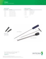
Dimensioned Illustrations (All dimensions are nominal)<br />
Catalog Number Description<br />
NL850-7210 Spetzler ® <strong>Lumbar</strong> <strong>Peritoneal</strong> <strong>Shunt</strong>, One-Piece, with Touhy Needle<br />
NL850-7460 Spetzler ® <strong>Lumbar</strong> <strong>Peritoneal</strong> Large Flushing Reservoir<br />
NL850-7440 Spetzler ® <strong>Lumbar</strong> <strong>Peritoneal</strong> Small Flushing Reservoir<br />
NL850-7420 Spetzler ® <strong>Lumbar</strong> <strong>Peritoneal</strong> In-Line Valve, Low Pressure<br />
NL850-7421 Spetzler ® <strong>Lumbar</strong> <strong>Peritoneal</strong> In-Line Valve, Medium Pressure<br />
NL850-7422 Spetzler ® <strong>Lumbar</strong> <strong>Peritoneal</strong> In-Line Valve, High Pressure<br />
NL75121-06 Connector<br />
NL82059-01 14-Gauge Touhy Needle, 3.5” (9cm)<br />
NL82059-02 Suture Collar<br />
NL82059-03 14-Gauge Touhy Needle, 6” (15.2 cm)<br />
Spetzler ® <strong>Lumbar</strong> <strong>Peritoneal</strong> Flushing Reservoir<br />
Large Reservoir<br />
Small Reservoir<br />
Inlet and Outlet Tube Size<br />
0.7 mm ID, 1.5 mm OD<br />
2.9 cm<br />
2.2 cm<br />
Inlet and Outlet Tube Size<br />
0.7 mm ID, 1.5 mm OD<br />
10<br />
1.2 cm<br />
0.6 cm<br />
ENGLISH<br />
FRANÇAIS<br />
DEUTSCH<br />
ITALIANO<br />
ESPAÑOL
Spetzler ® <strong>Lumbar</strong> <strong>Peritoneal</strong> <strong>Shunt</strong>. One-Piece<br />
18 cm<br />
Spetzler ® <strong>Lumbar</strong> <strong>Peritoneal</strong> In-Line Valve<br />
0.7 mm ID x 1.5 mm OD<br />
10 cm 5 cm<br />
80 cm<br />
11<br />
Four length marker dots spaced at 5 cm intervals<br />
Typical<br />
Connector * Suture Collar *<br />
14-Gauge Touhy Needle *<br />
1.2 cm<br />
15.2 cm (6”)<br />
2.1 cm<br />
3.2 cm<br />
9 cm (3.5”)<br />
5.2 mm<br />
* Also sold separately, non sterile. Use standard hospital protocol for sterilization.<br />
5 mm<br />
Suture Holes<br />
ENGLISH<br />
FRANÇAIS<br />
DEUTSCH<br />
ITALIANO<br />
ESPAÑOL
Systèmes de dérivation péritonéaux<br />
lombaires Spetzler ®<br />
Stérile - A usage unique.<br />
Description<br />
Les systèmes de dérivation lombopéritonéale<br />
Spetzler ® sont conçus pour<br />
dévier le liquide céphalo-rachidien<br />
(L.C.R.) de l’espace sous-arachnoïdien<br />
lombaire jusqu’au péritoine. Etant<br />
donné le faible diamètre de la tubulure<br />
du cathéter, la dérivation peut se faire<br />
par voie percutanée. Le cathéter<br />
lombaire est inséré dans l’espace sousarachnoïdien<br />
lombaire à travers une<br />
aiguille spinale de Touhy 14 G de 9 cm<br />
à embout Huber. Un passe-catheter et<br />
un trocart péritonéal peuvent être<br />
utilisés pour acheminer la section<br />
péritonéale du cathéter autour du flanc,<br />
jusqu’à la cavité péritonéale.<br />
Plusieurs dispositifs sont disponibles :<br />
un modèle une pièce sans réservoir ;<br />
des réservoirs petits ou grands séparés<br />
contenant une valve anti-reflux, qui<br />
peuvent être utilisés pour le rinçage ;<br />
et une valve à onglet séparée (pression<br />
basse, moyenne ou haute), qui peut<br />
être utilisée lorsque l’utilisateur cherche<br />
à ralentir le débit.<br />
Repères de longueur<br />
Extrémité lombaire<br />
Figure 1. Système de dérivation lombo-péritonéale une pièce<br />
Modèle une pièce<br />
Le modèle de dérivation lombopéritonéale<br />
une pièce (Figure 1) est<br />
un cathéter en silicone imprégné de<br />
baryum dont l’une extrémité présente<br />
les caractéristiques de l’extrémité<br />
proximale d’un cathéter lombaire et<br />
l’autre celles de l’extrémité distale d’un<br />
cathéter péritonéal. Ce cathéter est<br />
d’une longueur suffisante (80 cm) pour<br />
contourner un adulte moyennement<br />
obèse sur le flanc. Un réservoir de<br />
rinçage n’est pas intégré au modèle<br />
une pièce.<br />
Trois bagues d’application de sutures<br />
mobiles distinctes, fournies avec le<br />
modèle une pièce, servent à fixer le<br />
cathéter aux extrémités et au centre<br />
sur les tissus sous-cutanés aux sites<br />
d’incision lombaire, abdominal et sur<br />
le flanc.<br />
Une aiguille de Touhy 14 G de 9 cm est<br />
fournie pour l’insertion de l’extrémité<br />
lombaire du cathéter dans l’espace<br />
sous-arachnoïdien.<br />
Bague d’application de sutures<br />
Extrémité péritonéale<br />
12<br />
STERILE EO 2<br />
0123<br />
NL850-7210 NL850-7440 NL850-7460<br />
NL850-7420 NL850-7421 NL850-7422<br />
Etant donné sa conception, ce modèle<br />
s’implante plus facilement par des<br />
techniques essentiellement<br />
percutanées. Il peut intervenir dans des<br />
procédures diagnostiques, ainsi que<br />
dans le traitement d’une hydrocéphalie.<br />
Dans la mesure où il n’est pas utilisé<br />
avec un réservoir, il peut se retirer<br />
facilement lorsqu’aucun bénéfice<br />
thérapeutique n’est constaté.<br />
L’extrémité proximale (ou lombaire)<br />
du cathéter une pièce (Figure 2) est<br />
ouverte et coupée en biais. Son<br />
extrémité est multiperforée sur 18 mm<br />
environ pour améliorer le débit et<br />
diminuer le risque d’occlusion. La<br />
silicone plus raide diminue les risques<br />
de formation de coudes et de plis au<br />
niveau où le cathéter émerge entre les<br />
lames avant de s’acheminer jusqu’au<br />
flanc. Quatre repères de longueur noirs<br />
imprégnés de tantale sont placés à<br />
l’extrémité lombaire (proximale) du<br />
cathéter (Figure 1). Le premier repère<br />
(le plus proche de l’utilisateur) s’aligne<br />
sur l’encoche de la garde de l’aiguille<br />
de Touhy lorsque l’extrémité lombaire<br />
Extrémité ouverte<br />
Perforations<br />
Figure 2. Extrémité lombaire du cathéter<br />
ENGLISH<br />
FRANÇAIS<br />
DEUTSCH<br />
ITALIANO<br />
ESPAÑOL
Valve fendue<br />
Extrémité<br />
imprégnée de tantale<br />
Figure 3. Extrémité péritonéale du cathéter<br />
Connecteur<br />
Cathéter lombaire Cathéter péritonéal<br />
Figure 4. Jonction d’un cathéter de<br />
dérivation une pièce coupé sans réservoir<br />
est insérée dans l’aiguille de sorte que<br />
l’extrémité du cathéter se trouve près<br />
de la pointe de l’aiguille. Les autres<br />
repères sont espacés de 5 cm par<br />
rapport au premier repère pour<br />
permettre au chirurgien de mesurer la<br />
longueur de cathéter implantée dans<br />
l’espace sous-arachnoïdien lombaire.<br />
L’extrémité distale (ou péritonéale) du<br />
cathéter une pièce (Figure 3) possède<br />
une extrémité en silicone imprégnée<br />
de tantale radio-opaque. Deux fentes<br />
bilatérales (formant quatre fentes dans<br />
la paroi du cathéter), espacées de 90°<br />
(direction radiale) et de 3 mm (direction<br />
axiale) assurent la régulation de la<br />
pression et empêchent le reflux et<br />
les risques d’occlusion à l’extrémité<br />
distale.<br />
Un connecteur distinct en acier<br />
inoxydable est fourni avec le modèle<br />
une pièce. Si le chirurgien est amené<br />
à couper le cathéter, les extrémités<br />
coupées peuvent être réunies à l’aide<br />
de ce connecteur (Figure 4).<br />
Repères de longueur<br />
Ligatures (2)<br />
Connecteurs<br />
Bague d’application<br />
de sutures<br />
Cathéter lombaire<br />
Figure 5. Système de dérivation lombo-péritonéale trois pièces<br />
Réservoir<br />
L’utilisateur peut créer un système<br />
de dérivation lombo-péritonéale trois<br />
pièces (Figure 5) en commandant un<br />
réservoir et en coupant le cathéter une<br />
pièce en son point central. A l’aide des<br />
deux connecteurs en acier inoxydable<br />
fournis avec le réservoir, les sections<br />
lombaire et péritonéale de la dérivation<br />
peuvent être montées sur un réservoir<br />
et ligaturées en place. (Voir le Mode<br />
d’emploi.)<br />
Les deux modèles de réservoir, grand<br />
ou petit, incluent une valve à onglet antireflux<br />
dans l’orifice d’entrée du dôme<br />
du réservoir. Cette valve empêche le<br />
reflux de liquide vers l’espace sousarachnoïdien.<br />
La capacité du grand<br />
réservoir est supérieure à celle d’autres<br />
réservoirs Integra NeuroCare LLC. Le<br />
grand réservoir facilite la palpation et<br />
est plus facile à utiliser pour le rinçage<br />
du cathéter péritonéal, pour l’injection<br />
d’un radionucléide afin d’évaluer le<br />
fonctionnement de la dérivation ou<br />
pour le prélèvement de L.C.R. Le petit<br />
réservoir peut s’avérer préférable sur<br />
les patients à peau fine (patients plus<br />
minces) ou par souci d’esthétique.<br />
Le sens de circulation du liquide est<br />
indiqué par une flèche gravée sur le<br />
dessus du dôme du réservoir (Figure 6).<br />
Le réservoir (Figure 6) est connecté aux<br />
cathéters en montant les connecteurs<br />
en acier inoxydable fournis sur les<br />
extrémités lombaire et péritonéale<br />
du cathéter une pièce coupé en deux,<br />
puis en glissant l’ensemble dans les<br />
tubulures du réservoir. Une ligature est<br />
placée autour de chaque connecteur<br />
et tubulure (quatre au total) pour fixer<br />
et rendre les connecteurs étanches.<br />
Les ligatures ne doivent pas êtres<br />
serrées au point de sectionner la<br />
Ligatures<br />
Réservoir de rinçage<br />
Bord de la base -<br />
application de sutures<br />
Cathéter péritonéal<br />
13<br />
tubulure. La base du réservoir peut<br />
être fixée par des fils de suture sur les<br />
tissus sous-cutanés.<br />
Valve en série<br />
Il est possible de ralentir le débit en<br />
plaçant une petite valve à onglet dans<br />
un boîtier cylindrique en tout point du<br />
cathéter lombo-péritonéal. Cette valve<br />
est disponible dans les modèles<br />
pression basse, moyenne et haute<br />
et contient des connecteurs en acier<br />
inoxydable intégrés qui facilitent<br />
l’insertion au moment de l’implantation<br />
ou lors d’une reprise chirurgicale. Le<br />
sens d’écoulement du liquide est<br />
indiqué par une flèche radio-opaque<br />
qui figure sur le boîtier de la valve. La<br />
gamme de pression différentielle est<br />
identifiée par un point de silicone<br />
imprégné de tantale sur le boîtier de la<br />
valve. Voir le tableau de performance<br />
de la valve.<br />
Valeurs de pression<br />
Etant donné que le système de<br />
dérivation lombo-péritonéal s’implante<br />
au niveau de la région lombaire de la<br />
colonne vertébrale, il fournit une<br />
résistance relativement élevée à<br />
l’écoulement de liquide céphalorachidien.<br />
La régulation de pression<br />
s’obtient par l’action conjuguée de<br />
la valve à fentes doubles (extrémité<br />
péritonéale) et du petit diamètre interne<br />
(0,7 mm) de la tubulure du cathéter.<br />
Les caractéristiques de performance du<br />
cathéter sont établies conformément à<br />
une méthode de test de performance<br />
des dérivations de l’American Society<br />
for Testing and Materials F647-79,<br />
« Pratiques standard d’évaluation et<br />
de spécification des ensembles de<br />
dérivation implantables pour application<br />
neurochirurgicale ».<br />
Extrémité lombaire<br />
Tubulure<br />
Flèche gravée<br />
d’arrivée<br />
Ligatures (4)<br />
Valve à<br />
onglet<br />
Connecteur<br />
Bord de la base -<br />
application de<br />
Tubulure<br />
sutures<br />
Extrémité péritonéale<br />
Figure 6. Réservoir. Illustration de l’installation<br />
des sections lombaire et péritonéale<br />
du cathéter<br />
ENGLISH<br />
FRANÇAIS<br />
DEUTSCH<br />
ITALIANO<br />
ESPAÑOL
Indications<br />
La dérivation lombo-péritonéale<br />
percutanée peut servir à traiter une<br />
hydrocéphalie communicante. Elle<br />
est conçue pour acheminer le L.C.R. de<br />
l’espace sous-arachnoïdien lombaire à<br />
la cavité péritonéale.<br />
La dérivation peut être utilisée pour<br />
diagnostiquer, évaluer ou traiter une<br />
hydrocéphalie communicante de<br />
pression normale.<br />
Une dérivation lombo-péritonéale<br />
percutanée est également utile à<br />
la gestion de fistules de liquide<br />
céphalo-rachidien persistantes, de<br />
décompressions sous-occipitales et<br />
crâniennes proéminentes et de défauts<br />
d’absorption de L.C.R. passagers, à<br />
savoir hydrocéphalie post-méningitique<br />
ou hydrocéphalie post-hémorragique.<br />
L’utilisation de la valve en série, vendue<br />
séparément du système, est indiquée là<br />
où un ralentissement d’écoulement du<br />
liquide est souhaité pour soulager les<br />
symptômes de pression basse chez le<br />
faible pourcentage de patients qui,<br />
après un drainage normal et dans le<br />
courant normal de leur traitement,<br />
développent de tels symptômes.<br />
Contre-indications<br />
Les systèmes de dérivation lombopéritonéale<br />
ne doivent pas être utilisés<br />
dans le cas d’une hydrocéphalie non<br />
communicante.<br />
Les systèmes de dérivation lombopéritonéale<br />
ne doivent pas être utilisés<br />
en présence d’infections connues ou<br />
suspectées le long du parcours de<br />
dérivation (méningite, ventriculite,<br />
infections cutanées, bactériémie,<br />
septicémie ou péritonite). Il est<br />
conseillé d’éviter les procédures de<br />
dérivation si une infection est présente<br />
en un point quelconque du corps.<br />
Les systèmes de dérivation lombopéritonéale<br />
sont contre-indiqués<br />
lorsque des anomalies rachidiennes<br />
empêcheraient l’insertion normale du<br />
cathéter lombaire.<br />
L’utilisation de dérivations péritonéales<br />
lombaires est contre-indiquée chez les<br />
nourrissons sur lesquels l’extrémité<br />
inférieure du cordon rachidien n’a pas<br />
encore atteint la position L1-2 en<br />
direction céphalique.<br />
Etant donné le rétrécissement prononcé<br />
du canal lombo-sacré chez les patients<br />
achondroplasiques, l’implantation d’une<br />
dérivation lombaire dans l’espace sousarachnoïdien<br />
est contre-indiquée.<br />
La méthode d’introduction du<br />
cathéter péritonéal avec trocart<br />
est contre-indiquée en cas d’interventions<br />
chirurgicales abdominales<br />
passées ou d’obésité excessive.<br />
Mode d’emploi<br />
L’introduction d’un système de<br />
dérivation pouvant être exécutée par<br />
diverses techniques chirurgicales, il<br />
incombe au chirurgien de choisir celle<br />
qu’il juge la mieux adaptée au patient<br />
de par son expérience et sa formation.<br />
Test de perméabilité de la dérivation<br />
Les composants de chaque modèle<br />
de dérivation doivent être testés avant<br />
l’implantation. Les procédures<br />
suivantes son recommandées :<br />
Modèle une pièce et modèle trois<br />
pièces assemblé<br />
En maintenant l’asepsie, insérer une<br />
aiguille de seringue atraumatique 20 G<br />
dans le plus distal des orifices d’arrivée<br />
latérale de l’extrémité lombaire<br />
(proximale). Rincer lentement la lumière<br />
de l’ensemble du système avec 5 à<br />
10 ml de solution isotonique stérile.<br />
La solution doit s’écouler librement des<br />
valves fendues à l’extrémité péritonéale<br />
(distale) - quatre fentes dans la paroi<br />
de la tubulure. Si les quatre fentes ne<br />
laissent pas la solution s’écouler librement,<br />
rouler délicatement la zone des<br />
fentes entre le pouce et l’index pour<br />
les ouvrir, puis répéter la procédure<br />
de rinçage.<br />
Remarque : Les fentes de la valve<br />
sont enduites de graphite qui minimise<br />
l’adhérence en cours de stockage et<br />
ne doivent être rincées avec aucune<br />
solution avant la vérification de la<br />
perméabilité, juste avant l’implantation.<br />
Test de perméabilité et de pression de<br />
la valve en série<br />
1. Connecter la longueur de tubulure<br />
stérile fournie à la tubulure d’arrivée de<br />
la valve et relever la tubulure au-dessus<br />
de la valve. Aucune tubulure ne doit être<br />
connectée au connecteur de sortie.<br />
14<br />
2. Placer la valve à l’horizontale sur la<br />
table de test.<br />
3. A l’aide d’une seringue, remplir la<br />
tubulure à 18 cm environ. Utiliser de<br />
l’eau dégazée stérile pour éliminer les<br />
bulles d’air de la tubulure et de la valve.<br />
4. Une fois la circulation à travers la<br />
tubulure et la valve établie, les examiner<br />
toutes deux pour vérifier l’élimination<br />
des bulles. Ne pas rincer la valve avec<br />
une seringue. La pression créée par<br />
un rinçage à la seringue déformerait<br />
temporairement la valve à onglet en<br />
silicone, ce qui produirait un résultat<br />
de test de pression anormalement bas.<br />
5. Lorsque le niveau d’eau atteint la<br />
gamme de pression prévue (basse : 15<br />
à 54 mmHg H2O ; moyenne : 55 à 94<br />
mmHg H2O ou haute : 95 à 150 mmHg<br />
H2O), un ralentissement visible du débit<br />
doit se produire.<br />
6. La pression de fermeture de la valve<br />
doit être vérifiée lorsque le niveau d’eau<br />
atteint la limite inférieure de la gamme.<br />
L’écoulement de la tubulure de sortie<br />
de la valve doit être inférieur ou égal<br />
à 0,15 ml/min lorsqu’il est mesuré à<br />
la limite inférieure de la gamme de<br />
pression. La pression est enregistrée en<br />
mesurant la distance entre la base de la<br />
valve et le haut de la colonne d’eau de<br />
la tubulure d’extension d’arrivée. Etant<br />
donné les caractéristiques des produits<br />
en silicone, certaines variations de<br />
performance de pression peuvent<br />
se produire.<br />
Instructions liées à la procédure<br />
Les informations suivantes portant<br />
sur l’utilisation des deux modèles<br />
de système de dérivation lombopéritonéale<br />
sont fournies par le<br />
Dr Robert Spetzler*, d’après son<br />
expérience dans le traitement<br />
chirurgical de patients atteints<br />
d’hydrocéphalie communicante.<br />
*Robert Spetzler, M.D.<br />
Directeur, Barrow Neurological Institute<br />
Président, Division de neurochirurgie<br />
350 West Thomas Road, Phoenix, AZ 85013<br />
ENGLISH<br />
FRANÇAIS<br />
DEUTSCH<br />
ITALIANO<br />
ESPAÑOL
Extrémité<br />
multiperforée<br />
enfilée<br />
sur 8 cm<br />
Aiguille de Touhy<br />
Cathéter lombaire<br />
Figure 7. Insertion de la partie lombaire du<br />
cathéter une pièce dans l’espace sousarachnoïdien<br />
Enfiler l’extrémité distale du<br />
cathéter dans la tubulure<br />
Introducteur<br />
de cathéter<br />
sous-cutané<br />
Aspiration facultative<br />
Extrémité du<br />
cathéter<br />
Figure 9. Insertion de l’extrémité distale du<br />
cathéter une pièce à travers l’incision<br />
pratiquée dans le flanc<br />
Modèle une pièce<br />
Remarque : Pour les détails de<br />
l’insertion du modèle une pièce,<br />
reportez-vous aux illustrations. Les<br />
détails concernant l’utilisation du<br />
modèle trois pièces avec réservoir<br />
figurent à la section suivante.<br />
1. Insérer une sonde de Foley dans<br />
la vessie pour minimiser le risque<br />
de perforation de la vessie lors de<br />
l’insertion du cathéter péritonéal.<br />
2. Nettoyer et envelopper d’un champ<br />
stérile le dos, le flanc et l’abdomen du<br />
patient en position latérale et les genoux<br />
repliés.<br />
Cathéter<br />
lombaire<br />
Bague d’application de sutures<br />
Aiguille de Touhy<br />
Cathéter lombaire<br />
Figure 8. Partie lombaire du cathéter une<br />
pièce en place<br />
Incision dans<br />
le flanc<br />
Retirer le passecatheter<br />
de cathéter<br />
sous-cutané<br />
Figure 10. Extrémité distale du cathéter une<br />
pièce insérée dans l’incision pratiquée dans<br />
le flanc<br />
3. Pratiquer une incision d’un centimètre<br />
entre l’apophyse épineuse de<br />
L4-5 ou L5-S1. Relever temporairement<br />
la tête de la table de 30° pour<br />
augmenter la pression dans l’espace<br />
sous-arachnoïdien lombaire.<br />
4. Insérer l’aiguille de Touhy 14 G de<br />
9 cm à paroi extra-mince fournie dans<br />
l’espace sous-arachnoïdien lombaire<br />
inférieur en dirigeant le biseau vers le<br />
cerveau ou le postérieur.<br />
5. Enfiler l’extrémité multiperforée<br />
ouverte du cathéter une pièce dans<br />
l’aiguille de Touhy sur 8 centimètres<br />
(Figure 7). Ramener la table d’opération<br />
à sa position normale.<br />
15<br />
Bague<br />
d’application<br />
de<br />
sutures<br />
Si le cathéter doit être rétracté et<br />
qu’une résistance est perceptible,<br />
retirer l’aiguille de Touhy de 0,5 cm<br />
environ, puis pousser le cathéter<br />
légèrement vers l’avant pour le<br />
libérer, avant de le retirer.<br />
6. Retirer l’aiguille du cathéter. Si la<br />
pression de L.C.R est supérieure à la<br />
résistance au flux de la dérivation une<br />
pièce, le L.C.R. s’échappe des valves<br />
fendues à l’extrémité distale de la<br />
dérivation une pièce.<br />
7. Placer une bague d’application de<br />
sutures autour du cathéter dans la zone<br />
lombaire et la suturer sur les tissus<br />
sous-cutanés pour maintenir le cathéter<br />
en place (Figure 8).<br />
8. Pratiquer une petite incision et y<br />
insérer le passe-catheter de cathéter<br />
sous-cutané malléable avec l’obturateur<br />
en place, par voie sous-cutanée, autour<br />
de l’incision lombaire. Cet instrument<br />
spécial, avec l’obturateur attaché, est<br />
malléable et peut être courbé pour<br />
faciliter cette procédure. Retirer<br />
l’obturateur et insérer l’extrémité distale<br />
du cathéter une pièce dans l’ouverture<br />
lombaire de le passe-catheter de<br />
cathéter sous-cutané.<br />
Enfiler délicatement le cathéter dans<br />
le passe-catheter. Veiller à ne pas<br />
endommager le cathéter : la valve<br />
fendue de l’extrémité péritonéale peut<br />
être déformée ou déchirée si une force<br />
trop importante y est appliquée. Si le<br />
cathéter n’avance pas facilement dans<br />
le passe-catheter, il peut être aspiré par<br />
succion douce depuis l’extrémité<br />
« flanc » de le passe-catheter de<br />
cathéter sous-cutané. (L’extrémité de le<br />
passe-catheter peut accepter une<br />
tubulure d’aspiration standard.)<br />
(Figure 9)<br />
Retirer le passe-catheter du cathéter en<br />
laissant l’extrémité « flanc » en position.<br />
Placer une bague d’application de<br />
sutures autour du cathéter à l’incision<br />
pratiquée dans le flanc et la suturer aux<br />
tissus sous-cutanés pour maintenir le<br />
cathéter en place (Figure 10).<br />
9. Pratiquer une petite incision à 2 cm<br />
sous le nombril au centre, à travers la<br />
ligne blanche.<br />
ENGLISH<br />
FRANÇAIS<br />
DEUTSCH<br />
ITALIANO<br />
ESPAÑOL
Avancer l’extrémité<br />
péritonéale du cathéter<br />
dans le passe-catheter<br />
Passecatheter<br />
de<br />
cathéter souscutané<br />
Figure 11. Insertion de l’extrémité<br />
péritonéale dans l’incision abdominale<br />
Incision<br />
abdominale<br />
Retirer le<br />
passe-catheter<br />
de cathéter<br />
sous-cutané<br />
Figure 12. Extrémité péritonéale du cathéter<br />
une pièce en position sous-cutanée<br />
Figure 13. Système une pièce en place<br />
10. Insérer le passe-catheter de<br />
cathéter sous-cutané avec l’obturateur<br />
en place à travers l’incision abdominale<br />
et par voie sous-cutanée jusqu’à<br />
l’incision du flanc. Retirer l’obturateur et<br />
insérer l’extrémité péritonéale du<br />
modèle une pièce dans l’ouverture de le<br />
passe-catheter de cathéter pratiquée<br />
dans le flanc. Enfiler délicatement le<br />
cathéter dans le passe-catheter. Si le<br />
cathéter n’avance pas facilement dans<br />
le passe-catheter, il peut être aspiré par<br />
succion douce, comme indiqué plus<br />
haut (Figure 11). Retirer le passecatheter<br />
du cathéter en laissant<br />
l’extrémité abdominale en position<br />
sous-cutanée (Figure 12).<br />
11. Si la dérivation doit être insérée<br />
dans la cavité à l’aide d’un trocart<br />
péritonéal, suivre la procédure<br />
recommandée suivante. Placer un<br />
clamp d’Allis sur l’aponévrose et tirer<br />
fermement sur la paroi abdominale.<br />
Insérer le trocart jusqu’à la cavité<br />
péritonéale par une petite incision<br />
pratiquée dans la couche superficielle<br />
de l’aponévrose sans cesser de tirer<br />
sur le clamp d’Allis. Retirer le trocart<br />
après l’insertion.<br />
Cette méthode d’introduction permet au<br />
trocart d’être enfilé à travers la partie la<br />
plus fine de la paroi abdominale, là où il<br />
est le moins susceptible de rencontrer<br />
des structures vasculaires ou<br />
nerveuses.<br />
12. Si le trocart n’est pas utilisé pour<br />
l’insertion du cathéter dans la cavité<br />
péritonéale, l’insérer sous observation<br />
directe.<br />
13. Insérer toute longueur tubulure en<br />
trop dans la cavité péritonéale. Placer<br />
une bague d’application de sutures<br />
autour du cathéter. Suturer la bague sur<br />
les tissus sous-cutanés. Fermer toutes<br />
les incisions de manière usuelle<br />
(Figure 13).<br />
Remarque : Lorsque les brides de la<br />
bague se rejoignent, la bague enserre la<br />
tubulure.<br />
14. Vérifier la perméabilité du système<br />
de dérivation en injectant 2 mCi<br />
d’albumine Technetium99m dans<br />
l’espace sous-arachnoïdien cervical ou,<br />
le cas échéant, dans le réservoir placé<br />
dans le flanc. Utiliser une caméra à<br />
scintillation pour suivre le cheminement<br />
de l’isotope jusqu’à la cavité<br />
péritonéale.<br />
16<br />
Modèle trois pièces (assemblé à partir<br />
du modèle une pièce coupé en deux et<br />
du réservoir)<br />
Couper le modèle une pièce au milieu<br />
pour créer une section lombaire et une<br />
section péritonéale. Elaguer chaque<br />
section à la longueur appropriée, si<br />
nécessaire. Préparer le patient comme<br />
pour la procédure du modèle une pièce<br />
(étapes 1 à 4 ci-dessus).<br />
5. Enfiler l’extrémité multiperforée<br />
ouverte de la section lombaire dans<br />
l’aiguille de Touhy sur 8 centimètres.<br />
Ramener la table d’opération à sa<br />
position normale.<br />
6. Retirer l’aiguille par-dessus le<br />
cathéter. Du liquide céphalo-rachidien<br />
transparent s’échappe de l’extrémité de<br />
la section de cathéter lombaire.<br />
Manipuler le cathéter avec<br />
précaution pour ne pas<br />
endommager sa tubulure.<br />
7. Introduire l’extrémité distale du<br />
cathéter lombaire dans le flanc en<br />
procédant comme avec le modèle<br />
une pièce. (Voir 8 ci-dessus, modèle<br />
une pièce.)<br />
8. Pratiquer une petite incision à 2 cm<br />
sous le nombril au centre, à travers la<br />
ligne blanche. Introduire le cathéter<br />
péritonéal dans l’incision abdominale<br />
en procédant comme pour le modèle<br />
une pièce. (Voir 10-13 ci-dessus,<br />
modèle une pièce.)<br />
9. Pour implanter un modèle trois<br />
pièces, insérer les connecteurs en acier<br />
inoxydable fournis dans les extrémités<br />
du cathéter lombo-péritonéal coupé<br />
avant de glisser chaque ensemble sur<br />
les tubulures du réservoir, au niveau de<br />
l’incision pratiquée dans le flanc. Le<br />
sens de circulation du liquide est<br />
indiqué par une flèche gravée sur le<br />
dessus du dôme du réservoir. Le<br />
réservoir est connecté de manière à ce<br />
que l’écoulement se fasse dans le sens<br />
de la flèche (lombaire à péritonéal).<br />
Fixer les cathéters aux connecteurs<br />
et au réservoir par des ligatures<br />
encerclantes simples (quatre exigées).<br />
Ne pas trop serrer les ligatures sous<br />
peine de sectionner la tubulure de<br />
dérivation.<br />
ENGLISH<br />
FRANÇAIS<br />
DEUTSCH<br />
ITALIANO<br />
ESPAÑOL
Tableau des gammes de pression/débit<br />
Modèle une pièce<br />
Débit (NL850-7210)<br />
5 ml/h 50 mm H 2 O<br />
50 ml/h 400 mm H2O Les valeurs indiquées dans ce tableau correspondent au<br />
point inférieur de la gamme 5 ml/h et au point supérieur de<br />
la gamme 50 ml/h.<br />
Pression (mm de H 2 O)<br />
400<br />
350<br />
300<br />
250<br />
200<br />
150<br />
100<br />
50<br />
0<br />
5 10 15 20 25 30 35 40 45 50<br />
Débit (ml/h)<br />
Gamme de pression d’une dérivation une pièce<br />
(NL850-7210)<br />
Remarque : L’ajout d’un réservoir (petit ou grand) au<br />
système de dérivation une pièce ajoutera une pression<br />
maximum de 50 mm H2O à un débit de 23 ml/h.<br />
Le raccourcissement du cathéter de 20 cm produira une<br />
diminution globale de la pression du système d’environ<br />
15 mm H2O à un débit de 23 ml/h.<br />
17<br />
Tableau de performance de la valve<br />
Pression Pression Pression<br />
basse moyenne haute<br />
Code/Point<br />
Gamme de pression mm H2O mm H2O mm H2O différentielle à 9 ml/h 15-54 55-94 95-150<br />
Gamme de pression/débit<br />
à 5 ml/h 15 mm H2O 50 mm H2O 85 mm H2O à 50 ml/h 115 mm H2O 200 mm H2O 310 mm H2O Remarque : Les valeurs indiquées dans le tableau de gamme<br />
de pression/débit correspondent au point inférieur de la gamme<br />
établie à 5 ml/h et au point supérieur de la gamme de 50 ml/h.<br />
Pression (mm de H 2 O)<br />
350<br />
300<br />
250<br />
200<br />
150<br />
100<br />
50<br />
0<br />
Valve pression<br />
haute<br />
Valve pression<br />
moyenne<br />
Valve pression<br />
basse<br />
5 10 15 20 25 30 35 40 45 50<br />
Débit (ml/h)<br />
Remarque : Les zones grisées décrivent la performance in<br />
vitro typique de la valve, telle que testée à la fabrication. Etant<br />
donné les caractéristiques des produits en silicone, certaines<br />
variations de performance de pression peuvent se produire qui<br />
n’ont, jusqu’à présent, pas compromis l’efficacité de régulation<br />
du débit ni le traitement de l’hydrocéphalie. Chaque composant<br />
du système de dérivation a une incidence sur la résistance au<br />
flux globale du système. Pour déterminer la gamme de pression<br />
conjuguée approximative (pression de débit) fournie par la valve<br />
en série Spetzler ® avec le système une pièce, ajouter la pression<br />
donnée au tableau ci-dessus à un débit particulier à la pression<br />
figurant au tableau de pression du système une pièce au<br />
même débit.<br />
ENGLISH<br />
FRANÇAIS<br />
DEUTSCH<br />
ITALIANO<br />
ESPAÑOL
Cathéter<br />
lombaire<br />
Connecteur<br />
Ligatures<br />
encerclantes<br />
Incision dans<br />
le flanc<br />
Réservoir<br />
Sutures<br />
fixées aux<br />
tissus<br />
Figure 14. Installation du réservoir dans<br />
les tissus sous-cutanés du flanc (système<br />
trois pièces)<br />
Figure 15. Système trois pièces en place<br />
Cathéter lombaire<br />
Connecteur<br />
Ligatures (2)<br />
Cathéter péritonéal<br />
Figure 16. Jonction d’une dérivation une<br />
pièce sans réservoir<br />
10. Placer le réservoir en position<br />
sous-cutanée, au-dessus de la crête<br />
iliaque. Fixer le réservoir en glissant les<br />
fils de sutures à travers la base du<br />
réservoir et les tissus sous-cutanés<br />
(Figure 14). Fermer toutes les incisions<br />
de manière usuelle (Figure 15).<br />
11. Vérifier la perméabilité du système<br />
trois pièces comme au point 14 cidessus<br />
(modèle une pièce).<br />
Valve en série<br />
L’implantation d’une valve en série peut<br />
se faire de la même manière que le<br />
réservoir, aux exceptions près<br />
suivantes :<br />
1. La valve en série peut être implantée<br />
en tout point sous-cutané le long du<br />
système une pièce. Si elle est utilisée<br />
avec un réservoir et que le rinçage du<br />
système est nécessaire, placer la valve<br />
en série en position distale par rapport<br />
au réservoir.<br />
2. Etant donné que la valve en série<br />
contient des connecteurs intégrés aux<br />
extrémités d’arrivée et de sortie, une<br />
seule ligature est requise à chaque<br />
extrémité pour le raccordement au<br />
cathéter (deux requises au total).<br />
Comme avec les autres systèmes,<br />
vérifier la perméabilité du système créé<br />
avec la valve en série en procédant<br />
comme au point 14 ci-dessus (modèle<br />
une pièce).<br />
Connecteur<br />
Si le chirurgien se voit obligé de couper<br />
le modèle une pièce pour en ajuster la<br />
longueur, il devra utiliser le connecteur<br />
en acier inoxydable fourni avec le<br />
modèle une pièce. Insérer ce connecteur<br />
dans une section de cathéter, puis<br />
dans l’autre, avant de fixer chacune en<br />
position par une ligature encerclante<br />
(Figure 16). Fermer les bagues<br />
d’application de sutures moulées à<br />
chaque extrémité et les suturer aux<br />
tissus sous-cutanés. Fermer toutes<br />
les incisions de manière usuelle.<br />
Présentation<br />
Le modède de dérivation lombopéritonéale<br />
trois pièces n’est pas fourni<br />
comme un système complet. Les<br />
éléments requis pour monter une<br />
dérivation trois pièces sont : le cathéter<br />
de dérivation une pièce coupé en deux<br />
et la valve en série à connecteurs<br />
intégrés ou un réservoir de rinçage.<br />
Deux connecteurs en acier inoxydable<br />
sont fournis et emballés avec chaque<br />
réservoir.<br />
Le modèle de dérivation lombopéritonéale<br />
une pièce se présente sous<br />
la forme d’un cathéter lombo-péritonéal<br />
unique avec trois bagues d’application<br />
de sutures et un connecteur en acier<br />
inoxydable. Le connecteur est fourni au<br />
18<br />
cas où le cathéter doive être coupé ou<br />
raccourci. Une aiguille de Touhy 14 G<br />
de 9 cm est également fournie.<br />
Le modèle de dérivation lombopéritonéale<br />
une pièce est fourni dans un<br />
système d’emballage double stérile<br />
et sans pyrogène. Ce système à<br />
double épaisseur facilite le recours à<br />
la méthode préférée de transfert de<br />
produit stérile de la zone de circulation<br />
au champ stérile.<br />
Ne pas restériliser<br />
Ce produit doit être utilisé une seule<br />
fois.<br />
Avertissements<br />
Les patients hydrocéphaliques porteurs<br />
de systèmes de drainage de liquide<br />
céphalo-rachidien doivent être<br />
maintenus sous étroite surveillance,<br />
car ils peuvent afficher des signes et<br />
symptômes de pression intracrânienne<br />
causés par une défaillance de la<br />
dérivation. Ces signes et symptômes<br />
peuvent varier d’un patient à l’autre. Une<br />
hausse de la pression intracrânienne se<br />
caractérise par des maux de tête, des<br />
vomissements, une irritabilité, un<br />
apragmatisme, une somnolence,<br />
d’autres signes de dégradation de la<br />
conscience et une raideur de la nuque.<br />
La valve à onglet située dans les<br />
réservoirs de rinçage et la valve en<br />
série sont faites de caoutchouc de<br />
silicone qui, comme la plupart des<br />
caoutchoucs, peut coller à lui-même<br />
lorsqu’il est sec : en conséquence,<br />
le chirurgien doit vérifier que les<br />
composants de la valve sont mouillés<br />
et que le liquide s’écoule librement par<br />
la valve. (Voir le Mode d’emploi.)<br />
Précautions<br />
Avant l’intervention, les patients<br />
candidats à l’opération ou leurs<br />
représentants doivent être informés<br />
des éventuelles complications<br />
associées à ce produit.<br />
La tubulure de silicone doit être<br />
solidement fixée aux connecteurs<br />
intégrés de la valve en série, au<br />
réservoir ou au connecteur par des<br />
ligatures appliquées d’une manière<br />
permettant d’écarter le risque de<br />
sectionnement de la tubulure.<br />
La dérivation doit être fixée aux<br />
tissus sous-cutanés par des bagues<br />
ENGLISH<br />
FRANÇAIS<br />
DEUTSCH<br />
ITALIANO<br />
ESPAÑOL
d’application de sutures ou au niveau de<br />
la base du réservoir, aux trois sites<br />
d’incision.<br />
Etant donné la forme profilée et<br />
cylindrique de la valve en série, il est<br />
inutile de la fixer aux tissus sous-cutanés.<br />
La compatibilité médicamenteuse de ce<br />
produit n’a pas été testée et il n’est en<br />
conséquence pas recommandé pour<br />
l’administration de médications.<br />
POUR EVITER LA SECTION POSSIBLE<br />
DU CATHETER, NE JAMAIS RETIRER LE<br />
CATHETER PAR L’AIGUILLE TOUHY. IL<br />
FAUT DANS CE CAS LE RETIRER EN<br />
MEME TEMPS QUE L’AIGUILLE TOUHY.<br />
Integra NeuroSciences n’émet aucune<br />
garantie ou représentation quant aux<br />
caractéristiques de performance de ce<br />
produit s’il est utilisé avec les<br />
composants d’un autre fabricant.<br />
Complications<br />
Les complications éventuellement liées à<br />
l’utilisation de ce produit incluent les<br />
risques associés aux médicaments et<br />
méthodes utilisés au cours de l’intervention<br />
chirurgicale, de même que le<br />
degré d’intolérance du patient à tout objet<br />
étranger implanté dans le corps.<br />
Les principales complications liées à<br />
l’acheminement du liquide céphalorachidien<br />
dans l’oreillette droite ou le<br />
péritoine sont l’obstruction de la<br />
dérivation, un échec fonctionnel du<br />
système de dérivation, une infection<br />
ou une hypotension intracrânienne.<br />
Une occlusion de la dérivation peut se<br />
produire dans le cathéter lombaire ou<br />
péritonéal. Les tubulures péritonéales<br />
peuvent être bouchées par des particules<br />
telles que des caillots sanguins ou de la<br />
fibrine.<br />
La perte de perméabilité de la valvule<br />
et/ou du réservoir peut être causée par<br />
une obstruction du circuit des fluides par<br />
des particules telles que des caillots<br />
sanguins ou d’autres corps biologiques<br />
accumulés.<br />
L’échec fonctionnel du système de<br />
dérivation en raison d’un détachement de<br />
ses composants peut aboutir à la<br />
migration de la tubulure jusqu’à l’espace<br />
sous-arachnoïdien ou la<br />
cavité péritonéale.<br />
L’infection est une complication fréquente et<br />
sérieuse du système de dérivation ; elle est<br />
le plus souvent due à des contaminations<br />
cutanées. La septicémie, qui apparaît le<br />
plus souvent chez des nouveaux-nés<br />
affaiblis, peut résulter d’infections<br />
présentes n’importe où dans le corps, et<br />
peut se développer, accompagnée de peu<br />
ou pas de symptômes. Elle peut apparaître<br />
suite à une infection d’une plaie. La<br />
présence d’un corps étranger (comme le<br />
système de dérivation) peut déclencher une<br />
ventriculite ou une méningite latente.<br />
L’infection intra-cranienne peut être<br />
disséminée dans le corps via le cathéter<br />
distal.<br />
Le système de dérivation peut provoquer<br />
des lésions par rupture de la peau ou des<br />
tissus, lésions qui peuvent servir de foyer à<br />
des infections graves. En cas d’infection, le<br />
retrait du système de dérivation est<br />
recommandé en plus de la mise en oeuvre<br />
d’une thérapie appropriée.<br />
Une trop forte diminution de la pression<br />
intra-cranienne peut entraîner des<br />
complications, en particulier chez le<br />
nourrisson. Il peut s’agir d’hématomes subduraux,<br />
de dépressions marquées au niveau<br />
des fontanelles, d’un chevauchement des<br />
os du crâne, de passage d’une<br />
hydrocéphalie communicante à une<br />
hydrocéphalie bloquée par obstruction de<br />
l’aqueduc de Sylvius.<br />
Un dysfonctionnement du système de<br />
dérivation peut être mis en évidence<br />
par l’un ou l’ensemble des symptômes<br />
suivants : symptômes ininterrompus<br />
d’augmentation de la pression intracranienne,<br />
exsudation sous-cutanée de LCR<br />
le long du passage de la dérivation, et fuite<br />
de fluide par la plaie chirurgicale. Ces<br />
dysfonctionnements nécessitent un<br />
remplacement immédiat du système de<br />
dérivation ou de la partie en cause.<br />
D’autres complications signalées liées aux<br />
systèmes de dérivation, à la fois lombopéritonéale<br />
et lombo-urétérale, incluent une<br />
scoliose, une hyperlordose et une cyphoscoliose.<br />
La perforation des intestins ou<br />
d’organes par le système de dérivation est<br />
possible.<br />
Une occlusion urétérale unilatérale peut être<br />
causée par une tubulure de dérivation non<br />
fonctionnelle appuyant latéralement contre<br />
l’uretère. Les premiers signes et<br />
symptômes signalés sont généralement<br />
passagers, mais dans certains cas, ils sont<br />
19<br />
suffisamment graves pour nécessiter<br />
le retrait de la dérivation.<br />
Communication<br />
d’informations sur ce<br />
produit<br />
Integra NeuroSciences a sélectionné<br />
avec attention les matériaux et le<br />
procédé de fabrication de ce produit.<br />
Integra NeuroSciences exclut toutes<br />
garanties légales ou autres, explicites<br />
ou implicites, incluant en particulier,<br />
mais non exclusivement, les<br />
garanties concernant la qualité loyale<br />
et marchande ou l’aptitude du<br />
produit.<br />
Integra NeuroSciences ne peut être<br />
tenu pour responsable de tout<br />
incident ou sinistre, dommages et<br />
intérêts, ou utilisation du produit.<br />
Integra NeuroSciences n’assume ni<br />
n’autorise une quelconque personne<br />
à assumer en ses lieu et place,<br />
aucune responsabilité autre ou<br />
responsabilité liée au dispositif.<br />
Informations de<br />
commande<br />
Tous les produits peuvent être<br />
commandés auprès de votre<br />
représentant Integra NeuroSciences<br />
ou en contactant :<br />
Integra NeuroSciences<br />
311 Enterprise Drive<br />
Plainsboro, NJ 08536 USA<br />
Téléphone, : 1-800-654-2873<br />
Hors des États-Unis: 1-609-275-<br />
0500<br />
Fax: 609-275-5363<br />
ou<br />
Integra NeuroSciences<br />
Newbury Road, Andover<br />
Hampshire SP10 4DR England<br />
Téléphone: +44(0) 1264-345-700<br />
Fax: +44 (0) 1264-332-113<br />
Attention : Aux États-Unis, selon<br />
la loi fédérale, ce produit est<br />
exclusivement vendu par ou sur<br />
l’ordre d’un médecin. Ne pas<br />
utiliser si l’emballage a été<br />
ouvert ou endommagé.<br />
ENGLISH<br />
FRANÇAIS<br />
DEUTSCH<br />
ITALIANO<br />
ESPAÑOL
SYMBOLES INDIQUÉS SUR<br />
L’ÉTIQUETTE<br />
2<br />
LOT<br />
STERILE EO<br />
Consulter le mode<br />
d’emploi<br />
Date de péremption<br />
Ne pas réutiliser après<br />
ouverture de l’emballage<br />
Numéro de lot<br />
Stérile à moins que<br />
l’emballage n’ait été<br />
ouvert ou endommagé.<br />
Méthode de stérilisationoxyde<br />
d’éthylène.<br />
0123 Ce produit est conforme<br />
aux exigences de la<br />
directive 93/42/EEC<br />
relative aux dispositifs<br />
médicaux.<br />
20<br />
ENGLISH<br />
FRANÇAIS<br />
DEUTSCH<br />
ITALIANO<br />
ESPAÑOL
Illustration des dimensions (Toutes les dimensions sont nominales.)<br />
Numéro de réf. Description<br />
NL850-7210 Dérivation lombo-péritonéale Spetzler ® , une pièce, avec aiguille de Touhy<br />
NL850-7460 Grand réservoir de rinçage lombo-péritonéal Spetzler ®<br />
NL850-7440 Petit réservoir de rinçage lombo-péritonéal Spetzler ®<br />
NL850-7420 Valve en série lombo-péritonéale Spetzler ® pression basse<br />
NL850-7421 Valve en série lombo-péritonéale Spetzler ® pression moyenne<br />
NL850-7422 Valve en série lombo-péritonéale Spetzler ® pression haute<br />
NL75121-06 Connecteur<br />
NL82059-01 Aiguille de Touhy 14G, 9cm<br />
NL82059-02 Bague d’application de sutures<br />
NL82059-03 Aiguille de Touhy 14G, 15.2 cm<br />
Réservoir de rinçage lombo-péritonéal Spetzler ®<br />
Grand réservoir<br />
Petit réservoir<br />
Dimensions de la tubulure d’arrivée et de sortie :<br />
D.I. 0,7 mm, D.E. 1,5 mm<br />
2,9 cm<br />
2,2 cm<br />
Dimensions de la tubulure d’arrivée et de sortie :<br />
D.I. 0,7 mm, D.E. 1,5 mm<br />
21<br />
1,2 cm<br />
0,6 cm<br />
ENGLISH<br />
FRANÇAIS<br />
DEUTSCH<br />
ITALIANO<br />
ESPAÑOL
Dérivation lombo-péritonéale Spetzler ® , une pièce<br />
18 cm<br />
Valve lombo-péritonéale en série Spetzler ®<br />
D.I. 0,7 mm, D.E. 1,5 mm<br />
10 cm 5 cm<br />
80 cm<br />
22<br />
Quatre repères de longueur à 5 cm d’intervalle<br />
Typique<br />
Connecteur * Bague d’application de sutures *<br />
Aiguille de Touhy 14 G *<br />
1,2 cm<br />
15,2 cm<br />
2,1 cm<br />
3,2 cm<br />
5,2 mm<br />
5 mm<br />
* Aussi vendu séparément, non stérile. Utilisez le protocole standard hospitalier pour la stérilisation.<br />
9 cm<br />
Orifices d’insertion des fils de suture<br />
ENGLISH<br />
FRANÇAIS<br />
DEUTSCH<br />
ITALIANO<br />
ESPAÑOL
Spetzler ® Lumboperitonealer<br />
<strong>Shunt</strong>systeme<br />
Steril Nur zum einmaligen Gebrauch<br />
Beschreibung<br />
Die Spetzler ® lumboperitonealen <strong>Shunt</strong>systeme<br />
dienen zur Liquorableitung aus<br />
dem lumbalen Subarachnoidalraum in<br />
das Peritoneum. Wegen des kleinen<br />
Katheterschlauchdurchmessers kann<br />
die Ableitung perkutan durchgeführt<br />
werden. Der Lumbalkatheter wird durch<br />
eine 8,9 cm lange, 14 GA Touhy-Kanüle<br />
mit Huber-Spitze eingeführt. Mit Hilfe<br />
einer Katheterführung und eines<br />
<strong>Peritoneal</strong>trokars kann der <strong>Peritoneal</strong>katheterteil<br />
um die Flanke und in die<br />
<strong>Peritoneal</strong>höhle geführt werden.<br />
Die erhältlichen Vorrichtungen<br />
umfassen ein einteiliges Modell ohne<br />
Reservoir, separate große oder kleine<br />
Reservoirs mit Einwege-Ventil zur<br />
Anwendung bei Spülerfordernis, ein<br />
in Niedrig-, Mittel- und Hochdruckausführung<br />
erhältliches separates<br />
Kegelventil zur Anwendung bei<br />
zusätzlich benötigtem Widerstand.<br />
Einteiliges Modell<br />
Das einteilige lumboperitoneale<br />
<strong>Shunt</strong>modell (Fig. 1) besteht aus einem<br />
einzelnem, bariumimprägnierten<br />
Silikonelastomer-Katheter mit einem<br />
Längenmarkierungen<br />
lumbales Ende<br />
Abb. 1. Einteiliges lumboperitoneales <strong>Shunt</strong>-Modell<br />
Ende, das die Merkmale der proximalen<br />
Spitze des Lumbalkatheters, und einem<br />
Ende, das die Merkmale des distalen<br />
Endes des <strong>Peritoneal</strong>katheters aufweist.<br />
Der Katheter ist lange genug (80 cm),<br />
um um die Flanke eines Erwachsenen<br />
mit mäßiger Obesität herumzureichen.<br />
Das einteilige Modell enthält kein<br />
integriertes Spülreservoir.<br />
Mit Hilfe von drei beweglichen,<br />
separaten Nahtflänschen, die mit dem<br />
einteiligen Modell geliefert werden,<br />
werden beide Enden und der Mittelteil<br />
des Katheters am subkutanen Gewebe<br />
der lumbalen, Flanken- und<br />
abdominalen Inzisionsstellen befestigt.<br />
Eine mitgelieferte 8,9 cm, 14 GA<br />
Touhy-Kanüle dient zur Einführung<br />
des lumbalen Katheterendes in den<br />
Subarachnoidalraum.<br />
Aufgrund seines Designs kann dieses<br />
Modell einfacher durch eine im wesentlichen<br />
perkutane Methode eingeführt<br />
werden. Es eignet sich sowohl für<br />
diagnostische Zwecke als auch für die<br />
Behandlung von Hydrozephalus. Da es<br />
ohne Reservoir benutzt wird, kann es<br />
einfach entfernt werden, wenn kein<br />
therapeutischer Vorteil erzielt wird.<br />
Nahtflansch<br />
peritoneales Ende<br />
23<br />
STERILE EO 0123 2<br />
NL850-7210 NL850-7440 NL850-7460<br />
NL850-7420 NL850-7421 NL850-7422<br />
Das proximale oder lumbale Ende des<br />
einteiligen Kathetermodells (Abb. 2) ist<br />
offen und schräg angeschnitten. Zur<br />
Verbesserung des Durchflusses und<br />
Reduzierung einer Obstruktionsgefahr<br />
weist die Spitze über ca. 18 mm<br />
hinweg mehrere Perforationen auf. Das<br />
steifere Silikonelastomer reduziert die<br />
Möglichkeit eines Abknickens und eines<br />
Kollapses am Segment, an dem der<br />
Katheter zwischen den Laminae austritt<br />
und zur Flanke weitergeführt wird. Das<br />
lumbale (proximale) <strong>Shunt</strong>ende weist<br />
vier schwarze, mit Tantal imprägnierte<br />
Silikonelastomer-Längenmarkierungen<br />
auf. (Siehe Abb. 1.) Wenn das lumbale<br />
Ende so in die Kanüle eingeführt wird,<br />
daß sich die Katheterspitze neben der<br />
Kanülenspitze befindet, ist die erste<br />
(proximalste) Markierung mit der<br />
Öffnung im Ansatzstück der Touhy-<br />
Kanüle ausgerichtet. Die anderen<br />
Markierungen befinden sich in<br />
Abständen von 5 cm von der ersten<br />
Markierung und ermöglichen es dem<br />
Chirurgen, die in den lumbalen<br />
Subarachnoidalraum eingeführte<br />
Katheterlänge abzuschätzen.<br />
offenes Ende<br />
Perforationen<br />
Abb. 2. Spitze des Lumbalkatheters<br />
ENGLISH<br />
FRANÇAIS<br />
DEUTSCH<br />
ITALIANO<br />
ESPAÑOL
Schlitzventil<br />
tantalimprägnierte<br />
Spitze<br />
Abb. 3. Spitze des <strong>Peritoneal</strong>katheters<br />
Anschluß<br />
Lumbalkatheter <strong>Peritoneal</strong>katheter<br />
Abb. 4. Zusammenfügen eines durchtrennten,<br />
einteiligen <strong>Shunt</strong>s ohne Reservoir<br />
Das distale oder peritoneale Ende des<br />
einteiligen Kathetermodells (Abb. 3)<br />
weist eine röntgendichte, mit Tantal<br />
imprägnierte Silikonelastomerspitze<br />
auf. Zwei durchgehende Schlitze<br />
(d.h. insgesamt vier Schlitze in der<br />
Katheterwand) sind radial um 90º und<br />
axial um 3 mm versetzt, dienen zur<br />
Druckregelung und wirken einem<br />
Rückfluß und einer Obstruktion am<br />
distalen Ende entgegen.<br />
Das einteilige Modell wird mit einem<br />
separaten Edelstahlanschluß geliefert.<br />
Falls der Chirurg den Katheter durchschneiden<br />
muß, können die durchschnittenen<br />
Enden mit dem Anschluß<br />
zusammengefügt werden (Abb. 4).<br />
Reservoir<br />
Ein dreiteiliges lumboperitoneales<br />
<strong>Shunt</strong>system (Abb. 5) kann hergestellt<br />
werden, indem der Benutzer ein<br />
Reservoir und das einteilige <strong>Shunt</strong>modell<br />
bestellt, und dieses in der Mitte<br />
durchtrennt. Durch Benutzung der<br />
beiden Edelstahlanschlüsse, die mit<br />
Längenmarkierungen<br />
Nahtflansch<br />
Ligaturen (2)<br />
Anschlüsse<br />
lumbaler Katheter<br />
Spülreservoir<br />
Nahtbefestigung<br />
durch Basiskante<br />
Abb. 5. Dreiteiliges lumboperitoneales <strong>Shunt</strong>-System<br />
dem Reservoir geliefert werden, können<br />
die lumbalen und peritonealen <strong>Shunt</strong>enden<br />
mit einem Reservoir verbunden<br />
und durch Ligaturen an diesem<br />
befestigt werden. (Siehe<br />
Gebrauchsanleitung).<br />
Sowohl das große und das kleine<br />
Reservoir enthalten ein Einwege-<br />
Kegelventil in der Eingangsöffnung der<br />
Reservoirwölbung. Das Kegelventil<br />
wirkt einem Rückfluß der Flüssigkeit in<br />
den Subarachnoidalraum entgegen. Die<br />
Kapazität des großen Reservoirs ist<br />
größer als die von anderen Integra<br />
NeuroCare LLC-Reservoirs. Das große<br />
Reservoir verbessert die Tastbarkeit<br />
und erleichtert die Anwendung des<br />
Reservoirs zum Spülen des<br />
<strong>Peritoneal</strong>katheters, zur Injektion eines<br />
Radionukliden für die Beurteilung der<br />
<strong>Shunt</strong>-Funktion oder zur Entnahme von<br />
Liquorproben. Bei Patienten mit dünner<br />
Haut (z.B. dünnen Patienten) oder für<br />
kosmetische Zwecke kann jedoch die<br />
Anwendung des kleinen Reservoirs<br />
bevorzugt sein. Die Durchflußrichtung<br />
der Flüssigkeit wird durch einen in die<br />
Reservoirwölbung eingeformten Pfeil<br />
angezeigt. (Abb. 6).<br />
Der Anschluß des Reservoirs (Abb. 6)<br />
an die Katheter erfolgt durch Montage<br />
der mitgelieferten Edelstahlanschlüsse<br />
in die lumbalen und peritonealen Enden<br />
des durchtrennten einteiligen <strong>Shunt</strong>s,<br />
woraufhin die zusammengefügte Einheit<br />
in die Röhrchenstutzen auf der<br />
Reservoirwölbung aufgeschoben wird.<br />
Jedes Anschluß-/Röhrchenpaar wird<br />
mit einer Ligatur (insgesamt 4)<br />
versehen, um die Anschlüsse zu<br />
befestigen und abzudichten. Die<br />
Ligaturen dürfen nicht so fest<br />
angezogen sein, daß sie durch den<br />
Schlauch schneiden. Die<br />
Reservoirbasis kann am subkutanen<br />
Gewebe festgenäht werden.<br />
Ligaturen<br />
peritonealer Katheter<br />
24<br />
Inline-Ventil<br />
Ein zusätzlicher Durchflußwiderstand<br />
kann durch Einsatz eines kleinen<br />
Kegelventils mit zylindrischem Gehäuse<br />
an einem beliebigen Punkt im<br />
lumboperitonealen <strong>Shunt</strong> erhalten<br />
werden. Dieses Ventil ist für niedrige,<br />
mittlere und hohe Druckbereiche<br />
erhältlich und enthält integrierte<br />
Edelstahlanschlüsse zur einfachen<br />
Einführung während der ursprünglichen<br />
<strong>Shunt</strong>-Implantation oder einer späteren<br />
Berichtigung. Die Durchflußrichtung<br />
wird durch einen röntgendichten Pfeil<br />
auf dem Ventilgehäuse angegeben. Der<br />
Differentialdruckbereich wird mittels<br />
eines tantalimprägnierten<br />
Silikonelastomer-Punktecodes auf dem<br />
Ventilgehäuse identifiziert. Siehe<br />
Ventilleistungstabelle.<br />
Druckwerte<br />
Da das lumboperitoneale <strong>Shunt</strong>system<br />
auf der Höhe der lumbalen<br />
Rückgratregion implantiert wird, liefert<br />
es einen relativ hohen Widerstand<br />
gegen den Liquorfluß. Der Druck wird<br />
über die kombinierte Wirkung des<br />
doppelgeschlitzten Ventils am<br />
peritonealen Ende und des kleinen<br />
Innendurchmessers (0,7 mm) des<br />
Katheterschlauchs geregelt.<br />
Die Katheterleistungskennwerte werden<br />
in Übereinstimmung mit der <strong>Shunt</strong>-<br />
Leistungstestmethode der American<br />
Society for Testing and Materials F647-<br />
79, „Standard Practice for Evaluating<br />
and Specifying Implantable <strong>Shunt</strong><br />
Assemblies for Neurosurgical<br />
Application“, berichtet.<br />
lumbales Ende<br />
eingeformter Pfeil<br />
Einlaufröhrchen<br />
Ligaturen (4)<br />
Anschluß<br />
Kegelventil<br />
Nahtbefestigung<br />
Auslaufröhrchen<br />
durch Basisrand<br />
peritoneales Ende<br />
Abb. 6. Reservoir. Installation der lumbalen<br />
und peritonealen <strong>Shunt</strong>-Enden<br />
ENGLISH<br />
FRANÇAIS<br />
DEUTSCH<br />
ITALIANO<br />
ESPAÑOL
Indikationen<br />
Perkutane lumboperitoneale <strong>Shunt</strong>systeme<br />
können zur Behandlung eines<br />
Hydrocephalus communicans eingesetzt<br />
werden. Sie dienen zur Ableitung<br />
von Liquor aus dem lumbalen Subarachnoidalraum<br />
in die <strong>Peritoneal</strong>höhle.<br />
Der <strong>Shunt</strong> kann zur Diagnose,<br />
Beurteilung oder Behandlung eines<br />
Hydrocephalus communicans mit<br />
normalem Druck eingesetzt werden.<br />
Ein perkutaner lumboperitonealer <strong>Shunt</strong><br />
ist ebenso nützlich für das Management<br />
persistierender Liquorfisteln, ausgebeulter<br />
kranialer und subokzipitaler<br />
Dekompressionen und bei transitorischen<br />
Liquorabsorptionsdefekten,<br />
z.B. bei postmeningitischem oder<br />
posthämorrhagischem Hydrozephalus.<br />
Das als separates Systembauteil erhältliche<br />
Inline-Ventil ist indiziert, wenn ein<br />
zusätzlicher Widerstand erwünscht ist,<br />
um die Symptome eines niedrigen<br />
Drucks in dem kleinen Anteil von Patienten<br />
zu lindern, die diese Symptome<br />
nach normaler Drainage und bei normalem<br />
Behandlungsverlauf entwickeln.<br />
Kontraindikationen<br />
Lumboperitoneale <strong>Shunt</strong>systeme sollten<br />
nicht bei nichtkommunizierendem<br />
Hydrozephalus benutzt werden.<br />
Lumboperitoneale <strong>Shunt</strong>-Systeme<br />
dürfen nicht bei Vorliegen einer<br />
bekannten oder bei Verdacht auf eine<br />
Meningitis, Ventrikulitis, Hautinfektion,<br />
Bakteriämie, Sepsis oder Peritonitis<br />
verwendet werden. Es wird angeraten,<br />
beim Vorliegen einer Infektion im Körper<br />
auf <strong>Shunt</strong>-Eingriffe zu verzichten.<br />
Lumboperitoneale <strong>Shunt</strong>systeme<br />
sind kontraindiziert bei spinalen<br />
Anomalitäten, die keine freie Einführung<br />
des Lumbalkatheters zulassen.<br />
Lumboperitoneale <strong>Shunt</strong>systeme sind<br />
kontraindiziert in Säuglingen, bei denen<br />
das untere Ende des Rückenmarks<br />
noch nicht in die L1-2-Hirnwärtsposition<br />
gewandert ist.<br />
Wegen der deutlichen Verengung des<br />
lumbosakralen Kanals in achondroplastischen<br />
Patienten ist ein Lumbalkatheter<br />
im Subarachnoidalraum<br />
kontraindiziert.<br />
Die Einführung eines peritonealen<br />
Katheters unter Anwendung eines<br />
Trokars ist kontraindiziert im Fall<br />
vorausgehender Abdominaloperationen<br />
oder übermäßiger Obesität.<br />
Gebrauchsanweisung<br />
Die Einführung eines <strong>Shunt</strong>systems<br />
kann mit Hilfe mehrerer chirurgischen<br />
Methoden, vorgenommen werden.<br />
Dem Chirurgen wird daher am besten<br />
vorgeschlagen, diejenige Methode<br />
anzuwenden, die sich seiner eigenen<br />
Erfahrung und Ausbildung nach am<br />
besten für den Patienten anbietet.<br />
Anleitung für den <strong>Shunt</strong>-<br />
Durchgängigkeitstest<br />
Vor der Implantation sind die Komponenten<br />
jedes <strong>Shunt</strong>-Modells auf ihre Durchgängigkeit<br />
zu überprüfen. Dazu wird das<br />
folgende Vorgehen vorgeschlagen:<br />
Einteiliges Modell und<br />
zusammengefügtes dreiteiliges Modell<br />
Unter Anwendung aseptischer<br />
Maßnahmen eine stumpfe 20 GA<br />
Spritzennadel in die äußerste distale,<br />
seitliche Einlauföffnung am proximalen,<br />
lumbalen Ende einführen. Das Lumen<br />
des gesamten <strong>Shunt</strong>s mit 5 - 10 ml<br />
steriler, isotonischer Lösung vorsichtig<br />
durchspülen. Die Flüssigkeit sollte<br />
ungehindert aus den Schlitzventilen<br />
im distalen, peritonealen Ende (vier<br />
Schlitze in Schlauchwand) fließen. Falls<br />
die Flüssigkeit nicht ungehindert durch<br />
alle vier Schlitze fließt, den Schlitzventilbereich<br />
vorsichtig zwischen<br />
Daumen und Zeigefinger rollen, um<br />
die Schlitze zu öffnen. Die Spülung<br />
wiederholen.<br />
Hinweis: Die Ventilschlitze sind mit<br />
Graphit beschichtet, um eine Verklebung<br />
während der Lagerung zu<br />
reduzieren. Vor der unmittelbar vor<br />
der Implantation stattfindenden Durchgängigkeitsprüfung<br />
dürfen sie nicht<br />
mit Lösung gespült werden.<br />
Inline-Ventil<br />
Ventildurchgängigkeits- und<br />
Schließdrucktest<br />
1. Das mitgelieferte, sterile Schlauchstück<br />
an das Einlaufröhrchen des<br />
Ventils anschließen und den Schlauch<br />
höher als das Ventil plazieren. Es sollte<br />
kein Schlauch an den Ablaufanschluß<br />
angebracht werden.<br />
25<br />
2. Das Ventil horizontal zum Testtisch<br />
positionieren.<br />
3. Den Schlauch vorsichtig mit einer<br />
Spritze bis zu ca. 18 cm füllen. Dazu<br />
steriles, entlüftetes Wasser benutzen,<br />
um Luftblasen im Schlauch und im<br />
Ventil zu vermeiden.<br />
4. Nachdem der Durchfluß durch den<br />
Schlauch und das Ventil hergestellt<br />
wurde, Schlauch und Ventil darauf<br />
überprüfen, daß keine Luftblasen mehr<br />
vorliegen. Das Ventil nicht mit einer<br />
Spritze durchspülen. Der durch die<br />
Spritzenspülung erzeugte Druck verformt<br />
das Silikonelastomer-Kegelventil<br />
kurz, so daß sich abnormal niedrige<br />
Drucktestergebnisse einstellen können.<br />
5. Wenn der Wasserpegel sich innerhalb<br />
des Druckbereichsollwertes<br />
befindet (niedrig - 15 - 54 mm H2O,<br />
mittel - 55 - 94 mm H2O oder hoch -<br />
95 - 150 mm H2O), sollte sich der<br />
Durchfluß merklich verlangsamen.<br />
6. Der Ventilschließdruck sollte überprüft<br />
werden, wenn der Wasserpegel<br />
den niedrigeren Grenzwert erreicht. Der<br />
Ablauf aus dem Ventilablaufröhrchen<br />
sollte maximal 0,15 ml/min betragen,<br />
wenn die Messung am unteren Grenzwert<br />
des Druckbereiches vorgenommen<br />
wird. Der Druck wird durch Messung<br />
des Abstands von der Ventilbasis<br />
zum Oberrand der Wassersäule in<br />
der Einlaufschlauchverlängerung<br />
festgestellt. Aufgrund der Eigenschaften<br />
des Silikonelastomers kann die<br />
Druckleistung etwas schwanken.<br />
Operationsanleitung<br />
Die folgenden für die Anwendung<br />
beider lumboperitonealer <strong>Shunt</strong>systeme<br />
relevanten Informationen<br />
wurden von Dr. Robert Spetzler* auf<br />
der Basis seiner Erfahrungen bei<br />
der chirurgischen Behandlung von<br />
Patienten mit kommunizierendem<br />
Hydrozephalus zur Verfügung<br />
gestellt.<br />
*Robert Spetzler, M.D.<br />
Director, Barrow Neurological Institute<br />
Chairman, Neurosurgery Division<br />
350 W Thomas Rd, Phoenix, AZ 85013 USA<br />
ENGLISH<br />
FRANÇAIS<br />
DEUTSCH<br />
ITALIANO<br />
ESPAÑOL
mehrfach<br />
perforierte,<br />
Touhy-Kanüle<br />
8 cm tief<br />
eingeführte<br />
Lumbalkatheter<br />
Spitze<br />
Abb. 7. Einführung des Lumbalteils des<br />
einteiligen Katheters in den<br />
Subarachnoidalraum<br />
distales Katheterende<br />
durch Schlauch schieben<br />
subkutane<br />
Katheterführung<br />
Optionale Absaugung<br />
Katheterspitze<br />
Abb. 9. Einführung des distalen Endes eines<br />
einteiligen Katheters durch die<br />
Flankeninzision<br />
Einteiliges Modell<br />
Hinweis: Details über die Einführung<br />
des einteiligen Modells werden in den<br />
Abbildungen dargestellt. Ausführliche<br />
Informationen bezüglich der<br />
Anwendung des dreiteilen Modells mit<br />
Reservoirbefestigung befinden sich im<br />
Abschnitt nach dem Verfahren für das<br />
einteilige Modell.<br />
1. Um die Möglichkeit einer<br />
Blasenperforation beim Einführen des<br />
<strong>Peritoneal</strong>katheters zu minimieren,<br />
sollte ein Foley-Katheter eingelegt<br />
werden.<br />
2. Rücken, Flanke und Abdomen<br />
werden desinfiziert und abgedeckt,<br />
wobei sich der Patient in einer lateralen<br />
Lage mit angezogenen Knien befindet.<br />
lumbaler<br />
Katheter<br />
Nahtflansch<br />
Touhy-Kanüle<br />
Abb. 8. Lumbaler Teil des plazierten<br />
einteiligen Katheters<br />
Flankeninzision<br />
subkutane<br />
Katheterführung<br />
zurückziehen<br />
Abb. 10. Distales Ende des durch<br />
Flankeninzision plazierten, einteiligen<br />
Katheters<br />
3. Zwischen dem Dornfortsatz von<br />
L4-5 oder L5-S1 eine 1 cm lange<br />
Hautinzision vornehmen. Den Tischkopf<br />
vorübergehend um 30º erhöhen, um<br />
den Druck im lumbalen<br />
Subarachnoidalraum zu erhöhen.<br />
4. Die mitgelieferte 14 GA, 8,9 cm<br />
lange extradünnwandige Touhy-Kanüle<br />
in den unteren lumbalen Subarachnoidalraum<br />
einführen, wobei der Schliff<br />
hirnwärts oder kaudalwärts weist.<br />
5. Das offene, multiperforierte Ende<br />
des einteiligen Katheters 8 cm tief<br />
durch die Touhy-Kanüle einführen (Abb.<br />
7). Den Op-Tisch wieder in die normale<br />
Position zurückstellen.<br />
Falls der Katheter zurückgezogen<br />
werden muß und es wird ein<br />
Widerstand spürbar, die Touhy-<br />
26<br />
Nahtflansch<br />
Kanüle ca. 1/2 cm zurückziehen,<br />
und dann den Katheter etwas nach<br />
vorne schieben, um ihn zu lösen,<br />
und dann zurückziehen.<br />
6. Die Kanüle über dem Katheter<br />
zurückziehen. Falls der Liquordruck<br />
höher als der Flußwiderstand des<br />
einteiligen <strong>Shunt</strong>s ist, kann festgestellt<br />
werden, daß Liquor aus den<br />
Schlitzventilen im distalen Ende des<br />
einteiligen <strong>Shunt</strong>s entweicht.<br />
7. Einen einzigen Nahtflansch im<br />
Lumbalbereich um den Katheter legen<br />
und zur Katheterfixierung an das<br />
subkutane Gewebe annähen. (Abb. 8).<br />
8. Eine kleine Inzision in der Flanke<br />
machen und die flexible, subkutane<br />
Katheterführung mit eingesetztem<br />
Mandrin durch die Flankeninzision und<br />
subkutan zur Lumbalinzision<br />
herumführen. Dieses Sonderinstrument<br />
mit eingesetztem Mandrin ist flexibel<br />
und kann gebogen werden, um dieses<br />
Verfahren zu erleichtern. Mandrin<br />
abnehmen und das distale Ende des<br />
einteiligen Katheters in die lumbale<br />
Öffnung der subkutanen<br />
Katheterführung einführen.<br />
Den Katheter vorsichtig durch die<br />
Führung schieben. Es muß darauf<br />
geachtet werden, den Katheter<br />
nicht zu beschädigen, da das<br />
Schlitzventil des peritonealen Endes<br />
sich bei übermäßiger Kraftanwendung<br />
verformen bzw. reißen kann. Falls der<br />
Katheter sich nicht leicht durch die<br />
Führung vorschieben läßt, kann er<br />
durch Anwendung eines leichten Sogs<br />
am Flankenende der subkutanen<br />
Katheterführung durchgezogen werden.<br />
(Das Ende der Katheterführung kann<br />
mit einem standardmäßigen<br />
Absaugungsschlauch verbunden<br />
werden.) (Abb. 9).<br />
Die subkutane Katheterführung über<br />
den Katheter hinweg zurückziehen und<br />
dabei den Flankenteil stationär<br />
belassen. Einen einzigen Nahtflansch in<br />
der Flankeninzision um den Katheter<br />
legen und zur Katheterfixierung an das<br />
subkutane Gewebe annähen. (Abb. 10).<br />
9. Ca. 2 cm unter dem Nabel in der<br />
Medianlinie durch die Linea alba eine<br />
kleine Hautinzision vornehmen.<br />
10. Die subkutane Katheterführung<br />
mit eingesetztem Mandrin durch die<br />
ENGLISH<br />
FRANÇAIS<br />
DEUTSCH<br />
ITALIANO<br />
ESPAÑOL
<strong>Peritoneal</strong>spitze des<br />
Katheters in Führung<br />
einschieben<br />
subkutane<br />
Katheterführung<br />
Abb. 11. Einführung der <strong>Peritoneal</strong>spitze<br />
durch die Abdominalinzision<br />
Abdominalinzision<br />
subkutane<br />
Katheterführung<br />
zurückziehen<br />
Abb. 12. <strong>Peritoneal</strong>teil des subkutan<br />
plazierten, einteiligen Katheters<br />
Abb. 13. Plaziertes einteiliges System<br />
Abdominalinzision einführen und subkutan<br />
zur Flankeninzision herumführen.<br />
Mandrin entfernen und das peritoneale<br />
Ende des einteiligen Modells in die<br />
Flankenöffnung der Katheterführung<br />
einführen. Den Katheter vorsichtig<br />
durch die Führung schieben. Falls<br />
sich der Katheter nicht leicht durch<br />
die Führung schieben läßt, kann er<br />
wie vorstehend beschrieben durch<br />
Anwendung eines leichten Soges<br />
durchgezogen werden (Abb. 11). Die<br />
subkutane Katheterführung über den<br />
Katheter zurückziehen und dabei den<br />
Abdominalteil subkutan stationär<br />
zurücklassen. (Abb. 12).<br />
11. Falls der <strong>Shunt</strong> mit einem<br />
peritonealen Trokar in die<br />
<strong>Peritoneal</strong>höhle eingeführt werden soll,<br />
wird das folgende Verfahren empfohlen.<br />
Eine Allis-Klemme auf der Aponeurose<br />
befestigen und einen festen, nach<br />
außen wirkenden Zug auf die<br />
Bauchdecke ausüben. Den Trokar durch<br />
eine kleine Stichinzision in der obersten<br />
Schicht der Aponeurose in<br />
die <strong>Peritoneal</strong>höhle einführen und dabei<br />
weiterhin einen nach außen wirkenden<br />
Zug auf die Allis-Klemme ausüben. Den<br />
Trokar nach der Einführung entfernen.<br />
Durch diese Einführungsmethode kann<br />
der einzuführende Trokar durch den<br />
dünnsten Teil der Bauchdecke geführt<br />
werden, wo ein Auftreffen auf vaskuläre<br />
oder neurale Strukturen am<br />
unwahrscheinlichsten ist.<br />
12. Falls zur Einführung des Katheters<br />
in die <strong>Peritoneal</strong>höhle kein Trokar<br />
verwendet wird, den Katheter unter<br />
direkter Sichtkontrolle einführen.<br />
13. Die möglicherweise noch<br />
vorliegende ungestraffte Schlauchlänge<br />
in die <strong>Peritoneal</strong>höhle einführen. Einen<br />
Nahtflansch um den Katheterschlauch<br />
plazieren. Den Nahtflansch an das<br />
subkutane Gewebe annähen. Alle<br />
Inzisionen wie üblich verschließen.<br />
(Abb. 13).<br />
Hinweis: Beim Zusammenbringen der<br />
Nahtflanschenden wird der Flansch um<br />
den Schlauch herum angezogen.<br />
14. Die Durchgängigkeit des implantierten<br />
<strong>Shunt</strong>systems sollte durch<br />
Injektion von ca. 2 mCi Technetium99m Albumin in den zervikalen<br />
Subarachnoidalraum oder, falls benutzt,<br />
in das Reservoir in der Flanke überprüft<br />
27<br />
werden. Hierzu wird eine Szintillationskamera<br />
zur Verfolgung des Isotops in<br />
die <strong>Peritoneal</strong>höhle eingesetzt.<br />
Dreiteiliges Modell (aus<br />
durchtrenntem einteiligem Modell<br />
und Reservoir zusammengesetzt)<br />
Das einteilige Modell in der Mitte in ein<br />
lumbales und ein peritoneales Ende<br />
durchschneiden. Jedes Ende gegebenenfalls<br />
auf die korrekte Länge<br />
zuschneiden. Den Patienten wie<br />
vorstehend in Schritten 1-4 im<br />
Verfahren für das einteilige Modell<br />
beschrieben vorbereiten.<br />
5. Das offene, multiperforierte Ende<br />
des lumbalen Endes 8 cm tief durch die<br />
Touhy-Kanüle einführen. Den Op-Tisch<br />
wieder in die normale Position<br />
zurückstellen.<br />
6. Die Kanüle über dem Katheter<br />
zurückziehen. Es tritt klarer Liquor aus<br />
dem Ende des Lumbalkatheters aus.<br />
Den Katheter vorsichtig handhaben,<br />
um eine Beschädigung des<br />
Schlauchs zu vermeiden.<br />
7. Das distale Ende des Lumbalkatheters<br />
unter Anwendung desselben<br />
Verfahrens wie für das einteilige Modell<br />
in die Flanke einführen. (Siehe Anleitung<br />
für das einteilige Modell, Schritt 8.)<br />
8. Ca. 2 cm unter dem Nabel in der<br />
Medianlinie durch die Linea alba eine<br />
kleine Hautinzision vornehmen. Den<br />
<strong>Peritoneal</strong>katheter unter Befolgung<br />
desselben Verfahrens wie für das<br />
einteilige Modell in die Abdominalinzision<br />
einführen. (Siehe Anleitung für<br />
das einteilige Modell, Schritte 10 - 13.)<br />
9. Bei der Implantation eines dreiteiligen<br />
Modells die mitgelieferten Edelstahlanschlüsse<br />
in die lumbalen/<br />
peritonealen Enden des durchtrennten<br />
einteiligen <strong>Shunt</strong>s einführen, und diese<br />
Einheiten dann in die Röhrchen auf<br />
dem Reservoir an der Flankeninzision<br />
einschieben. Die Durchflußrichtung<br />
im Reservoir wird durch einen in die<br />
Reservoirwölbung eingeformten Pfeil<br />
angegeben. Das Reservoir wird so<br />
angeschlossen, daß die Flüssigkeit<br />
in Pfeilrichtung fließt (lumbal zu<br />
peritoneal). Die Katheter mit jeweils<br />
einer einzigen, umgebenden Ligatur an<br />
den Anschlüssen und am Reservoir<br />
ENGLISH<br />
FRANÇAIS<br />
DEUTSCH<br />
ITALIANO<br />
ESPAÑOL
Durchfluß-/Druckbereichstabelle<br />
Einteiliges Modell<br />
Durchflußrate (NL850-7210)<br />
5ml/hr. 50mm H 2 O<br />
50ml/hr. 400mm H2O Die in der Durchfluß-/Druckbereichstabelle aufgeführten<br />
Werte stellen den untersten Wert des 5 ml/h-Bereichs und<br />
den höchsten Wert des 50 ml/h-Bereichs dar.<br />
Druck — mm H 2 O<br />
400<br />
350<br />
300<br />
250<br />
200<br />
150<br />
100<br />
50<br />
0<br />
5 10 15 20 25 30 35 40 45 50<br />
Durchflußrate - ml/h<br />
Druckbereich eines einteiligen <strong>Shunt</strong>s (NL850-7210)<br />
Hinweis: Bei Benutzung eines großen oder kleinen<br />
Reservoirs mit dem einteiligen <strong>Shunt</strong>system wird ein<br />
Maximaldruck von 50 mm H2O bei einer Durchflußrate<br />
von 23 ml/h hinzugefügt.<br />
Ein Verkürzen der <strong>Shunt</strong>länge um 20 cm führt zu einer<br />
Gesamtabnahme des Systemdrucks von ca. 15 mm H2O<br />
bei einer Durchflußrate von 23 ml/h.<br />
28<br />
Ventilleistungstabelle<br />
Niedr. Mittl. Hoch<br />
Druck Druck Druck<br />
Punktecode<br />
Differentialdruck- mm H2O mm H2O mm H2O bereich bei 9 ml/h 15-54 55-94 95-150<br />
Durchfluß/Druck-bereich<br />
bei 5 ml/h 15 mm H2O 50 mm H2O 85 mm H2O bei 50 ml/h 115 mm H2O 200 mm H2O 310 mm H2O Hinweis: Die in der Durchfluß-/Druckbereichstabelle<br />
aufgeführten Werte stellen den untersten Wert des 5 ml/h-<br />
Bereichs und den höchsten Wert des 50 ml/H-Bereichs dar.<br />
Druck — mm H 2 O<br />
350<br />
300<br />
250<br />
200<br />
150<br />
100<br />
50<br />
0<br />
Hochdruckventil<br />
Mitteldruckventil<br />
Niedrigdruckventil<br />
5 10 15 20 25 30 35 40 45 50<br />
Durchflußrate - ml/h<br />
Hinweis: Die schattierten Bereiche stellen die Grenzwerte der<br />
in-vitro Ventilleistung zum Herstellungszeitpunkt dar. Aufgrund<br />
der Eigenschaften von Silikonmaterialien können Schwankungen<br />
in der Druckleistung auftreten, die jedoch erfahrungsgemäß die<br />
effektive Kontrolle und Behandlung des Hydrozephalus nicht<br />
beeinträchtigt haben. Jede Komponente eines <strong>Shunt</strong>systems<br />
wirkt sich auf den Gesamtdurchflußwiderstand des <strong>Systems</strong><br />
aus. Zur Bestimmung des ungefähren kombinierten Druckbereiches<br />
(Durchflußdruck) von Spetzler ® -Inline-Ventilen, die in<br />
ein einteiliges System eingeschaltet sind, wird der in der obigen<br />
Tabelle angegebene Druck bei einer bestimmten Durchflußrate<br />
zu dem Druck in der Drucktabelle für das einteilige System bei<br />
gleicher Durchflußrate addiert.<br />
ENGLISH<br />
FRANÇAIS<br />
DEUTSCH<br />
ITALIANO<br />
ESPAÑOL
Lumbalkatheter<br />
Anschluß<br />
umgebende<br />
Ligaturen<br />
Flankeninzision<br />
Reservoir<br />
an<br />
Gewebe<br />
annähen<br />
Abb. 14. Reservoirinstallation im<br />
subkutanen Flankengewebe (dreiteiliges<br />
System)<br />
Abb. 15. Plaziertes dreiteiliges System<br />
Lumbalkatheter<br />
Anschluß<br />
Ligaturen (2)<br />
<strong>Peritoneal</strong>katheter<br />
Abb. 16. Zusammenfügen eines durchtrennten,<br />
einteiligen <strong>Shunt</strong>s ohne Reservoir<br />
befestigen. (Insgesamt sind vier<br />
Ligaturen erforderlich.)<br />
Durch ein zu starkes Anziehen der<br />
Ligaturen kann der <strong>Shunt</strong>schlauch<br />
zerschnitten werden.<br />
10. Das Reservoir subkutan über dem<br />
Beckenkamm plazieren und durch den<br />
Reservoirbasisflansch am subkutanen<br />
Gewebe annähen. (Abb. 14). Alle<br />
Inzisionen wie üblich verschließen.<br />
(Abb. 15).<br />
11. Die Durchgängigkeit des dreiteiligen<br />
<strong>Systems</strong> wie für das einteilige Modell in<br />
Schritt 14 beschrieben überprüfen.<br />
Inline-Ventil<br />
Das Inline-Ventil kann ebenso wie das<br />
Reservoir implantiert werden, mit den<br />
folgenden Unterschieden:<br />
1. Das Inline-Ventil kann an jedem<br />
beliebigen Punkt im einteiligen System<br />
implantiert werden. Wird das Inline-<br />
Ventil mit einem Reservoir benutzt und<br />
das System soll durchspült werden, so<br />
muß das Inline-Ventil distal zum<br />
Reservoir angebracht werden.<br />
2. Da das Inline-Ventil an den Ein- und<br />
Ablaufenden integrale Anschlüsse<br />
aufweist, ist für den Anschluß an den<br />
Katheter an jedem Ende nur eine einzige<br />
Ligatur erforderlich (insgesamt zwei).<br />
Wie auch bei den anderen System ist<br />
die Durchgängigkeit des mit dem Inline-<br />
Ventil hergestellten <strong>Systems</strong> wie für das<br />
einteilige System unter Schritt 14<br />
vorstehend angegeben zu überprüfen.<br />
Anschluß<br />
Falls sich dem Chirurgen eine Situation<br />
stellt, in der das einteilige Modell auf<br />
eine andere Länge zurechtgeschnitten<br />
werden muß, wird hierzu der mit<br />
diesem Modell gelieferte Edelstahlanschluß<br />
benutzt. Dieser wird erst in<br />
ein, dann in das andere Katheterende<br />
eingeführt und dann mit einer einzigen,<br />
umgebenden Ligatur befestigt (Abb.<br />
16). Die angeformten Nahtflänsche<br />
an jedem Ende schließen und in das<br />
subkutane Gewebe einnähen. Alle<br />
Inzisionen wie üblich verschließen.<br />
Lieferform<br />
Das dreiteilige lumboperitoneale<br />
<strong>Shunt</strong>modell wird nicht als komplettes<br />
System geliefert. Es muß aus den<br />
folgenden Komponenten zusammengefügt<br />
werden: den durchtrennten<br />
einteiligen <strong>Shunt</strong> und dem Inline-Ventil<br />
mit integralen Anschlüssen oder einem<br />
Spülreservoir. Zwei Edelstahlanschlüsse<br />
werden mit jedem Reservoir verpackt<br />
mitgeliefert.<br />
Das einteilige lumboperitoneale <strong>Shunt</strong>modell<br />
wird als einzelner Lumbal-<br />
29<br />
<strong>Peritoneal</strong>-Katheter mit drei Nahtflänschen<br />
und einem Edelstahlanschluß<br />
geliefert. Der Anschluß wird für den<br />
Fall bereitgestellt, daß der Katheter<br />
durchschnitten oder gekürzt werden<br />
muß. Der Lieferumhang enthält auch<br />
eine 8,9 cm, 14 GA Touhy-Kanüle.<br />
Das einteilige lumboperitoneale<br />
<strong>Shunt</strong>modell wird in einem sterilen,<br />
pyrogenfreien, doppellagigen<br />
Verpackungssystem geliefert.<br />
Das doppelverpackte System ist das<br />
bevorzugte Transferverfahren für das<br />
sterile Produkt vom Springerbereich<br />
zum sterilen Feld.<br />
Nicht resterilisieren<br />
Dieses Produkt darf nur einmal benutzt<br />
werden.<br />
Warnungen<br />
Hydrocephalische Patienten mit Liquor-<br />
Dränagesystemen müssen aufmerksam<br />
auf Anzeichen und Symptome von<br />
intrakranialen Druckänderungen aufgrund<br />
von <strong>Shunt</strong>-Ausfall beobachtet<br />
werden. Diese Anzeichen und<br />
Symptome können von Patient zu<br />
Patient verschieden sein. Ein zunehmender<br />
intrakranialer Druck äußert sich<br />
durch Kopfschmerzen, Erbrechen,<br />
Reizbarkeit, Lustlosigkeit, Schläfrigkeit,<br />
andere Zeichen einer Bewußtseinsbeeinträchtigung<br />
und Nackensteife.<br />
Das Kegelventil in den Spülreservoirs<br />
und das Inline-Ventil bestehen aus<br />
Silikongummi, der wie die meisten<br />
Gummisorten mit sich selbst verkleben<br />
kann, wenn er trocken ist. Er sollte<br />
nicht anhaften, wenn er feucht ist. Der<br />
Chirurg muß daher sicherstellen, daß<br />
die Ventilkomponenten feucht sind,<br />
und daß die Flüssigkeit ungehindert<br />
durch das Ventil fließt. (Siehe<br />
Gebrauchsanleitung.)<br />
Vorsichtshinweise<br />
Vor der Operation sollten die<br />
zukünftigen Patienten bzw. ihre<br />
Vertreter über die möglichen<br />
Komplikationen, die mit diesem Produkt<br />
auftreten können, informiert werden.<br />
Der Silikonelastomerschlauch muß<br />
vorsichtig so mit Ligaturen an den<br />
integralen Anschlüsse auf dem Inline-<br />
Ventil, dem Reservoir oder einen<br />
Anschluß befestigt werden, daß der<br />
Schlauch nicht zerschnitten wird.<br />
ENGLISH<br />
FRANÇAIS<br />
DEUTSCH<br />
ITALIANO<br />
ESPAÑOL
Der <strong>Shunt</strong> sollte mit Nahtflänschen oder<br />
durch den Basisflansch des Reservoirs<br />
an allen drei Inzisionsstellen am<br />
subkutanen Gewebe befestigt werden.<br />
Wegen des flachen, zylindrischen<br />
Designs des Inline-Ventils muß dieses<br />
nicht am subkutanen Gewebe befestigt<br />
werden.<br />
Dieses Produkt wurde nicht auf<br />
Kompatibilität mit Wirkstoffen getestet<br />
und ist daher nicht zur Verabreichung<br />
von Arzneimitteln vorgesehen.<br />
UM EINE MÖGLICHE TRANSSEKTION<br />
DES KATHETERS ZU VERMEIDEN,<br />
DARF DIESER NIEMALS DURCH DIE<br />
TOUHY-NADEL ZURÜCKGEZOGEN<br />
WERDEN. FALLS DER KATHETER<br />
ZURÜCKGEZOGEN WERDEN MUSS,<br />
MÜSSEN DIE TUCHY-NADEL UND<br />
DER KATHETER GEMEINSAM<br />
ENTFERNT WERDEN.<br />
Integra NeuroSciences erhebt keinerlei<br />
Anspruch bzw. gibt keinerlei<br />
Zusicherungen bezüglich der Leistungscharakteristiken<br />
dieses Produktes,<br />
wenn es zusammen mit Komponenten<br />
anderer Hersteller benutzt wird.<br />
Komplikationen<br />
Zu den aus der Verwendung dieses<br />
Medizinprodukts möglicherweise<br />
erwachsenden Komplikationen gehören<br />
mit der Arzneimitteltherapie und den<br />
eingesetzten Op-Techniken einhergehende<br />
Risiken ebenso wie das<br />
Ansprechen, die Reaktion oder der<br />
Ausprägungsgrad der Unverträglichkeitsreaktion<br />
eines Patienten auf/gegen<br />
einen im Körper implantierten<br />
Fremdkörper.<br />
Die hauptsächlichen Komplikationen,<br />
die mit einem Umleiten des zerebrospinalen<br />
Liquors in den rechten Vorhof<br />
oder das Peritoneum in Verbindung<br />
gebracht werden sind <strong>Shunt</strong>-Obstruktion,<br />
Funktionsversagen des <strong>Shunt</strong>-<br />
<strong>Systems</strong>, Infektion oder intrakranialer<br />
Unterdruck.<br />
Eine Obstruktion des Flüssigkeitspfads<br />
durch Partikel, wie z.B. Blutgerinnsel<br />
oder andere biologische Ansammlungen,<br />
können zum Verlust der<br />
Durchgängigkeit des Ventils und/oder<br />
des Reservoirs führen.<br />
Ein Funktionsausfall des <strong>Shunt</strong>systems<br />
aufgrund abgetrennter Komponententeile<br />
kann zur Abwanderung des Schlauchs in<br />
den lumbalen Subarachnoidalraum oder<br />
in die <strong>Peritoneal</strong>höhle führen.<br />
Eine häufige und schwerwiegende<br />
Komplikation eines <strong>Shunt</strong>-<strong>Systems</strong><br />
besteht in Infektion, die am häufigsten<br />
durch Hautverunreinigungen verursacht<br />
wird. Eine bei geschwächten Säuglingen<br />
am häufigsten auftretende Sepsis kann<br />
aus Infektionen beliebiger Lokalisation<br />
resultieren und sich mit nur wenigen<br />
Symptomen oder völlig symptomlos<br />
ausbilden. Sie kann infolge einer Wundinfektion<br />
auftreten. Das Vorhandensein<br />
eines Fremdkörpers (d.h. des <strong>Shunt</strong>-<br />
<strong>Systems</strong>) kann Ventrikulitis oder eine<br />
latente Meningitis auslösen. Eine<br />
intrakraniale Infektion kann dann über den<br />
distalen Katheter durch den gesamten<br />
Körper disseminiert werden.<br />
Aus dem Abbau von Haut oder Gewebe<br />
über dem <strong>Shunt</strong>-System sich<br />
entwickelnde Läsionen können zudem als<br />
Herde schwerwiegender Infektionen<br />
dienen. Bei Auftreten einer Infektion<br />
ist zusätzlich zur entsprechenden<br />
Behandlung eine Entfernung des <strong>Shunt</strong>-<br />
<strong>Systems</strong> angezeigt.<br />
Übermäßige Senkung des Hirndrucks<br />
kann vor allem beim Säugling zu<br />
Komplikationen führen. Hierzu zählen<br />
subdurale Hämatome, deutlich eingesunkene<br />
Fontanellen, Überlagerung der<br />
Schädelknochen und die Konversion<br />
eines Hydrocephalus mit erhaltener<br />
Verbindung zu den Liquorräumen<br />
(H. communicans) hin zu einem Hydrocephalus<br />
ohne eine solche Verbindung<br />
aufgrund einer Obstruktion des Sylvius-<br />
Aquäduktes (Aquaeductus cerebri).<br />
Ein Versagen des <strong>Shunt</strong>-<strong>Systems</strong> kann<br />
durch ein beliebiges oder alle der folgenden<br />
Systeme offensichtlich werden:<br />
fortgesetzte Symptome erhöhten Hirndrucks,<br />
subkutane Liquorexsudation<br />
entlang des Verlaufsweges des <strong>Shunt</strong> und<br />
Flüssigkeitsaustritt aus der Op-Wunde.<br />
Ein solches Systemversagen erfordert<br />
das sofortige Auswechseln des <strong>Shunt</strong>-<br />
<strong>Systems</strong> oder der betroffenen<br />
Bestandteile.<br />
Andere berichtete Komplikationen<br />
von lumboperitonealen und lumbourethralen<br />
<strong>Shunt</strong>systemen umfassen<br />
Skoliose, Hyperlordose und Kypho-<br />
30<br />
skoliose. Der <strong>Shunt</strong>schlauch kann den<br />
Darm oder andere Organe perforieren.<br />
Durch einen nichtfunktionierenden<br />
<strong>Shunt</strong>schlauch, der seitlich gegen den<br />
Urether drückt, kann eine unilaterale<br />
urethrale Obstruktion verursacht werden.<br />
Die berichteten Ausgangszeichen<br />
und Symptome sind normalerweise<br />
transitorisch. In einigen Fällen können<br />
sie jedoch so schwer sein, daß sie eine<br />
Entfernung des <strong>Shunt</strong>s erfordern.<br />
Offenlegung von<br />
Produktinformationen<br />
Integra NeuroSciences hat bei<br />
der Auswahl der Werkstoffe und der<br />
Herstellung dieses Medizinprodukts<br />
angemessene Sorgfalt geübt. Integra<br />
NeuroNeuroSciences schließt sämtliche<br />
Garantiezusagen, ob ausdrücklich oder<br />
stillschweigend durch geltendes Recht<br />
oder auf sonstige Weise, aus, und zwar<br />
einschließlich, allerdings nicht begrenzt<br />
auf, jedweder implizierten Gewährleistungen<br />
hinsichtlich der Handelsfähigkeit<br />
und Gebrauchseignung. Integra<br />
NeuroNeuroSciences übernimmt<br />
keinerlei Haftung für direkt oder indirekt<br />
entstehende Verluste, Schäden oder für<br />
die Verwendung des Medizinprodukts.<br />
Keine dritte Person ist durch Integra<br />
NeuroNeuroSciences bevollmächtigt<br />
oder autorisiert, im Namen des<br />
Unternehmens jedwede anderslautende<br />
weitergehende Verpflichtung oder<br />
Gewährleistung im Zusammenhang mit<br />
diesem Medizinprodukt einzugehen.<br />
Produktbestellungsinformationen<br />
Alle Produkte können über Ihren Integra<br />
NeuroSciences Verkaufsrepräsentanten<br />
oder direkt wie folgt bezogen werden:<br />
Integra NeuroSciences<br />
311 Enterprise Drive<br />
Plainsboro, NJ 08536 USA<br />
Telefon: 1-800-654-2873<br />
Außerhalb der USA: 1-609-275-0500<br />
Fax: 609-275-5363<br />
oder<br />
Integra NeuroSciences<br />
Newbury Road, Andover<br />
Hampshire SP10 4DR England<br />
Telefon: +44(0) 1264-345-700<br />
Fax: +44 (0) 1264-332-113<br />
Vorsicht: Laut Gesetz ist der<br />
Verkauf dieses Produkts in den USA<br />
nur auf ärztliche Anordnung<br />
gestattet. Dieses Produkt darf nicht<br />
ENGLISH<br />
FRANÇAIS<br />
DEUTSCH<br />
ITALIANO<br />
ESPAÑOL
ETIKETTIERUNGSSYMBOLE<br />
2<br />
LOT<br />
STERILE EO<br />
Siehe<br />
Gebrauchsanweisung<br />
Verfallsdatum<br />
Nach dem Öffnem nicht<br />
wiederverwenden<br />
Chargennummer<br />
Produkt ist steril, es sei<br />
denn, die Verpackung<br />
wurde geöffnet oder<br />
beschädigt.<br />
Sterilisationsmethode-<br />
Ethylenoxid.<br />
0123 Das Produkt erfüllt die<br />
Anforderungen der<br />
Richtlinie 93/42/EWG für<br />
Medizinprodukte.<br />
31<br />
ENGLISH<br />
FRANÇAIS<br />
DEUTSCH<br />
ITALIANO<br />
ESPAÑOL
Abmessungszeichnungen (Alle Abmessungen sind Nennwerte)<br />
Katalog-Nr. Beschreibung<br />
NL850-7210 Spetzler ® Lumboperitonealer <strong>Shunt</strong>, einteilig, mit Touhy-Kanüle<br />
NL850-7460 Spetzler ® Lumboperitoneales, großes Spülreservoir<br />
NL850-7440 Spetzler ® Lumboperitoneales, kleines Spülreservoir<br />
NL850-7420 Spetzler ® Lumboperitoneales Inline-Ventil, niedrigdruck<br />
NL850-7421 Spetzler ® Lumboperitoneales Inline-Ventil, mitteldruck<br />
NL850-7422 Spetzler ® Lumboperitoneales Inline-Ventil, hochdruck<br />
NL75121-06 Anschluß<br />
NL82059-01 14 GA Touhy-Kanüle, 9cm<br />
NL82059-02 Nahtflansch<br />
NL82059-03 14 GA Touhy-Kanüle, 15.2 cm<br />
Spetzler ® Lumboperitoneales Spülreservoir<br />
Großes Reservoir<br />
Kleines Reservoir<br />
Einlauf- und Ablaufschlauchgröße<br />
0,7 mm ID, 1,5 mm AD<br />
2,9 cm<br />
2,2 cm<br />
Einlauf- und Ablaufschlauchgröße<br />
0,7 mm ID, 1,5 mm AD<br />
32<br />
1,2 cm<br />
0,6 cm<br />
ENGLISH<br />
FRANÇAIS<br />
DEUTSCH<br />
ITALIANO<br />
ESPAÑOL
Spetzler ® Lumboperitonealer <strong>Shunt</strong>, einteilig<br />
18 cm<br />
Spetzler ® Lumboperitoneales Inline-Ventil<br />
0,7 mm ID x 1,5 mm AD<br />
10 cm 5 cm<br />
80 cm<br />
33<br />
4 Längenmarkierungspunkte in 5 cm Intervallen<br />
typisch<br />
Anschluß * Nahtflansch *<br />
14 GA Touhy-Kanüle *<br />
1,2 cm<br />
15,2 cm<br />
2,1 cm<br />
3,2 cm<br />
5,2 mm<br />
* Auch individuell verkauft, nicht steril. Nutzen Sie ein Standardkrankenhausprotokoll für die Sterilisierung.<br />
9 cm<br />
5 mm<br />
Nahtöffnungen<br />
ENGLISH<br />
FRANÇAIS<br />
DEUTSCH<br />
ITALIANO<br />
ESPAÑOL
Sistemi di derivazione lombo<br />
peritoneale Spetzler ®<br />
Sterile Monouso<br />
Descrizione<br />
I sistemi di derivazione lombo<br />
peritoneale Spetzler ® ‚ sono stati studiati<br />
per derivare il liquor cefalorachidiano<br />
dallo spazio subaracnoideo lombare alla<br />
cavità peritoneale. Data la sezione ridotta<br />
del catetere, il sistema può essere<br />
impiantato per via percutanea. Il catetere<br />
lombare è inserito nello spazio subaracnoideo<br />
lombare attraverso un ago<br />
spinale di Touhy da 14 gauge (88,9 mm)<br />
con punta Huber. Per far passare il<br />
segmento peritoneale del catetere oltre<br />
il fianco, fino alla cavità peritoneale, si<br />
possono usare un passacatetere ed un<br />
trequarti peritoneale.<br />
Sono disponibili vari componenti: un<br />
modello in un unico pezzo senza<br />
serbatoio, un serbatoio grande o<br />
piccolo dotati di valvola non ritorno,<br />
utile per l’eventuale lavaggio, una<br />
valvola nelle versioni a bassa, media<br />
o alta pressione da usare quando si<br />
desidera un’ulteriore resistenza.<br />
Modello in un unico pezzo<br />
Il modello in un unico pezzo per<br />
derivazione lombo peritoneale<br />
(Figura 1) è un singolo catetere<br />
Marcatori di lunghezza<br />
Estremità lombare<br />
in elastomero di silicone impregnato di<br />
bario, un’estremità del quale è dotata<br />
delle caratteristiche della punta prossimale<br />
di un catetere lombare, mentre<br />
l’altra estremità ha le caratteristiche<br />
della punta distale di un catetere<br />
peritoneale. Il catetere è di lunghezza<br />
sufficiente (80 cm) a passare sul fianco<br />
di un adulto moderatamente obeso. Il<br />
modello in un unico pezzo non<br />
comprende il serbatoio.<br />
Al modello in un unico pezzo sono<br />
acclusi tre collari di sutura, che<br />
servono per fissare le estremità e la<br />
sezione centrale del catetere al tessuto<br />
sottocutaneo, presso i siti di incisione<br />
lombare, addominale e sul fianco.<br />
Per l’inserimento dell’estremità lombare<br />
del catetere nello spazio subaracnoideo<br />
è accluso un ago spinale di Touhy da<br />
14 gauge (88,9 mm).<br />
Questo modello, grazie al suo design, si<br />
inserisce più facilmente mediante<br />
tecniche percutanee. Esso può essere<br />
impiegato sia a fini diagnostici sia per il<br />
trattamento dell’idrocefalo. Non usato<br />
con un serbatoio, questo modello può<br />
Collare di sutura<br />
Figura 1. Modello in un unico pezzo per derivazione lombo peritoneale<br />
Estremità peritoneale<br />
34<br />
STERILE EO 0123 2<br />
NL850-7210 NL850-7440 NL850-7460<br />
NL850-7420 NL850-7421 NL850-7422<br />
essere facilmente rimosso se non si<br />
riscontrano vantaggi terapeutici.<br />
L’estremità prossimale o lombare del<br />
modello in un unico pezzo (Figura 2)<br />
è aperta e smussa. La punta ha fori<br />
multipli lungo circa 18 mm, per<br />
agevolare il flusso e ridurre la<br />
possibilità di occlusione. L’elastomero<br />
di silicone più rigido diminuisce il<br />
rischio di attorcigliamento e<br />
collabimento del segmento che emerge<br />
tra le lamine e prosegue verso il fianco.<br />
Quattro marcatori di lunghezza neri, in<br />
elastomero di silicone impregnato di<br />
tantalio, sono situati all’estremità<br />
lombare (prossimale) del catetere<br />
(Figura 1). Il primo marcatore (quello<br />
più prossimale) deve essere allineato<br />
all’apertura nel centro dell’ago di Touhy<br />
quando l’estremità lombare è inserita<br />
nell’ago, così che la punta del catetere<br />
viene a trovarsi vicino alla punta<br />
dell’ago. Gli altri marcatori sono ubicati<br />
ad intervalli di 5 cm, per consentire al<br />
chirurgo di valutare la lunghezza del<br />
segmento inserito nello spazio<br />
subaracnoideo lombare.<br />
Estremità aperta<br />
Fori<br />
Figura 2. Punta del catetere lombare<br />
ENGLISH<br />
FRANÇAIS<br />
DEUTSCH<br />
ITALIANO<br />
ESPAÑOL
Valvola a fessura<br />
Punta impregnata<br />
di tantalio<br />
Figura 3. Punta del catetere peritoneale<br />
Connettore<br />
Legature (2)<br />
Catetere lombare Catetere peritoneale<br />
Figura 4. Giunzione del catetere tagliato,<br />
senza serbatoio<br />
L’estremità distale o peritoneale del<br />
modello in un unico pezzo (Figura 3) ha<br />
una punta radiopaca in elastomero di<br />
silicone impregnato di tantalio. Due<br />
serie di valvole a fessura (per un totale<br />
di quattro fessure nella parete del<br />
catetere), ad intervalli di 90° in senso<br />
radiale e di 3 mm in senso assiale,<br />
regolano la pressione, contrastano<br />
il flusso di ritorno e riducono la<br />
possibilità di ostruzione all’estremità<br />
distale.<br />
Il modello in un unico pezzo è fornito<br />
con un connettore di acciaio inox,<br />
separato, con il quale è possibile<br />
congiungere le estremità recise, se<br />
è necessario tagliare il catetere<br />
(Figura 4).<br />
Serbatoio<br />
Un sistema di derivazione lomboperitoneale<br />
in tre pezzi (Figura 5) può<br />
essere ottenuto ordinando un serbatoio<br />
Marcatori di lunghezza<br />
Collare di sutura<br />
Connettori<br />
Catetere lombare<br />
Serbatoio<br />
Suturare attraverso<br />
la flangia<br />
Figura 5. Sistema di derivazione lombo peritoneale in tre pezzi<br />
ed il catetere di derivazione in un unico<br />
pezzo e tagliando quest’ultimo al<br />
centro. Con i due connettori di acciaio<br />
inox forniti con il serbatoio, i segmenti<br />
lombare e peritoneale della derivazione<br />
possono essere collegati al serbatoio<br />
e bloccati in sito mediante legature<br />
(consultare le Istruzioni per l’uso).<br />
Sia il serbatoio grande che quello<br />
piccolo sono corredati di una valvola<br />
mitrale unidirezionale ubicata nella<br />
cupola del serbatoio, vicino alla porta<br />
di ingresso. Questa valvola impedisce<br />
il flusso retrogrado nello spazio<br />
subaracnoideo. Il serbatoio grande, la<br />
cui capacità è superiore a quella di altri<br />
serbatoi Integra NeuroCare LLC,<br />
migliora la palpabilità ed agevola il<br />
lavaggio del catetere peritoneale,<br />
l’iniezione di radionucleotidi nella<br />
valutazione della funzionalità del<br />
sistema di derivazione e il campionamento<br />
del liquor. Si può optare per il<br />
serbatoio piccolo nei pazienti con cute<br />
sottile (per esempio, in soggetti magri)<br />
o per motivi estetici. La direzione<br />
del flusso è indicata da una freccia<br />
stampata sulla cupola del serbatoio<br />
(Figura 6).<br />
Il serbatoio (Figura 6) si collega al<br />
catetere tagliando quest’ultimo in due<br />
pezzi. Si assemblano i connettori di<br />
acciaio inox in dotazione sull’estremità<br />
lombare e peritoneale del catetere<br />
stesso e quindi si fissano ai tubi del<br />
serbatoio. Effetturare una legatura a<br />
ciascun tubo ed a ciascun connettore<br />
(per un totale di quattro legature),<br />
fissando e sigillando i connettori. Non<br />
stringere le legature fino al punto<br />
che possano tagliare i tubi. La<br />
flangia alla base del serbatoio può<br />
essere suturata al tessuto sottocutaneo.<br />
Legature<br />
Catetere peritoneale<br />
35<br />
Valvola In-Line<br />
Si può ottenere un’ulteriore resistenza<br />
al flusso inserendo una piccola valvola<br />
a forma cilindrica, in qualsiasi punto<br />
del sistema di derivazione lombo<br />
peritoneale. La valvola, disponibile<br />
in versioni a bassa, media ed alta<br />
pressione, dispone di connettori<br />
integrati in acciaio inox che ne facilitano<br />
l’inserimento al momento dell’impianto<br />
o nel caso di revisione. La direzione<br />
del flusso è indicata da una freccia<br />
radiopaca situata sul corpo della<br />
valvola. L’intervallo della pressione<br />
differenziale è indicato da un codice<br />
a punti in elastomero di silicone<br />
impregnato di tantalio situato sulla<br />
valvola. Consultare la tabella delle<br />
prestazioni delle valvole.<br />
Valori di pressione<br />
Poiché il sistema di derivazione lombo<br />
peritoneale deve essere impiantato<br />
a livello della regione lombare della<br />
colonna vertebrale, esso è stato<br />
concepito per fornire una resistenza<br />
relativamente elevata al flusso del<br />
liquor. La regolazione della pressione<br />
è ottenuta dall’azione combinata delle<br />
fessure all’estremità peritoneale e della<br />
ridotta sezione interna (0,7 mm/<br />
0,028 pollici) del catetere.<br />
Le caratteristiche di prestazione del<br />
catetere sono riportate secondo il<br />
metodo di prova delle prestazioni delle<br />
derivazioni stabilito in “Standard<br />
Practice for Evaluating and Specifying<br />
Implantable <strong>Shunt</strong> Assemblies for<br />
Neurosurgical Application”, F647-79<br />
della ASTM (American Society for<br />
Testing and Materials).<br />
Estremità lombare Freccia stampata<br />
Tubo di ingresso<br />
Legature (4)<br />
Valvola<br />
Connettore<br />
mitrale<br />
Suturare Tubo di uscita<br />
attraverso<br />
la flangia. Estremità peritoneale<br />
Figura 6. Collegamento del serbatoio ai<br />
segmenti lombare e peritoneale<br />
ENGLISH<br />
FRANÇAIS<br />
DEUTSCH<br />
ITALIANO<br />
ESPAÑOL
Indicazioni<br />
L’impianto percutaneo di un sistema di<br />
derivazione lombo peritoneale, progettato<br />
per derivare il liquor cefalorachidiano<br />
dallo spazio subaracnoideo<br />
lombare alla cavità peritoneale, può<br />
essere impiegato nel trattamento<br />
dell’idrocefalo comunicante.<br />
La derivazione può essere usata per la<br />
diagnosi, la valutazione ed il trattamento<br />
dell’idrocefalo comunicante a<br />
pressione normale.<br />
L’impianto percutaneo di un sistema di<br />
derivazione lombo peritoneale serve<br />
anche nella gestione di persistenti<br />
fistole di liquor, decompressioni<br />
suboccipitali e craniche prominenti,<br />
difetti transitori di assorbimento del<br />
liquor, per esempio in casi di idrocefalo<br />
post-emorragico o post-meningite.<br />
La valvola In-Line, disponibile come<br />
componente a parte, è indicata per<br />
l’uso nei casi in cui si voglia aggiungere<br />
una ulteriore resistenza al flusso di<br />
liquor per alleviare i sintomi della bassa<br />
pressione nella ridotta percentuale di<br />
pazienti che, dopo il normale drenaggio<br />
nel corso del normale trattamento,<br />
sviluppano tali sintomi.<br />
Controindicazioni<br />
I sistemi di derivazione lombo<br />
peritoneale non devono essere<br />
impiantati in soggetti affetti da<br />
idrocefalo non comunicante.<br />
L’impianto di sistemi di derivazione<br />
lombo peritoneale è controindicato in<br />
presenza di meningite, ventricolite,<br />
infezioni cutanee, batteriemia, setticemia<br />
o peritonite accertate o sospette.<br />
Si consiglia di evitare le procedure di<br />
derivazione in presenza di infezione in<br />
qualsiasi punto dell’organismo.<br />
L’impianto di sistemi di derivazione<br />
lombo peritoneale è controindicato<br />
in casi di anomalie spinali che<br />
ostacolerebbero l’inserimento del<br />
catetere lombare.<br />
L’impianto di sistemi di derivazione<br />
lombo peritoneale è controindicato in<br />
pazienti in età infantile quando l’estremità<br />
inferiore del midollo spinale non è<br />
ancora migrata verso la posizione L1-2.<br />
E’ controindicata la derivazione lombare<br />
nello spazio subaracnoideo in presenza<br />
di un marcato restringimento del canale<br />
lombosacrale in pazienti acondroplastici,<br />
L’introduzione del catetere<br />
peritoneale con un trequarti<br />
è controindicata in pazienti<br />
eccessivamente obesi o che in<br />
precedenza siano stati sottoposti<br />
ad interventi chirurgici addominali.<br />
Istruzioni per l’uso<br />
L’impianto di un sistema di derivazione<br />
può essere effettuato mediante varie<br />
tecniche chirurgiche; si consiglia<br />
pertanto al chirurgo di adottare il<br />
metodo che, in base alla sua esperienza<br />
ed alla sua formazione, meglio si addice<br />
al paziente.<br />
Istruzioni di verifica della pervietà<br />
del sistema<br />
La pervietà dei componenti di ciascun<br />
sistema di derivazione va verificata<br />
prima dell’impianto. Si raccomandano<br />
le procedure che seguono.<br />
Modello in un unico pezzo e modello<br />
in tre pezzi assemblato<br />
In condizione di asepsi, inserire un ago<br />
smusso da siringa da 20 gauge nel foro<br />
di ingresso laterale situato nella parte<br />
più distale all’estremità lombare<br />
prossimale. Lavare delicatamente il<br />
lume dell’intero sistema con 5-10 cc<br />
di soluzione isotonica sterile. Le quattro<br />
fessure distali all’estremità peritoneale<br />
distale devono permettere il passaggio<br />
incontrastato del liquido. Se le quattro<br />
fessure non consentono il passaggio<br />
incontrastato del liquido, ruotare<br />
delicatamente la sezione fessurata fra<br />
il pollice e l’indice per stabilire il flusso<br />
attraverso tutte le fessure e ripetere la<br />
procedura di lavaggio.<br />
Nota: le fessure sono rivestite di grafite<br />
per ridurre al minimo l’aderenza durante<br />
l’ immagazzinaggio; non lavarle con<br />
soluzione salina prima della verifica<br />
della pervietà da eseguirsi subito prima<br />
dell’impianto.<br />
Valvola In-Line<br />
Verifica della pervietà e test della<br />
pressione di chiusura<br />
1. Collegare il tratto di tubo sterile al<br />
tubo di ingresso della valvola ed ele-<br />
36<br />
varlo sopra la valvola. Al connettore di<br />
uscita non deve essere collegato niente.<br />
2. Mettere la valvola in orizzontale sul<br />
tavolo di prova.<br />
3. Riempire il tubo per circa 18 cm.<br />
con una siringa. Usare acqua sterile<br />
deaerata, per aiutare ad eliminare le<br />
bolle d’aria nel tubo e nella valvola.<br />
4. Dopo aver stabilito il flusso attraverso<br />
il tubo e la valvola, esaminare i<br />
componenti per verificare l’eliminazione<br />
delle bolle d’aria.Non lavare la valvola<br />
direttamente con la siringa, in quanto la<br />
pressione creata dal lavaggio con la<br />
siringa deformerebbe temporaneamente<br />
l’elastomero di silicone della valvola,<br />
falsando verso il basso i risultati del<br />
test della pressione.<br />
5. Quando il livello dell’acqua rientra<br />
nell’intervallo prescritto (bassa<br />
pressione: 15-54 mm H2O; media<br />
pressione: 55-94 mm H2O; alta<br />
pressione: 95-150 mm H2O), si deve<br />
notare un evidente rallentamento del<br />
flusso.<br />
6. La pressione di chiusura della<br />
valvola deve essere controllata quando<br />
il livello dell’acqua è al limite inferiore<br />
dell’intervallo. A tale pressione, lo<br />
scarico dal tubo di uscita della valvola<br />
deve essere inferiore o uguale a<br />
0,15 ml/minuto. La pressione è quella<br />
registrata misurando la distanza dalla<br />
base della valvola alla cima della<br />
colonna d’acqua nel tubo di prolunga<br />
collegato al tubo di ingresso.Date le<br />
caratteristiche dei materiali in silicone,<br />
si possono riscontrare variazioni nei<br />
valori di pressione rilevati.<br />
Istruzioni per la procedura<br />
Le seguenti informazioni pertinenti<br />
all’uso di entrambi i modelli di<br />
sistema di derivazione lombo<br />
peritoneale sono state fornite dal<br />
dott. Robert Spetzler*, in base alla<br />
sua esperienza nel trattamento<br />
chirurgico di soggetti con<br />
idrocefalo comunicante.<br />
*Dott. Robert Spetzler<br />
Direttore, Barrow Neurological Institute<br />
Presidente, reparto di neurochirurgia<br />
350 W Thomas Rd, Phoenix, AZ 85013 USA<br />
ENGLISH<br />
FRANÇAIS<br />
DEUTSCH<br />
ITALIANO<br />
ESPAÑOL
Estremità<br />
multiperforata<br />
inserita di 8 cm<br />
Ago Touhy<br />
Catetere lombare<br />
Figura 7. Inserimento del segmento lombare<br />
del catetere in un unico pezzo nello spazio<br />
subaracnoideo<br />
Spingere l’estremità distale del<br />
catetere attraverso il tubo<br />
Passacatetere<br />
sottocutaneo<br />
Aspirazione opzionale<br />
Punta del<br />
catetere<br />
Figura 9. Inserimento dell’estremità distale<br />
del catetere in un unico pezzo attraverso<br />
l’incisione praticata nel fianco<br />
Modello in un unico pezzo<br />
Nota: per i dettagli relativi all’inserimento<br />
del modello in un unico pezzo,<br />
vedere le illustrazioni. I particolari<br />
riguardanti l’uso del modello in tre<br />
pezzi con serbatoio accessorio sono<br />
contenuti nella sezione successiva a<br />
quella che descrive la procedura per<br />
il modello in un unico pezzo.<br />
1. Inserire in vescica un catetere<br />
di Foley, per ridurre al minimo la<br />
possibilità di perforazione della vescica<br />
durante l’inserimento del catetere<br />
peritoneale.<br />
2. Con il paziente in posizione laterale<br />
con entrambe le ginocchia piegate,<br />
strofinare bene la schiena, il fianco e<br />
l’addome del paziente, quindi coprirlo<br />
opportunamente con teli.<br />
Catetere<br />
lombare<br />
Collare per sutura<br />
Ago Touhy<br />
Catetere lombare<br />
Figura 8. Segmento lombare del catetere<br />
in un unico pezzo in sito<br />
Incisione<br />
praticata nel<br />
fianco<br />
Retrarre il passacatetere<br />
sottocutaneo<br />
3. Praticare un’incisione cutanea di un<br />
centimetro tra il processo spinoso di<br />
L4-5 o L5-S1. Inclinare temporaneamente<br />
il tavolo operatorio a 30°<br />
elevando il capo del paziente per<br />
aumentare la pressione nello spazio<br />
subaracnoideo lombare.<br />
4. Inserire l’accluso ago di Touhy da<br />
14 gauge (88,9 mm) con parete<br />
extrasottile nello spazio subaracnoideo<br />
lombare basso con la parte smussata<br />
rivolta verso la testa o verso il sacro.<br />
5. Far passare l’estremità multiperforata<br />
aperta del catetere in un<br />
unico pezzo nell’ago di Touhy per<br />
circa 8 cm (Figura 7). Rimettere in<br />
orizzontale il tavolo operatorio.<br />
37<br />
Collare per<br />
sutura<br />
Figura 10. Estremità distale del catetere in<br />
un unico pezzo in sito attraverso l’incisione<br />
nel fianco<br />
Se bisogna ritirare il catetere e si<br />
incontra resistenza, retrarre l’ago<br />
di Touhy di circa 0,5 cm, spingere<br />
il catetere lievemente in avanti per<br />
svincolarlo, quindi riprovare a<br />
retrarre il catetere.<br />
6. Sfilare l’ago dal catetere. Se la<br />
pressione del liquor cefalorachidiano è<br />
superiore alla resistenza del sistema di<br />
derivazione in un unico pezzo, si può<br />
veder il liquor che scorre dalle fessure<br />
all’estremità distale del sistema.<br />
7. Posizionare un collare di sutura<br />
attorno al catetere nella zona lombare e<br />
suturarlo al tessuto sottocutaneo, per<br />
bloccare in sito il catetere (Figura 8).<br />
8. Praticare una piccola incisione nel<br />
fianco ed inserirvi il passacatetere<br />
sottocutaneo malleabile con l’otturatore<br />
in posizione, procedendo per via<br />
sottocutanea fino all’incisione lombare.<br />
Questo speciale strumento, con<br />
l’otturatore inserito, è malleabile e può<br />
essere piegato per facilitare la<br />
procedura. Rimuovere l’otturatore ed<br />
inserire l’estremità distale del catetere<br />
in un unico pezzo nell’apertura lombare<br />
del passacatetere.<br />
Spingere delicatamente il catetere<br />
attraverso il passacatetere. Fare attenzione<br />
ad evitare di danneggiare il<br />
catetere, in quanto le fessure<br />
all’estremità peritoneale si possono<br />
deformare o strappare se si esercita<br />
troppa forza. Se l’inserimento del<br />
catetere attraverso il passacatetere<br />
sottocutaneo risulta difficoltoso,<br />
aspirare delicatamente il catetere<br />
attraverso il passacatetere dal lato<br />
dall’incisione praticata nel fianco<br />
(l’estremità del passacatetere è<br />
compatibile con i normali tubi di<br />
aspirazione) (Figura 9).<br />
Sfilare il passacatetere sottocutaneo<br />
sopra il catetere, lasciando in sito il<br />
segmento nel fianco. Collocare un<br />
collare per sutura attorno al catetere<br />
nell’incisione sul fianco e suturarlo al<br />
tessuto sottocutaneo bloccando il<br />
catetere in sito (Figura 10).<br />
9. Praticare una piccola incisione<br />
cutanea due centimetri sotto l’ombelico<br />
nel piano mediano attraverso la linea<br />
alba.<br />
10. Introdurre il passacatetere sottocutaneo,<br />
con l’otturatore inserito, attraverso<br />
ENGLISH<br />
FRANÇAIS<br />
DEUTSCH<br />
ITALIANO<br />
ESPAÑOL
Spingere la punta<br />
peritoneale del catetere<br />
nel passacatetere<br />
Passacatetere<br />
sottocutaneo<br />
Figura 11. Inserimento della punta<br />
peritoneale attraverso l’incisione<br />
addominale<br />
Incisione<br />
addominale<br />
Retrarre il<br />
passacatetere<br />
sottocutaneo<br />
Figura 12. Segmento peritoneale del<br />
catetere in un unico pezzo in sito in sede<br />
sottocutanea<br />
Figura 13. Sistema in un unico pezzo in sito<br />
l’incisione addominale, procedendo per<br />
via sottocutanea fino all’incisione nel<br />
fianco. Rimuovere l’otturatore ed inserire<br />
l’estremità peritoneale del modello in un<br />
unico pezzo nell’apertura sul fianco del<br />
passacatetere. Spingere delicatamente<br />
il catetere nel passacatetere. Se l’inserimento<br />
del catetere attraverso il passacatetere<br />
sottocutaneo risulta difficoltoso,<br />
aspirare delicatamente il catetere come<br />
descritto in precedenza (Figura 11).<br />
Sfilare il passacatetere sottocutaneo<br />
lasciando in sito il segmento addominale<br />
del catetere (Figura 12).<br />
11. Se il sistema di derivazione si<br />
inserisce nella cavità peritoneale<br />
mediante un trequarti peritoneale, si<br />
raccomanda la seguente procedura.<br />
Fissare una clamp di Allis<br />
sull’aponeurosi ed esercitare una decisa<br />
trazione verso l’esterno sulla parete<br />
addominale. Inserire il trequarti<br />
attraverso una piccola incisione nello<br />
strato superficiale dell’aponeurosi nella<br />
cavità peritoneale, mentre si continua ad<br />
esercitare trazione verso l’esterno sulla<br />
clamp di Allis. Dopo l’inserimento,<br />
rimuovere il trequarti.<br />
Questo metodo di introduzione consente<br />
al trequarti di attraversare la porzione<br />
più sottile della parete addominale, dove<br />
è meno probabile che s’incontrino<br />
strutture vascolari o neurali.<br />
12. Se non si usa un trequarti per<br />
l’inserimento del catetere nella cavità<br />
peritoneale, eseguire l’inserimento sotto<br />
osservazione diretta.<br />
13. Introdurre il resto del catetere nella<br />
cavità peritoneale. Mettere un collare di<br />
sutura attorno al catetere e suturarlo al<br />
tessuto sottocutaneo. Chiudere tutte le<br />
incisioni nel modo usuale (Figura 13).<br />
Nota: il collare si stringe attorno al<br />
catetere quando si avvicinano le flange.<br />
14. La pervietà del sistema di derivazione<br />
impiantato deve essere verificata<br />
iniettando approssimativamente 2 mCi<br />
di albumina Technetium99m albumin<br />
nello spazio subaracnoideo cervicale o,<br />
se presente, nel serbatoio nel fianco.<br />
Usare una camera di scintillazione per<br />
seguire il flusso dell’isotopo nella cavità<br />
peritoneale.<br />
38<br />
Modello in tre pezzi (ricavato con il<br />
modello in un unico pezzo tagliato ed<br />
il serbatoio)<br />
Tagliare al centro il modello in un unico<br />
pezzo, creando così due segmenti, uno<br />
lombare ed uno peritoneale. Se<br />
necessario, accorciare ciascuna<br />
estremità per ottenere la lunghezza<br />
giusta. Preparare il paziente eseguendo<br />
i punti 1-4 illustrati nel paragrafo<br />
“Modello in un unico pezzo”.<br />
5. Far passare la punta aperta<br />
multiperforata del segmento lombare<br />
attraverso l’ago di Touhy, per circa<br />
8 cm. Rimettere in orizzontale il tavolo<br />
operatorio.<br />
6. Sfilare l’ago dal catetere. Si può<br />
veder il liquor cefalorachidiano limpido<br />
che scorre dall’estremità del catetere<br />
lombare.<br />
Maneggiare delicatamente il<br />
catetere per evitare di danneggiare<br />
il tubo.<br />
7. Introdurre l’estremità distale del<br />
catetere lombare nel fianco adottando<br />
la stessa procedura impiegata per il<br />
modello in un unico pezzo (vedere il<br />
punto 8 sotto “Modello in un unico<br />
pezzo”).<br />
8. Praticare una piccola incisione<br />
cutanea due centimetri sotto l’ombelico<br />
nella linea mediana attraverso la linea<br />
alba. Introdurre il catetere peritoneale<br />
nell’incisione addominale adottando la<br />
stessa procedura impiegata per il<br />
modello in un unico pezzo (vedere i<br />
passaggi 10-13 sotto “Modello in un<br />
unico pezzo”).<br />
9. Quando si impianta un modello in tre<br />
pezzi, inserire i connettori di acciaio<br />
inox inclusi nella confeziome sulle<br />
estremità del catetere lombo peritoneale<br />
del sistema in un unico pezzo tagliato,<br />
poi assemblare le due estremità al<br />
serbatoio a livello dell’incisione nel<br />
fianco. La direzione del flusso è<br />
indicata da una freccia stampata sulla<br />
cupola del serbatoio. Il serbatoio deve<br />
essere collegato in modo tale che il<br />
liquido scorra nel senso della freccia<br />
(dal lato lombare a quello peritoneale).<br />
Fissare i cateteri ai connettori ed al<br />
serbatoio con singole legature<br />
avvolgenti (ne servono quattro).<br />
Non stringere le legature fino al<br />
punto che possano tagliare i tubi.<br />
ENGLISH<br />
FRANÇAIS<br />
DEUTSCH<br />
ITALIANO<br />
ESPAÑOL
Tabella dell’intervallo di portata/pressione<br />
Modello in un unico pezzo<br />
Portata (NL850-7210)<br />
5ml/hr. 50mm H 2 O<br />
50ml/hr. 400mm H2O I valori mostrati nella tabella dell’intervallo di portata/<br />
pressione sono all’estremità inferiore dell’intervallo a 5 ml/h<br />
ed all’estremità superiore dell’intervallo a 50 ml/h.<br />
Pressione - mm di H 2 O<br />
400<br />
350<br />
300<br />
250<br />
200<br />
150<br />
100<br />
50<br />
0<br />
5 10 15 20 25 30 35 40 45 50<br />
Portata - ml/h<br />
Intervallo di pressione del sistema di derivazione in un<br />
unico pezzo (NL850-7210)<br />
Nota: l’impianto di un serbatoio piccolo insieme al sistema<br />
di derivazione in un unico pezzo aggiunge una pressione<br />
massima di 50 mm di H2O ad una portata di 23 ml/h.<br />
Accorciando di 20 cm il sistema di derivazione si riduce la<br />
pressione globale del sistema di circa 15 mm di H2O ad una<br />
portata di 23 ml/h.<br />
39<br />
Tabella delle prestazioni delle valvole<br />
Bassa Media Alta<br />
pressione pressione pressione<br />
Codice a punti<br />
Intervallo della pressione mm H2O mm H2O mm H2O differenziale a 9 ml/h 15-54 55-94 95-150<br />
Intervallo di portata/pressione<br />
a 5 ml/h 15 mm H2O 50 mm H2O 85 mm H2O a 50 ml/h 115 mm H2O 200 mm H2O 310 mm H2O Nota: i valori relativi alle valvole mostrati nella tabella<br />
dell’intervallo di portata/pressione sono all’estremità inferiore<br />
dell’intervallo stabilito a 5 ml/h ed all’estremità superiore<br />
dell’intervallo a 50 ml/h.<br />
350<br />
Pressione - mm di H 2 O<br />
300<br />
250<br />
200<br />
150<br />
100<br />
50<br />
0<br />
Valvola ad alta<br />
pressione<br />
Valvola a media<br />
pressione<br />
Valvola a bassa<br />
pressione<br />
5 10 15 20 25 30 35 40 45 50<br />
Portata - ml/h<br />
Nota: le aree ombreggiate descrivono i limiti delle prestazioni in<br />
vitro delle valvole testate al momento della fabbricazione.Date le<br />
caratteristiche dei materiali in silicone, si possono riscontrare<br />
delle variazioni nei valori di pressione, che storicamente non<br />
hanno compromesso l’efficacia della regolazione e del<br />
trattamento dell’idrocefalo. Ciascun componente di un sistema<br />
di derivazione influisce sulla resistenza totale al flusso di quel<br />
sistema. Per determinare l’intervallo approssimativo di<br />
pressione combinata (pressione del flusso) fornito dalla valvola<br />
In-Line Spetzler ® in serie con il sistema in un unico pezzo,<br />
aggiungere la pressione indicata nella tabella qui sopra ad una<br />
determinata portata di flusso alla pressione indicata nella tabella<br />
della pressione per il sistema in un unico pezzo allo stesso<br />
valore di portata.<br />
ENGLISH<br />
FRANÇAIS<br />
DEUTSCH<br />
ITALIANO<br />
ESPAÑOL
Catetere<br />
lombare<br />
Connettore<br />
Legature<br />
avvolgenti<br />
Incisione nel fianco<br />
Serbatoio<br />
Figura 14. Impianto del serbatoio nel<br />
tessuto sottocutaneo del fianco (sistema<br />
in tre pezzi)<br />
Figura 15. Sistema in tre pezzi in sito<br />
Catetere lombare<br />
Suturare<br />
al tessuto<br />
Connettore<br />
Legature (2)<br />
Catetere peritoneale<br />
Figura 16. Giunzione di del sistema di<br />
derivazione in un unico pezzo tagliato senza<br />
serbatoio<br />
10. Posizionare il serbatoio sopra la<br />
cresta iliaca, in sede sottocutanea e<br />
fissarlo suturando la flangia (alla base<br />
del serbatoio) al tessuto sottocutaneo<br />
(Figura 14). Chiudere tutte le incisioni<br />
nel modo usuale (Figura 15).<br />
11. La pervietà del sistema in tre pezzi<br />
deve essere verificata come illustrato<br />
sopra al punto 14 (“Modello in un<br />
unico pezzo”).<br />
Valvola In-Line<br />
L’impianto della valvola In-Line deve<br />
essere eseguito come quello del<br />
serbatoio, con le seguenti eccezioni:<br />
1. La valvola In-Line può essere<br />
impiantata in sede sottocutanea in<br />
qualsiasi punto lungo il sistema in un<br />
unico pezzo. Se si usa la valvola In-Line<br />
con un serbatoio e si desidera lavare il<br />
sistema, la valvola deve essere posizionata<br />
distalmente rispetto al serbatoio.<br />
2. Poiché la valvola In-Line dispone di<br />
connettori integrati, è necessaria una<br />
sola legatura a ciascuna estremità per il<br />
collegamento al catetere (per un totale<br />
di due).<br />
Come per altri sistemi, la pervietà del<br />
sistema creato con la valvola In-Line<br />
deve essere verificata come illustrato<br />
sopra al punto 14 (“Modello in un<br />
unico pezzo”).<br />
Connettore<br />
Se il chirurgo si trova in una situazione<br />
in cui è necessario tagliare un modello<br />
in un unico pezzo per modificarne la<br />
lunghezza, usare il connettore di acciaio<br />
inox incluso nella confezione. Inserirlo<br />
in un’estremità del catetere, quindi<br />
nell’altra, fissando poi ciascuna estremità<br />
con una singola legatura avvolgente<br />
(Figur16). Chiudere i collari di<br />
sutura a ciascuna estremità e suturarli<br />
al tessuto sottocutaneo. Chiudere tutte<br />
le incisioni nel modo usuale.<br />
Confezione<br />
Il sistema di derivazione lombo peritoneale<br />
in tre pezzi non è fornito in una<br />
confezione unica. Gli articoli necessari<br />
per ottenere un sistema di derivazione<br />
in tre pezzi sono: il modello in un unico<br />
pezzo tagliato a metà e la valvola In-Line<br />
con connettori integrati o un serbatoio<br />
lavaggio. Ciascun serbatoio è fornito<br />
con due connettori di acciaio inox.<br />
40<br />
La confezione del sistema di derivazione<br />
lombo peritoneale in un unico<br />
pezzo comprende un singolo catetere<br />
lombo peritoneale con tre collari di<br />
sutura ed un connettore di acciaio inox.<br />
Il connettore è compreso nel caso si<br />
renda necessario tagliare o accorciare<br />
il catetere. E’ incluso inoltre un ago<br />
Touhy da 14 gauge (88,9 mm).<br />
Il sistema di derivazione lombo<br />
peritoneale è fornito in doppia busta,<br />
sterile, apirogena. Il sistema a doppio<br />
involucro permette il trasferimento del<br />
prodotto in condizioni asettiche fino<br />
all’ambiente sterile.<br />
Non risterilizzare<br />
Questo prodotto dove essere utilizzato<br />
una sola volta.<br />
Avvertenze<br />
I pazienti idrocefalici nei quali sia stato<br />
impiantato un sistema di derivazione di<br />
liquido cefalorachidiano devono essere<br />
tenuti sotto stretta osservazione al fine<br />
di rilevare eventuali segni o sintomi di<br />
un aumento della pressione intracranica<br />
dovuta al malfunzionamento del<br />
sistema di derivazione. I segni e i<br />
sintomi possono variare da paziente a<br />
paziente. L’aumento della pressione<br />
intracranica è caratterizzato da mal di<br />
testa, vomito, irritabilità, disattenzione,<br />
sonnolenza e da altri segni quali perdita<br />
di coscienza e rigidità nucale.<br />
La valvola mitrale contenuta nei serbatoi<br />
e la valvola In-Line sono composti<br />
da gomma siliconica che, come la<br />
maggior parte delle gomme, può<br />
incollarsi è asciutta. Quando è bagnat,<br />
la gomma siliconica non dovrebbe<br />
incollarsi; il chirurgo deve pertanto<br />
verificare che i componenti della valvola<br />
siano bagnati e che il liquido scorra<br />
liberamente attraverso la valvola<br />
(consultare le Istruzioni per l’uso).<br />
Precauzioni<br />
Prima dell’intervento i futuri pazienti o i<br />
loro familiari devono essere informati<br />
delle possibili complicanze connesse<br />
con l’utilizzo di questo prodotto.<br />
Il catetere in elastomero di silicone<br />
deve essere ben fissato con legature ai<br />
connettori integrati della valvola In-Line,<br />
al serbatoio o ad altri connettori, in<br />
modo tale da non reciderlo.<br />
ENGLISH<br />
FRANÇAIS<br />
DEUTSCH<br />
ITALIANO<br />
ESPAÑOL
La derivazione deve essere fissata al<br />
tessuto sottocutaneo mediante l’uso dei<br />
collari per sutura o attraverso la flangia<br />
alla base del serbatoio di tutti e tre i siti<br />
di incisione.<br />
Non è necessario fissare la valvola In-<br />
Line al tessuto sottocutaneo, data la<br />
sua forma cilindrica a basso profilo,.<br />
Poichè non è stata eseguita alcuna<br />
prova di compatibilità con farmaci,<br />
questo prodotto non è inteso per la<br />
somministrazione di farmaci.<br />
AL FINE DI EVITARE POSSIBILI<br />
TAGLI TRASVERSALI DEL CATETERE,<br />
IL CATETERE NON DEVE ESSERE MAI<br />
RETRATTO ATTRAVERSO L’AGO DI<br />
TOUHY. QUANDO SI RENDE<br />
NECESSARIO SFILARE IL CATETERE,<br />
È IMPORTANTE CHE L’AGO DI TOUHY<br />
ED IL CATETERE VENGANO RIMOSSI<br />
CONTEMPORANEAMENTE.<br />
La Integra NeuroSciences non rilascia<br />
alcuna dichiarazione relativamente alle<br />
caratteristiche di prestazione di questo<br />
articolo quando usato con componenti<br />
prodotti da altre case.<br />
Complicanze<br />
Le complicanze che possono<br />
derivare dall’uso di questo prodotto<br />
comprendono i rischi associati con i<br />
farmaci e i metodi utilizzati durante<br />
l’intervento, nonché la risposta, la<br />
reazione o il livello di tolleranza del<br />
paziente ad un corpo estraneo<br />
impiantato nell’organismo.<br />
Le principali complicanze associate alla<br />
derivazione del liquido cefalorachidiano<br />
nel peritoneo sono l’ostruzione della<br />
derivazione, il malfunzionamento del<br />
sistema di derivazione, l’infezione o<br />
l’ipotensione intracranica.<br />
L’ostruzione del sistema di derivazione<br />
può avvenire sia nel catetere lombare<br />
sia nel catetere peritoneale. Il catetere<br />
peritoneale può essere ostruito da<br />
materia particolata, ad esempio grumi<br />
di sangue o fibrina.<br />
La non pervietà della valvola/serbatoio<br />
può essere causata dall’ostruzione del<br />
libero flusso di liquor dovuta a materia<br />
particolata di origine ematica o da altri<br />
accumuli biologici.<br />
Il malfunzionamento del sistema di<br />
derivazione dovuto alla separazione<br />
delle diverse parti che lo compongono<br />
può causare la migrazione del catetere<br />
nello spazio subaracnoideo lombare o<br />
nella cavità peritoneale.<br />
L’infezione costituisce una complicanza<br />
comune e grave dell’impianto di una<br />
derivazione e nella maggior parte dei<br />
casi è causata da contaminanti cutanei.<br />
La setticemia può essere causata da<br />
infezioni localizzate in una parte qualsiasi<br />
dell’organismo e il suo sviluppo<br />
può essere accompagnato solo da<br />
alcuni sintomi o essere asintomatico.<br />
L’infezione della ferita può essere una<br />
delle cause della setticemia. La<br />
presenza di un corpo estraneo (ovvero<br />
il sistema di shunt) può provocare la<br />
comparsa di ventricolite o di una<br />
meningite silente. L’infezione può quindi<br />
essere trasmessa al resto dell’organismo<br />
attraverso il catetere peritoneale.<br />
Le lesioni derivanti dalla rottura della<br />
cute o del tessuto che ricopre il sistema<br />
di derivazione costituiscono a loro volta<br />
una fonte di infezioni gravi. Qualora si<br />
constati la presenza di infezione si<br />
consiglia di procedere alla rimozione<br />
dello shunt associata ad una terapia<br />
appropriata.<br />
Un eccessivo abbassamento della<br />
pressione intracranica, può dare<br />
origine a complicanze, quali ematomi<br />
subdurali, marcato sprofondamento<br />
delle fontanelle, sovrapposizione delle<br />
ossa craniche e la conversione di un<br />
idrocefalo comunicante a un idrocefalo<br />
non comunicante dovuto all’ostruzione<br />
dell’acquedotto di Silvio.<br />
Il verificarsi di uno solo o di tutti i<br />
seguenti eventi: sintomi persistenti<br />
di un’elevata pressione intracranica,<br />
essudazione sottocutanea di liquido<br />
cefalorachidiano lungo il percorso dello<br />
shunt e perdita di liquor dalla ferita<br />
chirurgica possono indicare il malfunzionamento<br />
del sistema di shunt. In<br />
questi casi è necessario sostituire<br />
immediatamente l’intero sistema di<br />
derivazione o il componente difettoso.<br />
Altre complicazioni riportate per i<br />
sistemi di derivazione, sia lomboperitoneale<br />
che lombo-uretrale,<br />
comprendono scoliosi, iperlordosi e<br />
41<br />
cifoscoliosi. I cateterei possono anche<br />
perforare l’intestino o altri organi.<br />
L’ostruzione ureterale unilaterale può<br />
essere causata da un catetere non<br />
funzionante della derivazione, che<br />
preme lateralmente contro l’uretra.<br />
I segni ed i sintomi riportati generalmente<br />
sono transitori, ma in alcuni casi<br />
sono di gravità sufficiente a richiedere<br />
la rimozione della derivazione.<br />
Divulgazione delle informazioni<br />
relative al prodotto<br />
Integra NeuroSciences ha scelto<br />
con cura i materiali e il metodo di<br />
produzione di questo prodotto. Integra<br />
NeuroSciences non concede ed<br />
esclude ogni garanzia che sia espressa<br />
o sottintesa o per forza di legge o<br />
altrimenti. Tale esclusione comprende<br />
tra l’altro tutte le garanzie sottintese di<br />
commerciabilità o di idoneità. La<br />
società non dovrà quindi rispondere<br />
di eventuale perdita, danno o costo<br />
incidentale o indiretto derivante dall’uso<br />
di questo prodotto. Integra<br />
NeuroSciences neppure assume o<br />
autorizza nessun altro ad assumere per<br />
conto suo altre ulteriori responsabilità<br />
od obblighi in relazione a questo<br />
prodotto.<br />
Informazioni per<br />
l’ordinazione del prodotto<br />
Tutti i prodotti possono essere ordinati<br />
rivolgendosi al rispettivo agente di<br />
vendita locale Integra NeuroSciences o<br />
contattando<br />
Integra NeuroSciences<br />
311 Enterprise Drive<br />
Plainsboro, NJ 08536 USA<br />
Telefono: 1-800-654-2873<br />
Dall’esterno degli Stati Uniti:<br />
1-609-275-0500<br />
Fax: 609-275-5363<br />
o<br />
Integra NeuroSciences<br />
Newbury Road, Andover<br />
Hampshire SP10 4DR England<br />
Telefono: +44(0) 1264-345-700<br />
Fax: +44 (0) 1264-332-113<br />
Attenzione: Le Leggi Federali USA<br />
limitano la vendita di questo<br />
prodotto mediante medici o su loro<br />
prescrizione. Non usare se la<br />
confezione è stata aperta o<br />
danneggiata.<br />
ENGLISH<br />
FRANÇAIS<br />
DEUTSCH<br />
ITALIANO<br />
ESPAÑOL
SIMBOLI USATI SULLE<br />
ETICHETTE<br />
2<br />
LOT<br />
STERILE EO<br />
Vedere le istruzioni per<br />
l’uso<br />
Data di scadenza<br />
Non riutilizzare dopo<br />
l’aperta<br />
Numero di lotto<br />
Sterile a condizione che<br />
la confezione non venga<br />
aperta o danneggiata.<br />
Metodo di<br />
sterilizzazione-ossido di<br />
etilene.<br />
0123 Il prodotto è conforme ai<br />
requisiti della direttiva<br />
93/42/EEC sui dispositivi<br />
medici.<br />
42<br />
ENGLISH<br />
FRANÇAIS<br />
DEUTSCH<br />
ITALIANO<br />
ESPAÑOL
Illustrazioni (tutte le dimensioni sono nominali)<br />
Codice Descrizione<br />
NL850-7210 Sistema di derivazione lombo peritoneale Spetzler ® , in un unico pezzo, con ago Touhy<br />
NL850-7460 Serbatoio di lavaggio per derivazione lombo peritoneale Spetzler ® , grande<br />
NL850-7440 Serbatoio di lavaggio per derivazione lombo peritoneale Spetzler ® , piccolo<br />
NL850-7420 Valvola In-Line per derivazione lombo peritoneale Spetzler ® , bassa pressione<br />
NL850-7421 Valvola In-Line per derivazione lombo peritoneale Spetzler ® , media pressione<br />
NL850-7422 Valvola In-Line per derivazione lombo peritoneale Spetzler ® , alta pressione<br />
NL75121-06 Connettore<br />
NL82059-01 Ago Touhy, 14 gauge, 9cm<br />
NL82059-02 Collare di sutura<br />
NL82059-03 Ago Touhy, 14 gauge, 15.2cm<br />
Serbatoio per derivazione lombo peritoneale Spetzler ®<br />
Serbatoio grande<br />
Serbatoio piccolo<br />
Dimensioni dei di ingresso e di uscita:<br />
DI 0,7 mm; DE 1,5 mm<br />
2,9 cm<br />
2,2 cm<br />
Dimensioni dei di ingresso e di uscita:<br />
DI 0,7 mm; DE 1,5 mm<br />
43<br />
1,2 cm<br />
0,6 cm<br />
ENGLISH<br />
FRANÇAIS<br />
DEUTSCH<br />
ITALIANO<br />
ESPAÑOL
Sistema di derivazione lombo peritoneale Spetzler ® , in un unico pezzo<br />
18 cm<br />
10 cm 5 cm<br />
Valvola In-Line per derivazione lombo peritoneale Spetzler ®<br />
DI 0,7 mm; DE 1,5 mm<br />
80 cm<br />
44<br />
Quattro marcatori di lunghezza ad intervalli di 5 cm<br />
Typical<br />
Connettore * Collare di sutura *<br />
Ago Touhy, 14 gauge *<br />
1,2 cm<br />
15,2 cm<br />
2,1 cm<br />
3,2 cm<br />
5,2 mm<br />
5 mm<br />
* Si vende anche separato, non sterile. Utilizzare il protocollo d’ospedale comune per la sterilizzazione.<br />
9 cm<br />
Suture Holes<br />
ENGLISH<br />
FRANÇAIS<br />
DEUTSCH<br />
ITALIANO<br />
ESPAÑOL
Sistemas de derivación<br />
lumboperitoneal Spetzler ®<br />
Estéril Para un solo uso<br />
Descripción<br />
Los Sistemas de derivación lumboperitoneal<br />
Spetzler ® han sido diseñados<br />
para derivar el líquido cefalorraquídeo<br />
(LCR) del espacio subaracnoideo<br />
lumbar a la cavidad peritoneal. Debido<br />
al pequeño diámetro del tubo de catéter,<br />
la derivación puede efectuarse mediante<br />
técnicas percutáneas. El catéter lumbar<br />
es introducido en el espacio subaracnoideo<br />
lumbar a través de una aguja<br />
espinal de Touhy 14G de 88mm con<br />
una punta Huber. Se puede utilizar un<br />
introductor de catéter y trocar peritoneal<br />
para llevar la sección del catéter peritoneal<br />
alrededor del flanco y e introducirla<br />
dentro de la cavidad peritoneal.<br />
Se ofrece una variedad de dispositivos:<br />
un modelo monopieza sin reservorio,<br />
reservorios pequeños o grandes, de<br />
venta por separado, que tienen una<br />
válvula unidireccional y pueden ser<br />
utilizados cuando se requiere la<br />
capacidad para enjuagar; y una válvula<br />
cónica, de venta por separado,<br />
disponible para presión baja, intermedia<br />
o alta, que puede ser utilizada cuando<br />
se desea aumentar la resistencia.<br />
Marcadores de longitud<br />
Extremo lumbar<br />
Modelo monopieza<br />
El modelo monopieza de la derivación<br />
lumboperitoneal (Figura 1) es un<br />
catéter de silicona elastomérica<br />
impregnada de bario, con un extremo<br />
que tiene las características de un<br />
catéter lumbar y otro extremo que tiene<br />
las características del extremo distal de<br />
un catéter peritoneal. El catéter tiene<br />
suficiente longitud (80cm) para poder<br />
ser introducido alrededor del flanco de<br />
una persona adulta moderadamente<br />
obesa. El modelo monopieza no lleva<br />
un reservorio de enjuague incorporado.<br />
Tres collarines de sutura desplazables<br />
y separados, proporcionados con el<br />
modelo monopieza, son utilizados<br />
para fijar ambos extremos y la parte<br />
central del catéter en los puntos de las<br />
incisiones en las zonas lumbar, del<br />
flanco y abdominal.<br />
Se suministra una aguja Touhy 14G<br />
de 88mm (3,5 pulgadas) para la<br />
introducción del extremo del catéter<br />
lumbar en el espacio subaracnoideo.<br />
Debido al diseño de este modelo, se<br />
implanta más fácilmente utilizando<br />
técnicas percutáneas. Puede ser utili-<br />
Collarín de sutura<br />
Figura 1. Modelo monopieza de la derivación lumboperitoneal<br />
Extremo peritoneal<br />
45<br />
STERILE EO 0123 2<br />
NL850-7210 NL850-7440 NL850-7460<br />
NL850-7420 NL850-7421 NL850-7422<br />
zado para fines diagnósticos además<br />
que para el tratamiento de la hidrocefalia.<br />
Como no se utiliza con un<br />
reservorio, puede ser extraído fácilmente<br />
cuando deja de tener valor terapéutico.<br />
El extremo proximal o lumbar del catéter<br />
del modelo monopieza (Figura 2)<br />
tiene la punta abierta y cortada en<br />
ángulo. Un segmento de aproximadamente<br />
18mm de la punta tiene perforaciones<br />
múltiples para ayudar a mejorar<br />
el flujo y reducir la posibilidad de<br />
producirse una obstrucción. La silicona<br />
elastomérica, de mayor rigidez, ayuda a<br />
reducir la posibilidad de formar dobleces<br />
y aplastarse el segmento donde el<br />
catéter sale de entre las láminas y<br />
empieza su recorrido hacia el flanco.<br />
Cuatro marcadores de longitud de<br />
silicona elastomérica impregnados de<br />
tantalio se ubican en el extremo lumbar<br />
(proximal) de la derivación (véase la<br />
Figura 1). El primer marcador (el más<br />
proximal) se alinea con la abertura en<br />
el eje de la aguja Touhy cuando el<br />
extremo lumbar es introducido en la<br />
aguja y la punta del catéter queda cerca<br />
de la punta de la aguja. Los otros<br />
marcadores están ubicados a<br />
intervalos de 5cm desde el primer<br />
Extremo abierto<br />
Perforaciones<br />
Figura 2. Punta del catéter lumbar<br />
ENGLISH<br />
FRANÇAIS<br />
DEUTSCH<br />
ITALIANO<br />
ESPAÑOL
Punta impregnada<br />
de tantalio<br />
Válvula de rendija<br />
Figura 3. Punta del catéter peritoneal<br />
Conector<br />
Catéter lumbar Catéter peritoneal<br />
Figura 4. Unión de una derivación<br />
monopieza cortada sin un reservorio<br />
marcador para permitir al cirujano<br />
estimar la longitud del catéter que ha<br />
sido introducido en el espacio<br />
subaracnoideo lumbar.<br />
El extremo distal o peritoneal del catéter<br />
del modelo monopieza (Figura 3) tiene<br />
una punta incorporada de silicona<br />
elastomérica impregnada de tantalio.<br />
Dos rendijas atraviesan las paredes del<br />
tubo (produciendo un total de cuatro<br />
rendijas en la pared del catéter), que<br />
están espaciadas a intervalos radiales<br />
de 90° y a un intervalo axial de 3mm,<br />
proporcionan control de la presión y<br />
resistencia al flujo retrógrado y a la<br />
obstrucción del extremo distal.<br />
Se suministra un conector de acero<br />
inoxidable con el modelo monopieza.<br />
En el caso de que el cirujano tenga<br />
necesidad de cortar el catéter, los<br />
extremos cortados pueden ser unidos<br />
con este conector (Figura 4).<br />
Marcadores de longitud<br />
Collarín de sutura<br />
Ligaduras (2)<br />
Conectores<br />
Catéter lumbar<br />
Figura 5. Sistema de derivación lumboperitoneal de tres piezas<br />
Reservorio<br />
Un sistema de derivación lumboperitoneal<br />
de tres piezas (Figura 5) puede ser<br />
preparado por el usuario a partir de un<br />
reservorio y un modelo monopieza de la<br />
derivación cortado en su punto medio.<br />
Utilizando los dos conectores de acero<br />
inoxidable suministrados con el reservorio,<br />
los extremos lumbar y peritoneal<br />
de la derivación pueden ser conectados<br />
a un reservorio y fijados con ligaduras.<br />
(Véase las Instrucciones para el uso).<br />
Tanto el reservorio grande como el<br />
pequeño incluye una válvula cónica<br />
de flujo unidireccional en el puerto de<br />
entrada a la bóveda del reservorio. La<br />
válvula cónica resiste el flujo retrógrado<br />
de fluido hacia el espacio subaracnoideo<br />
lumbar. El volumen del<br />
reservorio grande es mayor que el<br />
volumen de los otros reservorios<br />
Integra NeuroCare LLC. El gran<br />
reservorio es más fácilmente palpable<br />
y facilita el uso del reservorio para<br />
enjuagar el catéter peritoneal, para<br />
inyectar un radioisótopo para evaluar la<br />
función de la derivación o para obtener<br />
muestras de LCR. Sin embargo, puede<br />
ser preferible utilizar el reservorio<br />
pequeño en pacientes que tienen la piel<br />
fina (por ej., pacientes delgados) o para<br />
mejorar la estética. El sentido del flujo<br />
de fluido se indica por una flecha en<br />
relieve en la parte superior de la bóveda<br />
del reservorio. (Figura 6).<br />
El reservorio (Figura 6) se conecta a<br />
los catéteres uniendo los conectores de<br />
acero inoxidable suministrados con los<br />
extremos lumbar y peritoneal seccionados<br />
de la derivación monopieza y<br />
después uniendo este ensamblaje a los<br />
tubos del reservorio. Se coloca una<br />
ligadura alrededor de cada conector<br />
y tubo (un total de cuatro ligaduras)<br />
para fijar y sellar los conectores. Las<br />
ligaduras no deben estar tan apre-<br />
Ligaduras<br />
Reservorio de enjuague<br />
Sutura por el<br />
margen basal<br />
Catéter peritoneal<br />
46<br />
tadas que puedan seccionar los<br />
tubos. La base del reservorio puede<br />
fijarse por suturas al tejido subcutáneo.<br />
Válvula en línea<br />
Se puede aumentar la resistencia al<br />
flujo por la colocación de una pequeña<br />
válvula cónica alojada en un cilindro en<br />
cualquier punto de la derivación lumboperitoneal.<br />
Esta válvula se ofrece en<br />
intervalos de presión baja, intermedia<br />
y alta y tiene conectores de acero<br />
inoxidable integrados para facilitar<br />
su introducción en el momento de<br />
la colocación inicial o revisión de la<br />
derivación. El sentido del flujo de fluido<br />
se indica por una flecha radioopaca<br />
en el recubrimiento de la válvula. El<br />
intervalo diferencial de presión se<br />
identifica por un código de puntos de<br />
silicona elastomérica impregnada de<br />
tantalio en el recubrimiento de la<br />
válvula. Refiérase al cuadro de<br />
rendimiento de la válvula.<br />
Valores de presión<br />
Como el sistema de derivación<br />
lumboperitoneal se implanta a nivel de<br />
la zona lumbar de la columna vertebral,<br />
ha sido diseñado para proporcionar<br />
una resistencia relativamente elevada<br />
al flujo de líquido cefalorraquídeo. Se<br />
logra el control de la presión por la<br />
acción combinada de la válvula de<br />
rendijas aparejadas del extremo<br />
peritoneal y el pequeño diámetro<br />
interno (0,7mm ó 0,028 pulgadas)<br />
del tubo del catéter.<br />
Las características de rendimiento<br />
del catéter comunicadas han sido<br />
determinadas según el método de<br />
comprobación del rendimiento de las<br />
derivaciones descrito en American<br />
Society for Testing and Materials<br />
F647–79, «Standard practice for<br />
evaluating and specifying implantable<br />
Extremo lumbar<br />
Flecha en relieve<br />
Tubo de entrada<br />
Ligaduras (4)<br />
Conector<br />
Válvula<br />
cónica<br />
Tubo de salida<br />
Sutura por el<br />
margen basal<br />
Extremo peritoneal<br />
Figura 6. Reservorio, mostrando la<br />
instalación de los extremos lumbar y<br />
peritoneal de la derivación<br />
ENGLISH<br />
FRANÇAIS<br />
DEUTSCH<br />
ITALIANO<br />
ESPAÑOL
shunt assemblies for neurosurgical<br />
application».<br />
Indicaciones<br />
La derivación lumboperitoneal percutánea<br />
puede ser utilizada en el tratamiento<br />
de la hidrocefalia comunicante.<br />
Ha sido diseñada para derivar el LCR<br />
del espacio subaracnoideo lumbar a la<br />
cavidad peritoneal.<br />
La derivación puede ser utilizada para el<br />
diagnóstico, evaluación o tratamiento<br />
de una hidrocefalia comunicante de<br />
presión normal.<br />
Una derivación lumboperitoneal<br />
percutánea también es útil para el<br />
tratamiento de las fístulas de líquido<br />
cefalorraquídeo persistentes, la<br />
descompresión del abombamiento<br />
craneal y suboccipital, y los defectos<br />
transitorios de la absorción de LCR,<br />
por ej., las hidrocefalias posmeningitis<br />
o poshemorragia.<br />
La válvula en línea, que se ofrece como<br />
un componente separado del sistema,<br />
es indicada para el uso cuando se<br />
desea aumentar la resistencia para<br />
poder aliviar los síntomas de baja<br />
presión en el pequeño porcentaje de<br />
pacientes que, después del drenaje<br />
normal y en el curso normal de<br />
tratamiento, originan estos síntomas.<br />
Contraindicaciones<br />
Los sistemas de derivación lumboperitoneal<br />
no deben ser utilizados para<br />
la hidrocefalia no comunicante.<br />
Los sistemas de derivación lumboperitoneal<br />
no deben ser utilizados en<br />
presencia de cuadros conocidos o<br />
sospechados de meningitis, ventriculitis,<br />
infección cutánea, bacteremia,<br />
septicemia o peritonitis. Es aconsejable<br />
evitar los procedimientos de derivación<br />
cuando están presentes infecciones en<br />
cualquier lugar del cuerpo.<br />
Los sistemas de derivación<br />
lumboperitoneal son contraindicados<br />
en los casos de anomalías vertebrales<br />
que impedirían la introducción del<br />
catéter lumbar con facilidad.<br />
Las derivaciones lumboperitoneales<br />
son contraindicadas en los lactantes<br />
en los cuales el extremo distal de la<br />
médula espinal todavía no ha emigrado<br />
a su posición cefálica en L1-2.<br />
Debido a la estenosis importante del<br />
canal lumbosacro en los pacientes<br />
acondroplásicos, está contraindicada<br />
una derivación lumbar en el espacio<br />
subaracnoideo.<br />
El método de introducir el catéter<br />
peritoneal con un trocar está<br />
contraindicado si existen<br />
antecedentes de intervención<br />
abdominal u obesidad excesiva.<br />
Instrucciones para el uso<br />
La introducción de un sistema de derivación<br />
puede ser efectuada mediante<br />
diversas técnicas quirúrgicas, por tanto,<br />
se le aconseja al cirujano utilizar el<br />
método que por su práctica y formación<br />
juzgue sea el mejor para el paciente.<br />
Instrucciones para comprobar la<br />
permeabilidad de la derivación<br />
Los componentes de cada modelo de<br />
derivación deben ser comprobados<br />
para verificar su permeabilidad antes<br />
de la implantación. Se recomiendan<br />
los procedimientos siguientes:<br />
Modelo monopieza y modelo de tres<br />
piezas ensamblado<br />
Utilizando una técnica aséptica,<br />
introduzca una aguja de jeringa 20G de<br />
punta roma en el más distal de los<br />
agujeros de entrada lateral en el<br />
extremo proximal lumbar. Enjuague<br />
suavemente la luz de la derivación<br />
entera con 5 a 10cc de solución<br />
isotónica estéril. El fluido debe fluir<br />
libremente por la válvula de rendijas en<br />
el extremo distal peritoneal (las cuatro<br />
rendijas de la pared del tubo). Si alguna<br />
de las cuatro rendijas no permite el<br />
flujo libre de fluido, pellizque suavemente<br />
el segmento de la válvula de<br />
rendijas entre el pulgar y el dedo índice<br />
para abrir las rendijas. Repita el<br />
procedimiento de enjuague.<br />
Nota: Las rendijas valvulares están<br />
cubiertas de grafito para reducir al<br />
mínimo su adherencia durante el almacenamiento<br />
y no deben ser enjuagadas<br />
con ninguna solución antes de comprobar<br />
la permeabilidad inmediatamente<br />
antes de la implantación.<br />
47<br />
Válvula en línea<br />
Comprobación de la permeabilidad de<br />
la válvula y de la presión de cierre<br />
1. Conecte el segmento de tubo estéril<br />
incluido con el tubo de entrada de la<br />
válvula y eleve el tubo hasta un nivel<br />
que está por encima de la válvula.<br />
Ningún tubo debe estar conectado<br />
al conector de salida.<br />
2. Oriente la válvula horizontalmente en<br />
la mesa donde se está realizando la<br />
comprobación.<br />
3. Utilizando una jeringa, llene el tubo<br />
hasta un nivel de aproximadamente<br />
18cm. Utilice agua estéril desaerada<br />
para ayudar a eliminar las burbujas de<br />
aire presentes en el tubo y la válvula.<br />
4. Después de establecer el flujo por el<br />
tubo y la válvula, inspeccione el tubo<br />
y la válvula para verificar que las burbujas<br />
han sido eliminadas. No enjuague<br />
la válvula con una jeringa. La presión<br />
creada al enjuagar con la jeringa<br />
deformará temporalmente la válvula<br />
cónica de silicona elastomérica, lo cual<br />
producirá resultados anormalmente<br />
bajos en la comprobación de presión.<br />
5. Cuando el nivel del agua está dentro<br />
del intervalo de presión deseado<br />
(bajo—de 15 a 54mm H2O;<br />
intermedio—de 55 a 94mm H2O; o<br />
alto—de 95 a 150mm H2O), el flujo<br />
debería enlentecerse notablemente.<br />
6. La presión de cierre de la válvula<br />
debe ser comprobada cuando el nivel<br />
del agua se encuentra en el límite<br />
inferior del intervalo. El flujo por el tubo<br />
de salida de la válvula debe ser de<br />
0,15ml/min o menos cuando se mide<br />
en el límite inferior del intervalo de<br />
presión. La presión es aquella registrada<br />
al medir la distancia entre la base<br />
de la válvula y la parte superior de la<br />
columna de agua en el tramo del tubo<br />
de entrada. Debido a las características<br />
de los materiales de silicona, pueden<br />
producirse algunas variaciones en el<br />
rendimiento de la presión.<br />
Instrucciones para el procedimiento<br />
La información siguiente, que es<br />
relevante para el uso de ambos<br />
*Robert Spetzler, M.D.<br />
Director, Barrow Neurological Institute<br />
Chairman, Division of Neurosurgery<br />
350 West Thomas Road, Phoenix, AZ 85013<br />
ENGLISH<br />
FRANÇAIS<br />
DEUTSCH<br />
ITALIANO<br />
ESPAÑOL
Punta de<br />
múltiples<br />
perforaciones<br />
introducida 8 cm<br />
Aguja Touhy<br />
Figura 7. Inserción de la parte lumbar<br />
del catéter monopieza en el espacio<br />
subaracnoideo<br />
Se empuja el extremo distal<br />
del catéter por el tubo<br />
Introductor<br />
subcutáneo<br />
de catéter<br />
Aspiración optativa<br />
Catéter lumbar<br />
Punta de<br />
catéter<br />
Figura 9. Inserción del extremo distal de<br />
un catéter monopieza por una incisión<br />
en el flanco<br />
modelos del sistema de derivación<br />
lumboperitoneal, ha sido proporcionada<br />
por el Dr. Robert Spetzler*<br />
y se fundamenta en su experiencia<br />
con el tratamiento quirúrgico de<br />
los pacientes con hidrocefalia<br />
comunicante.<br />
Modelo monopieza<br />
Nota: Véase las ilustraciones para<br />
obtener detalles sobre la introducción<br />
del modelo monopieza. Se ofrece<br />
información específica sobre el uso del<br />
modelo de tres piezas con el componente<br />
del reservorio en la sección que<br />
sigue la descripción del procedimiento<br />
para el modelo monopieza.<br />
1. Se debe introducir un catéter Foley<br />
en la vejiga para reducir al mínimo la<br />
posibilidad de perforar la vejiga al<br />
introducir el catéter peritoneal.<br />
Catéter<br />
lumbar<br />
Collarín de sutura<br />
Aguja Touhy<br />
Catéter lumbar<br />
Figura 8. Parte lumbar del catéter<br />
monopieza colocada<br />
Incisión<br />
del flanco<br />
Extracción<br />
del introductor<br />
subcutáneo de catéter<br />
Figura 10. Extremo distal de un catéter<br />
monopieza colocado a través de la incisión<br />
del flanco<br />
2. Se debe lavar la espalda, flanco y<br />
abdomen y colocar paños quirúrgicos<br />
en el paciente colocado en una<br />
posición lateral con ambas rodillas<br />
flexionadas.<br />
3. Haga una incisión cutánea de<br />
1 centímetro de longitud entre los<br />
procesos espinosos de L4-5 ó L5-S1.<br />
Eleve temporalmente la cabeza de la<br />
mesa 30° para aumentar la presión en<br />
el espacio subaracnoideo lumbar.<br />
4. Introduzca la aguja Touhy 14G de<br />
88mm (3,5 pulgadas), de pared muy<br />
fina, en el espacio subaracnoideo<br />
lumbar bajo con el bisel apuntando<br />
en sentido cefálico o caudal.<br />
5. Pase el extremo abierto perforado<br />
del catéter monopieza por la aguja<br />
Touhy hasta una distancia de<br />
8 centímetros (Figura 7). Vuelva a<br />
48<br />
Collarín<br />
de sutura<br />
colocar la mesa de intervención en<br />
posición horizontal.<br />
Si es necesario extraer el catéter<br />
y se encuentra cierta resistencia,<br />
extraiga la aguja Touhy<br />
aproximadamente 0,5cm y después<br />
empuje el catéter un poco hacia<br />
dentro para liberarlo y a continuación<br />
extraiga el catéter.<br />
6. Extraiga la aguja por encima del<br />
catéter. Si la presión del LCR supera<br />
la resistencia al flujo de la derivación<br />
monopieza, puede verse LCR goteando<br />
de la válvula de rendijas en el extremo<br />
distal de la derivación monopieza.<br />
7. Coloque uno de los collarines de<br />
sutura alrededor del catéter en la zona<br />
lumbar y fíjelo con suturas al tejido<br />
subcutáneo para sujetar el catéter en<br />
su lugar (Figura 8).<br />
8. Haga una pequeña incisión en el<br />
flanco y pase el Introductor subcutáneo<br />
de catéter, con el obturador colocado,<br />
por la incisión del flanco y a través del<br />
tejido subcutáneo hasta la incisión<br />
lumbar. Este instrumento de diseño<br />
especial es maleable cuando el<br />
obturador está colocado y puede ser<br />
doblado para facilitar el procedimiento.<br />
Extraiga el obturador e introduzca el<br />
extremo distal del catéter monopieza<br />
en la abertura lumbar del introductor<br />
subcutáneo de catéter.<br />
Empuje el catéter suavemente para<br />
pasarlo por el introductor. Tenga<br />
cuidado de evitar dañar el catéter<br />
porque la válvula de rendijas del<br />
extremo peritoneal puede ser<br />
deformada o desgarrada si se<br />
aplica demasiado fuerza. En el caso<br />
de no poder pasar el catéter fácilmente<br />
por el introductor, éste puede ser<br />
introducido por la aplicación de<br />
aspiración suave al extremo del flanco<br />
del introductor subcutáneo del catéter.<br />
(El extremo del introductor del catéter<br />
puede acoplarse a los tubos de<br />
aspiración convencionales.) (Figura 9.)<br />
Extraiga el introductor subcutáneo del<br />
catéter por encima del catéter para<br />
dejar colocada la parte del catéter<br />
correspondiente al flanco. Coloque uno<br />
de los collarines de sutura alrededor del<br />
catéter a nivel de la incisión del flanco y<br />
fíjelo por suturas al tejido subcutáneo<br />
para sujetar el catéter en su sitio<br />
(Figura 10).<br />
ENGLISH<br />
FRANÇAIS<br />
DEUTSCH<br />
ITALIANO<br />
ESPAÑOL
Se empuja la punta<br />
peritoneal del catéter<br />
por el introductor<br />
Introductor<br />
subcutáneo de<br />
catéter<br />
Figura 11. Inserción de la punta peritoneal<br />
por la incisión abdominal<br />
Incisión<br />
abdominal<br />
Extracción del<br />
introductor<br />
subcutáneo de catéter<br />
Figura 12. Parte peritoneal del catéter<br />
monopieza colocada en el tejido subcutáneo<br />
Figura 13. Sistema monopieza colocado<br />
9. Haga una pequeña incisión cutánea<br />
que atraviesa la línea alba dos<br />
centímetros por debajo del ombligo<br />
en la línea media.<br />
10. Inserte el introductor subcutáneo<br />
de catéter, con el obturador colocado,<br />
por la incisión abdominal y páselo por<br />
vía subcutánea hasta la incisión del<br />
flanco. Extraiga el obturador e introduzca<br />
el extremo peritoneal del modelo<br />
monopieza en la abertura del flanco del<br />
introductor de catéter. Empuje el catéter<br />
suavemente para pasarlo por el introductor.<br />
En el caso de no poder pasar el<br />
catéter fácilmente por el introductor, el<br />
catéter puede ser introducido por la<br />
aplicación de aspiración suave de la<br />
manera descrita anteriormente (Figura<br />
11). Extraiga el introductor subcutáneo<br />
de catéter por encima del catéter para<br />
dejar la parte abdominal colocada<br />
subcutáneamente (Figura 12).<br />
11. Si la derivación ha de ser introducida<br />
en la cavidad peritoneal utilizando<br />
un Trocar peritoneal, se recomienda el<br />
procedimiento descrito a continuación.<br />
Coloque una pinza Allis en la<br />
aponeurosis y aplique una tracción<br />
firme hacia fuera sobre la pared<br />
abdominal. Inserte el trocar a través<br />
de una pequeña incisión de punzada<br />
practicada en la capa superficial de<br />
la aponeurosis para introducirlo en la<br />
cavidad peritoneal mientras se sigue<br />
aplicando una tracción sostenida hacia<br />
fuera sobre la pinza Allis. Extraiga el<br />
trocar después de lograr la inserción.<br />
Este método de introducción permite<br />
pasar el trocar por la parte más delgada<br />
de la pared abdominal, donde la posibilidad<br />
de encontrar cualquier estructura<br />
vascular o nerviosa es menor.<br />
12. Si no se utiliza un trocar para<br />
introducir el catéter en la cavidad<br />
peritoneal, introduzca el catéter bajo<br />
la vista directa.<br />
13. Introduzca cualquier parte sobrante<br />
del tubo en la cavidad peritoneal.<br />
Coloque un collarín de sutura alrededor<br />
del tubo de catéter. Fije el collarín con<br />
suturas al tejido subcutáneo. Cierre<br />
todas las incisiones de la manera<br />
habitual (Figura 13).<br />
Nota: Al aproximar las lengüetas del<br />
collarín, éste se aprieta alrededor del<br />
tubo.<br />
49<br />
14. La permeabilidad del sistema de<br />
derivación implantado debe ser<br />
comprobada por la inyección de<br />
aproximadamente 2mCi de albúmina<br />
marcada con Technetium 99m en el<br />
espacio subaracnoideo cervical o,<br />
si está presente, en el reservorio<br />
colocado en el flanco. Utilice una<br />
gammacámara para seguir el flujo<br />
de isótopo a la cavidad peritoneal.<br />
Modelo de tres piezas (ensamblado a<br />
partir del modelo monopieza cortado<br />
más un reservorio)<br />
Corte el modelo monopieza en el punto<br />
medio para crear un segmento lumbar<br />
y un segmento peritoneal. Recorte cada<br />
extremo para ajustar la longitud si esto<br />
es necesario. Prepare el paciente de la<br />
manera descrita en los pasos 1 a 4<br />
correspondientes al procedimiento para<br />
el modelo monopieza.<br />
5. Pase la punta abierta perforada del<br />
extremo lumbar por la aguja Touhy<br />
hasta una distancia de 8 centímetros.<br />
Vuelva a colocar la mesa de intervención<br />
en posición horizontal.<br />
6. Extraiga la aguja por encima del<br />
catéter. Se observará LCR claro<br />
goteando del extremo del catéter lumbar.<br />
Manipule el catéter con cuidado<br />
para evitar dañar el tubo.<br />
7. Introduzca el extremo distal del<br />
catéter lumbar en el flanco empleando<br />
el mismo procedimiento utilizado para<br />
el modelo monopieza. (Véase el<br />
apartado 8 correspondiente al modelo<br />
monopieza.)<br />
8. Haga una pequeña incisión cutánea<br />
que atraviese la línea alba dos centímetros<br />
por debajo del ombligo en la<br />
línea media. Introduzca el catéter<br />
peritoneal por la incisión abdominal<br />
siguiendo el mismo procedimiento<br />
utilizado para el modelo monopieza.<br />
(Véase los pasos 10 a 13 correspondientes<br />
al modelo monopieza.)<br />
9. Cuando se está implantando un<br />
modelo de tres piezas, inserte los<br />
conectores de acero inoxidable<br />
suministrados en los extremos del<br />
catéter lumboperitoneal y a continuación<br />
conecte estos ensamblajes a los<br />
tubos del reservorio a la altura de la<br />
incisión del flanco. El sentido del flujo<br />
de fluido se indica por una flecha en<br />
ENGLISH<br />
FRANÇAIS<br />
DEUTSCH<br />
ITALIANO<br />
ESPAÑOL
Cuadro de los intervalos de flujo/presión<br />
Velocidad Modelo monopieza<br />
de flujo (NL850-7210)<br />
5ml/h 50mm H 2 O<br />
50ml/h 400mm H2O Los valores mostrados en el cuadro de intervalos<br />
de flujo/presión son el valor inferior para el intervalo<br />
correspondiente a 5ml/h y el valor superior para el intervalo<br />
correspondiente a 50ml/h.<br />
Presión, mm H 2 O<br />
400<br />
350<br />
300<br />
250<br />
200<br />
150<br />
100<br />
50<br />
0<br />
5 10 15 20 25 30 35 40 45 50<br />
Velocidad de flujo, ml/h<br />
Intervalo de presión de una derivación monopieza<br />
(NL850-7210)<br />
Nota: La adición de un reservorio grande o pequeño al<br />
sistema de derivación monopieza añadirá una presión<br />
máxima de 50mm H2O a la velocidad de flujo de 23ml/h.<br />
El acortamiento de la longitud de la derivación por unos<br />
20cm originará una disminución general de la presión del<br />
sistema de aproximadamente 15mm H2O a una velocidad<br />
de flujo de 23 ml/h.<br />
50<br />
Cuadro de rendimiento de la válvula<br />
Presión Presión Presión<br />
baja intermedia alta<br />
Código de puntos<br />
Intervalos de presión mm H2O mm H2O mm H2O diferencial a 9 ml/h 15-54 55-94 95-150<br />
Intervalos de flujo/presión<br />
a 5 ml/h 15 mm H2O 50 mm H2O 85 mm H2O a 50 ml/h 115 mm H2O 200 mm H2O 310 mm H2O Nota: Los valores mostrados para los intervalos de flujo/<br />
presión son el valor inferior del intervalo establecido para 5ml/h<br />
y el valor superior del intervalo correspondiente a 50ml/h.<br />
Presión, mm H 2 O<br />
350<br />
300<br />
250<br />
200<br />
150<br />
100<br />
50<br />
0<br />
Válvula de<br />
presión alta<br />
Válvula de<br />
presión alta<br />
Válvula de<br />
presión baja<br />
5 10 15 20 25 30 35 40 45 50<br />
Velocidad de flujo, ml/h<br />
Nota: Las áreas sombreadas muestran los límites del<br />
rendimiento in vitro de la válvula en comprobaciones realizadas<br />
en el momento de su fabricación. Debido a las características<br />
de los materiales de silicona, puede producirse alguna variación<br />
en el rendimiento de la presión, pero históricamente esto no ha<br />
comprometido el control efectivo y el tratamiento de la<br />
hidrocefalia. Cada componente de un sistema de derivación<br />
contribuye a la resistencia global al flujo del sistema. Para<br />
determinar el intervalo aproximado de las presiones<br />
combinadas (presión de flujo) que proporciona la Válvula en<br />
línea Spetzler ® en una serie que incluye el sistema monopieza,<br />
sume la presión dada en el cuadro anterior para una velocidad<br />
de flujo específica a la presión dada en el cuadro de presiones<br />
para el sistema monopieza que corresponde a la misma<br />
velocidad de flujo.<br />
ENGLISH<br />
FRANÇAIS<br />
DEUTSCH<br />
ITALIANO<br />
ESPAÑOL
Catéter<br />
lumbar<br />
Conector<br />
Ligaduras<br />
circulares<br />
Incisión en el<br />
flanco<br />
Reservorio<br />
Sutura al<br />
tejido<br />
Figura 14. Instalación del reservorio en el<br />
tejido subcutáneo del flanco (sistema de<br />
tres piezas)<br />
Figura 15. Sistema de tres piezas colocado<br />
Catéter lumbar<br />
Conector<br />
Ligaduras (2)<br />
Catéter peritoneal<br />
Figura 16. Empalme de una derivación<br />
monopieza seccionada, sin derivación<br />
relieve en la bóveda. El reservorio se<br />
conecta de modo que el flujo vaya en el<br />
sentido de la flecha (de la zona lumbar<br />
al peritoneal). Fije los catéteres a<br />
los conectores y al reservorio con<br />
ligaduras circulares simples (un total<br />
de cuatro ligaduras).<br />
La apretura excesiva de las ligaduras<br />
puede seccionar los tubos de la<br />
derivación.<br />
10. Coloque el reservorio en el tejido<br />
subcutáneo por encima de la cresta<br />
ilíaca. Fije el reservorio al tejido<br />
subcutáneo con suturas en la lengüeta de<br />
la base del reservorio (Figura 14). Cierre<br />
todas las incisiones de la manera<br />
habitual (Figura 15).<br />
11. La permeabilidad del sistema de tres<br />
piezas debe ser comprobada de la misma<br />
manera descrita en el apartado 14<br />
correspondiente al modelo monopieza.<br />
Válvula en línea<br />
La implantación de la válvula en línea<br />
puede ser realizada de la misma manera<br />
que el reservorio con las siguientes<br />
salvedades:<br />
1. La válvula en línea puede ser implantada<br />
en cualquier punto del tramo<br />
subcutáneo del sistema monopieza. Si la<br />
válvula en línea es utilizada con un<br />
reservorio y se desea poder enjuagar<br />
el sistema, la válvula en línea debe ser<br />
colocada distal al reservorio.<br />
2. Como la válvula en línea tiene<br />
conectores integrados en los extremos<br />
de entrada y salida, sólo es necesario<br />
colocar una ligadura en cada extremo<br />
para conectar el catéter (hacen falta dos<br />
ligaduras).<br />
Al igual que con otros sistemas, la<br />
permeabilidad del sistema creado con la<br />
válvula en línea debe ser comprobada<br />
siguiendo las instrucciones en el<br />
apartado 14 correspondiente al modelo<br />
monopieza.<br />
Conector<br />
Si el cirujano se encuentra con una<br />
situación en que sea necesario cortar<br />
el modelo monopieza para ajustar su<br />
longitud, se utilizará el conector de acero<br />
inoxidable suministrado con el modelo<br />
monopieza. Inserte el conector de acero<br />
inoxidable en un extremo del catéter y<br />
después en el otro, y fije cada extremo<br />
con una sola ligadura circular (Figura<br />
16). Cierre los collarines de sutura<br />
moldeados en cada extremo y fíjelos por<br />
suturas al tejido subcutáneo. Cierre todas<br />
las incisiones de la manera habitual.<br />
51<br />
Unidad suministrada<br />
El modelo de derivación lumboperitoneal<br />
de tres piezas no es suministrado<br />
como un sistema completo. Los<br />
componentes necesarios para preparar<br />
una derivación de tres piezas son: la<br />
derivación monopieza cortada por<br />
medio y la válvula en línea con<br />
conectores integrados o un reservorio<br />
de enjuague. Se suministran en el<br />
paquete dos conectores de acero<br />
inoxidable con cada reservorio.<br />
El modelo monopieza de la derivación<br />
lumboperitoneal es suministrado como<br />
un único catéter que se extiende de la<br />
zona lumbar a la zona peritoneal y tiene<br />
tres collarines de sutura y un conector<br />
de acero inoxidable. El conector se<br />
incluye para el caso de que el catéter<br />
se corte o se acorte. También es<br />
suministrada una aguja Touhy 14G<br />
de 88mm (3,5 pulgadas).<br />
El modelo monopieza de la derivación<br />
lumboperitoneal es suministrado en<br />
un sistema de empaquetamiento<br />
estéril y apirógeno de doble<br />
envoltura. El sistema de doble envoltura<br />
es el método preferido para la<br />
transferencia estéril del producto del<br />
área de circulación al campo estéril.<br />
No Reesterilice<br />
Este producto debe ser usado una sola<br />
vez.<br />
Advertencias<br />
Los pacientes aquejados de hidrocefalia<br />
que tengan sistemas de drenaje<br />
del líquido cefalorraquideo deben ser<br />
mantenidos bajo estricta observación<br />
para detectar señales y síntomas de<br />
cambio de la presión intracraneal a<br />
causa de algún fallo de la derivación.<br />
Estas señales y síntomas pueden variar<br />
de un paciente a otro.<br />
La válvula cónica de los reservorios de<br />
enjuague y de la válvula en línea es<br />
fabricada de goma de silicona que,<br />
como la mayoría de las gomas, puede<br />
pegarse cuando está seca. Cuando<br />
está mojada, la goma de silicona no<br />
debería pegarse; por tanto, el cirujano<br />
debe verificar que los componentes de<br />
la válvula estén húmedos y que el fluido<br />
fluya libremente por la válvula. (Véase<br />
las Instrucciones para el uso.)<br />
ENGLISH<br />
FRANÇAIS<br />
DEUTSCH<br />
ITALIANO<br />
ESPAÑOL
Precauciones<br />
Antes de la cirugía, los pacientes<br />
prospectivos o sus representantes<br />
deben de ser informados de las<br />
posibles complicaciones asociadas<br />
con el uso de éste producto.<br />
El tubo de silicona elastomérica debe<br />
fijarse cuidadosamente a los conectores<br />
integrados de la válvula en línea,<br />
el reservorio o conectores utilizando<br />
ligaduras de manera que se evite cortar<br />
el tubo.<br />
La derivación debe fijarse al tejido<br />
subcutáneo utilizando los collarines<br />
de sutura o la lengüeta de la base del<br />
reservorio en los tres puntos de<br />
incisión.<br />
Debido al perfil bajo y diseño cilíndrico<br />
de la válvula en línea, no es necesario<br />
fijarla al tejido subcutáneo.<br />
No ha sido analizada la compatibilidad<br />
de este dispositivo con fármacos, por<br />
lo que no debe ser utilizado para la<br />
administración de fármacos.<br />
PARA EVITAR LA POSIBLE TRANSEC-<br />
CIÓN DEL CATÉTER, EL CATÉTER NO<br />
DEBE SER RETIRADO NUNCA A<br />
TRAVÉS DE LA AGUJA DE TOUHY. SI<br />
ES PRECISO RETIRAR EL CATÉTER,<br />
LA AGUJA DE TOUHY Y EL CATÉTER<br />
DEBEN SER RETIRADOS<br />
SIMULTÁNEAMENTE.<br />
Integra NeuroSciences no hace ninguna<br />
alegación ni representación referente a<br />
las características de rendimiento de<br />
este producto si es utilizado<br />
conjuntamente con los componentes<br />
de otros fabricantes.<br />
Complicaciones<br />
Complicaciones que pueden resultar del<br />
uso de éste producto incluye los<br />
riesgos asociados con los medicamentos<br />
y métodos utilizados en el<br />
procedimiento quirúrgico, así como<br />
la respuesta del paciente, reacción o<br />
grado de intolerancia a cualquier objeto<br />
extraño implantado en el cuerpo.<br />
Las principales complicaciones<br />
relacionadas con la derivación del<br />
líquido cefalorraquideo al interior del<br />
atrio derecho o al peritoneo son la<br />
obstrucción de la derivación, fallo<br />
funcional del sistema de derivación, la<br />
infección o la hipotensión intracraneal.<br />
Puede producirse obstrucción de la<br />
derivación a nivel del catéter lumbar<br />
o peritoneal. Los tubos peritoneales<br />
pueden obstruirse por partículas de<br />
materia, tales como coágulos de sangre o<br />
fibrina.<br />
La obstrucción del tránsito del líquido<br />
debido a materia particulada, tal como<br />
coágulos de sangre u otras acumulaciones<br />
biológicas, puede resultar en<br />
pérdida de la abertura de la válvula y/o el<br />
depósito.<br />
El fallo funcional del sistema de<br />
derivación por la separación de sus<br />
componentes puede originar la<br />
emigración del tubo al espacio<br />
subaracnoideo lumbar o a la cavidad<br />
peritoneal.<br />
Una infección es la complicación mas<br />
seria y común de un sistema de<br />
derivación y es causada frecuentemente<br />
por contaminantes de la piel. Septicemia,<br />
lo cual ocurre frecuentemente en infantes<br />
debilitados, puede ser resultado de<br />
infecciones en cualquier parte del cuerpo<br />
y se puede desarrollar con pocos o<br />
ningún síntoma, puede ocurrir como<br />
resultado de una herida infectada. La<br />
presencia de un cuerpo extraño (i.e. el<br />
sistema de derivación) puede provocar<br />
ventriculitis o una meningitis latente,<br />
entonces una infección intracraneal puede<br />
propagarse por todo el cuerpo por medio<br />
del catéter distal.<br />
Las lesiones desarrolladas por la<br />
descomposición de piel o tejido sobre el<br />
sistema de derivación puede servir<br />
también de foco de serias infecciones. En<br />
caso de una infección, se indica que se<br />
remueva el sistema de derivación en<br />
adicíon a que se aplique la terapia<br />
apropiada.<br />
El reducir excesivamente la presión<br />
intracraneal puede resultar en<br />
complicaciones, particularmente en<br />
infantes. Estas incluyen hematomas<br />
subdurales, marcadas fontanelas<br />
sumergidas, pasarle por encima a huesos<br />
del cráneo y la conversión de una<br />
hidrocefalia comunicativa a nocomunicativa<br />
debido a la obstrucción del<br />
acueducto de Sylvius.<br />
La irregularidad de un sistema de<br />
derivación puede ser evidenciada por<br />
cualquiera o todos los síntomas<br />
continuos de aumento de la presión<br />
intracraneal, la secreción subcutánea de<br />
52<br />
CSF a lo largo del camino del<br />
derivación y la filtración de fluido a<br />
través de la herida quirúrgica. Estas<br />
fallas requieren el reemplazo inmediato<br />
del sistema de “shunting” o del<br />
componente afectado.<br />
Otras complicaciones comunicadas<br />
con los sistemas de derivación, tanto<br />
lumboperitoneales como lumboureterales,<br />
incluyen la escoliosis,<br />
hiperlordosis y cifoscoliosis. Puede<br />
producirse perforación del intestino<br />
u otros órganos por el tubo de la<br />
derivación.<br />
Puede producirse obstrucción unilateral<br />
del uréter por un tubo de derivación<br />
que no funciona y presiona el uréter<br />
lateralmente. Los signos y síntomas<br />
radiculares comunicados suelen ser<br />
transitorios; sin embargo, en algunos<br />
casos pueden alcanzar suficiente<br />
gravedad como para que llegue a ser<br />
necesaria la extracción de la derivación.<br />
Divulgación de información<br />
del producto<br />
Integra NeuroSciences a ejercido el<br />
cuidado razonable en la selección de<br />
materiales y manufactura de éste<br />
producto. Integra NeuroSciences<br />
excluye todas las garantías, ya sean<br />
expresadas o implícitas por acción de<br />
ley o de otra manera., incluyendo, pero<br />
no limitado a cualquier garantía de<br />
comerciante o adaptabilidad.<br />
Integra NeuroSciences no debe ser<br />
responsable por cualquier incidente o<br />
pérdida de mucha consecuencia, daño,<br />
o gasto, proveniente directamente o<br />
indirectamente del uso de este<br />
producto. Integra NeuroSciences<br />
tampoco asume o autoriza a ninguna<br />
otra persona a que asuma por él,<br />
ninguna otra obligación adicional o<br />
responsabilidad relacionada con este<br />
dispositivo.<br />
Información para realizar<br />
pedidos de este producto<br />
Todos los productos pueden ser<br />
pedidos a través de su representante de<br />
ventas de Integra NeuroSciences o<br />
comunicándose con<br />
Integra NeuroSciences<br />
311 Enterprise Drive<br />
Plainsboro, NJ 08536 USA<br />
Teléfono: 1-800-654-2873<br />
ENGLISH<br />
FRANÇAIS<br />
DEUTSCH<br />
ITALIANO<br />
ESPAÑOL
Fuera de USA: 1-609-275-0500<br />
Fax: 609-275-5363<br />
o<br />
Integra NeuroSciences<br />
Newbury Road, Andover<br />
Hampshire SP10 4DR England<br />
Teléfono: +44(0) 1264-345-700<br />
Fax: +44 (0) 1264-332-113<br />
Atención: las leyes federales de los<br />
EE.UU. sólo autorizan la venta de<br />
este dispositivo a un médico o bajo<br />
receta médica. No utilice el<br />
producto si el envase se encuentra<br />
abierto o dañado.<br />
SÍMBOLOS UTILIZADOS EN<br />
LAS ETIQUETAS<br />
2<br />
LOT<br />
STERILE EO<br />
Ver instrucciones de uso<br />
Fecha de caducidad<br />
No volver a utilizar una<br />
vez abierto<br />
Número de lote<br />
El producto es estéril a<br />
menos que el envase se<br />
encuentre abierto o<br />
dañado. Método de<br />
esterilización-óxido de<br />
etileno.<br />
0123 Este producto cumple<br />
con los requisitos de la<br />
directiva 93/42/CEE<br />
sobre dispositivos<br />
médicos.<br />
53<br />
ENGLISH<br />
FRANÇAIS<br />
DEUTSCH<br />
ITALIANO<br />
ESPAÑOL
Ilustraciones de las dimensiones (todas las dimensiones son nominales)<br />
Número de catálogo Descripción<br />
NL850-7210 Derivación lumboperitoneal Spetzler ® , monopieza, con aguja Touhy<br />
NL850-7460 Reservorio de enjuague lumboperitoneal Spetzler ® grande<br />
NL850-7440 Reservorio de enjuague lumboperitoneal Spetzler ® pequeño<br />
NL850-7420 Válvula en línea lumboperitoneal Spetzler ® de presión baja<br />
NL850-7421 Válvula en línea lumboperitoneal Spetzler ® de presión media<br />
NL850-7422 Válvula en línea lumboperitoneal Spetzler ® de presión alta<br />
NL75121-06 Conector<br />
NL82059-01 Aguja Touhy 14G, 3.5” (9cm)<br />
NL82059-02 Collarín de sutura<br />
NL82059-03 Aguja Touhy 14G, 6” (15.2cm)<br />
Reservorio de enjuague lumboperitoneal Spetzler ®<br />
Reservorio grande<br />
Reservorio pequeño<br />
Tamaño de los tubos de entrada y salida<br />
0,7mm DI, 1,5mm DE<br />
2,9 cm<br />
2,2 cm<br />
Tamaño de los tubos de entrada y salida<br />
0,7mm DI, 1,5mm DE<br />
54<br />
1,2 cm<br />
0,6 cm<br />
ENGLISH<br />
FRANÇAIS<br />
DEUTSCH<br />
ITALIANO<br />
ESPAÑOL
Derivación lumboperitoneal Spetzler ® , monopieza<br />
18 cm<br />
Válvula en línea lumboperitoneal Spetzler ®<br />
0,7mm DI, 1,5mm DE<br />
10 cm 5 cm<br />
80 cm<br />
55<br />
Cuatro puntos marcadores de longitud a intervalos de 5cm<br />
Típica<br />
Conector * Collarín de sutura *<br />
Aguja Touhy 14G *<br />
1,2 cm<br />
15,2 cm<br />
2,1 cm<br />
3,2 cm<br />
5,2 mm<br />
* Se vende también por separado, sin esterilizar. Utilizar el protocolo estándar de hospital para la esterilización.<br />
9 cm<br />
5 mm<br />
Agujeros para suturas<br />
ENGLISH<br />
FRANÇAIS<br />
DEUTSCH<br />
ITALIANO<br />
ESPAÑOL
Integra NeuroSciences<br />
311 Enterprise Drive, Plainsboro, NJ 08536 USA<br />
56<br />
© Copyright 2002 Integra NeuroSciences. All rights reserved.<br />
ENGLISH<br />
FRANÇAIS<br />
DEUTSCH<br />
ITALIANO<br />
ESPAÑOL