GRIGLIA FINE A TAMBURO ROTANTE AUTOPULENTE tipo FD ...
GRIGLIA FINE A TAMBURO ROTANTE AUTOPULENTE tipo FD ...
GRIGLIA FINE A TAMBURO ROTANTE AUTOPULENTE tipo FD ...

You also want an ePaper? Increase the reach of your titles
YUMPU automatically turns print PDFs into web optimized ePapers that Google loves.
<strong>GRIGLIA</strong> <strong>FINE</strong> A <strong>TAMBURO</strong> <strong>ROTANTE</strong><br />
<strong>AUTOPULENTE</strong> <strong>tipo</strong> <strong>FD</strong><br />
SELF-CLEANING DRUM <strong>FINE</strong> SCREEN <strong>FD</strong> Type<br />
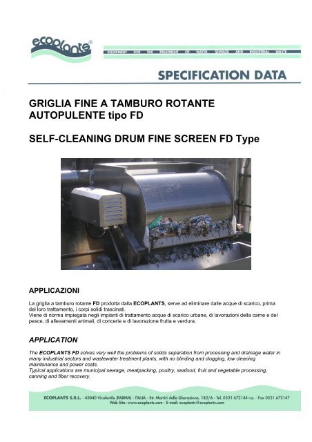
APPLICAZIONI<br />
La griglia a tamburo rotante <strong>FD</strong> prodotta dalla ECOPLANTS, serve ad eliminare dalle acque di scarico, prima<br />
del loro trattamento, i corpi solidi trascinati.<br />
Viene di norma impiegata negli impianti di trattamento acque di scarico urbane, di lavorazioni della carne e del<br />
pesce, di allevamenti animali, di concerie e di lavorazione frutta e verdura.<br />
APPLICATION<br />
The ECOPLANTS <strong>FD</strong> solves very well the problems of solids separation from processing and drainage water in<br />
many industrial sectors and wastewater treatment plants, with no blinding and clogging, low cleaning<br />
maintenance and power costs.<br />
Typical applications are municipal sewage, meatpacking, poultry, seafood, fruit and vegetable processing,<br />
canning and fiber recovery.
ELEMENTO <strong>GRIGLIA</strong>NTE<br />
Il cilindro, elemento fondamentale dell’unità, è realizzato completamente in Aisi 304.<br />
L’elemento grigliante è costituito da un cilindro, realizzato con un filo trapezoidale avvolto ad elica su una<br />
struttura di supporto, con spazi liberi da 0,25 a 3,0 mm, a seconda dei solidi da separare.<br />
SCREENING DEVICE<br />
The cylinder, completely made in AISI 304, is the unit heart.<br />
Wedge-shaped wire is wrapped around a support structure to form a helical coil, with free spaces from 0.25 to<br />
3,0 mm. according to solids to be separated.<br />
DESCRIZIONE E<br />
FUNZIONAMENTO<br />
La griglia a tamburo rotante <strong>FD</strong> è costruita in<br />
acciaio inossidabile AISI 304.La costruzione<br />
dell’<strong>FD</strong> è veramente semplice.<br />
Le sole parti in movimento sono: una griglia<br />
cilindrica, un riduttore ed un motore.<br />
Gli altri componenti principali sono:<br />
- una vasca d’alimentazione che smorza il<br />
flusso affluente e lo distribuisce sopra la<br />
griglia cilindrica<br />
- una lama raschiatrice per la rimozione dei<br />
solidi<br />
- un set di tenute tra il cilindro e la struttura<br />
Il liquido da trattare è introdotto nella vasca<br />
d’alimentazione che rallenta la sua velocità e<br />
lo distribuisce contro il cilindro rotante di<br />
grigliatura.<br />
I solidi sono trattenuti sulla superficie esterna<br />
del tamburo e sono rimossi dalla lama raschiatrice.<br />
Il liquido così ripulito, attraversa poi per gravità il tamburo, dall’interno verso l’esterno, e si raccoglie nella<br />
vasca di raccolta sottostante munita di attacco flangiato nel modello <strong>FD</strong> o con fondo aperto nel modello<br />
<strong>FD</strong>/SA per canale.<br />
Durante l’attraversamento del tamburo, il liquido ripulisce le fenditure eventualmente intasate.<br />
La motorizzazione standard è realizzata con motoriduttore.<br />
Se necessario, è possibile modificare la velocità di rotazione del cilindro sostituendo il motore con un altro a<br />
differente polarità.<br />
Se è richiesta una variazione continua della velocità, può essere fornito un variatore.<br />
Queste griglie sono fornite, di serie, con un TROPPO PIENO REGOLABILE al fine di poter regolare nel<br />
migliore dei modi la portata di alimentazione.<br />
Su richiesta la ECOPLANTS è in grado di realizzare griglie particolari, con ingombri ed attacchi diversi dallo<br />
standard, con accessori speciali ed anche in AISI 316.<br />
Fd2
<strong>FD</strong> CON COMPATTATORE A COCLEA<br />
<strong>FD</strong> WITH SPIRAL PRESS<br />
DESCRIPTION AND OPERATION<br />
VERSIONI SPECIALI<br />
SPECIAL TYPE<br />
The unit is made in AISI 304 stainless steel. The <strong>FD</strong> construction is very simple.<br />
The only moving parts are: cylindrical screen, gear reducer and motor.<br />
The other main components are:<br />
- head-box which baffles the influent and distributes it over the screen<br />
- doctor blade for solids removal<br />
- set of seals between the cylinder and the structure<br />
<strong>FD</strong> CON PULIZIA A SPAZZOLA <strong>ROTANTE</strong><br />
<strong>FD</strong> CLEANING BY ROTATING BRUSH<br />
The influent to be screened is introduced into the head-box which slows down the flow and distributes it into the<br />
rotating cylindrical screen.<br />
The solids are retained on the outside screen surface and removed by the doctor blade. The screen effluent<br />
passes again through the cylinder bottom from inside to outside and it is collected into suitable collecting base<br />
(<strong>FD</strong> type). The unit without the collecting base can be directly fitted on channels or pumping stations (<strong>FD</strong>/SA<br />
type). This screened water, during the free fall through the cylinder, carries on an efficacious backwashing of the<br />
screen openings. In this way the portion of the cylinder screen to be fed is always perfectly cleaned and there is<br />
not mucilage formation inside the cylindrical screen.<br />
Motorization standard system, is a gear reducer unit. If necessary, it is possible to modify the cylinder speed<br />
rotation by replacing the motor with another one having different polarity. If a continuous speed variation is<br />
required, a variator can be supplied.<br />
In order to have the best feed capacity, these screens are standard supplied, with a an adjustable OVERFLOW.<br />
According to utilizer’s requirements, screens in AISI 316, overall dimensions and attaching points different from<br />
standard, can be manufactured by ECOPLANTS.<br />
Fd2
COME LAVORA – HOW IT WORKS<br />
Fd2
CARATTERISTICHE TECNICHE<br />
- Luce tra le barre mm<br />
- Potenza installata kW<br />
- Velocità di rotazione con motoriduttore giri/min<br />
- Velocità di rotazione con motovariatore giri/min<br />
TECHNICAL DATA<br />
- Cylinder opening sizes mm<br />
- Eng. power kW<br />
- Cylinder speed with gearmotor rpm<br />
- Cylinder speed with motor variator rpm<br />
PORTATE / FLOW CAPACITIES<br />
Modello<br />
Type<br />
0,25 – 3,0<br />
0,18 – 0,75<br />
9<br />
3 – 17<br />
0,25 – 3,0<br />
0,18 – 0,75<br />
9<br />
3 – 17<br />
Luci di passaggio in mm – Opening sizes in mm<br />
0,25 0,50 0,75 1,00 1,25 1,50 2,00 2,50 3,00<br />
Portata in m3/h (valori indicativi per acque di scarico urbane con contenuto in solidi sospesi max di 200 mg/l)<br />
Flow capacity in m3/h (approximate values for civil wastewater which have a max. suspended solids level of 200 mg/l)<br />
15/A 8 13 16 19 21 23 25 27 28<br />
30/A 15 25 32 38 42 45 50 54 57<br />
60/C 29 50 67 80 91 100 115 125 134<br />
120/C 57 100 134 160 182 201 229 251 267<br />
180 86 150 201 241 274 301 344 376 401<br />
200 96 167 223 267 304 334 382 418 446<br />
240 115 201 267 321 365 401 459 501 535<br />
300 143 251 334 401 456 501 573 627 669<br />
360 172 301 401 481 547 602 688 752 802<br />
400 191 334 446 535 608 669 764 836 892<br />
460 220 384 513 615 699 769 879 961 1025<br />
600 270 490 672 826 958 1072 1259 1407 1526<br />
750 337 612 840 1033 1198 1340 1574 1758 1907<br />
900 405 735 1009 1240 1437 1608 1889 2110 2289<br />
Fd2
DIMENSIONI / DIMENSION (mm)<br />
<strong>FD</strong> Type<br />
<strong>FD</strong> Type 15A 30A 60C 120C 180 200 240 300 360 400 460<br />
Drum diameter 300 300 630 630 630 630 630 630 630 630 630<br />
Drum length 400 800 300 600 900 1000 1200 1500 1800 2000 2300<br />
Eng. Power (kW) 0,18 0,18 0,37 0,37 0,37 0,37 0,37 0,37 0,37 0,37 0,37<br />
A 690 690 1265 1265 1265 1265 1265 1265 1265 1265 1265<br />
B 745 745 1150 1150 1150 1150 1150 1150 1150 1150 1150<br />
C 690 1090 690 990 1290 1390 1590 1890 2190 2390 2690<br />
i 65 80 125 200 200 250 250 300 300 300 350<br />
t 50 65 100 150 150 200 200 250 250 250 300<br />
s 80 100 250 250 250 300 300 350 400 400 450<br />
Hi 410 410 850 850 850 850 850 850 850 850 850<br />
Ht 525 525 1095 1095 1095 1095 1095 1095 1095 1095 1095<br />
Hs 135 145 205 260 260 285 285 300 325 325 350<br />
L 290 290 500 500 500 500 500 500 500 500 500<br />
CONNESSIONI FLANGIATE UNI 2304 PN 10 – UNI 2304 PN 10 FLANGED CONNECTIONS<br />
Fd2
<strong>FD</strong>SA Type<br />
<strong>FD</strong>/SA Type 15A 30A 60C 120C 180 200 240 300 360 400 460 600 750 900<br />
Drum diameter 300 300 630 630 630 630 630 630 630 630 630 915 915 915<br />
Drum length 400 800 300 600 900 1000 1200 1500 1800 2000 2300 2000 2500 3000<br />
Eng. Power (kW) 0,18 0,18 0,37 0,37 0,37 0,37 0,37 0,37 0,37 0,37 0,37 0,75 0,75 0,75<br />
A 395 395 765 765 765 765 765 765 765 765 765 1130 1130 1130<br />
B 745 745 1150 1150 1150 1150 1150 1150 1150 1150 1150 1710 1710 1710<br />
C 690 1090 690 990 1290 1390 1590 1890 2190 2390 2690 2220 2720 3220<br />
i 65 80 125 200 200 250 250 300 300 300 350 2x300 2x300 2x350<br />
t 50 65 100 150 150 200 200 250 250 250 300 300 300 350<br />
Hi 120 120 350 350 350 350 350 350 350 350 350 490 490 490<br />
Ht 235 235 595 595 595 595 595 595 595 595 595 840 840 840<br />
CONNESSIONI FLANGIATE UNI 2304 PN 10 – UNI 2304 PN 10 FLANGED CONNECTIONS<br />
Fd2
<strong>FD</strong>/SA 900 TYPE<br />
MOTORIZZAZIONE / DRIVE SYSTEM<br />
Fd2