Quick Start Owner's Manual Manual de inicio rápido para el usuario ...
Quick Start Owner's Manual Manual de inicio rápido para el usuario ...
Quick Start Owner's Manual Manual de inicio rápido para el usuario ...

Create successful ePaper yourself
Turn your PDF publications into a flip-book with our unique Google optimized e-Paper software.
<strong>Quick</strong> <strong>Start</strong> Owner’s <strong>Manual</strong><br />
USB Turntable<br />
(TTUSB)<br />
<strong>Manual</strong> <strong>de</strong> <strong>inicio</strong> <strong>rápido</strong> <strong>para</strong> <strong>el</strong> <strong>usuario</strong> (ESPAÑOL)<br />
Gebrauchsanweisung zur schn<strong>el</strong>len Inbetriebnahme<br />
(DEUTSCH)<br />
Gui<strong>de</strong> d’utilisation rapi<strong>de</strong> (FRANÇAIS)<br />
<strong>Manual</strong>e Rapido di Utilizzazione (ITALIANO)<br />
Box Contents
(ENGLISH) QUICK START GUIDE<br />
o Make sure all items listed on the front of this gui<strong>de</strong> are<br />
inclu<strong>de</strong>d in the box.<br />
o READ SAFETY INSTRUCTION BOOKLET BEFORE USING<br />
THE PRODUCT<br />
o Go to http://www.ion-audio.com for product registration.<br />
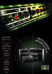
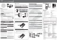
GENERAL CONTROLS<br />
1. Power Cable: This power cable should be plugged into a wall<br />
receptacle AFTER all audio connections are ma<strong>de</strong>.<br />
2. RCA Audio Output Cables: These cables should be plugged<br />
into a CD or Auxiliary input on your computer. IMPORTANT:<br />
There is a switch on the bottom pan<strong>el</strong>, next to the RCA cables<br />
that s<strong>el</strong>ects between PHONO/LINE. Use PHONO lev<strong>el</strong> for<br />
plugging into a turntable input on a home stereo. Use the LINE<br />
lev<strong>el</strong> for plugging into CD/AUX/TAPE inputs. WARNING: You<br />
may damage your receiver if you plug in a LINE lev<strong>el</strong><br />
into a PHONO input.<br />
2
3. USB Audio Output: Use the inclu<strong>de</strong>d USB Cable to connect<br />
your turntable to your computer. Refer to the software<br />
instruction gui<strong>de</strong> before plugging in your turntable.<br />
4. Power Button: This ring around the power button illuminates<br />
red when the turntable is switched on.<br />
5. Platter: This platter must be secur<strong>el</strong>y fastened to the<br />
turntable prior to operation. The Motor Drive B<strong>el</strong>t can be found<br />
on the drive ring un<strong>de</strong>rneath the platter. See SETUP<br />
INSTRUCTIONS for <strong>de</strong>tailed information on installing the Motor<br />
Drive B<strong>el</strong>t.<br />
6. <strong>Start</strong>/Stop Buttons: These buttons start and stop the<br />
turntable motor. Both buttons have the same function. If they<br />
seem to not be functioning, check to make sure that the Motor<br />
Drive B<strong>el</strong>t is properly installed in the SETUP INSTRUCTIONS.<br />
7. 1/8” Stereo Line Input: Connect Tape Players, Re<strong>el</strong> to Re<strong>el</strong>,<br />
or any other audio source here. This signal is sent to the<br />
computer through the USB. Make sure that your phono<br />
cartridge is installed while using this input for maximum<br />
sound quality. Also make sure that your RCA jacks are either<br />
plugged into an input <strong>de</strong>vice or not in contact with metal.<br />
Note: The 1/8" audio input is not routed to the turntable's RCA<br />
output jacks, only to your computer via USB.<br />
8. 33 and 45 RPM Buttons: These buttons control the RPM of<br />
the turntable platter. A red LED indicates which RPM mo<strong>de</strong> has<br />
been s<strong>el</strong>ected.<br />
NOTE: If the turntable is powered down while in the 45 RPM<br />
setting, it will return to 33 RPM when it is powered up.<br />
Note: You can record your 78RPM records by recording them<br />
at 33 or 45rpm, then changing them to 78 in the Audacity<br />
software.<br />
9. Pitch LED: This LED illuminates green when the pitch sli<strong>de</strong>r is<br />
set at 0%. When the pitch sli<strong>de</strong>r is moved away from zero, the<br />
LED illuminates red.<br />
10. Pitch Sli<strong>de</strong>r: This sli<strong>de</strong> control allows the pitch to be increased<br />
or <strong>de</strong>creased by 10%. In the center position the pitch is at 0%.<br />
When moved away from the center and towards the tone arm<br />
<strong>de</strong>creases the pitch (slows down the platter) and moving the<br />
pitch sli<strong>de</strong>r away from the tone arm increase the pitch (speeds<br />
up the platter.)<br />
TONE ARM: Items 11 – 15 are all parts of the tonearm. Refer<br />
to the TONEARM SETUP section for additional <strong>de</strong>tails on these<br />
controls. Your mo<strong>de</strong>l will be equipped with straight arm or Sarm<br />
style <strong>de</strong>pending upon mo<strong>de</strong>l purchased.<br />
3
11. Counter Weight and Scale Ring: The Counterweight is used<br />
to balance the head sh<strong>el</strong>l and cartridge assembly so that the<br />
proper amount of stylus pressure is applied to the record.<br />
12. Anti-Skate Adjustment: This knob is used to compensate for<br />
inward tracking forces. See TONEARM SETUP for more <strong>de</strong>tails.<br />
13. Arm Clip: This specially <strong>de</strong>signed arm clip secures the tone<br />
arm while at rest or when not in use. The arm clip has been<br />
<strong>de</strong>signed to remain in the up position while unlocked.<br />
NOTE: When transporting the turntable, it is always<br />
recommen<strong>de</strong>d that the headsh<strong>el</strong>l be removed and the arm clip<br />
secured to prevent tonearm or turntable damage.<br />
14. Tone Arm Lock Nut: This Aluminum nut is used to secure the<br />
head sh<strong>el</strong>l and cartridge assembly to the tone arm tube. See<br />
Cartridge Setup for more <strong>de</strong>tails.<br />
15. Cartridge and Headsh<strong>el</strong>l: The cartridge is pre-mounted on a<br />
standard headsh<strong>el</strong>l. The cartridge is user replaceable and<br />
compatible with a variety of standard cartridges. Be sure to<br />
remove the clear plastic cover before operating the turntable<br />
from the cartridge.<br />
PLATTER SETUP<br />
WARNING: Incorrect Platter setup can lead to poor turntable<br />
performance, platter instability or permanent motor damage.<br />
1. <strong>Start</strong> by placing the rubber drive b<strong>el</strong>t around the inner bottom<br />
ring of the turntable platter. This should come preinstalled, but<br />
check to make sure that it is not twisted or damaged.<br />
2. Install the Platter on the center spindle and press it down<br />
firmly. Check to make sure that it rotates uniformly and does<br />
not wobble excessiv<strong>el</strong>y.<br />
3. Rotate the platter so that the one of the holes is aligned with<br />
the <strong>Start</strong> Stop button on the front corner of the turntable. The<br />
brass motor spindle should be visible through this hole.<br />
4. Reach into the hole and pull the rubber drive b<strong>el</strong>t off of the<br />
inner ring, and install it over the motor spindle. Be careful not<br />
to twist the rubber drive b<strong>el</strong>t during this step. Check to make<br />
sure the platter rotates uniformly. If the drive b<strong>el</strong>t is properly<br />
installed, there should be a slight amount of tension that<br />
brings the platter to a stop after spinning it fre<strong>el</strong>y.<br />
4
TONEARM SETUP<br />
1. Begin by rotating the counterweight clockwise until it is in the<br />
complete forward position (NOTE: this is also the maximum<br />
amount of pressure that can be applied to the cartridge.)<br />
2. Now there should be a fe<strong>el</strong>ing of weight and resistance when<br />
the head sh<strong>el</strong>l is raised and lowered. Begin rotating the<br />
counterweight counter-clockwise (away from the pivot point)<br />
until the weight and resistance fe<strong>el</strong>ing is gone. If done<br />
properly, the tone arm will pivot with very little resistance back<br />
and forth indicating that there is exactly 0 grams of stylus<br />
pressure.<br />
3. With the counterweight in its new position further away from<br />
tone arm pivot point, grasp the scale ring of the counter<br />
weight and rotate it until "0" is in the vertical position.<br />
4. Finally, rotate the counterweight (and scale ring) clockwise<br />
(towards the pivot point) until the <strong>de</strong>sired amount of weight is<br />
reached. If the scale rotates 360 <strong>de</strong>grees beyond the zero<br />
point, the new scale ring reading should be ad<strong>de</strong>d to 3.5.<br />
*The inclu<strong>de</strong>d head sh<strong>el</strong>l and cartridge assembly requires a<br />
minimum of 3 grams and no more than 5 grams for optimum<br />
performance.<br />
5
Setting the Anti-Skate Adjustment<br />
In most cases, the Anti-Skate should be set to its minimum<br />
setting. Anti-Skate compensates for inward tracking forces that<br />
occur with certain cartridges when the stylus nears the center of<br />
the record. If the turntable is experiencing excessive skipping<br />
during back-cueing and scratching while nearing the center<br />
spindle, try increasing the Anti-Skate in the increments indicated<br />
on the dial. <strong>Start</strong> by adding an increment of 1, test its<br />
performance, than increase it more, and so on.<br />
IMPORTANT<br />
Make sure that the f<strong>el</strong>t slipmat is always placed on top of the<br />
platter while using the turntable. Failure to use the slipmat may<br />
cause damage to your media as w<strong>el</strong>l as damage to the turntable.<br />
Remove the plastic cartridge cover (needle cover) before<br />
operating the turntable.<br />
BEFORE RETURNING THE PRODUCT, please contact Numark<br />
Industries or your retailer for technical support. Contact<br />
information can be found in the Safety Instruction Booklet<br />
inclu<strong>de</strong>d with this product.<br />
6
(ESPAÑOL) MANUAL DE COMIENZO RÁPIDO DEL LECTOR<br />
1. Asegúrese <strong>de</strong> que todos los artículos incluidos al <strong>inicio</strong> <strong>de</strong> este manual están incluidos en la caja.<br />
2. LEA LAS INSTRUCCIONES DEL FOLLETO DE SEGURIDAD ANTES DE UTILIZAR EL PRODUCTO.<br />
3. Visite http://www.ion-audio.com <strong>para</strong> registrar <strong>el</strong> producto.<br />
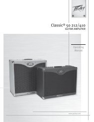
CONTROLES GENERALES<br />
1. Cable <strong>de</strong> alimentación:<br />
Este cable <strong>de</strong> alimentación<br />
<strong>de</strong>be ser enchufado a una<br />
toma <strong>de</strong> corriente en la<br />
pared DESPUÉS <strong>de</strong> que se<br />
realicen todas las conexiones<br />
<strong>de</strong> audio.<br />
2. Cables RCA <strong>de</strong> salida <strong>de</strong><br />
audio: Estos cables se<br />
<strong>de</strong>ben enchufar a una unidad<br />
<strong>de</strong> CD o entrada auxiliar <strong>de</strong><br />
su computadora.<br />
IMPORTANTE: Hay un<br />
conmutador en <strong>el</strong> pan<strong>el</strong><br />
inferior, junto a los cables<br />
RCA, que s<strong>el</strong>ecciona entre<br />
PHONO y LINE (Fonográfico<br />
y Línea). Use <strong>el</strong> niv<strong>el</strong><br />
fonográfico <strong>para</strong> enchufar en<br />
la entrada <strong>de</strong> giradiscos <strong>de</strong><br />
un estéreo hogareño. Use <strong>el</strong><br />
niv<strong>el</strong> <strong>de</strong> línea <strong>para</strong> enchufar<br />
a entradas CD/AUX/TAPE.<br />
ADVERTENCIA: Pue<strong>de</strong> dañar<br />
<strong>el</strong> receptos si enchufa <strong>el</strong><br />
niv<strong>el</strong> <strong>de</strong> línea en una entrada<br />
fonográfica.<br />
3. Salida <strong>de</strong> audio USB: Use<br />
<strong>el</strong> cable USB incluido <strong>para</strong><br />
conectar su giradiscos a su<br />
computadora. Consulte la guía <strong>de</strong> instrucciones <strong>de</strong> software antes <strong>de</strong> enchufar <strong>el</strong> giradiscos.<br />
4. Botón <strong>de</strong> alimentación: Este anillo alre<strong>de</strong>dor <strong>de</strong>l botón <strong>de</strong> alimentación se ilumina <strong>de</strong> color rojo cuando se<br />
encien<strong>de</strong> <strong>el</strong> giradiscos.<br />
5. Plato: Este plato <strong>de</strong>be estar bien ajustado al giradiscos antes <strong>de</strong> hacerlo funcionar. La correa <strong>de</strong> transmisión <strong>de</strong>l<br />
motor pue<strong>de</strong> ubicarse en <strong>el</strong> anillo <strong>de</strong>l drive, <strong>de</strong>bajo <strong>de</strong>l plato. Vea las INSTRUCCIONES DE INSTALACIÓN <strong>para</strong> más<br />
información sobre la instalación <strong>de</strong> la Correa <strong>de</strong> transmisión <strong>de</strong>l motor.<br />
6. Botones <strong>Start</strong>/Stop: Estos botones ponen en marcha y <strong>de</strong>tienen <strong>el</strong> motor <strong>de</strong>l giradiscos. Ambos botones tienen<br />
la misma función. Si parecen no funcionar, revise las INSTRUCCIONES DE INSTALACIÓN <strong>para</strong> asegurarse <strong>de</strong> que la<br />
correa <strong>de</strong> transmisión <strong>de</strong>l motor está instalada correctamente.<br />
7. Entrada <strong>de</strong> línea estéreo <strong>de</strong> 1/8”: Pue<strong>de</strong> conectar aquí reproductores <strong>de</strong> casetes y cintas o cualquier otra<br />
fuente <strong>de</strong> audio. Esta señal se envía a la computadora por <strong>el</strong> USB. Asegúrese <strong>de</strong> que su cápsula fonográfica esté<br />
instalada cuando usa esta entrada, <strong>para</strong> lograr la máxima calidad <strong>de</strong>l sonido. Asegúrese también <strong>de</strong> que sus jacks<br />
RCA estén enchufados a un dispositivo <strong>de</strong> entrada o que no estén en contacto con partes metálicas. Nota: La<br />
entrada <strong>de</strong> audio <strong>de</strong> 1/8" no se encamina a los conectores <strong>de</strong> salida RCA <strong>de</strong>l giradiscos, sino sólo a su<br />
computadora mediante USB.<br />
8. Botones <strong>de</strong> 33 y 45 RPM (revoluciones por minuto): Estos botones controlan las RPM <strong>de</strong>l plato <strong>de</strong>l giradiscos.<br />
Un LED rojo indica <strong>el</strong> modo <strong>de</strong> RPM que ha sido s<strong>el</strong>eccionado.<br />
NOTA: Si apaga <strong>el</strong> giradiscos mientras que está funcionando a 45 RPM, volverá a las 33 RPM cuando<br />
encienda <strong>de</strong> nuevo <strong>el</strong> giradiscos.<br />
9. LED <strong>de</strong>l Pitch: Este LED se ilumina <strong>de</strong> color ver<strong>de</strong> cuando <strong>el</strong> <strong>de</strong>slizador <strong>de</strong>l pitch está fijado al 0%. Cuando <strong>el</strong><br />
<strong>de</strong>slizador <strong>de</strong>l pitch es alejado <strong>de</strong>l cero, <strong>el</strong> LED se ilumina <strong>de</strong> color rojo.<br />
10. Deslizador <strong>de</strong>l Pitch: Este <strong>de</strong>slizador permite aumentar o disminuir <strong>el</strong> pitch en un 10%. En la posición central, <strong>el</strong><br />
pitch está al 0%. Cuando es alejado <strong>de</strong>l centro y se mueve hacia <strong>el</strong> brazo, esto disminuye <strong>el</strong> pitch (baja la<br />
v<strong>el</strong>ocidad <strong>de</strong>l plato) y cuando <strong>el</strong> <strong>de</strong>slizador <strong>de</strong>l pitch es alejado <strong>de</strong>l brazo, esto hace que aumente <strong>el</strong> pitch<br />
(aumenta la v<strong>el</strong>ocidad <strong>de</strong>l plato.)<br />
EL BRAZO: Los artículos 11 – 15 forman todos parte <strong>de</strong>l brazo. Consulte la sección INSTALACIÓN DEL BRAZO <strong>para</strong> más<br />
<strong>de</strong>talles sobre estos controles. Su mo<strong>de</strong>lo estará equipado con un brazo recto o un brazo en forma <strong>de</strong> S, <strong>de</strong>pendiendo <strong>de</strong>l<br />
mo<strong>de</strong>lo adquirido.<br />
11. Contrapeso y anillo numerado: El contrapeso se usa <strong>para</strong> balancear <strong>el</strong> ensamblaje <strong>de</strong>l portacápsulas y <strong>de</strong>l<br />
cartucho con <strong>el</strong> fin <strong>de</strong> aplicarle al disco la cantidad a<strong>de</strong>cuada <strong>de</strong> presión <strong>de</strong> la aguja.<br />
12. Ajuste Anti-Skate (anti-<strong>de</strong>slizamiento): Este botón se usa <strong>para</strong> compensar por las fuerzas <strong>de</strong> tracción <strong>de</strong><br />
entrada. Consulte la INSTALACIÓN DEL BRAZO <strong>para</strong> más <strong>de</strong>talles.<br />
13. Clip <strong>de</strong>l brazo: Este clip está diseñado especialmente <strong>para</strong> fijar <strong>el</strong> brazo mientras está en <strong>el</strong> soporte o mientras no<br />
se usa. El clip ha sido diseñado <strong>para</strong> permanecer hacia arriba mientras no esté fijado.<br />
NOTA: Al transportar <strong>el</strong> giradiscos, es siempre recomendable retirar <strong>el</strong> portacápsulas y sujetar con firmeza <strong>el</strong> clip<br />
<strong>de</strong>l brazo <strong>para</strong> evitar daños al brazo o al giradiscos.<br />
14. Tuerca <strong>de</strong> fijación <strong>de</strong>l brazo: Esta tuerca <strong>de</strong> aluminio se usa <strong>para</strong> fijar <strong>el</strong> ensamblaje <strong>de</strong>l portacápsulas y <strong>de</strong>l<br />
cartucho al tubo <strong>de</strong>l brazo. Consulte la Instalación <strong>de</strong>l cartucho <strong>para</strong> más <strong>de</strong>talles.<br />
15. Cápsula y portacápsulas: La cápsula está preinstalada en un portacápsulas estándar. La cápsula es<br />
reemplazable por <strong>el</strong> <strong>usuario</strong> y compatible con una variedad <strong>de</strong> cápsulas estándar. Asegúrese <strong>de</strong> retirar la cubierta<br />
plástica transparente antes <strong>de</strong> hacer funcionar <strong>el</strong> giradiscos con la cápsula.<br />
7
INSTALACIÓN DEL PLATO<br />
ADVERTENCIA: La instalación incorrecta <strong>de</strong>l plato pue<strong>de</strong> tener como consecuencia un mal rendimiento <strong>de</strong>l<br />
giradiscos, una inestabilidad <strong>de</strong>l plato o un daño permanente al motor.<br />
1. Comience la instalación colocando la correa <strong>de</strong> transmisión <strong>de</strong> goma alre<strong>de</strong>dor <strong>de</strong>l anillo inferior <strong>de</strong>l centro <strong>de</strong>l<br />
plato <strong>de</strong>l giradiscos. Esto <strong>de</strong>bería estar preinstalado, pero revís<strong>el</strong>o <strong>para</strong> asegurarse <strong>de</strong> que no está doblado o<br />
dañado.<br />
2. Instale <strong>el</strong> plato en <strong>el</strong> eje central y presión<strong>el</strong>o firmemente. Revís<strong>el</strong>o <strong>para</strong> asegurarse <strong>de</strong> que gira <strong>de</strong> modo uniforme<br />
y <strong>de</strong> que no tambalea excesivamente.<br />
3. Gire <strong>el</strong> plato <strong>para</strong> que uno <strong>de</strong> los agujeros esté alineado con <strong>el</strong> botón <strong>Start</strong>/Stop en la esquina anterior <strong>de</strong>l<br />
giradiscos. El eje <strong>de</strong> latón <strong>de</strong>l motor <strong>de</strong>bería ser visible a través <strong>de</strong> este agujero.<br />
4. Inserte la mano en <strong>el</strong> agujero y tire la correa <strong>de</strong> transmisión <strong>de</strong> goma <strong>de</strong>l anillo interior, e instál<strong>el</strong>a sobre <strong>el</strong> eje <strong>de</strong>l<br />
motor. Tenga cuidado <strong>de</strong> no doblar la correa <strong>de</strong> transmisión <strong>de</strong> goma durante este proceso. Compruebe que <strong>el</strong><br />
plato gira <strong>de</strong> modo uniforme. Si la correa <strong>de</strong> transmisión está bien instalada, <strong>de</strong>bería haber algo <strong>de</strong> tensión que<br />
<strong>de</strong>tuviese <strong>el</strong> plato <strong>de</strong>spués <strong>de</strong> girar libremente.<br />
INSTALACIÓN DEL BRAZO<br />
1. Comience por girar <strong>el</strong> contrapeso en <strong>el</strong> sentido <strong>de</strong> las agujas <strong>de</strong>l r<strong>el</strong>oj hasta que esté completamente en posición<br />
hacia <strong>de</strong>lante (NOTA: esta es también la máxima cantidad <strong>de</strong> presión que se le pue<strong>de</strong> aplicar al cartucho.)<br />
2. Ahora <strong>de</strong>bería haber una sensación <strong>de</strong> peso y resistencia al levantar o bajar <strong>el</strong> portacápsulas. Comience a girar <strong>el</strong><br />
contrapeso en <strong>el</strong> sentido contrario a las agujas <strong>de</strong>l r<strong>el</strong>oj (alejándolo <strong>de</strong>l punto <strong>de</strong> giro) hasta que la sensación <strong>de</strong><br />
peso y resistencia <strong>de</strong>saparezca. Si esto se hace correctamente, <strong>el</strong> brazo girará <strong>de</strong> un lado al otro con muy poca<br />
resistencia indicando que hay exactamente 0 gramos <strong>de</strong> presión sobre la aguja.<br />
3. Con <strong>el</strong> contrapeso en su nueva posición, más alejado <strong>de</strong>l punto <strong>de</strong> giro <strong>de</strong>l brazo, tome <strong>el</strong> anillo numerado <strong>de</strong>l<br />
contrapeso y gír<strong>el</strong>o hasta que <strong>el</strong> “0” esté en la posición vertical.<br />
4. Finalmente, gire <strong>el</strong> contrapeso (y <strong>el</strong> anillo numerado) en <strong>el</strong> sentido <strong>de</strong> las agujas <strong>de</strong>l r<strong>el</strong>oj (hacia <strong>el</strong> punto <strong>de</strong> giro)<br />
hasta que alcance <strong>el</strong> peso <strong>de</strong>seado. Si <strong>el</strong> anillo numerado gira 360 grados más <strong>de</strong>l punto cero, la nueva cantidad<br />
<strong>de</strong>l anillo numerado <strong>de</strong>bería ser agregada a los 3.5.<br />
*El ensamblaje <strong>de</strong>l portacápsulas y <strong>de</strong>l cartucho que se incluye aquí, requiere un mínimo <strong>de</strong> 3 gramos y un<br />
máximo <strong>de</strong> 5 gramos <strong>para</strong> un rendimiento óptimo.<br />
Ajuste <strong>de</strong>l Anti-Skate (anti-<strong>de</strong>slizamiento)<br />
En la mayoría <strong>de</strong> los casos, <strong>el</strong> Anti-Skate <strong>de</strong>bería ser ajustado al mínimo. El anti-skate compensa por las fuerzas <strong>de</strong><br />
tracción <strong>de</strong> entrada que ocurren con ciertos cartuchos cuando la aguja se acerca al centro <strong>de</strong>l disco. Si <strong>el</strong> giradiscos<br />
experimenta excesivos saltos en los retrocesos <strong>rápido</strong>s y rayados cuando se acerca al eje central, intente aumentar <strong>el</strong><br />
Anti-Skate en los incrementos indicados en <strong>el</strong> botón. Comience agregando un incremento <strong>de</strong> 1, pruebe su rendimiento y<br />
aumént<strong>el</strong>o más, y continúe así.<br />
8
(DEUTSCH) Schn<strong>el</strong>ler <strong>Start</strong><br />
1. Versichern Sie sich, daß alle im Anfang dieser Anleitung aufgeführten Teile in <strong>de</strong>r Schacht<strong>el</strong> enthalten sind.<br />
2. LESEN SIE DIE SICHERHEITSBROSCHÜRE BEVOR SIE DAS GERÄT BENUTZEN<br />
3. Um das Produkt zu registrieren, besuchen Sie bitte http://www.ion-audio.com.<br />
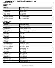
ALLGEMEINE BEDIENELEMENTE<br />
1. Stromkab<strong>el</strong>: Das Stromkab<strong>el</strong> wird in<br />
eine Steckdose gesteckt, NACHDEM<br />
alle Tonanschlüsse erfolgt sind.<br />
2. RCA-Audioausgabekab<strong>el</strong>: Diese<br />
Kab<strong>el</strong> dienen zum Anschluß <strong>de</strong>s<br />
Plattenspi<strong>el</strong>ers an z.B. ein DJ-<br />
Mischpult, einen Verstärker o<strong>de</strong>r<br />
analoge Soundkartenanschlüsse eines<br />
PCs.<br />
WICHTIGER HINWEIS:<br />
Ein Umschalter an <strong>de</strong>r Anschlussseite<br />
ermöglicht <strong>de</strong>n Wechs<strong>el</strong> von Phono zu<br />
Line Betrieb. Wählen Sie RCA-Phono<br />
zum Anschluss an einen Phono-<br />
Eingang o<strong>de</strong>r RCA-Line zum Anschluss<br />
an einen Line/CD/AUX Eingang (eines<br />
Mischpultes, eines Verstärkers o<strong>de</strong>r<br />
PCs)<br />
WARNUNG: Sie könnten ihren<br />
Receiver/Verstärker beschädigen,<br />
wenn Sie <strong>de</strong>n iTTUSB im Line<br />
Betrieb an einen Phono Eingang<br />
anschließen!<br />
3. USB Audio Ausgang: Benutzen Sie das mitg<strong>el</strong>ieferte USB Kab<strong>el</strong> um <strong>de</strong>n Plattenspi<strong>el</strong>er mit ihrem Computer zu<br />
verbin<strong>de</strong>n. Der iTTUSB ist kompatib<strong>el</strong> zu USB 1 und USB 2 Anschlüssen. Weitere Hinweise zu <strong>de</strong>n System<br />
Einst<strong>el</strong>lung <strong>de</strong>r Software entnehmen Sie bitte <strong>de</strong>r Anleitung zur Software Installation (online auf www.ion-audio.<strong>de</strong><br />
„iTTUSB_Software_Audacity“)<br />
4. Ein/Ausschaltknopf: Der Ring um <strong>de</strong>n Ein/Aus-Schaltknopf leuchtet rot auf, wenn <strong>de</strong>r Plattenspi<strong>el</strong>er<br />
eingeschaltet ist.<br />
5. Plattent<strong>el</strong>ler: Dieser Dreht<strong>el</strong>ler muss vor Inbetriebnahme mit <strong>de</strong>m Plattenspi<strong>el</strong>er fest verbun<strong>de</strong>n sein. Der<br />
Motorantriebsriemen befin<strong>de</strong>t sich auf <strong>de</strong>m Antriebsring unterhalb <strong>de</strong>s Dreht<strong>el</strong>lers. Für Einz<strong>el</strong>heiten zur Installation<br />
<strong>de</strong>s Antriebsriemens lesen Sie bitte die AUFBAUANLEITUNG (auf <strong>de</strong>r folgen<strong>de</strong>n Seite).<br />
6. <strong>Start</strong>/Stop-Tasten: Diese Tasten starten und stoppen <strong>de</strong>n Plattenspi<strong>el</strong>ermotor. Bei<strong>de</strong> Tasten haben dies<strong>el</strong>be<br />
Funktion. Falls diese nicht zu funktionieren scheinen, st<strong>el</strong>len Sie mitt<strong>el</strong>s <strong>de</strong>r Aufbauanleitung sicher, dass <strong>de</strong>r<br />
Motorantriebsriemen korrekt installiert/montiert ist.<br />
7. Line in Audio-Eingang: Über diesen Line In Eingang (3,5 mm Stereo Miniklinke) können externe Geräte (z.B. ein<br />
Kassetten<strong>de</strong>ck) angeschlossen wer<strong>de</strong>n, und <strong>de</strong>ren Audiosignale ebenfalls über <strong>de</strong>n USB Audioausgang <strong>de</strong>s iTTUSB<br />
an <strong>de</strong>n Computer geführt wer<strong>de</strong>n.<br />
8. 33 und 45 RPM-Tasten: Diese Tasten steuern die Umdrehungsgeschwindigkeit <strong>de</strong>s Plattent<strong>el</strong>lers. Eine rote<br />
Leuchtdio<strong>de</strong> gibt an, w<strong>el</strong>che Umdrehungsgeschwindigkeit gewählt wur<strong>de</strong>.<br />
Hinweis: Beim Einschalten ist diese Umdrehungs-Einst<strong>el</strong>lung automatisch auf 33 RPM zurückgesetzt, auch<br />
wenn <strong>de</strong>r Plattenspi<strong>el</strong>er bei einer Einst<strong>el</strong>lung von 45 RPM ausgeschaltet wur<strong>de</strong>.<br />
9. Tonhöhen-Leuchtdio<strong>de</strong>: Diese Leuchtdio<strong>de</strong> leuchtet grün auf, wenn <strong>de</strong>r Tonhöhenregler auf 0% steht. Wenn <strong>de</strong>r<br />
Tonhöhenregler von 0 wegbewegt wird, leuchtet die Anzeige in rot auf.<br />
10. Tonhöhenregler: Mit diesem Schieberegler läßt sich die Tonhöhe bzw. die Geschwindigkeit um 10% erhöhen o<strong>de</strong>r<br />
vermin<strong>de</strong>rn. In <strong>de</strong>r mittleren St<strong>el</strong>lung ist die Tonhöhe bei 0%. Wenn <strong>de</strong>r Regler von <strong>de</strong>r Mitte in Richtung Tonarm<br />
bewegt wird, vermin<strong>de</strong>rt sich die Tonhöhe (Plattent<strong>el</strong>ler wird langsamer), wenn vom Tonarm weg bewegt wird,<br />
erhöht sich die Tonhöhe (Plattent<strong>el</strong>ler wird schn<strong>el</strong>ler.)<br />
TONARM: Die Punkte 11 – 15 sind alle Teile <strong>de</strong>s Tonarms. Für zusätzliche Einz<strong>el</strong>heiten über diese lesen Sie bitte im<br />
Abschnitt TONARM-AUFBAU nach. Abhängig vom gekauften Mo<strong>de</strong>ll ist Ihres entwe<strong>de</strong>r mit einem gera<strong>de</strong>n o<strong>de</strong>r S-förmigen<br />
Arm ausgerüstet.<br />
11. Gegengewicht und Skalenring: Das Gegengewicht dient dazu, die Headsh<strong>el</strong>l (Systemträger) mit <strong>de</strong>m<br />
Tonabnehmersystem so auszubalancieren, dass <strong>de</strong>r korrekte Na<strong>de</strong>ldruck auf die Schallplatte ausgeübt wird.<br />
12. Anti-Skate-Einst<strong>el</strong>lung: Dieser Drehknopf dient zum Ausgleich <strong>de</strong>r nach innen gerichteten Kräfte <strong>de</strong>s Tonarms.<br />
Für weitere Einz<strong>el</strong>heiten, lesen Sie bitte im Abschnitt TONARM-AUFBAU nach.<br />
13. Arm-Clip: Dieser spezi<strong>el</strong>l entworfene Arm-Clip sichert <strong>de</strong>n Tonarm während Pausen und bei Nichtgebrauch. Der<br />
Arm-Clip wur<strong>de</strong> so entworfen, dass er in <strong>de</strong>r aufrechten St<strong>el</strong>lung verbleibt solang er geöffnet ist.<br />
HINWEIS: Beim Transport <strong>de</strong>s Plattenspi<strong>el</strong>ers ist es immer empfehlenswert, das Headsh<strong>el</strong>l mit <strong>de</strong>m Tonabnehmer<br />
System zu entfernen und <strong>de</strong>n Arm-Clip zu verschliessen, um <strong>de</strong>n Tonarm o<strong>de</strong>r <strong>de</strong>n Plattenspi<strong>el</strong>er vor Beschädigung<br />
zu schützen.<br />
14. Tonarm-Verschluss: Diese Aluminiummutter dient zur festen Verbindung von Headsh<strong>el</strong>l-Systems mit <strong>de</strong>m<br />
Tonarm. Für weitere Einz<strong>el</strong>heiten, sehen Sie bitte unter Tonarm Aufbau nach.<br />
15. Headsh<strong>el</strong>l und Tonabnehmersystem: Das Tonabnehmersystem ist auf eine Standard-Headsh<strong>el</strong>l vormontiert.<br />
Sowohl das Tonabnehmersystem als auch die Na<strong>de</strong>l kann s<strong>el</strong>bst ausgetauscht wer<strong>de</strong>n und ist kompatib<strong>el</strong> zu allen<br />
Standard DJ Systemen. Vor <strong>de</strong>m ersten Gebrauch entfernen Sie die Plastik Schutzkappe vom System.<br />
9
AUFBAU DES PLATTENTELLERS<br />
WARNUNG: Unvorschriftsmäßiger Aufbau <strong>de</strong>s Plattent<strong>el</strong>lers kann zu schlechter Leistung <strong>de</strong>s Plattenspi<strong>el</strong>ers,<br />
Instabilität <strong>de</strong>s T<strong>el</strong>lers o<strong>de</strong>r zu permanentem Scha<strong>de</strong>n <strong>de</strong>s Motors führen.<br />
1. Zuerst legen Sie <strong>de</strong>n Gummi-Antriebsriemen um <strong>de</strong>n inneren unteren Ring <strong>de</strong>s Plattent<strong>el</strong>lers. Dies sollte bereits<br />
vorher installiert sein, aber überprüfen Sie, daß <strong>de</strong>r Riemen nicht verdreht o<strong>de</strong>r beschädigt ist.<br />
2. Setzen Sie <strong>de</strong>n T<strong>el</strong>ler auf die Zentralspin<strong>de</strong>l und drücken Sie ihn fest herunter. St<strong>el</strong>len Sie sicher, daß er rund läuft<br />
und nicht zuvi<strong>el</strong> Spi<strong>el</strong> hat.<br />
3. Drehen Sie <strong>de</strong>n T<strong>el</strong>ler so, daß eines <strong>de</strong>r Löcher mit <strong>de</strong>r <strong>Start</strong>/Stop-Taste an <strong>de</strong>r vor<strong>de</strong>ren Ecke <strong>de</strong>s Plattenspi<strong>el</strong>ers<br />
in einer Linie steht. Die Messingmotorspin<strong>de</strong>l sollte durch das Loch sichtbar sein.<br />
4. Greifen Sie in das Loch und ziehen Sie <strong>de</strong>n Gummiantriebsriemen vom inneren Ring über die Motorspin<strong>de</strong>l. Passen<br />
Sie auf, <strong>de</strong>n Gummiantriebsriemen dabei nicht zu verdrehen. St<strong>el</strong>len Sie sicher, daß <strong>de</strong>r Plattent<strong>el</strong>ler rund läuft.<br />
Wenn <strong>de</strong>r Antriebsriemen korrekt installiert ist, besteht eine leichte Spannung, w<strong>el</strong>che <strong>de</strong>n Dreht<strong>el</strong>ler zum Halt<br />
bringt nach<strong>de</strong>m er frei gedreht wur<strong>de</strong>.<br />
AUFBAU DES TONARMS<br />
1. Zuerst drehen Sie das Gegengewicht im Uhrzeigersinn, bis es sich vollständig in <strong>de</strong>r vor<strong>de</strong>rsten Position befin<strong>de</strong>t<br />
(HINWEIS: dies ist zugleich <strong>de</strong>r größtmögliche Druck, <strong>de</strong>r auf das Einsteckmodul ausgeübt wer<strong>de</strong>n darf.)<br />
2. Sie sollten nun Gewicht und Wi<strong>de</strong>rstand fühlen können, wenn das Kopfgehäuse angehoben und abgesenkt wird.<br />
Fangen Sie nun an, das Gegengewicht gegen <strong>de</strong>n Uhrzeigersinn (weg vom Schwenkpunkt) so lange zu drehen, bis<br />
das Gefühl von Gewicht und Wi<strong>de</strong>rstand nicht mehr wahrzunehmen sind. Falls dies genau ausgeführt wird,<br />
schwenkt <strong>de</strong>r Tonarm ohne großen Wi<strong>de</strong>rstand auf und ab, was be<strong>de</strong>utet, daß <strong>de</strong>r Druck auf <strong>de</strong>r Abtastna<strong>de</strong>l<br />
genau 0 Gramm beträgt.<br />
3. Mit <strong>de</strong>m Gegengewicht in <strong>de</strong>r neuen, vom Schwenkpunkt <strong>de</strong>s Tonarms weiter entfernten Position, drehen Sie <strong>de</strong>n<br />
Skalenring <strong>de</strong>s Gegengewichts solange, bis “0” in <strong>de</strong>r vertikalen Position steht.<br />
4. Zuletzt drehen Sie das Gegengewicht (und <strong>de</strong>n Skalenring) im Uhrzeigersinn (zum Schwenkpunkt hin) bis das<br />
gewünschte Gewicht erreicht ist. Falls die Skala sich mehr als 360 Grad über <strong>de</strong>n Nullpunkt hinaus dreht, sollte <strong>de</strong>r<br />
angezeigte neue Wert <strong>de</strong>s Skalenrings zu 3.5 dazuaddiert wer<strong>de</strong>n.<br />
*Das mitg<strong>el</strong>ieferte Kopfgehäuse und Einsteckmodul erfor<strong>de</strong>rn min<strong>de</strong>stens 3, jedoch höchstens 5 Gramm für<br />
optimale Leistung.<br />
Einst<strong>el</strong>lung <strong>de</strong>s Anti-Skate<br />
In <strong>de</strong>n meisten Fällen sollte das Anti-Skate auf seinen minimalsten Wert eingest<strong>el</strong>lt wer<strong>de</strong>n. Anti-Skate gleicht nach<br />
innen gerichtete Kräfte aus, w<strong>el</strong>che bei manchen Einsteckmodulen auftreten, wenn sich die Abtastna<strong>de</strong>l auf die<br />
Plattenmitte zubewegt. Falls beim Plattenspi<strong>el</strong>er während Back-Cueing und Scratching beim Zubewegen auf die<br />
Zentralspin<strong>de</strong>l außergewöhnlich starkes “Skipping” auftritt, versuchen Sie das Anti-Skate in <strong>de</strong>n auf <strong>de</strong>r Anzeige<br />
gezeigten Schritten zu erhöhen. Fangen Sie mit einer Steigerung von 1 an, testen Sie das Verhalten, dann steigern Sie es<br />
weiter, und so fort.<br />
10
(FRANÇAIS) GUIDE D’INSTALLATION RAPIDE<br />
1. Vous assurer que tous les articles énumérés au début <strong>de</strong> ce gui<strong>de</strong> sont inclus dans la boîte.<br />
2. LIRE LE LIVRET D’INSTRUCTION DE SÉCURITÉ AVANT DE FAIRE USAGE DU PRODUIT.<br />
3. Allez à http://www.ion-audio.com pour enregistrer le produit.<br />
COMMANDES GÉNÉRALES<br />
1. Câble d’alimentation : Ce<br />
câble d’alimentation doit être<br />
branché à une prise murale<br />
UNIQUEMENT après que tous<br />
les raccor<strong>de</strong>ments ont été<br />
effectués.<br />
2. Câbles stéréo RCA : Ces<br />
câbles doivent être branchés<br />
dans l’entrée pour lecteur <strong>de</strong><br />
cassettes ou auxiliaire <strong>de</strong><br />
votre ordinateur.<br />
IMPORTANT : Il y a un<br />
commutateur sur le panneau<br />
inférieur, à côté <strong>de</strong>s câbles<br />
RCA qui permet <strong>de</strong><br />
sélectionner entre une<br />
entrée phono ou ligne.<br />
Utiliser l'entrée PHONO pour<br />
brancher un tourne-disque à<br />
une chaîne stéréo. Utiliser<br />
l'entrée PHONO pour<br />
brancher à <strong>de</strong>s entrées pour<br />
lecteur <strong>de</strong> disques compacts,<br />
auxiliaires et cassette. MISE<br />
EN GARDE : Vous pourriez<br />
endommager votre<br />
récepteur si vous branchiez un câble à niveau ligne dans une entrée phono.<br />
3. Sortie audio USB : Branchez le tourne disque à votre ordinateur en utilisant le câble USB fourni. Veuillez<br />
consulter le gui<strong>de</strong> d’utilisation du logici<strong>el</strong> avant <strong>de</strong> brancher le tourne disque.<br />
4. Bouton d’alimentation : Le cercle autour du bouton d’alimentation <strong>de</strong>vient rouge lorsque la platine tournedisque<br />
est sous tension.<br />
5. Plateau : Le plateau doit être soli<strong>de</strong>ment fixé à la platine tourne-disque avant l’utilisation. La courroie<br />
d'entraînement est située sur l'anneau d'entraînement sous le plateau. Voir la section « Installation » pour plus <strong>de</strong><br />
détails sur l’installation <strong>de</strong> la courroie d’entraînement.<br />
6. Interrupteurs Marche/ Arrêt : Les interrupteurs servent à mettre le mécanisme d’entraînement du plateau <strong>de</strong> la<br />
platine tourne-disque en marche ou à l’arrêt. Les <strong>de</strong>ux interrupteurs ont la même fonction. Si les interrupteurs ne<br />
fonctionnent pas bien, vérifiez si la courroie d’entraînement est correctement installée avec l’ai<strong>de</strong> <strong>de</strong> la section<br />
« Installation ».<br />
7. 1Entrée niveau ligne <strong>de</strong> ⅛ po : Il est possible <strong>de</strong> brancher un lecteur <strong>de</strong> cassettes, un magnétophone à bobines<br />
ou tout autre source audio à cette prise. Le signal est acheminé à l’ordinateur par le câble USB. Pour une qualité<br />
sonore optimale, assurez vous que la cartouche phono est bien installée. Assurez vous également que les câbles<br />
RCA sont branchés dans un appareil source, ou qu’ils ne sont pas en contact avec du métal. Remarque : L'entrée<br />
audio <strong>de</strong> 1/8 po n’est pas routée aux sorties RCA du tourne-disque, mais à votre ordinateur par le biais du câble<br />
USB.<br />
8. Sélecteurs <strong>de</strong> vitesse 33 et 45 tr/min : Ces touches sélectionnent la vitesse du plateau <strong>de</strong> la platine tournedisque.<br />
Un voyant rouge indique qu<strong>el</strong>le vitesse (tr/min) a été sélectionnée.<br />
NOTE: Si la platine tourne-disque est mis hors tension en mo<strong>de</strong> 45 tr/min, il reviendra automatiquement en<br />
mo<strong>de</strong> 33 tr/min lorsqu’il sera réactivé.<br />
9. Voyant <strong>de</strong> la hauteur tonale : Ce voyant <strong>de</strong>vient vert lorsque la comman<strong>de</strong> <strong>de</strong> la hauteur tonale est réglée à 0<br />
%. Lorsque la comman<strong>de</strong> <strong>de</strong> la hauteur tonale s’éloigne du 0, le voyant <strong>de</strong>vient rouge.<br />
10. Comman<strong>de</strong> <strong>de</strong> la hauteur tonale : Cette comman<strong>de</strong> permet d’augmenter ou <strong>de</strong> diminuer la hauteur tonale <strong>de</strong><br />
10 %. En position centrale la hauteur tonale est à 0 %. Lorsque la comman<strong>de</strong> est déplacée du centre vers le bras<br />
<strong>de</strong> lecture, la hauteur tonale est diminuée (ralenti le plateau) et augmente à nouveau lorsque la comman<strong>de</strong><br />
retourne vers le centre (accélère le plateau).<br />
Bras <strong>de</strong> lecture : Les items 11 à 15 font partie du bras <strong>de</strong> lecture. Veuillez vous référez à la section « Réglage du bras<br />
<strong>de</strong> lecture » pour plus <strong>de</strong> détails sur ces comman<strong>de</strong>s. Votre modèle sera équipé d’un bras droit ou en S s<strong>el</strong>on le modèle<br />
acheté.<br />
11. Contrepoids et anneaux <strong>de</strong> pression : Le contrepoids est utilisé pour équilibrer l'ensemble principal <strong>de</strong> la<br />
coquille et <strong>de</strong> la cartouche <strong>de</strong> sorte que la pression <strong>de</strong> l'aiguille appliquée au disque soit adéquate.<br />
12. Réglage <strong>de</strong> la comman<strong>de</strong> anti-dérapage : Cette comman<strong>de</strong> sert à compenser pour la force d’appui. Veuillez<br />
vous référer à la section « Réglage du bras <strong>de</strong> lecture » pour plus <strong>de</strong> détails.<br />
13. Serre-bras : Le serre-bras est conçu spécialement pour maintenir le bras <strong>de</strong> lecture en place lorsqu’il n’est pas<br />
utilisé. Le serre-bras est conçu pour <strong>de</strong>meurer en position r<strong>el</strong>evée lorsqu’il est déverrouillé.<br />
NOTE : Lorsque la platine tourne-disque est déplacé, il est recommandé que la coquille soit enlevée et que le<br />
serre-bras soit verrouillé pour éviter d’endommager le bras <strong>de</strong> lecture ou la platine tourne-disque.<br />
14. L’écrou <strong>de</strong> blocage : L’écrou en aluminium sert à fixer soli<strong>de</strong>ment la coquille et la cartouche au bras <strong>de</strong> lecture<br />
tubulaire. Veuillez vous référer à la section « Installation <strong>de</strong> la cartouche » pour plus <strong>de</strong> détails.<br />
15. Cartouche et coquille : La cartouche est préinstallée sur une coquille standard. La cartouche peut être remplacée<br />
et est compatible avec les différentes cartouches standards. Assurez-vous <strong>de</strong> bien retirer le plastique transparent<br />
avant <strong>de</strong> faire fonctionner le tourne-disque à partir <strong>de</strong> la cartouche.<br />
11
Installation du plateau<br />
Mise en gar<strong>de</strong> : Une installation incorrecte du plateau peut occasionner un mauvais ren<strong>de</strong>ment <strong>de</strong> la platine<br />
tourne-disque, une instabilité du plateau ou causer <strong>de</strong>s dommages permanents au moteur.<br />
1. Commencez par placer la courroie d’entraînement en caoutchouc autour <strong>de</strong> l’anneau inférieur interne du plateau<br />
<strong>de</strong> la platine tourne-disque. La courroie <strong>de</strong>vrait être installée à l’usine, mais assurez-vous qu’<strong>el</strong>le n’est pas tordue<br />
ou endommagée.<br />
2. Installez le plateau sur l’axe central puis appuyez fermement. Assurez-vous que le plateau tourne uniformément et<br />
qu’il n’oscille pas excessivement.<br />
3. Tournez le plateau pour qu’un <strong>de</strong>s orifices soit aligné avec l’interrupteur situé au coin avant <strong>de</strong> la platine<br />
tourne-disque. L’axe du moteur en cuivre <strong>de</strong>vrait être visible <strong>de</strong> cet orifice.<br />
4. Insérez votre doit et retirez la courroie d’entraînement en caoutchouc <strong>de</strong> l’anneau interne et installez-la sur l’axe<br />
du moteur. Assurez-vous <strong>de</strong> ne pas tordre la courroie d’entraînement en caoutchouc en effectuant cette étape.<br />
Assurez-vous que le plateau tourne uniformément. Si la courroie d’entraînement est correctement installée, il<br />
<strong>de</strong>vrait y avoir une légère tension qui arrête le plateau après l’avoir fait tourner avec la main.<br />
INSTALLATION DU BRAS DE LECTURE<br />
1. Tournez le contrepoids dans le sens <strong>de</strong>s aiguilles d’une montre jusqu’à ce qu’il soit complètement penché vers<br />
l’avant (NOTE : C’est également la quantité <strong>de</strong> tension maximale qui peut être appliquée sur la cartouche).<br />
2. Il <strong>de</strong>vrait y avoir maintenant un sentiment <strong>de</strong> tension et <strong>de</strong> résistance lorsque la coquille est levée et abaissée.<br />
Tournez le contrepoids dans le sens inverse <strong>de</strong>s aiguilles d’une montre (en vous éloignant du point <strong>de</strong> pivot)<br />
jusqu’à ce que le sentiment <strong>de</strong> tension et <strong>de</strong> résistance soit parti. Lorsque fait correctement, le bras <strong>de</strong> lecture<br />
<strong>de</strong>vrait pivoter avec très peu <strong>de</strong> résistance indiquant qu’il y a 0 gramme <strong>de</strong> pression sur l’aiguille.<br />
3. Avec le contrepoids en sa nouv<strong>el</strong>le position éloignée du point <strong>de</strong> pivot du bras <strong>de</strong> lecture, saisissez l'anneau <strong>de</strong><br />
pression du contrepoids et tournez-le jusqu'à ce que « 0 » soit en position verticale.<br />
4. Pour terminer, tournez le contrepoids (et l'anneau <strong>de</strong> pression) dans le sens <strong>de</strong>s aiguilles d'une montre (vers le<br />
point <strong>de</strong> pivot) jusqu'à ce que la quantité désirée <strong>de</strong> pression soit atteinte. Si le contrepoids tourne 360 <strong>de</strong>grés au<strong>de</strong>là<br />
du point zéro, 3.5 <strong>de</strong>vra être ajoutée à la nouv<strong>el</strong>le lecture <strong>de</strong> l'anneau <strong>de</strong> pression.<br />
L'assemblage coquille et cartouche inclus avec la platine tourne-disque exige un minimum <strong>de</strong> 3 grammes et<br />
un maximum <strong>de</strong> 5 grammes pour un ren<strong>de</strong>ment optimal.<br />
Réglage <strong>de</strong> la comman<strong>de</strong> anti-dérapage<br />
Dans la plupart <strong>de</strong>s cas, la comman<strong>de</strong> anti-dérapage doit être réglée au minimum. L’anti-dérapage<br />
compense pour la force d’appui qui se produit avec certaines cartouches lorsque l'aiguille s'approche du<br />
centre du disque. Si la platine tourne-disque saute excessivement pendant la lecture inversée et le scratch<br />
tout en s'approchant <strong>de</strong> l'axe central, essayez d’augmenter l'anti-dérapage en utilisant les incréments<br />
indiqués sur le cadran. Commencez par ajouter un incrément <strong>de</strong> 1, examinez le résultat, ensuite<br />
augmentez-le un peu plus, et ainsi <strong>de</strong> suite.<br />
12
(ITALIANO) MONTAGGIO RAPIDO<br />
1. Verificate che tutti gli <strong>el</strong>ementi <strong>el</strong>encati sul frontespizio di questo manuale siano inclusi n<strong>el</strong>la confezione.<br />
2. PRIMA DI UTILIZZARE IL PRODOTTO LEGGETE IL LIBRETTO DELLE ISTRUZIONI DI SICUREZZA.<br />
3. Andate sul sito http://www.ion-audio.com per la registrazione <strong>de</strong>l prodotto.<br />
COMANDI GENERALI<br />
1. Cavo di Alimentazione: Il<br />
cavo di alimentazione va<br />
inserito in una presa a muro<br />
DOPO aver effettuato i<br />
collegamenti audio.<br />
2. Cavi di uscita Audio RCA:<br />
questi cavi vanno inseriti in un<br />
ingresso CD o Ausiliario <strong>de</strong>l<br />
computer. IMPORTANTE: sul<br />
pann<strong>el</strong>lo inferiore è presente un<br />
interruttore, vicino ai cavi RCA,<br />
che serve alla commutazione<br />
PHONO/LINEA. Servirsi <strong>de</strong>l<br />
liv<strong>el</strong>lo PHONO per il<br />
collegamento ad un ingresso di<br />
un giradischi su un home<br />
stereo. Servirsi <strong>de</strong>l liv<strong>el</strong>lo di<br />
LINEA per il collegamento <strong>de</strong>gli<br />
ingressi CD/AUX/TAPE.<br />
AVVERTENZA: collegando un<br />
liv<strong>el</strong>lo di LINEA in un<br />
ingresso PHONO si rischia di<br />
danneggiare il ricevitore.<br />
3. Uscita Audio USB: servirsi <strong>de</strong>l<br />
cavo USB in dotazione per<br />
collegare il giradischi al computer. Fare riferimento al manuale d´istruzioni <strong>de</strong>l software prima di proce<strong>de</strong>re al<br />
collegamento <strong>de</strong>l giradischi.<br />
4. Tasto di Accensione: L’an<strong>el</strong>lo che circonda il tasto di accensione si illumina di rosso al momento <strong>de</strong>ll’accensione<br />
<strong>de</strong>l giradischi.<br />
5. Piatto: Questo piatto <strong>de</strong>v’essere fissato saldamente al giradischi prima <strong>de</strong>lla messa in funzione. La Cinghia di<br />
Trasmissione si trova sull’an<strong>el</strong>lo di guida al di sotto <strong>de</strong>l piatto. Per istruzioni <strong>de</strong>ttagliate sull’installazione <strong>de</strong>lla<br />
Cinghia di Trasmissione vedi ISTRUZIONI D’IMPOSTAZIONE.<br />
6. Tasti <strong>Start</strong>/Stop: Questi tasti avviano e arrestano il motore <strong>de</strong>l giradischi. Entrambi i tasti hanno la stessa<br />
funzione. Se sembrano non funzionare, controllare le ISTRUZIONI D’IMPOSTAZIONE per assicurarsi che la Cinghia<br />
di Trasmissione sia installata correttamente.<br />
7. Ingresso stereo di linea da 1/8”: collegare lettori di nastri, dispositivi da bobina a bobina o qualsiasi altra<br />
sorgente audio a questo liv<strong>el</strong>lo. Questo segnale è inviato al computer tramite la porta USB. Assicurarsi che la<br />
cartuccia phono sia installata al momento di utilizzare questo ingresso, per garantire la massima<br />
qualità sonora. Assicurarsi inoltre che i jack RCA siano inseriti in un dispositivo d´ingresso oppure non in contatto<br />
con superfici metalliche. Nota: l´ingresso audio da 1/8" non è convogliato ai jack di uscita RCA <strong>de</strong>l giradischi,<br />
bensí solo al computer tramite USB.<br />
8. Tasti 33 e 45 giri (RPM): Questi tasti regolano il numero di giri al minuto (RPM) <strong>de</strong>l piatto <strong>de</strong>l giradischi. Un LED<br />
rosso indica la modalità di giri RPM s<strong>el</strong>ezionata.<br />
ATTENZIONE: Se il giradischi viene spento con impostazione a 45 giri, al momento <strong>de</strong>ll’accensione tornerà<br />
a 33 giri.<br />
9. LED <strong>de</strong>l Pitch : Questo LED si illumina di ver<strong>de</strong> quando il cursore <strong>de</strong>l pitch viene impostato allo 0%. Quando il<br />
cursore <strong>de</strong>l pitch viene allontanato dallo zero, il LED si illumina di rosso.<br />
10. Cursore <strong>de</strong>l Pitch: Questo comando a cursore consente un aumento o una diminuzione <strong>de</strong>l pitch <strong>de</strong>l 10%. In<br />
posizione centrale il pitch è impostato allo 0%. Quando viene allontanato dal centro e mosso verso il braccio<br />
dimunuisce il pitch (rallenta il piatto), mentre il movimento <strong>de</strong>l cursore lontano dal braccio aumenta il pitch<br />
(acc<strong>el</strong>era il piatto).<br />
BRACCIO: Gli accessori 11 – 15 sono tutti componenti <strong>de</strong>l Braccio. Per ulteriori <strong>de</strong>ttagli su questi comandi fare<br />
riferimento al <strong>para</strong>grafo IMPOSTAZIONE DEL BRACCIO. A seconda <strong>de</strong>l mo<strong>de</strong>llo acquistato, l’apparecchio sarà<br />
equipaggiato con un braccio dritto oppure a S.<br />
11. Contrappeso e An<strong>el</strong>lo Graduato: Il Contrappeso viene utilizzato per equilibrare il fonoriv<strong>el</strong>atore e la cartuccia in<br />
modo tale che venga applicata la giusta pressione <strong>de</strong>lla puntina sul disco.<br />
12. Dispositivo Anti-Skating: Questa manopola viene impiegata per compensare la forza centrifuga di rotazione <strong>de</strong>l<br />
disco. Per maggiori <strong>de</strong>ttagli vedi IMPOSTAZIONE DEL BRACCIO.<br />
13. Fermabraccio: Questo fermabraccio dal <strong>de</strong>sign specifico, mantiene il braccio fissato quando è a riposo o non in<br />
uso. Il fermabraccio è stato progettato in modo tale da rimanere sollevato quando è sganciato.<br />
ATTENZIONE: Durante il trasporto <strong>de</strong>l giradischi, è sempre raccomandato di rimuovere il fonoriv<strong>el</strong>atore e di<br />
fissare il fermabraccio per evitare danni al braccio o al giradischi.<br />
14. Dado di Bloccaggio <strong>de</strong>l Braccio: Questo dado in Alluminio viene utilizzato per fissare il fonoriv<strong>el</strong>atore e la<br />
cartuccia al braccio. Per ulteriori <strong>de</strong>ttagli, vedi Impostazione Cartuccia.<br />
15. Cartuccia e fonoriv<strong>el</strong>atore: la cartuccia è preinstallata su un fonoriv<strong>el</strong>atore standard. La cartuccia è sostituibile<br />
dall´utente e compatibile con un´ampia gamma di cartucce standard. Assicurarsi di rimuovere la plastica<br />
trasparente dalla cartuccia prima di utilizzare il giradischi.<br />
13
IMPOSTAZIONE DEL PIATTO<br />
AVVERTENZA: Un’impostazione scorretta <strong>de</strong>l Piatto può provocare prestazioni sca<strong>de</strong>nti <strong>de</strong>l giradischi, instabilità<br />
<strong>de</strong>l piatto o danni permanenti al motore.<br />
1. Iniziare posizionando la cinghia di trasmissione in gomma intorno all’an<strong>el</strong>lo inferiore interno <strong>de</strong>l piatto <strong>de</strong>l<br />
giradischi. Questa dovrebbe essere fornita preinstallata, ma è necessario verificare che non sia torta o<br />
danneggiata.<br />
2. Installare il Piatto sull’asse centrale e premerlo verso il basso con <strong>de</strong>cisione. Verificare che ruoti uniformemente e<br />
che non oscilli in maniera eccessiva.<br />
3. Far ruotare il piatto in maniera tale che uno <strong>de</strong>i fori sia allineato con il tasto <strong>Start</strong> Stop situato sull’angolo anteriore<br />
<strong>de</strong>l giradischi. Attraverso il foro <strong>de</strong>ve essere visibile il perno motore in ottone.<br />
4. Allungare la mano n<strong>el</strong> foro, tirare la cinghia di trasmissione fuori dall’an<strong>el</strong>lo interno, e installarla sul perno motore.<br />
Durante questa fase fare attenzione a non torcere la cinghia di trasmissione in gomma. Verificare che il piatto ruoti<br />
uniformemente. Se la la cinghia è installata correttamente, ci dovrebbe essere una leggera quantità di tensione<br />
che porta il piatto ad uno stop dopo averlo fatto ruotare liberamente.<br />
IMPOSTAZIONE DEL BRACCIO<br />
1. Iniziare ruotando il contrappeso in senso orario fino a raggiungere la posizione a termine completa (ATTENZIONE:<br />
questo è anche l’ammontare massimo di pressione che può essere applicato alla cartuccia.)<br />
2. Ora, quando il fonoriv<strong>el</strong>atore viene sollevato e abbassato, ci <strong>de</strong>ve essere una sensazione di peso e di resistenza.<br />
Iniziare ruotando il contrappeso in senso antiorario (lontano dal punto di perno) fino a quando la sensazione di<br />
peso e di resistenza non sarà scomparsa. Se l’operazione viene svolta correttamente, il braccio pivotterà in avanti<br />
e indietro con una resistenza minima, ad indicare che la puntina esercita una pressione di 0 grammi esatti.<br />
3. Quando il contrappeso si trova n<strong>el</strong>la sua nuova posizione ulteriormente lontana dal punto di perno <strong>de</strong>l braccio,<br />
afferrare l’an<strong>el</strong>lo graduato <strong>de</strong>l contrappeso e farlo ruotare fino a quando lo "0" viene a trovarsi in posizione<br />
verticale.<br />
4. Infine, ruotare il contrappeso (e l’an<strong>el</strong>lo graduato) in senso orario (verso il punto di perno) fino a raggiungere la<br />
quantità di peso <strong>de</strong>si<strong>de</strong>rata. Se viene ruotato di 360 gradi oltre il punto di zero, la nuova lettura <strong>de</strong>ll’an<strong>el</strong>lo<br />
graduato va aggiunta a 3.5.<br />
*Per garantire prestazioni ottimali, il fonorilevatore e la cartuccia richiedono un peso minimo di 3 grammi e fino<br />
ad un massimo di 5 grammi.<br />
Impostazione <strong>de</strong>l Dispositivo Anti-Skating<br />
N<strong>el</strong>la maggior parte <strong>de</strong>i casi, l’Anti-Skating <strong>de</strong>ve essere impostato al minimo. Questo dispositivo compensa le forze<br />
centrifughe che si verificano con alcune cartucce quando la puntina si avvicina al centro <strong>de</strong>l disco. Se il giradischi subisce<br />
un eccessivo skipping durante il back-cue e lo scratch al momento <strong>de</strong>ll’avvicinamento all’asse centrale, provare ad<br />
aumentare l’Anti-Skating <strong>de</strong>gli incrementi indicati sul quadrante. Iniziare con un incremento di 1, testare la resa, quindi<br />
aumentare ulteriormente, e così via.<br />
14
This Page is Intentionally Left Blank<br />
15
<strong>Manual</strong> Version: 1.1<br />
Specifications (TTUSB)<br />
Part List:<br />
o TTUSB Turntable<br />
o Counterweight for tonarm<br />
o Platter w/b<strong>el</strong>t<br />
o Slipmat<br />
o Cartridge pre-mounted on Headsh<strong>el</strong>l<br />
o RCA Cable connected<br />
o USB Cable Inclu<strong>de</strong>d<br />
o 45 RPM Adapter Inclu<strong>de</strong>d<br />
o Software CD (MAC/PC)<br />
o Software User <strong>Manual</strong><br />
o Hardware <strong>Quick</strong> <strong>Start</strong> Gui<strong>de</strong><br />
Product Weight (with Packaging): 12 lbs<br />
Turntable Weight: 7.7 lbs<br />
Master CTN dimensions: 20.27” x 17.16” x 6.85”<br />
Motor: B<strong>el</strong>t Drive<br />
Pitch: +/- 10%, 33 1/3 RPM or 45 RPM operation<br />
Inputs: 1/8” stereo line lev<strong>el</strong><br />
Outputs: RCA (LINE/PHONO), USB Audio.<br />
16