1332-70 interfaccia stampante urmet.pdf - Da.Ca. Electric
1332-70 interfaccia stampante urmet.pdf - Da.Ca. Electric
1332-70 interfaccia stampante urmet.pdf - Da.Ca. Electric

You also want an ePaper? Increase the reach of your titles
YUMPU automatically turns print PDFs into web optimized ePapers that Google loves.
DS<strong>1332</strong>-092B<br />
Mod.<br />
<strong>1332</strong><br />
DS <strong>1332</strong>-092B LBT 7190<br />
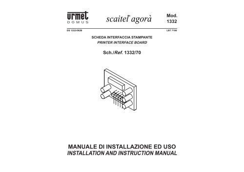
SCHEDA INTERFACCIA STAMPANTE<br />
PRINTER INTERFACE BOARD<br />
Sch./Ref. <strong>1332</strong>/<strong>70</strong><br />
MANUALE DI INSTALLAZIONE ED USO<br />
INSTALLATION AND INSTRUCTION MANUAL<br />
1
ITALIANO<br />
CONTENUTO DELLA CONFEZIONE<br />
• Scheda di <strong>interfaccia</strong> <strong>stampante</strong>.<br />
• Foglio di istruzioni.<br />
• Dischetto con il software di <strong>interfaccia</strong> per Windows<br />
95/98 versione Italiano e Inglese.<br />
• <strong>Ca</strong>vo di collegamento alla seriale terminato con<br />
un connettore PC 9 poli femmina.<br />
DESCRIZIONE<br />
Questo circuito si può inserire all’interno dei PABX<br />
Sch.<strong>1332</strong>/515, <strong>1332</strong>/528 e <strong>1332</strong>/512.<br />
La scheda di <strong>interfaccia</strong> <strong>stampante</strong> Sch.<strong>1332</strong>/<strong>70</strong> permette<br />
il collegamento del vostro centralino ad una <strong>stampante</strong> o<br />
ad una porta seriale del vostro PC per usufruire di una<br />
serie di prestazioni e servizi aggiuntivi sotto elencati.<br />
• Abilitazione/disabilitazione della stampa continua<br />
del traffi co telefonico e salvataggio nel buffer<br />
• Stampa della documentazione del traffi co telefonico<br />
entrante<br />
• <strong>Ca</strong>ncellazione del buffer traffi co entrante<br />
• Stampa della documentazione del traffi co telefonico<br />
uscente<br />
• <strong>Ca</strong>ncellazione del buffer traffi co uscente<br />
• Stampa della documentazione del traffi co telefonico<br />
entrante e uscente<br />
• <strong>Ca</strong>ncellazione dei buffer traffi co entrante uscente<br />
• Indicazione del contenuto buffer traffi co entrante/<br />
uscente<br />
• Segnalazione di buffer pieno oltre 80%<br />
• Stampa delle tabelle dei gestori, prefi ssi gestori e<br />
prefi ssi abilitati<br />
• Stampa dei dati di programmazione<br />
• Stampa dei numeri memorizzati in rubrica<br />
• INTERFACCIA PC<br />
• Lettura e scrittura delle programmazioni impostate<br />
• Monitor impegno derivati e linea urbana (campo<br />
lampade su PC)<br />
• Test rele’ attuatori<br />
INSTALLAZIONE E COLLEGAMENTI<br />
Per effettuare l’installazione dell’<strong>interfaccia</strong> bisogna operare<br />
nel seguente modo con il centralino non alimentato:<br />
• Estrarre le cappette di protezione che danno accesso<br />
alle morsettiere di collegamento; per far ciò occorre<br />
prima disimpegnarle dalla base svitando le viti con<br />
un cacciavite come indicato nel disegno:<br />
• Successivamente estrarre le cappette facendo<br />
forza con le dita nelle scanalature laterali<br />
• Estrarre il circuito indicato nel disegno (quello<br />
dei morsetti per il collegamento alla <strong>stampante</strong> o<br />
RS232 e campo lampade)<br />
• Togliere la cappa principale agendo con un cacciavite<br />
sulle due viti come indicato nel disegno<br />
• Inserire la scheda di <strong>interfaccia</strong> <strong>stampante</strong><br />
sch.<strong>1332</strong>/<strong>70</strong> facendo attenzione al verso di inserzione<br />
come indicato nel disegno nel connettore JP3<br />
• Richiudere la cappa principale con le due viti<br />
• Inserire il circuito come indicato in fi gura (quello<br />
dei morsetti per i collegamenti alla <strong>stampante</strong> o<br />
RS232 e campo lampade)<br />
• Effettuare i collegamenti richiesti dalla <strong>stampante</strong><br />
TX, RX, GND (per fare ciò seguire lo schema<br />
di collegamento presente nel manuale del vostro<br />
centralino) utilizzando il cavetto fornito a corredo<br />
dell’<strong>interfaccia</strong> stessa che termina con un connettore<br />
PC 9 poli femmina (vedi il dettaglio dei collegamenti<br />
qui sotto) oppure utilizzare un nuovo cavo<br />
rispettando le indicazioni dei collegamenti (eventualmente<br />
verifi care le connessioni nel manuale a<br />
corredo della vostra <strong>stampante</strong>)<br />
• Richiudere le due cappette<br />
2 DS<strong>1332</strong>-092B DS<strong>1332</strong>-092B<br />
3<br />
JP3<br />
JP2<br />
COLLEGAMENTO DEL CAVO SERIALE RS-232<br />
JP3<br />
Sch. <strong>1332</strong>/515 Sch. <strong>1332</strong>/528<br />
La lunghezza massima consentita per il collegamento seriale o <strong>stampante</strong> è di 10 mt.<br />
Morsetto del centralino <strong>Ca</strong>vo Connettore PC 9 poli Connettore PC 25 poli<br />
morsetto GND collegato con Nero pin 5 del connettore PC a 9 vie pin 7 del connettore PC 25 poli<br />
morsetto Tx collegato con Marrone pin 2 del connettore PC a 9 vie pin 3 del connettore PC 25 poli<br />
morsetto Rx collegato con Blu pin 3 del connettore PC a 9 vie pin 2 del connettore PC 25 poli<br />
I parametri di collegamento seriale sono i seguenti:<br />
velocità: 9600 baud stop: 1 bit di stop<br />
formato: 8 bit controllo fl usso: nessun controllo di fl usso<br />
parità: nessun bit di parità<br />
PRESTAZIONI E SERVIZI<br />
Sch. <strong>1332</strong>/512<br />
Per l’utilizzo delle prestazioni e i servizi aggiuntivi riferirsi al manuale a corredo del vostro centralino
INSTALLAZIONE DEL SOFTWARE DI<br />
INTERFACCIA IN AMBIENTE WINDOWS 95<br />
“SCAITERM” E CAMPO LAMPADE<br />
Prima di installare il programma “Scaiterm” vi consigliamo<br />
di aprire e leggere attentamente il fi le “Leggimi<br />
.txt”, in quanto vi sono contenute le informazioni<br />
utili all’installazione.<br />
Successivamente cliccare sull’icona “Setup.exe” e<br />
seguire le istruzioni in esso contenute per l’installazione<br />
completa.<br />
Per avviare il programma è necessario entrare nel<br />
menù avvio del vostro computer, sotto i “Programmi”<br />
e “Urmet Domus” (oppure nella cartella da voi scelta<br />
al posto di Urmet Domus) troverete le icone relative<br />
a “Sterm.exe”, “<strong>Ca</strong>mp.exe” e “Help”, cliccate su<br />
quella che vi interessa utilizzare e, se richiesta, inserite<br />
la password principale e premete invio.<br />
Automaticamente il programma selezionerà la porta<br />
seriale connessa al vostro centralino (che dovrà<br />
essere alimentato e connesso ad una porta seriale<br />
del vostro computer) e vi aprirà una fi nestra con delle<br />
icone che vi aiuteranno nelle varie programmazioni.<br />
All’interno del programma è predisposta una funzione<br />
di Help che vi aiuterà nell’utilizzo dello stesso.<br />
I requisiti minimi del vostro sistema dovranno essere<br />
i seguenti:<br />
• Processore: 486 o superiore<br />
• Clock 100 Mhz o superiore<br />
• Memoria Ram 16 MB<br />
• Spazio libero su HD 5MB<br />
NB Per l’utilizzo delle prestazioni sotto elencate<br />
occorre installare il software di <strong>interfaccia</strong> per<br />
Windows 95/98 “Scaiterm”.<br />
INTERFACCIA PC<br />
Tramite il collegamento alla porta seriale del vostro<br />
PC e il software di <strong>interfaccia</strong> “Scaiterm” è possibile<br />
accedere ad una serie di prestazioni con <strong>interfaccia</strong><br />
utente in ambiente windows ad esempio:<br />
• Programmazione di tutti i parametri del centralino<br />
• Controllo impegno linee e derivati<br />
• Verifi ca e stampa dei numeri telefonici in rubrica<br />
(rubrica estesa)<br />
• Abilitazioni delle funzioni sui derivati<br />
• Lettura e scrittura delle programmazioni impostate<br />
• Test relè attuatori<br />
Per tutte queste prestazioni è prevista una <strong>interfaccia</strong><br />
utente semplifi cata tramite icone grafi che.<br />
LETTURA E SCRITTURA DELLE PROGRAMMAZIONI<br />
IMPOSTATE<br />
Tramite il programma di <strong>interfaccia</strong> “Scaiterm” e il collegamento<br />
alla porta seriale del vostro PC è possibile<br />
effettuare la lettura o la scrittura di tutti i parametri di<br />
programmazione del vostro centralino e il loro salvataggio<br />
sotto forma di fi le. Questa operazione si può<br />
effettuare sia dal centralino verso il PC che viceversa.<br />
MONITOR IMPEGNO DERIVATI E LINEA URBANA<br />
(CAMPO LAMPADE SU PC)<br />
In alternativa al collegamento del circuito opzionale<br />
di campo lampade sch. <strong>1332</strong>/54 si può utilizzare il<br />
programma che permette, tramite la connessione<br />
della porta seriale del vostro PC al centralino la<br />
visualizzazione diretta del traffi co telefonico (dell’impegno<br />
della linea urbana, dei derivati e del citofono)<br />
sul vostro PC.<br />
Per attivare questa funzione sul vostro PC è<br />
suffi ciente cliccare sull’icona del programma<br />
“<strong>Ca</strong>mp.exe”<br />
TEST RELE’ ATTUATORI<br />
Tramite il programma di <strong>interfaccia</strong> “Scaiterm” e il<br />
collegamento seriale del vostro PC al centralino è<br />
possibile selezionare direttamente l’attuazione dei<br />
relè per verifi care il corretto funzionamento del vostro<br />
impianto.<br />
ENGLISH<br />
CONTENTS OF THE BOX<br />
• Printer interface board<br />
• Instruction sheet<br />
• Windows 95/98 interface software diskette (Italian<br />
and English version)<br />
• Serial cable with female 9-pin PC9 connector<br />
DESCRIPTION<br />
This circuit can be fi tted in PABX Ref.<strong>1332</strong>/515,<br />
<strong>1332</strong>/528 and <strong>1332</strong>/512.<br />
The printer interface board Ref. <strong>1332</strong>/<strong>70</strong> is used to<br />
connect your switchboard to a printer or to the serial<br />
port of your PC to exploit the following additional<br />
performances and services.<br />
• Enabling/disabling telephone traffi c form print and<br />
storing in buffer<br />
• Printing incoming telephone traffi c information<br />
• Deleting incoming traffi c buffer<br />
• Printing outgoing telephone traffi c information<br />
• Deleting outgoing traffi c buffer<br />
• Printing incoming and outgoing telephone traffi c<br />
information<br />
• Deleting incoming and outgoing traffi c buffer<br />
• Indicating contents of incoming and outgoing traffi c<br />
buffer<br />
• Signally buffer full over 80%<br />
• Printing telephone carrer, telephone carrer codes<br />
and enabled telephone code tables<br />
• Printing programming data<br />
• Printing stored directory telephone numbers<br />
• PC INTERFACE<br />
• Reading and writing programming settings<br />
• Monitoring station and local line use (LED block on PC)<br />
• Actuator relay test<br />
INSTALLATION AND CONNECTIONS<br />
Proceed as follows to install the interface with the<br />
switchboard not powered:<br />
• Remove the covers over the connection terminal<br />
boards. To do so, you will fi rstly need to release<br />
them from the base by loosening the screws shown<br />
in the drawing with a screwdriver.<br />
• Then remove the covers forcing the side grooves<br />
with your fi ngers.<br />
• Remove the circuit shown in the drawing (the one<br />
of the terminals for connecting to the printer or<br />
RS232 and to the LED block).<br />
• Remove the main cover by loosening the two<br />
screws shown in the drawing with a screwdriver.<br />
• Fit the printer interface board ref. <strong>1332</strong>/<strong>70</strong> being<br />
careful to respect the direction of connector JP3<br />
shown in the drawing.<br />
• Close the main cover with two screws.<br />
• Fit the circuit as shown in the fi gure (the one of the<br />
terminals for connecting to the printer or RS232<br />
and to the LED block).<br />
• Make the TX, RX, GND connections to the printer<br />
as required (refer to the connection diagram in your<br />
switchboard manual). Use the cable with a female<br />
9-pin PC9 connector provided with the interface<br />
(see connection details below). Alternatively, use<br />
a new cable respecting the connection indications<br />
given (if required, check the connections in the<br />
manual provided with your printer).<br />
• Close the two covers.<br />
4 DS<strong>1332</strong>-092B DS<strong>1332</strong>-092B<br />
5
JP3<br />
JP2<br />
JP3<br />
Ref. <strong>1332</strong>/515 Ref. <strong>1332</strong>/528<br />
SERIAL WIRE RS-232 CONNECTION<br />
The maximum permissible length for the serial connection (or connection to the printer) is 10 metres.<br />
Switchboard terminal Wire 9-pin PC connector 25-pin PC connector<br />
GND terminal connected to Black pin 5 (9-pin PC connector) pin 7 (25-pin PC connector)<br />
Tx terminal connected Brown pin 2 (9-pin PC connector) pin 3 (25-pin PC connector)<br />
Rx terminal connected to Blue pin 3 (9-pin PC connector) pin 2 (25-pin PC connector)<br />
The serial connection parameters are:<br />
Baud rate: 9600 baud Stop: 1 stop bit<br />
Format: 8 bit Flow control: no fl ow control<br />
Parity: no parity bit<br />
PERFORMANCE AND SERVICES<br />
Ref. <strong>1332</strong>/512<br />
Refer to the manual provided with your switchboard for instructions on how to use the additional performances<br />
and services.<br />
“SCAITERM” WINDOWS 95/98 INTERFACE<br />
AND LED BLOCK SOFTWARE SETUP<br />
In order to install the program click on “Setup.exe”<br />
icon and follow the prompts for complete installation.<br />
Open the start menu on your computer to start the<br />
program. In Programs, Urmet Domus (or the folder<br />
you chose instead of Urmet Domus) you will fi nd the<br />
“Sterm.exe”, “<strong>Ca</strong>mp.exe” and “Help” icons. Click<br />
on the icon you want. If required, enter your main<br />
password and press Enter.<br />
The program will automatically select the serial<br />
port connected to your switchboard (which must<br />
be powered and connected to a serial port of your<br />
computer) and will open a window containing icons<br />
to help you in the programming procedure.<br />
The Help function will help you use the program.<br />
The minimum system requirements are:<br />
• Processor: 486 or higher<br />
• Clock 100 MHz or higher<br />
• RAM 16 MB<br />
• Free space on HD 5MB<br />
N.B.: You must install the Scaiterm Windows 95/98<br />
interface software to use the performance<br />
listed below.<br />
PC INTERFACE<br />
A set of functions (Windows user interface) can be<br />
accessed by connecting to the serial port of your<br />
PC and using the “Scaiterm” interface software.<br />
Functions include:<br />
• Programming all switchboard parameters<br />
• Monitoring line and station use<br />
• Check and printing telephone directory numbers<br />
(extended directory)<br />
• Enabling station functions<br />
• Reading and writing program settings<br />
• Actuator relay test<br />
A simplifi ed user interface with graphic icons is<br />
provided for each of these functions.<br />
READING AND WRITING PROGRAM SETTINGS<br />
You can read and write all your switchboard<br />
programming parameters and save them to fi les<br />
by means of the “Scaiterm” interface software and<br />
connection to the serial port of your PC. This operation<br />
can be carried out both from the switchboard to the<br />
PC and vice versa.<br />
MONITORING STATION AND LOCAL LINE USE<br />
(LED BLOCK ON PC)<br />
As an alternative to the optional LED block circuit<br />
Ref. <strong>1332</strong>/54, you can use the program which directly<br />
displays the telephone traffi c (local line use, station<br />
use, door phone use) on your PC via a serial port<br />
connection.<br />
Simply click on the “<strong>Ca</strong>mp.exe” program icon on<br />
your PC to start this function.<br />
ACTUATOR RELAY TEST<br />
You can directly actuate the relays and check the<br />
correct operation of your system by means of the<br />
“Scaiterm” interface program and a serial connection<br />
to your PC.<br />
6 DS<strong>1332</strong>-092B DS<strong>1332</strong>-092B<br />
7
La URMET DOMUS si riserva il diritto di apportare modifi che alle proprie apparecchiature, in qualsiasi<br />
momento, senza darne preavviso.<br />
URMET DOMUS reserves the right to change the devices in any moment without prior notice.<br />
DS <strong>1332</strong>-092B LBT 7190<br />
FILIALI STABILIMENTO<br />
20151 MILANO - Via Gallarate 218<br />
Tel. 02.380.111.75 - Fax 02.380.111.80<br />
00043 CIAMPINO (ROMA) - Via L.Einaudi 17/19A<br />
Tel. 06.791.07.30 - Fax 06.791.48.97<br />
8<br />
http://www.<strong>urmet</strong>domus.it<br />
e-mail:info@<strong>urmet</strong>domus.it<br />
URMET DOMUS S.p.A.<br />
10154 TORINO (ITALY)<br />
VIA BOLOGNA 188/C<br />
Telef. 011.24.00.000 (RIC. AUT.)<br />
Fax 011.24.00.300<br />
011.24.00.323<br />
DS<strong>1332</strong>-092B