
You also want an ePaper? Increase the reach of your titles
YUMPU automatically turns print PDFs into web optimized ePapers that Google loves.
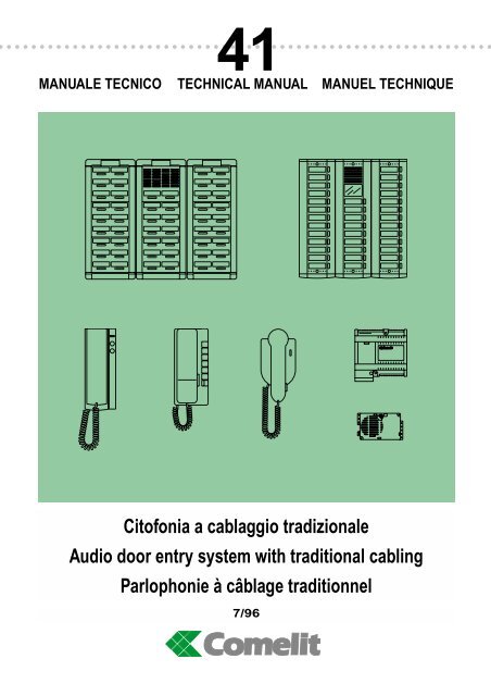
MANUALE TECNICO 41<br />
TECHNICAL MANUAL MANUEL TECHNIQUE<br />
Citofonia a cablaggio tradizionale<br />
Audio door entry system with traditional cabling<br />
Parlophonie à câblage traditionnel<br />
7/96
SOMMARIO<br />
• GENERALITA'<br />
E PRESTAZIONI pag. 2<br />
•<br />
POSTAZIONI ESTERNE<br />
Pulsantiera modulare<br />
Logicom<br />
Pulsantiera semimodulare<br />
pag. 3<br />
Unicom pag. 8<br />
•<br />
•<br />
POSTAZIONI INTERNE<br />
E ACCESSORI pag. 14<br />
NORME GENERALI PER<br />
L'INSTALLAZIONE pag. 21<br />
• COLLAUDO<br />
IMPIANTO pag. 23<br />
•<br />
RICERCA GUASTI pag. 24<br />
• VARIANTI<br />
AGLI SCHEMI pag. 26<br />
• DESCRIZIONE<br />
IMPIANTI pag. 32<br />
C5/01 Impianto di portiere<br />
citofonico di base pag. 32<br />
C5/02 Impianto di portiere<br />
con 2 posti esterni pag. 34<br />
C5/03 Impianto di portiere<br />
con 3 posti esterni pag. 36<br />
C5/10 Impianto di portiere<br />
con 1 posto esterno principale<br />
e tanti secondari pag. 38<br />
C5/13 Impianto intercomunicante<br />
con 9 citofoni Okay pag. 40<br />
C5/13A Impianto intercomunicante<br />
con 8 citofoni Vox pag. 40<br />
C5/14 Impianto di portiere con 4<br />
citofoni intercomunicanti Okay o<br />
Vox pag. 42<br />
C5/15 Impianto di portiere con<br />
2 posti esterni e citofoni<br />
intercomunicanti<br />
Okay o Vox pag. 44<br />
C5/16 Impianto di portiere con<br />
gruppi di citofoni normali<br />
o intercomunicanti pag. 46<br />
C5/17 Impianto di portiere<br />
con 2 posti esterni ed<br />
elettroserrature abbinate pag. 48<br />
SUMMARY<br />
•<br />
•<br />
GENERAL INFORMATION AND<br />
PERFORMANCES pag. 2<br />
EXTERNAL UNITS<br />
Logicom modular<br />
entrance panel<br />
Unicom semi-modular<br />
pag. 3<br />
entrance panel pag. 8<br />
•<br />
•<br />
INTERNAL UNITS AND<br />
ACCESSORIES pag. 14<br />
GENERAL INDICATION FOR<br />
INSTALLATION pag. 21<br />
• TESTING<br />
THE SYSTEM pag. 23<br />
•<br />
•<br />
•<br />
TROUBLE SHOOTING pag. 24<br />
VARIATIONS OF<br />
DIAGRAMS pag. 26<br />
DESCRIPTION OF<br />
SYSTEMS pag. 32<br />
C5/01 Basic door entry<br />
system pag. 32<br />
C5/02 Door entry system<br />
with 2 external units pag. 34<br />
C5/03 Door entry system<br />
with 3 external units pag. 36<br />
C5/10 Door entry system with<br />
one main external unit and<br />
several secondary units pag. 38<br />
C5/13 Intercom phone<br />
system with 9 Okay<br />
telephones pag. 40<br />
C5/13A Intercom phone<br />
system with 8 Vox<br />
telephones pag. 40<br />
C5/14 Door entry system<br />
with 4 Okay or Vox<br />
telephones pag. 42<br />
C5/15 Door entry system<br />
with 2 external units<br />
and Okay or Vox intercom<br />
phones pag. 44<br />
C5/16 Door entry system<br />
with groups of normal or<br />
intercom telephones pag. 46<br />
C5/17 Door entry system<br />
with 2 entrance panels and<br />
combined electric locks pag. 48<br />
SOMMAIRE<br />
• GENERALITES<br />
ET SERVICES pag. 2<br />
• POSTES EXTERIEURS<br />
Plaque de rue<br />
modulaire Logicom<br />
Plaque de rue semi-<br />
pag. 3<br />
modulaire Unicom pag. 8<br />
•<br />
•<br />
•<br />
•<br />
•<br />
•<br />
<strong>MT</strong>/41<br />
POSTES INTERIEURS<br />
ET ACCESSOIRES pag. 14<br />
NORMES GENERALES<br />
POUR L'INSTALLATION pag. 21<br />
TEST DE<br />
L'INSTALLATION pag. 23<br />
RECHERCHE PANNES pag. 24<br />
VARIANTE SUR<br />
LES SCHEMAS pag. 26<br />
DESCRIPTION DES<br />
INSTALLATIONS pag. 32<br />
C5/01 Installation<br />
parlophonique de base pag. 32<br />
C5/02 Installation parlophonique<br />
avec 2 postes exterieurs pag. 34<br />
C5/03 Installation parlophonique<br />
avec 3 postes extérieurs pag. 36<br />
C5/10 Installation parlophonique<br />
avec 1 poste extérieur<br />
principal et plusieurs postes<br />
secondaires pag. 38<br />
C5/13 Installations<br />
intercommunicante avec<br />
9 combinés Okay pag. 40<br />
C5/13A Installations<br />
intercommunicante avec<br />
8 combinés Vox pag. 40<br />
C5/14 Installation parlophonique<br />
avec 4 combinés intercommunicants<br />
Okay ou Vox pag. 42<br />
C5/15 Installation parlophonique<br />
avec 2 postes extérieurs et<br />
combinés Okay ou Vox<br />
intercommunicants pag. 44<br />
C5/16 Installation parlophonique<br />
avec groupes de combinés<br />
normaux ou<br />
intercommunicants pag. 46<br />
C5/17 Installation parlophonique<br />
avec 2 postes exterieurs et<br />
gâches accuoplées pag. 48<br />
1
GENERALITA'<br />
E PRESTAZIONI<br />
Il sistema citofonico descritto in<br />
questo manuale tecnico è stato progettato<br />
per soddisfare le più svariate<br />
esigenze della clientela.<br />
Il posto esterno<br />
La pulsantiera esterna può essere<br />
composta utilizzando apparecchiature<br />
di diverse serie più avanti<br />
descritte:<br />
• modulare Logicom ove possono<br />
essere ospitati moduli e accessori<br />
per svariate funzioni;<br />
• monoplacca Unicom di dimensioni<br />
ridotte e dal prezzo contenuto;<br />
• monoplacca in ottone o antivandalo<br />
in acciaio, ampiamente descritta<br />
sul catalogo generale.<br />
I posti interni<br />
I citofoni possono essere scelti fra:<br />
• la serie Okay componibile di altissima<br />
qualità;<br />
• la serie Vox componibile di qualità<br />
professionale;<br />
• la serie Ciao di dimensioni ridotte<br />
e del prezzo contenuto.<br />
Gli alimentatori e gli accessori sono<br />
tutti del tipo modulare da fissare su<br />
barra DIN oppure a parete.<br />
Gli impianti<br />
Gli impianti realizzabili sono:<br />
• impianti citofonici con uno o più<br />
posti esterni e un numero illimitato<br />
di citofoni;<br />
• intercomunicanti;<br />
• intercomunicanti con uno o più<br />
posti esterni;<br />
• con centralino di portineria<br />
(descritti su un apposito manuale<br />
tecnico);<br />
• speciali con precise richieste del<br />
cliente.<br />
Per impianti mono o bifamiliari si<br />
consigliano i kit citofonici Comelkit<br />
descritti sul catalogo generale.<br />
La COMELIT Group esegue qualsiasi<br />
tipo di impianto citofonico speciale<br />
su richiesta del cliente. In questo<br />
caso è indispensabile che il<br />
cliente fornisca tutte le informazioni<br />
possibili in particolar modo le funzioni<br />
dell'impianto e le distanze.<br />
2<br />
GENERAL INFORMATION<br />
AND PERFORMANCES<br />
The door entry system described in<br />
this technical manual is designed to<br />
meet widely differing requirements.<br />
The external unit<br />
The entrance panel can be composed<br />
by using equipment from various<br />
series described further on :<br />
• Logicom modular panel, which<br />
can house modules and<br />
accessories for various functions;<br />
• Unicom single-plate with small<br />
dimensions and low price;<br />
• Single-plate made of brass or<br />
stainless steel vandalproof, widely<br />
described in our general catalogue.<br />
Internal units<br />
The telephones can be choosen<br />
among the following:<br />
• Okay series, high quality and<br />
preset for various accessories;<br />
• Vox series, professional quality<br />
and preset for various accessories;<br />
• Ciao series, small dimensions<br />
and low price.<br />
The power supplies and accessories<br />
are all modular and can be<br />
fixed to a DIN bar or surface mounted.<br />
Systems<br />
The possible systems are the<br />
following:<br />
• door entry sistems with one or<br />
more entrances;<br />
• Intercom systems;<br />
• Intercom systems with one or<br />
more entrances;<br />
• with central porter switchboard<br />
(described on a technical manual);<br />
• special systems on customer’s<br />
request.<br />
For single or two-family systems we<br />
recommend the Comelkit door entry<br />
kits described in our general<br />
catalogue.<br />
COMELIT Group constructs any<br />
type of special door entry system on<br />
the customer's request. In this case,<br />
it is essential for the customer to<br />
provide all possible information with<br />
particular regard to the functions of<br />
the system and distances covered.<br />
GENERALITES<br />
ET SERVICES<br />
Le système parlophonique décrit<br />
dans ce manuel technique a été<br />
projété pour satisfaire les exigences<br />
les plus différentes de la clientèle.<br />
Le poste extérieur<br />
La plaque de rue peut être composée<br />
en employant des appareils<br />
de séries différentes décrites cidessous:<br />
• séries Logicom, qui comprend des<br />
modules et accessoires pour différentes<br />
fonctionc;<br />
• monoplaque Unicom avec dimensions<br />
réduites et prix contenus;<br />
• monoplaque en laiton ou antivandale<br />
en acier inox et aluminium<br />
décrite dans le catalogue général.<br />
Les postes intérieurs<br />
Les combinés peuvent être choisis<br />
parmi:<br />
• la séries Okay, à éléments, de très<br />
haute qualité;<br />
• la séries Vox, à éléments, de qualité<br />
professionnelle;<br />
• la séries Ciao, avec dimensions<br />
réduites et prix contenu.<br />
Les alimentations et les accessoires<br />
sont tous du type modulaire à fixer<br />
sur rail DIN ou en saillie.<br />
Les installations<br />
On peut réaliser les installations<br />
suivantes:<br />
• installations parlophoniques avec<br />
un ou plusieurs postes extérieurs et<br />
un nombre illimité de combinés;<br />
• installations intercommunicantes;<br />
• installations intercommunicantes<br />
avec un ou plusieurs postes<br />
extérieurs;<br />
• installations avec standard de<br />
conciergerie (décrites dans un<br />
manuel technique approprié);<br />
• installations parlophoniques spéciales<br />
sur demande précise du<br />
client.<br />
Pour installations pour un ou deux<br />
usagers on conseille les kits parlophoniques<br />
Comelkit décrits dans le<br />
catalogue général.<br />
COMELIT Group<br />
exécute n’importe quel type d’installation<br />
spéciale de portier sur<br />
demande du client. Dans ce cas il<br />
est indispensable que le client fournisse<br />
toutes les informations possibles<br />
et de manière particulière les<br />
fonctions de l’installation et les distances.
POSTAZIONI ESTERNE<br />
Descrizione e caratteristiche<br />
tecniche della pulsantiera<br />
modulare Logicom<br />
Il sistema modulare Logicom si<br />
caratterizza per la semplicità di<br />
inserimento dei moduli nelle guide<br />
dei telai, la ricca gamma dei moduli,<br />
degli accessori e per la versione da<br />
incasso e da esterno.<br />
Il frontale dei moduli è in alluminio<br />
estruso da 1,5 mm di spessore anodizzato<br />
o verniciato; il pulsante è in<br />
alluminio imbutito. Il contatto del<br />
pulsante è realizzato con un microswitch.<br />
I moduli che compongono il posto<br />
esterno sono disponibili in tre colori:<br />
• alluminio anodizzato;<br />
• bianco;<br />
• grigio metalizzato Comelit.<br />
Per la composizione del posto<br />
esterno, l’assemblaggio e l’installazione,<br />
vedi alle pag. 6-7.<br />
Scatole da incasso<br />
per 1-2-3 moduli.<br />
Dimensioni:<br />
127 x 127 x 45 mm<br />
127 x 217 x 45 mm<br />
127 x 305 x 45 mm.<br />
Telai portamoduli<br />
per 1-2-3 moduli.<br />
Dimensioni:<br />
125 x 125 x 15 mm<br />
125 x 215 x 15 mm<br />
125 x 305 x 15 mm.<br />
Visiere antipioggia<br />
Utili per proteggere il posto esterno<br />
da incasso dalla pioggia. Si inseriscono<br />
fra la scatola e la pulsantiera<br />
(vedi a pag. 7). Sono utilizzabili<br />
rispettivamente per le pulsantiere<br />
da 1-2-3-4-6-9 moduli.<br />
artt. 3110/1-2-3<br />
artt. 3111/1-2-3<br />
artt. 3112/1-2-3-4-6-9<br />
EXTERNAL UNITS<br />
Description and technical characteristics<br />
of the Logicom modular<br />
entrance panel<br />
The Logicom modular system provides<br />
a wide range of modules and<br />
accessories available in both flush<br />
and surface mounted versions,<br />
ansuring the ease of installation of<br />
the modules into the frame guides.<br />
Front plates are made of 1.5 mm<br />
thick, anodized or varnished drawn<br />
aluminium. The push button is<br />
made of drawn aluminium and his<br />
contact consist of a microswitch.<br />
The modules which make up the<br />
external unit are available in three<br />
colours:<br />
• anodized aluminium<br />
• white<br />
• Comelit metallic grey.<br />
See examples of entrance panel<br />
composition, assembly and<br />
installation on pages 6-7.<br />
Flush mounted boxes<br />
for 1-2-3 modules.<br />
Dimensions:<br />
127 x 127 x 45 mm<br />
127 x 217 x 45 mm<br />
127 x 305 x 45 mm.<br />
Module-holder frames<br />
from 1-2-3 modules.<br />
Dimensions:<br />
125 x 125 x 15 mm<br />
125 x 215 x 15 mm<br />
125 x 305 x 15 mm.<br />
Rain shields<br />
They are used to protect the flushmounted<br />
external unit from the rain.<br />
To be inserted between the box and<br />
the push-button panel (see on page<br />
7). They can be used for the 1-2-3-<br />
4-6-9 module push-button panels<br />
respectively.<br />
<strong>MT</strong>/41<br />
POSTES EXTERIEURS<br />
Description et caractéristiques<br />
techniques de la plaque de rue<br />
modulaire Logicom<br />
Le système modulaire Logicom a<br />
comme caractéristique la facilité<br />
d’insertion des modules dans les<br />
guides des cadres, une gamme<br />
riche en modules et accessoires,<br />
soit pour la version à encaster que<br />
pour celle en saillie.<br />
La face avant des modules est en<br />
aluminium extrudé de 1,5 mm<br />
d’épaisseur, anodisé ou verni; le<br />
bouton poussoir est en aluminium<br />
embouti. Le contact du bouton<br />
poussoir est réalisé par un microinterrupteur<br />
Les modules qui composent le<br />
poste extérieur sont disponible en<br />
trois couleurs:<br />
• aluminium<br />
• blanc<br />
• gris metallisé Comelit.<br />
Pour la composition du poste<br />
extérieur, l’assemblage et l’installation,<br />
voir pages 6-7.<br />
Boîtes à encastrer<br />
pour 1-2-3 modules.<br />
Dimensions:<br />
127 x 127 x 45 mm<br />
127 x 217 x 45 mm<br />
127 x 305 x 45 mm.<br />
Cadres porte-modules<br />
pour 1-2-3 modules.<br />
Dimensions:<br />
125 x 125 x 15 mm<br />
125 x 215 x 15 mm<br />
125 x 305 x 15 mm.<br />
Protections anti-pluie<br />
Très utiles pour protéger de la pluie<br />
un poste extérieur encastré. Elles<br />
se placent entre la boîte et la<br />
plaque de rue (voir page 7).<br />
Adaptées respectivement aux<br />
plaques de rue à 1-2-3-24-6-9 modules.<br />
3
Cornici<br />
Utili per eliminare le imperfezioni<br />
della parete intorno al perimetro<br />
della scatola incassata. Si inseriscono<br />
fra la scatola e la pulsantiera<br />
(vedi fig. a pag. 7).<br />
Sono utilizzabili rispettivamente per<br />
le pulsantiere da 1-2-3-4-6-9 moduli.<br />
Custodie<br />
Utili quando si sceglie la soluzione<br />
da parete e per ottenere una protezione<br />
totale dalla pioggia. Si fissa<br />
direttamente alla parete (vedi fig. a<br />
pag. 7). Sono utilizzabili rispettivamente<br />
per le pulsantiere da 1-2-3-4-<br />
6-9 moduli. Devono essere equipaggiate<br />
dei relativi telai portamoduli.<br />
Modulo senza pulsanti<br />
Predisposto per il solo alloggiamento<br />
del portiere audio.<br />
Dimensioni: 108x90x30 mm.<br />
Moduli con 1 e 2 pulsanti<br />
Predisposti per l'alloggiamento del<br />
portiere audio, completi di lampada<br />
illuminazione portanomi da 3W 15V<br />
a siluro.<br />
Dimensioni: 108x90x30 mm.<br />
Moduli con 4 e 6 pulsanti<br />
Completi di lampada illuminazione<br />
portanomi da 3W 15V a siluro.<br />
Dimensioni: 108x90x30 mm.<br />
Modulo cieco<br />
Per occupare moduli vuoti con il<br />
minor costo possibile.<br />
Dimensioni: 108x90x30 mm.<br />
Modulo PTT<br />
Predisposto per l'alloggiamento<br />
della chiave PTT.<br />
Dimensioni: 108x90x30 mm.<br />
Modulo illuminato<br />
Per segnalazioni diverse come<br />
numero civico, segnali di occupato<br />
ecc. Completo di lampada da 3W<br />
15V a siluro. Spazio utile per la<br />
scritta 88x78 mm.<br />
Dimensioni: 108x90x30 mm.<br />
4<br />
artt. 3114/1-2-3-4-6-9<br />
artt. 3116/1-2-3-4-6-9<br />
art. 3120/0<br />
artt. 3120/1 - 3120/2<br />
art. 3122/4 - 3122/6<br />
art. 3124<br />
art. 3125<br />
art. 3126<br />
Frames<br />
They are use to eliminate any<br />
imperfections in the wall surrounding<br />
the flush-mounted box. To be<br />
inserted between the box and the<br />
push-button panel (see on page 7).<br />
They can be used for the 1-2-3-4-6-<br />
9 module push-button panels<br />
respectively.<br />
Housing<br />
They are used when the surfacemounted<br />
solution is chosen and to<br />
obtain total protection from the rain.<br />
To be fixed directly to the wall (see<br />
on page 7). They can be used for<br />
the 1-2-3-4-6-9 module push-button<br />
panels respectively. Must be<br />
equipped with relative module-holder<br />
frames.<br />
Module without push-buttons<br />
Preset to house the speaker unit<br />
only.<br />
Dimensions: 108x90x30 mm.<br />
Modules with 1 and 2 push-buttons<br />
Preset to house the speaker unit,<br />
complete with 3W 15V festoon lamp<br />
for nameplate illumination.<br />
Dimensions: 108x90x30 mm.<br />
Modules with 4 and 6 push-buttons<br />
Complete with 3W 15V festoon<br />
lamp for nameplates illumination.<br />
Dimensions: 108x90x30 mm.<br />
Blank module<br />
To occupy empty modules at the<br />
lowest possible cost.<br />
Dimensions: 108x90x30 mm.<br />
PPT module<br />
Preset for housing the PPT key.<br />
Dimensions: 108x90x30 mm.<br />
Illuminated module<br />
For different signals, such as road<br />
number, busy signal, etc. Complete<br />
with 3W 15V festoon lamp. Free<br />
space for writing 88x78 mm.<br />
Dimensions: 108x90x30 mm.<br />
Cadres<br />
Utiles pour éliminer les imperfections<br />
du mur autour du périmètre de<br />
la boîte encastrable. Ils s’insèrent<br />
entre la boîte et la plaque de rue<br />
(voir fig. pag. 7).<br />
On les utilise respectivement pour<br />
les plaques de rue de 1-2-3-4-6-9<br />
modules.<br />
Boîtiers anti-pluie<br />
Utiles lorqu’on choisit la solution en<br />
saillie. Ills se fixent au mur (voir fig.<br />
pag. 7). On utilise respectivement<br />
pour les plaques de rue de 1-2-3-4-<br />
6-9 modules. Ils sont fournis avec<br />
les châssis respectivement pour 1-<br />
2-3-4-6-9 modules.<br />
Module sans boutons<br />
Conçu uniquement pour le logement<br />
du HP-Micro. Dimensions:<br />
108x90x30 mm.<br />
Modules avec 1 ou 2 boutons<br />
Conçus pour le logement du HP-<br />
Micro, avec illumination des porteétiquettes<br />
par lampes “navette” de<br />
3W 15V. Dimensions: 108x90x30<br />
mm.<br />
Modules avec 4 ou 6 boutons<br />
Avec illumination des porte-étiquettes<br />
par lampes “navette” de 3W<br />
15V.<br />
Dimensions: 108x90x30 mm.<br />
Module obturateur (accessoire)<br />
Pour occuper les modules vides<br />
avec un coût le plus bas possible.<br />
Dimensions: 108x90x30 mm.<br />
Module PTT<br />
Conçu pour le logement de la clé<br />
PTT. Dimensions: 108x90x30 mm.<br />
Module illuminé<br />
Pour les signalisations diverses<br />
comme le numéro de rue, signal<br />
occupé etc. Avec lampe “navette”<br />
de 3W 15V. Espace utile pour<br />
l’inscription 88x78 mm. Dimensions:<br />
108x90x30 mm.
Modulo Logicode<br />
Componendo un codice da 1 a 8<br />
cifre mediante una tastiera digitale è<br />
possibile attivare un relè che consente<br />
di comandare qualsiasi dispositivo<br />
comandabile con un contatto<br />
NO. Ad esempio serrature elettriche,<br />
cancelli automatici, antifurti ecc. Il<br />
codice è programmabile attraverso<br />
la tastiera e può essere facilmente<br />
cambiato. Il dispositivo inoltre è corredato<br />
di un buzzer e di due led per<br />
indicare la corretta esecuzione delle<br />
manovre. Le caratteristiche tecniche<br />
e lo schema di collegamento sono a<br />
corredo dell'apparecchiatura.<br />
Dimensioni: 108x90x30 mm.<br />
Modulo Logicode<br />
Come art. 3127/I sopra descritto ma<br />
con la differenza che dispone di 2<br />
relé che possono azionare 2 dispositivi<br />
diversi.<br />
Dimensioni: 108x90x30 mm.<br />
Portiere audio per pulsantiere<br />
Logicom e Unicom<br />
Con doppio amplificatore, altoparlante<br />
stagno e microfono electret. E'<br />
dotato di regolatore per il volume<br />
esterno contraddistinto dal simbolo<br />
dell'altoparlante e dal regolatore per<br />
il volume interno senza simbolo. Da<br />
inserire nei moduli artt. 3120/0-1-2.<br />
Dimensioni: 95x55x33 mm.<br />
Descrizione morsettiera:<br />
2 uscita per l'altoparlante del<br />
citofono<br />
3 entrata microfono del citofono<br />
4 - + alimentazione 10V DC<br />
C segnalatore acustico di<br />
chiamata.<br />
Pulsantiera Logipost<br />
Art. 3634 Pulsantiera con cassetta<br />
lettere, realizzata in alluminio anodizzato<br />
al naturale. Può essere<br />
installata a parete o su recinzione.<br />
Apertura anteriore. Predisposta per<br />
l'alloggiamento di 2 moduli<br />
Logicom. Dimensioni: 260x490x90.<br />
Art. 3637 Protezione antipioggia<br />
per art. 3634.<br />
Art. 3635 Come art. 3634 ma con<br />
apertura posteriore.<br />
Art. 3638 Protezione antipioggia<br />
per art. 3635.<br />
Art. 3636 Come art. 3634 ma predisposta<br />
per 3 moduli Logicom.<br />
Dimensioni: 385x412x150 mm.<br />
art. 3127/I<br />
art. 3128/I<br />
art. 1100/U<br />
Logipost<br />
Logicode module<br />
By entering a 1 to 8 figure code on<br />
the digital push-button panel a relay<br />
can be activated making it possible<br />
to operate any device controllable<br />
with a NO contact. For example,<br />
electric locks, automatic gates, antitheft<br />
devices etc. The code can be<br />
programmed by means of the pushbutton<br />
panel and is easily changed.<br />
The device is also fitted with 1<br />
buzzer and 2 LEDs to indicate correct<br />
functioning of the operations.<br />
Technical characteristics and the<br />
connecting diagram are supplied<br />
with the equipment.<br />
Dimensions: 108x90x30 mm.<br />
Logicode module<br />
As per art. 3127/I described above,<br />
but differing in the fact that it has 2<br />
relays which can activate 2 different<br />
divices.<br />
Dimensions: 108x90x30 mm.<br />
Speaker unit for Logicom and<br />
Unicom entrance panels<br />
With double amplifier. Weatherproof<br />
loudspeaker and electret microphone.<br />
It is fitted with an external<br />
volume adjustment marked with<br />
loud-speaker symbol and it is fitted<br />
with an internal volume adjustment<br />
without a symbol. To be inserted in<br />
Logicom modules art. 3120/0-1-2.<br />
Dimensions: 95x55x27 mm.<br />
Terminal board description:<br />
2 output for phone loudspeaker<br />
3 phone microphone input<br />
4 - + 10V DC power supply<br />
C acoustic call signal<br />
Logipost entrance panel<br />
Art. 3634 Entrance panel with letter<br />
box in natural anodized aluminium.<br />
Can be fitted to wall or fence. Front<br />
opening. Designed to house 2<br />
Logicom modules.<br />
Dimensions: 260x490x90 mm.<br />
Art. 3637 Rain shield per art. 3634.<br />
Art. 3635 As per art. 3634 but with<br />
rear opening.<br />
Art. 3638 Rain shield per art. 3635<br />
Art. 3636 As per art. 3634 but<br />
designed to house 3 Logicom modules.<br />
Dimensions: 385x412x150 mm.<br />
<strong>MT</strong>/41<br />
Module Logicode<br />
En composant un code de 1 à 8<br />
chiffres sur un clavier digital on<br />
active un relais qui permet de commander<br />
tout dispositif commandable<br />
par un contact NO. Par exemple<br />
serrures électriques, portails<br />
automatiques, anti-vols etc. Le code<br />
est programmable à l’aide du clavier<br />
et peut être facilement changé. Le<br />
dispositif est en outre doté de LEDs<br />
et de buzzer pour indiquer la bonne<br />
exécution des manoeuvres. Les<br />
caractéristiques techniques et le<br />
schéma de branchement sont fournis<br />
avec l’appareil.<br />
Dimensions: 108x90x30 mm.<br />
Module Logicode<br />
Comme art. 3127/I décrit ci-dessus<br />
mais avec la différence qu’il dispose<br />
de 2 codes qui peuvent actionner 2<br />
dispositif différents. Dimensions:<br />
108x90x30 mm.<br />
HP/Micro pour plaques de rue<br />
Logicom et Unicom<br />
Avec double amplificateur, haut-parleur<br />
étanche et microphone “électret”.<br />
Il est doté d’un réglage pour le<br />
volume externe marqué par le symbole<br />
du haut-parleur et du réglage<br />
pour le volume interne sans symbole.<br />
A insérer dans les modules<br />
art. 3120/2-1-2.<br />
Dimensions: 95x55x27 mm.<br />
Description du bornier:<br />
2 sortie pour le haut-parleur<br />
3 entrée du microphone du<br />
combiné<br />
4 - + alimentation 10V DC<br />
C signal acoustique d’appel<br />
Plaque de rue Logipost<br />
Art. 3634 Plaque de rue avec boîte<br />
aux lettres, en aluminium anodisé<br />
naturel. Installation en saillie ou sur<br />
clôture. S’ouvre par-l’avant. Prévue<br />
pour 2 modules Logicom.<br />
Dimensions: 260x490x90 mm.<br />
Art. 3637 Protection anti-pluie pour<br />
art. 3634.<br />
Art. 3635 Comme art. 3634 mais<br />
avec ouverture par l’arrière.<br />
Art. 3638 Protection anti-pluie pour<br />
art. 3635.<br />
Art. 3636 Comme art. 3634 mais<br />
prévue pour 3 modules Logicom.<br />
Dimensions: 385x412x150 mm.<br />
5
Esempi di composizione<br />
pulsantiera Logicom<br />
6<br />
N° Pulsanti<br />
NO. of Push-Button<br />
N° Bouton-Poussoirs<br />
1<br />
2<br />
3<br />
4<br />
5<br />
6<br />
7<br />
8<br />
9<br />
10<br />
12<br />
14<br />
16<br />
18<br />
20<br />
22<br />
24<br />
26<br />
28<br />
30<br />
32<br />
34<br />
36<br />
38<br />
40<br />
42<br />
44<br />
46<br />
48<br />
50<br />
Logicom<br />
125 x 125 mm<br />
125 x 215 mm<br />
125 x 305 mm<br />
252 x 215 mm<br />
252 x 305 mm<br />
379 x 305 mm<br />
• Completare la pulsantiera con portiere Art. 1100/U<br />
• Complete the entrance panel with speaker unit Art. 1100/U<br />
• Compléter la plaque de rue avec Hp/Micro Art. 1100/U<br />
Examples of Logicom entrance<br />
panels composition<br />
Exemples de composition de la<br />
plaque de rue Logicom<br />
3110/1 3110/2 3110/3 3111/1 3111/2 3111/3 3120/0 3120/1 3120/2 3122/4 3122/6<br />
1<br />
1<br />
1<br />
1<br />
1<br />
1<br />
1<br />
1<br />
2<br />
2<br />
2<br />
1<br />
1<br />
1<br />
1<br />
2<br />
2<br />
2<br />
2<br />
2<br />
2<br />
3<br />
3<br />
3<br />
3<br />
3<br />
3<br />
3<br />
3<br />
3<br />
1<br />
1<br />
1<br />
1<br />
1<br />
1<br />
1<br />
1<br />
2<br />
2<br />
2<br />
1<br />
1<br />
1<br />
1<br />
2<br />
2<br />
2<br />
2<br />
2<br />
2<br />
3<br />
3<br />
3<br />
3<br />
3<br />
3<br />
3<br />
3<br />
3<br />
1<br />
1<br />
1<br />
1<br />
1<br />
1<br />
1<br />
1<br />
1<br />
1<br />
1<br />
1<br />
1<br />
1<br />
1<br />
1<br />
1<br />
1<br />
1<br />
1<br />
1<br />
1<br />
1<br />
1<br />
1<br />
1<br />
1<br />
1<br />
1<br />
1<br />
1<br />
1<br />
1<br />
2<br />
2<br />
1<br />
5<br />
3<br />
2<br />
2<br />
8<br />
6<br />
6<br />
4<br />
3<br />
3<br />
2<br />
1<br />
1<br />
1<br />
2<br />
2<br />
2<br />
3<br />
3<br />
2<br />
3<br />
3<br />
5<br />
5<br />
2<br />
2<br />
4<br />
5<br />
5<br />
6<br />
8<br />
8
Assemblaggio e installazione<br />
pulsantiera Logicom<br />
160÷165 cm<br />
• Come murare la scatola<br />
da incasso<br />
Assembly and installation<br />
of Logicom entrance panels<br />
• How to recess the<br />
flush-mounted box<br />
• Comment placer la boîte<br />
à encastrement dans le mur<br />
• Come accostare più<br />
scatole con distanziatori<br />
• How to line up several<br />
boxes with spacers<br />
• Comment juxtaposer<br />
plusieurs boîtes à l'aide<br />
des entretoites<br />
• Come assemblare i<br />
moduli nel telaio e fissare<br />
la testata superiore<br />
• How to assemble the<br />
modules in the moduleholder<br />
frame and fix the<br />
top bracket<br />
• Comment assembler les<br />
modules sur le cadre et<br />
fixer la garniture supérieur<br />
• Come fissare la<br />
copritestata superiore<br />
• How to fix the upper bracket<br />
• Comment fixer la garniture<br />
du bord supérieur<br />
• Come inserire il portiere<br />
audio nel modulo<br />
• How to insert the speaker<br />
unit in the module<br />
• Comment introduire le<br />
HP/micro dans le module<br />
• Come fissare la testata<br />
inferiore<br />
• How to fix the lower<br />
bracket<br />
• Comment fixer la<br />
garniture inférieure<br />
• Come collegare i<br />
conduttori ai moduli<br />
• How to connect the<br />
conductors to the<br />
modules<br />
• Comment connecter les<br />
conducteurs aux modules<br />
<strong>MT</strong>/41<br />
Assemblage et installation de la<br />
plaque de rue Logicom<br />
• Come chiudere la pulsantiera<br />
• How to close the<br />
entrance panel<br />
• Comment fermer la<br />
plaque de rue<br />
• Come completare il<br />
fissaggio e chiudere il<br />
portellino<br />
• How to complete fixing<br />
and closure of the panel<br />
• Comment compléter la<br />
fixation et fermer la porte<br />
• Come togliere i cartellini<br />
portanome<br />
• How to remove the<br />
nameplate labels<br />
• Comment enlever les<br />
étiquettes porte-noms<br />
• Come fissare la visiera<br />
da incasso<br />
• How to fix the<br />
flush-mounted rain shield<br />
• Comment fixer la protection<br />
anti-pluie à encastrer<br />
• Come fissare la cornice<br />
• How to fix the frame<br />
• Comment fixer le<br />
couvre-joint<br />
• Come fissare la custodia<br />
da parete<br />
• How to fix the<br />
surface housing<br />
• Comment fixer le boîtier<br />
en saillie au mur<br />
7
Descrizione e caratteristiche<br />
tecniche della pulsantiera<br />
Unicom<br />
La pulsantiera semimodulare<br />
Unicom si caratterizza per le ridotte<br />
dimensioni e la praticità di installazione.<br />
Le principale caratteristiche sono:<br />
• numero contenuto di elementi;<br />
• placca in alluminio satinato dello<br />
spessore di 1,7 mm;<br />
• placca frontale predisposta per<br />
impianti sia audio che audio-video;<br />
• cerniera di ribaltamento placca<br />
con cordicella fine corsa;<br />
Dimensioni:<br />
• larghezza elementi 100 mm;<br />
• sporgenza custodia da parete 34<br />
mm.<br />
Per la composizione del posto<br />
esterno, l’assemblaggio, l’installazione<br />
e le dimensioni, vedi alle<br />
pag. 10÷13.<br />
Placche audio-video<br />
e pulsanti<br />
Da 1 a 12 pulsanti con la predisposizione<br />
per l’inserimento del portiere<br />
audio art. 1100/U.<br />
E’ possibile utilizzare la finestra per<br />
il numero civico o altro.<br />
Dimensioni: vedi tabella a pag. 10<br />
Placche pulsanti<br />
Da 9 a 16 pulsanti<br />
Dimensioni: vedi tabella a pag. 10<br />
Scatole da incasso<br />
In estruso di alluminio per placche<br />
audio da 1 a 12 pulsanti e placche<br />
da 9 a 16 solo pulsanti.<br />
Per posti esterni superiori a 12 pulsanti,<br />
accostare più scatole servendosi<br />
dell’apposito distanziatore a<br />
corredo.<br />
Dimensioni: vedi tabella a pag. 10.<br />
8<br />
artt. 3150/1VA÷12VA<br />
artt. 3151/9P÷16P<br />
artt. 3152/1÷12<br />
Description and technical<br />
characteristics of the Unicom<br />
Entrance panel<br />
Unicom semi-modular entrance<br />
panel has restrided dimensions and<br />
is easy to install.<br />
Main features:<br />
• a small number of units;<br />
• 1.7 mm thick aluminium plate;<br />
• front plate preset for both audio<br />
and video systems;<br />
• hinge for downward opening of the<br />
front plate and retaining lead.<br />
Dimensions:<br />
• elements width 100 mm;<br />
• housing protrusion 34 mm.<br />
See examples of entrance panel<br />
composition, assembly, installation<br />
and dimensions on pages<br />
10÷13.<br />
Audio-video and push button<br />
panels.<br />
1 to 12 push button panels preset<br />
for inserting the speaker unit art.<br />
1100/U.<br />
The blank window can be used for<br />
various purposes, road number etc.<br />
Dimensions: see table on page 10.<br />
Push button panels<br />
Available with 9 up to 16 push buttons.<br />
Dimensions: see table on page 10.<br />
Flush mounted boxes<br />
Made of extruded aluminium for 1 to<br />
12 push button audio panels and for<br />
9 to 16 push button panels.<br />
For entrance panels requiring more<br />
than 12 push buttons, line up several<br />
boxes with relative spacers.<br />
Dimensions: see table on page 10.<br />
Description et caractéristiques<br />
techniques dé la<br />
plaque de rue Unicom<br />
La plaque de rue semi-modulaire à<br />
éléments Unicom se caractérise par<br />
ses dimensions réduites et la facilité<br />
d’installation.<br />
Ses caractéristiques principales<br />
sont:<br />
• un nombre très contenu d’éléments;<br />
• plaque en aluminium satiné de<br />
l’épaisseur de 1,7 mm;<br />
• plaque frontale predisposée pour<br />
installations soit audio que audiovideo;<br />
• basculement du chassis de la face<br />
avant avec fil de retenue en fin de<br />
course;<br />
Dimensions:<br />
• largeur des éléments 10 mm;<br />
• saillie par rapport au mur 34 mm.<br />
Pour la composition du poste<br />
extérieur, l’assemblage, l’installation<br />
et les dimensions voir aux<br />
pag. 10÷13.<br />
Plaques audio-video avec boutons<br />
De 1 à 12 boutons, predisposées<br />
pour l’insertion du HP-micro art.<br />
1100/U. Il est possible d’utiliser la<br />
fenêtre pour le numéro de la maison<br />
ou autre chose.<br />
Dimensions: voir table à la pag. 10.<br />
Plaque boutons<br />
De 9 à 16 boutons<br />
Dimensions: voir table à la pag. 10.<br />
Boîtes à encastrer<br />
En extrudé d’aluminium pour<br />
plaques audio-vidéo de 1 à 12 boutons<br />
et plaques avec de 9 à 16 boutons<br />
seulement. Pour postes<br />
extérieurs avec plus de 12 boutons,<br />
utiliser plus d’une boîte, l’une à côté<br />
de l’autre en employant l’outil<br />
approprié pour les distances.<br />
Dimensions: voir table à la pag. 10.
Elementi base per custodie da<br />
parete<br />
Per placche audio o solo pulsanti.<br />
Necessitano di testate art. 3154.<br />
Dimensioni: vedi tabella a pag. 11.<br />
Testate per elementi base<br />
Per custodie da parete ad 1-2-3<br />
colonne.<br />
Servono per completare la custodia.<br />
Portiere audio per pulsantiere<br />
Unicom e Logicom<br />
Con doppio amplificatore, altoparlante<br />
stagno e microfono electret. E'<br />
dotato di regolatore per il volume<br />
esterno contraddistinto dal simbolo<br />
dell'altoparlante e dal regolatore per<br />
il volume interno senza simbolo. Da<br />
inserire nei moduli artt. 3120/0-1-2.<br />
Dimensioni: 95x55x33 mm.<br />
Descrizione morsettiera:<br />
2 uscita per l'altoparlante del<br />
citofono<br />
3 entrata microfono del citofono<br />
4 - + alimentazione 10V DC<br />
C segnalatore acustico di<br />
chiamata.<br />
Portiere audio per pulsantiere<br />
monoplacca<br />
Stesse caratteristiche dell’ art.<br />
1100/U ma con dimensioni diverse,<br />
da inserire nelle pulsantiere tradizionali<br />
monoplacca, antivandalo e ottone<br />
descritte sul catalogo generale.<br />
Dimensioni: 145x80x40 mm.<br />
artt. 3153/1÷12<br />
artt. 3154/1-2-3<br />
art. 1100/U<br />
art. 1102<br />
Basic unit of surface housings<br />
For audio and push button panels.<br />
To be completed by upper and<br />
lower brackets art. 3154.<br />
Dimensions: see table on page 11.<br />
Upper and lower brackets for the<br />
basic units<br />
To complete 1 up to 3 adjacent surface<br />
housing.<br />
Speaker unit for Unicom and<br />
Logicom entrance panels<br />
With double amplifier. Weatherproof<br />
loudspeaker with electret microphone.<br />
It is fitted with external volume<br />
adjustment marked with the<br />
loud-speaker symbol and internal<br />
volume adjustment without symbols.<br />
To be inserted in modules art.<br />
3120/0-1-2.<br />
Dimensions: 95x55x33 mm.<br />
Terminal board description:<br />
2 output for phone loudspeaker<br />
3 phone microphone input<br />
4 - + 10V DC power supply<br />
C acoustic call signal<br />
Speaker unit for single plate<br />
entrance panels<br />
Same as art. 1100/U but with different<br />
dimensions. To be inserted into<br />
traditional single plate vandal proof<br />
and brass entrance panels. See<br />
description in our general catalogue.<br />
Dimensions: 145x80x40 mm.<br />
Note Notes Notes<br />
<strong>MT</strong>/41<br />
Bases pour boîtiers en saillie<br />
Pour plaques audio-vidéo ou seulement<br />
avec des boutons. Ills ont<br />
besoin du petit toit art. 3154.<br />
Dimensions: voir table à la pag. 11.<br />
Casquettes pour bases<br />
Pour boitiers en saillie à 1-2-3<br />
rangées.<br />
Ills servent pour compléter le boîtier.<br />
HP/Micro pour plaques de rue<br />
Unicom et Logicom<br />
Avec double amplificateur, haut-parleur<br />
étanche et microphone ‘électret”.<br />
Il est doté d’un réglage pour le<br />
volume externe marqué par le symbole<br />
du haut-parleur et du réglage<br />
pour le volume interne sans symbole.<br />
A insérer dans les modules<br />
art. 3120/0-1-2.<br />
Dimensions: 95x55x33 mm.<br />
Description du bornier:<br />
2 sortie pour le haut-parleur<br />
3 entrée du microphone du<br />
combiné<br />
4 - + alimentation 10V DC<br />
C signal acoustique d’appel<br />
HP/Micro pour plaques de rue<br />
standard<br />
Il a les même caractéristiques de<br />
l’art. 1100/U mais avec des dimensions<br />
différentes, à insérer dans les<br />
plaques de rue traditionnelles<br />
monoplaque décrites sur le catalogue<br />
général. Dimensions:<br />
145x80x40 mm.<br />
9
Esempi di composizione<br />
pulsantiera Unicom da incasso<br />
N° Pulsanti<br />
NO. of Push-Button<br />
N° Bouton-Poussoirs<br />
10<br />
1<br />
2<br />
3<br />
4<br />
5<br />
6<br />
7<br />
8<br />
9<br />
10<br />
11<br />
12<br />
14<br />
16<br />
18<br />
20<br />
22<br />
24<br />
26<br />
28<br />
29<br />
32<br />
35<br />
38<br />
41<br />
44<br />
b<br />
b<br />
b<br />
92<br />
Unicom<br />
193<br />
294<br />
• Completare la pulsantiera con portiere Art. 1100/U<br />
• Complete the entrance panel with speaker unit Art. 1100/U<br />
• Compléter la plaque de rue avec Hp-Micro Art. 1100/U<br />
45<br />
100<br />
45<br />
201<br />
45<br />
302<br />
B<br />
B<br />
B<br />
Examples of flush-mounted Unicom<br />
entrance panel composition<br />
1<br />
2<br />
3<br />
4<br />
5<br />
6<br />
7<br />
8<br />
9<br />
10<br />
11<br />
12<br />
5+9<br />
6+10<br />
7+11<br />
8+12<br />
9+13<br />
10+14<br />
11+15<br />
12+16<br />
7+11+11<br />
8+12+12<br />
9+13+13<br />
10+14+14<br />
11+15+15<br />
12+16+16<br />
3150/1VA<br />
3150/2VA<br />
3150/3VA<br />
3150/4VA<br />
3150/5VA<br />
3150/6VA<br />
3150/7VA<br />
3150/8VA<br />
3150/9VA<br />
3150/10VA<br />
3150/11VA<br />
3150/12VA<br />
3150/5VA<br />
3150/6VA<br />
3150/7VA<br />
3150/8VA<br />
3150/9VA<br />
3150/10VA<br />
3150/11VA<br />
3150/12VA<br />
3150/7VA<br />
3150/8VA<br />
3150/9VA<br />
3150/10VA<br />
3150/11VA<br />
3150/12VA<br />
3151/9P<br />
3151/10P<br />
3151/11P<br />
3151/12P<br />
3151/13P<br />
3151/14P<br />
3151/15P<br />
3151/16P<br />
2 x 3151/11P<br />
2 x 3151/12P<br />
2 x 3151/13P<br />
2 x 3151/14P<br />
2 x 3151/15P<br />
2 x 3151/16P<br />
Exemples de composition de la<br />
plaque de rue Unicom<br />
3152/1<br />
3152/2<br />
3152/3<br />
3152/4<br />
3152/5<br />
3152/6<br />
3152/7<br />
3152/8<br />
3152/9<br />
3152/10<br />
3152/11<br />
3152/12<br />
2 x 3152/5<br />
2 x 3152/6<br />
2 x 3152/7<br />
2 x 3152/8<br />
2 x 3152/9<br />
2 x 3152/10<br />
2 x 3152/11<br />
2 x 3152/12<br />
3 x 3152/7<br />
3 x 3152/8<br />
3 x 3152/9<br />
3 x 3152/10<br />
3 x 3152/11<br />
3 x 3152/12<br />
Dimensioni<br />
Dimensions<br />
Dimensions<br />
b B<br />
142<br />
164,5<br />
187<br />
209,5<br />
232<br />
254,5<br />
277<br />
299,5<br />
322<br />
344,5<br />
367<br />
389,5<br />
232<br />
254,5<br />
277<br />
299,5<br />
322<br />
344,5<br />
367<br />
389,5<br />
277<br />
299,5<br />
322<br />
344,5<br />
367<br />
389,5<br />
153<br />
175,5<br />
198<br />
220,5<br />
243<br />
265,5<br />
288<br />
310,5<br />
333<br />
335,5<br />
378<br />
400,5<br />
243<br />
265,5<br />
288<br />
310,5<br />
333<br />
335,5<br />
378<br />
400,5<br />
288<br />
310,5<br />
333<br />
335,5<br />
378<br />
400,5
Esempi di composizione<br />
pulsantiera Unicom da parete<br />
N° Pulsanti<br />
NO. of Push-Button<br />
N° Bouton-Poussoirs<br />
1<br />
2<br />
3<br />
4<br />
5<br />
6<br />
7<br />
8<br />
9<br />
10<br />
11<br />
12<br />
14<br />
16<br />
18<br />
20<br />
22<br />
24<br />
26<br />
28<br />
29<br />
32<br />
35<br />
38<br />
41<br />
44<br />
b<br />
b<br />
b<br />
Unicom<br />
100 55<br />
201<br />
302<br />
• Completare la pulsantiera con portiere Art. 1100/U<br />
• Complete the entrance panel with speaker unit Art. 1100/U<br />
• Compléter la plaque de rue avec Hp-Micro Art. 1100/U<br />
55<br />
55<br />
Examples of surface-mounted<br />
Unicom entrance panel composition<br />
1<br />
2<br />
3<br />
4<br />
5<br />
6<br />
7<br />
8<br />
9<br />
10<br />
11<br />
12<br />
5+9<br />
6+10<br />
7+11<br />
8+12<br />
9+13<br />
10+14<br />
11+15<br />
12+16<br />
7+11+11<br />
8+12+12<br />
9+13+13<br />
10+14+14<br />
11+15+15<br />
12+16+16<br />
3150/1VA<br />
3150/2VA<br />
3150/3VA<br />
3150/4VA<br />
3150/5VA<br />
3150/6VA<br />
3150/7VA<br />
3150/8VA<br />
3150/9VA<br />
3150/10VA<br />
3150/11VA<br />
3150/12VA<br />
3150/5VA<br />
3150/6VA<br />
3150/7VA<br />
3150/8VA<br />
3150/9VA<br />
3150/10VA<br />
3150/11VA<br />
3150/12VA<br />
3150/7VA<br />
3150/8VA<br />
3150/9VA<br />
3150/10VA<br />
3150/11VA<br />
3150/12VA<br />
3151/9P<br />
3151/10P<br />
3151/11P<br />
3151/12P<br />
3151/13P<br />
3151/14P<br />
3151/15P<br />
3151/16P<br />
2 x 3151/11P<br />
2 x 3151/12P<br />
2 x 3151/13P<br />
2 x 3151/14P<br />
2 x 3151/15P<br />
2 x 3151/16P<br />
<strong>MT</strong>/41<br />
Exemples de composition de la<br />
plaque de rue Unicom en saille<br />
3153/1<br />
3153/2<br />
3153/3<br />
3153/4<br />
3153/5<br />
3153/6<br />
3153/7<br />
3153/8<br />
3153/9<br />
3153/10<br />
3153/11<br />
3153/12<br />
2 x 3153/5<br />
2 x 3153/6<br />
2 x 3153/7<br />
2 x 3153/8<br />
2 x 3153/9<br />
2 x 3153/10<br />
2 x 3153/11<br />
2 x 3153/12<br />
3 x 3153/7<br />
3 x 3153/8<br />
3 x 3153/9<br />
3 x 3153/10<br />
3 x 3153/11<br />
3 x 3153/12<br />
3154/1<br />
3154/1<br />
3154/1<br />
3154/1<br />
3154/1<br />
3154/1<br />
3154/1<br />
3154/1<br />
3154/1<br />
3154/1<br />
3154/1<br />
3154/1<br />
3154/2<br />
3154/2<br />
3154/2<br />
3154/2<br />
3154/2<br />
3154/2<br />
3154/2<br />
3154/2<br />
3154/3<br />
3154/3<br />
3154/3<br />
3154/3<br />
3154/3<br />
3154/3<br />
Dimensioni<br />
Dimensions<br />
Dimensions<br />
b<br />
175<br />
197,5<br />
220<br />
242,5<br />
265<br />
287,5<br />
310<br />
332,5<br />
355<br />
377,5<br />
400<br />
422,5<br />
265<br />
287,5<br />
310<br />
332,5<br />
355<br />
377,5<br />
400<br />
422,5<br />
310<br />
332,5<br />
355<br />
377,5<br />
400<br />
422,5<br />
11
Assemblaggio e installazione<br />
pulsantiera Unicom<br />
12<br />
165÷170 cm<br />
Assembly and installation<br />
of Unicom entrance panel<br />
• Come murare la scatola<br />
da incasso<br />
• How to recess the<br />
flush-mounted box<br />
• Comment placer la boîte<br />
à encastrer dans le mur<br />
• Come accostare più<br />
scatole da incasso con<br />
distanziatori<br />
• How to line up several<br />
boxes with spacers<br />
• Comment juxtaposer<br />
plusieurs boîtes à l'aide<br />
des entretoises<br />
• Come togliere i tappi<br />
passacavo<br />
• How to remove caps for<br />
cable holes<br />
• Comment enlever les<br />
bouchons<br />
• Come predisporre i<br />
conduttori<br />
• How to preset conductors<br />
• Comment préparer les<br />
conducteurs<br />
Assemblage et installation de la<br />
plaque de rue Unicom<br />
• Come fissare le testate<br />
agli elementi base delle<br />
custodie da parete<br />
• How to fix the brackets<br />
to the basic units<br />
of the housings<br />
• Comment fixer les petits<br />
toits à la base des boitiers<br />
en saillie<br />
• Come fissare la<br />
guarnizione<br />
• How to fix the packing<br />
• Comment fixer le joint<br />
• Come fissare la custodia<br />
a parete e predisporre<br />
i conduttori<br />
• How to fix the housing<br />
and preset conductors<br />
• Comment fixer le boitier<br />
en saillie et préparer les<br />
conducteurs<br />
• Come fissare le lampade<br />
di illuminazione<br />
portanomi<br />
• How to fix the nameplates<br />
lamps<br />
• Comment fixer les<br />
lampes d’éclairage des<br />
portnoms
Assemblaggio e installazione<br />
pulsantiera Unicom<br />
Assembly and installation<br />
of Unicom entrance panel<br />
• Come togliere i cartellini<br />
portanome<br />
• How to remove nameplate<br />
labels<br />
• Comment enlever les<br />
cartons porte-noms<br />
• Come togliere il cartellino<br />
del numero civico da<br />
compilare<br />
• How to remove the road<br />
number label to be filled in<br />
• Comment enlever le<br />
carton du numéro de la<br />
maison à remplir<br />
• Come inserire il portiere<br />
audio nell’apposito telaio<br />
• How to insert the speaker<br />
unit into relative frame<br />
• Comment inserer le<br />
HP-Micro dans son cadre<br />
• Come agganciare la<br />
placca alla custodia o<br />
scatola da incasso<br />
• How to fix the plate to the<br />
flush-mounted box or<br />
housing<br />
• Comment accrocher la<br />
plaque au boitier ou à<br />
la boite à encastrer<br />
<strong>MT</strong>/41<br />
Assemblage et installation de la<br />
plaque de rue Unicom<br />
• Come fissare la<br />
cordicella di sostegno<br />
• How to fix the lead<br />
• Comment fixer le fil de<br />
retenue<br />
• Come collegare i<br />
conduttori<br />
• How to connect<br />
conductors<br />
• Comment relier les<br />
conducteurs<br />
• Come chiudere la<br />
pulsantiera ed eventuale<br />
regolazione del volume<br />
audio<br />
• How to close the<br />
entrance panel and<br />
adjust the audio volume<br />
• Comment fermer la<br />
plaque de rue et régler<br />
éventuellement le<br />
volume audio<br />
• Come completare il<br />
fissaggio<br />
• How to complete the<br />
fixing<br />
• Comment compléter<br />
le fixage<br />
13
POSTAZIONI INTERNE<br />
ED ACCESSORI<br />
Descrizione e<br />
caratteristiche tecniche<br />
Citofoni OKAY<br />
Da parete per impianti di portiere<br />
citofonico, intercomunicanti e con<br />
centralino di portineria. Dotati di 2<br />
tasti (apriporta e servizi ausiliari), di<br />
gancio di conversazione sulla base<br />
per l’art. 2402 e tasto di conversazione<br />
sull’impugnatura l’art. 2405.<br />
In questi modelli non si possono<br />
aggiungere ulteriori comandi.<br />
Chiamata elettronica emessa dall'altoparlante.<br />
Dimensioni: 85x223x65 mm<br />
All’interno dei citofoni possono<br />
essere alloggiati i seguenti accessori<br />
per servizi ausiliari:<br />
1149 buzzer 12V AC<br />
1186/OK scheda relè per ripetizione<br />
della chiamata<br />
1196/OK scheda per impianti<br />
intercomunicanti + porta<br />
1197/OK scheda diminuzione<br />
volume chiamata<br />
1198/OK scheda segreto e diminuzione<br />
volume chiamata<br />
Per la soluzione da tavolo, aggiungere<br />
l’articolo<br />
1142/OK base con borchia<br />
di collegamento.<br />
Descrizione morsettiera:<br />
S chiamata<br />
elettronica (marrone)<br />
2 altoparlante (rosso)<br />
3 microfono (bianco)<br />
4 comune audio<br />
e servizi (blu)<br />
P1 pulsante serratura elettrica<br />
P2 pulsante per servizi ausiliari<br />
C comune pulsanti P1-P2<br />
se i pulsanti servono liberi da<br />
tensione, tagliare il cavallotto<br />
4-C posto sulla morsettiera.<br />
Citofono OKAY<br />
Citofono uguale al precedente art.<br />
2402 ma con 4 tasti (apriporta e<br />
servizi ausiliari).<br />
Inoltre nei 4 fori disponibili sul frontale<br />
possono essere inseriti (togliendo il<br />
tasto copriforo) i seguenti accessori:<br />
1126/OK pulsante<br />
1127/OK led<br />
1146/OK interruttore<br />
1165/OK scheda privacy (occupa<br />
lo spazio di 2 fori)<br />
1166/OK scheda porta aperta.<br />
14<br />
artt. 2402-2405<br />
S 2 3 4 P1 C P2<br />
art. 2404<br />
INTERNAL UNITS AND<br />
ACCESSORIES<br />
Description and technical<br />
characteristics<br />
OKAY Telephones<br />
Surface type for audio door entry<br />
systems, intercoms and with central<br />
porter switchboard fitted with two<br />
push-button(door release and supplementary<br />
services), cradle mechanish<br />
on the base, for art. 2402 and<br />
conversation button on the handset<br />
for art. 2405.<br />
No other accessories can be added<br />
to these models. Electronic call<br />
trough the loudspeaker.<br />
Dimensions: 85x223x65 mm.<br />
Each telephone can internally<br />
house the following accessories for<br />
additional services:<br />
1149 buzzer 12V AC<br />
1186/OK relay card for call<br />
repetition<br />
1196/OK card with diode used in<br />
intercom systems + door<br />
1197/OK card for call volume<br />
lowering<br />
1198/OK card for secrecy of<br />
conversation and call<br />
volume lowering<br />
In case of desk version, add the<br />
following art.<br />
1142/OK base with connection<br />
box.<br />
Terminal board description:<br />
S electronic call (brown)<br />
2 loudspeaker (red)<br />
3 microphone (white)<br />
4 common audio<br />
and services (blue)<br />
P1 electric lock push button<br />
P2 various services push-button<br />
C push buttons P1-P2 common<br />
if the two push-button<br />
are required free-of-tension,<br />
cut the wire bridge 4-C placed<br />
on the terminal board.<br />
OKAY Telephone<br />
As same art. 2402 but fitted with 4<br />
push buttons (door release and supplementary<br />
services).<br />
By removing the hole caps from the<br />
front plastic cover it is possible to<br />
insert the following accessories:<br />
1126/OK push button<br />
1127/OK LED<br />
1146/OK switch<br />
1165/OK privacy (it takes up<br />
two holes)<br />
1166/OK open door card.<br />
POSTES INTERIEURS ET<br />
ACCESSOIRES<br />
Description et caractéristiques<br />
techniques<br />
Combinés OKAY<br />
En saillie pour installations parlophoniques<br />
et avec standard de conciérgerie.<br />
Dotés de 2 boutons<br />
(ouvre-porte et autres services) et<br />
de touche de conversation sur la<br />
base pour l’art. 2402 et de touche<br />
de conversation sur le recepteur<br />
pour l’art. 2405. Dans ces modèles<br />
on ne peut pas ajouter d’autres services.Appel<br />
électronique ècris par<br />
l’haut-parleur.<br />
Dimensions: 85x223x65 mm.<br />
À l’intérieur les combinés peuvent<br />
être équipés des accessoires suivants<br />
pour services auxiliares:<br />
1149 buzzer 12V AC<br />
1186/OK carte relais pour<br />
répétition de l’appel<br />
1196/OK carte avec diode pour<br />
installations intercommunicantes<br />
avec porte<br />
1197/OK carte pour diminution du<br />
volume de l’appel<br />
1198/OK carte pour secret de<br />
conversation et diminution<br />
du volume de l’appel<br />
Pour la solution de table, ajouter<br />
l’article<br />
1142/OK base de table avec boîte<br />
de raccordement.<br />
Description du bornier:<br />
S appel électronique (marron)<br />
2 haut-parleur (rouge)<br />
3 microphone (blanc)<br />
4 commun audio<br />
et services (bleu)<br />
P1 bouton de serrure électrique<br />
P2 bouton pour services différents<br />
C commun boutons P1-P2<br />
si les boutons servent libres<br />
de la tension, couper le<br />
cavalier 4-C situé sur le bornier.<br />
Combiné OKAY<br />
Comme le précedent art. 2402 mais<br />
avec 4 boutons (ouvre-porte et<br />
autres services). En outre dans les<br />
trous qui se trouvent sur la face<br />
avant on peut insérer (en enlevant<br />
le bouchon couvre-trou) les accessoires<br />
suivants:<br />
1126/OK bouton<br />
1127/OK LED<br />
1146/OK interrupteur<br />
1165/OK carte électronique<br />
“privacy” (elle occupe 2<br />
trous)<br />
1166/OK carte “porte ouverte”.
Citofoni VOX<br />
Da parete per impianti di portiere<br />
citofonico, intercomunicanti e con<br />
centralino di portineria. Dotati di un<br />
tasto apriporta e tasto per inserzione<br />
fonica sul microtelefono per l’art.<br />
2101 e sulla base per l’art. 2104.<br />
Chiamata elettronica emessa dall'altoparlante.<br />
Dimensioni: 95x205x65 mm.<br />
Nelle 6 cave disponibili possono<br />
essere alloggiati i seguenti accessori<br />
per servizi ausiliari:<br />
1126/N pulsante<br />
1127/N led 12 V<br />
1146/N interruttore<br />
All’interno del citofono possono<br />
essere alloggiati i seguenti accessori<br />
per servizi ausiliari:<br />
1149 buzzer 12V AC<br />
1186/V scheda relè per ripetizione<br />
della chiamata<br />
1196/V scheda con diodo per<br />
impianti intercomunicanti<br />
+ porta<br />
1197/V scheda diminuzione<br />
volume chiamata<br />
1198/V scheda segreto e dimunuzione<br />
volume chiamata<br />
Per la soluzione da tavolo, aggiungeregli<br />
articoli:<br />
1142 base<br />
1144 borchia di collegamento<br />
Descrizione morsettiera:<br />
S chiamata elettronica (marrone)<br />
2 altoparlante (rosso)<br />
3 microfono (bianco<br />
4 comune audio<br />
e servizi (blu)<br />
P1 pulsante serratura elettrica.<br />
Memovox<br />
Citofono con segreteria audio.<br />
Oltre alle normali prestazioni citofoniche<br />
svolge la funzione di segreteria<br />
citofonica e notes elettronico.<br />
Come segreteria, invia alla porta ad<br />
ogni chiamata un messaggio preregistrato<br />
e registra i messaggi dei<br />
visitatori.<br />
Capacità: 4 messaggi da 10” per i<br />
visitatori e 1 messaggio da 10” per<br />
notes elettronico.<br />
Alimentazione 12V DC (utilizzare<br />
l’alimentatore dell’impianto).<br />
Per ogni gruppo di 3 Memovox<br />
aggiungere un alimentatore art.<br />
4380 (12V DC).<br />
Le caratteristiche tecniche, lo schema<br />
di collegamento e le istruzioni<br />
per il funzionamento sono a corredo<br />
dell’apparecchiatura.<br />
art. 2101-2104<br />
art. 2115<br />
VOX telephones<br />
Surface type for audio door entry<br />
systems, intercoms and with central<br />
porter switchboard. Fitted with dooropening<br />
button and speech button<br />
on the handset for art. 2101 and on<br />
the base for art. 2104. Electronic<br />
call put through the loudspeaker.<br />
Dimensions: 95x205x65 mm.<br />
6 holes are available for the insertion<br />
of the following:<br />
1126/N push button<br />
1127/N LED 12V<br />
1146/N switch<br />
Each telephone can internally<br />
house the following accessories for<br />
additional services:<br />
1149 buzzer 12V AC<br />
1186/V realy card for call<br />
repetition<br />
1196/V card with diode used in<br />
intercom systems + door<br />
1197/V card for call volume<br />
lowering<br />
1198/V card for privacy of<br />
conversation and call<br />
volume lowering<br />
In case of desk version, add the following<br />
art.<br />
1142 base<br />
1144 connection box<br />
Terminal board description:<br />
S electronic call (brown)<br />
2 loudspeaker (red)<br />
3 microphone (white)<br />
4 common audio<br />
and services (blue)<br />
P1 electric lock push button.<br />
Memovox<br />
Door entry phone with audio call<br />
recorder. Beside the normal telephone<br />
functions, it can operate as a<br />
home message recorder and an<br />
electronic notepad. As an audio call<br />
recorder, it sends a recorded message<br />
to the door each time a visitor<br />
calls, and records visitor’s messages.<br />
Four messages can be<br />
recorded, each lasting 10 seconds.<br />
As an electronic notepad, a 10 second<br />
message can be recorded for<br />
internal use.<br />
Power supply 12V DC (supplied the<br />
system).<br />
For each group of 3 Memovox, an<br />
additional power supply art. 4380<br />
(12V DC) is required.<br />
Technical characteristics,connection<br />
diagrams and operating instructions<br />
are provided with the equipment.<br />
<strong>MT</strong>/41<br />
Combinés VOX<br />
En saillie pour installation parlophoniques,<br />
intercommunicantes et<br />
avec standard de conciergerie. Il est<br />
équipé d’un bouton ouvre-porte et<br />
d’un bouton de communication placé<br />
sur le récepteur pour l’art. 2101 et sur<br />
la base pour l’art. 2104. L’appel électronique<br />
est émis par le haut-parleur.<br />
Dimensions: 95x205x65 mm.<br />
Dans les 6 trous disponibles on peut<br />
insérer les accessoires suivants pour<br />
services auxiliaires:<br />
1126/N bouton<br />
1127/N LED 12V<br />
1146/N interrupteur<br />
À l’intérieur du combiné on peut<br />
insérer les accessoires suivants pour<br />
service auxiliaires:<br />
1149 buzzer 12V AC<br />
1186/V carte relais pour la<br />
répétition de l’appel<br />
1196/V carte avec diode pour<br />
installations<br />
intercommunicantes<br />
avec porte<br />
1197/V carte diminution du<br />
volume de l’appel<br />
1198/V carte puor secret de<br />
conversation et diminution<br />
du volume de l’appel<br />
Pour la solution de table, ajouter les<br />
articles:<br />
1142 base<br />
1144 boîte de raccordement<br />
Description du bornier:<br />
S appel électronique (marron)<br />
2 haut-parleur (rouge)<br />
3 microphone (blanc)<br />
4 commun audio<br />
et services (bleu)<br />
P1 bouton gâche électrique.<br />
Memovox<br />
Combiné avec répondeur audio.<br />
Outre les prestations fournies par un<br />
combiné normal, il fait fonction de<br />
combiné-répondeur et d’agenda<br />
électronique. En tant que répondeur,<br />
à chaque appel il adresse à la porte<br />
un message préenregistré et enregistre<br />
les messages des visiteurs. Il<br />
peut enregistrer 4 messages de 10’<br />
chacun. Comme agenda électronique<br />
il consent d’enregistrer un message<br />
de 10’ à usage intérieur.<br />
Alimentation 12V DC (utiliser l’alimentation<br />
de l’installation).<br />
Pour chaque groupe de 3 Memovox<br />
ajouter une alimentation art. 4380<br />
(12V DC). Les caractéristiques techniques,<br />
lo schéma de branchement<br />
et les instructions sont fournis avec<br />
l’appareil.<br />
15
Citofoni CIAO<br />
Da parete per impianti di portiere<br />
citofonico e con centralino di portineria.<br />
Dotato di un tasto apriporta per l’art.<br />
2301, due tasti per l’art. 2302.<br />
Tasto di inserzione fonica sul microtelefono.<br />
Chiamata elettronica<br />
emessa dall'altoparlante.<br />
Dimensioni: 90x200x48 mm.<br />
All’interno del citofono possono<br />
essere alloggiati i seguenti accessori<br />
per servizi ausiliari:<br />
1149 buzzer 12V AC<br />
1186/C scheda relè per ripetizione<br />
della chiamata<br />
1197/C scheda diminuzione<br />
volume chiamata<br />
1198/C scheda segreto e diminuzione<br />
volume chiamata<br />
Morsettiera uguale all'art. 2101.<br />
Per inserire il cordone alla base<br />
vedi figura.<br />
Pulsanti<br />
Da inserire nei citofoni Okay (OK) e<br />
Vox (N). Da utilizzare per servizi<br />
vari: secondo pulsante elettroserratura,<br />
accensione luci scale e per le<br />
chiamate intercomunicanti.<br />
Tensione massima applicabile 24V<br />
AC - 48V DC.<br />
Led<br />
Da inserire nei citofoni Okay (OK) e<br />
Vox (N). Alimentazione 12-24 V<br />
AC/DC. Si possono utilizzare per<br />
segnalare: la porta aperta, luce<br />
scale accesa, memorizzazione di<br />
chiamata, occupato ecc.<br />
Vedi variante C5/E a pag. 28 .<br />
Base da tavolo<br />
Per l'esecuzione da tavolo del<br />
citofono Okay, completa di m 1,5 di<br />
cordone.<br />
Base e Borchia<br />
Per l'esecuzione da tavolo del<br />
citofono Vox, completa di m 1,5 di<br />
cordone.<br />
16<br />
artt. 2301-2302<br />
S<br />
BLU<br />
BLUE<br />
BLEU<br />
artt. 1126/OK-N<br />
artt. 1127/OK-N<br />
artt. 1142/OK<br />
BIANCO<br />
WHITE<br />
BLANC<br />
artt. 1142 - 1144<br />
ROSSO<br />
RED<br />
ROUGE<br />
MARRONE<br />
BROWN<br />
MARRON<br />
CIAO telephones<br />
Surface type for door audio entry<br />
systems and with central porter<br />
switch-board.<br />
Fitted with door-opening button for<br />
art. 2301 and 2 push buttons for art.<br />
2302. Speech button on the handset.<br />
Electronic call put through the<br />
loudspeaker.<br />
Dimensions: 90x200x48 mm.<br />
Each telephone can internally<br />
house the following accessories:<br />
1149 buzzer 12V AC<br />
1186/C relay card for call<br />
repetition<br />
1197/C card for call volume<br />
lowering<br />
1198/C card for privacy of<br />
conversation and call<br />
volume lowering<br />
Terminal board as per art. 2101.<br />
To insert the cord in the base, see<br />
picture.<br />
Push-buttons<br />
To be inserted in the Okay (OK) and<br />
Vox (N) telephones. It is used for a<br />
variety of different services: second<br />
door-opener, stair lights switch and<br />
intercom calls.<br />
Maximum applicable voltage:<br />
24V AC - 48V DC.<br />
LED<br />
To be inserted in the Okay (OK) and<br />
Vox (N) telephones. 12-24V AC/DC<br />
power supply. It can be used for signalling<br />
from: door open, stair lights<br />
on, call memorization, engaded, etc.<br />
See C5/E variation on page 28.<br />
Desk base<br />
For desk version of Okay telephone,<br />
complete with 1.5 m cord.<br />
Base and connection box<br />
For desk version of Vox telephone,<br />
complete with 1.5 m cord.<br />
Combinés CIAO<br />
En saillie pour installations parlophoniques<br />
et avec standard de<br />
conciergerie.<br />
Equipés d’un bouton ouvre-porte pour<br />
l’art. 2301, de deux boutons pour l’art.<br />
2302 et d’un bouton de communication<br />
placé sur le combiné. Appel électronique<br />
émis par le haut-parleur.<br />
Dimensions: 90x200x48 mm.<br />
À l’intérieur du combiné on peut insérer<br />
les accessoires suivants pour services<br />
auxiliaires:<br />
1149 buzzer 12V AC<br />
1186/C carte relais pour la<br />
répétition de l’appel<br />
1197/C carte diminution du<br />
volume de l’appel<br />
1198/C carte secret et diminution<br />
du volume de l’appel<br />
Bornier identique à celui de l’art.<br />
2101. Pour introduire le cordon à la<br />
base, voir croquis à côtè.<br />
Boutons<br />
A insérer dans les combinés Okay<br />
(OK) et Vox (N). Il est utilisé pour<br />
différents services: second ouvreporte,<br />
allumage des lumières des<br />
escaliers et pour les appels intercommunicants.<br />
Tension maximum<br />
applicable 24V AC - 48V.<br />
LEDs<br />
A insérer dans les combinés Okay<br />
(OK) et Vox (N). Alimentation 12-<br />
24V AC-DC. Ils peuvent utilisés<br />
pour signaler: la porte ouverte, la<br />
lumière des escaliers allumée, la<br />
mémorisation de l’appel, occupé etc.<br />
Voir variante C5/E pag. 28.<br />
Base de table<br />
Pour la transformation du combiné<br />
Okay en version de table, équipée<br />
de 1,5 m de cordon.<br />
Base et boîte de raccordement<br />
Pour la transformation du combiné<br />
Vox en version de table, équipée de<br />
1,5 m de cordon.
Interruttori<br />
Da inserire nei citofoni Okay (OK) e<br />
Vox (N). Può essere usato per<br />
escludere la chiamata del citofono o<br />
per altri servizi.<br />
Tensione massima applicabile 24V<br />
AC - 48V DC.<br />
Vedi variante C5/H a pag. 29.<br />
Buzzer<br />
Ronzatore da inserire nei citofoni<br />
Okay, Vox e Ciao. Può essere utilizzato<br />
come suoneria supplementare,<br />
ad esempio per la chiamata fuoriporta.<br />
Tensione 12V AC.<br />
Vedi variante C5/J a pag. 30.<br />
Scheda elettronica “privacy”<br />
Da montare nel citofono Okay.<br />
Consente di escludere la chiamata<br />
per un tempo a scelta dell’utente<br />
(da 30’ a 24 h). Completa di pulsante<br />
e di led per indicare lo stato di<br />
“privacy”. Occupa lo spazio di 2 elementi<br />
sul frontale. Necessita di alimentazione<br />
locale 10÷14 V DC.<br />
Lo schema di collegamento è a corredo<br />
dell’apparecchiatura.<br />
Schede elettronica “porta aperta”<br />
Da montare nel citofono Okay.<br />
Consente di visualizzare lo stato di<br />
porta aperta. Led spento: porta<br />
chiusa; led verde: apriporta in<br />
corso; led rosso: porta aperta. Non<br />
necessita di alimentazione locale.<br />
Occupa lo spazio di un elemento sul<br />
frontale. Lo schema di collegamento<br />
è a corredo dell’apparecchiatura.<br />
Schede con relè<br />
Da montare rispettivamente nei<br />
citofoni Okay, Vox e Ciao per la<br />
ripetizione della chiamata mediante<br />
relè. Portata 1 A 24 V AC.<br />
Vedi variante C5/B a pag. 26.<br />
Schede<br />
Da montare rispettivamente nei<br />
citofoni Okay e Vox utilizzati in<br />
impianti intercomunicanti più porta.<br />
Necessarie solo per i citofoni abilitati<br />
a ricevere la chiamata dal posto<br />
esterno. Vedi impianti intercomunicanti<br />
alle pag. 42÷47.<br />
Schede<br />
Da montare rispettivamente nei<br />
citofoni Okay, Vox e Ciao per la<br />
diminuzione del volume della chiamata.<br />
Vedi variante C5/C a pag. 27.<br />
art. 1146/OK-N<br />
art. 1149<br />
artt. 1165/OK<br />
artt. 1166/OK<br />
artt. 1186/OK-V-C<br />
art. 1196/OK-V<br />
artt. 1197/OK-V-C<br />
Switches<br />
To be inserted in the Vox (N) and<br />
Okay (OK) telephones. It can be<br />
used to exclude the call tone or for<br />
other services.<br />
Maximum applicable voltage: 24V<br />
AC - 48V DC.<br />
See C5/H variation on page 29.<br />
Buzzer<br />
To be inserted in Okay, Vox and<br />
Ciao telephones. It can be used as<br />
an additional bell, for example for<br />
the local floor calling.<br />
Voltage: 12V AC.<br />
See C5/J variation on page 30.<br />
Electronic “privacy” card<br />
To be inserted in the Okay telephone.<br />
Allows the call to be excluded<br />
as long as required by the user<br />
(from 30’ to 24H). Complete with<br />
push-button and LED to show the<br />
privacy mode, it takes up 2 elements.<br />
10÷14V DC power supply.<br />
The connection diagram is supplied<br />
with the equipment.<br />
Electronic “door open” card<br />
To be inserted in the Okay telephone.<br />
It indicates the door open<br />
state. LED off: door closed; LED<br />
green: door opening in progress;<br />
LED red: door open. It does not<br />
require local power supply. It takes<br />
up one element.<br />
The connection diagram is supplied<br />
with the equipment.<br />
Cards with relay<br />
To be mounted in the Okay, Vox<br />
and Ciao telephones respectively, it<br />
is for call repetition by means of a<br />
relay. Capacity: 14A 24V AC.<br />
See C5/B variation on page 26.<br />
Cards<br />
To be mounted in the Okay and Vox<br />
telephones respectively, it is used in<br />
intercom systems with one door.<br />
Necessary for telephones able to<br />
receive the call from the external<br />
unit only. See intercom systems on<br />
pages 42÷47.<br />
Cards<br />
To be mounted in Okay, Vox and<br />
Ciao telephones respectively for call<br />
volume lowering.<br />
See C5/C variation on page 27.<br />
<strong>MT</strong>/41<br />
Interrupteurs<br />
A insérer dans les combinés Okay<br />
(OK) et Vox (N). Peut être utilisé<br />
pour exclure l’appel du combiné ou<br />
pour d’autres services.<br />
Tension maximum applicable 24V<br />
AC - 48V DC.<br />
Voir variante C5/H pag. 29.<br />
Buzzer<br />
Buzzer à insérer dans les combinés<br />
Okay, Vox et Ciao. Peut être utilisé<br />
comme sonnerie supplémentaire,<br />
par exemple, pour l’appel palier.<br />
Tension 12V AC.<br />
Voir variante C5/J pag. 30.<br />
Carte électronique “privacy”<br />
A insérer dans le combiné Okay.<br />
Elle permet d’exclure l’appel pendant<br />
un délai déterminé par l’usager<br />
de 30’ a 24h. Prééquipée de bouton<br />
et de LED pour indiquer l’état de<br />
“privacy”, elle occupe la place de 2<br />
éléments sur la face avant. Elle a<br />
besoin d’alimentation locale 10÷14V<br />
CC.<br />
Le schéma de branchement est<br />
fourni avec la carte même.<br />
Carte électronique “porte ouverte”<br />
A insérer dans le combiné Okay.<br />
Elle permet d’afficher l’état de porte<br />
ouverte. LED éteinte: porte fermée,<br />
LED verte: ouvre-porte actif; LED<br />
rouge: porte ouverte. Elle ne nécessite<br />
pas d’alimentation locale. Elle<br />
occupe la place d’un élément sur la<br />
face avant.<br />
Le schéma de branchement est<br />
fourni avec la carte même.<br />
Carte relais<br />
A monter respectivement dans les<br />
combinés Okay, Vox et Ciao pour la<br />
répétition de l’appel par un relais.<br />
Portée 1A 24V AC.<br />
Voir variante C5/B pag. 26.<br />
Cartes<br />
A monter à l’intérieur des combinés<br />
Okay et Vox utilisés dans les installations<br />
intercommunicantes, avec la<br />
porte. Nécessaire uniquement pour<br />
les combinés habilités à recevoir<br />
l’appel du poste extérieur. Voir aux<br />
pages 42÷47.<br />
Cartes<br />
A monter respectivement à l’intérieur<br />
des combinés Okay, Vox et Ciao<br />
pour la diminution du volume de<br />
l’appel. Voir variante C5/C pag. 27.<br />
17
Schede elettroniche<br />
Da montare rispettivamente nei<br />
citofoni Okay, Vox e Ciao per ottenere<br />
il segreto di conversazione e la<br />
diminuzione della chiamata. Non è<br />
possibile usarle negli impianti intercomunicanti.<br />
Vedi variante C5/D a pag. 27.<br />
Trasformatore<br />
Per usi vari.<br />
Primario: 0-230 V<br />
Secondario: 0-12-24 V<br />
Potenza: 20 VA per uso continuo,<br />
30 VA per uso intermittente<br />
Dimensioni: 87,5x100x65 mm<br />
DIN 5 moduli.<br />
Relè<br />
Per il comando di elettroserrature o<br />
servizi vari. Portata 10A 24V AC.<br />
Vedi variante C5/F a pag. 28.<br />
Dimensioni: 66x85x35 mm<br />
DIN 4 moduli.<br />
Descrizione morsetteria:<br />
+ - alimentazione 12/24 V AC/DC<br />
C comune<br />
NO contatto normalmente aperto<br />
NC contatto normalmente chiuso.<br />
Scambio<br />
Per la commutazione automatica di<br />
2 o più posti esterni.<br />
Dimensioni: 66x85x35 mm<br />
DIN 4 moduli.<br />
Descrizione morsettiera:<br />
C-R-L comune-riposo-lavoro<br />
1 A comando posizione lavoro<br />
2 B comando posizione riposo<br />
3 4 alimentazione 12V AC.<br />
Relè<br />
Come il precedente art. 1122/A ma<br />
con 2 commutazioni.<br />
Generatore di chiamata<br />
Per un massimo di 3 posti esterni<br />
aggiunti a quello di base.<br />
Dimensioni: 66x85x35 mm<br />
DIN 4 moduli<br />
Descrizione morsettiera:<br />
~~* alimentazione 12VAC<br />
C2-C3-C4 note di chiamata<br />
PS1-PS2-PS3 pilota scambio<br />
RC ritorno acustico di<br />
chiamata.<br />
18<br />
artt. 1198/OK-V-C<br />
art. 1112<br />
art. 1122/A<br />
art. 1125/A<br />
art. 1136/A<br />
art. 1153<br />
Electronic cards<br />
To be mounted in Okay, Vox and<br />
Ciao telephones respectively, to<br />
obtain privacy of conversation and<br />
call lowering. It cannot be used in<br />
intercom systems.<br />
See C5/D variation on page 27.<br />
Transformer<br />
For general purpose.<br />
Primary: 0-230 V<br />
Secondary: 0-12-24 V<br />
Power: 20 VA for continuous use.<br />
30 VA for intermittent use.<br />
Dimensions: 87.5x100x65 mm<br />
5 DIN modules.<br />
Relay<br />
For door-opener and various controls.<br />
Capacity 10A 24V AC.<br />
See C5/F variation on page 28.<br />
Dimensions: 66x85x35 mm<br />
4 DIN modules.<br />
Terminal board description:<br />
+ - 12/24V AC/DC power<br />
supply<br />
C common<br />
NO normally open contact<br />
NC normally closed contact.<br />
Switching device<br />
For door entry systems with 2 or<br />
more external units.<br />
Dimensions: 66x85x35 mm<br />
4 DIN modules.<br />
Terminal board description:<br />
C/R/L common/out-of-use/in use<br />
1 A in-use control<br />
2 B out-of-use control<br />
3 4 12V AC power supply.<br />
Relay<br />
Same as art. 1122/A but with 2<br />
switchings.<br />
Call generator<br />
For a maximum of 3 additional<br />
speaker units.<br />
Dimensions: 66x85x35 mm<br />
4 DIN modules.<br />
Terminal board description:<br />
~~* 12V AC power supply<br />
C2-C3-C4 call notes<br />
PS1-PS2-PS3 switch pilot<br />
RC acoustic return of call.<br />
Cartes électroniques<br />
A monter respectivement dans les<br />
combinés Okay, Vox et Ciao pour<br />
obtenir le secret de conversation et<br />
la diminution de l’appel. Il est<br />
impossible de les utiliser dans les<br />
installations intercommunicantes.<br />
Voir variante C5/D pag. 27.<br />
Transformateur<br />
Pour utilisations différentes.<br />
Primaire: 0-230V<br />
Secondaire: 0-12-24V<br />
Puissance: 20 VA pour utilisation<br />
continue, 30 VA pour utilisation<br />
intermittente.<br />
Dimensions: 87,5x100x65 mm<br />
DIN 5 modules.<br />
Relais<br />
Pour la commande de gâches ou<br />
autres services. Portée 10A 24V<br />
AC. Voir variante C5/F pag. 28.<br />
Dimensions: 66x85x35 mm DIN 4<br />
modules.<br />
Description du bornier:<br />
+ - alimentation 12/24V AC/DC<br />
C commun<br />
NO contact normalement ouvert<br />
NC contact normalement fermé.<br />
Commutateur<br />
Pour installations de portier avec 2<br />
ou plus postes extérieurs.<br />
Dimensions: 66x85x35 mm DIN 4<br />
modules.<br />
Description du bornier:<br />
C-R-L commun-repos-travail<br />
1 A commande position travail<br />
2 B commande position repos<br />
3 4 alimentation 12V AC.<br />
Relais<br />
Comme l’art. 1122/A mais avec 2<br />
commutations.<br />
Générateur d’appel<br />
Pour un maximum de 3 postes<br />
extérieurs ajoutés à celui de base.<br />
Dimensions: 66x85x35 mm DIN 4<br />
modules.<br />
Description du bornier:<br />
~~* alimentation 12V AC<br />
C2-C3-C4 notes d’appel<br />
PS1-PS2-PS3 commutateur pilote<br />
RC retour acoustique<br />
d’appel.
Box di derivazione<br />
Predisposto per l'ingresso e l'uscita<br />
della colonna montante e di 3 derivazioni<br />
con circuito di segreto per<br />
altrettanti citofoni.<br />
Vedi variante C5/G a pag. 29.<br />
Dimensioni: 66x85x35 mm<br />
DIN 4 moduli.<br />
Temporizzatore<br />
Regolabile 3÷180" per il comando<br />
delle serrature elettriche del tipo a<br />
tensione "permanente".<br />
Alimentazione 12V AC.<br />
Dimensioni: 66x85x35mm<br />
DIN 4 moduli.<br />
Vedi variante C5/M a pag. 31.<br />
Alimentatori<br />
Per impianti citofonici. Completi di<br />
generatore di chiamata elettronica e<br />
protezione contro cortocircuiti e<br />
sovraccarichi con PTC . In caso di<br />
intervento del PTC, togliere tensione<br />
per circa 5'. Morsettiere estraibili.<br />
Dimensioni: 140x140x67 mm<br />
DIN 8 moduli.<br />
Descrizione morsettiera:<br />
0-220-240 alimentazione art. 1531<br />
0-110-125 alimentazione art. 1532<br />
~*~ 12 VAC per apriporta<br />
e per un massimo di 4<br />
lampade portanome da<br />
3W. La presenza della<br />
tensione è segnalata da<br />
un led rosso visibile<br />
aprendo il portellino<br />
+ - 9 V DC per la fonica.<br />
La presenza della<br />
tensione è segnalata da<br />
un led verde visibile<br />
aprendo il portellino<br />
C generatore di chiamata<br />
elettronica per un<br />
massimo di 4 citofoni in<br />
parallelo oppure 3<br />
citofoni ed un relè per la<br />
ripetizione della chiamata<br />
PS pilota scambio<br />
Alimentatore<br />
Per impianti citofonici solo intercomunicanti.<br />
Completo di generatore<br />
di chiamata e protezioni contro cortocircuiti<br />
e sovraccarichi con PTC.<br />
In caso di intervento del PTC,<br />
togliere tensione per circa 5'.<br />
Morsettiere estraibili.<br />
Dimensioni: 140x140x65 mm<br />
DIN 8 moduli.<br />
art. 1176<br />
art. 1184<br />
art. 1531 - 1532<br />
art. 1533<br />
Shunt Box<br />
Preset for riser input and output and<br />
for 3 branches with privacy circuit<br />
for the same number of telephones.<br />
See C5/G variation on page 29.<br />
Dimensions: 66x85x35 mm<br />
4 DIN modules.<br />
Timer<br />
Adjustable from 3 to 180 secs.; for<br />
electric lock control of the “permanent”<br />
type.<br />
12V AC power supply.<br />
Dimensions: 66x85x35 mm 4 DIN<br />
modules.<br />
See C5/M variation on page 31.<br />
Power supplies<br />
For audio door entry systems complete<br />
with electronic call generator<br />
and protection against short-circuits<br />
and overloads with PTC. In case of<br />
PTC intervention, turn the power off<br />
for about 5 mins.<br />
Removable terminal boards.<br />
Dimensions: 140x140x67 mm<br />
8 DIN modules.<br />
Terminal board description:<br />
0-220-240 power supply art. 1531<br />
0-110-125 power supply art. 1532<br />
~ * ~ 12V AC for door-opener<br />
and a maximum of 4 3W<br />
nameplate lamps.<br />
Power on is signalled by a<br />
red LED which is visible<br />
when the inspection door is<br />
opened.<br />
+ - 9V DC for the audio.<br />
Power on is signalled by<br />
a green LED which is<br />
visible when the<br />
inspection door is opened.<br />
C electronic call generator for<br />
a maximum of 4 telephones<br />
in parallel or 3 telephones<br />
and a relay for call<br />
repetition.<br />
PS switch pilot<br />
Power supply<br />
Only for door entry systems with<br />
intercom facility. Complete with call<br />
generator and protection against<br />
short-circuits and overloads with<br />
PTC. In case of PTC intervention,<br />
turn the power supply off for about 5<br />
mins. Removable terminal boards.<br />
Dimensions: 140x140x65 mm<br />
8 DIN modules.<br />
<strong>MT</strong>/41<br />
Boîte de dérivation<br />
Conçue pour l’entrée et la sortie de<br />
la colonne montante et des 3 dérivations<br />
avec circuit de secret pour<br />
autant de combinés.<br />
Voir variante C5/G pag. 29.<br />
Dimensions: 66x85x35 mm DIN 4<br />
modules.<br />
Temporisateur<br />
Réglable 3-180”; pour la commande<br />
gâches des électriques du type à<br />
tension “permanente”.<br />
Alimentation 12V AC.<br />
Dimensions: 66x85x35 mm DIN 4<br />
modules.<br />
Voir variante C5/M pag. 31.<br />
Alimentations<br />
Pour installations parlophoniques<br />
avec générateur d’appel électronique<br />
et protection contre les courtcircuits<br />
et les surcharges avec PTC.<br />
En cas d’intervention du PTC,<br />
enlever la tension pendant 5’ environ.<br />
Borniers amovibles.<br />
Dimensions: 140x140x67 mm<br />
DIN 8 modules.<br />
Description du bornier:<br />
0-220-240 alimentation art. 1531<br />
0-110-125 alimentation art. 1532<br />
~*~ 12V AC pour ouvre-porte et<br />
pour un maximum de 4<br />
lampes porte-noms de 3W.<br />
La présence de la tension<br />
est signalée par une LED<br />
rouge visible en ouvrant la<br />
petite porte<br />
+ - 9V DC pour la phonie. La<br />
présence de la tension est<br />
signalée par une LED verte<br />
visible en ouvrant la petite<br />
porte<br />
C générateur d’appel<br />
électronique pour un<br />
maximum de 4 combinés en<br />
parallèle ou 3 combinés et<br />
un relais pour la répétition de<br />
l’appel<br />
PS commutateur pilote<br />
Alimentation<br />
Uniquement pour installations de<br />
combinés intercommunicants avec<br />
générateur d’appel et protections<br />
contre les court-circuits et les surchanges<br />
avec PTC. En cas d’intervention<br />
du PTC enlever la tension<br />
pendant 5’ environ.<br />
Borniers amovibles.<br />
Dimensions: 140x140x65 mm DIN 8<br />
modules.<br />
19
Descrizione morsettiera:<br />
0-220-240 alimentazione da rete<br />
~*~ 12 V AC per eventuali<br />
servizi<br />
2C uscita altoparlante<br />
3C uscita microfono<br />
+ - 9 V DC<br />
CC generatore di chiamata.<br />
Alimentatore<br />
Per impianti citofonici intercomunicanti<br />
con posto esterno.<br />
Provvisto di scambio automatico per<br />
la conversazione col posto esterno<br />
o con i citofoni intercomunicanti.<br />
Due generatori di chiamata con<br />
suoni differenziati e protezioni contro<br />
cortocircuiti e sovraccarichi con<br />
PTC.<br />
In caso di intervento del PTC,<br />
togliere tensione per circa 5'.<br />
Morsettiere estraibili.<br />
Dimensioni: 140x140x65 mm<br />
DIN 8 moduli.<br />
Descrizione morsettiera:<br />
0-220-240 alimentazione da rete<br />
~*~ 12 V AC per apriporta e<br />
per un massimo di 4<br />
lampade portanomi<br />
da 3W<br />
+ - 9V DC per la fonica<br />
2C-3C-CC uscita per altoparlante,<br />
microfono e generatore<br />
di chiamata citofoni per<br />
il servizio<br />
intercomunicante<br />
2-3-C uscita per altoparlante,<br />
microfono e chiamata<br />
per posto esterno<br />
PS pilota scambio<br />
R1-R2 comando posizione<br />
posto esterno<br />
R3 reset alimentatore video<br />
R4 libero.<br />
Alimentatore di soccorso<br />
Completo di batteria e carica batteria.<br />
Alimenta l'intero impianto citofonico,<br />
serratura elettrica inclusa<br />
anche in assenza della tensione di<br />
rete per black-out temporanei.<br />
Sostituisce gli art. 1531-1532-1538.<br />
Dimensioni: 232x217x55 mm.<br />
Le caratteristiche tecniche e lo<br />
schema di collegamento sono a corredo<br />
dell'apparecchiatura.<br />
Alimentatore<br />
Per impianti citofonici con le stesse<br />
prestazioni e morsettiera dell’art.<br />
1531.<br />
Alimentazione: 230V.<br />
Fusibile da 200 mA a protezione del<br />
primario, accessibile aprendo il portellino.<br />
Dimensioni: 405x95x65<br />
DIN 6 moduli.<br />
20<br />
art. 1533/P<br />
art. 1535<br />
art. 1538<br />
Terminal board description:<br />
0-220-240 mains power supply<br />
~ * ~ 12V AC for any services<br />
2C loudspeaker circuit<br />
3C microphone circuit<br />
+ - 9V DC<br />
CC call generator.<br />
Power supply<br />
For intercom systems with 1 or<br />
more external units.<br />
Fitted with automatic switching<br />
device for conversation with external<br />
unit or with intercom phones,<br />
two call generators with different<br />
call tones and protections against<br />
short-circuits and overloads with<br />
PTC.<br />
In case of PTC intervention, turn the<br />
power supply off for about 5 mins.<br />
Removable terminal boards.<br />
Dimensions: 140x140x65 mm<br />
8 DIN modules.<br />
Terminal board description:<br />
0-220-240 mains power supply<br />
~ * ~ 12V AC for door-opener<br />
and for a maximum of 4<br />
3W nameplate<br />
illumination lamps<br />
+ - 9V DC for sound<br />
2C-3C-CC loudspeaker output<br />
microphone and call<br />
generator for intercom<br />
service<br />
2-3-C loudspeaker output<br />
microphone and call for<br />
external unit<br />
PS switch pilot<br />
R1-R2 external unit position<br />
control<br />
R3 video power supply<br />
reset<br />
R4 free.<br />
Stand-by power supply<br />
Complete with battery and battery<br />
charger. It supplies the whole door<br />
entry system, including the electric<br />
lock, even if in case of mains failure.<br />
Replaces arts. 1531-1532 and<br />
1538.<br />
Dimensions: 232x217x55 mm.<br />
The technical characteristics and<br />
the wiring diagram are enclosed<br />
with the equipment.<br />
Power supply<br />
Same use, features and terminal<br />
board as art. 1531.<br />
230V AC mains supply.<br />
Primary protection by means of a<br />
200 mA fuse, accessible by opening<br />
the port.<br />
Dimensions: 405x95x65 mm<br />
6 DIN modules.<br />
Description du bornier:<br />
0-220-240 alimentation du réseau<br />
~*~ 12V AC pour autres services<br />
2C sortie haut-parleur<br />
3C sortie microphone<br />
+ - 9V DC<br />
CC générateur d’appel.<br />
Alimentation<br />
Pour installations de combinés intercommunicants<br />
avec postes<br />
extérieurs. Muni de commutateur<br />
automatique pour la conversation<br />
avec le poste extérieur ou avec les<br />
combinés intercommunicants, deux<br />
générateurs d’appel et protections<br />
contre les court-circuits et les surchanges<br />
avec PTC. En cas d’intervention<br />
du PTC, enlever la tension<br />
pendant 5’ environ.<br />
Borniers amovibles.<br />
Dimensions: 140x140x65 mm DIN 8<br />
modules.<br />
Description du bornier:<br />
0-220-240 alimentation du réseau<br />
~*~ 12V AC pour ouvre-porte<br />
et pour un maximum de<br />
4 lampes portenoms de<br />
3W<br />
+ - 9V DC pour la phonie<br />
2C-3C-CC sortie haut-parleur,<br />
microphone et<br />
générateur d’appel des<br />
combinés pour le<br />
service intercommunicant<br />
2-3-C haut-parleur, microphone<br />
et appel pour pour poste<br />
extérieur<br />
PS commutateur pilote<br />
R1-R2 commande position poste<br />
extérieur<br />
R3 reset alimentation vidéo<br />
R4 libre.<br />
Alimentation de secours<br />
Munie de batteries et charge batterie.<br />
Elle alimente toute l’installation<br />
parlophonique gâche comprise,<br />
même en l’absence de tension<br />
de réseau due à des black-out<br />
temporaires. Elle remplace les art.<br />
1531-1532-1538. Dimensions:<br />
232x217x55 mm.<br />
Les caractéristiques techniques et<br />
le schéma de branchement sont<br />
fournis avec les appareils.<br />
Alimentation<br />
Pour installations parlophoniques<br />
avec les mêmes caractéristiques et<br />
bornier de l’article 1531.<br />
Alimentation 230V AC.<br />
Fusible de 200 mA à protection du<br />
primaire, accessible en ouvrant la<br />
petite porte.<br />
Dimensions: 405x95x65 mm DIN 6<br />
modules.
NORME GENERALI PER<br />
L'INSTALLAZIONE<br />
Canalizzazioni<br />
e conduttori<br />
I collegamenti delle apparecchiature<br />
possono essere eseguiti a vista o in<br />
canalizzazioni opportunamente predisposte.<br />
E' buona norma che i conduttori<br />
per l'impianto citofonico non<br />
siano infilati in tubazioni ove siano<br />
presenti altri conduttori con tensioni<br />
e con potenze elevate per evitare<br />
eventuali fastidiosi rumori nell'audio.<br />
Negli schemi sono stati indicati due<br />
tipi di conduttori, con tratto sottile e<br />
con tratto grassetto a seconda della<br />
propria funzione.<br />
Le sezioni dei conduttori da utilizzare<br />
in funzione della distanza massima<br />
fra posto esterno e citofoni,<br />
sono esposte nella tabella a fianco.<br />
Oltre i 100 metri è indispensabile<br />
effettuare la variante C5/F a pag. 28<br />
per evitare cadute di tensione nel<br />
circuito dell'elttroserratura.<br />
Avvertenze generali per<br />
l'installazione<br />
• Leggere e seguire scrupolosamente<br />
le istruzioni fornite dal costruttore.<br />
• Tutti gli apparecchi costituenti l'impianto<br />
devono essere destinati<br />
esclusivamente all'uso per cui<br />
sono stati concepiti.<br />
• Effettuare l'installazione in conformità<br />
alle norme vigenti.<br />
• Disinserire le apparecchiature<br />
dalla rete di alimentazione elettrica,<br />
aprendo l'interruttore dell'impianto,<br />
prima di effettuare qualunque<br />
operazione di pulizia o di<br />
manutenzione.<br />
• Non ostruire le aperture o fessure<br />
di ventilazione o di smaltimento<br />
calore.<br />
• In caso di guasto e/o cattivo funzionamento<br />
dell'apparecchio,<br />
distaccarlo dall'alimentazione e<br />
non manometterlo. Per l'eventuale<br />
riparazione rivolgersi solamente<br />
ad un centro di assistenza autorizzato<br />
dal costruttore.<br />
• Assicurarsi che l'alimentazione<br />
dell'impianto disponga di un interruttore<br />
con protezione magnetotermica.<br />
Conduttori<br />
Conductors<br />
Conducteurs<br />
50 m<br />
100 m<br />
200 m<br />
300 m<br />
0,50<br />
8/10<br />
0,80<br />
10/10<br />
1,00<br />
12/10<br />
1,50<br />
14/10<br />
0,80<br />
10/10<br />
1,00<br />
12/10<br />
1,50<br />
14/10<br />
2,00<br />
16/10<br />
mm2<br />
ø<br />
mm2<br />
ø<br />
mm2<br />
ø<br />
mm2<br />
ø<br />
GENERAL INDICATIONS<br />
FOR INSTALLATION<br />
Ducts<br />
and conductors<br />
The equipment connections can<br />
either be open or in specially prepared<br />
ducts. The door phone system<br />
conductors should not be<br />
placed in pipes where there are<br />
other conductors with different voltages<br />
and with high powers, as this<br />
could lead to irritating noise interference<br />
in the audio system.<br />
The diagrams show two types of<br />
conductors, indicated with a thin line<br />
and a thick line, depending on the<br />
function.<br />
The cross-sections to be used<br />
depending on the maximum distance<br />
between the external unit and<br />
the entry phones are indicated in<br />
the table.<br />
With distances of over 100 metres,<br />
variation C5/F on page 28 must be<br />
carried out to avoid any risk of voltage<br />
drops in the electric lock circuit.<br />
General installation<br />
recommendations<br />
•Carefully read and follow the<br />
instructions given by the manufacturer.<br />
•All the equipment making up the<br />
installation must only be used for<br />
the purpose it was built for.<br />
•Install the equipment in compliance<br />
with the legislation in force.<br />
•Disconnect the equipment from the<br />
electric power supply before carrying<br />
out any cleaning or maintenance<br />
operations.<br />
•Do not cover or obstruct any ventilation<br />
or heat dissipation openings<br />
or vents.<br />
•In case of a fault and/or incorrect<br />
operation of the equipment, disconnect<br />
it from the power supply<br />
and do not tamper with it. For any<br />
repair work, only contact a technical<br />
service center authorized by<br />
the manufacturer.<br />
•Make sure that the installation<br />
power supply is fitted with a thermomagnetic<br />
circuit-breaker.<br />
<strong>MT</strong>/41<br />
NORMES GENERALES<br />
POUR L'INSTALLATION<br />
Canalisations<br />
et conducteurs<br />
Les branchements des appareils<br />
peuvent être apparents ou à<br />
l’intérieur de canalisations opportunément<br />
prédisposées. Il est de<br />
bonne norme que les conducteurs<br />
pour l’installation parlophonique ne<br />
soient pas placés dans des tubes<br />
contenant d’autres conducteurs,<br />
avec des tensions différentes et<br />
avec des puissances élevées, afin<br />
d’éviter des troubles désagréables<br />
dans l’audio.<br />
Dans les schémas, deux types de<br />
conducteurs on été indiqués en caractère<br />
normal et en caractère gras<br />
selon leur fonction propre. Le<br />
tableau exposé a côté indique les<br />
sections des conducteurs qui<br />
doivent être utilisées en fonction de<br />
la distance maximale entre le poste<br />
extérieur et les combinés.<br />
Au-delà de 100 mètres il est nécessaire<br />
de recourir à la variante C5/F<br />
à pag. 28 pour éviter toute chute de<br />
tension dans le circuit de la gâche<br />
électrique.<br />
Précautions générales<br />
pour l'installation<br />
•LIre et suivre scrupuleusement les<br />
instructions fournies par le constructeur.<br />
•Tous les appareils qui constituent<br />
l’installation doivent être destinés<br />
exclusivement à l’utilisation pour<br />
laquelle ils ont été conçus.<br />
•Effectuer l’installation conformément<br />
aux normes en vigueur.<br />
•Mettre l’appareil hors tension<br />
avant d’effectuer toute opération<br />
de nettoyage ou d’entretien.<br />
•Ne pas obstruer les ouvertures et<br />
les ouies de ventilation.<br />
•En cas de panne et/ou de mauvais<br />
fonctionnement de l’appareil,<br />
débrancher l’alimentation et ne<br />
pas ouvrir l’appareil. Pour toutes<br />
réparations s’adresser à votre<br />
installateur.<br />
•S’assurer que l’alimentation de<br />
l’installation électrique interne dispose<br />
d’un système de protection.<br />
21
• Accertarsi che i dati di targa siano<br />
rispondenti a quelli della rete di<br />
distribuzione prima di effettuare i<br />
collegamenti.<br />
• Curare in modo particolare la preparazione<br />
dei terminali dei cavi da<br />
inserire nei morsetti dell'apparecchio,<br />
per evitare la riduzione delle<br />
distanze di isolamento tra gli stessi.<br />
• Serrare le viti nei morsetti con particolare<br />
cura per evitare surriscaldamenti<br />
che potrebbero provocare<br />
un incendio o il danneggiamento<br />
dei cavi.<br />
• Destinare l'alimentatore unicamente<br />
all'uso per il quale è stato<br />
espressamente concepito e cioè<br />
per l'alimentazione di sistemi di<br />
citofonia; qualunque uso diverso è<br />
da considerarsi improprio e quindi<br />
pericoloso. Il costruttore non può<br />
essere considerato responsabile<br />
per eventuali danni derivanti da usi<br />
impropri, erronei e irragionevoli.<br />
• Lasciare sempre unito all'alimentatore<br />
il presente documento di<br />
avvertenze.<br />
Da consigliare e ricordare<br />
all’ utente:<br />
• non aprire o manomettere le apparecchiature;<br />
• non collegare, agli accessori posti<br />
nei citofoni, tensioni superiori a<br />
24V AC - 48V DC;<br />
• in caso di guasto, modifica o intervento<br />
sugli apparecchi dell'impianto<br />
(alimentatore ecc.), rivolgersi<br />
esclusivamente all'installatore<br />
autorizzato.<br />
Dichiarazione di<br />
conformità<br />
Tutti i prodotti descritti su questo<br />
manuale sono conformi alle prescrizioni<br />
richieste dalle direttive CEE<br />
che li riguardano.<br />
In particolare sono:<br />
• direttiva CEE 73/23 (Direttiva<br />
Bassa Tensione)<br />
• direttiva CEE 89/336 (Direttiva<br />
compatibilità elettromagnetica)<br />
La conformità dei prodotti alle citate<br />
direttive è attestata, come previsto<br />
dalla legge, dalla presenza della<br />
marcatura CE sui prodotti stessi e/o<br />
sugli imballi e/o sui fogli di istruzione.<br />
22<br />
• Check that the identification label<br />
of the equipment corresponds with<br />
the network data before making<br />
any connection.<br />
• Prepare the conductor terminals to<br />
be inserted in the equipment terminals<br />
very carefully in order to avoid<br />
the reduction of the isolation distances<br />
among them.<br />
• Tighten the screws in the terminals<br />
cery carefully to prevent overheating<br />
which could cause a fire or<br />
damage the conductors.<br />
• Only use the transformer for the<br />
purpose it was built for, i.e. supply<br />
the entry phone systems. The<br />
manufacturer shall not be held<br />
responsible for any damage<br />
caused by incorrect, improper or<br />
unreasonable usage.<br />
• Keep this document attached to<br />
the trasformer at all times.<br />
Advice and reminders for<br />
the users:<br />
• never open or tlamper with the<br />
equipment;<br />
• do not connect a voltage of more<br />
than 24V AC - 48V DC to the telephones;<br />
• in case of any fault, modification to<br />
or work on the parts of the installation<br />
(power supply, etc.), always<br />
contact an authorized installation<br />
technician.<br />
Declaration of conformity<br />
All products included in our<br />
Technical Manual comply with the<br />
requirements of the following<br />
European Directives:<br />
• 73/23 low voltage Directive<br />
• 89/336 electro magnetic compatibility<br />
Directive. The products conformity<br />
with the above mentioned<br />
Directives is proved by the CE label<br />
displayed on the products and/or<br />
technical sheet, as legally required.<br />
•Vérifier que la tension d’alimentation<br />
de la plaque corresponde bien<br />
à celle du réseau électrique existant<br />
avant d’effectuer les branchements.<br />
•Soigner particulièrement la préparation<br />
des extrémités des câbles à<br />
raccorder dans les bornes de<br />
l’appareil afin d’éviter la réduction<br />
des distances d’isolement entre<br />
eux.<br />
•Serrer les vis dans les bornes avec<br />
une minutieuse attention afin<br />
d’éviter des surchauffes pouvant<br />
provoquer incendie ou endommagement<br />
des câbles.<br />
•L’alimentation a été conçue<br />
uniquement pour les systèmes<br />
parlophoniques. Toute utilisation<br />
contraire doit être considerée<br />
comme impropre, inadaptée et de<br />
ce fait dangereuse. Le constructeur<br />
ne peut en aucun cas être<br />
tenu responsable dans le cas<br />
éventuel de dommages survenus à<br />
l’occasion d’une utilisation et d’une<br />
mise en oeuvre non conformes<br />
aux spécifications ou provoquées<br />
par un tiers.<br />
•Il est conseillé de laisser à portée<br />
de main la présente fiche d’utilisation.<br />
Conseils et rappels a<br />
l’usager:<br />
• ne pas ouvrir ou toucher les<br />
appareils;<br />
• ne pas relier aux combinés des<br />
tensions supérieures à 24V AC -<br />
48V DC;<br />
• en cas de panne, de modification<br />
ou d’intervention sur les appareils<br />
de l’installation (alimentation, etc.),<br />
s’adresser à l’installateur.<br />
Déclaration de<br />
conformité<br />
Tous les produits présentés dans ce<br />
manuel technique sont conformes<br />
aux prescription demandées par le<br />
normes CEE qui les concernent.<br />
• Norme CEE 73/23 (Basse tension)<br />
• Norme CEE 89/336 (Compatibilité<br />
Electromagnetique).<br />
La conformité des produits aux<br />
normes surnommées est attestée<br />
par la présence du marque CE sur<br />
les produits mêmes, sur les fiches<br />
d’instructions ou sur les emballages,<br />
comme prévu par la loi.
Servizio di assistenza<br />
tecnica<br />
Comelit Group progetta e produce<br />
apparecchiature di alta qualità per<br />
impianti citofonici, videocitofonici e<br />
TVCC che vende in tutto il mondo.<br />
Per ogni Vostra necessità presente<br />
o futura, non esitate a contattare il<br />
nostro Ufficio Tecnico, precisando<br />
di quale prodotto volete parlare ed<br />
entrerete subito in contatto con un<br />
tecnico specializzato, oppure potrete<br />
rivolgerVi, per l'Italia, al SERVI-<br />
ZIO ASSISTENZA COMELIT<br />
(S.A.T.CO.) della Vostra regione.<br />
Comelit Group al fine di migliorare<br />
la produzione, si riserva la possibilità<br />
di variare le caratteristiche e le<br />
dimensioni delle apparecchiature<br />
senza nessun preavviso.<br />
COLLAUDO<br />
DELL'IMPIANTO<br />
• Assicurarsi che l'impianto sia eseguito<br />
a regola d'arte e segua fedelmente<br />
lo schema scelto e che le<br />
sezioni dei conduttori corrispondano<br />
a quelle indicate a pag. 21.<br />
• Assicurarsi che non ci siano cortocircuiti<br />
nell'impianto aiutandosi con<br />
strumenti idonei.<br />
• Inserire la tensione di rete all'alimentatore<br />
assicurandosi che il<br />
valore di questa non sia superiore<br />
o inferiore al 10% di quella nominale.<br />
Qualora si inserisca la rete in<br />
condizione di cortocircuito, interviene<br />
il PTC dell'alimentatore.<br />
• Controllare a tutti i citofoni derivati<br />
la chiamata, la conversazione e il<br />
funzionamento della elettroserratura.<br />
• Il portiere citofonico è già regolato<br />
per una amplificazione ottimale.<br />
Se dovessero manifestarsi degli<br />
inneschi (effetto Larsen) diminuire<br />
leggermente il volume dell'altoparlante<br />
esterno tramite il potenziometro<br />
posto sul portiere stesso.<br />
• Nel caso si verifichino delle anomalie<br />
del funzionamento, consultare<br />
il paragrafo seguente<br />
"Ricerca guasti".<br />
Technical assistance service<br />
Comelit Group designs and manufactures<br />
high quality equipment for<br />
audio video door entry phone and<br />
intercom systems, CCTV systems,<br />
which are sold all over the world.<br />
Should you require any information<br />
or assistance now or in the future,<br />
please do not hesitate to contact<br />
your local supplier.<br />
Comelit Group, in order to improve<br />
its products, reserves the right to<br />
change the characteristics and<br />
dimensions of the equipment without<br />
prior warning.<br />
TESTING<br />
THE SYSTEM<br />
• Make sure that the system is<br />
installed in a professional way<br />
strictly following the selected<br />
diagram and that the cross<br />
sections of the conductors<br />
correspond with those shown on<br />
page 21.<br />
• Ensure that there are no shortcircuits<br />
in the system using<br />
suitable instruments.<br />
• Turn on the mains voltage to the<br />
power supply, making sure that it<br />
is within 10% higher or lower of the<br />
rated value.Should the mains<br />
power supply be connected<br />
while under short-circuit, the power<br />
supply PTC intervenes.<br />
• Check call, conversation, and<br />
electric lock operation on all the<br />
telephones connected in the<br />
system.<br />
• The speaker unit is already<br />
adjusted for optimum amplification.<br />
It there is any interference (Larsen<br />
effect), slightly reduce the external<br />
loudspeaker volume, using the<br />
potentiometer on the speaker unit<br />
itself.<br />
• If there is any irregularity in<br />
operation, consult the following<br />
“Troubleshooting” paragraph.<br />
<strong>MT</strong>/41<br />
Service assistance technique<br />
Comelit Group étudie et fabrique<br />
des appareillages de haute qualité<br />
pour des installations parlophoniques,<br />
visiophoniques et télésurveillance<br />
vendus dans le monde<br />
entier. Pour tous reisegnements<br />
complémentaires, devis, études,<br />
projet, n’hésitez pas à contacter<br />
votre fournisseur habituel.<br />
Comelit Group se réserve la possibilité<br />
de modifier les caractéristiques<br />
et les dimensions des<br />
appareils sans aucun préavis.<br />
TEST DE<br />
L'INSTALLATION<br />
• S’assurer que l’installation soit<br />
exécutée comme il se doit et<br />
qu’elle suive fidèlement le schéma<br />
choisi et que les sections des conducteurs<br />
correspondent à celles<br />
indiquées à la pag. 21.<br />
• S’assurer qu’il n’y ait pas de courtcircuits<br />
dans l’installation en<br />
s’aidant pour cela avec les instruments<br />
nécessaires. Si toutefois le<br />
réseau est branché en condition<br />
de court-circuit, le PTC de l’alimentation<br />
intervient.<br />
• Insérer la tension du réseau à l’alimentation<br />
en s’assurant que la<br />
valeur de cette dernière ne soit<br />
pas supérieure ou inférieure au<br />
10% de la nominale.<br />
• Contrôler l’appel, la conversation<br />
et le fonctionnement de la gâche<br />
électrique de tous les combinés<br />
dérivé.<br />
• Le HP/Micro est déjà réglé pour<br />
une amplification optimale. Si des<br />
effets Larsen devaient se manifester,<br />
diminuer légèrement le volume<br />
du haut-parleur extérieur à<br />
l’aide du potentiomètre placé sur<br />
le HP/Micro lui-même.<br />
• Au cas où des anomalies du fonctionnement<br />
se vérifiaient, consulter<br />
le paragraphe suivant<br />
“Recherche pannes”.<br />
23
RICERCA GUASTI<br />
Riscontrato un qualsiasi mal funzionamento<br />
dell'impianto citofonico<br />
eseguire quanto segue:<br />
• verificare la presenza della tensione<br />
di rete all'alimentatore e che il<br />
suo valore non sia superiore o<br />
inferiore al 10% di quella nominale.<br />
La presenza delle tensioni in uscita<br />
sia in alternata che in continua è<br />
segnalata negli alimentatori artt.<br />
1531 - 1532 rispettivamente da un<br />
led rosso e un led verde.<br />
In caso di cortocircuito le tensioni<br />
sono protette da PTC e vengono<br />
annullate. Per ripristinarle togliere<br />
la tensione di rete per circa 5',<br />
rimuovere il cortocircuito e rimettere<br />
nuovamente la tensione di rete;<br />
• verificare che non siano state eseguite<br />
aggiunte o modifiche all'impianto.<br />
In caso contrario accertarsi<br />
che siano compatibili con l'impianto<br />
stesso.<br />
Possibili guasti per<br />
tutti i tipi di impianti<br />
Difetto / Probabile guasto<br />
• L'audio di un citofono è scadente<br />
al posto esterno / Il citofono interessato<br />
è guasto. Sostituirlo.<br />
• L'audio di tutti i citofoni è scadente<br />
al posto esterno / Il volume esterno<br />
del portiere è regolato ad un<br />
livello troppo basso. • Il posto<br />
esterno è difettoso. Sostituirlo.<br />
• La ricezione di un citofono è scadente<br />
/ Il citofono in questione è<br />
difettoso. Sostituirlo.<br />
• La ricezione di tutti i citofoni è scadente<br />
/ Il volume interno del portiere<br />
è regolato ad un livello troppo<br />
basso. • Il posto esterno è difettoso.<br />
Sostituirlo.<br />
• L'audio fra posto esterno e citofoni<br />
è scadente da entrambe le parti /<br />
Il portiere è regolato ad un livello<br />
di volume troppo basso in ambedue<br />
i canali. • I conduttori collegati<br />
ai morsetti 2 e 3 sono in cortocircuito.<br />
• Il portiere è difettoso.<br />
Sostituirlo. • L'alimentatore eroga<br />
una tensione inferiore ai 10V DC.<br />
Sostituirlo.<br />
• La ricezione è nulla in un citofono /<br />
I fili dei morsetti 2 - 3 e 4 del<br />
citofono interessato non sono collegati<br />
o sono interrotti.<br />
• In tutto l'impianto è presente un<br />
rumore di fondo a 50 Hz / I conduttori<br />
dell'impianto citofonico<br />
sono stati posati per un lungo tratto<br />
nella stessa conduttura ove<br />
sono presenti conduttori che alimentano<br />
carichi di alternata di elevata<br />
potenza. • Sono stati erroneamente<br />
collegati dei carichi sul<br />
24<br />
TROUBLESHOOTING<br />
When any incorrect operation of the<br />
door entry system occurs, proceed<br />
as follows:<br />
• check that the mains supply<br />
reaches the power supply and that<br />
its value is within 10% (higher or<br />
lower) of the rated value. The<br />
presence of output voltages both<br />
in alternative and direct current is<br />
indicated in power supplies art.<br />
1531-1532 by a red LED and a<br />
green LED respectively. If there is<br />
a short-circuit, the voltages are<br />
protected by PTC and are<br />
cancelled. To reset them, turn the<br />
mains power supply off for approx<br />
5 mins., remove the short-circuit<br />
and turn the power<br />
back on;<br />
• check that no additions or<br />
modifications have been made to<br />
the system. If they are compatible<br />
with the system itself.<br />
Possible faults valid for all tupes<br />
of system<br />
Fault / Probable cause<br />
• The audio of a telephone is poor<br />
at the external unit. / The<br />
telephone involved is faulty.<br />
Replace it.<br />
• The audio of all the telephones is<br />
poor at the external unit. / The<br />
external volume of the speaker<br />
unit is a adjusted to too low a level.<br />
The speaker unit is faulty.<br />
Replace it.<br />
• The reception at a telephone is<br />
faulty. / The telephone involved is<br />
faulty. Replace it.<br />
• The reception at all the telephones<br />
is faulty. / The internal volume of<br />
the speaker unit is adjusted to too<br />
high a level. • The speaker unit is<br />
faulty. Replace it.<br />
• The audio between the external<br />
unit and the telephones is poor at<br />
both ends. / The speaker unit is<br />
adjusted to too low a level on both<br />
channels. • The conductors<br />
connected to terminals 2 and 3<br />
have short-circuited. • The speaker<br />
unit is faulty. Replace it. • The<br />
power supply gives out a voltage<br />
lower than 9V DC. Replace it.<br />
• There is no reception on one<br />
telephone. / The wires connected<br />
to terminals 2-3 and 4 of the<br />
telephone involved are<br />
disconnected or broken.<br />
• There is a background noise at 50<br />
Hz throughout the system. / The<br />
cables of the door entry system<br />
have been installed for a long<br />
distance with conductors which<br />
RECHERCHE PANNES<br />
Après avoir constaté un quelconque<br />
mauvais fonctionnement de l’installation<br />
parlophonique se comporter<br />
comme il suit:<br />
•vérifier la présence de la tension<br />
de réseau à l’alimentation et<br />
s’assurer que sa valeur ne soit pas<br />
supérieure ou inférieure au 10%<br />
de la nominale. La présence des<br />
tensions en sortie aussi bien en<br />
alterné qu’en continu est signalée<br />
dans les alimentations art. 1531-<br />
1532 respectivement par une LED<br />
rouge et une LED verte. En cas de<br />
court-circuit les tensions sont<br />
annulées. Pour les réétablir,<br />
enlever la tension de réseau pendant<br />
5’ environ, enlever le courtcircuit<br />
et remettre la tension du<br />
réseau;<br />
•vérifier que des ajouts ou des<br />
modifications n’aient pas été exécutés.<br />
En cas contraire s’assurer<br />
qu’ils soient compatibles avec<br />
l’installation même.<br />
Pannes possibles pour<br />
tous types d’installation<br />
Défaut / Panne probable<br />
• L’audio du combiné est mauvais<br />
au poste extérieur / Le combiné<br />
en question est en panne. Le remplacer.<br />
• L’audio de tous les combinés est<br />
mauvais au poste extérieur / La<br />
réception d’un combiné est mauvaise.<br />
Le volume extérieur du<br />
HP/Micro est réglé à un niveau<br />
trop bas. • Le poste extérieur est<br />
défecteux. Le remplacer.<br />
• La réception d’un combiné est<br />
mauvaise / Le combiné en question<br />
est défecteux. Le remplacer.<br />
• La réception de tous les combinés<br />
est mauvaise. / Le volume<br />
intérieur du HP/Micro est réglé à<br />
un niveau trop bas. • Le poste<br />
extérieur est défecteux. Le remplacer.<br />
• L’audio entre le poste extérieur et<br />
les combinés est mauvais des<br />
deux côtes. / Le HP/Micro est<br />
réglé à un niveau de volume trop<br />
bas dans les deux canaux. • Les<br />
conducteurs reliés aux bornes 2 et<br />
3 sont en court-circuit. • Le<br />
HP/Micro est défecteux. Le remplacer.<br />
L’alimentation débite une<br />
tension inférieur au 10V DC. La<br />
remplacer.<br />
• La réception est nulle dans un<br />
combiné / Les fils des bornes 2-3<br />
et 4 du combiné en question ne<br />
sont pas reliés ou sont coupés.<br />
• Dans toute l’installation un bruit de<br />
fond à 50 Hz est présent / Les<br />
câbles de l’installation de portier
circuito + - del portiere.<br />
• La chiamata elettronica dal posto<br />
esterno non arriva ad un citofono /<br />
Il filo di chiamata tra posto esterno<br />
e citofono (morsetto S) è interrotto.<br />
• Il pulsante del posto esterno<br />
relativo al citofono in questione è<br />
difettoso. • L'altoparlante del<br />
citofono interessato è difettoso.<br />
Sostituire il citofono.<br />
• La chiamata elettronica non arriva<br />
a nessun citofono / Il filo che collega<br />
il morsetto C dell'alimentatore<br />
al morsetto C del portiere è interrotto.<br />
• Il generatore di chiamata<br />
dell'alimentatore è difettoso.<br />
Sostituire l'alimentatore.<br />
• Al posto esterno l'audio è in<br />
Larsen (si sente un forte fischio) /<br />
Il portiere è inserito male nella pulsantiera.<br />
Il portiere è regolato ad<br />
un volume troppo alto.<br />
• La serratura elettrica non funziona<br />
/ Il filo che collega la serratura<br />
elettrica al pulsante P1 del citofono<br />
è interrotto. Il filo che collega il<br />
secondo capo della serratura al<br />
morsetto ~ * è interrotto. • La<br />
sezione dei fili 4 e P1 è insufficiente.<br />
Si consiglia di realizzare la<br />
variante C5/F a pag. 28.<br />
• L'alimentatore non eroga una<br />
tensione sufficiente dovuta al fatto<br />
che sono state inserite nel posto<br />
esterno più di 4 lampade portanomi.<br />
Si consiglia di realizzare la<br />
variante C5/A a pag. 26. • Il pulsante<br />
P1 del citofono è difettoso.<br />
Possibili guasti in impianti<br />
con due o più posti esterni<br />
Difetto / Probabile guasto<br />
• Un posto esterno rimane sempre<br />
escluso / Controllare l'esatto collegamento<br />
dei conduttori relativi ai<br />
morsetti PS (pilota scambio) degli<br />
alimentatori e morsetti A B 1 2<br />
degli scambi. • Lo scambio non<br />
commuta perchè difettoso.<br />
Sostituirlo. • Lo scambio non è alimentato<br />
ai morsetti 3 4.<br />
• La fonica è presente al posto<br />
esterno non chiamante / Sono<br />
invertiti i fili di commutazione dello<br />
scambio ai morsetti 1 e 2.<br />
supply loads of high power alternating<br />
current. • Loads have beenerroneusly<br />
connected to the + - circuit<br />
of the speaker unit.<br />
• The electronic call from the external<br />
unit does not reach a telephone.<br />
/ The call wire between the<br />
external unit and the telephone<br />
(terminal S) is disconnected. • The<br />
external unit push-button relative<br />
to the telephone involved is faulty.<br />
• The loudspeaker of the telephone<br />
involved is faulty. Replace<br />
the telephone.<br />
• The electronic call does not reach<br />
any telephone. / The wire connecting<br />
terminal C of the power supply<br />
to terminal C of the speaker unit is<br />
broken. • †he call generator of the<br />
power supply is faulty. Replace the<br />
power supply.<br />
• The audio at the external unit is in<br />
Larsen (only a whistle is heard) /<br />
The speaker unit is incorrectly<br />
inserted in the push-button panel. •<br />
The speaker unit is adjusted to too<br />
high a volume.<br />
• The electric lock does not work /<br />
The wire connecting the electric<br />
lock to push-button P1 of the telephone<br />
is disconnected. • The wire<br />
connecting the second end of the<br />
lock to terminal ~ * is disconnected.<br />
• The cross-section of wires 4<br />
and P1 is insufficient. Variation<br />
C5/F on page 28 is recommended.<br />
• The power supply does not give<br />
out sufficient voltage due to the<br />
fact that more than 4 nameplate<br />
lamps have been inserted in the<br />
external unit. Variation C5/A on<br />
page 26 is recommended. • The<br />
P1 push-button of the telephone is<br />
faulty.<br />
Possible faults in systems with<br />
two or more external units<br />
Fault / Probable fault<br />
• One of the external units is always<br />
excluded / Check correct connection<br />
of the conductors relative to<br />
terminals PS (switch pilot) of the<br />
power supplies and terminals A B<br />
1 2 of the switching units. • The<br />
switching unit does not switch<br />
because it is faulty. Replace it. •<br />
The switching unit is not powered<br />
at terminals 3 4 .<br />
• The sound is present at the external<br />
unit which is not in use / The<br />
switching wires of the switching<br />
unit are inverted at terminals 1 and<br />
2.<br />
<strong>MT</strong>/41<br />
ont été canalisés sur un long<br />
tronçon avec des conducteurs qui<br />
alimentent des charges de tension<br />
alternative et de puissance élevée.<br />
•Des charges on été par erreur<br />
sur le circuit + - du HP/Micro.<br />
• L’appel électronique du poste<br />
extérieur n’arrive pas au combiné /<br />
Le fil d’appel entre le poste<br />
extérieur et le combiné (borne S)<br />
est coupé. • Le bouton du poste<br />
extérieur relatif au combiné en<br />
question est defecteux. • Le hautparleur<br />
du combiné en question<br />
est défecteux. Remplacer le combiné.<br />
• L’appel électronique n’arrive à<br />
aucun combiné / Le fil qui relie la<br />
borne C de l’alimentation à la<br />
borne C du portier est coupé • Le<br />
générateur d’appel de l’alimentation<br />
est défecteux. Remplacer l’alimentation.<br />
• Au poste extérieur, l’audio est en<br />
Larsen (on entend seulement) / Le<br />
HP/Micro est mal inséré dans la<br />
plaque de rue • Le HP|Micro est<br />
mal inséré dans la plaque de rue.<br />
• Le Hp/Micro est réglé à un volume<br />
trop haut.<br />
• La gâche électrique ne fonctionne<br />
pas / Le fil qui relie la serrure électrique<br />
au bouton P1 du combiné<br />
est coupé. • Le fil qui relie la seconde<br />
extrémité de la serrure à la<br />
borne ~* est coupé. • La section<br />
des fils 4 et P1 est insuffisante. On<br />
conseille de réaliser la variante<br />
C5/F. • L’alimentation ne débite<br />
pas une tension suffisante parceque<br />
plus de 4 lampes porte-noms<br />
on été insérées dans le poste<br />
extrérieur. On conseille de réaliser<br />
la variante C5/A à la page 26. • Le<br />
bouton P1 du combiné est<br />
défectueux.<br />
Pannes possibles dans les installations<br />
avec deux ou plus postés<br />
extérieurs<br />
Défaut / Panne probable<br />
•Un poste extérieur reste toujours<br />
exclu / Contrôler l’exact branchement<br />
des conducteurs relatifs aux<br />
bornes PS des alimentations et<br />
bornes A B 1 - des commutateurs.<br />
• Le commutateur ne commute pas<br />
parce qu’il est défectueux. Le remplacer.<br />
• Le commutateur n’est pas<br />
alimenté aux bornes 3 4.<br />
•La phonie est présente au poste<br />
extérieur qui n’appelle pas / Les<br />
fils aux bornes 1 et 2 du commutateur<br />
sont inversés.<br />
25
VARIANTI AGLI<br />
SCHEMI<br />
C5/A Lampade portanomi nel<br />
posto esterno<br />
I moduli pulsanti e di segnalazione<br />
della serie Logicom sono dotati<br />
ognuno di una lampada da 3 W.<br />
Le placche pulsanti della serie<br />
Unicom sono dotate di 1-2-3 lampade<br />
da 3 W a secondo del numero<br />
dei pulsanti.<br />
Le pulsantiere monoplacca sono<br />
predisposte per l’inserimento da 1 a<br />
6 lampade da 3 W.<br />
L’alimentatore è previsto per un<br />
carico massimo di 4 lampade da<br />
3W. In caso di posti esterni con più<br />
di 4 lampade è indispensabile<br />
aggiungere un trasformatore art.<br />
1112 e due conduttori all'impianto<br />
per l’alimentazione delle ulteriori<br />
lampade.<br />
C5/B Ripetizione chiamata ai<br />
citofoni<br />
Aggiungere la scheda con relè<br />
all'interno del citofono art. 1186/OK<br />
(Okay), 1186/V (Vox) e 1186/C<br />
(Ciao) per ottenere un contatto C-<br />
NO esente da tensione a cui collegare<br />
una qualsiasi suoneria.<br />
Portata relè: 1A 12/24V max.<br />
26<br />
C5/A<br />
Lampade portanomi nel posto esterno<br />
Nameplate illumination in the external unit<br />
Lampes porte-noms dans le poste extérieur<br />
VARIATIONS OF THE<br />
DIAGRAMS<br />
C5/A Nameplate illumination in<br />
the external unit<br />
The Logicom push-button and indication<br />
modules are fitted with 3W<br />
bulb each.<br />
The Unicom entrance panels are fitted<br />
with 1-2 or 3 3W bulbs according<br />
to the number of push-buttons.<br />
The single plate panels are preset<br />
for 1 up to 6 3W bulbs.<br />
The central power supply is designed<br />
for a maximum of four 3W<br />
bulbs. If the external units have<br />
more than 4 bulbs, it is essential to<br />
add an auxiliary transformer art.<br />
1112 and two conductors to the<br />
system for power supply of additional<br />
lamps.<br />
C5/B Repetition of the door call<br />
tone<br />
To add traditional bells to the telephones<br />
add a card with a C-NO<br />
contact with no voltage and with a<br />
relay inside the telephone art.<br />
1186/OK (Okay), 1186/V (Vox) and<br />
art. 1186/C (Ciao).<br />
Relay capacity: 1A 12/24V max.<br />
C5/B<br />
VARIANTES SUR LES<br />
SCHEMAS<br />
C5/A Lampes porte-noms dans le<br />
poste extérieur<br />
Les modules HP/Micro, les modules<br />
des boutons, le module des signalisations<br />
et le module de la caméra<br />
sont équipés d'une lampe de 3W.<br />
Les plaques de rue de la série<br />
Unicom sont douées de 1-2-3 lampes<br />
de 3W selon le numéro de boutons<br />
poussoirs.<br />
Les plaques de rue monoplaque<br />
sont prédisposées pour l’insertion<br />
de 1 à 6 lampes de 3W.<br />
L'alimentation est prévue pour une<br />
charge maximum de 4 lampes de<br />
3W. Au delà des 4 lampes, il faut<br />
rajouter un transformateur auxiliaire<br />
art. 1112 et deux conducteurs à l'installation<br />
pour l’alimentation des<br />
autres lampes.<br />
C5/B Répétition de l’appel aux combinés<br />
Pour ajouter des sonneries traditionnelles<br />
au combinés installés dans des<br />
pièces vastes oux bruyantes, ajouter la<br />
carte relais à l’intérieur du combiné art.<br />
1186/OK (Okay), art. 1186/V pour les<br />
combinés Vox et art. 1186/C pour les<br />
combinés Ciao pour obtenir un contact<br />
C-NO sans tension sur portée du relais<br />
1A 12/24V max.<br />
Ripetizione chiamata ai citofoni<br />
Repetition of the door call tone<br />
Répétition de l'appel aux combinés
C5/C Diminuzione del volume di<br />
chiamata<br />
Inserire nel citofono Okay la scheda<br />
art. 1197/OK, nel citofono Vox la<br />
scheda art. 1197/V e nel citofono<br />
Ciao la scheda art. 1197/C.<br />
Regolare il volume tramite il potenziometro.<br />
C5/D Segreto di conversazione e<br />
diminuzione del volume di chiamata<br />
Inserire in ogni citofono una scheda<br />
elettronica art. 1198/OK per i citofoni<br />
Okay, art. 1198/V per i citofoni<br />
Vox e art. 1198/C per i citofoni Ciao.<br />
In questo modo il citofono viene abilitato<br />
alla conversazione per circa<br />
90'' solo se è stato chiamato.<br />
Regolare il volume della chiamata<br />
tramite il potenziometro.<br />
Questa variante non è possibile in<br />
impianti intercomunicanti.<br />
Diminuzione del volume di chiamata<br />
C5/C Call volume lowering<br />
Insert art. 1197/OK in the Okay telephone,<br />
art. 1197/V in the Vox telephone<br />
and card art. 1197/C in the<br />
Ciao telephone. Adjust the volume<br />
using the potentiometer.<br />
C5/D Secrecy of conversation<br />
and call volume lowering<br />
In each telephone add an electronic<br />
card art. 1198/OK for Okay telephones,<br />
art. 1198/V for Vox telephones<br />
and art. 1198/C for Ciao<br />
telephones. This means the telephones<br />
will be available for a conversation<br />
of approx 90 secs. only<br />
when called. Adjust the bell telephone<br />
using a potentiometer.<br />
This variation is not possible in<br />
intercom systems.<br />
C5/C Call volume lowering<br />
C5/D<br />
Diminution du volume de l'appel<br />
<strong>MT</strong>/41<br />
C5/C Diminution du volume de<br />
l’appel<br />
Inserer dans le combiné Okay la<br />
carte art. 1197/OK, dans le combiné<br />
Vox la carte art. 1197/V et dans le<br />
combiné Ciao la carte art. 1197/C.<br />
Régler le volume à l’aide du potentiomètre.<br />
C5/D Secret de conversation et<br />
diminution du volume de l’appel<br />
Ajouter dans chaque combiné une<br />
carte électronique art. 1198/OK<br />
pour les combinés Okay, art.<br />
1198/V pour les combinés Vox et<br />
art. 1198/C pour les combinés Ciao.<br />
De cette façon le combiné est habilité<br />
à la conversation pendant environ<br />
90° uniquement s’il a été<br />
appelé. Regler le volume d’appel à<br />
l’aide du potentiomètre.<br />
Cette variante est impossible dans<br />
les installations intercommunicantes.<br />
Segreto di conversazione e regolazione volume chiamata<br />
Secrecy of conversation and call volume lowering<br />
Secret de conversation et diminution du volume de l'appel<br />
27
C5/E Segnalazioni varie<br />
Nelle cave disponibili sul frontale<br />
dei citofoni si può inserire un led,<br />
per la segnalazione di porta aperta.<br />
Aggiungere all’impianto 2 conduttori<br />
e installare alla porta un opportuno<br />
sensore.<br />
Il led può essere usato anche per<br />
altre funzioni.<br />
Utilizzare per il citofono Okay, (limitatamente<br />
all’art. 2404) il led art.<br />
1127/OK e per il Vox l’art. 1127/N.<br />
C5/F Servorelè per<br />
elettroserratura<br />
Nel caso la serratura elettrica non<br />
funzioni a causa della scarsa sezione<br />
dei conduttori 4 e P1, oppure<br />
perchè si usano elettroserrature a<br />
tensioni diverse dai 12V soliti,<br />
impiegare il relè art. 1122/A collegato<br />
come schema.<br />
E' indispensabile quando l'impianto<br />
supera i 100 m.<br />
28<br />
Segnalazioni varie<br />
C5/E Various signals<br />
An LED can be inserted in the telephones<br />
to signal that the door is<br />
open by adding a conductor to the<br />
system and installing a special sensor<br />
at the door.<br />
This LED can also be used for other<br />
services.<br />
LED art. 1127/OK must be used for<br />
Okay telephone, (art. 2404 only)<br />
and art. 1127/N for Vox telephone.<br />
C5/F Servorelay for<br />
electric lock<br />
When the electric lock does not<br />
work because the cross-section of<br />
conductors 4 and P1 is insufficient,<br />
or because electric locks are used<br />
with voltages other than the normal<br />
12V , use the relay art. 1122/A connected<br />
as indicated in the diagram.<br />
It is necessary for distances over<br />
100 metres.<br />
C5/E Various signals<br />
C5/F<br />
Signalisations diverses<br />
C5/E Signalisations diverses<br />
Dans le combiné Vox on peut insérer<br />
une LED pour la signalisation de<br />
la porte ouverte en ajoutant à<br />
l’installation, deux conducteurs et<br />
en installant à la porte un détecteur<br />
adéquat. Cette LED peut être utilisée<br />
également pour d’autres services.<br />
Utiliser pour le combiné Okay art.<br />
2404 l’art. 1127/OK; pour le Vox<br />
utiliser l’art. 1127/N.<br />
C5/F Relais assisté pour la<br />
gâche électrique<br />
Au cas où la gâche électrique ne<br />
fonctionnait pas à cause de la section<br />
insuffisante des conducteurs 4<br />
et P1, ou parce qu’on utilise des<br />
gâche électriques à tensions différentes<br />
des 12V habituels, employer<br />
le relais art. 1122/A relié comme<br />
sur le schéma. Cette variante est<br />
indispensable quand l’installation<br />
dépasse 100 mètres.<br />
Servorelè per elettroserratura<br />
Servorelay for electric lock<br />
Relais assisté pour la gâche électrique
C5/G Derivazione con segreto di<br />
conversazione<br />
Aggiungere sulla colonna montante<br />
il box di derivazione art. 1176 predisposto<br />
per 3 derivazioni segrete per<br />
altrettanti citofoni serie Vox e Ciao.<br />
In questo modo il citofono viene abilitato<br />
alla conversazione per circa<br />
90" solo se è stato chiamato.<br />
Questa variante non è possibile in<br />
impianti intercomunicanti.<br />
C5/H Interruzione della<br />
chiamata del citofono<br />
Nelle cave disponibili sul frontale<br />
del citofono si può inserire un interruttore<br />
per interrompere la chiamata<br />
(morsetto S) oppure per eseguire<br />
altre operazioni purchè la tensione<br />
non superi 24V AC o 48V DC.<br />
Per il citofono Okay art. 2404 serve<br />
l’interruttore art. 1146/OK, per il Vox<br />
l’art. 1146/N.<br />
C5/G<br />
Derivazione con segreto di conversazione<br />
Privacy of conversation external to the telephone<br />
Secret de conversation externe au combiné<br />
C5/G Privacy of conversation<br />
external to the telephone<br />
On the riser add the shunt box art.<br />
1176 preset for three private connections<br />
for the same number of<br />
Vox or Ciao telephones. This<br />
means the telephone will be available<br />
for a conversation of approx.<br />
90 secs. only when called. This variation<br />
is not possible in intercom systems.<br />
C5/H Call tone exclusion<br />
Interrupting the conductor of terminal<br />
S. This switch can also be used<br />
for other services as long as the<br />
voltage does not exceed 24V AC -<br />
48V DC.<br />
Insert art.1146/OK for Okay telephone<br />
art. 2404 and 1146/N for Vox<br />
telephones.<br />
C5/H<br />
<strong>MT</strong>/41<br />
C5/G Secret de conversation<br />
externe au combiné<br />
Ajouter sur la colonne montante la<br />
boîte de dérivation art. 1176 conçu<br />
pour 3 dérivations secrètes, pour<br />
autant de combiné série Vox ou<br />
Ciao. De cette façon le combiné est<br />
habilité à la conversation pendant<br />
environ 90° uniquement s’il a été<br />
appelé. Cette variante est impossible<br />
dans les installations intercommunicantes.<br />
C5/H Interruption de l’appel du<br />
combiné<br />
Dans les trous disponibles sur la<br />
face avant du combiné ou peut<br />
insérer un interrupteur pour interrompre<br />
l’appel (borne S) ou pour<br />
faire d’autres opérations, pourvu<br />
que la tension ne dépasse pas 24V<br />
AC - 48V DC.<br />
Pour le combiné Okay art. 2404,<br />
employer l’interrupteur art.<br />
1146/OK, pour Vox l’art. 1146/N.<br />
Interruzione della chiamata del citofono<br />
Call tone exclusion<br />
Interruption de l'appel du combiné<br />
29
C5/J Chiamata fuoriporta al<br />
piano con buzzer<br />
I citofoni serie Okay, Vox e Ciao<br />
possono ospitare all'interno un buzzer<br />
art. 1149 per la chiamata fuoriporta<br />
al piano alimentata dalla tensione<br />
dell’impianto.<br />
In questo caso serve aggiungere 1<br />
conduttore comune all'impianto e i<br />
pulsanti di chiamata fuoriporta.<br />
C5/L Chiamata elettronica fuoriporta<br />
al piano<br />
Con l'aggiunta di un conduttore<br />
comune e i necessari pulsanti di<br />
chiamata fuoriporta, si può ottenere<br />
la chiamata elettronica uguale a<br />
quella del posto esterno.<br />
30<br />
C5/J<br />
Chiamata fuoriporta al piano con buzzer<br />
Floor outdoor calling with buzzer<br />
Appel palier par buzzer<br />
C5/J Floor outdoor calling with<br />
buzzer<br />
The Okay, Vox and Ciao telephones<br />
can house a buzzer art.<br />
1149 for floor calling supplied by the<br />
power supply voltage. In this case 1<br />
conductor and the floor autdoor<br />
push-buttons must be added to the<br />
system.<br />
C5/L Electronic floor outdoor<br />
calling<br />
The same floor call as the external<br />
unit call can be obtained by adding<br />
a common conductor.<br />
C5/L<br />
C5/J Appel parlier par buzzer<br />
Les combinés série Okay, Vox et<br />
Ciao peuvent insérer un buzzer art.<br />
1149 à l’intérieur pour l’appel palier<br />
alimenté par la tension de l’installation.<br />
Dans ce cas il faut ajouter 1 conducteur<br />
commun à l’installation et<br />
les boutons d’appels paliers.<br />
C5/L Appel électronique palier<br />
Avec l’ajout d’un conducteur commun,<br />
on peut obtenir l’appel palier<br />
identique à celui du poste extérieur.<br />
Chiamata elettronica fuoriporta al piano<br />
Electronic floor outdoor calling<br />
Appel électronique palier
C5/M Elettroserratura a tensione<br />
"permanente"<br />
Questo tipo di elettroserratura (art.<br />
1163), permette l’apertura manuale<br />
della porta solo nel tempo in cui è<br />
alimentata.<br />
Per evitare di mantenere premuto<br />
per un certo tempo il pulsante<br />
dell’apriporta, aggiungere il temporizzatore<br />
art. 1184 con tempo regolabile<br />
da 3” a 180”.<br />
C5/N Ripetizione chiamata oltre<br />
il 4° citofono<br />
Il generatore di chiamata presente<br />
negli artt. 1531-1532-1538 é in<br />
grado di effettuare la chiamata<br />
contemporanea per un massimo di<br />
4 citofoni.<br />
In caso di impianti con un numero<br />
superiore di citofoni, bisogna<br />
aggiungere un generatore di chiamata<br />
art. 1153 ed un rele art.<br />
1122/A per ottenere la chiamata<br />
contemporanea fino a 7 citofoni.<br />
C5/M<br />
Elettroserratura a tensione "permanente"<br />
"Permanent" voltage electric lock<br />
Gâche électrique à tension “permanente”<br />
C5/M “Permanent” voltage electric<br />
lock<br />
To use this type of lock (art. 1163)<br />
is necessary to add a timed relay<br />
art. 1184, adjustable from 3” to<br />
180”.<br />
In order to avoid to keep pressed for<br />
a while the door entry push-button<br />
add a timer art. 1184 with regolable<br />
time from 3” to 180”<br />
C5/N Call repetition for systems<br />
with more than 4 telephones<br />
The call generator in the power supply<br />
art. 1531-1532-1538 provides a<br />
call to a maximum of 4 telephones<br />
simultaneously. In case of systems<br />
with more than 4 telephones, it<br />
is necessary to add a call generator<br />
art. 1153 and a relay art. 1122/A to<br />
effect simultaneous call up to 7<br />
units.<br />
C5/N<br />
<strong>MT</strong>/41<br />
C5/M Gâche électrique à tension<br />
“permanente”<br />
Ce type de gâche (art. 1163) permet<br />
l’ouverture manuelle de la porte<br />
seulement lorsqu’elle est alimentée.<br />
Pour éviter de devoir appuyer pendant<br />
un certain moment le bouton<br />
ouvre-porte ajouter le temporisateur<br />
art. 1184 avec temps réglable de 3”<br />
à 180”.<br />
C5/N Répétition de l’appel avec<br />
plus de 4 combinés<br />
Le générateur d’appel présent dans<br />
les alimentations 1531-1532-1538<br />
peut effectuer l’appel pour un maximum<br />
de 4 combinés simultanément.<br />
En cas d’installations avec plus de 4<br />
combinés, il faut ajouter un générateur<br />
d’appel art; 1153 et un relais<br />
art. 1122/A pour obtenir l’appel<br />
jusqu’à 7 combinés simultanément.<br />
Ripetizione chiamata oltre il 4° citofono<br />
Call repetition for systems with more than 4 telephones<br />
Répétition de l’appel avec plus de 4 combinés<br />
31
DESCRIZIONE<br />
IMPIANTI<br />
C5/01 Impianto di<br />
portiere citofonico di base<br />
L'impianto consente la chiamata, la<br />
conversazione e l'apertura della<br />
elettroserratura tra le postazioni<br />
interne (citofoni) e il posto esterno<br />
(pulsantiera).<br />
Premendo un tasto sulla pulsantiera,<br />
il visitatore, aziona la chiamata<br />
elettronica (generata dall'alimentatore)<br />
al citofono. Durante la pressione<br />
del pulsante di chiamata, il portiere<br />
emette un lieve suono elettronico<br />
per assicurare il visitatore<br />
dell’avvenuta chiamata.<br />
La chiamata al citofono non avviene<br />
se è in corso la conversazione; è<br />
comunque possibile chiamare gli<br />
altri citofoni. La chiamata può avvenire<br />
per un massimo di 4 citofoni in<br />
parallelo.<br />
I pulsanti P1 e P2 a corredo del<br />
citofono Okay prelevano tensione<br />
dal morsetto 4. Il P1 serve per l’apriporta;<br />
il P2 a disposizione per altri<br />
servizi. Entrambi possono essere<br />
isolati dal morsetto 4 e utilizzati a<br />
piacere tagliando il cavallotto contraddistinto<br />
dalla forbice e usando<br />
come capo comune il morsetto C.<br />
Sezione dei conduttori:<br />
vedi tabella a pag. 21.<br />
Varianti: sono possibili tutte le<br />
varianti esposte a pag. 26÷31.<br />
Collaudo: vedi a pag. 23.<br />
Apparecchiature necessarie:<br />
n Citofoni Okay art. 2402 o<br />
Vox art. 2101 o Ciao art. 2301<br />
1 Alimentatore art. 1531 o 1532<br />
(8 DIN) o art. 1538 (6 DIN).<br />
1 Portiere audio art. 1100/U<br />
1 Pulsantiera Logicom o Unicom<br />
(vedi a pag. 3÷13) oppure<br />
Pulsantiera monoplacca con<br />
portiere audio art. 1102<br />
(vedi a pag. 9)<br />
1 Elettroserratura a scelta fra gli<br />
artt. 1152-57-60-63.<br />
N.B. Se il posto esterno utilizza più<br />
di 4 lampade di illuminazione portanomi,<br />
aggiungere un trasformatore<br />
art. 1112 (5 moduli DIN) e due conduttori<br />
all'impianto per l'alimentazione<br />
delle ulteriori lampade.<br />
Vedi variante C5/A a pag. 26.<br />
32<br />
DESCRIPTION OF THE<br />
SYSTEMS<br />
C5/01 Basic door entry<br />
system<br />
The system allows calls, conversation<br />
and electric lock opening<br />
between the internal stations (telephones)<br />
and the external unit (pushbutton<br />
panel). By pressing one of<br />
the buttons on the entrance panel,<br />
the visitor activates the electronic<br />
call (generated by the power supply)<br />
to the telephone. When the call<br />
button is pressed, the speaker unit<br />
gives out a slight electronic sound<br />
to show the visitor that the call has<br />
gone through.<br />
The call to the telephone does not<br />
take place it the conversation button<br />
is held down. It is, however, possible<br />
to call the other telephones. The<br />
call can be do to a maximum of 4<br />
telephones in parallel.<br />
Push-buttons P1 and P2 in Okay<br />
telephone are connected to terminal<br />
4 ; P1 is for door release and P2 is<br />
for supplementary services. Both<br />
can be isolated from terminal 4 and<br />
used as required by cutting the wire<br />
bridge marked with the scissors and<br />
use terminal C as common.<br />
Cross-section of the conductors:<br />
see table on page 21.<br />
Variations: all the variations shown<br />
on page 26÷31 are possible.<br />
Testing: see page 23.<br />
Equipment required:<br />
n Okay art. 2402 or Vox art.<br />
2101 or Ciao art. 2301 series<br />
telephones<br />
1 Power supply art. 1531 or<br />
1532 (8 DIN modules) or art.<br />
1538 (6 DIN)<br />
1 Speaker unit art. 1100/U<br />
1 Logicom or Unicom entrance<br />
panel (see pages 3÷13) or<br />
Simple- plate entrance panel<br />
with speaker unit art. 1102<br />
(see page 9).<br />
1 Electric lock to be chosen<br />
from art. 1152-57-60-63.<br />
N.B. If the external unit uses more<br />
than 4 light bulbs for nameplate,<br />
add a transformer art. 1112 (5 DIN<br />
modules) and two conductors to the<br />
system to supply other lights.<br />
See variant C5/A on page 26.<br />
DESCRIPTION<br />
DES INSTALLATIONS<br />
C5/01 Installation parlophonique<br />
de base<br />
L’installation permet l’appel, la conversation<br />
et l’ouverture de la gâche<br />
électrique entre les appareils<br />
intérieurs (combinés) et le poste<br />
extérieur (plaque de rue).<br />
En appuyant sur une touche de la<br />
plaque de rue, le visiteur actionne<br />
l’appel électronique (généré par<br />
l’alimentation) au combiné. Pendant<br />
la pression du bouton d’appel, le<br />
HP/Micro émet un léger son électronique<br />
pour indiquer au visiteur<br />
que l’appel a été reçu. L’appel au<br />
combiné n’aboutit pas si on a une<br />
conversation en cours. Il est de<br />
toute manière possible d’appeler 4<br />
combinès en parallèle maximum.<br />
Les boutons P1 et P2 sur le combiné<br />
Okay reçoivent tension de la<br />
borne 4. Le P1 sert pour l’ouvreporte,<br />
le P2 est pour autres services.<br />
Ils peuvent tous les deux être<br />
isolés de la borne 4 et utilisés<br />
comme l’on veut en coupant le cavalier<br />
contrassigné par les ciseaux et<br />
en utilisant la borne C comme commun.<br />
Section des conducteurs:<br />
voir tableau pag. 21<br />
Variantes: toutes les variantes<br />
exposées à la page 26÷31 sont<br />
possible.<br />
Test: voir pag. 23.<br />
Appareils nécessaires:<br />
n Combinés série Okay art. 2402<br />
ou Vox art. 2101 ou Ciao art.<br />
2301<br />
1 Alimentation art. 1531-1532<br />
(8 modules DIN) ou 1538<br />
(6 DIN)<br />
1 HP/Micro art. 110/U<br />
1 Plaque de rue Logicom ou<br />
Unicom (voir pag. 3÷13) ou<br />
Plaque standard avec<br />
HP/Micro art. 1102<br />
(voir pag. 9)<br />
1 Gâche électrique au choix<br />
parmi art. 1152-57-60-63.<br />
N.B. Si le poste extérieur utilise plus<br />
de 4 lampes d’illumination<br />
portenom, ajouter le transformateur<br />
art. 1112 (5 modules DIN) et deux<br />
conducteurs à l’installation pour l’alimentation<br />
les lampes supplémentaires.<br />
Voir variante C5/A à la page 26.
C5/01<br />
Impianto di portiere citofonico di base<br />
Basic door entry system<br />
Installation parlophonique de base<br />
Conduttori<br />
Conductors<br />
Conducteurs<br />
50 m<br />
100 m<br />
200 m<br />
300 m<br />
<strong>MT</strong>/41<br />
Citofono Okay art. 2402-5<br />
Okay telephone art. 2402-5<br />
Combiné Okay art. 2402-5<br />
0,50<br />
8/10<br />
0,80<br />
10/10<br />
1,00<br />
12/10<br />
1,50<br />
14/10<br />
0,80<br />
10/10<br />
1,00<br />
12/10<br />
1,50<br />
14/10<br />
2,00<br />
16/10<br />
mm2<br />
ø<br />
mm2<br />
ø<br />
mm2<br />
ø<br />
mm2<br />
ø<br />
33
C5/02 Impianto di<br />
portiere con 2 posti esterni<br />
L'impianto ha le stesse funzioni di<br />
quello base. La conversazione e l'apertura<br />
dell'elettroserratura avvengono<br />
con l’ ingresso dal quale è<br />
stata effettuata la chiamata, grazie<br />
allo scambio citofonico art. 1125/A.<br />
I pulsanti P1 e P2 a corredo del<br />
citofono Okay prelevano tensione<br />
dal morsetto 4. Il P1 serve per l’apriporta;<br />
il P2 a disposizione per altri<br />
servizi. Entrambi possono essere<br />
isolati dal morsetto 4 e utilizzati a<br />
piacere tagliando il cavallotto contraddistinto<br />
dalla forbice e utilizzando<br />
come capo il morsetto C.<br />
In alcuni casi i morsetti delle apparecchiature<br />
non sono nella stessa<br />
sequenza di quelli indicati sullo<br />
schema. Ciò è dovuto solamente ad<br />
un fattore di praticità in fase di realizzazione<br />
dello schema.<br />
Sezione dei conduttori:<br />
vedi tabella a pag. 21.<br />
Varianti: sono possibili tutte le<br />
varianti esposte a pag. 26÷31.<br />
Collaudo: vedi pag. 23.<br />
Apparecchiature necessarie:<br />
n Citofoni Okay art. 2402 o<br />
Vox art. 2101 o Ciao art. 2301<br />
1 Alimentatore art. 1531 o 1532<br />
(8 DIN) o art. 1538 (6 DIN).<br />
1 Generatore di chiamata art.<br />
1153 (4 moduli DIN)<br />
1 Scambio art. 1125/A (4 moduli<br />
DIN)<br />
2 Portieri audio art. 1100/U<br />
2 Pulsantiere Logicom o Unicom<br />
(vedi a pag. 3÷13) oppure<br />
Pulsantiera monoplacca con<br />
portiere art. 1102<br />
(vedi a pag. 9)<br />
2 Elettroserrature a scelta fra gli<br />
artt. 1152-57-60-63.<br />
N.B. Se i posti esterni utilizzano più<br />
di 4 lampade di illuminazione portanomi,<br />
aggiungere un trasformatore<br />
art. 1112 (5 moduli DIN) e due conduttori<br />
all'impianto per l'alimentazione<br />
delle ulteriori lampade.<br />
Vedi variante C5/A a pag. 26.<br />
34<br />
C5/02 Door entry system with 2<br />
external units<br />
The system has the same functions<br />
as the basic one. Conversation and<br />
realese take place with the entrance<br />
panel from where the call is made,<br />
thanks to the switching unit art.<br />
1125/A.<br />
Push-buttons P1 and P2 in Okay<br />
telephone are connected to terminal<br />
4. P1 is for door release and P2 is<br />
for supplementary services. Both<br />
cab be isolated from terminal 4 and<br />
used as required. Cut the wire<br />
bridge marked with the scissors and<br />
use terminal C as a common.<br />
In some cases the terminals of the<br />
equipment are not in the same<br />
sequence as shown in the diagram:<br />
this is only for practical reasons in<br />
creating the diagram.<br />
Cross-section of the conductors:<br />
see table on page 21.<br />
Variations: all the variations shown<br />
on page 26÷31 are possible.<br />
Testing: see page 23.<br />
Equipment required:<br />
n Okay art. 2402 or Vox art.<br />
2101 or Ciao art. 2301 series<br />
telephone<br />
1 Power supply art. 1531 or<br />
1532 (8 DIN modules) or art.<br />
1538 (6 DIN modules)<br />
1 Call generator art. 1153 (4<br />
DIN modules)<br />
1 Switching unit art.<br />
1125/A (4 DIN modules)<br />
2 Speaker units art. 1100/U<br />
2 Logicom or Unicom entrance<br />
panels (see pages 3÷13) or<br />
Single-plate entrance panel<br />
with speaker unit art. 1102<br />
(see page 9)<br />
2 Electric locks to be chosen<br />
from art. 1152-57-60-63.<br />
N.B. If the external units uses more<br />
than 4 light bulbs for nameplate,<br />
add a transformer art. 1112 (5 DIN<br />
modules) and two conductors to the<br />
system to supply other lights.<br />
See variant C5/A on page 26.<br />
C5/02 Installation parlophonique<br />
avec 2 postes extérieurs<br />
L’installation a les mêmes fonctions<br />
que celle de base. L’accès à la conversation<br />
et l’ouverture de la serrure<br />
électrique sont automatiquement<br />
orientés vers la porte d’où provient<br />
l’appel, grâce au commutateur art.<br />
1125/A.<br />
Les boutons P1 et P2 du combiné<br />
Okay reçoivent tension de la borne<br />
4. Le P1 sert pour l’ouvre-porte, le<br />
P2 est pour autres services. Ils peuvent<br />
tous les deux être isolés de la<br />
borne 4 et utilisés comme l’on veut<br />
en coupant le cavalier contrassigné<br />
par les ciseaux et en utilisant la<br />
borne C comme commun.<br />
Dans quelque cas les bornes des<br />
appareils ne sont pas dans la même<br />
séquence de celle indiquée sur le<br />
schéma. Cela est dû seulement à<br />
une question de praticité pour la<br />
réalisation du schéma.<br />
Section des conducteurs:<br />
voir tableau pag. 21.<br />
Variantes: toutes les variantes<br />
exposées à la pag. 26÷31 sont possibles.<br />
Test: voir pag. 23.<br />
Appareils nécessaires:<br />
n Combinés Okay art. 2402<br />
ou Vox art. 2101 ou<br />
Ciao art. 2301<br />
1 Alimentation art. 1531-1532<br />
(8 modules DIN) ou art. 1538<br />
(6 DIN)<br />
1 Générateur d’appel art. 1153<br />
(4 modules DIN)<br />
1 Commutateur art. 1125/A<br />
(4 modules DIN)<br />
2 HP/Micro art. 1100/U<br />
2 Plaques de rue Logicom ou<br />
Unicom (voir pag. 3÷13) ou<br />
Plaques de rue standard<br />
avec HP/Micro art. 1102<br />
(voir pag. 9)<br />
2 Gâche électriques au choix<br />
parmi les art. 1152-57-60-63.<br />
N.B. Si le poste extérieur utilise plus<br />
de 4 lampes d’illumination<br />
portenom, ajouter le transformateur<br />
art. 1112 (5 modules DIN) et deux<br />
conducteurs à l’installation pour l’alimentation<br />
des lampes supplémentaires.<br />
Voir variante C5/A à la page 26.
C5/02<br />
Impianto di portiere con 2 posti esterni<br />
Door entry system with 2 external units<br />
Installation parlophonique avec 2 postes extérieurs<br />
<strong>MT</strong>/41<br />
35
C5/03 Impianto di<br />
portiere con 3 posti esterni<br />
L'impianto ha le stesse funzioni di<br />
quello base. La conversazione e l'apertura<br />
dell'elettroserratura avvengono<br />
con l’ ingresso dal quale è<br />
stata effettuata la chiamata, grazie<br />
ai due scambi citofonici art. 1125/A.<br />
I pulsanti P1 e P2 a corredo del<br />
citofono Okay prelevano tensione<br />
dal morsetto 4. Il P1 serve per l’apriporta;<br />
il P2 a disposizione per altri<br />
servizi. Entrambi possono essere<br />
isolati dal morsetto 4 e utilizzati a<br />
piacere tagliando il cavallotto contraddistinto<br />
dalla forbice e utilizzando<br />
come capo il morsetto C.<br />
In alcuni casi i morsetti delle apparecchiature<br />
non sono nella stessa<br />
sequenza di quelli indicati sullo<br />
schema. Ciò è dovuto solamente ad<br />
un fattore di praticità in fase di realizzazione<br />
dello schema.<br />
Sezione dei conduttori:<br />
vedi tabella a pag. 21.<br />
Varianti: sono possibili tutte le<br />
varianti esposte a pag. 26÷31.<br />
Collaudo: vedi pag. 23.<br />
Apparecchiature necessarie:<br />
n Citofoni Okay art. 2402 o<br />
Vox art. 2101 o Ciao art. 2301<br />
1 Alimentatore art. 1531 o 1532<br />
(8 DIN) o art. 1538 (6 DIN).<br />
1 Generatore di chiamata art.<br />
1153 (4 moduli DIN)<br />
2 Scambi art. 1125/A (4 moduli<br />
DIN)<br />
3 Portieri audio art. 1100/U<br />
3 Pulsantiere Logicom o Unicom<br />
(vedi a pag. 3÷13) oppure<br />
Pulsantiere monoplacca con<br />
portiere art. 1102<br />
(vedi a pag. 9)<br />
3 Elettroserrature a scelta fra gli<br />
artt. 1152-57-60-63.<br />
N.B. Se i posti esterni utilizzano più<br />
di 4 lampade di illuminazione portanomi,<br />
aggiungere un trasformatore<br />
art. 1112 (5 moduli DIN) e due conduttori<br />
all'impianto per l'alimentazione<br />
delle ulteriori lampade.<br />
Vedi variante C5/A a pag. 26.<br />
36<br />
C5/03 Door entry system<br />
with 3 external units<br />
The system has the same functions<br />
as the basic one. Conversation and<br />
electric lock opening takes place<br />
with the entrance door from where<br />
the call was made, thanks to the<br />
two door switching units art. 1125/A.<br />
Push-buttons P1 and P2 in Okay<br />
telephone are connected to terminal<br />
4. P1 is for door release and P2 is<br />
for supplementary services. Both<br />
can be isolated from terminal 4 and<br />
used as required. Cut the wire<br />
bridge marked with the scissors and<br />
use terminal C as a common.<br />
In some cases the terminals of the<br />
equipment are not in the same<br />
sequence as shown in the diagram:<br />
this is only for practical reasons in<br />
creating the diagram.<br />
Cross-section of the conductors:<br />
see table on page 21<br />
Variation: all the variations shown<br />
on page 26÷31 are possible.<br />
Testing: see page 23.<br />
Equipment required:<br />
n Okay art. 2402 or Vox art.<br />
2101 or Ciao art. 2301 series<br />
telephone<br />
1 Power supply art. 1531 or<br />
1532 (8 DIN modules) or art.<br />
1538 (6 DIN modules)<br />
1 Call generator art. 1153 (4 DIN<br />
modules)<br />
2 Switching units art.<br />
1125/A (4 DIN modules)<br />
3 Speaker units art. 110/U<br />
3 Logicom or Unicom entrance<br />
panel (see pages 3÷13) o<br />
Single-plate entrance panels<br />
with speaker unit art. 1102<br />
(see page 9).<br />
3 Electric locks to be chosen<br />
from art. 1152-57-60-63.<br />
N.B. If the external units uses more<br />
than 4 light bulbs for nameplate,<br />
add a transformer art. 1112 (5 DIN<br />
modules) and two conductors to the<br />
system to supply other lights.<br />
See variant C5/A on page 26.<br />
C5/03 Installation parlophonique<br />
avec 3 postes extérieurs<br />
L’installation a les mêmes fonctions<br />
que celle de base. L’accès à la conversation<br />
et l’ouverture de la serrure<br />
électrique sont automatiquement<br />
orientés vers la porte d’où provient<br />
l’appel, grâce aux deux commutateurs<br />
art.1125/A.<br />
Les boutons P1 et P2 du combiné<br />
Okay reçoivent tension de la borne<br />
4. Le P1 sert pour l’ouvre-porte, le<br />
P2 est pour autres services. Ils peuvent<br />
tous les deux être isolés de la<br />
borne 4 et utilisés comme l’on veut<br />
en coupant le cavalier contrassigné<br />
par les ciseaux et en utilisant la<br />
borne C comme commun.<br />
Dans quelque cas les bornes des<br />
appareils ne sont pas dans la même<br />
sequence de celles indiquées sur le<br />
schéma. Cela est dû seulement à<br />
une question de praticité pour la<br />
réalisation du schéma.<br />
Section des conducteurs:<br />
voir tableau pag. 21.<br />
Variantes: toutes les variantes<br />
exposées à la page 26÷31 sont<br />
possible.<br />
Test: voir pag. 23.<br />
Appareils nécessaires:<br />
n Combinés série Okay<br />
art.2402 ou Vox art. 2101 ou<br />
Ciao art. 2301<br />
1 Alimentation art. 1531-1532<br />
(8 modules DIN) ou art. 1538<br />
(6 DIN)<br />
1 Générateur d’appel art. 1153<br />
(4 modules DIN)<br />
2 Commutateurs art. 1125/A<br />
(4 modules DIN)<br />
3 HP/Micro art. 110/U<br />
3 Plaques de rue Logicom ou<br />
Unicom (voir pag. 3÷13) ou<br />
Plaques de rue standard<br />
avec HP/Micro art. 1102<br />
(voir pag.9)<br />
3 Gâche électriques au choix<br />
parmi les art. 1152-57-60-63<br />
N.B. Si le poste extérieur utilise plus<br />
de 4 lampes d’illumination<br />
portenom, ajouter le transformateur<br />
art. 1112 (5 modules DIN) et deux<br />
conducteurs à l’installation pour l’alimentation<br />
des lampes supplémentaires.<br />
Voir variante C5/A à la page 26.
C5/03<br />
Impianto di portiere con 3 posti esterni<br />
Door entry system with 3 external units<br />
Installation parlophonique avec 3 postes extérieurs<br />
<strong>MT</strong>/41<br />
37
CL5/10 Impianto di portiere con<br />
un posto esterno principale e<br />
tanti secondari<br />
L'impianto ha le stesse funzioni di<br />
quello di base. Può soddisfare le<br />
esigenze di più edifici con porta<br />
d'ingresso principale e tante porte<br />
secondarie. La conversazione e l'apertura<br />
dell'elettroserratura avvengono<br />
con il posto esterno dal quale<br />
è stata effettuata la chiamata.<br />
In alcuni casi i morsetti delle apparecchiature<br />
non sono nella stessa<br />
sequenza di quelli indicati sullo<br />
schema. Ciò è dovuto solamente ad<br />
un fattore di praticità in fase di realizzazione<br />
dello schema.<br />
Sezione dei conduttori:<br />
vedi tabella a pag. 21.<br />
Varianti: sono possibili tutte le<br />
varianti esposte a pag. 26÷31.<br />
Collaudo: vedi pag. 23.<br />
Apparecchiature necessarie:<br />
n Citofoni Okay art. 2402 o<br />
Vox art. 2101 o Ciao art. 2301<br />
n Alimentatore art. 1531 o 1532<br />
(8 DIN) o art. 1538 (6 DIN)<br />
uno per ogni posto esterno.<br />
n Generatore di chiamata art.<br />
1153 (4 moduli DIN). Il primo<br />
serve 4 porte secondarie. Poi<br />
aggiungerne 1 ogni 3 porte<br />
n Scambio art. 1125/A (4 moduli<br />
DIN) uno per ogni porta<br />
secondaria<br />
n Portieri audio art. 1100/U<br />
n Pulsantiere Logicom o Unicom<br />
(vedi a pag. 3÷13) oppure<br />
Pulsantiere monoplacca con<br />
portiere art. 1102<br />
(vedi a pag. 9)<br />
n Elettroserrature a scelta fra gli<br />
artt. 1152-57-60-63.<br />
N.B. Se ogni posto esterno utilizza<br />
più di 4 lampade di illuminazione<br />
portanomi, aggiungere un trasformatore<br />
art. 1112 (5 moduli DIN) e<br />
due conduttori all'impianto per l'alimentazione<br />
delle ulteriori lampade.<br />
Vedi variante C5/A a pag. 26.<br />
38<br />
CL5/10 Door entry system with<br />
one main external unit and several<br />
secondary units<br />
The system has the same functions<br />
as the basic system and is suitable<br />
for use in a building with a main<br />
entrance and several secondary<br />
entrances. Conversation and alectric<br />
lock opening are takes place for<br />
the main external unit or the external<br />
unit of the secondary entrance,<br />
according to where the call is made<br />
from.<br />
In some cases the terminals of the<br />
equipment are not in the same<br />
sequence as shown in the diagram:<br />
this is only for practical reasons in<br />
creating the diagram.<br />
Cross-section of the conductors:<br />
see table on page 21.<br />
Variations: all the variations shown<br />
on page 26÷31 are possible.<br />
Testing: see page 23.<br />
Equipment required:<br />
n Okay art. 2402 or Vox art.<br />
2101 or Ciao art. 2301 series<br />
telephone<br />
n Power supply art. 1531 or<br />
1532 one for each external unit<br />
(8 DIN modules) or art. 1538<br />
(6 DIN modules)<br />
n Call generator art. 1153 (4<br />
DIN module). The first works<br />
for 4 secondary<br />
entrances. With more add<br />
one call generator every 3<br />
doors<br />
n Door switching units art.<br />
1125/A, one for each<br />
secondary entrance (4 DIN<br />
modules)<br />
n Speaker units art. 1100/U, one<br />
for each external unit<br />
n Logicom or Unicom entrance<br />
panels (see pages 3÷13) or<br />
Single-plate entrance panels<br />
with speaker unit art. 1102<br />
(see page 9)<br />
n Electric locks to be chosen<br />
from art. 1152-57-60-63.<br />
N.B. If each external unit uses more<br />
than 4 light bulbs for nameplate,<br />
add a transformer art. 1112 (5 DIN<br />
modules) and two conductors to the<br />
system to supply other lights.<br />
See variant C5/A on page 26.<br />
CL5/10 Installation parlophonique<br />
avec un poste extérieur principal<br />
et plusieurs postes secondaires<br />
L’installation a les même fonctions<br />
que celle de base. L’accès à la conversation<br />
et l’ouverture de la serrure<br />
électrique sont automatiquement<br />
orientés à la porte (principale ou<br />
secondaire) d’où provient l’appel.<br />
Dans quelques cas les bornes des<br />
appareils ne sont pas dans la même<br />
sequence de celles indiquées sur le<br />
schéma. Cela est dû seulement à<br />
une question de praticité pour la<br />
réalisation du schéma.<br />
Section des conducterurs:<br />
voir tableau pag. 21<br />
Variantes: toutes les variantes<br />
exposées à la pag. 26÷31 sont possibles.<br />
Test: voir pag. 23.<br />
Appareils nécessaires:<br />
n Combinés série Okay art.<br />
2402 ou Vox art. 2101 ou<br />
Ciao art. 2301<br />
n Alimentations art. 1531 ou<br />
1532 (8 lodules DIN) ou art.<br />
1538 (6 DIN) une pour chaque<br />
poste extérieur<br />
n Générateur d’appel art. 1153<br />
(4 modules DIN) le premier<br />
sert 4 postes secondaires.<br />
Après il faut en ajouter 1 tous<br />
les 3 postes<br />
n Commutateur art. 1125/A un<br />
pour chaque porte secondaire<br />
(4 modules DIN)<br />
n HP/Micro art. 1100/U un pour<br />
chaque poste extérieur<br />
n Plaques de rue Logicom ou<br />
Unicom (voir pag. 3÷13) ou<br />
Plaques de rue standard avec<br />
HP/Micro art. 1102<br />
(voir pag. 9)<br />
n Gâche électriques au choix<br />
parmi les art. 1152-57-60-63.<br />
N.B. Si chaque poste extérieur<br />
utilise plus de 4 lampes d’illumination<br />
portenom, ajouter le transformateur<br />
art. 1112 (5 modules DIN) et<br />
deux conducteurs à l’installation<br />
pour l’alimentation des lampes supplémentaires.<br />
Voir variante C5/A à la page 26.
C5/10<br />
Impianto di portiere con un posto esterno principale e tanti secondari<br />
Door entry system with one main external unit and several secondary units<br />
Installation parlophonique avec un poste extérieur principal et plusieurs postes secondaries<br />
<strong>MT</strong>/41<br />
39
C5/13 Impianto intercomunicante<br />
con 9 citofoni Okay<br />
CL5/13A Impianto intercomunicante<br />
con 8 citofoni Vox<br />
Gli impianti consentono la chiamata<br />
e la conversazione reciproca fra tutti<br />
i citofoni.<br />
Per chiamare premere il tasto di<br />
chiamata corrispondente; per<br />
rispondere, al suono della chiamata,<br />
sollevare il microtelefono e conversare.<br />
I citofoni Okay art. 2402-04 hanno il<br />
gancio di conversazione sulla base,<br />
mentre i citofoni Okay art. 2405 e<br />
Vox dispongono di un tasto sul<br />
microtelefono da mantenere premuto<br />
durante la conversazione.<br />
La chiamata non avviene se il<br />
citofono è in conversazione.<br />
Sezione dei conduttori:<br />
vedi tabella a pag. 21.<br />
Operazioni da eseguire nei citofoni:<br />
• togliere i copriforo e inserire i pulsanti<br />
necessari per le chiamate; art.<br />
1126/OK o art. 1126/N rispettivamente<br />
per citofoni Okay o Vox;<br />
• unire con i ponticelli a corredo i<br />
morsetti C dei pulsanti di chiamata;<br />
• tagliare il ponticello (contraddistinto<br />
dalla forbice) che unisce i morsetti<br />
4 e C posto sul circuito della morsettiera<br />
di ogni citofono Okay per<br />
utilizzare i pulsanti P1 e P2 per le<br />
chiamate;<br />
• levare il ponticello fra i morsetti 4 e<br />
C dei citofoni Vox.<br />
Varianti: vedi a pag. 26÷31 limitatamente<br />
a:<br />
• C5/B ripetizione della chiamata<br />
ai citofoni;<br />
• C5/C diminuzione volume di<br />
chiamata;<br />
• C5/E segnalazioni varie;<br />
• C5/H interruzione della chiama<br />
ta del citofono.<br />
Collaudo: vedi pag. 23.<br />
Apparecchiature necessarie:<br />
n Citofoni Okay art. 2404 oppure<br />
Vox art. 2101<br />
n Pulsanti art. 1126/OK o<br />
1126/N<br />
1 Alimentatore art. 1533<br />
(8 moduli DIN).<br />
40<br />
C5/13 Intercom phone system<br />
with 9 Okay telephones<br />
C5/13A Intercom phone system<br />
with 8 Vox telephones<br />
The system allows two-way calling<br />
and conversation between all telephones.<br />
Call by pressing the corresponding<br />
call button, lift the telephone handset<br />
then keep the conversation button<br />
on it pressed down. To reply to<br />
a call, lift the telephone handset and<br />
keep the conversation button held<br />
down.<br />
The telephones Okay art. 2402-04<br />
are fitted with speech button on the<br />
base, while the telephone Okay art.<br />
2405 is with speech button on the<br />
handset, which has to be pressed<br />
during the conversation.<br />
Cross-section of the conductors:<br />
see table on page 21.<br />
Operations to be carried out on<br />
the telephones:<br />
• insert the push-buttons<br />
art. 1126/ OK (Okay) or art. 1126/N<br />
(Vox) required for the call, removing<br />
the button caps;<br />
• join the C terminals of the pushbuttons<br />
using the bridges provided<br />
• in order to use the push-buttons<br />
P1 and P2 for the calls, cut the wire<br />
(indicated by the scissors) which<br />
connects the terminals 4 and C on<br />
the terminal circuit in the Okay telephone.<br />
• for the Vox telephones remove the<br />
bridge between terminal 4 and C.<br />
Variations: shown on page 26÷31<br />
are possible, but only as follows:<br />
• C5/B call repetition to the<br />
telephones;<br />
• C5/C call volume lowering;<br />
• C5/E various signals;<br />
• C5/H telephone call exclusion.<br />
Testing: see page 23.<br />
Equipment required:<br />
n Okay art. 2404 or Vox series<br />
telephones art. 2101<br />
n Push-buttons art. 1126/OK or<br />
art. 1126/N<br />
1 Power supply art. 1533 (8 DIN<br />
modules).<br />
C5/13 Installation intercommunicante<br />
avec 9 combinés Okay<br />
C5/13A Installation<br />
intercommunicante avec 8 combinés<br />
Vox<br />
L’installation permet l’appel et la<br />
conversation entre tous les combinés.<br />
Appeler en appuyant la<br />
touche d’appel correspondant.<br />
Pour répondre, au son de l’appel,<br />
soulever le microtéléphone.<br />
Les combinés Okay art. 2402-04<br />
ont la touche de conversation sur la<br />
base, tandis que les combinés Okay<br />
art. 2405 et Vox ont la touche de<br />
conversation sur le recepteur qui<br />
doit être maintenue appuyée pendant<br />
la conversation.<br />
L’appel n’aboutit pas lorsque la<br />
touche de conversation est<br />
appuyée.<br />
Section des conducteurs:<br />
voir tableau pag. 21.<br />
Opérations à exécuter dans les<br />
combinés:<br />
• enlever les cache-trous existants<br />
et insérer les boutons nécessaires<br />
pour les appels; art. 1126/OK ou<br />
art. 1126/N pour combinés Okay ou<br />
Vox respectivement;<br />
• unir avec des barrettes fournies<br />
les bornes C des boutons;<br />
• couper le cavalier (contrassigné<br />
par les ciseaux) qui unit les bornes<br />
4 et C situé sur les circuit du bornier<br />
de chaque combiné Okay pour<br />
utiliser les boutons P1 et P2 pour<br />
les appels.<br />
Pour les combinés Vox, enlever le<br />
cavalier entre les bornes 4 et C.<br />
Variantes: voir aux pages 26÷31<br />
limitées à:<br />
• C5/B répétition de l’appel aux<br />
combinés;<br />
• C5/C diminution du volume de<br />
l’appel;<br />
• C5/E signalisations diverses;<br />
• C5/H interruption de l’appel du<br />
combiné.<br />
Test: voir pag. 23.<br />
Appareillages nécessaires:<br />
n Combinés série Okay art.<br />
2404 ou Vox art. 2101<br />
n Boutons art. 1126/OK ou<br />
1126/N<br />
1 Alimentations art. 1533<br />
(8 modules DIN).
Impianto intercomunicante con 9 citofoni Okay<br />
C5/13 Intercom phone system with 9 Okay telephones<br />
C5/13A<br />
Installation intercommunicante avec 9 combinés Okay<br />
• Tagliare il ponticello che unisce i morsetti 4 e C posto sul circuito<br />
morsettiera di ogni citofono per poter utilizzare i pulsanti P1 e P2<br />
per le chiamate.<br />
• In order to be able to use push-buttons P1 and P2 for the calls,<br />
cut the wire connected between terminals 4 and C on the terminal<br />
board of each telephone.<br />
• Couper la liaison qui unit les bornes 4 et C située sur le circuit du<br />
bornier de chaque combiné pour pouvoir utiliser les boutons P1 et<br />
P2 pour les appels.<br />
<strong>MT</strong>/41<br />
Impianto intercomunicante con 8 citofoni Vox<br />
Intercom phone system with 8 Vox telephones<br />
Installation intercommunicante avec 8 combinés Vox<br />
• Levare il ponticello che unisce i morsetti 4 e C di ogni citofono.<br />
• Take away the wire connected between terminals 4 and C of each<br />
telephone.<br />
• Enlever la liaison qui unit les bornes 4 et C de chaque combiné.<br />
41
C5/14 Impianto di portiere con 4<br />
citofoni intercomunicanti Okay o<br />
Vox<br />
L'impianto consente la comunicazione<br />
con il posto esterno e l'intercomunicazione<br />
fra i citofoni.<br />
La conversazione avviene fra citofono<br />
e posto esterno se la chiamata è<br />
stata effettuata da quest’ultimo;<br />
avviene intercomunicante fra i<br />
citofoni, (escludendo il posto esterno),<br />
se la chiamata è stata effettuata<br />
da uno di questi. Le due chiamate<br />
elettroniche (posto esterno e<br />
intercomunicante) sono di diversa<br />
tonalità. Il posto esterno può essere<br />
dotato di uno o più pulsanti di chiamata<br />
secondo l’esigenza.<br />
La chiamata può avvenire per un<br />
massimo di 4 citofoni in parallelo.<br />
Sezione dei conduttori:<br />
vedi tabella a pag. 21.<br />
Operazioni da eseguire nei citofoni:<br />
• togliere i copriforo e inserire i pulsanti<br />
necessari per le chiamate; art.<br />
1126/OK o art. 1126/N rispettivamente<br />
per citofoni Okay o Vox;<br />
• unire con ponticelli i morsetti C dei<br />
pulsanti aggiunti;<br />
• inserire la scheda elettronica art.<br />
1196/OK (Okay) o art. 1196/V<br />
(Vox) ai soli citofoni abilitati a<br />
ricevere la chiamata dal posto<br />
esterno.<br />
I pulsanti P1 e P2 a corredo del<br />
citofono Okay prelevano tensione<br />
dal morsetto 4. Il P1 serve per l’apriporta;<br />
il P2 a disposizione per altri<br />
servizi e non può essere utilizzato<br />
per la chiamata intercomunicante.<br />
Varianti: vedi a pag. 26÷31 limitatamente<br />
a:<br />
C5/E - C5/F - C5/H - C5/M - C5/N.<br />
Collaudo: vedi pag. 24.<br />
Apparecchiature necessarie:<br />
n Citofoni Okay art. 2404 oppure<br />
Vox art. 2101<br />
n Pulsanti art. 1126/OK-1126/N<br />
n Schede art. 1196/OK-1196/V<br />
1 Alimentatore art. 1533/P<br />
(8 moduli DIN)<br />
1 Portiere audio art. 1100/U<br />
1 Pulsantiera Logicom o Unicom<br />
(vedi a pag. 3÷13) oppure<br />
Pulsantiera monoplacca con<br />
portiere art. 1102<br />
1 Elettroserratura a scelta fra gli<br />
artt. 1152-57-60-63.<br />
42<br />
C5/14 Door entry system with 4<br />
Okay or Vox intercom phones<br />
The system allows connection with<br />
the external unit and intercommunication<br />
between the telephones.<br />
Intercom conversation takes place if<br />
the call is made from a telephone<br />
and with the external unit if the call<br />
comes from the latter. The two calls<br />
are both electronic but have a different<br />
tone. The external unit can be<br />
fitted with one or more call push<br />
buttons according to the requirement.<br />
This system is only possible with a<br />
maximum of 4 intercom phones.<br />
Cross-section of the conductors:<br />
see table on page 21.<br />
Operations to be carried out on<br />
the telephones:<br />
• insert the push-buttons art.<br />
1126/OK (Okay) or art. 1126/N(Vox)<br />
required for the call, removing the<br />
button caps;<br />
• join terminals C of the push-buttons<br />
added for the calls using the<br />
bridges provided;<br />
• insert the electronic card art.<br />
1196/OK (Okay) or 1196/V (Vox)<br />
only into the telephones capable of<br />
receiving the call from the external<br />
unit.<br />
The push-buttons P1 and P2 provided<br />
with the Okay telephone receive<br />
current from the terminal 4. P1 is for<br />
door opening, P2 is free for other<br />
services and cannot be used for the<br />
intercom call.<br />
Variations: shown on page 26÷31<br />
are possible, but only as follow:<br />
C5/E - C5/F - C5/H - C5/M - C5/N.<br />
Testing: see page 24.<br />
Equipment required:<br />
n Okay art. 2404 or Vox art.<br />
2101 serie telephones<br />
n Push-buttons art. 1126/OK-<br />
1126/N<br />
n Cards art. 1196/OK-1196/V<br />
1 Power supply art. 1533/P<br />
(8 DIN modules)<br />
1 Speaker unit art. 1100/U<br />
1 Logicom or Unicom entrance<br />
panel (see pages 3÷13) or<br />
Single-plate entrance panel<br />
with speaker unit art. 1102<br />
1 Electric lock to be chosen from<br />
art. 1152-57-60-63.<br />
C5/14 Installation parlophonique<br />
avec 4 combinés intercommunicants<br />
Okay ou Vox<br />
L’installation permet la communication<br />
avec le poste extérieur et l’intercommunication<br />
entre les combinés.<br />
Grâce au commutateur inséré dans<br />
l’alimentation art. 1533/P, la conversation<br />
est intercommunicante si<br />
l’appel provient d’un combiné, avec<br />
le poste extérieur si l’appel provient<br />
de ce dernier.<br />
Les deux appels sont tous les deux<br />
électroniques mais de tonalité différente.<br />
Le poste extérieur peut être doté<br />
d’un ou plus boutons d’appel selon<br />
les nècessités. L’appel peut avoir<br />
lieu pour un maximum de 4 combinés<br />
en parallèle.<br />
Section des conducteurs:<br />
voir tableau pag. 21.<br />
Opérations à exécuter dans les<br />
combinés:<br />
• enlever les cache-trous existants<br />
et insérer les boutons nécessaires<br />
pour les appels; art. 1126/OK ou<br />
1126/N pour les combinés Okay ou<br />
Vox respectivement;<br />
• unir avec des barrettes fournies<br />
les bornes C des boutons ajoutés<br />
pour les appels;<br />
• insérer la carte électronique art.<br />
1196/OK (Okay) ou 1196/V (Vox)<br />
uniquement aux combinés habilités<br />
à recevoir l’appel du poste<br />
extérieur.<br />
Les boutons P1 et P2 du combinés<br />
Okay reçoivent tension de la borne<br />
4. Le P1 sert pour l’ouvre-porte, le<br />
P2 pour autres services et ne peut<br />
pas être utilisé pour l’appel intercommunicant.<br />
Variantes: voir aux pages 26÷31<br />
limitées à:<br />
C5/E - C5/F - C5/H - C5/M - C5/N.<br />
Test : voir pag. 24.<br />
Appareillages nécessaires:<br />
n Combinés série Okay art.<br />
2404 ou Vox art. 2101<br />
n Boutons art. 1126/OK -<br />
1126/N<br />
n Cartes art. 1196/OK - 1196/V<br />
1 Alimentation art. 1533/P<br />
(8 modules DIN)<br />
1 HP/Micro art. 1100/U<br />
1 Plaque de rue Logicom ou<br />
Unicom (voir pag. 3÷13) ou<br />
Plaque de rue standard<br />
avec HP/Micro art. 1102<br />
1 gâche électrique au choix<br />
parmi les art. 1152-57-60-63.
C5/14<br />
Impianto di portiere con 4 citofoni intercomunicanti Okay o Vox<br />
Door entry system with 4 Okay or Vox intercom phones<br />
Installation parlophonique avec 4 combinés intercommunicants Okay ou Vox<br />
OKAY<br />
SD S<br />
<strong>MT</strong>/41<br />
S 2 3 4 P1 C P2<br />
VOK<br />
Art. 1196/OK<br />
4<br />
4<br />
3<br />
2<br />
S<br />
SD<br />
Art. 1196/N<br />
43
C5/15 Impianto di portiere con 2<br />
posti esterni e citofoni intercomunicanti<br />
Okay o Vox<br />
L'impianto consente la comunicazione<br />
con i 2 posti esterni e l'intercomunicazione<br />
fra i citofoni.<br />
La conversazione avviene fra citofono<br />
e posto esterno se la chiamata è<br />
stata effettuata da quest’ultimo;<br />
avviene intercomunicante fra i<br />
citofoni, (escludendo il posto esterno),<br />
se la chiamata è stata effettuata<br />
da uno di questi.<br />
Le due chiamate elettroniche (posto<br />
esterno e intercomunicante) sono di<br />
diversa tonalità.<br />
Il posto esterno può essere dotato<br />
di uno o più pulsanti di chiamata<br />
secondo l’esigenza.<br />
La chiamata può avvenire per un<br />
massimo di 4 citofoni in parallelo.<br />
Sezione dei conduttori:<br />
vedi tabella a pag. 21.<br />
Operazioni da eseguire nei citofoni:<br />
• togliere i copriforo e inserire i pulsanti<br />
necessari per le chiamate;<br />
art. 1126/OK o art. 1126/N rispettivamente<br />
per citofoni Okay o Vox;<br />
• unire con ponticelli i morsetti C dei<br />
pulsanti aggiunti;<br />
• inserire la scheda elettronica art.<br />
1196/OK (Okay) o art. 1196/V<br />
(Vox) ai soli citofoni abilitati a<br />
ricevere la chiamata dal posto<br />
esterno.<br />
I pulsanti P1 e P2 a corredo del<br />
citofono Okay prelevano tensione<br />
dal morsetto 4. Il P1 serve per l’apriporta;<br />
il P2 a disposizione per altri<br />
servizi e non può essere utilizzato<br />
per la chiamata intercomunicante.<br />
Varianti: vedi a pag. 26÷31 limitatamente<br />
a:<br />
C5/E - C5/F - C5/H - C5/M - C5/N.<br />
Collaudo: vedi pag. 24.<br />
Apparecchiature necessarie:<br />
n Citofoni Okay art. 2404 oppure<br />
Vox art. 2101<br />
n Pulsanti art. 1126/OK-1126/N<br />
n Schede art. 1196/OK-1196/V<br />
1 Alimentatore art. 1533/P<br />
(8 moduli DIN)<br />
1 Scambio art. 1125/A<br />
(4 moduli DIN)<br />
1 Generatore di chiamata<br />
art. 1153<br />
(4 moduli DIN)<br />
2 Portieri audio art. 1100/U<br />
2 Pulsantiere Logicom o Unicom<br />
(vedi a pag. 3÷13) oppure<br />
Pulsantiere monoplacca con<br />
portiere art. 1102<br />
(vedi a pag. 9)<br />
2 Elettroserrature a scelta fra gli<br />
artt. 1152-57-60-63.<br />
44<br />
C5/15 Door entry system with 2<br />
external units and Okay or Vox<br />
intercom phones<br />
The systems allows connection with<br />
2 external units and intercommunication<br />
between the telephones.<br />
The intercom takes place if the call<br />
is made from a telephone, and with<br />
the external units if the call is made<br />
from the latter.<br />
The intercom call has a different<br />
tone from the call from the external<br />
units.<br />
The entrance panel can be fitted<br />
with one or more call push-buttons<br />
according to the different needs.<br />
This system is possible only with a<br />
maximum of 4 intercom phones.<br />
Cross-section of the conductors:<br />
see table on page 21.<br />
Operations to be carried out on<br />
the door phones:<br />
•insert the push-buttons art.<br />
1126/OK or 1126/N required for<br />
the call, removing the button caps.<br />
•join terminals C of the push-button<br />
added for the calls using wire<br />
bridges;<br />
•insert the electronic card. art.<br />
1196/OK (Okay) or 1196/V (Vox)<br />
only into the telephones capable of<br />
receiving the call from the external<br />
unit.<br />
The push-buttons P1 and P2 of the<br />
Okay telephone receive current<br />
from the terminal 4. P1 is for door<br />
opening, P2 is free for other services<br />
and cannot be used for the<br />
intercom call.<br />
Variations: shown on page 26÷31<br />
are possible, but only as follow:<br />
C5/E - C5/F - C5/H - C5/M - C5/N.<br />
Testing: see page 24.<br />
Equipment required:<br />
n Okay art. 2404 or Vox<br />
art. 2101 series telephones<br />
n Push-buttons art. 1126/OK-<br />
1126/N<br />
n Cards art. 1196<br />
1 Power supply art. 1533/P<br />
(8 DIN modules)<br />
1 Switching unit art. 1125/A<br />
(4 DIN modules)<br />
1 Call generator art. 1153<br />
(4 DIN modules)<br />
2 Speaker units art. 1100/U<br />
2 Logicom or Unicom entrance<br />
panels (see pages 3÷13) or<br />
Single-plate entrance panel<br />
with spekar unit art. 1102<br />
(see page 9)<br />
2 Electric locks to be chosen<br />
from art. 1152-57-60-63.<br />
CL5/15 Installation parlophonique<br />
avec 2 postes extérieurs et combinés<br />
Okay ou Vox intercommunicants<br />
L’installation permet le branchement<br />
avec 2 postes extérieurs et l’intercommunication<br />
entre les combinés.<br />
Grâce au commutateur inséré dans<br />
l’alimentation art. 1533/P, la conversation<br />
est intercommunicante si<br />
l’appel provient d’un combiné, avec<br />
les postes extérieurs si l’appel<br />
provient de ces derniers.<br />
L’appel intercommunicant a une<br />
tonalité d’appel différente des postes<br />
extérieurs.<br />
Le poste extérieur peut être doté d’un<br />
ou plus boutons d’appel selon les<br />
nécessités.<br />
L’appel peut avoir lieu pour un maximum<br />
de 4 combinés en parallèle.<br />
Section des conducteurs:<br />
voir tableau pag. 21.<br />
Opérations à exécuter dans les<br />
combinés:<br />
• enlever les cache-trous existants et<br />
insérer les boutons nécessaires<br />
pour les appels; art. 1126/OK ou art.<br />
1126/N pour les combinés Okay ou<br />
Vox respectivement;<br />
• unir avec des barrettes fournies le<br />
bornes C des boutons ajoutés pour<br />
les appels;<br />
• insérer la carte électronique art.<br />
1196/OK (Okay) art. 1196/V (Vox)<br />
uniquement aux combinés habilités<br />
à recevoir l’appel du poste extérieur.<br />
Les boutons P1 et P2 du combiné<br />
Okay reçoivent tension de la borne 4.<br />
Le P1 sert pour l’ouvre-porte, le P2<br />
pour autres services et ne peut pas<br />
être utilisé pour l’appel intercommunicant.<br />
Variantes: voir aux pages 26÷31<br />
sont limitées à:<br />
C5/E - C5/F - C5/H - C5/M - C5/N.<br />
Test: voir pag. 24.<br />
Appareils nécessaires:<br />
n Combinés série Okay art. 2404<br />
ou Vox art. 2101<br />
n Boutons art. 1126/OK -<br />
1126/N<br />
n Cartes art. 1196/OK - 1196/V<br />
1 Alimentation art. 1533/P<br />
(8 modules DIN)<br />
1 Commutateur art. 1125/A<br />
(4 modules DIN)<br />
1 Générateur d’appel art. 1153<br />
(4 modules DIN)<br />
2 HP/Micro art. 1100/U<br />
2 Plaques de rue Logicom ou<br />
Unicom (voir pag. 3÷13) ou<br />
Plaques de rue standard avec<br />
HP/Micro art. 1102<br />
(voir pag. 9)<br />
2 Gâche électrique au choix<br />
parmi les art. 1152-57-60-63.
C5/15<br />
Impianto di portiere con 2 posti esterni e citofoni intercomunicanti Okay o Vox<br />
Door entry system with 2 external units and Okay or Vox intercom phones<br />
Installation parlophonique avec 2 postes extérieurs et combinés Okay ou Vox intercommunicants<br />
<strong>MT</strong>/41<br />
45
C5/16 Impianto di portiere con<br />
gruppi di citofoni normali o intercomunicanti<br />
I citofoni del gruppo A sono collegati<br />
solo con il posto esterno, mentre i<br />
citofoni dei gruppi B e C oltre ad<br />
essere collegati con il posto esterno,<br />
sono intercomunicanti fra di loro<br />
nell’ambito dello stesso gruppo.<br />
Nei gruppi B e C la conversazione<br />
avviene fra citofono e posto esterno<br />
se la chiamata è stata effettuata da<br />
quest’ultimo; avviene intercomunicante<br />
fra i citofoni (escludendo il<br />
posto esterno), se la chiamata è<br />
stata effettuata da uno di questi.<br />
Le due chiamate elettroniche (posto<br />
esterno e intercomunicante) sono di<br />
diversa tonalità.<br />
La conversazione intercomunicante<br />
non è segreta nell’ambito del gruppo<br />
(o appartamento); lo è invece<br />
con gli altri gruppi e con il posto<br />
esterno.<br />
Sezione dei conduttori:<br />
vedi tabella a pag. 21.<br />
Operazioni da eseguire nei citofoni<br />
intercomunicanti:<br />
• togliere i copriforo e inserire i pulsanti<br />
necessari per le chiamate;<br />
art. 1126/OK;<br />
• unire con ponticelli i morsetti C dei<br />
pulsanti aggiunti;<br />
• inserire la scheda elettronica art.<br />
1196/OK ai soli citofoni abilitati a<br />
ricevere la chiamata dal posto<br />
esterno.<br />
I pulsanti P1 e P2 a corredo del<br />
citofono Okay prelevano tensione<br />
dal morsetto 4. Il P1 serve per l’apriporta;<br />
il P2 a disposizione per altri<br />
servizi e non può essere utilizzato<br />
per la chiamata intercomunicante.<br />
Varianti: vedi a pag. 26÷31 limitatamente<br />
a:<br />
C5/E - C5/F - C5/H - C5/M - C5/N.<br />
Collaudo: vedi pag. 24.<br />
Apparecchiature necessarie:<br />
n Citofoni Okay art. 2404<br />
n Pulsanti art. 1126/OK<br />
n Schede art. 1196/OK<br />
n Alimentatori art. 1533/P uno<br />
per ogni gruppo di citofoni<br />
intercomuniocanti<br />
(8 moduli DIN)<br />
1 Alimentatore art. 1531 o 1532<br />
(8 DIN) o art. 1538 (6 DIN)<br />
1 Portiere audio art. 1100/U<br />
1 Pulsantiera Logicom o Unicom<br />
(vedi a pag. 3÷13) oppure<br />
Pulsantiere monoplacca con<br />
portiere art. 1102<br />
(vedi a pag. 9)<br />
1 Elettroserratura a scelta fra gli<br />
artt. 1152-57-60-63.<br />
46<br />
C5/16 Door entry system with<br />
groups of normal or intercom<br />
telephones<br />
The telehpones of the group A are<br />
connected only with the entrance<br />
panel, while the telephones of the<br />
groups B and C, beside being connected<br />
with the entrance panel, are<br />
intercommunicating among them<br />
inside their group. In the groups B<br />
and C the conversation takes place<br />
between telephone and entrance<br />
panel if the call cames from this<br />
one; it is intercom between the telephones<br />
only if the call comes from<br />
one of these telephones.<br />
The two electronic calls (entrance<br />
panel and intercom) have different<br />
tones.<br />
The intercom conversation is not<br />
secret inside the group (or apartment);<br />
it is secret with the other<br />
group and with the entrance panel.<br />
Corss-section of the conductors:<br />
see table on page 21.<br />
Operations to be carried out on<br />
the intercom phones:<br />
• insert the push-buttons art.<br />
1126/OK required for the call,<br />
removing the button caps;<br />
• join terminals C of the push-buttons<br />
added, using wire bridges;<br />
• insert the electronic card art.<br />
1196/OK only into the telephones<br />
enabled of receiving the call from<br />
the external unit.<br />
The push-buttons P1 and P2 of the<br />
Okay telephone receive current<br />
from the terminal 4. P1 is for door<br />
opening, P2 is free for other services<br />
and cannot be used for the<br />
intercom call.<br />
Variations: shown on page 26÷31<br />
are possible, but only as follow:<br />
C5/E - C5/F - C5/H - C5/M - C5/N.<br />
Testing: see page 24.<br />
Equipment required:<br />
n Okay telephone art. 2404<br />
n Push-buttons art. 1126/OK<br />
n Cards art. 1196/OK<br />
n Power supplies art. 1533/P<br />
one for each group of intercom<br />
phones (8 DIN modules)<br />
1 Power supply art. 1531 or 1532<br />
(8 DIN) or art. 1538 (6 DIN)<br />
1 Speaker unit art. 1100/U<br />
1 Logicom or Unicom entrance<br />
panel (see pages 3÷13) or<br />
Single-plate entrance panel<br />
with speaker unit art. 1102<br />
(see page 9)<br />
1 Electric lock to be chosen from<br />
art. 1152-57-60-63.<br />
C5/16 Installation parlophonique<br />
avec groupes de combinés normaux<br />
ou intercommunicants<br />
Les combinés du groupe A sont liés<br />
seulement au poste extérieur, tandis<br />
que les combinés de groupe B<br />
et C, outre à être liés au poste<br />
extérieur, sont intercommunicants<br />
parmi eux à l’intérieur de leur<br />
groupe. Dans les groupe B et C la<br />
conversation a lieu entre le combiné<br />
et le poste extérieur si l’appel a été<br />
effectué de celui-ci; elle est intercommunicante<br />
parmi les combinés<br />
(en excluant le poste extérieur) si<br />
l’appel a été effectué par un de<br />
ceux-ci.<br />
Les deux appels électroniques<br />
(poste extérieur et intercommunicant)<br />
ont deux tonalités différentes.<br />
La conversation intercommunicante<br />
n’est pas sècrete dans le groupe<br />
(ou appartement); elle est secrète<br />
avec les autres groupes et le poste<br />
extérieur.<br />
Section des conducteurs:<br />
voir tableau pag. 21.<br />
Opérations à exécuter dans les<br />
combinés intercommunicants:<br />
• enlever les cache-trous existants<br />
et insérer les boutons nécessaires<br />
pour les appels; art. 1126/OK;<br />
• unir avec des barrettes fournies<br />
les bornes C des boutons ajoutés<br />
pour les appels;<br />
• insérer la carte électronique art.<br />
1196/OK uniquement aux combinés<br />
habilités à recevoir l’appel<br />
du poste extérieur.<br />
Les boutons P1 et P2 du combiné<br />
Okay reçoivent tension de la borne<br />
4. Le P1 sert pour l’ouvre-porte, le<br />
P2 pour autres services et ne peut<br />
pas être utilisés pour l’appel intercommunicant.<br />
Variantes: voir aux pages 26÷31<br />
sont limitées à:<br />
C5/E - C5/F - C5/H - C5/M - C5/N.<br />
Test: voir pag. 24.<br />
Appareils nécessaires:<br />
n Combinés Okay art. 2404<br />
n Boutons art. 1126/OK<br />
n Cartes art. 1196/OK<br />
n Alimentation art. 1533/P, une<br />
pour chaque groupe de<br />
combinés intercommunicants<br />
(8 modules DIN)<br />
1 Alimentation art. 1531 ou<br />
1532 (8 modules DIN) ou<br />
1538 (6 DIN)<br />
1 HP/Micro art. 1100/U<br />
1 Plaque de rue Logicom ou<br />
Unicom (voir pag. 3÷13) ou<br />
Plaque de rue standard avec<br />
HP/Micro art. 1102<br />
(voir pag. 9)<br />
1 Gâche électrique au choix<br />
parmi les art. 1152-57-60-63.
C5/16<br />
Impianto di portiere con gruppi di citofoni normali o intercomunicanti<br />
Door entry system with groups of normal or intercom telephones<br />
Installation parlophonique avec groupes de combinés normaux ou intercommunicants<br />
VOK<br />
OKAY<br />
4<br />
4<br />
3<br />
2<br />
<strong>MT</strong>/41<br />
P2<br />
C<br />
P1<br />
4<br />
3<br />
2<br />
S<br />
S<br />
SD<br />
Art. 1196/N<br />
Art. 1196/OK<br />
SD S<br />
47
C5/17 Impianto di portiere con 2<br />
posti esterni ed elettroserrature<br />
abbinate<br />
L'impianto ha le stesse funzioni di<br />
quello base. La conversazione<br />
avviene con l’ ingresso dal quale è<br />
stata effettuata la chiamata.<br />
Elettroserrature<br />
Se la chiamata proviene dalla porta<br />
principale, il pulsante del citofono<br />
apre contemporaneamente la serratura<br />
della porta principale e quella<br />
secondaria. Se la chiamata proviene<br />
dalla porta secondaria, il pulsante<br />
del citofono apre solo la serratura<br />
di questa porta.<br />
Sezione dei conduttori:<br />
vedi tabella a pag. 21.<br />
Varianti: sono possibili tutte le<br />
varianti esposte a pag. 26÷31.<br />
Collaudo: vedi pag. 24.<br />
Apparecchiature necessarie:<br />
n Citofoni Okay art. 2402 o<br />
Vox art. 2101 o Ciao art. 2301<br />
1 Alimentatore art. 1531 o 1532<br />
(8 DIN) o art. 1538 (6 DIN).<br />
1 Generatore di chiamata art.<br />
1153 (4 moduli DIN)<br />
1 Scambio art. 1125/A (4 moduli<br />
DIN)<br />
1 Relè art. 1136/A (4 moduli DIN)<br />
2 Portieri audio art. 1100/U<br />
2 Pulsantiere Logicom o Unicom<br />
(vedi a pag. 3÷13) oppure<br />
Pulsantiere monoplacca con<br />
portiere art. 1102<br />
(vedi a pag. 9)<br />
2 Elettroserrature a scelta fra gli<br />
artt. 1152-57-60-63.<br />
N.B. Se i posti esterni utilizzano più<br />
di 4 lampade di illuminazione portanomi,<br />
aggiungere un trasformatore<br />
art. 1112 (5 moduli DIN) e due conduttori<br />
all'impianto per l'alimentazione<br />
delle ulteriori lampade.<br />
Vedi variante C5/A a pag. 26.<br />
48<br />
C5/17 Door entry system with 2<br />
entrance panels and combined<br />
with electric locks<br />
The installation has the same functions<br />
of the basic one. The conversation<br />
takes place with the entrance<br />
from which the call.<br />
Electric loks<br />
If the call is effected from the main<br />
door the door phone push-button<br />
opens the locks of the main door<br />
and of the secondary one at the<br />
same time. If the call comes from<br />
the secondary door, the door phone<br />
push-button opens only the lock<br />
belonging to this door.<br />
Cross-section of the conductors:<br />
see table on page 21.<br />
All te variations shown on pages<br />
26÷31 are possible.<br />
Testing: see page 24.<br />
Equipment required:<br />
n Okay art. 2402 or Vox art.<br />
2101 or Ciao art. 2301 series<br />
telephones<br />
1 Power supply art. 1531 or<br />
1532 (8 DIN) or art. 1538<br />
(6 DIN)<br />
1 Call generator art. 1153<br />
(4 DIN modules)<br />
1 Switching unit art. 1125/A<br />
(4 DIN modules)<br />
1 Relay art. 1136/A<br />
(4 DIN modules)<br />
2 Speaker units art. 1100/U<br />
2 Logicom or Unicom entrance<br />
panels (see pages 3÷13) or<br />
Single-plate entrance panels<br />
with speaker unit art. 1102<br />
(see page 9)<br />
2 Electric locks to be chosen<br />
from art. 1152-57-60-63.<br />
N.B. If the external units uses more<br />
than 4 light bulbs for nameplate,<br />
add a transformer art. 1112 (5 DIN<br />
modules) and two conductors to the<br />
system to supply other lights.<br />
See variant C5/A on page 26.<br />
C5/17 Installation parlophonique<br />
avec 2 postes extérieurs et gâches<br />
accouplées<br />
L’installation a les même fonction<br />
que celle de base. La conversation<br />
a lieu avec le porte d’où l’appel<br />
provient.<br />
Gâche électroniqes<br />
Si l’appel provient de la porte principale,<br />
le bouton du combiné ouvre,<br />
la gâche de la porte principale et<br />
celle de la porte secondaire, le bouton<br />
di combiné ouvre seulement la<br />
gâche de cette porte.<br />
Section des conducteurs:<br />
voir tableau à pag. 21.<br />
Variantes: toutes les variantes<br />
exposées aux pag. 26÷31 sont possibles.<br />
Test: voir pag. 24.<br />
Appareils nécessaires:<br />
n Combinés Okay art. 2402<br />
ou Vox art. 2101 ou Ciao<br />
art. 2301<br />
1 Alimentation art. 1531 ou<br />
1532 (8 DIN) ou art. 1538<br />
(6 DIN)<br />
1 Générateur d’appel art. 1153<br />
(4 modules DIN)<br />
1 Commutateur art. 1125/A<br />
(4 modules DIN)<br />
1 Relais art. 1136/A<br />
(4 modules DIN)<br />
2 HP/Micro art. 1100/U<br />
2 Plaques de rue Logicom ou<br />
Unicom (voir pag. 3÷13) ou<br />
Plaques de rue standard<br />
avec HP/Micro art. 1102<br />
(voir pag. 9)<br />
2 Gâche électriques au choix<br />
parmi les art. 1152-57-60-63.<br />
N.B. Si le poste extérieur utilise plus<br />
de 4 lampes d’illumination<br />
portenom, ajouter le transformateur<br />
art. 1112 (5 modules DIN) et deux<br />
conducteurs à l’installation pour l’alimentation<br />
des lampes supplémentaires.<br />
Voir variante C5/A à la page 26.
C5/17<br />
Impianto di portiere con 2 posti esterni ed elettroserrature abbinate<br />
Door entry system with 2 entrance panels and combined with electric locks<br />
Installation parlophonique avec 2 postes extérieurs et gâches accouplées.<br />
<strong>MT</strong>/41<br />
49
Note Notes Notes<br />
50
GROUP S.P.A.<br />
1a -<br />
24020 ROVETTA-S.LORENZO (BERGAMO) ITALY - TEL. 0346/72180 - FAX 0346/71436<br />
INTERNET http:www. ismes. it/comelit <strong>MT</strong>/41<br />
Edizione 7/96 art. 22591541