Catalogo
Catalogo
Catalogo

You also want an ePaper? Increase the reach of your titles
YUMPU automatically turns print PDFs into web optimized ePapers that Google loves.
ELEMENTI RISCALDANTI PER COTTURA.<br />
HEATING ELEMENTS FOR COOKING.<br />
INFORMAZIONI NECESSARIE PER LA PROGETTAZIONE<br />
E PREVENTIVAZIONE DI UN ELEMENTO RISCALDANTE<br />
• STRUTTURA DELLA CAVITÀ D’INSTALLAZIONE<br />
(SPAZIO UTILE INTERNO/ESTERNO ALLA MUFFOLA,<br />
ISOLAMENTO TERMICO, VOLUMETRIA ECC.)<br />
• POSIZIONE E MODALITÀ DI INSTALLAZIONE (FIS-<br />
SAGGIO MECCANICO, CONNESSIONI ELETTRICHE)<br />
• FUNZIONE RICHIESTA ALL’ELEMENTO RISCALDAN-<br />
TE (CONVENZIONE NATURALE O FORZATA, GRILL,<br />
PIROLISI, CATALISI, GENERAZIONE DI VAPORE,<br />
ECC.)<br />
• TENSIONE DI ALIMENTAZIONE (ALTERNATA, TRI-<br />
FASE) E MODALITÀ DI CONNESSIONE (SERIE,<br />
PARALLELO)<br />
• POTENZA EROGATA<br />
• CARICO SPECIFICO DI GUAINA<br />
• TEMPERATURA MASSIMA DI LAVORO (1.27 Pn)<br />
• PORTATA E VELOCITÀ DELL’ ARIA<br />
VENTILAZIONE FORZATA<br />
NEL CASO DI<br />
• SAGOMA QUOTATA, TOLLERANZE, LUNGHEZZA<br />
DELLE PARTI FREDDE<br />
• SPECIFICHE NORMATIVE E STANDARD DI RIFERI-<br />
MENTO (ISO, ASTM, IEC, VDE, UL, ECC.)<br />
• MODALITÀ D’IMBALLO<br />
• CONDIZIONI E TEMPI DI IMMAGAZZINAMENTO<br />
• FABBISOGNO, LOTTO D’ORDINE<br />
Questo catalogo illustra gli aspetti salienti dello spettro di prodotti e tecnologie<br />
che Irca mette a disposizione dei produttori di forni e piani cottura.<br />
La nostra proposta in questo specifico segmento è costituita da una gamma<br />
di funzioni riscaldanti estremamente ampia e comunque personalizzabile,<br />
tale da soddisfare qualsiasi esigenza d'impiego sia in termini di prestazioni<br />
che di affidabilità.<br />
In un mercato globale le soluzioni progettate ed offerte da Irca consentono<br />
di riscaldare, cuocere, grigliare, tostare ogni tipo di cibo assecondando i<br />
criteri di cottura ed impiego appartenenti alla cultura e tradizione alimentare<br />
propri di ciascun Paese.<br />
Una progettazione indirizzata dalle specifiche tecnico-commerciali formulate<br />
dal Cliente e strettamente correlata alla capacità e flessibilità delle tecnologie<br />
produttive disponibili, promuove lo sviluppo di prodotti che sposano<br />
la conformità al profilo funzionale richiesto (prestazioni, tolleranze,<br />
sicurezza, affidabilità, durabilità) con la ricerca del più conveniente rapporto<br />
qualità/costo possibile.<br />
Il dimensionamento elettrico, termico e meccanico dell'elemento riscaldante<br />
guidano nella scelta dei materiali, nella definizione del ciclo produttivo<br />
e del relativo piano di controllo qualità, nella programmazione di<br />
eventuali prove d’omologazione funzionale, oltre che nell’individuazione<br />
delle idonee attrezzature di produzione. Ogni attività del percorso di sviluppo<br />
progettuale si avvale di specifici ed innovativi strumenti di elaborazione<br />
computerizzata che permettono l'esecuzione di studi di fattibilità, la<br />
valutazione delle diverse opzioni costruttive possibili, l'accreditamento<br />
tecnico-normativo del risultato finale.<br />
Ogni nuovo progetto prevede una fondamentale fase di “design review” in<br />
cui si procede alla ottimizzazione funzionale e qualitativa del prodotto in<br />
base ai riscontri forniti da una estesa campagna di prove sperimentali su<br />
prototipi. La conformità alle vigenti norme e direttive internazionali di sicurezza<br />
(IEC/EN -60335, UL -1030, CEE -89/109, CEE -89/336) è ampiamente<br />
documentata dai rapporti di omologazione IMQ, VDE, BEAB, UTE,<br />
KEMA, UL, CSE, ecc..<br />
La certificazione ISO 9001 attribuita al nostro sistema qualità sin dal 1990,<br />
garantisce la conformità e riproducibilità di ogni prodotto e processo<br />
aziendali a precise e codificate procedure e specifiche, che a loro volta<br />
sono oggetto di miglioramento continuo.<br />
In tal senso ogni obiettivo d’innovazione tecnologica viene perseguito nell’intento<br />
di accrescere la soddisfazione del Cliente, la sicurezza delle persone<br />
e la salvaguardia dell’ambiente.<br />
In particolare i materiali sono oggetto di ricerca e sviluppo continui, onde<br />
assicurare eccellenza qualitativa ed assoluta compatibilità per l’impiego<br />
alimentare (89/109/CEE, SDW&TEA/86/CA). Scorrendo le diverse migliaia<br />
di differenti codici prodotto sviluppati e consolidati negli anni è possibile<br />
verificare come l’ampia gamma di tensioni, potenze, carichi specifici, configurazioni<br />
geometriche (sviluppo e diametro dell’elemento, raggi di curvatura,<br />
sagomature, estensioni delle parti fredde), materiali, modalità di sigillatura,<br />
componenti di montaggio/connessione ed imballi realizzati, accrediti<br />
la nostra capacità di realizzare funzioni riscaldanti personalizzate sulle<br />
esigenze del Cliente.<br />
L’adattamento tuttavia ad alcuni criteri costruttivi standarizzati consente di<br />
conferire al prodotto la qualità ed il costo delle produzioni industriali di<br />
larga scala. La tabella riprodotta a lato elenca le informazioni tecnico-commerciali<br />
necessarie per una corretta impostazione progettuale e valutazione<br />
economica di un nuovo elemento riscaldante.<br />
Il suo impiego quale traccia per la formulazione delle richieste di fattibilità<br />
ed offerta di un nuovo prodotto assicura efficienza e precisione nell’elaborazione<br />
della relativa proposta commerciale.<br />
Facendo riferimento, alle soluzioni progettuali di più diffuso impiego, nelle<br />
pagine seguenti vengono illustrate struttura, componenti, applicazioni e<br />
prestazioni delle varie tipologie di elementi riscaldanti per la cottura in<br />
cavità e di superficie. Poichè, per ovvi motivi di spazio, quanto documentato<br />
costituisce solo una piccola, per quanto significativa, parte dei prodotti<br />
e delle tecnologie che Irca è in grado di offrire a questo specifico segmento<br />
di mercato, ci sarà gradito approfondire personalmente ogni dettaglio con i<br />
nostri interlocutori.
COMPONENTI STANDARD<br />
STANDARD COMPONENTS<br />
15<br />
7<br />
15 18<br />
11<br />
45°<br />
6,3<br />
6,3<br />
14<br />
18<br />
6,5<br />
12<br />
7<br />
21,9<br />
28<br />
7<br />
90°<br />
6,3<br />
7<br />
14<br />
CONNESSIONI<br />
CONNECTIONS<br />
34<br />
38<br />
6,3<br />
10<br />
14<br />
FLANGE<br />
FLANGES<br />
6,5<br />
38
INFORMATION REQUIRED FOR THE DESIGN AND<br />
COST ANALYSIS OF A HEATING ELEMENT<br />
• INSTALLATION CAVITY STRUCTURE (MUFFLE INTER-<br />
NAL/EXTERNAL USABLE SPACE, HEAT INSULATION,<br />
VOLUMETRY, ETC.)<br />
• POSITION AND INSTALLATION METHODS (MECHA-<br />
NICAL FASTENING, ELECTRICAL CONNECTIONS)<br />
• EXPECTED FUNCTION OF THE HEATING ELEMENT<br />
(NATURAL OR FORCED CONVECTION, GRILL,<br />
PYROLYSIS, CATALYSIS, HEAT GENERATION, ETC.)<br />
• SUPPLY VOLTAGE (ALTERNATING, THREE-PHASE)<br />
AND CONNECTION TYPE (IN SERIES, PARALLEL)<br />
• OUTPUT POWER<br />
• SHEATH SPECIFIC LOAD<br />
• MAXIMUM OPERATING TEMPERATURE (1.27 PN)<br />
• AIR SPEED AND FLOW RATE, IN THE CASE OF FOR-<br />
CED VENTILATION<br />
• DIMENSIONED SHAPES, TOLERANCES, LENGTH OF<br />
COLD PARTS<br />
• SPECIFICATIONS AND REFERENCE STANDARDS (ISO,<br />
ASTM, IEC, VDE, UL, ECC.)<br />
• PACKING TYPE<br />
• STORAGE CONDITIONS AND TIMES<br />
•<br />
REQUIREMENT, ORDER BATCH QUANTITY<br />
This catalogue describes the main features of Irca’s range of products and<br />
technologies for oven and hob unit manufacturers.<br />
Our proposal specifically targeted at this sector consists of an extremely<br />
wide variety of heating solutions, that can be easily customised to suit any<br />
requirement in terms of application, performance and reliability.<br />
In a global market, the solutions designed and proposed by Irca enable the<br />
user to heat, cook, grill and toast all types of food, fully in line with the<br />
cooking and eating principles typical of each country’s culinary culture<br />
and tradition.<br />
The ability to design according to the technical and commercial specifications<br />
requested by the customers and the capacities and flexibility offered<br />
by available production technologies contribute to the development of<br />
products that successfully combine compliance with the desired functional<br />
specifications (performance, tolerances, safety, reliability, long life) with<br />
research into the best price/quality relation.<br />
The correct electrical, thermal and mechanical features are the determining<br />
factors taken into account when choosing the materials, defining the<br />
production cycle and its quality control program, programming functional<br />
approval tests as well as identifying the suitable production equipment.<br />
Every activity in the design development stages is carried out using specific<br />
and innovative computerised processing equipment that allows IRCA to<br />
carry out feasibility studies, judge all possible manufacturing options as<br />
well as have the final result approved from a technical and standards point<br />
of view.<br />
Every new project envisions a crucial “design review” phase, whereby the<br />
product is both functionally and qualitatively optimised according to the<br />
results of the numerous prototype experimental tests. Compliance with the<br />
existing international safety standards and directives (IEC/EN –60335, UL<br />
–1030, CEE –89/109, CEE –89/336) is fully documented by approval<br />
reports, such as IMQ, VDE, BEAB, UTE, KEMA, UL, CSE, etc.<br />
The ISO 9001 certification was awarded to Irca in 1990. Since then it has<br />
been guaranteeing the conformity and reproducibility of every product and<br />
industrial process according to specific and coded procedures and specifications,<br />
which themselves undergo continuous improvement.<br />
From this point of view, every target in terms of technological innovation is<br />
pursued with a view to increasing customer’s satisfaction, personal safety<br />
and environmental protection.<br />
In particular, the materials are subject to on-going research and development<br />
so as to guarantee exceptional quality and complete compatibility<br />
with any application in the food industry (89/109/CEE; SDW &<br />
TEA/86/CA). Thousands of different product codes developed and consolidated<br />
over the years are an indication of the wide range of voltages,<br />
power, specific loads, geometrical configurations, materials, sealing,<br />
assembly/connection components and packages, as a further proof of our<br />
ability to manufacture heating functions customised according to customer<br />
requirements. At the same time, the products are adapted to specific standardised<br />
manufacturing criteria, so as to make them acquire the quality<br />
and cost that are associated with large-scale production.<br />
The table opposite provides a list of all technical and commercial information<br />
needed for a correct designing and economic judgement of a new<br />
heating element. The use of this table as a reference when developing feasibility<br />
requests and offering new products is a guarantee of efficiency and<br />
precision of the ensuing commercial proposal.<br />
With reference to the most widely used design solutions, the following<br />
pages will show the structure, components, applications and performance<br />
of the different types of heating element for cavity and surface cooking.<br />
Due to lack of space, this document only presents a small, albeit significant<br />
number of products and technologies that Irca is in a position to offer this<br />
market sector. We will be glad to examine more closely any detail with<br />
interested parties.
SPECIFICHE COSTRUTTIVE<br />
CONSTRUCTION SPECIFICATIONS<br />
AISI<br />
304<br />
321<br />
309<br />
INCOLOY800<br />
INCOLOY840<br />
Ø GUAINA<br />
Ø SHEATH<br />
(mm)<br />
4.5<br />
6.25<br />
6.5<br />
MATERIALI IMPIEGATI PER L’ELEMENTO RISCALDANTE<br />
MATERIALS USED FOR THE HEATING ELEMENT<br />
GUAINA<br />
SHEATH<br />
DIN<br />
1.4301<br />
1.4541<br />
1.4828<br />
1.4876<br />
1.4847<br />
POTENZA<br />
POWER<br />
(W)<br />
MAX 2300<br />
T max (°C)<br />
Max T (°C)<br />
VDE UL<br />
800<br />
800<br />
850<br />
870<br />
870<br />
760<br />
760<br />
816<br />
927<br />
927<br />
MATERIALI IMPIEGATI PER I COMPONENTI<br />
MATERIALS USED FOR THE COMPONENTS<br />
TRAVERSINI<br />
SUPPORT RODS<br />
FLANGE<br />
FLANGES<br />
CONNESSIONI<br />
CONNECTIONS<br />
RACCORDI<br />
UNIONS<br />
8.5<br />
AISI 430 AISI 304<br />
X<br />
X<br />
X<br />
STATICO<br />
STATIC<br />
VENTILATO<br />
VENTILATED<br />
STATICO<br />
STATIC<br />
VENTILATO<br />
VENTILATED<br />
X<br />
X<br />
FeP11 FeP02 0T58<br />
X<br />
TENSIONE<br />
VOLTAGE<br />
(V)<br />
220 - 240<br />
FILO<br />
WIRE<br />
NiCr<br />
NiCrFe<br />
FeCrAl<br />
NiCr<br />
CARICO SUPERF.<br />
WATT DENSITY<br />
(W/cm 2 )<br />
MAX 7<br />
ISOLANTE<br />
INSULATION<br />
MgO<br />
RAGGIO PIEGATURA<br />
BENDING RADIUS<br />
(mm)<br />
MIN 11<br />
120 - 3200 60 - 440<br />
MAX 7<br />
MIN 11<br />
800 - 3200<br />
120 - 3200<br />
800 - 3200<br />
X<br />
X<br />
PRODOTTO FINITO<br />
FINISHED PRODUCT<br />
200 - 400<br />
60 - 440<br />
200 - 400<br />
STEATITE<br />
STEATITE<br />
X<br />
SGRASSATO<br />
DEGREASED<br />
X<br />
X<br />
X<br />
X<br />
MAX 12<br />
MAX 7<br />
MAX 12<br />
TRATTAMENTI<br />
TREATMENTS<br />
FZn3 FN3 / FN5<br />
X<br />
X<br />
/<br />
MIN 13<br />
/<br />
RICOTTO<br />
ANNEALED<br />
X
QUOTE MINIME<br />
MINIMUM VALUES<br />
VINCOLI PROGETTUALI<br />
• SVILUPPO DELL’ELEMENTO: 400 - 4500 mm<br />
• MAX NO. DI CURVE: LIMITATO DAL<br />
MAX NO. DI PONTICELLI PER TRAVERSINO (22)<br />
• RAGGI DI PIEGATURA: 11(13) - 45 mm<br />
• LUNGHEZZA DELLE PARTI FREDDE: 40-300 mm<br />
• MAX AMPERAGGIO SULLE CONNESSIONI ELETTRICHE: 16 A<br />
TOLLERANZE GENERALI<br />
• POTENZA: ± 5%<br />
• SVILUPPO DELL’ELEMENTO: ± 2,5 mm<br />
• PLANARITÀ: 4-12 mm<br />
• PERPENDICOLARITÀ: ± 1°<br />
• PARALLELISMO: 10 mm<br />
• SIMMETRIA: 3 mm<br />
• SCOSTAMENTO TERMINALI: ± 5 mm<br />
CONIATURA FLANGIA<br />
FLANGE COINING<br />
SALDATURA TRAVERSINO<br />
SUPPORT ROD WELDING<br />
DESIGN LIMIT VALUES<br />
PARTI FREDDE<br />
COLD PARTS<br />
• UNDEVELOPED LENGTH: 400 – 4500 mm<br />
• MAX. NO. OF BENDS: IMPOSED BY THE MAX. NO. OF<br />
JUMPERS PER SUPPORT ROD (22)<br />
• BENDING RADII: 11(13) – 45 mm<br />
• LENGHT OF COLD PARTS: 40-300 mm<br />
• MAX. AMPERAGE ON ELECTRIC CONNECTIONS: 16 A<br />
GENERAL TOLERANCES<br />
PIEGATURA<br />
BENDING<br />
• POWER : ± 5%<br />
• UNDEVELOPED LENGTH: ± 2.5 mm<br />
• FLATNESS: 4-12 mm<br />
• VERTICALNESS: ± 1°<br />
• PARALLELISM: 10 mm<br />
• SYMMETRY: 3 mm<br />
• TERMINAL HEADS DEVIATION ± 5 mm
PRESTAZIONI DI SIGILLATURA<br />
SEALING PERFORMANCE<br />
100000<br />
10000<br />
1000<br />
100<br />
10<br />
1<br />
Andamento nel tempo della resistenza d’isolamento rilevata a<br />
500 Volt cc dopo permanenza in camera umida al 93% UR e<br />
25 °C per le tre diverse modalità di sigillatura:<br />
siliconica (SIL-H), epossidica (EPOX), teflon (PTFE).<br />
Insulation resistance performance with time, tested at 500 Volt<br />
dc after staying in a humidity cabinet at 93% RU and 25 °C for<br />
the three different sealing methods: silicon (SIL-H), epoxy<br />
(EPOX), teflon (PTFE).<br />
TRANSITORI TERMICI<br />
THERMAL TRANSIENTS<br />
800<br />
700<br />
600<br />
500<br />
400<br />
300<br />
200<br />
100<br />
0<br />
M Ω<br />
°C<br />
giorni-days<br />
0 20 40 60 80 100 120 140 160 180 200<br />
0 20 40 60 80 100 120 140 160 180 200<br />
Andamento nel tempo della temperatura di guaina al variare del<br />
diametro dell’elemento, a parità di carico specifico<br />
(6.5watt/cm 2) e condizioni ambientali (aria libera, 20 °C).<br />
Sheath temperature with time by changing element diameter at<br />
equal surface load (6.5 Watt/cm2) and room conditions (free air,<br />
20 °C).<br />
sec<br />
PROFILI DI TEMPERATURA<br />
TEMPERATURE PROFILES<br />
1000<br />
900<br />
800<br />
700<br />
600<br />
500<br />
400<br />
°C<br />
Temperatura di guaina in funzione del carico specifico applicato:<br />
1) elemento inferiore, temperatura centro forno pari a 250 °C<br />
2) elemento superiore, temperatura centro forno pari a 250 °C<br />
3) elemento in aria libera (20 °C) con guaina brillante<br />
4) elemento in aria libera (20 °C) con guaina scura, ossidata<br />
Sheath temperature as a function of specific surface load:<br />
1) bottom heater, middle oven temperature equal to 250 °C<br />
2) top heater, middle oven temperature equal to 250 °C<br />
3) element in free air (20 °C), with bright sheath<br />
4) element in free air (20 °C), with dark, oxidised sheath<br />
MAPPA TERMICA<br />
TEMPERATURE MAP<br />
1000<br />
Ta<br />
(° C)<br />
100<br />
watt/cm 2<br />
0 1 2 3 4 5 6 7 8 9 10<br />
watt/cm<br />
10<br />
0 2 4 6 8 10 12 14<br />
2<br />
100<br />
Temperatura di guaina (Ts) in funzione del carico specifico applicato<br />
al variare della temperatura ambientale (Ta).<br />
Sheath temperature (Ts) as a function of specific surface load<br />
with different room temperature (Ta).
TECNOLOGIA<br />
TECHNOLOGY<br />
STRUTTURA DELL’ELEMENTO TUBOLARE<br />
CONSTRUCTION OF THE TUBULAR ELE-<br />
MENT<br />
PERNO<br />
TERMINALE<br />
TERMINAL<br />
PIN<br />
SIGILLATURA<br />
SEALING<br />
BOCCOLA<br />
ISOLANTE<br />
INSULATING<br />
BUSH<br />
GUAINA<br />
METALLICA<br />
METAL<br />
SHEATH<br />
SPIRALE<br />
RESISTIVA<br />
COILED<br />
HEATING<br />
WIRE<br />
DIELETTRICO<br />
Mg0<br />
DIELECTRIC<br />
Mg0<br />
Gli elementi riscaldanti corazzati impiegati nella cottura di cavità<br />
sono soggetti a temperature elevate (500 °C-900 °C) ed a rapidi quanto<br />
frequenti transitori termici (on-off) che ne mettono a dura prova l’integrità<br />
e la tenuta nel tempo. In tali condizioni estreme la scelta e la<br />
lavorazione dei materiali debbono poter contare su know-how e tecnologie<br />
di avanguardia che traducano in un prodotto affidabile, sicuro<br />
e durevole le specifiche funzionali assegnate a ciascuna applicazione.<br />
Lo schema a lato illustra i tratti essenziali della classica struttura di un<br />
elemento tubolare: spirale di filo resistivo (leghe Ni/Cr/Fe/Al), dielettrico<br />
granulare (MgO), guaina metallica (AISI, Incoloy), perno terminale<br />
di connessione, sigillatura e boccola isolante.<br />
In particolare, alla sigillatura viene demandato il compito di mantenere<br />
quanto più possibile inalterate nel tempo le proprietà di isolamento<br />
elettrico tra spirale resistiva e corazza conferite dall’elevata purezza ed<br />
essicazione dello strato di ossido di magnesio. Tale aspetto risulta di<br />
fondamentale importanza per un impiego sicuro e soddisfacente del<br />
prodotto. L’eventuale danneggiamento o degrado della sigillatura comporta<br />
infatti il progressivo assorbimento dell’umidità atmosferica da<br />
parte dello strato dielettrico, il conseguente aumento della conducibilità<br />
elettrica di quest’ultimo, la successiva dispersione a terra della fase<br />
in tensione, l’immediato distacco dall’alimentazione di rete per l’intervento<br />
di un interruttore di sicurezza. La tecnologia a disposizione<br />
dell’Irca consente di offrire diverse soluzioni di sigillatura dell’elemento<br />
corazzato (siliconica, epossidica, in teflon), del tutto equivalenti per<br />
quanto concerne l’assoluta conformità alle vigenti norme di sicurezza,<br />
ma di diverso impatto in termini di garanzia nel tempo dei valori di<br />
isolamento elettrico fase-terra. Il grafico riprodotto nella pagina a fronte<br />
evidenzia la diversa prestazione media offerta dalle varie soluzioni<br />
di sigillatura per campioni soggetti alle condizioni ambientali standard<br />
di verifica della resistenza all’umidità (IEC-335: 93% U.R., 25 °C).<br />
Sheathed heating elements for cavity cooking are subject to high temperatures<br />
(500 °C – 900 °C) as well as to rapid and frequent thermal<br />
transient states (on-off), which seriously put their integrity and long life<br />
to the test.<br />
In such extreme conditions, the materials have to be chosen and<br />
machined with advanced know-how and state-of-the-art technologies.<br />
These in turn allow the translation of the functional specifications<br />
imposed by each application into a reliable, safe and durable product.<br />
The diagram opposite describes the main features of the classical structure<br />
of a tubular element; coiled heating wire (Ni/Cr/Fe/Al alloys), granular<br />
dielectric (MgO), metal sheath (AISI, Incoloy), connecting terminal<br />
pin, sealing and insulating bush.<br />
In particular, the sealing has the function of preserving as much as possible<br />
the electric insulation properties between the coiled heating wire<br />
and the sheath. These properties are guaranteed by the high purity and<br />
correct drying of the magnesium oxide layer.<br />
This aspect plays a fundamental role in guaranteeing safe and satisfactory<br />
use of the product.<br />
Any damage or degradation of the sealing causes the dielectric layer to<br />
progressively absorb humidity from the atmosphere, thus causing an<br />
increase in its electrical conductivity, the ensuing earthing of the phase<br />
being powered and the immediate shutting off of power supply because<br />
of the intervention of a safety switch.<br />
The technology at Irca’s disposal allows us to offer different sealing<br />
options for sheathed elements (silicon, epoxy, teflon) which are all<br />
equivalent as for their compliance with existing safety standards, but<br />
offer different guarantees with respect to phase-earth electrical insulation.<br />
The graph on the opposite page indicates the different average<br />
performance offered by the various sealing options by samples subject<br />
to standard environmental conditions for humidity resistance testing<br />
purposes (IEC – 335: 93% R.H., 25 °C).
FORNO STATICO: ELEMENTO SUPERIORE<br />
STATIC OVEN: TOP ELEMENT<br />
GRILL<br />
GRILL<br />
CIELO + GRILL<br />
UPPER ELEMENT + GRILL<br />
Gli elementi riscaldanti collocati superiormente ed in vista all’interno<br />
della cavità del forno svolgono la propria funzione di cottura secondo<br />
una duplice modalità: per convenzione e per irraggiamento. La prima è<br />
da attribuirsi agli elementi denominati “cielo” che, in relazione al moderato<br />
carico specifico, generalmente sviluppano temperature di guaina<br />
non superiori a 750 °C. In tal senso ed in virtù anche della modesta<br />
estensione, la potenza normalmente specificata per questi elementi è<br />
contenuta nell’intervallo 800-1000 Watt.<br />
Il carico specifico corrispondente risulta inferiore a 4watt/cm2.<br />
La seconda modalità di cessione del calore risulta tipica degli elementi<br />
denominati “grill”, propriamente impiegati per la grigliatura degli alimenti.<br />
In tal caso la temperatura di guaina deve risultare prossima o<br />
superiore a 800 °C, condizione generalmente ottenuta facendo ricorso a<br />
valori di potenza compresi tra 1800 e 2000 Watt. Il relativo carico specifico<br />
può variare da 5 a 7 Watt/cm2, a seconda della lunghezza dell’elemento.<br />
Frequente è il caso in cui i due elementi, cielo e grill, vengano<br />
impiegati congiuntamente. Le figure riprodotte a lato rendono conto di<br />
alcune tra le più popolari sagome di elementi grill e cielo + grill.<br />
Ovviamente a ciascuna sagoma e sviluppo geometrico corrispondono<br />
diverse distribuzioni termiche e modalità di cottura. La termostazione<br />
della cavità viene controllata da una opportuna sonda termometrica che<br />
può trovare alloggiamento all’interno di una guaina protettiva solidale<br />
alla flangia dell’elemento corazzato medesimo.<br />
L’impiego di uno o più traversini di sostegno rappresenta una caratteristica<br />
comune a questa famiglia di prodotti.<br />
Onde consentire la pulizia della parete superiore del forno sono inoltre<br />
disponibili soluzioni basculanti od estraibili di varia complessità.<br />
The heating elements placed at the top and visible inside the oven’s<br />
cavity carry out their cooking functions in two different ways: either by<br />
convection or by radiance. The first function is carried out by so called<br />
“upper elements”, which, in relation to a moderate specific load, generally<br />
develop sheath temperatures that do not exceed 750 °C.<br />
From this point of view, also given their short dimensions, the power specified<br />
for these elements is usually in the 800-1000 Watt range.<br />
The corresponding specific load is lower than 4 Watt/cm2 .<br />
The second way of emitting heat is typical of what are known as “grill<br />
elements”, generally used to grill food. In this case, the sheath temperature<br />
has to be close to or exceed 800 °C. This condition is usually achieved<br />
with a power value ranging from 1800 to 2000 Watt. The related<br />
specific load can vary between 5 and 7 Watt/ cm2, according to the<br />
length of the element. It often occurs that a combination of the two elements<br />
(upper and grill element) are used. The figures opposite refer to<br />
some of the most important shapes of grill elements and upper + grill<br />
elements.<br />
Obviously, each shape and geometrical development corresponds to different<br />
degrees of thermal distribution and cooking method. Cavity thermal<br />
regulation is controlled by means of the relevant thermometric<br />
probe that can be encased in a protection sheathing connected to the<br />
sheathed element.<br />
The use of one or more support rods is a common characteristic of this<br />
family of products.<br />
Drop-down and pull-out solutions of various shapes are also available,<br />
to allow an easy cleaning of the oven roof.
FORNO STATICO: ELEMENTO INFERIORE<br />
STATIC OVEN: BOTTOM ELEMENT<br />
SUOLE<br />
SOLES<br />
L’elemento riscaldante inferiore prende la comune denominazione di<br />
“suola” e, onde agevolare la pulizia del lato inferiore della cavità di<br />
cottura, trova solitamente installazione all’interno di un’intercapedine<br />
posta al disotto di questa. La schermatura dovuta al fondo della<br />
muffola e le mediamente basse potenze di progetto, inducono ad<br />
una cessione del calore verso l’ambiente di cottura dominata dalla<br />
convezione naturale. A parità di condizioni, l’efficienza dello scambio<br />
convettivo operato da questa famiglia di prodotti risulta superiore<br />
a quanto attribuibile alle resistenze cielo poichè il posizionamento<br />
inferiore della sorgente di calore favorisce il moto circolatorio proprio<br />
della convenzione naturale.<br />
Direzione del flusso ed isotermia dell’ambiente di cottura dipendono<br />
dalla sagoma dell’elemento. Questi viene frequentemente progettato<br />
prediligendone lo sviluppo sul perimetro della cavità in modo tale da<br />
conferire al moto convettivo un senso rotatorio dal bordo verso il<br />
centro del forno.<br />
Le figure riprodotte a lato illustrano alcuni profili tra i più ricorrenti<br />
per questa funzione. La potenza richiesta generalmente è contenuta<br />
nell’intervallo 1000-1300 Watt. Il relativo carico specifico sulla<br />
superficie attiva di guaina varia tra 2 e 4 Watt/cm 2.<br />
La configurazione classica prevede l’impiego di un solo elemento<br />
riscaldante. Soluzioni dotate di due resistenze in serie/parallelo possono<br />
risultare appropriate per particolari esigenze di servizio (ad es.<br />
pirolisi). La richiesta di prestazioni termiche moderate e tolleranze<br />
geometriche sufficientemente ampie, oltre all’impiego di un ridotto<br />
numero di componenti, consentono di contenere il costo di questa<br />
funzione riscaldante che tuttavia risulta essere la più frequentemente<br />
impiegata dall’utenza.<br />
Lower elements are commonly known as “bottoms”. In order to<br />
allow an easy cleaning of the cooking cavity, they are usually installed<br />
inside an interspace below the cavity.<br />
The shielding by the muffle bottom and the average low design<br />
power cause a transmission of heat towards the cooking environment,<br />
dominated by natural convection.<br />
At equal conditions, the convective exchange efficiency of this<br />
family of products turns out to be higher than that of upper heating<br />
elements, since the bottom positioning of the heat source increases<br />
the circular movement that is typical of natural convection.<br />
Flow direction and an isotherm cooking environment depend on the<br />
shape of the heating element, which is often designed with preference<br />
given to its development along the cavity’s perimeter, so as to<br />
confer the convective motion a rotary direction from the side to the<br />
centre of the oven. The figures here opposite show some of the most<br />
frequent shapes for this function.<br />
The power required is generally within the 1000 – 1300 Watt range.<br />
The related specific load on the sheath’s active surface varies<br />
between 2 and 4 Watt/cm2.<br />
The typical configuration envisions the use of a single heating element<br />
only. Solutions featuring two elements, either in series or parallel,<br />
can be suitable for special applications (for example pyrolisis).<br />
The request for moderate thermal performances and suitably wide<br />
geometrical tolerances, not only enables to have a limited number of<br />
components, but also to reduce the cost of this heating function,<br />
which indeed is the most frequently used.
FORNO VENTILATO: ELEMENTO PER CONVEZIONE FORZATA<br />
VENTILATED OVEN: FORCED CONVECTION ELEMENTS<br />
La funzione cottura ventilata utilizza un elemento riscaldante carattererizzato<br />
da un elevato carico specifico, generalmente compreso tra<br />
7 e 12 Watt/cm 2, ottenuto grazie all’impiego di elevati valori di<br />
potenza associati ad uno sviluppo dimensionale ridotto.<br />
La sagoma della resistenza riproduce generalmente la forma circolare<br />
della ventola di forzatura del flusso d’aria e si sviluppa su una, due<br />
o tre spire sovrapposte, dipendentemente dalle seguenti specifiche di<br />
progetto essenziali: potenza complessiva, carico specifico ovvero<br />
temperatura di esercizio, superficie di scambio termico.<br />
L’opzione di scelta tra due diversi diametri di guaina, 6.25 e 8.50<br />
mm, consente l’ulteriore modulazione delle prestazioni offribili da<br />
questa famiglia di prodotti.<br />
In generale le resistenze a due spire sviluppano potenze contenute<br />
nell’intervallo 1500-2500 Watt, mentre gli elementi a tre spire presentano<br />
valori sino ad oltre 3500 Watt.<br />
L’impiego di tali prodotti ha ragion d’essere solo in presenza di un<br />
correttamente dimensionato, equamente distribuito e costante flusso<br />
d’aria al quale l’elemento, raffreddandosi, deve cedere calore onde<br />
evitare sovrariscaldamenti che porterebbero alla rapida fusione del<br />
filo resistivo.<br />
Le figure presentate nelle pagine seguenti esemplificano struttura e<br />
dimensioni standard delle diverse soluzioni proposte per questo segmento<br />
funzionale, illustrandone anche l’ampia gamma di componenti<br />
di supporto.<br />
The ventilated cooking function is achieved with a heating element<br />
characterised by a high specific load – usually ranging between 7<br />
and 12 Watt/cm2 – that is the result of a combination of high power<br />
values and a small dimensional development.<br />
The heating element’s shape usually reproduces the circular shape of<br />
an air flow fan and may feature one, two or three overlapping coils,<br />
depending on the following basic design specifications: total power,<br />
specific load, operating temperature and thermal exchange surface.<br />
Two different sheath diameters - 6.25 and 8.50 mm – are available,<br />
to further adjust the performances of this family of products.<br />
Generally speaking, the power generated by double-coil heating elements<br />
ranges between 1500 and 2500 Watt, while that generated by<br />
three-coil elements may even reach 3500 Watt.<br />
These elements are suitable for a correctly dimensioned, evenly<br />
distributed and constant air flow, to which they give heat when cooling<br />
off. This is to prevent any overheating, which could cause the<br />
coiled heating wire to melt.<br />
The figures on the following pages show the standard structure and<br />
dimensions of the different solutions proposed for this functional unit<br />
and describe the wide range of support components.
PROFILI DI TEMPERATURA CON VENTILAZIONE FORZATA<br />
TEMPERATURE PROFILES IN FORCED AIR<br />
1000<br />
900<br />
800<br />
700<br />
600<br />
500<br />
400<br />
300<br />
200<br />
100<br />
0<br />
0<br />
0<br />
2 4 6 8 10 12 14 16 0<br />
Temperatura di guaina in funzione del carico specifico al<br />
variare della velocità di flusso dell’aria (v) e con temperatura<br />
ambiente pari a 20 °C.<br />
Sheath temperature as a function of specific surface load by<br />
changing air flow rate (v) at 20 °C room temperature.<br />
SUPPORTI PER FORNI VENTILATI<br />
SUPPORTS FOR VENTILATED OVENS<br />
9<br />
L<br />
9<br />
6,5<br />
L<br />
10<br />
10<br />
8,5<br />
5<br />
8<br />
5<br />
A H<br />
H<br />
7<br />
L<br />
(mm)<br />
31<br />
34<br />
35.5<br />
38.5<br />
42.5<br />
1000<br />
900<br />
800<br />
700<br />
600<br />
500<br />
400<br />
300<br />
200<br />
100<br />
2 4 6 8 10 12 14 16<br />
Temperatura di guaina in funzione del carico specifico al<br />
variare della velocità di flusso dell’aria (v) e con temperatura<br />
ambiente pari a 250 °C.<br />
Sheath temperature as a function of specific surface load by<br />
changing air flow rate (v) at 250 °C room temperature.<br />
L<br />
(mm)<br />
29<br />
31<br />
31<br />
31<br />
34<br />
36<br />
H<br />
(mm)<br />
9<br />
9<br />
10.5<br />
10.5<br />
12<br />
H<br />
(mm)<br />
12<br />
9<br />
12<br />
16<br />
16<br />
8<br />
A<br />
(mm)<br />
10<br />
7<br />
7<br />
7<br />
7<br />
5<br />
3<br />
8<br />
12<br />
27<br />
10<br />
6,5<br />
H 7<br />
9<br />
9<br />
5
USCITE PERPENDICOLARI<br />
D<br />
(mm)<br />
186<br />
186<br />
186<br />
186<br />
186<br />
186<br />
186<br />
186<br />
I<br />
(mm)<br />
12<br />
12<br />
12<br />
12<br />
12<br />
12<br />
12<br />
14<br />
A<br />
(mm)<br />
130<br />
135<br />
146<br />
146<br />
156<br />
156<br />
160<br />
148,5<br />
B<br />
(mm)<br />
24<br />
30<br />
24<br />
24<br />
24<br />
18<br />
24<br />
24<br />
C<br />
(mm)<br />
0<br />
0<br />
0<br />
0<br />
0<br />
0<br />
0<br />
0<br />
E<br />
(mm)<br />
21<br />
22<br />
23<br />
25<br />
21<br />
23<br />
23<br />
27,5<br />
D<br />
(mm)<br />
140<br />
186<br />
186<br />
186<br />
186<br />
186<br />
186<br />
186<br />
186<br />
186<br />
192<br />
I<br />
(mm)<br />
10<br />
9<br />
9<br />
9<br />
9<br />
9<br />
9<br />
9<br />
9<br />
18<br />
9<br />
A<br />
(mm)<br />
133<br />
135<br />
146<br />
146<br />
146<br />
145<br />
148,5<br />
145<br />
156<br />
146<br />
151<br />
B<br />
(mm)<br />
30<br />
30<br />
24<br />
24<br />
24<br />
24<br />
24<br />
24<br />
24<br />
24<br />
24<br />
C<br />
(mm)<br />
0<br />
0<br />
0<br />
0<br />
0<br />
0<br />
0<br />
0<br />
0<br />
0<br />
E<br />
(mm)<br />
25<br />
33<br />
30<br />
23<br />
25<br />
25<br />
24<br />
25<br />
29<br />
28<br />
D<br />
(mm)<br />
140<br />
140<br />
171<br />
186<br />
186<br />
186<br />
192<br />
196<br />
196<br />
196<br />
196<br />
I<br />
(mm)<br />
10<br />
10<br />
12<br />
14<br />
14<br />
12<br />
12<br />
9<br />
9<br />
12<br />
12<br />
A<br />
(mm)<br />
85<br />
85<br />
110<br />
148,5<br />
110<br />
110<br />
110<br />
120<br />
120<br />
110<br />
120<br />
B<br />
(mm)<br />
24<br />
62<br />
24<br />
24<br />
24<br />
24<br />
54<br />
24<br />
24<br />
54<br />
24<br />
C<br />
(mm)<br />
0<br />
0<br />
0<br />
0<br />
6<br />
10<br />
4<br />
10<br />
10<br />
4<br />
6<br />
E<br />
(mm)<br />
20<br />
18,5<br />
26<br />
29<br />
26<br />
26<br />
23<br />
30,5<br />
28<br />
23<br />
24<br />
D<br />
(mm)<br />
176<br />
186<br />
186<br />
186<br />
186<br />
196<br />
196<br />
196<br />
I<br />
(mm)<br />
9<br />
9<br />
9<br />
9<br />
14<br />
9<br />
9<br />
9<br />
A<br />
(mm)<br />
105<br />
110<br />
110<br />
110<br />
110<br />
120<br />
120<br />
120<br />
B<br />
(mm)<br />
24<br />
24<br />
40<br />
54<br />
24<br />
24<br />
24<br />
24<br />
C<br />
(mm)<br />
10<br />
10<br />
6<br />
10<br />
2<br />
6<br />
10<br />
10<br />
E<br />
(mm)<br />
34<br />
28<br />
28<br />
28<br />
24<br />
25<br />
30,5<br />
28<br />
MODELLI PER COTTURA VENTILATA<br />
MODELS FOR VENTILATED COOKING<br />
A DUE SPIRE<br />
DOUBLE COIL ELEMENTS<br />
A TRE SPIRE<br />
THREE COIL ELEMENTS<br />
B<br />
C<br />
E<br />
D<br />
A<br />
I<br />
B<br />
C<br />
E<br />
D<br />
A<br />
I<br />
B<br />
C<br />
E<br />
D<br />
A<br />
I<br />
B<br />
C<br />
E<br />
D<br />
I<br />
A<br />
PERPENDICULAR TERMINATIONS<br />
USCITE PERPENDICOLARI<br />
USCITE TANGENZIALI USCITE TANGENZIALI<br />
TANGENTIAL TERMINATIONS<br />
PERPENDICULAR TERMINATIONS<br />
TANGENTIAL TERMINATIONS
FORNO MICROONDE: GRILL<br />
MICROWAVE: GRILL<br />
GRILL<br />
GRILL<br />
Gli elementi corazzati che trovano collocazione nei piccoli forni a<br />
micro-onde assolvono alla funzione di grigliatura e doratura del cibo,<br />
complementare alla cottura interna indotta dal magnetron.<br />
Le drastiche modalità d’impiego, i precisi vincoli d’installazione, la<br />
richiesta compatibilità col flusso elettromagnetico, la necessaria<br />
conformità a specifiche normative di sicurezza, la modesta fascia di<br />
prezzo e la rapida obsolescenza dell’apparecchiatura ospite, rappresentano<br />
altrettante condizioni di cui occorre tener conto progettualmente<br />
al fine di realizzare prodotti aventi prestazioni e qualità di vertice<br />
ad un costo estremamente contenuto.<br />
L’intervallo di potenze generalmente richieste dal mercato varia da<br />
1000 a 1500 Watt, cui corrispondono carichi specifici compresi tra 5<br />
e 7 Watt/cm 2. L’elevata temperatura assunta dalla guaina metallica<br />
richiede l’impiego di materiali idonei quali l’AISI-309 e l’Incoloy.<br />
Particolarmente accurata è la selezione delle flange di fissaggio ed<br />
eventuale basculamento, alle quali è richiesto un perfetto accoppiamento<br />
con la struttura del forno onde escludere qualsiasi fuga di<br />
onde elettromagnetiche.<br />
Il ridotto spazio a disposizione condiziona lo sviluppo geometrico<br />
dell’elemento riscaldante che risulta, pertanto, riferibile ad una limitata<br />
gamma di sagome, le più significative delle quali sono rappresentate<br />
nella figura a lato.<br />
The sheathed elements for small microwave ovens have the function<br />
of grilling and browning food. This function is complementary to that<br />
of internal cooking, which is done by the magnetron.<br />
Drastic operation conditions, precise installation limits, required<br />
compatibility with the electromagnetic flow and compliance with<br />
safety norms, low cost and short product design life cycles of the<br />
appliance are further conditions to take into consideration during the<br />
design stages, in order to create products that are leaders in terms of<br />
performance and quality and that at the same time are price competitive.<br />
The power range usually required by the market is 1000 to 1500<br />
Watt, which corresponds to specific loads between 5 and 7<br />
Watt/cm2. The high temperature acquired by the metal sheath requires<br />
the use of suitable materials, such as Aisi-309 and Incoloy.<br />
Special care is devoted to the choice of mounting and/or drop-down<br />
flanges, which have to fit perfectly in the oven’s structure, so as to<br />
prevent any leakage of electromagnetic waves.<br />
The limited space at disposal poses some limits to the geometrical<br />
development of the heating element, that can therefore only have a<br />
restricted range of shapes, the most significant of which are shown in<br />
the figure opposite.
PIASTRE IN GHISA<br />
CAST IRON HOTPLATES<br />
MODELLO<br />
MODEL<br />
Normale<br />
Normal type<br />
(*) Rapida<br />
Rapid type<br />
(*) con protettore termico<br />
(*) with thermic protector<br />
Le piastre elettriche di cottura in ghisa sono formate principalmente<br />
da un corpo in ghisa robusto, di poco peso e chiuso, al cui interno si<br />
trovano tre canali concentrici che formano una corona circolare in<br />
cui si accoppiano le resistenze elettriche riscaldanti rivestite da un<br />
materiale refrattario. A seconda del sistema di regolazione impiegato,<br />
le tre resistenze consentono di ottenere una vasta gamma di possibilità<br />
di funzionamento. Tutta la parte interna è protetta da una calotta<br />
con un supporto su cui è disposta una morsettiera per il collegamento<br />
elettrico.<br />
All’esterno le piastre dispongono di un anello in acciaio inossidabile<br />
il quale viene utilizzato per l’accoppiamento ed il livellamento delle<br />
piastre nella loro sede. La superficie riscaldante viene rivestita con<br />
un trattamento resistente alle alte temperature.Le piastre IRCA rispondono<br />
alle norme di sicurezza elettrica e sono certificate VDE.<br />
La gamma standard dei modelli di piastre IRCA è quella rappresentata<br />
nel seguente riquadro:<br />
Electric cast iron hotplates mainly consist of a strong, lightweight and<br />
closed cast iron body, with three concentric channels inside. These<br />
form a circle, with embedded electric heating elements coated with<br />
fire-proof material. According to the control system used, the three<br />
heating elements enable the user to achieve a wide range of operating<br />
characteristics. The internal part is protected by a cover complete<br />
with a junction box for electrical connections.<br />
On the outside, the plates have a stainless steel ring, that is used for a<br />
correct fitting and proper levelling of the plates in their housing. The<br />
heating surface has been treated with a special high-temperature<br />
material. IRCA plates comply with electric safety regulations and<br />
have received VDE approval.<br />
Following is a description of the standard range of IRCA plate<br />
models:<br />
Ø 80 mm Ø 110 mm Ø 145 mm Ø 180 mm Ø 220 mm<br />
Potenza nominale<br />
Rated power 450W 600W 1000W 1500W 2000W<br />
Potenza nominale<br />
Rated power<br />
Potenza residua<br />
Residual power<br />
1500W 2000W 2600W<br />
750W 1150W 1750W<br />
La potenza residua è quella che rimane dopo l’apertura del protettore.<br />
Residual power means the power remaining after the thermic protector is on.
PIASTRA NORMALE<br />
NORMAL PLATE<br />
R1<br />
R2<br />
Schema elettrico<br />
1 2 4 3 Wiring diagram min.<br />
PIASTRA RAPIDA<br />
RAPID PLATE<br />
apertura del limitatore<br />
limiting device on<br />
chiusura del limitatore<br />
limiting device off<br />
R1<br />
R2<br />
R3<br />
R3<br />
1 2 4 3<br />
Schema elettrico<br />
Wiring diagram<br />
600<br />
500<br />
400<br />
300<br />
200<br />
100<br />
600<br />
500<br />
400<br />
300<br />
200<br />
100<br />
La piastra normale ha una potenza adeguata alle sue dimensioni in<br />
modo da conseguire condizioni ottimali di cottura e di rapidità di riscaldamento<br />
senza sorpassare la temperatura limite di utilizzo della fusione,<br />
anche in caso di impiego anormale. Si comanda con commutatore<br />
a 7 posizioni. Il suo funzionamento a vuoto e con sottrazione di calore<br />
viene indicato nel diagramma seguente:<br />
Normal plates have an adequate power considering their dimensions<br />
and enable the user to achieve optimal cooking conditions and fast heating,<br />
without exceeding the limit usable temperature, even in case of<br />
abnormal use. It is generally controlled by a 7-position switch. The following<br />
diagram explains how they operate with and without pan:<br />
temperatura di superficie / surface temperature<br />
5’ 10’ 15’ 20’ 25’<br />
Si differenzia dai modelli precedenti perchè è caratterizzata da una<br />
potenza superiore. È dotata di un protettore termico che scollega una<br />
parte della potenza quando la piastra lavora senza sottrazione di calore,<br />
ottenendo l‘effetto di: ridurre la temperatura, diminuire il consumo di<br />
energia, proteggere la ghisa da possibili deformazioni per sovratemperatura.<br />
La piastra rapida si identifica per avere un bollino rosso posto sulla<br />
parte centrale del piano riscaldante. Questa piastra si utilizza quando si<br />
vuole ridurre il tempo per ottenere la temperatura di regime. Si comanda<br />
con commutatore a 7 posizioni. Il suo funzionamento viene illustrato<br />
nel diagramma seguente:<br />
temperatura di superficie / surface temperature<br />
a vuoto<br />
without pan<br />
con carico<br />
with pan<br />
A higher loading distinguishes this model from others. Rapid plates feature<br />
a thermal protector that disconnects part of the loading when the<br />
plate is operating without any heat reduction. As a consequence, the<br />
temperature is reduced, less energy is consumed and the cast iron plate<br />
is protected from possible deformations due to overtemperature. Rapid<br />
plates are identified by a red dot in the centre of the plate. This model of<br />
plate is used to achieve operating temperature in the shortest time. It is<br />
controlled by a 7-position switch.<br />
The following diagram shows how they work:<br />
con carico inadeguato<br />
with pooor quality pan<br />
min. 5’ 10’ 15’ 20’ 25’<br />
a vuoto<br />
without pan<br />
con carico<br />
with pan
COMMUTATORE A 7 POSIZIONI<br />
7-POSITION SWITCH<br />
POSIZIONI<br />
POSITIONS<br />
CIRCUITO<br />
CIRCUIT<br />
DIAGRAM<br />
Ø 110<br />
Ø 145<br />
Ø 180<br />
Ø 220<br />
R1<br />
R2<br />
1 2 4 3<br />
P1 P2<br />
R3<br />
N1 - 150W<br />
N2 - 150W<br />
N3 - 300W<br />
N1 - 250W<br />
N2 - 250W<br />
N3 - 500W<br />
N1 - 750W<br />
N2 - 250W<br />
N3 - 500W<br />
N1 - 350W<br />
N2 - 300W<br />
N3 - 800W<br />
N1 - 850W<br />
N2 - 300W<br />
N3 - 850W<br />
N1 - 600W<br />
N2 - 450W<br />
N3 - 950W<br />
N1 - 850W<br />
N2 - 450W<br />
N3 - 1300W<br />
Con questo sistema si ottengono 3 posizioni di riscaldamento<br />
forte, 2 di medio riscaldamento ed 1 posizione di mantenimento<br />
di calore, nella tabella seguente sono evidenziate le potenze per<br />
ogni posizione secondo il modello di piastra.<br />
0 6 5 4 3 2 1<br />
2 1 3<br />
4<br />
This system enables the user to select 3 “high” cooking positions,<br />
2 “medium” ones and 1 “hold warm” setting. The following table<br />
shows the power required for each of the settings, according to<br />
plate model.<br />
600 450 300 150 100 60<br />
1000 750 500 250 165 100<br />
1500 750 500 250 165 135<br />
1500 1150 850 300 220 135<br />
2000 1150 850 300 220 175<br />
2000 1400 950 450 305 200<br />
2 600 1750 1300 450 340 240
ELEMENTI RISCALDANTI RADIANTI PER PIANI IN VETROCERAMICA<br />
RADIANT HEATING ELEMENTS FOR GLASS CERAMIC HOBS<br />
APPLICAZIONI DOMESTICHE<br />
DOMESTIC APPLICATIONS<br />
STRUTTURA<br />
STRUCTURE<br />
3 1 4 2<br />
2 1<br />
3<br />
Generalità. Per i piani di cottura di tipo vetroceramico sono necessari<br />
elementi riscaldanti ad irraggiamento. Il loro funzionamento è basato sull’uso<br />
di filamenti resistivi, fissati su un supporto isolante inserito in un contenitore<br />
metallico. L’assieme è montato al di sotto del piano in vetroceramica.<br />
La normale temperatura di lavoro delle spirali si aggira intorno ai 1000 °C.<br />
Un controllo mediante termostato impedisce che la temperatura sul piano<br />
superi i 600 °C. I filamenti riscaldanti ed il supporto isolante sono progettati<br />
e realizzati in modo da permettere la trasmissione della radiazione infrarossa<br />
verso l’alto, limitando al minimo le dispersioni laterali e mantenendo elevato<br />
il rendimento globale. Negli ultimi tempi l’evoluzione tecnologica ha<br />
portato alla parziale sostituzione del filamento con lampade alogene a prevalente<br />
emissione nel campo dell’infrarosso. Questi elementi riscaldanti<br />
consentono di raggiungere le temperature di regime del piano di cottura in<br />
tempi brevissimi. Data l‘importanza dell‘attrazione estetica nei confronti<br />
dell‘utilizzatore finale, viene posta particolare cura alla finitura dei vari<br />
modelli nella fase produttiva finale Nel seguito vengono presentate in breve<br />
le particolarità delle nostre esecuzioni.<br />
Struttura. 1) filamento resistivo in lega refrattaria con caratteristriche tali<br />
da assicurare una adeguata durata nel funzionamento intermittente ad alta<br />
temperatura. 2) supporto in materiale avente altre caratteristiche di isolamento<br />
termico; oltre alla bassa conducibilità termica questo materiale è<br />
caratterizzato dall’assenza di reattività chimica. 3) limitatore di temperatura<br />
ad alta precisione che impedisce al piano di superare la temeratura di 600 °C.<br />
Tale limitatore può essere provvisto di contatti supplementari per indicare,<br />
ad elementi riscaldanti spenti, una temperatura residua sul vetro superiore a<br />
70 °C. 4) lampade alogene specifiche per la cottura, garantite per un funzionamento<br />
minimo di 5000 ore.<br />
General information: Glass ceramic cooking hobs require radiant<br />
heating elements. The principle of radiant operation is based on the use of<br />
coiled heating wires mounted on an insulated support fitted into a metal<br />
pan. The assembly is installed below the glass ceramic cook top. The heating<br />
wires have an average operating temperature of approximately 1000 °C.<br />
A thermostat prevents the temperature of the glass hob from exceeding<br />
600 °C. The heating wires and the insulating support have been designed not<br />
to stop the infrared radiations upwards, but reducing as much as possible<br />
side leakage and ensuring high global efficiency.<br />
Recent technological innovations have led to the partial replacement of<br />
heating wires with halogen lamps mainly with an infrared energy spectrum.<br />
These heating elements enable the appliance to reach the operating temperatures<br />
on the cooking hob within very short times. Given the importance<br />
attached by customers to esthetical appeal, special care is devoted to the<br />
finishing of the different models during the final production stages. The next<br />
pages will briefly show the main characteristics of our products.<br />
Structure: 1) refractory alloy heating wire, designed to ensure proper life<br />
on and off operating conditions. 2) support made with highly heat-insulating<br />
material; this material has a low thermal conductivity, in addition to a<br />
robust chemical stability. 3) high-precision temperature limiting device to<br />
prevent the cooking top from exceeding the temperature of 600 °C. This<br />
limiting device can feature additional contacts to indicate any residual heat<br />
exceeding 70 °C in the glass top, once the heating elements are off. 4) halogen<br />
lamps, specifically designed for the cooking function, guaranteed for a<br />
minimum of 5000 operating hours.
Ø Normale<br />
elemento risc.<br />
(mm)<br />
Ø Normale<br />
elemento risc.<br />
(mm)<br />
145<br />
180<br />
195<br />
210<br />
Rated Ø<br />
heating elem.<br />
(mm)<br />
145<br />
180<br />
195<br />
210<br />
Potenza nomin.<br />
elemento risc.<br />
(W)<br />
1200<br />
1700<br />
1900<br />
2100<br />
Potenza nomin.<br />
elemento risc.<br />
(W)<br />
1200<br />
1700<br />
1900<br />
2100<br />
Heating elem.<br />
rated power<br />
(W)<br />
1200<br />
1700<br />
1900<br />
2100<br />
Peso blocco<br />
in alluminio<br />
( kg. nominali)<br />
3,85<br />
5,66<br />
8,65<br />
8,65<br />
Peso blocco<br />
in alluminio<br />
( kg. nominali)<br />
3,85<br />
5,66<br />
8,65<br />
8,65<br />
Aluminium-block<br />
weight<br />
(rated kg.)<br />
3,85<br />
5,66<br />
8,65<br />
8,65<br />
a freddo<br />
%<br />
62,5<br />
Andamento della temperatura sul vetroceramica durante il funzionamento a<br />
vuoto.<br />
Temperature development of the glass ceramic top during operation without pan<br />
63<br />
68,4<br />
70<br />
Cold<br />
%<br />
Tabella efficienza a freddo. Prove effettuate su vetro scuro spessore 4 mm.<br />
Cold efficiency table. Tests carried out on 4-mm-thick dark glass<br />
Tabella efficienza a caldo. Prove effettuate su vetro scuro spessore 4 mm.<br />
Hot efficiency table. Tests carried out on dark glass thickness 4 mm.<br />
°C<br />
700°<br />
600°<br />
500°<br />
400°<br />
300°<br />
200°<br />
0°<br />
145<br />
180<br />
195<br />
210<br />
ØStandard<br />
heating elem.<br />
(mm)<br />
100°<br />
145<br />
180<br />
195<br />
210<br />
Heating elem.<br />
rated power<br />
(W)<br />
1200<br />
1700<br />
1900<br />
2100<br />
Aluminium-block’s<br />
weight<br />
(rated kg.)<br />
3,85<br />
5,66<br />
8,65<br />
8,65<br />
62,5<br />
2 4 6 8 10 12 14 16 18 20 22 24 26 28 30 32 34 36 t. min.<br />
63<br />
68,4<br />
70<br />
a caldo<br />
%<br />
80<br />
84<br />
87<br />
90<br />
Hot<br />
%<br />
80<br />
84<br />
87<br />
90<br />
Montaggio. Per un coretto montaggio, è sufficente che l’elemento riscaldante<br />
venga mantenuto appoggiato al vetro con una forza uniforme di<br />
almeno 10 N.<br />
Efficienza. L’efficienza della trasformazione dell’energia elettrica assorbita,<br />
in calore trasmesso all’utensile da cucina, è il parametro che qualifica<br />
l’elemento riscaldante. Nella figura vengono riportati i dati relativi all’efficenza<br />
a freddo e a caldo.<br />
Sicurezza. Le norme internazionali prevedono una distanza minima di 8<br />
mm tra vetro e spirale resistiva riscaldante (isolamento rinforzato). La nostra<br />
soluzione prevede che tale distanza sia di 9,5 mm minimo, al fine di avere<br />
maggiori garanzie di sicurezza.<br />
Assembly: The correct assembly of the heating plate is achieved simply<br />
by pushing the heating element against the glass surface with a minimum<br />
force of 10 N.<br />
Efficiency: This parameter indicates the performance of the heating plate<br />
in converting the electrical energy absorbed into the heat that is conveyed<br />
to the pan. The data on the tables refers to efficiency in cold and hot conditions.<br />
Safety: International standards require a minimum distance of 8 mm<br />
between the glass surface and the heating coil (reinforced insulation). Irca’s<br />
solutions feature a distance of 9.5 mm to give even greater user safety.<br />
TERMOGRAFIA DEL MODELLO<br />
D.180, 1700W 230V, 3 circuiti<br />
THERMOGRAPHY OF THE MODEL<br />
D.180, 1700W 230V, 3 circuits<br />
No T °C<br />
1 683.8<br />
2 670.2<br />
3 679.3<br />
4 688.2<br />
5 683.8<br />
6 606.0<br />
7 548.1<br />
8 600.7<br />
9 621.8<br />
10 651.5
MODELLI STANDARD - PRINCIPALI CARATTERISTICHE<br />
STANDARD MODELS - MAIN FEATURES<br />
MODELLI A 3 CIRCUITI<br />
THREE-CIRCUIT MODELS<br />
Diametro<br />
riscaldante<br />
mm<br />
145<br />
160<br />
180<br />
195<br />
210<br />
Heating<br />
diameter<br />
mm<br />
145<br />
160<br />
180<br />
195<br />
210<br />
Diametro<br />
riscaldante<br />
mm<br />
145<br />
160<br />
180<br />
195<br />
210<br />
Heating<br />
diameter<br />
mm<br />
145<br />
160<br />
180<br />
195<br />
210<br />
Diametro<br />
esterno<br />
mm<br />
165<br />
180<br />
200<br />
215<br />
230<br />
External<br />
diameter<br />
mm<br />
165<br />
180<br />
200<br />
215<br />
230<br />
MODELLI A 1 CIRCUITO<br />
SINGLE-CIRCUIT MODELS<br />
Diametro<br />
esterno<br />
mm<br />
165<br />
180<br />
200<br />
215<br />
230<br />
165<br />
180<br />
200<br />
215<br />
230<br />
Potenza<br />
watt<br />
1200<br />
1500<br />
1700<br />
1900<br />
2100<br />
Power<br />
watt<br />
1200<br />
1500<br />
1700<br />
1900<br />
2100<br />
Potenza<br />
watt<br />
1200<br />
1500<br />
1700<br />
1900<br />
2100<br />
1200<br />
1500<br />
1700<br />
1900<br />
2100<br />
MODELLI CON LAMPADE ALOGENE<br />
MODELS WITH HALOGEN LAMPS<br />
Diametro<br />
riscaldante<br />
mm<br />
145<br />
180<br />
Heating<br />
diameter<br />
mm<br />
145<br />
180<br />
External<br />
diameter<br />
mm<br />
Diametro<br />
esterno<br />
mm<br />
165<br />
200<br />
External<br />
diameter<br />
mm<br />
165<br />
200<br />
Power<br />
watt<br />
Potenza<br />
watt<br />
1200<br />
1800<br />
Power<br />
watt<br />
1200<br />
1800<br />
Modello costituito da tre elemetni resistivi indipendenti, comandati da un<br />
commutatore a 7 posizioni. Nelle diverse combinazioni si ottenengono 6<br />
livelli di potenza compresi tra il 10% ed il 100% del valore nominale.<br />
This model consists of three independent heating elements, controlled by a<br />
7-position switch. The different settings permit 6 heating levels ranging<br />
between 10% and 100% of the rated power.<br />
Modello costituito da un solo elemento resistivo.<br />
La potenza riscaldante viene modulata mediante un regolatore di energia.<br />
In virtù della sua semplicità costruttiva, questo elemento può offrire un ottimo<br />
compromesso tra costo e prestazioni.<br />
This model consists of a single heating element.<br />
The heating power is adjusted by means of an energy regulator. Thanks to<br />
its simple features, this element offers excellent value for money.<br />
Modello costituito da un unico circuito elettrico, composto da due lampade<br />
alogene in serie ed un filamento resistivo.<br />
La potenza riscaldante viene modulata mediante un regolatore di energia.<br />
This model consists of a single electric circuit made up of two halogen<br />
lamps connected in series and a heating wire.<br />
The heating power is adjusted by means of an energy regulator.
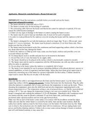
ELEMENTI SVILUPPATI APPOSITAMENTE PER COTTURA ALLA PIASTRA E PER<br />
PIANI CALDI. PROGETTAZIONE E SVILUPPO SPECIFICI PER OGNI ESIGENZA.<br />
ELEMENTS EXPRESSLY DEVELOPED FOR BARBECUE GRILLING AND HOT PLA-<br />
TES. SPECIFICALLY DESIGNED AND DEVELOPED TO MEET ANY REQUIREMENT.
ELEMENTI RISCALDANTI RADIANTI PER PIANI IN VETROCERAMICA<br />
RADIANT HEATING ELEMENTS FOR GLASS CERAMIC TOPS<br />
APPLICAZIONI PROFESSIONALI<br />
PROFESSIONAL APPLICATIONS<br />
temperatura (°C)<br />
temperature (°C)<br />
500<br />
450<br />
400<br />
350<br />
300<br />
250<br />
200<br />
150<br />
100<br />
50<br />
Questi elementi riscaldanti sono stati sviluppati appositamente per il<br />
settore professionale. Sono dimensionati per la cottura alla piastra o<br />
per piani caldi.<br />
Le potenze variano da 500w a 2500w a seconda della dimensione.<br />
Normalmente sono elementi monocircuito e la potenza viene modulata<br />
tramite un regolatore di energia, ma possono essere realizzati<br />
anche con due o tre circuiti. Sono prodotti che non hanno bisogno di<br />
limitatori di temperatura in quanto la temperatura del vetro rimane<br />
sempre abbondantemente al di sotto di 600 °C.<br />
Esiste una soluzione specifica per soddisfare la necessità di posizionare<br />
l‘elemento riscaldante in verticale o rovesciato.<br />
In ogni caso la progettazione e lo sviluppo vengono attuati in modo<br />
specifico, cercando di soddisfare qualsiasi esigenza ci venga sottoposta.<br />
Questa famiglia di prodotti è omologata VDE.<br />
These heating elements have been specifically developed for professional<br />
applications. Their dimensions are suitable for both grill<br />
cooking and hot plates.<br />
Powers range from 500W to 2500 W depending on the various<br />
dimensions available.<br />
Generally speaking, these are single-circuit elements, whose power<br />
is regulated by means of an energy regulating device, although they<br />
can also feature two or three circuits.<br />
These products do not require a temperature limiting device, as the<br />
temperature of the glass top is always below 600 °C.<br />
A specific solution to different requirements permits a vertical or<br />
upside-down positioning of the heating element.<br />
In any case, the elements are specifically designed and developed to<br />
meet any requirement by our customers.<br />
This family of products has received VDE approval.<br />
0<br />
0 1 2 3 4 5 6 7 8 9 10 11 12 13 14 15 16 17<br />
ANDAMENTO DELLA TEMPERATURA RILEVATA SULLA SUPERFICIE DEL FRY-TOP<br />
TEMPERATURE DEVELOPMENT MEASURED ON THE FRY-TOP’S SURFACE<br />
t. min.<br />
Min. t.
APPLICAZIONI SPECIALI<br />
SPECIAL APPLICATIONS<br />
BISTECCHIERE<br />
BARBECUE GRILL PANS<br />
FRIGGITRICI<br />
FRYERS<br />
Tra gli elementi riscaldanti per applicazioni speciali si possono annoverare<br />
generatori di vapore, riscaldatori per porta forno, scaldavivande, elementi<br />
per friggitrici e bistecchiere, celle catalitiche e resistenze per convettori ad<br />
accumulo (storage heater). Gli elementi per bistecchiere e friggitrici si<br />
caratterizzano per la fitta struttura a serpentina con raggi di curvatura molto<br />
stretti. Per entrambe le linee di prodotto la potenza mediamente sviluppata<br />
si agggira attorno ai 2000 Watt, mentre la diversa finalità di cottura implica<br />
un diverso intervallo di carico specifico: 4-6 Watt/cm 2 per la grigliatura<br />
barbeque, 5-7 Watt/cm 2 per le friggitrici. Le celle catalitiche rappresentano<br />
un complemento di sempre maggior diffusione al classico allestimento dei<br />
forni. Si tratta di dispositivi non funzionali alla cottura vera e propria ma di<br />
servizio a quest’ultima in quanto provvedono alla combustione, decomposizione<br />
e abbattimento della percezione olfattiva delle emissioni gassose<br />
prodotte dagli alimenti, e/o da eventuali incrostazioni di cibo presenti nella<br />
cavità del forno, in particolare nel caso in cui si proceda all’esecuzione di<br />
un ciclo di pirolisi autopulente della muffola. L’efficienza del processo di<br />
catalisi risulta fortemente condizionata dalla temperatura del gas drenato<br />
attraverso il filtro catalitico. Questi viene pertanto mantenuto alla corretta<br />
temperatura grazie al calore erogato da un elemento tubolare di modesto<br />
carico specifico e potenza (2.5 Watt/cm 2, 150 Watt). Gli elementi per storage<br />
heater trovano alloggiamento all’interno di blocchi in materiale refrattario<br />
cui cedono progressivamente il calore sviluppato. La potenza associata<br />
a ciascun elemento viene generalmente contenuta tra 1000 e 2000 Watt al<br />
fine di ottenere, in funzione dello sviluppo lineare dell’elemento, un carico<br />
specifico di guaina comunque compreso nell’intervallo 3.0-3.5 Watt/cm 2.<br />
In virtù delle particolari condizioni di scambio termico, tali valori risultano<br />
sufficienti a far assumere alla guaina della resistenza temperature spesso<br />
superiori agli 800 °C. Ciò richiedendo l’impiego di materiali ad alta prestazione<br />
quali l’AISI-309 o l’Incoloy 800.<br />
Heating elements for special applications include steam generators, heating<br />
elements for oven doors, food-warmers, elements for fryers and barbecue<br />
grill pans, catalytic cells and elements for storage heaters. The elements<br />
for barbecue grill pans and fryers have a distinguishing thick coil<br />
with narrow bending radii. Although both product types develop an average<br />
power of approximately 2000 Watts, their different cooking applications<br />
require a different specific load range: namely 4-6 Watt/cm2 and 5-7<br />
Watt/cm2 for barbecue grill pans and fryers respectively. Catalytic cells are<br />
becoming an increasingly popular accessory of standard-feature ovens.<br />
These devices are not functional with respect to the cooking function, but<br />
are complementary in that their tasks are related to combustion and<br />
decomposition as well as to the elimination of the smelling of gaseous<br />
emissions by food and/or by any food residue in the oven cavity, especially<br />
when a muffle self-cleaning pyrolisis cycle is carried out. The efficiency of<br />
the catalysis process is tightly dependant on the temperature of the gas<br />
drained by the catalytic filter. The gas is kept at the correct temperature<br />
thanks to the heat emitted by a tubular element with a low specific load<br />
(2.5 Watt/cm2 , 150 Watt). Elements for storage heaters are placed inside<br />
fire-proof blocks, which gradually absorb the heat developed by the element.<br />
The power associated with each element is usually ranging between<br />
1000 and 2000 Watts, in order to ensure that the sheath specific charge is<br />
always between 3.0 – 3.5 Watt/cm2, according to the element’s linear<br />
development. Thanks to special thermal exchange conditions, these values<br />
are enough to have the element’s sheath reach temperature levels that<br />
often exceed 800 °C. This requires the use of high-performance materials,<br />
such as AISI – 309 and Incoloy 800.
APPLICAZIONI SPECIALI<br />
SPECIAL APPLICATIONS<br />
GRILL IN MICROTUBO<br />
GRILL IN MICRO TUBE<br />
CATALIZZATORI<br />
CATALYSTS<br />
STORAGE HEATERS<br />
STORAGE HEATERS