Caution
Caution
Caution

Create successful ePaper yourself
Turn your PDF publications into a flip-book with our unique Google optimized e-Paper software.
Manuale d'officina<br />
Workshop manual<br />
ST4s<br />
Model Year 2001<br />
DUCATISPORTTOURINGf,
Sommario<br />
Contents<br />
3
Smontaggio coperture laterali<br />
cruscotto 66<br />
Smontaggio cupolino 67<br />
Smontaggio semicarenature inferion' 68<br />
Smontaggio semicarenature<br />
complete 68<br />
Smontaggio convogliatore tromste 70<br />
SoIlevamentoserbatoio carburante 70<br />
Smontaggio se-cercc carburante 71<br />
Smontaggio componenti serbatoio 72<br />
Smontaggio batteria 74<br />
Smontaggio supporto batteria 74<br />
Smontaggio sistema di scarico 75<br />
Smontaggiolevacomando cambia,<br />
coperchiopignone e nnviofrizione 76<br />
Smontaggio impianto di<br />
raffreddamento 76<br />
Smontaggio clacson e collegamenti<br />
etenrci eto sinistro 77<br />
Smontaggio col/egamenti etettno<br />
ere desrro 78<br />
Smontaggio tuba sfiato vapori<br />
basamento 79<br />
Smontaggio suooorto pompa <br />
pedale freno posteriore 79<br />
Smontaggio scarola filtro aria 80<br />
Smontaggio corpo farfallato 81<br />
Smontaggio couettote aspirazione 82<br />
Smontaggio pignone catena 82<br />
Smontaggio cavalletto laterale e<br />
centrale 83<br />
Smontaggio motore 84<br />
Smontaggio ruota anteriore 85<br />
Rimontaggio ruota anteriore 86<br />
Smontaggio ruota posteriot e 87<br />
Sostituzione della corona 88<br />
Lavaggiodella catena 89<br />
Lubrificazione della catena 89<br />
Dischi freno 90<br />
Rimontaggio roots posteriore 91<br />
Revisione ruota 92<br />
Smontaggio forcella anteriore 94<br />
Revisione forcella 95<br />
Sospensione posteriore 102<br />
Smontaggio e revisione forcellone<br />
asciI/ante 103<br />
Smontaggio ammortizzatore<br />
posteriore 105<br />
Sostituzione molla e iscenone<br />
ammortizzatore 105<br />
Smontaggio biella e bilanciere<br />
sospensione posteriore 106<br />
Revisiooe bilanciere sospensione<br />
posteriore 107<br />
Revisione tiranteammortizzatore 108<br />
Rimontaggio sospensione<br />
posteriore 109<br />
PinzlJ e pompe frena 110<br />
Posizionamento tubazioni frena 111<br />
Pompa e impianto frizione 113<br />
Ispezione impianto di<br />
raffreddamento motore 114<br />
Conuono del tetsio 115<br />
Sostituzione cuscinetti di sterzo 1/6<br />
Disposizione dei tubi e delle<br />
rrasmissioni flessiblJi sui relaio 118<br />
Coppie di serraggio mototelaio 126<br />
Motore 135<br />
Schema sequenza di smontaggio<br />
motore 139<br />
Smontaggio componenti motore 141<br />
Raising the fuel tank 70<br />
Removing the fuel tank 71<br />
Disassembling the fuel tank<br />
components 72<br />
Removing the battery 74<br />
Removing the battery mount 74<br />
Removing the exhaust system 75<br />
Removing the gear change lever, the<br />
sprocket cover and the clutch<br />
transmission 76<br />
Disconnecting the cooling<br />
system 76<br />
Removing the horn and<br />
disconnecting the LH electrical<br />
connections 77<br />
Disconnecting the RH electrical<br />
connections 78<br />
Disconnecting the breather ooo 79<br />
Removing rhe rear brake pedal and<br />
the cylinder support 79<br />
Removing the air box 80<br />
Removing the throttle body 8 1<br />
Removing the intake manifold 82<br />
Removing the chain sprocket 82<br />
Removing the side and the center<br />
stand 83<br />
Removing the engine 84<br />
Removing the front wheel 85<br />
Refitting the front wheel 86<br />
Removing the rear wheel 87<br />
Changing the rear sprocket 88<br />
Washing the chain 89<br />
Chain lubrication 89<br />
Brake discs 90<br />
Refitting the rear wheel 9 1<br />
Wheel overhaul 92<br />
Removing the front fork 94<br />
Front fork overhaul 95<br />
Rearsuspension 102<br />
Removing and overhauling the<br />
swingarm 103<br />
Removing the rear shock<br />
absorber 105<br />
Changing tho monoshock spring and<br />
checking the monoshock 105<br />
Removing the rear suspension<br />
connecting rod and rocker arm 106<br />
Rearsuspension rocker arm<br />
overhaul 107<br />
Monoshock linkage overhaul 108<br />
Refitting the roar suspension r09<br />
Brake calipers and master<br />
cylinders 110<br />
Brake hose routing 111<br />
Clutch master cylinder and hose<br />
routing 113<br />
Cooling system inspection 11 4<br />
Checking the framo 115<br />
Changing the steering head<br />
bearings 1/6<br />
Hose and ttexibto control<br />
routing 118<br />
Frame part torque settings 13 1<br />
Engine 135<br />
Engine disassembly sequence /40<br />
Engine disassembly 141<br />
General notes on engine overhaul 162<br />
Engino overhaul 163<br />
Engine lubrication circuit /8 1<br />
Lubrication diagram 183<br />
Oi/pump 184<br />
5
Indicazioni generali<br />
Description<br />
Indicaz;on; general; I Description 7
CONSIGUunU<br />
LD Ducati consiglia. onde prevenire<br />
inconvenienri e per if raggiungimento<br />
di un orrimo nsulta to finale. di<br />
attenersi genericamente aile<br />
seguenti norme:<br />
• in caso di una probabile<br />
riparaZlone valutare Ie<br />
impressioni del Clieme.<br />
evide nzianti<br />
anomalie di funzionamento del<br />
tr otoccto. e tomwere Ie<br />
opportune domande di<br />
chiarimento sui sint omi<br />
delf'inconveniente;<br />
• diagnosticare in modo cmsro Ie<br />
cause dell'anomalia. Dal txeseote<br />
manuale si potranno ssssmnere Ie<br />
basi teoriche fondam enrali, che<br />
peraltro dovranno essere<br />
integrate dall'e sperienza<br />
personale e dalla partecipazione<br />
ai corsi di addestramento<br />
organizzati periodicamente dalla<br />
Ducati;<br />
• pianificare renonetmente la<br />
nparazione onde ewtare tempi<br />
morti come ad esempio il<br />
prelievo di parti di ticsrnao, la<br />
preparazione degli ettrersi, ecc.;<br />
• raggiungere il particolare da<br />
riparare limitandosi aile<br />
operanoni essenria li:<br />
• a tale ptoposito sara di valido<br />
eiuto Ia consultB2ione della<br />
secu enre di smontaggio esposta<br />
nef pres eme manuale.<br />
A WORD OF ADVICE<br />
Ducati vvould like to suggest that you<br />
follow the instructions below so to<br />
ensure an effICient fault-free<br />
motoreycle opera tion.<br />
• VV1Jen diagnosing breakdowns,<br />
primary consideration should<br />
alw aySbe given to what the<br />
customer reoons. Your questions<br />
to the customer should aim at<br />
c/an'fying the problem .<br />
• Diagno se the problem<br />
svstemsticsllv and accurately<br />
before procee ding further. This<br />
manual provides the theoretical<br />
background for troubleshooting<br />
that shOuld be combined with<br />
personal experience and<br />
attendance at Ducati training<br />
courses.<br />
• Repair \o-\IClfk should be planned<br />
carefully in advance to prevent<br />
any unnecessary down-time, for<br />
eKampie picking-up of required<br />
spare pens or arrangement of<br />
required tools. etc.<br />
• Time and money can be saved by<br />
limiting the number of operations<br />
rooaea to reach the part to bo<br />
repaired.<br />
• The disassembly procedure in this<br />
manual describes the most<br />
efficient way to reach a part to be<br />
repaired.<br />
Indbdoni genenli I DeN:ription 9
12 Indicazioni flenenli I Description
Generalitii<br />
Description<br />
GenW'lllid I Description 13
SISTEMA OllNIUIONE<br />
/I sistema di iniezione e composto<br />
dei seguenti elementi:<br />
1) Centralina elerrronica<br />
2) Fusibile ao 20A<br />
3) Betteris<br />
4) Babina (una per cilindro)<br />
5) Eletrroiniettore (uno per cilindroJ<br />
6) Sensore temperatura/pressione<br />
assoJuta aria<br />
7) RegoJatore di press ione<br />
81 Potenziometro fartalla<br />
91 Ingranaggio condotto<br />
distribuzione<br />
10) Sensore temperatura acqua<br />
11)Pompabenzina<br />
12) Fittro benzina<br />
13) Commuratore a cneve<br />
14) Sensore motore<br />
15) Rele a teoura stagna<br />
16) Porrafusibile cia 54<br />
INJEcnON SYSTEM<br />
The injection system consists of the<br />
following:<br />
IJ Electronic control unit<br />
2) 20A Fuse<br />
3) Battery<br />
4) Coil (one each cyfinder)<br />
5J E/8C1.ric injector (one each<br />
cyfinderl<br />
6) Air temperature/absolute<br />
pressure sensor<br />
7) Pressure regula tor<br />
8) Throttle position sens or<br />
9) TImingdriven gear<br />
10J Water temperature sensor<br />
lJ1Fuelpump<br />
721 Fuel filt er<br />
73} Key-operated swi tch<br />
14} Engine sensor<br />
751 Wa rerproof relay<br />
76} SA fuse hokier
AUMENTAZIONE<br />
CARBURJlIIn<br />
I componenti dell'impianto di<br />
alimentazione carburame sono<br />
instal/ati su una flangia fissata scrrc<br />
al serba toio.<br />
L'impianto ecompos to da:<br />
1} Pompa elettrica<br />
2} Filtro carburante<br />
3} eceeeuo per tappa serbato io<br />
4} Degasatore<br />
5} Indicatore livello benzina<br />
5} Rego/atore di pressione<br />
7) Tappa settetoio<br />
a} Mandata<br />
b} Riromo<br />
c} Sfiato + drenaggio.<br />
FUEL SYSTEM<br />
Fuel system components are fitted<br />
onto a flange under the fuel tank.<br />
The fuel system consists of the<br />
following:<br />
1) Electric pump<br />
2) Fuel filter<br />
3) Filler cap recess<br />
4) Air separator<br />
5) Fuel sensor<br />
6) Pressure regulator<br />
7) Filler cap<br />
a) Delivery line<br />
b) Return line<br />
c) Breather and drain pipe .
l U BRI R CAZI ON E<br />
7<br />
I<br />
Farzara a meno pompa ad<br />
ingranaggi, con vallloia by-pass di<br />
sovrapressione, incorpora ta, rete di<br />
filtraggio in aspira7ionecartuccia<br />
inrercambiabile in mandata con<br />
valvola di sicurezzBper intasamemo<br />
della sressa indicatore bassa<br />
pressione sui ausco tto.<br />
L'impianto e composto 00:<br />
7) Raccordo tuba steto vapori<br />
coppa olio<br />
2} Tappo im mission e olio<br />
3) Indica/ore di livello<br />
4! Ingranaggi pompa olio<br />
5) Fi/tro a rete in aspirazione<br />
6} Pressostato<br />
7} Coppa olio<br />
8) cenucos (11((0 in man data<br />
9) Tubazionemeraete olio aile teste<br />
10) Raccordo teste orizzontale<br />
11) Raccordo tosta verticals<br />
12)Radiatore<br />
RAFFREDDAMENTO<br />
A liquido a arcuito pl8ssurinato con<br />
radiatore e teoroststo a<br />
m iscelazione. Una pompa centrifuga.<br />
COfTIdndara dall'albero di<br />
distlibuzio ne, mette in circolazione if<br />
liquido e un seteroo eli ospansione<br />
recupers Ie dila tazioni termiche del<br />
refrigerante.<br />
Capacita cncuno: 3,5 fitri<br />
Valore di pressione massima<br />
raggiung ibile prima delJ'apertura del<br />
tappa: 1.f<br />
Portata pompe:<br />
35 1/ min a 6.000 miIY'<br />
"<br />
LUBRlCA n ON<br />
10)<br />
Forced lubrication by gear pump.<br />
Mesh intake filter. Built-in pressure<br />
relie f by-pass valve. Disposable filter<br />
cartridge on inta ke w ith clogged<br />
canridge safety valve. Low oil<br />
pressure indicator on ins trument<br />
panel.<br />
The lubrica tion system consists of<br />
the following:<br />
1} Oil sump fumetbr"eather pipe<br />
2} Oil filler cap<br />
3} Oil level indicator<br />
4) Oilpump gears<br />
5JM esh intake fitter<br />
61 Pressure SWItch<br />
7} Oi/sump<br />
BJ Oilde livery filter cartMge<br />
9J Oil delivery tube to heads<br />
'OJHorizontal head fitting<br />
II} Vert ical head fitting<br />
12}Oil cooler<br />
COOUNG S YSTEM<br />
Fluid cooling through pressurized<br />
circuit with cooler and mixing<br />
thermostat. Cooem is pumped bya<br />
cenrn'tugal pump drive n by the<br />
camshaft.. The circuit has an<br />
expansion tan k to take up coolant<br />
lNfJen it expands (rom heat.<br />
Circuit capacity: 3.5 1<br />
Max. pre ssure value reachable<br />
before plug opening: f . f<br />
Pump flow rate:<br />
35 // m in at 6,000 rp m<br />
Generarrd / Description 19
Term ostat o<br />
Inizio soertua : 65 0C+J °c<br />
Pressione massima del circuito di<br />
raffreddamento: A tm 1,1<br />
Inserzione elettroventola: 103 °C<br />
Diserzione e/ettroventoo: 702 °C<br />
Controllo con centralina:<br />
MARELU5.9<br />
J'HASMISSIONE<br />
Primaria<br />
lid ingranagg; trtritti.<br />
Rapporto di tsesrmssione: f.lU<br />
Frizione a secco a dischi mulripl;:<br />
8 condom (7piani + 7bombato) + ]<br />
oonduttori con 14 superfici di attnto;<br />
6 moI/e e/icoidali di pression e.<br />
Comandata ria un circuiroidraulico<br />
azionato da una leva suneto sinistro<br />
del manubria. Trasmissione fra<br />
motore e a/bero primario del cambia<br />
ad ingranaggi a denri dintti.<br />
Meccanismo di sefezione de/fe<br />
marce con tamburo e force /Ie. Una<br />
leva arrico1atacomanda /a rotazione<br />
del tamburo.<br />
Cambio a 6 rsoocai.<br />
Secondaria<br />
Pignon e uscita cambio n° 15 dent;<br />
Corona posteriore nO43 dent;<br />
RlIpporli tota';<br />
"<br />
37/15 12,70<br />
2' 30/17 9,09<br />
3' 27/20 6,95<br />
4' 24/22 5,62<br />
5' 23/24 4,93<br />
6' 24/2B 4.41<br />
Trasmissione fin;;le meoente<br />
ceteoe:<br />
DID<br />
too:<br />
525 HV<br />
Dimensioni (passo x /arghezza<br />
imeme tra le piastrine)<br />
5/S" (15,S] 5 m m ) x5/16" (7,93<br />
m ml<br />
oemetro de; perni:<br />
10,16mm<br />
,.,. maglie:<br />
'02<br />
Thermostat<br />
Open ing start: 65 °C±2 °C<br />
Coo/ing syStem max. pressure:<br />
1.1 Atm<br />
Elecrric fan connection: 703°C<br />
Electric fan disconnection: 102 °C<br />
Control/ed by MAREW 5.9 con trol<br />
Unit.<br />
TRANSMISSION<br />
Prim-r drive<br />
through . pur p ars.<br />
Drive rario: 1.84<br />
Dry multi-plate clu tch: S driven plares<br />
(7 flat + 1 con veJQ + 7 drive plares<br />
\o\IIrtl 74 fric tion surfaces. 6 pressure<br />
coil springs.<br />
Clutch is hydraulically controlled by a<br />
lever onthe LH handlebar. Primary<br />
drive berween gearbox mainshaft<br />
and engine by spur gears. Selecror<br />
drum and fork gear seector system.<br />
A lever linkage controls selector<br />
drum rotation.<br />
6-spe ed gearbox.<br />
Second.'Y drl_<br />
15-tooth gearbox output sprocket<br />
43-tooth rBar sprocket<br />
'" 37/15 72.70<br />
2'" 30/ 17 9.09<br />
3" 27/20 6.95<br />
4"<br />
..<br />
24/22<br />
23/24<br />
5.62<br />
4.93<br />
e- 24/2S 4.4 1<br />
Final dove from gearbox to rear<br />
wheel by chain:<br />
DID<br />
Type:<br />
525 HV<br />
Dimensions (pitch x inside width<br />
between side plates)<br />
5/S " (15.S75 mm) x 5/16"'{].93<br />
mml<br />
Pin diame ter:<br />
10.16 mm<br />
No. of links:<br />
'02
PNEUMATICI TYRES<br />
AD t eriore Front<br />
Struttura: Type:<br />
radiale tipo "tubeless" radial. tubeless<br />
DImenslone: Size:<br />
120170-ZR 17 120170-ZR17<br />
120/65-ZR17 120/65·ZR77<br />
Posteriore Rear<br />
Struttura: Type:<br />
radiale tipo "tubeless" radial, tubeless<br />
Dimensione: Sire:<br />
180/55-ZR17 780/55 - ZR1 7<br />
190/50-ZR17 190/50-ZR77<br />
Pressione B" Kg/em' Tyro B" Kg/sq, om<br />
pneumatici p ressure<br />
(a treddo} (cold}<br />
Can pilota + With rider +<br />
bagagfio<br />
luggage<br />
Anteriore: 2,1 2,3 Front: 2.1 2.3<br />
Posteriore: 2,2 2,4 Rear: 2.2 2.4<br />
Can pilota +<br />
passeggero +<br />
With rider +<br />
pillion rider +<br />
B" Kgjsq,em<br />
bagaglio<br />
luggage<br />
Anteriore: 2,4 2,5 Front: 2.4 2.5<br />
Posteriore: 2,B 2,S Rear: 2.B 2.S<br />
[] Importante<br />
In easo di sosnnecoe del<br />
pneuma tico si consiglia di utiliLZare<br />
marea e teo di primo<br />
equipaggiamemo. Misura re la<br />
pressione dei pneumatiei quando<br />
essi sono freddi,<br />
AI fine di salvaguardare te rotondita<br />
del eerehio anteriore pereorrendo<br />
strade mol to seonnesse aumentare<br />
la pressione di gonfiaggio del<br />
pneuma rico di 0,2+0,3 bar.<br />
[] <strong>Caution</strong><br />
When changing tvres alwa :ys<br />
fit the original make and type rwes.<br />
Measure tyre pressure when the<br />
tvres are cold.<br />
To prevent front wheel rim damage<br />
when riding on rough roads, increase<br />
front tyre pressure by 0.2 -0.3 ber.<br />
GeneralitS / Description 23
24 G fMttral;d / Description<br />
INlPIANTO ELETTRICO<br />
Formato dai seguenti panico /an'<br />
principali:<br />
Proiettore anteriore<br />
composto da:<br />
unita anabbagliante poIiellissoidiJle<br />
a condensatore 12-55W;·<br />
uni:a abbagfiante 12-55W;<br />
luce di posizione con lampada<br />
12·5W.<br />
Cruscotto. lampade spia 12· 1,.2W 8<br />
lampade illuminazione smrreoto 12·<br />
2,,3W.<br />
Comandi elettrici sui manubrio.<br />
Indica tori direzione. lampade 12lOW.<br />
AvviSlJtore acustico.<br />
Interrvttori Iud B"esto<br />
Batteria , 12· 10Ah.<br />
AltemBtore 12-520W.<br />
RegolBtore e'ettronico. tro tetto<br />
con fusibiJe da 40 A<br />
Motorino avviamento. 12V4J.7<br />
.w.<br />
Fansle posteriore, Iampada doppio<br />
fifamento 12-5/ 2 1W per<br />
segnalazione arresto e luce<br />
posizione; lampada 12-5W per<br />
ilJuminazione targa.<br />
PRE$TAZIONI<br />
Velocita max. (solo conduttore):<br />
255 Km/h<br />
PESI<br />
In ordine di marcia (senzabenzina):<br />
215 Kg<br />
anteriore:<br />
104 Kg<br />
posteriore:<br />
lOB Kg<br />
A pieno carico:<br />
420 Kg<br />
ELECTRICA L SYSTEM<br />
Main components :<br />
Front helldlight<br />
consisting of:<br />
12 -55W po!y-elfipsoidal low beam<br />
lamp, with capacitor;<br />
12·55W high beam lamp;<br />
parting lIght wi th 12-5W bulb.<br />
Instrumflntpanfil. 12-1.2W warning<br />
lights; 12-2 and 3W instrument<br />
lights.<br />
Electric contro's on handlebar.<br />
Turn indicator lamps: 12·10W.<br />
Hom.<br />
Stop light switches<br />
Battery 12-10 Ah.<br />
Genet'ator 12-520W.<br />
Electronic rectifittr. protected by a<br />
40A fuse.<br />
StarttH motor. 12V -D.7 kW<br />
Taillight. 12-5/21W double-filament<br />
bulb for stop and parting lights; 12·<br />
5Wbulb toe number plate light.<br />
PERFORMANCE<br />
Max. speed (rider only):<br />
255 Kph<br />
WEIGHT<br />
In travel direction (without fuel):<br />
2 15 Kg<br />
Front:<br />
104 Kg<br />
Rear:<br />
l OB Kg<br />
Full load:<br />
420 Kg
INGOM BRI (mm) OVERAU DIM ENSIO NS (mm)<br />
1430<br />
2070<br />
I I<br />
I I<br />
Generalita / Description 25
Manutenzione<br />
Maintenance<br />
Manutenzione / Maintenance 29
Operaz;on;<br />
Llvello olio motore<br />
Olio motore<br />
Fillro olio morore<br />
httro asp;razlone 0110 morore<br />
Gioco va/vole motore<br />
Cinghle dtstrlbuzione (7J<br />
Csnaete<br />
Uvello liquido raffreddamenro<br />
sosuuuooe liquido raffre ddamenro<br />
Filrro carburanre<br />
Corpo farialJato: sincronizzazione e minima<br />
Fillro aria<br />
Pressione olio matore<br />
Compression e cilindri motore<br />
Olio comando freni e treooe<br />
Cornandi idrauJicl freni e frizione<br />
Pneumatici: usura e pressione<br />
Giococuscinetti steao<br />
Carena: rensionamenro e lubri fic8zione<br />
Usura pastiglie freno<br />
Serbatoio benzina<br />
Sostltuzione olio forcella anr. (1)<br />
Lubrificazlone e ingrassaggio generaJe<br />
Conrrollo impianro rcerce bat/ena<br />
c<br />
c<br />
c<br />
s<br />
s<br />
c<br />
c<br />
Ogn;<br />
1000<br />
km<br />
c<br />
Comrouo serraggio punti critici per la sicurezza C<br />
dinamica del vecoo (21<br />
Col/audo genera le del ve/COlO (3) C<br />
Pu/izia generate P<br />
c<br />
c<br />
c<br />
c<br />
c<br />
Ogn;<br />
10000<br />
km<br />
s<br />
s<br />
c<br />
c<br />
s<br />
s<br />
c<br />
Ogni<br />
20
Operlltion 5 Pre- Aher first Ev"'Y Every Every Every<br />
delivery 7.000 km 1,()(J(J fO,Ooo 20,000 30,000<br />
km km km km<br />
Engine oil level C C<br />
Engine oil 5 5<br />
Engine oil filrer 5 5<br />
Engine oil intake filt er CIT'<br />
Valve clearance C<br />
Timing beltS ( f ) C C 5<br />
Spark plugs 5<br />
Coolant level C<br />
Change coolant 5<br />
Fuel filter 5<br />
Throttle body: timing and idling C<br />
Air filter 5<br />
Engine oil pressure C<br />
Engine cylinder compression C<br />
Clutch and brake fluid level C 5<br />
Clutch and brake hydraulic controls C C<br />
Tyres: w ear and pres sure C C<br />
Steering bearing play C<br />
Chain tension and lubrication GIL<br />
Brake pad wear C<br />
Fuel tank P<br />
Change front fork oil (I) 5<br />
Genera/lubrication L<br />
Check battery charging syStem C C<br />
Check tighte ning of weak soms for C<br />
vehicle dynamic safety (2)<br />
General tes ring (3} C<br />
General cleaning P<br />
N o te<br />
f } Replace every rwo years, in any case<br />
21 Check for proper tightening of the following safety parts; if improperly rightened . please refer to tight ening<br />
torque tables in workshop manuals.<br />
3! Test the following parts :<br />
Vv1lee/ hub bearings<br />
Rear wtJeffl spring joint<br />
Piston retaining plate<br />
M iddle and side stand<br />
Indication and lighting devices<br />
32 "'..nmenDon. I Maintenanc e
CONTROLLO UVELLO OLIO<br />
MOTORE<br />
lliwello delf'oIio nel motore If visibile<br />
attraverso l'obIO m di ispezion e costa<br />
sousto cestro della coppa olio.<br />
a Attendere qualche menno dopa 10<br />
spegnimenro affinchtJ i/ fwe llo si<br />
srabifizzi.<br />
a cowossro if fiveffo con if vecooin<br />
posizione perte nsmente verticale sui<br />
ca vaserrc centrale e con motore caldo<br />
(rna spentot.<br />
a II fivello deve manrenersi us te<br />
tacche 3 e ,f.in corrispon denza<br />
dell'obIo stesso. indicanti<br />
tispeuivsmente i1livello massimo e<br />
minimo dell 'olio.<br />
o Se illivello risulta scarso 8<br />
necessario procedere 81rabbocco<br />
dopo aver rimosso 18 semicarenatura<br />
inferiore destra (vedi paragrafo<br />
HSmontaggio semicarenature<br />
inferiori w al capitola -Motote/aio - ).<br />
o Rnraovete il tappa di carico (2) e<br />
aggiungere olio prescritto fino a<br />
raggiungere if livetto stabifito .<br />
a Richiudere il serbatoio e rimontare<br />
Ie strurture rimosse.<br />
CDIIf1l0LLO PflESSIONE DUO<br />
IIM1TOIlE<br />
Perconrrol/are Iapressione deN'oIio<br />
moure enecessaria scoIlegare fa<br />
connessione (5) sui pressostato 16}.<br />
Svitare e rim(J(]V(Jfe iItxessosts to (6) ed<br />
awirare netforo filerrato, sededel<br />
pressostato (Ml0 x I), if raccordo (7)<br />
coIlegato al manometro (8). Effettuando<br />
iI ccatrouo a motore freddo, si rilevera<br />
il valore di pressione piu eteveto, in<br />
quanto la cJensitiJ delrolio epiu alta.<br />
La pressione non dovra mai risul tare<br />
superiore a 6 bar,<br />
Valori di controno pressione olio:<br />
• M at are freddo:<br />
1100+1300 m in"<br />
maggiore di 2,5 bar<br />
3500+4000 mirr'<br />
compreso tra " e 6 bar<br />
• Matare calda (I 4f1'C).<br />
1100+1300 min"<br />
maggiore di 1, 1 bar<br />
3500+4000 min"<br />
compreso trs " e 6 bar<br />
Una pressiooe troppO elevata puO<br />
significare un inceppamento defla<br />
vai'vola imiratrice. AJconrrario, U1l vafore<br />
rroppo basso puO eSS8fB ceoserc dalla<br />
valvolalimitatricel:bx:ara neifa<br />
posizione di aperrura. da una moI/a<br />
troppo tenera 0 da una pompa<br />
otenose Mre cause poss ono essere<br />
una usura eccessiva delle guamizioni di<br />
tenuta 0 del motore stesso.<br />
Rimuovere I'attrezzatura e nmontare il<br />
oressosuto, btcccsraoto alia coppia<br />
di se"aggio prescritta (vedi capitolo<br />
'Copoie di se"aggio· selione<br />
'M otore";'<br />
CHECKING THE ENGINE OIl.<br />
LEIIEL<br />
Check the engine ail level on the<br />
sight glass (7) on the RH side of th e<br />
oil sump.<br />
a After switching off, allow the oil to<br />
settle for several m inu tes before<br />
checking the level.<br />
a Check the level with me<br />
motorcyde raised Ofl lts center<br />
sta nd, perfectly vertica l and with the<br />
engine hot (but off).<br />
o The ail must be between the 3<br />
and" notches marked alongside the<br />
sight glass, indicating max. and min.<br />
level.<br />
a To top up (in case of low oil leve l),<br />
remove the lower RH fairing (see<br />
HRemoving the lower fairings H,<br />
under sec tion "Frame-).<br />
o Remove the filler plug (2) and top<br />
up WIth the recommended oil.<br />
a Close the tank and fit all parts<br />
previously rem oved.<br />
CHECIUNG M E ENGINE 011'..<br />
I'frESSURJ!<br />
To check the engine oil pressure,<br />
disconnect 15} the pressure switch<br />
(61. Remove the pr essure switch (61<br />
and rhen fir the connector (7)<br />
con nected with the pressure gauge<br />
(8) to the threaded hole (M JOx I 1. the<br />
pressure sw itch seat. Whe n the<br />
engine is cold the oil will be thicker<br />
and the pressure reading obtained<br />
will therefore be high er.<br />
The maximum pressure must not<br />
exceed 6 bar.<br />
Oil pressure test values:<br />
• Cold engin6:<br />
at 1, 100 ·1,300 rpm<br />
above 2.5 bar;<br />
at 3,500 -4,000 rpm<br />
between " and 6 bar.<br />
• Hot engin e (f4d'C):<br />
at 1.100 ·1,300 rpm<br />
above 1. I bar;<br />
at 3,500-4,000 tpm<br />
between " and 6 bar.<br />
A pressure which is too high<br />
indicares that the pressure reducing<br />
valve is jamming. A pressure which<br />
is too low indica tes that the pr essure<br />
reducing valve is jammed in the<br />
open position, tha t the spring is too<br />
weak, or rhat rhe oil pump is faulty.<br />
Other causes of faulty pressure<br />
readings include: oodly worn seals<br />
and gaskets; badly worn engine.<br />
Remove the test equipment. Refit<br />
and tighten pressure switch to<br />
specified torque (see paragraph<br />
l orque figures· under section<br />
"Engine'").<br />
M .."utenzione / Msi"t...S"C6' 33
36 IfIfanunnzione I Maintenance<br />
CONTROUO COMPRE$SIONE<br />
CIUNDRI MOTORE<br />
/I rendimento del motore e<br />
direnameme corre/ato con it vetoee di<br />
pressione che si puo m isurare nelle<br />
camere di combustione dei due<br />
gruppi termici. Una pressione<br />
eccessiva od insufficien te, cosi<br />
come una eccessiva differenza tra i<br />
due cilindri, produce sicuramente un<br />
csto presrazionale del motore e puO<br />
esse re causa di roture.<br />
Per effe rtuare ccestc conrrolJo e<br />
necessario disporre di uno<br />
strumemo di misura eoetto<br />
(MATHESIS 0 analoghi1, m unito di<br />
adartarore per I'installazion e nella<br />
sede cande la.<br />
o Verificare che fabarteria risulti<br />
carica (almena 12,5 V n'levati<br />
direnamente sui terminali, senza<br />
cercol.<br />
o Riscaldare it motore fasciandolo<br />
in funzione fino all'inserimento.<br />
almena una vote.<br />
riell'elettrovenrola.<br />
o Spegnere 11 motore.<br />
o Rimuovere Ie csrxiete, utilinando<br />
guanti con tro Ie scottsture.<br />
• Attenzione<br />
[lJ Mette re il commutator e destro<br />
in posizione 'OFF ' per togJiere<br />
tensione alia candela.<br />
o Awitare nella sede del cilindro da<br />
control/are I'adatratore e collegare 10<br />
strumento di misura.<br />
o Aprire com p/etameme te terts ne.<br />
o Far girare i/ m orore con il motorino<br />
aw iam enro fino el ouato in cui la<br />
pressione non aumenta oo.<br />
• Control/a re la pressiore in ogni<br />
cilindro:<br />
valore standard' 9+ 11 bar;<br />
vetore minimo: 8 bar;<br />
differenza massima acce rtabile<br />
rra i cilindri: 2 bar.<br />
Un vetore di pressione eccessivo ooo<br />
ess ere causato ae:<br />
incrostazioni presenti nella<br />
camera di combusrione.<br />
Un valore di pressione troooo basso<br />
puG essere causato cia:<br />
perdita di gas tra testa e cilindro;<br />
sedi valvola usura te;<br />
guida vaJvole usurate;<br />
steli valvola distorT.i;<br />
gioco valvole sconeno:<br />
cilindro 0 segmenti usurati.<br />
CHECKING THE CYUNDER<br />
COMPRESSION<br />
The performance and efficiency of<br />
an engine are directly linked to the<br />
comptession inside the comb ustion<br />
chambers of the two eyfinders.<br />
Complession which is too high!low<br />
or a large compression difference<br />
between the two cyfinders will<br />
cause a drop in engine performance<br />
and can cause engine breakdowns.<br />
To check the compression you w ill<br />
require a suitable tester (e.g.<br />
MATHESIS or similarJandan adapter<br />
for fitting rhe rester ro rhe spark plug<br />
hole.<br />
o Check that the battery is charged.<br />
Under no-load conditionS. the re must<br />
be a charge of at least 12.5 V<br />
measured at the terminals.<br />
o Stan the engine and allow it to<br />
warm up , Wait until the electric fan<br />
SWItches onat leas t once.<br />
o Stop the engine.<br />
o Remove the spark plugs. Wear<br />
safety gloves.<br />
• Warning<br />
[lJ Turn the RH switch to OFF to<br />
clear the spark plug.<br />
a Screw the adapter into the spark<br />
plug hole of the cvunaor to be tested<br />
and connect the tester.<br />
o Open the throWes ful/y.<br />
o Turn rhe engine over using the<br />
srerre-motor until the pressure<br />
reading stops rising.<br />
• Check rhe com pres sion of both<br />
c ylinders,<br />
Standard compression: 9 -11 bar<br />
Min imum compression: 8 bar<br />
Maximum aI/owed compression<br />
difference betwe en cYlinders: 2<br />
"',<br />
Excessively high compression<br />
readings indicate the following:<br />
depos its in the combustion<br />
chamber.<br />
Low compression readings indicate:<br />
gas leakage between head and<br />
eyfinder;<br />
worn valve seats;<br />
worn valve guides;<br />
bent valve stems;<br />
incorrect valve clearances;<br />
wom eyfinders Of piston rings.
Registrazioni e regolazioni<br />
Settings and adjustments<br />
Registr.uioni • regoIaDoni I Settings lind .dju5fnrents 45
'--<br />
CONTROLLO GIDeD VALVOLE<br />
Per cater eseguire te ope razioni dl<br />
comiouo e registrazion e del gioco<br />
valvole enecessaria smontare tutti<br />
qu e; component; de l morociclo che<br />
possono cszacozare 0 impedire<br />
J'ope razion e in corso.<br />
" N o te<br />
4->c, Per una m iglior comprensione<br />
Ie figure mosu ano una testa rimossa<br />
dalmorore.<br />
Per peter operare sune valvole e<br />
necessariarimuovere iI setetoo. 18<br />
scstoe tinroe i/ corpo tertsus to. Per<br />
rim uovere j coperchi delle cinghie<br />
della distribuzione e necessario<br />
stsccsre 18 batreria e il porta batteria<br />
lasciando tutti gil uri/inaton"coi/egari.<br />
Tune quesre operazion i sana<br />
descrine al capitola ·Operazior!i<br />
generali". Le o;Jerazion i rsffigurare e<br />
Ie relative descrizioni di questa<br />
paragrafo si rdenscooo alia testa<br />
verticete; i/ medesimo procedimento<br />
!iovra essere eseguito anche per /a<br />
testa orizzonraJe. Dopo aver rimosso<br />
iI coperchio di ispezione (,) agenda<br />
sulle quanta viti (A), con uno<br />
spe ss imetro venticere i/ gioco<br />
eseteme. Con valvola in posizione di<br />
riposo infilare la lama dello<br />
soessimetra tra bilanc iere di apertura<br />
e registro; contemporaneamente<br />
fare leva co n un giravite fB} sott o alia<br />
torcnetts de l bnenciere di chiusura.<br />
/I gioco deve rentrete nei valori<br />
prescntti:<br />
Bilanciere di aperture:<br />
Aspirazione: mm<br />
Lim ite<br />
Scsrco: mm<br />
Limite<br />
Bilan ciere di chius ura:<br />
A sp irazione: mm<br />
Limite<br />
Scarico:mm<br />
Limite<br />
0,16 -t--O, 18<br />
0,05<br />
0,16 + 0, 18<br />
0,05<br />
0,21 + 0,23<br />
0.25<br />
0,11 + 0, 13<br />
0.20<br />
Se i valon riscon rrati nsunsro fuori<br />
dai limiti prescrirri procedere alia<br />
registrazion e come descritto al<br />
paragrafo scccessvc.<br />
46 Registrazionl . regogzioni I Settings and adjustznents<br />
CHECKING VALVE<br />
CLEARANCES<br />
To check and adjust valve clearance s<br />
it will first be necessary to remove<br />
all those compOnents which obstruct<br />
access to valve com ponents.<br />
Iii' Nore<br />
tIiiiII Fot reason s of d stity. the<br />
figures show the eyiinder head<br />
removed from the engine .<br />
To reach the valves, remove the fuel<br />
tank. the air box and the throttle<br />
body firs t. To remove the timing belt<br />
covers. disconnect the battery and<br />
the battery hokier leaving all items<br />
con nected. All these operations are<br />
described under section ·GENERAL<br />
OPERA TIONS·. Procedures and<br />
figures co ntained in this paragraph<br />
relate to the verrica l head; repeat the<br />
same procedures on the horiZon tal<br />
headas well.<br />
Undo the four screws (A) to remove<br />
the inspection co ver (I). Check<br />
clearance using a feeler gauge .<br />
With the valve in rest position, fit the<br />
feeler gauge between ope ning<br />
roc ker arm and opening shim. At the<br />
sam e tim e, lever with a screwdriver<br />
(8Jplaced under the clos ing rock er<br />
fork . Values must be as follo ws:<br />
Opening rocker arm:<br />
Intake: mm<br />
Limit<br />
Exhaust: mm<br />
Limit<br />
Closing rocker arm:<br />
Intake: mm<br />
Limit<br />
Exhaus t: m m<br />
Limit<br />
0. 16 -0.18<br />
0.05<br />
0.16 -0. 18<br />
0.05<br />
0.21 · 0.23<br />
0.25<br />
0.11 - 0.13<br />
0.20<br />
If the clearances m easured are no t<br />
WIthin the specified limits, adjust<br />
following the ins tructions in the next<br />
paragraph.
88173.0862<br />
G;oco di chiusura 56 il gioco tra bilanciere infen'ore e<br />
scodeflino risuns scarso 0<br />
abbondante e necessaria. per poter<br />
sostituire 10scodellino (scala da 2,1 a<br />
3,1 mm), rimoovere r albero a<br />
camme procedendo in questa modo:<br />
o Rimuovere iI coperchierto (2)<br />
agenda sulle viti (3).<br />
o Rimuovere i coperchi (B, Ce D}<br />
della distribuzione agendo sufle<br />
relative viti (1).<br />
o Sfilare compleramente i pem i del<br />
biJancien'superiori utilizzandO<br />
rettreao cod. 88173.0862_<br />
o Svitare Ie due viti di fissaggio (4} e<br />
sfilare il soooxto campleto di<br />
puleggia e a/bero a camme OOllato<br />
destro. Sfilare i biiancien' superiori<br />
dalr interno de lla tes ts.<br />
a Portare ;1 pistone al P.M.$. per<br />
evitare cne fa valvo/a priva eli n'tegno<br />
cada all 'inrerno del cilindro.<br />
Con dovuta cautela, mserire un<br />
perno di alluminio dafl'apertura de l<br />
sooooto albero a camme facendolo<br />
passare dietro al partino (AJ; spingere<br />
quest'ultimo verso r est emo e,<br />
mantenendola in questa posizione,<br />
sfiJare 10 scodeJlino di ritorno (5} e i<br />
due semianelli (6) dal gambo della<br />
valvola.<br />
C '-,..........<br />
E oooonuno inserire uno<br />
strecco sotto aile leve dei bilancieri<br />
per evitare ai semianelli (6) di cadere<br />
slt'mtem o de i conaotti di scolo olio.<br />
a Controllare 10 spessore dello<br />
scodellino utilizzando reocosno<br />
calibro cod. 88165.0918 e un<br />
comosrstore inseriro su un soooo no<br />
a colonna {com e mostra la figural.<br />
o Misurare t'sneae della spalla<br />
dello scodellino.<br />
Clos;ng clearance<br />
If clearance berween lo w er rocker<br />
arm and closing shim is too sma ll or<br />
too large, remove rhe camshaft to<br />
rep/aaJ the closing shim (2.1 t0 3.1<br />
mm range) . Proceed as fo/lows:<br />
o Undo the screws (3) and remove<br />
the cover {21.<br />
o Undo the SCf8WS (1} and remove<br />
the tim ing covers (8, C and D}.<br />
a Remove the upper rocker arm<br />
shafts using the tool part no.<br />
88113.0862.<br />
o Undo the rwo fastening screws<br />
(4) and remove the support complete<br />
WIth timing belt roller and camshaft<br />
from the righr side. Remove the<br />
upper rock er arms from inside the<br />
he'"<br />
a Move the piston ro the T.D.C<br />
{otherwise the loose valve would fall<br />
into the cylinder}.<br />
Gently fit an aluminum aritt into the<br />
opening of the camshaft support and<br />
slide behind sliding shoe (AJ. Push<br />
sliding shoe outwards and keep it in<br />
rhis position. Remove the rerum<br />
spring cap (5) and txnn split rings (6)<br />
from valve stem.<br />
C c.ution<br />
Pur a cloth under rhe rock ers<br />
to prevent the split rings (6) from<br />
falling into the oil scavenge holes.<br />
o Check the shim thickness with<br />
the gauge part no. 88165.0918 and a<br />
dial gauge tmed on a srand supp ort<br />
(as shown in the figure).<br />
o Measure the shim shoulder<br />
thickness.
o Collegare il cavo di alimentazione<br />
del "MATHESIS" (RC 582) alia<br />
tetteas della mo ta e al connerrore a<br />
3 vie del cavo saettetore<br />
autodiagnosi PAKARD IPF A 607).<br />
o Connenere iI csvo adattatore<br />
autodiagnosi PAKARD al cava<br />
adattatore autodiagnosi CDS mc<br />
586} e col/egare quest'ultimo alia<br />
porta centrale dello strumento.<br />
o Col/egare il cevoadattatore per<br />
potenziometro (PF A 615) aI/a porta<br />
COM 2 dello strumento e al<br />
potenziometro del cotoo terteseto.<br />
o Introdurre la "Memory card",<br />
entrare nella tunzione potenziometro<br />
(F4) e veriticere sullo strumento iI<br />
vetoredi 150 m V±15,<br />
a In caso di vetoi different):<br />
enootere Ie 2 viti (3) di fissaggio<br />
potermometro e. mantenendo in<br />
posizione dl chiusura la farialla<br />
MASTER, rootsre il potenziometro<br />
fino a leggere sullo strument o il<br />
valore pre scritto.<br />
o Serrare Ie viti (3) del<br />
potenziometro quindi staccare la<br />
connessione del "MATHESIS" aet<br />
potenziometro e riconnettere il<br />
cablaggio della moto.<br />
o Se e stato staccato, inserire iJ<br />
terminale del cavo di comando<br />
acceleratore nella carrucola per<br />
ettivete iI comando e registrare /a<br />
corsa seguendo Ie indicazioni<br />
riportete et paragrafo "Regolazione<br />
csvi di comsndo acceleratore e<br />
starter'.<br />
o Collegare il vacuometro si<br />
collettori aspirazione dopo aver<br />
rimosso te vite che chiude il foro di<br />
applicazione del raccordo dello<br />
strumento.<br />
o Chiudere completamente to viti (4)<br />
at by-pass.<br />
o Avviare la moto e mantenerla<br />
/eggermente acceerers.<br />
o Silandare la depressione nei<br />
condotti di aspirazione agendo sui<br />
pomello (2) de l tirsnte di<br />
collegamonto delle due teitsue.<br />
o Col/egare 10strumento<br />
'M A THESIS' alia presa di diagnosi,<br />
Entrare nel menu autodiagnosi (F1) e<br />
scegliere la turaooe lettura parametri<br />
IF1} poi. con te frecce (II) seteeionsre<br />
la fines tra mV - gradi.<br />
o Agire sulla vite di registro (1)<br />
MASTER, fino a leggere sullo<br />
strumento un vetore di:<br />
US,A = 2,3" mV403<br />
EU =1,8"mV345<br />
CH =2.3 ° mV403<br />
a Rimontare tutte Ie strutture<br />
rimosse.<br />
o AI/entare poi Ie viti (4) di by-pass at<br />
ogni cilindro, fino ad ottenere un<br />
regime minima di 100()+- 1100 m in" ,<br />
can ooaste a'eae bitenciete.<br />
tester and to the sensor on the<br />
throttle body,<br />
o Insert the memory card in the<br />
tester and access the throttle<br />
position sensor IF4) function. You<br />
should get a reading of 150m V:!::15.<br />
o In case a different value is read,<br />
loosen the 2 screws (3) retaining' the<br />
throttle position sensor, keep toe<br />
MASTER throttle closed and tum the<br />
throttle position sensor until you<br />
obtain the required reading.<br />
o Tighten the throttle position<br />
sensor screws (3). Disconnect the<br />
"MATHESIS" tester from the sensor<br />
and reconnect bik e Wiring.<br />
a If you disconnected the throWe<br />
control cable previously. now<br />
reconnect the cable end to the cam<br />
pulley and adjust the cable travel as<br />
indicated in the paragraph" Adjusting<br />
the throttle and choke cables N.<br />
a Remove the screw on the<br />
vacuometer connector hole and<br />
conn ect the vacuometer to the<br />
intake manifolds.<br />
a Ful/y tighten and close the by-pass<br />
screws (4),<br />
o Start the engine and run it slightly<br />
fast.<br />
a Balance the vacuum in the int.9ke<br />
ducts by turning the knob (2) on the<br />
throttle linkage.<br />
o Connect the "MATHES/S' tester to<br />
the self-diagnosis outlet. Access the<br />
self-diagnosis menu IF 1)and setect<br />
the parameter reading function (F 1).<br />
Press the arrow keys (tt) to select<br />
the window rnV-degrees.<br />
o Turn the MASTER adjuster (1)<br />
until reading a value of:<br />
US,A = 2.3 " mV 403<br />
fU= 1,8°mV345<br />
CH =2.3"mV403<br />
o Refit all parts previously removed,<br />
o Loosen the by-pass screws 14.1 for<br />
each cylinder until you obtain an<br />
idling speed of 1.000 -1.100 rpm<br />
with balanced air flow.<br />
Registrazioni e regolazioni / Settings and adjustments 51
60 Regis trarion i " regolazioni I S e tting s and adjustments
Mototelaio<br />
Frame<br />
M ototelaio / Franlc, 61
2<br />
3)--- -1-<br />
,<br />
5<br />
62 Mo totrlaio I ham.<br />
/ ]<br />
6)--- -+<br />
7<br />
II<br />
12
66 Mototelalo I FnJ",.<br />
SMONTAGGIO COPERTVRE<br />
LATERAU CRUSCOrro<br />
Ouesti etem enti sene nsseti ua Ioro<br />
ae una vite cemra le (A) e alia<br />
ccoerrwa interne del cupolino ce una<br />
seconda vite (B).<br />
" Im portatrte<br />
... Per non dannegg iare te psrti<br />
vemciete della carroneria, in<br />
corrispondenza delle viti di f,ssaggio.<br />
utilizzare settuxe ad agni<br />
rimontaggio Ie speciali rosette in<br />
nylon (C).<br />
.. Ouando si procede al rimontaggio<br />
delle parti installare per prima Ia<br />
cooeaum laterale destra (H),<br />
inserendo Ia linguetta nell'apposira<br />
sede che si trova nella cooemxs<br />
int erna del cupolino e posizionando il<br />
dente (lJ posto sotto fa copertura.<br />
.. Procedere allo stesso modo con la<br />
cooeaua laterale sinistra (u.<br />
.. Unire Ie coperture laterali<br />
awirando Ia vite centrale (A) alia<br />
coJonnetta della piastra di supporto<br />
cruscotto.<br />
.. Fissare lateralmente te cooenore<br />
evvaero te viti (B) alia cooenua<br />
interna del cupolino.<br />
REMOVING THE INSTRUM ENT<br />
PANEL SIDE COVERS<br />
The side covers are connected<br />
together bya central screw (A) and<br />
to headlight fairing inside cover by a<br />
screw (BJ.<br />
" c.uticm<br />
... At reassem bly, use the nyfon<br />
w ashers (C) to prevent damage to<br />
pamred bodywork parts near the<br />
faste ning screws.<br />
.. At reassembly. fit the right side<br />
cover (HI first by seating the tongue,<br />
which IS inside the headligh t fairing<br />
cover and pos itiorllng the too th (I)<br />
under the cover.<br />
.. Proceed as described above for<br />
left side cove r (l).<br />
.. Secure and tighten the middle<br />
screw (A) to the instrum ent panel<br />
support plate pos t to join the side<br />
covers.<br />
.... Secure and tigh ren the screws (B)<br />
to the im ernal cover of the headlighr<br />
fairing to fix cover sides.
SMONTAGGIO CUPOUNO<br />
Dopo aver rimosso Ie cooeruue<br />
lareral; com e precedentemente<br />
aesomo. proceaere neI modo<br />
seguente:<br />
o rimuovere g/i speechi retrovisori<br />
cial cupolino sVltando Ie viti interne<br />
(D );<br />
o svnete Ie 6 viti di fissaggio del<br />
cupolino (E) con rosetta in nylon (f).<br />
... Quando si procede al fissaggio del<br />
cup olino bloccare sempre per prime<br />
Ie viti (E) srnesion.<br />
o Sfilare leggermente il cupolino dal<br />
vecoo e, passando con Iamana<br />
sttrsverso I'apertura anteriore del<br />
proiettore, ruotsre in sensa antiorario<br />
i ponalampada fG} per sbloccarli cial<br />
corpo indicatore di direzione.<br />
o Rimuovere iI cupoIino cial vecoo.<br />
... Fare att enzione nel rimon taggio,<br />
all 'orientamento dei porralampacia:<br />
devono essere disposti con 10<br />
scasso rotondo verso reno ed<br />
essere ruotari poi in senso orario fino<br />
al bloccaggio sui corpo indicetore.<br />
... Rimontare il cupolino facendolo<br />
passare can la mano artraverso<br />
I'apen ura srnetioe del oroenae<br />
assicurandosi di non scheccere i<br />
cevi degli indicarori di direzione;<br />
fissarlo con Ie relative VI ti (EJ e<br />
rosette (FJ, senza serrarle.<br />
... A.ccoppiare gli speechi retrovisori<br />
aile relative guamizioni di appoggio e<br />
fissarli al cupolino S8ffaf'ldo Ie viti (DJ<br />
alia coppia prescritta .<br />
... verdicsre che IIproiettore risufti<br />
centrato ttsoeuo al bordo del<br />
cupolino, quindi serrare Ie viti {EJalIa<br />
coppia prescrirra panendo ae quelle<br />
emenoi.<br />
REMOVING THE HEADUGHT'<br />
FAJRING<br />
After removing the side covers as<br />
described above. proceedas follows:<br />
o Unscrew the inner bolts {O} and<br />
remove the rear view mirrors from<br />
the headlight fairing.<br />
o Undo the 6 retaining screws of<br />
the front fairing fE} with nylon<br />
washer (F).<br />
... When fixing rhe headlight fairing,<br />
always righten the front screws (E)<br />
first.<br />
o Pull out the headlight fairing<br />
slightly and put your hand into th e<br />
headlamp opening. Tum the lamp<br />
holders fG} counrerclockwise to<br />
release them from the rum indica ror<br />
body<br />
o Remove the headlight fairing_<br />
... At reassembly. make sure tha t the<br />
round recess in the lamp holders is<br />
facing upwards and thar the lamp<br />
holders can be turned clockwise to<br />
engage with the indicator body.<br />
... Insert the headlight fairing through<br />
the headlight hole to fit it. Ensure<br />
that tum indicator cables are not<br />
squeezed. Secure the headligh t<br />
fairing with the screws (E) and<br />
washers (F). Do no t tighten.<br />
... M atch rear view mirrors to their<br />
bearing seals and secure them to the<br />
headlight fairing tightening the<br />
screws (OJ to the specified torque.<br />
.. Ensure that the headlight is<br />
centered with the headlighr fairing<br />
edge. Ifso. tIghten the screws fE' to<br />
the specified torque starting from<br />
the front scre ws .<br />
Motonuio I Frame 67
o scoJlegare i cab/aggi (G} suI lata<br />
aestrode l motoveicolo e (Q} sui lata<br />
sirvstro;<br />
o svitste una delle 2 Viti fB}<br />
inferiori cfle fissano Ie semicarene<br />
tra lora;<br />
o svitere te 2 viri «: di f,ssaggio<br />
de lle semicarenarure inferion"al<br />
convogliatore tromete.<br />
C 'mportantct<br />
Prima di rimuovere<br />
completsmente Ie sermcetene<br />
scoll egare Ie stesse mantenu le uni te<br />
dal piastrino {H} e rimuovere il ruba<br />
di sfiaro (I) della relativa seae ricsvets<br />
nella carenatura inferiore sinistra.<br />
o rim uovere Ie semicarene.<br />
A coIlocare Ie semcerenetorenella<br />
COITetriJ posizione e If/serire Ie viti (e)<br />
con Ie relarive rosette, senza serrare,<br />
negli inseni de l/a parte inferiore de llo<br />
scudo fronrale;<br />
A inserire due inserti weI/nut (P) nel<br />
piasrrino (H):<br />
A unire te parte posteriore delle<br />
carenarure inserendo all'interno delle<br />
stesse. il piasrrino (H) complero di<br />
inserti, e fissarlo can Ie viti (B) con te<br />
ree tive rose tte:<br />
A serrare Ie viti (B ) e (C) alia coppia<br />
prescrirra:<br />
A inserire il tuba di steto serbatoio<br />
(I) nell'apposita sede de/Iacarena rura<br />
inferiore sinisrra:<br />
A inserire i cab/aggi (0)<br />
assicurandosi cfle il gommino (RJ<br />
non sia schiacciato:<br />
A inserire i cablaggi tG);<br />
A fissare /e part i superiori de lle<br />
sem icarenature agli appositi support i<br />
de l teeo inserendo Ie viti(0) e (E)<br />
con te relative rosette:<br />
A inserire la vite (F) con il retstivo<br />
sco dellino e serrare alia coppia<br />
orescntte;<br />
A applicare adesivo sugli meeni<br />
weI/nut (0) e inserirli nel<br />
convogliatore centrale tN};<br />
A montare il con vogliatore cenrrale<br />
fissandoJo con Ie viti (V e (M) e Ie<br />
relative ros ette, senza serrare ;<br />
A prem ere leggermenre per<br />
asses tare il convogliatore nella<br />
posizione nspetto aile carene laterali;<br />
A serrare alia coppia pre seri rta Ie viti<br />
(M) e soccessivememe Ie viti (V;<br />
A serrare alia coppia preseritta te viti<br />
(O) e IE) su enrrambe Ie<br />
semicarenature.<br />
o disconnocr harnesses (G} on<br />
vehicle r.h. and f.h. side (Q):<br />
o unscrew one of the two lower<br />
screws (B) fixing the fairings<br />
rogerher;<br />
o unscrew the two screws (C) fixing<br />
the low er fairings to the air scoop.<br />
C <strong>Caution</strong><br />
Remove the p/Qte (H) to<br />
detach the fairings and remove<br />
brea ther pipe (/) from its seat in ten<br />
lower fairing. before fully remove<br />
fairings.<br />
o Remove the fairings .<br />
A Properly pos ition the fainngs and<br />
fir the screws (C} and the ir washers<br />
-without righte ning. into the inse rts<br />
at the bottom of the front shield.<br />
A Fit two We i/nut inserts (P) into the<br />
plate (H).<br />
A Fit the plate (H) with its inserts into<br />
the fairing to join fairing rear side . Fix<br />
wirh rhe screws (S) and their<br />
washers.<br />
A Tighten the screws IB} and 10 to<br />
the specified torque.<br />
A Fit the fuel brea ther pipe (IJ into<br />
its seat in left lower fairing.<br />
A Conn ect harnesses (O) , Ensure<br />
that the rubber {R} is not squashHd;<br />
A connect harnesses (G).<br />
A Fit the screws (O} and (E) and<br />
their washers to secure fainng upper<br />
parts to their frame supports.<br />
A Fit the screw (F) and its cup and<br />
tighten to tre Specified torque.<br />
A Apply some bonder to We i/nut<br />
inserts (0) and fir rhem onto middle<br />
conveyor (N) .<br />
A Fit the middle conve)!Of and<br />
secure it with the screws tU and<br />
(M) and their washers . Do not<br />
tighton.<br />
A Press gently to set the convevor<br />
to its proper position with respect to<br />
side fairings_<br />
A Tighten the screws (M ) and the<br />
screws (U to the specified torqu e.<br />
A TI{Jhte n tre screws (0) and(E} on<br />
both fairings ro rhe specified torque.<br />
Mo to,.bio I Framo 69
70 Mototelaio / Frame<br />
SMONTAGGIO<br />
CONVOGUATORE FRONTAU<br />
o Svitare Ie 2 viti (6 ) con relative<br />
rosette e rimuovere if convogJiatore<br />
trontste dalla testa orizzontale.<br />
SOLLEVAMENTO SERBA TOl D<br />
CARBURANTE<br />
Procedore nel modo sequente:<br />
o rimuovore la sella agendo sufla<br />
serrat ura pasteriore;<br />
o svitere Ie 2 viti (A) cne fissano il<br />
coperchio smetiore al suooonodel<br />
serba toio;<br />
o rimuovere cerro coperchio<br />
sfilandofo dall'interru tTore di<br />
accen sione;<br />
o sganciare il gancio elastico (B}<br />
anteriore da l suooono del serbatoio;<br />
o soIlevare il serbatoio e sganciare<br />
I'asrina di servizio (C) sui telaiD;<br />
o appoggiare iI serbaroio sulr astina<br />
d i servizio come indicato in figura.<br />
n Anenzione<br />
ili Per evitsre fuoriu$cite di<br />
benzina dollo sfia to r et tappa<br />
carburante, assicurarsi ere il<br />
cont enuro di benzina sia minore di<br />
5 It (spia tisetve sui cruscotro<br />
access).<br />
REMOVING THE FRONT AIR<br />
SCOOP<br />
o Unscrew the two screws (61witn<br />
w ashers and remove the front air<br />
scoop from rhe horizontal head.<br />
RAISING THE FUEL TANK<br />
Proceed as fo/lolNS:<br />
o unlock the seat rear lock and<br />
remove the seat;<br />
o unscrew rhe rwo screws (A) fixing<br />
rhe front cover to rhe luel tank<br />
support ;<br />
o remo ve the cover disengaging it<br />
. from the ignition switch;<br />
o release the front spring clip (B)<br />
from the tank support;<br />
o raise the rank and release the<br />
fXOfJ rod (C) from its retainer;<br />
o rest the tank on the prop rod. 8S<br />
shown in rhe figure.<br />
... Wanting<br />
ill Make sure tre fue l inside rhe<br />
tank is under 5 I (fuel warn ing light<br />
on) to avoid any fuel leakage from<br />
rhe fuel plug breather.
SMONTAGGIO SERSATOIO<br />
CARBURANTE<br />
o Sfilare il rubo di sliato (1) cial<br />
connettore a rre vie della nangia<br />
serbatoio.<br />
o Scoflegare il connettore OJde lla<br />
sonda l;vello carbura nte e de lla<br />
pompa dal cablaggio prineipale.<br />
o AJlenrare Ie fascette sui ruba di<br />
mandata (M) del boccI1ettone OUT<br />
e suI rubo di n'tomo (R} del<br />
boccI1ettone IN<br />
o Sfilare Ie rubazioni dai bocchettoni<br />
e lasciarle coIlegate al corpo<br />
fariallato.<br />
C Important.<br />
Quando si esegue questa<br />
operazione il serbatoio deve essere<br />
wore per evitare fuoriuscire di<br />
carburante dal raccordo del tubo di<br />
ritomo (Ri.<br />
A Quando si reinstalla il tuba di<br />
sfiato (1', per evitsre che rimanga<br />
scnecceto us serbatoio e testa, e<br />
necessaria pos izionarlo come mosrra<br />
Ia figura.<br />
A Vincofarlo al tuba di mandata (M)<br />
con una tescetu a strappo W .<br />
o Rimuovere Ia copiglia (4! e Ia<br />
-cserra (5) dalrestremita del pemo<br />
(6J.<br />
o Sfilare il perno recuperando f altra<br />
rosetta (5) e Ie boccoIe m.<br />
o Rimuovere if serbatoio completo<br />
cial vecoo.<br />
A Quando si rimonra sserbatoio e<br />
necessario centrarlo repeno al relaio<br />
utilizzando, per gli eventuali<br />
aggiustamenti, Ie asole del soooono<br />
in corrispondenza delle viti (B) di<br />
fissaggio al telaio.<br />
A In caso di sostituzione delle<br />
tubazioni del" impianto di<br />
ssmentsziore carburante, quando si<br />
procede all'installazione sui vecoto.<br />
enecess ario posizionarfe e fissarle<br />
con fascette a srrappo (A) si tubi del<br />
relaio seguendo 10 schema<br />
rappresentato in figura.<br />
C Important.<br />
Non seaete eccessvsmeme<br />
detta tescetu per non suorrsre i<br />
tubi.<br />
REM OVING TH E FUEL TANK<br />
o Disconnect the breather pipe (1J<br />
from the three-way connector on the<br />
fuel rank flange.<br />
o Disconnect the connector (3) of<br />
me fuel sensorand the pump from<br />
the ma in win'ng.<br />
o Loosen the ties on me del;vefy<br />
pipe (M) of the filler OUT and the<br />
return pipe (R) of the filler IN.<br />
o Disconnect the fuel pipe s from<br />
the fillers and leave trem conn ec ted<br />
to the throttle body.<br />
<strong>Caution</strong> o Before removing tne fuel !
" , 0<br />
$MONTAGGIO SISTEMA Of<br />
SCARfeo<br />
o Svitete e nmuovere /a vile (I) di<br />
fissaggio dal silenziarore al supporto<br />
portapedana passeggero.<br />
.& Nel rimonraggio verificare one<br />
tutti i perticotsri risoltiro montsti<br />
come mostrs la sezione.<br />
o Sganciare /a mol/a (2) e sfilare il<br />
silenziatore dal tuba di scsrco.<br />
... Quando 51rimonta te mol/a<br />
disporla con i/ gancio term inale verso<br />
i/basso.<br />
o Eseguire te stessa procedura per<br />
t'sttro silenziatore.<br />
a AJlentare te vile sulla fascetta (3)<br />
di tenura tra tuba orizzontale e<br />
verticete.<br />
o Allentare e rimuovere i dadi (4) di<br />
fissaggio della !Iangia<br />
o Sfilare if tuba di sceccc orizzontale<br />
dalla tes ta e dal tuba verticale;<br />
recuperare /a guamizlone (S).<br />
D Stitere il tuba di scsrico vencee<br />
dalla testa e recuperare /a<br />
guarnizione (5).<br />
[] Importante<br />
Otturare i coraotti di scarico<br />
sulla testa per evnere che corpi<br />
estrenei entnoo nella camera di<br />
scoppio.<br />
.. Ouando si nmontsno gli scarichi e<br />
necessario applicare pasta sig illant e<br />
nell'imboccatura del tubo di scarico<br />
onrzomste con quello verticale.<br />
REMOVING THE EXHAUST<br />
SYSTEM<br />
a Unscrew and remove the screw<br />
(1) holding the silencer to the<br />
support of the p!lIion rider too tpeq.<br />
.. At reassembly, ensure that all<br />
parts are refitted as shown in the<br />
relative section.<br />
a Release the spring (2) and remove<br />
the silencer from the exhaust pipe.<br />
.. At reassembly, fit the spring with<br />
the hook end pointing downwards.<br />
a Remove the oth er silencer in tre<br />
same way,<br />
o Loosen the screw on the tie (:1)<br />
joining the horizontal pipe to the<br />
vert ical pipe.<br />
o Loosen and remove the flang E'<br />
retaining nuts (4).<br />
o Disconnect the horizontal exhaust<br />
pipe from the head and from the<br />
vertical pipe and keep the seal ring<br />
(5).<br />
o Rem ove the vertical exha ust pipe<br />
from the headand keep the seal n'ng<br />
(5).<br />
Ca ution<br />
[] Block off the exhaust ports on<br />
the cylin der head to prevent dirt sra<br />
foreign objects from entering thE'<br />
combustion chamber.<br />
.. Wh en refitting the exhaust pipes,<br />
apply some sealant on the horizontal<br />
and vertical exhaust intak es.<br />
M ototelaio I Frantft 75
SMONTAGG'O ClACSON E<br />
COLLEGAMENTJ ELETTIl.C.<br />
lAro S'N'STRO<br />
o srecca-e Ie connessioni del<br />
cablaggio princlpale Clal clacson.<br />
o Svirare Ia wre (1J e nmuovere iJ<br />
clacson Clal cope rchio resra<br />
unirament e alia staffa dl suoooao.<br />
o sreccere iI connerrore (2) del<br />
sensore morore Clall'irnptanto.<br />
o Staccare i connerrori O) Clai<br />
sensori temperarura acqua delle<br />
resre.<br />
o Sfllare il connerrore (4)<br />
delfalternatore Clal ruba de l telaio e<br />
separarlo dal co/legamento con iJ<br />
rego/a rore.<br />
o Rimuovere Ie zascerre dl teouts<br />
del cevoalterna tore al tube<br />
tresversete interiore del reteo.<br />
o Sraccare Ie pipette dalle CBndele<br />
o Scollegare il ccnoerrcre (5) del<br />
sensore cevesetto. dal cablagglo<br />
principale.<br />
o Scol/egare i/connettore (6) del/a<br />
bobina de l cIlindro oirromete.<br />
o Scollegare i/ connettore (7} de lla<br />
bobina de lla candela clllndro<br />
omrontete.<br />
REM OVING I1fE HORN AND'<br />
DISCONNEcnNG I1fE LH<br />
ELECTR'CAL CONNEcnONS<br />
o Discon nect the horn from tre<br />
main wiring .<br />
o Undo the screw (1J and remove<br />
the horn with its support from rhe<br />
head cover.<br />
o Disconnect the engine sensor<br />
connector (2).<br />
o Disconnecr the head coolant<br />
temperature sensor connectors (3).<br />
o Remove rhe ahemaror connector<br />
(4) from rhe frame rube and<br />
dis
78 Mototelaio I Frame<br />
,-r<br />
: /<br />
S MDNTAG G' O<br />
COUEGAMENTI ELETTRICI<br />
U TO DESlllO<br />
o Staccaro II cava di masS
SMONTAGGIO TUBO SFIATO<br />
VAPORI BASAMENTO<br />
a Allentare te fascerra (A) e sfilare il<br />
tubo di sfiaro vepon dal raccorcio suI<br />
basamento.<br />
" Importante<br />
... Otturare I'apen ura del<br />
raccordo per evitsre cne corpi<br />
esrranei entrino nel basamento.<br />
SMONTAGGIO SUPPORTO<br />
POMPA - PEDALE FRENO<br />
POSTERIORE<br />
a Svitare if pemo mdel peda/e<br />
frena e fa vire (2) di fissaggio<br />
posreriore de l sotxxxto pomt»<br />
pedale freno.<br />
... Nel rirnontaggio applare adesivo<br />
per bkxcaggj coassiali suf uouo del<br />
perno (1) e delfa vire (2).<br />
a Staccare il suppono da/ morore<br />
fasciando i tubi freno e il cava<br />
delrinterrurrore stop posteriofe<br />
coI/egar; ai rispe rrivi impianti.<br />
DISCONNECnNG THE<br />
BREA THER PIPE<br />
a Loosen the tie fA) and disconn ect<br />
the brearher pipe from the crankcase<br />
firtin g.<br />
" CJlutiOll<br />
... Block off the fitting openino to<br />
prevent din and foreign objec rs from<br />
entenng the crankcase.<br />
REMOVING THE REAR BRAKE<br />
PEDAL AND THE CYUNDER<br />
SUPPORT<br />
a Unscrew the brake pedal pin (1)<br />
and tne rear fasrening screw (2) of<br />
the brake pedakyfinder support.<br />
... At reassembly, apply reraining<br />
compound to the pin (1) and screw<br />
(2) threads.<br />
a Disconnect the support from the<br />
engine but leave rhe brake hoses<br />
and the stop fighr switch cable<br />
connected.<br />
Mototrbio I Frame 79
2<br />
80 Mototelaio I Fr.m.<br />
SMONTAGGIO SCAroLA<br />
RUJlOARlA<br />
o Sonevere it serba toio carburante<br />
ed inserire re sts di sosregno.<br />
o Sganciare te linguerte (1) di<br />
fissaggio de l coperchio e rim uovere iI<br />
tinro aria.<br />
o Svasre i dadi (6J e n"muovere il<br />
coperchio (7} del blocco chiave.<br />
o Svasre i prigionieri (B} e rimuovere<br />
Iapiastra (9).<br />
D Rimuovere I'anrenna immobilizer<br />
(11).<br />
o ScoIlegare iI connettore<br />
defl'intemmore a chiave e rimuovere<br />
il connettore stesso flO).<br />
a Rootare in senso anriorario i<br />
coIlertori di aspirazione (2) pe r<br />
liberarli dalla maltadi riregno oosts<br />
alr imemo della scstots fi/tro ed<br />
estrarli,<br />
o Sfilare rial basso Ie coIonnette f31.<br />
G SVltare /a vite 8nteriore (72l di<br />
(issaggio della scarola.<br />
REMOVING THE AIR BOX<br />
o Raise the fuel tank and supooa<br />
WIth its prop rod.<br />
D Release the cover dips (7J and<br />
remove me air box.<br />
o Undo the nuts (6/ and remove the<br />
ignition lock cover (7).<br />
o Undo the stud bolts (8) and<br />
remove the pJate i9).<br />
a Remove the immobilizer
,<br />
SMONTAGGIO COLLETrORE<br />
A$P/RAZlONE<br />
o Rim uovere it col/e rrore dl<br />
aspirazion e dalla tes ta vert icale<br />
svitandO e rimuovendO i 2 dad; (3).<br />
o Recuperare Jaguamizione (4) e<br />
rappare if condotto di scarico de lla<br />
testa verticale e if col/e rrore della<br />
testa omonta/e.<br />
$MONTAGGtO PIGNONE<br />
CATENA<br />
o AI/entare it dado (1) sui pema<br />
ruou posteriore.<br />
o Svitere completam ente Ie viti (2)<br />
di regiSlro tenslone catena e<br />
spingere in sventi /a roots.<br />
a lnsenre una meras bassa per<br />
contrastare l'oper8zione e svitars Ie<br />
due viti (3) suI/a piastrina {erma<br />
pignone.<br />
o Rimuovere quest'uJrima<br />
dalra/bera secondario cambio.<br />
o Sfilare II pignone con catena<br />
asn'eeero secondario cambia e poi<br />
separare /a catena dal pignone<br />
stesso.<br />
... Net rimontaggio applicare<br />
tteretnetti debole sui fiJe rto de lle viti<br />
(3).<br />
REMOVING THE INTAICE<br />
MANIFOLD<br />
a Undo the 2 nuts (3J and remove<br />
tne intake manifold from the vert ical<br />
head.<br />
o Keep the gasket (4/ and block off<br />
the opening of the exhaust manifoki<br />
of the vertICal headand the manifoki<br />
of the horizontal head.<br />
REMOVING THE CHAIN<br />
SPROCKET<br />
o Loosen the nut (I) on the rear<br />
wheel shaft.<br />
o Unscrew the chain tenskm er bolts<br />
(2) fully and then push the wheel<br />
forward.<br />
o Engage 8 low gear to provide<br />
resistance for the next operation.<br />
Unscre w the 2 bolts (3) on the<br />
sprocket stop plate.<br />
o Remove the stop plate from the<br />
gearbox transmission shaft.<br />
o Pull out the sprocket and chain<br />
from the gearbox transm ission shaft.<br />
Run the chain off the sprocket.<br />
.... At reassem bly, apply low- strength<br />
thread/ocker on the screw thr eads<br />
(3).
\<br />
SMONTAGGIO CAVALLETTO<br />
LATERALE E CENTRALE<br />
a Rimuovere i/caval/ettDlaterale<br />
svitsrao Ie 2 viti (4) dl fissaggio del<br />
supporto 81 motore.<br />
a Scol/egare il connettore del<br />
sensore cavalletto del cablaggio<br />
genera/e.<br />
.... Nef rimontaggio app/icareadesivo<br />
per bloccaggi coessieli sui Metro<br />
delle viti (4).<br />
• Attenllione<br />
W Prima dl eseguire Ie operazioni<br />
seguent! e necessaria soooortere il<br />
veicoto in modo adeguato.<br />
o Svitare /a vite {S} di fissaggio<br />
anteriore del soooono lara sinistro<br />
del caval/etto cemrste.<br />
o Allemare it dado (51 e sfilare /a<br />
vite dallaro oooosto.<br />
o Rimuovere II cavafletro centrale.<br />
... Nef rimontaggio ingrassare gil<br />
snodi del ceveueuo centrale e gambo<br />
e tseno della vite passante<br />
posteriore.<br />
.&. Applieare adesivo per bloccaggi<br />
coessieusuI filetto della vite (5)<br />
anteriore.<br />
REMOVING THE SIDE AND<br />
CENTER STAND<br />
o Unscrew the 2 screws (4) fixing<br />
the support to the engine and<br />
remove the side stand.<br />
o Disconnect the main harness<br />
connector of stand sensor.<br />
A At reassembly, apply retaining<br />
compound for axial locking to thl9<br />
screw threads (4).<br />
... Warning<br />
[l.] Before proceeding with the<br />
next operation, ensure that the<br />
motorcycle is firmly suxonea by<br />
other means.<br />
o Unscrew the front retaining screw<br />
(5)of the LH support of the center<br />
stand.<br />
o Loosen the nut (B) and remove<br />
the screw from the other side.<br />
o Remove the center stand.<br />
A At reassembly, grease the center<br />
stand ball joints and the thread and<br />
shank of the rear through bolt.<br />
A At reassembly, apply retaining<br />
compound for axial locking to tro<br />
front screw thread (5).<br />
Mototelaio I Frame 83
84 MofofNio I Fra"..<br />
$MONTAGG'O MOTORE<br />
o Estretre i rappi in plastica (A) da<br />
ambo i uti del relaio.<br />
o AJlentare e rimuovere i dadi in<br />
corrispondenza delle viti di fissaggio<br />
motore al reec.<br />
o Estrarre i tapp ; in plastica in<br />
corrispondenza de / fulcra del<br />
force /lone da emrambi j lati.<br />
o Per liberare iI pemo forcellone e<br />
necessaria rimuovere uno dei due<br />
anelli elastici (F) che bloccano iI<br />
perno al/e estremitiJdel force llone.<br />
o AJlentare Ie viti (5) sui morsetli di<br />
serraggio del perno suI force llone.<br />
a Uti/izzanda una spina adatta (C)<br />
spingere in fuori Ia vite superiore (B)<br />
di fissaggio motore al telaio dal lato<br />
sinistro fino a m etiJcirca della sua<br />
lunghezza.<br />
a Sfilare il perno force llone fino a<br />
metA ed inserire I'apposito soooono<br />
cod. 88713.1515 suI lata cesec.<br />
o Bloccare Ia vite (5) sui morsetto<br />
destro del force llone serranda in<br />
questo modo il suoooao.<br />
a Sfilare definitwameme il pe rno<br />
force llone e Ia vite superiore.<br />
o Inserire I'altro suoooto suI lata<br />
sinistro e bloccarlo can la vite (51. In<br />
ques ta modo il telaio e il foreel/one<br />
risul reranno posizionatl; promi per if<br />
rimontaggio del morore.<br />
a Sfi/are iJ blocco motore.<br />
REMO VING THE ENGINE<br />
a Remove the plastic plugs (AI at<br />
both sides of the frame.<br />
o Loosen and rem ove the nuts at<br />
the screws fixing the engine to the<br />
frame.<br />
a Remove the swingarm pivot<br />
plasric plugs oneith er side.<br />
a To free the swingarm pivot shaft,<br />
remove one of the two spring<br />
washers (F) holding the shaft at the<br />
swmgarm end.<br />
a Loosen the screws (51 Of! the<br />
shaft clamps of the swingarm.<br />
a Use a proper pin (C) and push out<br />
the upper screw (B) fixing the engine<br />
to tile frame from the LH soe. It<br />
must come out half of irs length.<br />
a Slide out the SlNlngarm pivot shaft<br />
by half of its length andesen the<br />
support pan no. 88713.1515 on the<br />
RH side.<br />
a Secure the screw (S) on the<br />
swingarm right clamp and tighten<br />
the support.<br />
a Remove the swingarm shaft and<br />
the upper screw completely.<br />
a Insen the other support on the LH<br />
side and faste n w ith the screw (5J. In<br />
this way. both the frame and me<br />
swingarm 1NI'11 be properly positioned<br />
ready for the engine reassembly.<br />
a Remove the engine unit.
lAVAGGIO DELlA CAlENA<br />
/I corretto lavaggio della catena con<br />
D-rings deve essere effettuato con<br />
petrollo, nafta. oppure 0/10 di<br />
paraffina.<br />
f da evitare assolutamenre f'utilizzo<br />
di benzina, trielina e di sOlventi di<br />
ogni too. cee potrebbero<br />
danneggiare gli D-rings in gomma.<br />
Per questa ragione sono da evitare<br />
anche i oroaotti spray non specifici<br />
per catene O-ring.<br />
I.UBBIRCAZIONE DELLA<br />
CAnNA<br />
Nella catena con D-rings Ia<br />
lutxificazione anriusura eassicurata<br />
dal lutxificanre primario sigillato,<br />
nella zona di lavoro pemo-bussola,<br />
dagli stessi CHings. f tuttavia<br />
indispensabi1e prowedere ad una<br />
lubrificazione periodica a scopo<br />
pro tettivo sia delle parti metalliche<br />
della catena cne degli O-rings che<br />
devono essere mantenuti morbidi<br />
per garamire la massima tenote.<br />
La lubrificazione a scopo protettivo si<br />
ottiene applicando, con un semplice<br />
pennella, sull'imera lunghezza della<br />
catena, se alr imemo cne alresterno<br />
un vela di olio motore adalta<br />
densira, tipo SAE 80.S0.<br />
WA SHI NG THE CHAIN<br />
Chains with D-rings must be washed<br />
in oil, diesel fuel orparaffin oil.<br />
Do nor use gasoline, trichlorethyfene<br />
orotrer solvents which will damage<br />
the rubber D-rings. Only use sprays<br />
which specify thar they are for use<br />
with CHing chains.<br />
CHAIN I.UBRlCAnON<br />
Chains with O-fings have sealed,<br />
permanenr lubrication in rhe link pins<br />
and bushes. This type of chain m ust<br />
nevertheless be lubricated at regular<br />
imervsts to protect the meta l parts<br />
and to keep the D-rings soft and<br />
pliable.<br />
Using a brush, apply a rhin protective<br />
film of high density SAE 80.S0<br />
engine oil along the entire length of<br />
the chain, bo th on the inboard era<br />
outboard side.<br />
Mototelaio I Frame 89
I ,<br />
L<br />
98 Motottllaio I Frame<br />
Is p ez io ne<br />
Appoggiare su di un piano fa mol/a €I<br />
misuram e te funghezza libera ru-<br />
• Limite di servizio:<br />
Z70mm,<br />
Sostituire Sa mol/a se te funghezza<br />
non rientra nel limire.<br />
o Esaminare /a superficie esrema<br />
de; due tubi portant; €I qu e/fa intema<br />
dei due kxten:non dovranna<br />
appan!e rigatufe, scatini 0 {orza rure,<br />
o Cootrouere ch e ciascun tuba<br />
txxteme scorra Jibe ramenre<br />
all'intemo del proprio fodera, rna<br />
senza ixesentsre eccessivo glOCO.<br />
• ventcere la rettilineita de; rubi<br />
ponanti: rTlilssimo errore ammeSSO<br />
O,JOmm .<br />
G Verificare Ie condizioni delle<br />
boccoIe (17 €I22): non de vono<br />
txesemsre soichi 0 sca/ini €I non<br />
deve essere visibile if fame di<br />
soooono suI lato in en trata . In caso<br />
ettermstivo sostitune Ia txccoe.<br />
o Verificare /a p lanaritil de llo<br />
scoaenro (78) appoggiandolo su di<br />
un piano di risconrro: se risulta<br />
aetcao: scs tituirio.<br />
Inspection<br />
Place the spring on a fla r surface and<br />
measure irs leng th when no t under<br />
compression ru-<br />
• Service limit:<br />
270 mm<br />
If the value measured is not within<br />
this limit, change the spring.<br />
o Examine rhe outer surface of the<br />
two stanchions and me inner<br />
surfaces of the /\Yo sliders. They<br />
should be free ofscoring. notches or<br />
signs of forcing,<br />
o Check that each stanchion slides<br />
smoothly inside the sliders and that<br />
there is not excessive play.<br />
• Ensure tha r the sranchions are<br />
perfectfy straight. Max. deviation<br />
allowed: 0. 10 mm<br />
o Check that the bushes (17 and 22)<br />
are free of sconngand notches. The<br />
capper on the bush inle r side should<br />
not be visible. If this is nor the case.<br />
change tne bush.<br />
o Ensure thar the retainer (781is not<br />
benr. Pur it onto a proper surface. If<br />
it is benr. change the re tainer.
102 Morormkl I Franre<br />
SOSPENSIONE POSTERIORE<br />
La sospensione po steriore utilizza un<br />
monoammortizzatore<br />
oIeopneumatico (1) compleramente<br />
regolabile con azionamenro<br />
progressivo.<br />
ocesrc sis tema e composto ae un<br />
bilanciere superiore (2) e 00 una<br />
bielfa regoiabiJe (3J tissets<br />
inferiormenre al forcellone (4). If<br />
force/lone, in scasio. e infulcrato sui<br />
motore per orreoere Iamassima<br />
rigiditil.<br />
REAR SUSPENS ION<br />
The rear suspension has a fully<br />
adjusrable hydraulic monosnocc<br />
abSOfber {1} with progressive<br />
linkage. This linkage consists of an<br />
upper rocke r arm (2) and an<br />
adjustable connec ting rod (3) fixed at<br />
the bottom to the swingarm (4). The<br />
steel s\oVlngarm pivots on the engine .<br />
This system has been designed to<br />
pr()Vide the maximum sti ffness.
104 lIfotohhio I ham.<br />
I<br />
In caso di sostitusione del force l/one<br />
o de l mcrc-e, occone verificare ;1<br />
gioco assiale operando come seg ue:<br />
o introdurre un rasamento (C) di<br />
spessore 1.8 mm su entrambi ; teti<br />
del motore;<br />
o tenere appoggiato iJ ramo sinistro<br />
del forcellone al motoee per otrenere<br />
iJ corertc allineamento della catena<br />
e verificare con spessimetro 0 con<br />
rasam enti calibrati il gioco a eserne<br />
sull'altro e todel motore.<br />
• t con sentito un gioco laterale fmo<br />
a 0, 1 mm.<br />
A 56 Ia lama 0 if rasarn ento di<br />
spessore 0,1 0 mm teticead entrare<br />
non e necessario intrcdune alcun<br />
rasame nto. In caso con trario sono<br />
dispon ibili rasam enti ae 0,20 m m e<br />
dB 0, 10 mm con i quali ris UJbilire iJ<br />
gioco prescnno.<br />
Esempio:<br />
Gioco rueveto (m m ) Tayment; lata sx.<br />
0, 10<br />
0.20<br />
0.30<br />
rl' 1 da 0, 10 m m<br />
rf' 1 da 0.10 mm<br />
If you are changing the sw ;ngarm or<br />
the engine, you must also check: the<br />
8xial play. Proceed as follow s:<br />
o fir 8 I.B m m shim (C) to each side<br />
of the engine;<br />
o press the left em of the<br />
swingarm against the engine so that<br />
the chain is correctly aligned. Using<br />
a feeler gauge or calibrated shims,<br />
measure the play onthe other side<br />
of the engine.<br />
• Allowed side play:<br />
0.1 mm,<br />
A If the 0.10 mm feeler gauge or<br />
shim fits in hard, do not add furth er<br />
shims . If the play is greater, shim to<br />
the perm irt ed clearance; shims for<br />
this purpose are available in 0.20 and<br />
0.10 m m sizes .<br />
EX3mp1e:<br />
rau menti lato dx.<br />
rl'1 da 0, 10 mm<br />
rf' 1as 0, 10 mm<br />
rf' 1 da 0.20 mm<br />
" Im portante<br />
... /I paeco di rasamenti di spessore maggiore va sempre montato sul lato<br />
destro del foreel/one.<br />
Play m easu red (mm) LH shim<br />
0.10<br />
0.20<br />
0.30<br />
rf' 1 of 0. 10 m m<br />
rf' 1 of 0. 10 mm<br />
RH shim<br />
rf' lof O. 10 m m<br />
srt oto.ta mm<br />
nO7 of 0.20 m m<br />
[] <strong>Caution</strong><br />
Always fit the larger shim pack:onthe right-hand side of the swingarm.
L<br />
SMONTA GG'O<br />
AMMORTtZZATORE<br />
PO STERIORE<br />
o Per rimuovere rammortizzatore<br />
poster/ore dal fissaggio sui torcetto re<br />
e sui bilanciere supetiore e<br />
necessaria svitere Ie due viti fA e B).<br />
a Rimuovendo te vite interore rA)si<br />
stsccs srcre II tirante dal forcel/one.<br />
Recuperare /a bussa/a filettara (1} e<br />
te buseote (2) poste ai lati della<br />
snodostencode l tirante.<br />
o Rim uovere il serbatoio di<br />
espans ione Ie} del/'a mmorrizzatore<br />
svitando te relative viti suI/a staffa si<br />
fissaggio del teteo.<br />
o Rimuovere II oometto di<br />
regolazione del precarico (0)<br />
svitendo te relative viti (E).<br />
SosrntlZlONE AfOUA E<br />
ISPEZIONE AMM ORnZZATORE<br />
o Prima di procedere alia<br />
sm ontaggio e necessaria misurare fa<br />
lunghezza (LJ della molla pre csticete.<br />
La quota rltevete aovre essere<br />
,istabilira nel rimonraggio.<br />
a Prima di al/entare la controghiera<br />
assicurarsi che il pomello (D) se<br />
completamente sviteto.<br />
a AI/entare la controghiera e la ghiera<br />
regis tro mol/a utilizzando una chiave a<br />
seuore 0 etuea i specifici, come<br />
mostra te figura.<br />
a Rimuovere t'sneno di fermo (1) e la<br />
moue.<br />
o Control/are visivemente<br />
I'amm ort izzatore ed indi viduare<br />
eventuali perdite d'olio 0 altri<br />
inconvenienti.<br />
o Sostituire t'emmortizzetore, se<br />
necessario.<br />
REMOVING THE IlEJIIf SHtJICK<br />
ABSORBER<br />
o Unscrew the 2 bolts (A and B) and<br />
remove the rear shock absorber<br />
from the swingarm and the upper<br />
rocker arm .<br />
a Unscrew the lower bolt (A) to<br />
remove the linkage from the<br />
swingarm. Keep the threaded<br />
bushing (1) and the bushes (2) at the<br />
sides of the linkage ball joint .<br />
o Undo the screws on the fram e<br />
secun'ng bracket and remove the<br />
shock absorber expansion tank (CJ.<br />
a Undo the screws (E) and remove<br />
the spring preload adjusting knob<br />
(0).<br />
CHANGIN G THE M ONOSHC'ICIC<br />
SPRING AN D CHECKING , ,,E<br />
MOtvOSHOCK<br />
o Measure the spring length (LJ<br />
when preloaded before<br />
disas sembling. The measured value<br />
must be set when reassembling.<br />
o Make sure that the knob (0 ) is<br />
fully untightened before 100senil1g<br />
the lock ring nut.<br />
a Loosen the lock ring nut and tre<br />
adjusting ring nut with a pin wrench<br />
or a special tool. as shown in tne<br />
figure.<br />
o Remove the circlip (1) and tho<br />
spring.<br />
o Visually check the morosnccs: for<br />
possible oi/ leakage or different<br />
trou bles.<br />
o Replace the monoshock, if<br />
necessary.<br />
Mo totelaio / Frame 105
108 ...,...../ h-..<br />
II£IIISIDNE nlfllN'm<br />
AMMDRTlZZAJ'OfrE<br />
1/tJrante e composto da un 'asta<br />
centrale tAJ. da due dad! (8 e C) e da<br />
due snodJsferld, uno aesuo (D) e<br />
uno soeiro (F). Sugli snodi, in<br />
com$pondenza del foro di fulcraggio,<br />
lavorano due bussole (E).<br />
o Dopa aver rim osso certe bussoJe<br />
verificare. flJOrando a mano ranello<br />
intemo. iI gioco de llo snodo stereo:<br />
in caso di gJOCO eccessivo sosrituirlo.<br />
... Fare attenzione ne l rimontaggio al<br />
dado (C) con filettatura sinistrorsa<br />
(riconoscibi/e da/Iasegnatura): va<br />
montato in comspondenza della<br />
pane segnara aeu'eete centrale (AJ.<br />
• L'interasse tra g li snodi oeve<br />
essere 272 rom.<br />
Modificando quesra quota si<br />
modifica r assetto della moto.<br />
... Serrare j dadi sulrasta centrale alia<br />
COpplaprescritta.<br />
MDNDSIIDCIC UNICAGE<br />
QIfEJrHAUl<br />
The monoshock linkage consists of a<br />
central rod (A). two nu ts (8 and C/<br />
and two ball joints, (O} for R.H. and<br />
(F) for L. H. The ball joints have two<br />
buShes (E} at the pivot hole.<br />
o Remove the bushes and tum the<br />
inner ring by!l8nd to check the ball<br />
joint play. In case of excessive play.<br />
change the baff joint.<br />
... Please no te that the nut {C} has a<br />
leh-hand threading (see marking). At<br />
reasse mbly, ensure that rhe nut is<br />
fittedat mark on the central rod W.<br />
• The distance bet\+'een the centers<br />
o f the ball joints must be 272 rom<br />
Should this distance be changed. the<br />
motorcycle trim will a/so change .<br />
... TIf}h!en the nu ts on the centra l<br />
rod to th6 specified torque.
"0 MototrllMo I FranM<br />
PfNZ E E POMPE FRENO<br />
La esse costruttrice delle pinze e<br />
delle pompe trero. considerando<br />
I'imponanza in termini di sicurezza<br />
che rivesrono quesri compcnenti,<br />
suggenSce di non int ervenire in<br />
nessun modo all'intemo della pinza 0<br />
della pompa. Una reveone non<br />
eseguiTa conensmeote puG mettere<br />
in seno oercoo I'incolumita del<br />
pilora e del passeggero.<br />
Le operazioni di sostituzione sono<br />
limitate aile pastiglie e relativi<br />
componenti di fissaggio e al gruppo<br />
di spurge (verii capitolo<br />
"ManUfenzione ").<br />
n A tte
116 MDtDtehio I ham"<br />
sosnruZloNE CUSCINErTJ 01<br />
STERZD<br />
11 pe rno di sterro esuooxuto sui<br />
ceooono del reeo da due cuscoetti<br />
fA} a stere con anelli di tenuta IB}<br />
esterni.<br />
A dererm inare il gioco di m ontaggio<br />
dei cuscineni aovveoe una gniera<br />
(C) avvitara sui pemo di sterzo.<br />
Smomaggio<br />
o Per sostnure i cuscinetti del<br />
csorotto e necessario rimUOV6re Sa<br />
ruo ta anteriore e gli steli toeceue<br />
come cescorrc in precedenza.<br />
o Per rimuovere fa testa di sierra<br />
allentare la m e (J } di bIoccaggio de l<br />
perno di steno.<br />
a Con r ausilio di un ma rtello di<br />
gomma stiere fa tests di sterzo dalla<br />
glliera (CJ.<br />
o Con I'artrezzo cod. 88713.1058<br />
allemare Ia gll iera tC) e svirarla dal<br />
perno di sterzo.<br />
o Stilsre dal rubo del telaio I'anello<br />
di renuta (B1. fa pista interna efa<br />
corona di stete de l cuscinerto {A}<br />
superiore.<br />
o s ocoonere it telaia e con<br />
msmsoo csrree sui perno per<br />
sfilarlo uniramente aI/a base di<br />
steao.<br />
o Sfilare la corona di store del<br />
ccscnerrc intetiore.<br />
o Sui pemo rimsrre posizionata /a<br />
pista interna del cuscin etto inferiore,<br />
i/reetivo anello di tenura e il<br />
rasamento.<br />
o Utilizzare un estrattore universale<br />
(del tooraffiguratoJ per nmuovere<br />
de tta piste dal pemo di sterro.<br />
facendo mo lta enereione a non<br />
rovinare te sede .<br />
[] Importante<br />
Gli anelli di renuta e i cuscinerri<br />
rim ossi non vanno pili nmonteti.<br />
o Rimuovere gli anelli esterni dei<br />
cuscinerri cia! canno tto utilizzando un<br />
adarro punzone e tecenao m o/ta<br />
arre nzione a non rovin are Ie sedi.<br />
CHANGIN G JWE STEERING<br />
HEAD BEARINGS<br />
Headstock is inserted in tile fram e<br />
steer tube and is supported by two<br />
ball bearings (A) with out er seal rings<br />
(B1.<br />
Bearing assembly play is de termined<br />
by a ring nut fC) screwed onto the<br />
ileadstock.<br />
Di.....".bIy<br />
a Toreplace st eering bearings.<br />
remove tile front w1Jee1and the fork<br />
legs as described previously.<br />
o Toremove the steering /lead,<br />
loosen the headstock clamping bolt<br />
(IJ<br />
o Using a rubber mallet remove til e<br />
steering head from tile ring nut (CJ.<br />
o Loosen til e n'ng nut fC) WIth the<br />
tool part no. 88713.1058 and remove<br />
it from the headstock.<br />
o Remove the seal ring (B}. rile<br />
bearing inner rsce and tile top<br />
bearing ball ring fA) from frame rube.<br />
o Su{)fXNf the frame and, using a<br />
ma llet knoc k the ileadstock<br />
downwards and out together with<br />
the bottom yOke.<br />
a Remove tre bortom bearing ball<br />
ring.<br />
a At tbis point the headstock still<br />
holds the bottom bearing inner race<br />
with its oil seal and the shim.<br />
a Using a universa l puller (see<br />
figure ) remove the inner race from<br />
the headstock. Care must be taken<br />
during this opera tion nor to damage<br />
the seat.<br />
[] <strong>Caution</strong><br />
Donot refit oil seals and<br />
bOBrings which have been removed.<br />
a Using a dnh, remove the outer<br />
bearing rings from the steer tube .<br />
Proceed WIth care, Do not dam age<br />
the ring sosts.
118 MototelMo I FRm.<br />
DISPOSIZIONE DEI TUBI E<br />
DELLE TRASMISSIONI<br />
Fl.ESS ISIU SUL TELAlO<br />
Tutti i percorsi dei tubi e delle<br />
trasmissioni flessibili sono stati<br />
ottim izzati per avere il minima<br />
ingombro.<br />
Ogni passaggio e ststo stcaeto per<br />
non imerterire durante f'u tilizzo del/a<br />
mota con organi che potrebbero<br />
danneggiarli 0 procurare anomalie di<br />
tunronememo. Le tevoe cne<br />
rootemo di seguito evidenziiJno il<br />
posizionamenro coneno dei rubi,<br />
delle trasmissioni e i punti di<br />
posizionamenro delle fascette<br />
srringituoo.<br />
Posizionamento tubi treno<br />
anteriore<br />
HOSE AND BO WDEN CABLES<br />
ROUTING<br />
Routing of hoses and Bowden<br />
cables has been optimized for min.<br />
dimensions.<br />
Each posirion 1llJs been designed not<br />
to interfere with any motorcycle<br />
parts. which might damage Of cause<br />
irregular operation, lIVhen ridden. The<br />
following tables show proper<br />
position Of hoses. Bowden cabies<br />
and ties.<br />
Routing of front brake hoses
Posizionamento tubo impiant o<br />
frizione<br />
Posizionamen t o tubi freno<br />
p osteriore (dalla pinza al serbatoio'<br />
Routing ofclutch hoses<br />
Routing of rear brake hoses (fro m<br />
C4fliper to reservoir}<br />
Mororelaio / Frame 119
120 Motote Uio I Frame<br />
Posizionamento comandi<br />
6Cf:eler6tore e starter<br />
Posizionam ento coma ndi<br />
acce feratore e starter (dettagliol<br />
Routing of choke 6nd throttle<br />
controls<br />
Routing of choke and throttle<br />
controls (de tails)
Posizionamento tubi ofio<br />
raffreddam ent o teste<br />
Posizionam ento tubi olio<br />
raffreddamento carter<br />
Routing of head cooling oil hoses<br />
Routing of case cooling oif hos es<br />
Mototelaio / Frame 121
122 Mototelaio I ham.<br />
Posizionamento va/vola tJ tuba<br />
sfi.to olio<br />
Posizion.mento serb.toio<br />
m ato olio<br />
Routing of oil breather hou and<br />
vllfve<br />
G<br />
Routing of oif breather reservoir
Posizionamento tubi<br />
flangia serbatoio<br />
Routing oftank flange hoses<br />
Posizionam ento tubi airbox Routing ofair box hoses<br />
M owtelaio I Fram e 123
Posizionamento tubi canister<br />
lato destro (solo USA)<br />
Posizionam ento tub; canister<br />
lato sinistro tsoto USA1<br />
Routing of r.h. canister hoses<br />
(USA version only}<br />
Routing of I.h. canister hoses<br />
(USA version on'y}
Posizionamento tubo<br />
collegamento iniettori<br />
Posizionamento tubi b ftnzina<br />
al corpo farlallilto<br />
Routing of injectors connection<br />
hose<br />
Routing of fuel hoses to throttle<br />
body<br />
Motor.laio I Frame 125
COPPlE DI $ERRAGGIO MOTOrELAlO<br />
appliClJz;on e filettatura (mm) NmTolferanzlJ± 10" note<br />
DadOruota ante riore sx. M25x 7.25 63(· ) Shell Rerinax HDX2<br />
Dadoruora posreriore M25x7.25 83(· ) $hell Retinax HDX2<br />
Vite superiore ammo/tlzzarore M70Jc 1.25 42/·) $hell Retinax HDX2<br />
Vil e inferiore ammo/tlzzatore M1Dx1.25 42(· J Shell Retinax HDX2<br />
Vil e superiore punron e sospensione M1DxJ.25 42(· } Shell Retinal( HDX2<br />
Dado bilanciere sospensione al re/aio M12x1.5 7S1· } Shell Retinax HDX2<br />
Vite regisrro ten(jicatena M8xJ .25 8 $hell Retinax HDX2<br />
Vite perno forceflone M10Jc1.5 43(· ) Shell Retinax HDX2<br />
Vite testa di steao MBxJ.25 23(·) Shell Rerinax HDX2<br />
Vire base di steaa M8xJ.25 20{· } Shell Retinax HDX2<br />
Sequenza 1-2-1<br />
Vite fissaggio semimanubrio MBxJ.25 24(.)<br />
Vite fissaggio pinza frena anteriore M10Jc 1.25 43(· ) Shell Retinax HDX2<br />
Vite fissaggio pinza freno posteriore MBx 7.25 25(· ) Shell Retinax HDX2<br />
Vite fissaggio pompa friziane M6x l 9 {· ) SeQuenza 1 fUP}-2-1<br />
wre fissaggio pompa frena anteriore M6x l 9 $equenza 1 (UP}-2-1<br />
Vite fissaggio parafango posteriore M6x l 3 Loetite 243<br />
Vite fissaggio fermo pignone M5xO,B 6(·) Loetire 222<br />
Vite copripignone M6x1 9<br />
Dado fissaggio corona M1Oxl,25 46(· ) t.octi te 243<br />
Vite fissaggio dtschi frena M8xl,25 25 Loetite 243<br />
Vite fissaggio parrino catena M6xl 5,5 Loctite 222<br />
Dado fissaggio supporto tsnete MBxl,25 24<br />
Raccordo spurgo frena MlOx l 23<br />
Raccordo tubo treione M 10xl 23<br />
Raccordo spurgo frizione a secco M6xl 4<br />
Vite piastra ceveserrc laterale MI Oxl.5 43 Loctire 128455<br />
Dado perno di rotazione caval/etta larerale MBx7,25 24<br />
Vite fissaggio cJacson M8x7.25 24 Loctite 243<br />
Vire piede di forcella M8x l.25 J9(·' Shell Rerinax HDX2<br />
Sequenza 1-2-1<br />
Vite fissaggio suooono carenatuf8 M6x1 9 Lacti te 222<br />
Vite (issaggio pompa freno posteriore M6xl 10(·)<br />
wre (issaggio staffa pompa frena posre riore M1OxJ.5 43 Loctire 128455<br />
126 Motot.n.io I FraIn.
Mototela;o I Frsme 127
Mototlllaio / Frame 129
Mototelaio / Frame 131
Part Thread fmmJ Nm± 10% tolerance Notes<br />
Rear brake le ver pin Ml0xl.5 29 Loctite 128455<br />
Front and rear footre st support retaining M8x1.25 24 cccnre 243<br />
screw<br />
Front footrest g uard retaining screw M5xO.8 5 Locate 243<br />
Gearbox lever retaining scre w M6xl 9 Loctire 222<br />
Throttle cable re taining screw M6x I 9<br />
RH and LH switch screws M 4xO.7 3<br />
Side panel support fixing screw M5xO.8 4 Locnre 222<br />
Taillight retaining nuts M6xl 6<br />
Fuel tank nuts M6xl 8<br />
Fuel tank drain screw MI0xl.25 10 Loctire 577<br />
Ignition key-operated switch retaining screw M 6x l 9 Locfire 222<br />
Fuel tank plug retaining screw M5xO.B 5<br />
Front mudguard retaining screw M6x I 3 Loctire 243<br />
Gearbox pedal pin M8x l.25 23 Loctite 243<br />
Battery cable screws M5x l 6<br />
Number plate light nuts M5xO.8 1.5<br />
Reflector retaining nuts M 4xO.7 2<br />
Steering lock ch eck nut M8x 1.25 24 Loctile 243 (smear<br />
thread only)<br />
Rear handle retaining screw M6x l 9 (.) tccnre243<br />
Steering bearing ring nut M3 5xl 30<br />
Fuel filler flange M12xl.25 33 Loctite 577<br />
Seat lock ring nut M22x 1.5 Loclite 270<br />
Rear wheel cush drive rubber pin M14x1.5 46(· ) t.ocete 601<br />
Rod joint retaining nut M1 2x1.5 36<br />
Battery mount stud bolt M6xl 9 Loctile 243<br />
Glove box screw M6x1 9 tocute 243<br />
Absolute pressure regulator screw M4xO.7 2<br />
Fork splashguard screw M5xO.8 55 Loctile 243<br />
Exhaus t pipe tie screw M8x1.25 23<br />
Center stand bolt Ml0xl.25 43 Loctite 128455<br />
Center stand pivot nut MIOxl.5 43 Shell Alvania R3<br />
Side panel clamp relaining screw M6xl 6 Loctite 243<br />
Instrument panel support pins M6xl 5 Loctile 222<br />
Odometer cable ring nut M12xl 3<br />
132 Mototela io I Frame
Part Thread fmm) Nmt 10% t oleran ce Notes<br />
Oilbreather tank screw M6x l 6<br />
Seat lock screw MSKO.8 2.5<br />
Exhaust silence r to foo rpeg support screw MBxl.25 2.<br />
Rear brake cable guide screw M5xO.8 5<br />
Front brake cable guide screw M6x1 10<br />
Fuse holder pJare screw M6xJ 1.8<br />
Chain rensionBf adjuster safety SCfOW M3KO.5 1.7<br />
Expansion rank, battery mount and M6xl 9<br />
battery screw<br />
Rear brake rank screw M8xl.25 15<br />
Rising handle to foo rpeg support screw M8xl.25 20<br />
Power outlet ring nut 2.5<br />
Oilcooler screw M5xD.8 9<br />
Contact box on front sub/rame screw M5xO.8 2.3<br />
Instrument panel side cover support screw M5xO.8 5<br />
Odometer to support plate nul M6 5<br />
Multi-function board nut M5xO.B 5<br />
Regulator screw M6xl 9<br />
Head/amp support shell screw M5xO.8 5<br />
Tank rubber pads screw M6x1 9<br />
Handle co ver screw M6x1 2.5<br />
Rev counterto support screw M5xD.a 5<br />
Rear brake peda/ light switch 5<br />
Exhaust pipe to head fixing bolt M 6xl 9<br />
Rear brake pedal adjusting dowel 2.3<br />
Rear brake control rod nu t M6xl 7.5<br />
Engine to frame securing bolt M12xJ.25 60 (.J<br />
Mesh to fron t shield screw 1.2<br />
Cover to tank fixing screw 1.5<br />
Fairing. middle conve yO(. front shield. headlight 1.5<br />
fairing and side panels screw<br />
Rear-view mirror fixing screw 35<br />
Securing dowel to air box stud bolt<br />
(oj Tightening torque t olHance Nm ± 5"<br />
i l Note<br />
IiIIiIiiiII For product features and symbols. refer to "Product specifications - in the -Descnption- section.<br />
134 M ototeIaio I Fr.-.<br />
7.
Motore<br />
Engine<br />
Motore I Engine 135
Attrezutura specffica motore I Engine special tools -<br />
Pos./Ref. N.CodicejPlJrt no. Den ominazione Description<br />
7J 88700.5644 Chiave serraggio pu/eggia Timing belt rollers wrench<br />
distribuzione<br />
21 88 773.2096 Chiave serraggio dadi testa Wrench to tigh ren head nuts<br />
31 88773.0891 Base per monraggio resta Srand tor head assembly<br />
41 98112.0002 Goniometro pe r messa in tase Timing degree wh eel<br />
51 88 713.0 123 Attrerro comrolJomessa in tese Tool rc check timing<br />
61 887 13.0874 Punzone piamaggio guidavalvola Exhaust valve guide seat ontt<br />
see-co<br />
71 887130879 Punzone estmsione guidava/vo/a Valve guide pulling drift<br />
81 88713 ,0875 Punzone piamaggio guidavalvo/a Imake valve guide seat dn'ft<br />
esprsrio ne<br />
91 887/3.1309 Distanzia/e per bielle Connecting rod spacer<br />
101 88765.1236 Srrumemo di diagnosi motore MATHES/S (I) M A THESIS tester (I)<br />
88765. 123 7 Strumemo di diagnos i motore MATHES/S (GB) MA THESIS tester {GB}<br />
88 765.1238 Strumemo di diagnosi motore MATHESIS (F) MA THESIS tester iF'<br />
88 765. 1239 Strumento di diagnosi motore MA THESIS (D) MA THESIS tester ({)}<br />
88 765.1240 Suu memo di diagnosi motore MA THESIS if} MA THESIS tester (E)<br />
111 88713.0137 Chl8ve ferma pignone mo toee Front sprocket sropper<br />
121 88 713.1078 PuflZOfle per piamare sede valvola Exhaust valve seat drift<br />
di scarico<br />
131 88 765.100 1 Calibro alzata va/void Valve 11ft gauge<br />
14' 88713. 1079 Punzone per piamare sede valvola Intake valve seat drift<br />
aspirazione<br />
151 88765.1 000 Spessimerro a torcnette 0, 1mm O. 1 mm fork feeler gauge<br />
88 765. 1005 Spessimetro 8 torcreue 0,2 mm 0.2 mm fork feeler gauge<br />
88765.1006 Spessimetro a forchetta 0,3 mm 0.3 mm fork feeler gauge<br />
161 051.2 ,001.1A Calibro tensione cinghia Belt tension gauge<br />
171 88765.0978 Calibro scade/lino ritomo valvola Valve closing shim gauge<br />
181 88713.2036 Chiave teoro eneme uxe per bloccaggio dado Generator holding wrench<br />
to tighten nu r<br />
191 88 700.5749 Cappuccio assemblaggio semicaner Casing assembly cap<br />
201 88 773.109 1 Pe strmo per posizionamemo forcella Plate to set gear selector fork<br />
moesta marce<br />
27J 88773.1429 Attrezzo per piamare anello di renura SeaJ-drivingtool<br />
221 88 765. 1297 Calibro ccatrono P.M.S. TOCcheck gauge<br />
231 88773.1 749 Estrattore coperchio altematore e Puller for genera tor cover and<br />
pignone front sprocket<br />
241 88773.0862 Estrattore pemo bilancien' Rocker sha ft pu ller<br />
251 88713.0 146 creve fermo tamb uro frizione Clut ch drum wrench<br />
261 88700,5665 Busso/a per momagg!o copcrcnio Bushing for clutch cover<br />
frizione mounting<br />
lifoton!' I Engine 137
Pos./Ref. N. Codice/Parf. no. Denominazione<br />
27) 88713.2092 Estrattore ingranaggio coppia<br />
primaria<br />
28} 88713.10 10 Raccordoprelievo gas di scarico<br />
138 Motore I &gine<br />
Description<br />
Puller for pimary drive osar<br />
Exhaustgas take-up poinr
a Trami re chiave esagonale di 8<br />
mm, svnsrese vite di 'tucro' del rullo<br />
tssso iAJ. di comresto tendicingh ia e<br />
rim uoverlo (se non era srarcrimosso<br />
in fase di estrazion e cinghie dentate).<br />
f consig/iabile segnare srcne su<br />
ccesrc rol/o, iI cilindro di<br />
appanenenza_<br />
a SVltare il perno (1) del rollo<br />
tendicinghia,<br />
a Rimuovere Ia canella (2' di<br />
protezione cinghia distrouzooe.<br />
Raecordo nundaa orlD<br />
a Svitare if raccordo (3) di mandata<br />
olio da / basarn ento motare. alia testa<br />
tsaneto sin istro del motore}.<br />
a Rim uovere Ia vite di fissagg io<br />
de lla fascetta (4), dal ciliOOro<br />
vencete.<br />
a Rim uovere Ia rubazione (5).<br />
Supporto clacson<br />
a Svitare Ie due viti a testa cava (6)<br />
esagonale e rimuovere la staffa (7) di<br />
supoono clacson posts nel/ato<br />
sinistro del cilindro on'zzontale.<br />
a Undo the pivot screw of the fixed<br />
roller iAJ counteracting the belt<br />
tens ioner with an 8 mm hex,<br />
wrench. Remove the roller (if not<br />
previously removed wfJen removing<br />
the toothed belts ). Mark a reference<br />
indicating the eylinder on wfJich it is<br />
fitted,<br />
a Undo the pin (1) of the tensioner<br />
roller,<br />
o Remove the timing belt. protection<br />
plate (2).<br />
Oil d#1Iitt-r connectOf'<br />
a Unsctew the connector (3) for oil<br />
delMiHy from the engine block to the<br />
head (engine LH side),<br />
o Remove the retaining screw of<br />
the tIe (4J from the vert ical eylinder.<br />
o Remove the tube is).<br />
Honr support<br />
o Remove the tvvo Allen screws (6)<br />
and remove horn support (7) on the<br />
horizontal cylinder LH side,
88713.2096<br />
" 7<br />
ril'stil<br />
o A1lentare i dadi del/a testata,<br />
procedendo in diagonale ed in modo<br />
uniforme, utilizzando rettreao cod.<br />
88713.2096 abbnato ad una chiave a<br />
cricch etro.<br />
o Estretre il gruppo testa. sfilandolo<br />
con cautela. Se necessaria, per<br />
sbloccare la testa aerevemuete<br />
"incollatura" sui cilindro, utilizzare un<br />
mazzuolo in plastica. battendo piccoli<br />
colpi alia base ed in diversi punri.<br />
sempre con estrema cautela.<br />
o Rimuovere dadi e rondelJe, quindi<br />
sfilare completamente la testa.<br />
C Importantii'<br />
In cccescoe dello smontaggio<br />
della testa, verific8re 10state<br />
generale di ogni componente della<br />
testa sressa per evirare even tuali<br />
peraite di olio 0 acqua, prevedendo<br />
in questi casi Ia sostituzione delle<br />
guamizioni, anelli o-ring, ecc...<br />
Cop el'Chi delle 'e.'e<br />
o Per effettuare in completa<br />
sicurezza, tune Ie operazioni di<br />
smontaggio, rimontaggio e revisione<br />
delle teste, la DUCATJmetre a<br />
dispesizione (a r/chiesta) la base cod.<br />
88713.0891. suI/a quale la testa puo<br />
essere l issara smmsnao due dadi<br />
originali: fastruttura della base<br />
consente iI suo bkJccaggio in morsa<br />
C Important.<br />
Durante Ie fasi di smontaggio<br />
cJei componenti fa testa, e<br />
consigliabile disperli in sequenza<br />
oppure conrrassegnarli al fine di<br />
rimontarli esattamente come in<br />
origme.<br />
o Rimuovere il raccordo acqua (I)<br />
(da entrambi i cilindri) agenda sulle<br />
tre viti ad esagono incesseto (2).<br />
Recuperare la guamizione OR.<br />
o Rimuovere il coIlettore<br />
d 'aspirazione (3) agenda sui dadi (4)<br />
e recuperare faguamizione (5).<br />
o Rimuovere i coperchi di ispezione<br />
.,alvole (6) lata aspirazione e lata<br />
scsrco. agenda sulle viri ad esagono<br />
incassato (71. Recuperere fa<br />
gwmizicJne (8).<br />
o Rimuo vere la fJangia (9) di<br />
chiusura foro acqua agendo sulle viti<br />
(10) e recuperare la guamizio ne OR<br />
(11).<br />
Cylin dil" head<br />
o Working diagonally, loosen the<br />
eyfinder head nuts evenly using<br />
service tool pan no. 88713.2096<br />
with a ratchet wrench.<br />
o Puff out the eyfinder head slightly.<br />
Gently tap base at different positions<br />
with a plastic hammer, if necessary.<br />
o Remove the nuts and the<br />
w ashers and pull out the cylinder<br />
head com pletely.<br />
C <strong>Caution</strong><br />
While removing the head,<br />
check for proper working conditions<br />
ofal/ head pans, possible leaks, oil<br />
orwater drippin g. Change seals and<br />
D-rings, if necessary.<br />
H ead COllers<br />
o For a safe head disassembly,<br />
assembly and overhaul, o UCATI<br />
shall supply (on request) stand pan<br />
no. 88713,0891 to w hich the head<br />
can be fitte d using two of/ginal r ots.<br />
The standstructure allows vicing.<br />
C CaWon<br />
VV1Jen disassembling<br />
components in the eyfinder head.<br />
the y must be laid out care fully and<br />
marked so that they can be<br />
reassembled in their exact position.<br />
o Unscrew the three Allen screws<br />
(2) and remo ve the water connec tor<br />
(1) (from bo th cylinders).<br />
Keep the O-ring ,<br />
a Unscrew the nuts (4) and remove<br />
the intake manifold (3). Keep the seal<br />
(5).<br />
a Unscrew the Allen screws (7) and<br />
remove the valve covers (61 on<br />
imake and e"t!dust side. Keep the<br />
sea l (8).<br />
a Unscrew the screws (70) and<br />
remove the wa ter hole flange (9).<br />
Keep the O·(ing ( 7 " .<br />
"'o tOrll' I Engin . 143
"- '11<br />
88700.5644 rj_/<br />
"<br />
144 Motore I Engine<br />
' .<br />
Pulegge di$fribuzione<br />
o Iremne rettreao cod.<br />
88700.5644 bloccare Ia puleggia e<br />
con I'apposira chiave sb!occlJre /a<br />
ghiera, Svirare completamenta la<br />
ghiara e rimuovere la rondella.<br />
a Sfila re la puleggia dalJ'albero a<br />
camme.<br />
Sercoearcoe risultasse<br />
difficoJro sa, urilizzare t'estrstuxe cod.<br />
88700.5644 applicaro sui due fori<br />
della puleggia.<br />
a Sfilare Ia rondella di appoggio<br />
puleggia e te lingue rta dall'estremita<br />
d6 /l'albero a camme.<br />
n '-.......... ... Le lingue rte ame ricane di<br />
aceoppiamento d,sassate devono<br />
essere nm ontate com e in angine.<br />
senza invert irne i/senso e Ie<br />
rispertive sedi di alloggiamento.<br />
o Sfilare il disranziale dalJ'albero a<br />
camme.<br />
o Eseguire Ie stess e operazioni per<br />
I'altra puleggia e sul/'alrra testa.<br />
Timing belt ",IIers<br />
o Use service tool part no.<br />
88700.5644 to secure the timing<br />
belts rollers and unscrew the ring<br />
nut with the proper wrench . Fully<br />
unscrew the ring nut and remove the<br />
wash er.<br />
o Remove the rolle r from the<br />
camshaft.<br />
/! it is difficult to pull out the belt<br />
rollers. use puller part no. 88700.5644<br />
on the two threaded holes on the belt<br />
roller.<br />
o Remove the guide washer and<br />
the key from the camshaft end.<br />
" CIIud_<br />
... Refit the WOOdruff keyS to<br />
their original pos ition. Do not reverse<br />
sears.<br />
o Remove the spacer from the<br />
camshaft.<br />
o Repear procedure w ith the other<br />
belt roller and with the other head.
a Rimuovere i coperchi di chiusura<br />
delle sedi dei pemi bi/ancieri su<br />
enrrambi i teti della testa ,<br />
Rectmerere la guamizione.<br />
C<br />
Impo rtante<br />
Nel caso i coperchi fungano da<br />
supporto a staffe (A) di passaggio<br />
cablaggi, e necessario memorizzame<br />
t'esstto posizionamenro, in fase di<br />
rimonraggio.<br />
Supporti e albero if cam me<br />
a Svitare te viti di fissaggio (1) dei<br />
gruppi cappellotti teto altematore (2)<br />
della testa.<br />
a Svttsre /e viti di fissaggio (3) dei<br />
gruppi cappellotti lato distribuzione<br />
(4) della testa<br />
a Sfilare i grupp i cappel/otti (2),<br />
tooumaousu se stessi, e rimuovere,<br />
dallato opposto. i relativi grupp i<br />
cappel/otti (4) unitamente agli alberi a<br />
camme.<br />
Recuperare /e guamizioni OR,<br />
Per la sostituzione dei componenri<br />
inte rni st supporto vedi csoitoto<br />
"REVISIONE MOTQR E'.<br />
a Remove the covers of the rock er<br />
arm shafts on both head ends.<br />
Keep the gasket.<br />
C Ca<br />
ution<br />
Should the covers also support<br />
winng brackets (A), note their exact<br />
position for reassembly.<br />
Camshaft supports an d<br />
camshaft<br />
a Undo the retaining screws (1) of<br />
the cap units on the head genera tor<br />
side (2).<br />
a Undo the retaining screws (3) of<br />
the cap units on the head timing side<br />
(4).<br />
a To remove the cap units (2), tum<br />
them. At the same time pull out the<br />
cap units (4) with camshaft from the<br />
opposite side.<br />
Keep the O-rings.<br />
For the replacement of the support<br />
innerparts, refer to NENGINE<br />
OVERHAUL N.<br />
Motore / Engine 145
Bilancieri s upe riori<br />
o Utilizzando I'attrezzo cod.<br />
88713.0862 sfilare i pemi dei<br />
bilancieri superiori e rimuovere<br />
questi u/timi aemmemo della testa.<br />
Vall/ol.<br />
o Rimuovere if registro<br />
dalresrremita della valvo/a.<br />
o Con un ceccevne sganciare<br />
restremne della mons di ritomo del<br />
bilanciere inferiore dall'ancoraggio<br />
suJla testa.<br />
Up per rock _ ann.<br />
a Use tool part no. 88713.0862 to<br />
pull out the upper rocker arm shafts.<br />
Then remove the rocker arms from<br />
the head.<br />
Vall/e .<br />
o Remove the shim ' rom the valve<br />
end.<br />
o Release one end of rhe retum<br />
spring of the lower rocker arm from<br />
its head hook with a screwdriver.
88700.5644<br />
148 Mor_ I Engin.<br />
Ci/indro e p istone<br />
a A/len rando la fascetta (A} che fissa<br />
i/ manicorto (H) di ritom o Iiquido di<br />
raffredda mento, dal cilindro, alia<br />
pompa. Scollegare il irencono dal<br />
rsccoao. suI ciliOOro.<br />
a $fi/are te guamizione (B) dal<br />
gruppo termico, sttrsverso j quanro<br />
prigionieri. Venficare /0 stare di<br />
conservazione della guamizione che<br />
dovra comunque essere sostltuita<br />
ogni tre smomaggi de l cillndro.<br />
o Portare il txstone af oomo morro<br />
superiore ruotando I'atrrezzo (C)<br />
cod. 88700.5644 .<br />
I pemi della chiave devono essere<br />
inse riti nei 2 fori non filettati della<br />
puleggia.<br />
a Estrarre con cau tela if cilindro (A,<br />
sfilandolo perpendico/arrnente.<br />
se necessa ria, scuo tetto<br />
leggerrnent e con enrrambe /e man ;'<br />
oppure battere leggeri coIpi di<br />
mazzuolo in gomma, alia base del<br />
ciuraro stesso, quindi sollevarlo fino<br />
a ere n"sulta accessibile 10spinotto<br />
de l ostooe (G).<br />
a Onde evitsre. in fase di<br />
rimontaggio, t'ope rszione diffiCOltosa<br />
di inserim enro del pistone slt'irnemo<br />
del cilindro, e consigliablle rimuoverli<br />
accoppiat;' procedendo come segue:<br />
a Otturare l'epert um del carter can<br />
uno s rrofinaccio (0), oppure cene<br />
morbida, in m odo tale ch e oggetti<br />
estrs nei 0 se mp lici residui solidi, non<br />
possano cadere all'inte m o del<br />
basamento.<br />
a Rimuovere un termodella<br />
sorouo con una pinza dallaro<br />
frizione rEI;<br />
o estrarre 10 sp ino tto (G) dal lato<br />
opposto can I'ausilio di una spina<br />
cilin drica in alluminio;<br />
a sfi/are cample tam ente it gruppo<br />
cilindro-pisrone dai prigionieri solidali<br />
al tesememo. Dovenao intervenire<br />
suI pistone, sfilarlo con cautela. dopa<br />
evererimosso completamente it<br />
cilindro.<br />
C I<br />
Rfportante<br />
Conrra ssegnare i pistoni in<br />
funzione del cilindro di sooenererue:<br />
V= Verticafe - 0 = Onaomste<br />
Portare II pistone del cilindro<br />
verticaJe 81 punta marto superiore ed<br />
agire anaJogamente per i/cilindro<br />
orizzonrafe.<br />
CrlindH' and p is ron<br />
o Loosen the rie (AJ securing the<br />
coolant re rum coupling (HI - from<br />
the cylinder - to the pump.<br />
Disconnect the co upling from the<br />
cylinder con nector.<br />
o Remove the gasket (B) from the<br />
cylinder unit, through the four stud<br />
bolts. Check for proper working<br />
conditions of the gasket, wtJich must<br />
be replaced after cyfinders have<br />
bee n disassembled three times.<br />
o Use wrench (C) p.;Irt no.<br />
88700.5644 to bring piston to tap<br />
dead center.<br />
Fir wrench pins int o the 2 nonthre.dttd<br />
ho les of the roller.<br />
a Carefully eKtraet the cyfinder rA,<br />
rapping it ge ntly at the base with a<br />
rubber hammer Of shaking it genrly<br />
with both hands, if necessary.<br />
Lift the cylinde r until the gudgeon<br />
pin (G' canbe accessed.<br />
o Refitting piston into cylinder upon<br />
reassembly may prove difficult. If<br />
you wish to avoid this, remove<br />
piston and cylinder toge ther as<br />
follows:<br />
a block off the crankcase opening<br />
with a cloth (D) Of soft paper to<br />
prevenr fOfeign bodies or solid<br />
res idues from entering inside;<br />
o remove a gudgeon pin circlip on<br />
autcn end IE) using tweezers;<br />
o working from the opposite side,<br />
remove the gu dgeon pin fG) using a<br />
cylindrical aluminum drift;<br />
o completely remove the pis tonc<br />
ylinder assembly from the eng ine<br />
block stud bolts , If you nee d to<br />
check the piston, remove cylinder<br />
fully first, then slide out the piston.<br />
C c.urion<br />
Mark the pistons according to<br />
the corresponding cylinder:<br />
V= Vertical - 0 -", Horizontal.<br />
Bring vertical cylinder piston to top<br />
dead center and repeat procedure<br />
wi th the horizontal cyflnder.
Frizione<br />
o Rimuovere il coperchio (1) agenda<br />
sulle viti ad esagono incassato (2).<br />
o Svitare Ie viti (3) di fissaggio ed<br />
estrarre gli scodellini (4) e Ie motte (5)<br />
della frizione.<br />
o Estrarre 10spingidisco (6) e<br />
verificare che la superficie intema, di<br />
ccorarrc. non risult; eccessivememe<br />
usurata.<br />
o Estrarre la serie de; dischi della<br />
frizione. Eimpottente mantenere,<br />
durante t'estrenone, i dischi<br />
accoppiati secondots sequenza di<br />
montaggio e riporli se necessaria,<br />
legati fra lora.<br />
o Tramite t'sttrezzo cod.<br />
88713.014 6. bloccare il tamburo (7)<br />
frizione svitare il dado (B) di<br />
fissaggio.<br />
o Sfilare te rondella zigrinata (9), la<br />
bussola (10) can perno di centraggio<br />
(II), u relativo anello OR (l2) e la<br />
rosetta (l3) di appoggio.<br />
Clutc h<br />
o Unscrew the clutch inspection<br />
cover Allen screws (2) and remove<br />
the cover (1).<br />
o Unscrew the retaining screws (3)<br />
and extract the spring shims (4) and<br />
the clutch springs (S).<br />
o Slide out the pressure plate (6)<br />
and make sure that the contact<br />
surface shows no sign of excessive<br />
wear.<br />
a Slide out the clutch plates. «eeo<br />
them in their assembly position and<br />
tie them together, if necessary.<br />
o Use service tool pert no.<br />
88713,014 6 to secure the ctutct,<br />
drum (7), and unscrew the retaining<br />
nut (8).<br />
a Remove the knurled washer (:9),<br />
the bush (10) with centering pin (II),<br />
the O-ring (12) and the bearing<br />
washer (13).<br />
Motore I Engine 149
Ingranagg io frizione<br />
trasmis s ione p rimaria<br />
o Sfilare l'ingranaggio (A) del/a<br />
primaria complete di cuscinetti e<br />
paraolio.<br />
Per la sos tiruzione degli elementi<br />
interri delringranaggio e necessaria<br />
disporre di un punzone e di una base<br />
di appoggio appropriati.<br />
[] Importante<br />
Verificare 10 srsrc di<br />
conservazione del paraolio ed<br />
eventualmente sostituirlo.<br />
o Dopo aver rimo sso r anello di<br />
tenuta (3), batt ere dal/'intemo verso<br />
I'esterno utilizzando come appoggio<br />
una pane dell'anello imemo del<br />
cuseinetto (I) da rimuovere, dopa<br />
aver scosts ta il distanziale (2) oosto<br />
trs i due cuscinetti.<br />
Cambiare sempre punta di appoggio<br />
perottene re un'es trazione tineere.<br />
Una volta rimos si sostituire sempre<br />
J'anel/odi tenuta (3), J'anel/oseeger<br />
speciale (4) e iI dis tanziale (2). Questi<br />
ultimi due particolari vanno sempre<br />
sostiumi in coppia.<br />
o Sfilare iI distanziale (2).<br />
Pompil olio<br />
o Svitare Ie viti di fissaggio della<br />
pompa olio.<br />
o Rimuovere la pompa olio IB} e<br />
sfilare dal semican er i 2 anelli OR (C)<br />
e Ie 2 boccole di centraggio (0).<br />
Primary drive clutch gear<br />
o Remove the primary drive gear (A)<br />
complete with bearings and oil seal.<br />
To change the gear inner<br />
components use a suitable drift and<br />
support.<br />
[] <strong>Caution</strong><br />
Check for proper conditions of<br />
the oil seal. Change it, if necessary.<br />
o Once the oil seal (3) has been<br />
removed, move the spacer (2)<br />
between the two bearings and I'hen<br />
tap outwards using a part of the'<br />
inner ring of the bearing (1) to be<br />
remove d as a bearing surface.<br />
Always move along the bearing<br />
surface for a smooth bearing<br />
removal,<br />
Once the bearings have been<br />
removed, alwa ys change the<br />
following: oil seal (3), special snap<br />
ring (4) and spacer (2).<br />
The last two parts must always be<br />
changed together.<br />
o Slide out the spacer (2).<br />
Oil p ump<br />
o Unscrew the oil pump retaining<br />
screws.<br />
o Remove the oil pump (B) and take<br />
the two centering bushes (0) and<br />
the two O-rings (C) out of the c8lsing.<br />
Motore /Eng ine 151
88700.5644<br />
152 Nlottwe I Engine<br />
In granagg io frasm;ss;one<br />
primaria<br />
o Raddrizzare la ron della di sicurezza<br />
del dado fissaggio trasmissione<br />
prirmm'a.<br />
o Bkiccsre ringranagg io della<br />
rrasmissione prima ria utilizzancio<br />
te ttrea o cod. 88713.0137 e sVltare il<br />
dado.<br />
o Rimuovere l'ingranaggio<br />
urilizzando un esrrarrore specifico<br />
cod. 88713.2092.<br />
o Rimuovere ia chiave tta sull'a lbero<br />
motore.<br />
o Bkx:ca re con rettreao cod.<br />
88700.5644 Ie pulegge comando<br />
distribuzione e svitsre Iaghiera<br />
autobloccante,<br />
Primaty d rille g ear<br />
o Straighren tre safety washer o f<br />
rhe primary dri ve gear securing nu r.<br />
o Secure rhe primary drive gear<br />
using se rvice tool pan no.<br />
88713.0137 and undo the nur.<br />
o Remove rhe gea r using the<br />
Special puller parr no. 88713.2092.<br />
o Remove rhe key on tre<br />
crankshaft<br />
o Secure rhe timing rollers with the<br />
tool parr no . 88700.5644 and<br />
unscrew tne self-locking rin g nut.
o Sfilare la puleggia (1L la rondella<br />
(2), la puleggia (3), te relative<br />
Iinguette americane (4), il distanziale<br />
di battuta posteriore (5) e I'anello<br />
elastica di arresto.<br />
o 5e I'estrazione delle pulegge<br />
risultasse otuconose. utilizzare<br />
t'estrsttore cod. 8871 3.1749<br />
applicato sui due fori della puleggia.<br />
C Importante<br />
Non invertire la posizione<br />
originaria delle linguetre americane,<br />
in fase di montaggio, scece tmeme<br />
se atssssete.<br />
o Remove the roller (1), the washer<br />
(21, the roller (3), the Woodruff keys<br />
(41, the rear spacer (5) and the spring<br />
ring.<br />
o If the rollers are difficult to<br />
remove, fit the puller part no.<br />
88713.1749 into the two holes of the<br />
roller.<br />
C <strong>Caution</strong><br />
At reassembly, make sure not<br />
to reverse the original position of the<br />
keys (mainly if they are offset).<br />
Mo tore / Engine 153
B<br />
154 Motore I Eng;".<br />
Coperchio AJtfWfIatore<br />
o Svirare Ie viti di fissaggio del<br />
coperchio altematore.<br />
So/idat; a questa cooercno si rrovano<br />
/0 srercre de l generator8, if sensore<br />
di giri e di tese e il gruppo pompa<br />
acqua .<br />
Epossibile, S9 Ie condizioni di<br />
smomaggio /0 raveoooo. rim uovere<br />
il coperchio (IJ della pompa acqua<br />
con relativa guamizione, svirando Ie<br />
cinque viti di fissaggio.<br />
o $vitare Ie due viti (2) di fissaggio<br />
del coperchierro in comspondenza<br />
de ll'a /bero motoce.<br />
o Utilizzare resrratrore cod.<br />
88713. 7749 fissandOio ai fori sed;<br />
de lle due viti (2) appena rimosse.<br />
Ruorare lenramenre if perno centrale<br />
dell'attrezzo fino ad ottenere if<br />
distacco del coperchio da l semicarter<br />
sinistro.<br />
o Dovendo sosrituire Ia tenura<br />
meccanica 0 i cuscinetti sull'albero<br />
de lla girante e necessario rimuovere<br />
f ane/to etss tco {3 } dall'interno del<br />
coperchio alternarore (vedi riquadro}.<br />
Presrando attenzione a non<br />
procurare scaffiture, graffi, ecc...<br />
sufla refariva sede.<br />
$fiIare da/laro esrerno /a giranre fB}<br />
complera di alberino e procedere aile<br />
sostitvrooi necessarie.<br />
... Aftendo,..<br />
W Ad ogni smontaggio del carter<br />
sostiture I'anello elast ico (3) con uno<br />
nuovo e di identiche csrettensucre.<br />
o Per rim uovere 10 srsrcre de/<br />
qenerstore dal suo fissaggio<br />
a/l'int erno del coperchio alternatore,<br />
e necessario svasre Ie tre viti (4) e Ie<br />
due viti (5) del passacavo.<br />
/nternam ent e al cope rchio<br />
sttemetore, in corrispondenza<br />
de/I'a/bero mo tore, e montato un<br />
cuseinetto tisseto da un anello<br />
seeger.<br />
o Per rimuovere detto cuseinetto e<br />
recesssra togNere r ane/lo seeger<br />
(6).<br />
o UtilizzaneJo un essrsmxe<br />
universete, rim uo vere i/ccscoerrc<br />
(7).<br />
A Quando si monta i/cuscinetto<br />
nuovo disporre if tsto con<br />
schermatura del cuscinetto verso il<br />
seeger.<br />
.... Lubrificare /a sede sui coperch io<br />
con grassa prescritto e uttJizzare un<br />
tampone adatto e una presse per<br />
rinserimento.<br />
G fHJeraro r co"er<br />
o Undo the retaining screws of the<br />
generator cover. This cover holds<br />
generator stator, r.p.m. and rim ing<br />
sensors and the coola nt pump<br />
assembly.<br />
If nece ssary, undo the five retaining<br />
screws o f the coolant pump cover<br />
mand rem ove rhe cover with<br />
gasket.<br />
o Undo the t\YOretaining screws (2J<br />
of rhe cover at the cranksha ft.<br />
o Fix the puller part no. 88713. J749<br />
to the hoJes o f the tW'Osaews (2J<br />
just removed_Tum the tool shaft<br />
slowly to remove tM cover from me<br />
LH crankcase.<br />
o If the mechanical sea l or the<br />
bea rings on the rotor shaft need to<br />
be changed, remove tM circlip (3)<br />
inside rhe generator cover {see<br />
figur e}. Be sure no t to scratch the<br />
sea t in the process.<br />
Remove the rotor fBJcomplete with<br />
shaft from the outside and replace<br />
as required.<br />
... Warning<br />
W Change circlip (3J at every<br />
crankcase disassembly. Use a circllp<br />
wirh 58me specificat ions.<br />
o Toremove the generator stator<br />
from its seat ins ide the generator<br />
cover, unscrew the three screws (4)<br />
and the two screws (5) of the win'ng<br />
guide,<br />
Inside generator cover, rear the<br />
crankshaft, there is a bearing held in<br />
place by a circlip.<br />
o Remove eirclip (6) to release this<br />
bearing.<br />
o Remove bearing (7) using a<br />
universal puller.<br />
A When fitting a new bearing, install<br />
it with the shield facing the circlip.<br />
A Smear bearing housing in the<br />
cover with the recommended grease<br />
and drive bea ring in place using<br />
adequate dnft and press.
Altematol'e<br />
o Montare sui volano t'sttrezzo cod,<br />
88713.2036 e bloccame la rotenone<br />
fissandolo sui fori MID dove viene<br />
fissato anche if ceveneuo laterale.<br />
o Svitare iJ dado (1) di fissaggio del<br />
votsno ruotandolo in sensa<br />
enucretio. Per pater eseguire<br />
correttamente questa operazione e<br />
necessaria disporre di una chiave a<br />
bussola con braccio<br />
sufficientemente lungo.<br />
n Attendone<br />
t1J Mentre si svita. spingere<br />
assialmente la bussola della chiave<br />
per evitare dannosi conrraccolpi in<br />
csso di tuonuscus della stesse dal<br />
dado.<br />
Rimuovere ts mol/a a razza (2) e il<br />
volano (3).<br />
C ImpOl1ante<br />
La molla a rezza (2) deve<br />
essere rim ontara can la parte<br />
bombata, verso I'estemo.<br />
II dado di fissaggio voter o deve<br />
essere sostituito dopa ogni<br />
rimozione del volano.<br />
a Sfilare il voteno (3) ed if<br />
complessivo della roots libers.<br />
compreso J'ingranaggio condotto,<br />
d'awiamento.<br />
a Estrarre il disranziale (4).<br />
a Sfilare la gabbia a rullini (B).<br />
C ImpOl1ante<br />
Verificare 10 stato di usura della<br />
boccola (A) della gabbia a rullini (B) e<br />
deJl'ingranaggio condotto (C).<br />
Generawl'<br />
a Fit tool part no. 88713.2036 to<br />
flywheel and prevent rotation by<br />
secun'ng it to the M10 holes wnore<br />
the side stand is secured.<br />
o Slacken flywheel nut (1) rotating<br />
counterclockwise. You will need a<br />
box wrench with a long handle.<br />
• Waming<br />
W While unscrewing, keep<br />
pressing box end axially onto nut to<br />
avoid damage or injury in the eveat<br />
wrench suddenly slips off the nut.<br />
Remove the Belleville washer (2) and<br />
the flywheel (3).<br />
C <strong>Caution</strong><br />
At reassembly, fir the Belleville<br />
washer (2) with its convex side<br />
facing ourwards. Once removed, the<br />
flywheel fixing nut should never be<br />
reused.<br />
a Remove the flywheel (3) and the<br />
starter clutch unit, including the<br />
starter driven gear.<br />
a Remove spacer (4).<br />
a Remove the needle roller (B).<br />
C <strong>Caution</strong><br />
Check the bush (A) of the<br />
needle roller (8) and the driven eesr<br />
(C) for wear.<br />
Mo tore I Engme 155
156 Mor_ 1 Engi_<br />
'ngranagg;o comando<br />
di.rriblnione<br />
o Sfilare Ia boccoJa in acciaio (IJ e Ia<br />
ronde/Ia.<br />
o Raddrizzare la rondeJIa di sicurezza<br />
de l dado b loccaggio ingranaggio<br />
distribuzione .<br />
o B/occare J'ing ranaggio<br />
distribuzione inserendo una spina (AJ<br />
in uno dei fori e svitere iI dado di<br />
bloc:caggio (8) dopo aver raddrizzato<br />
Ia ronde/Ia di sc ureae.<br />
o SfiJare f'ingranaggio distribuzione<br />
(C) e Ia linguerra.<br />
o Sfilare ringranaggio dis rribu2ione<br />
conduttore (D} e fa /ingue tta.<br />
o Rimuovere I'anello di enesto per iI<br />
fissaggio de / gruppo ingranaggio<br />
oroso de! dispositivo di awiamenro.<br />
'Timing d rive g_r<br />
o Remove the steel bush OJand<br />
the washer.<br />
o Straighten rhe safety washe r of<br />
tre tim ing gear retaining nu r.<br />
o Clamp the timing gear in posirion<br />
by fitting a pin (AJin on e hole,<br />
straighten the safe ty was her and<br />
unscrew the lock.nu t (BJ.<br />
o Pull our rhe timing gear IC)and<br />
rhekey.<br />
o Pullour the timing drive gear (DJ<br />
and the key.<br />
o Remove the ClrcJip kx securing<br />
the stsnee idling gear unit.
GnlPPO ,jllrvia m ento<br />
o Verificare visivememe iI gr800 di<br />
usura dell'ingranaggio e del relativo<br />
stbero.<br />
o Rimuovere il gruppo ;ngranaggio<br />
ozioso del dispositivo di awiamento<br />
e relarivi rasamenri.<br />
o Svirare te VIti di fissaggio (2) ed<br />
estrsrre if motorino di avviamenro (1J<br />
e relativa guamizione (3).<br />
.... Attenzione<br />
[lJ Le VIti (2) di fissaggio del<br />
motorino o'evvietremo sono in<br />
origine manta re con 'renafi/erri.<br />
A Monrare la guamizione metal/iea<br />
(3) precedentemente tolta suI<br />
mororino d'awiamenro (1),<br />
A /mpuntare sui motonno<br />
d 'awiamenro Ie viti {2 } e serrarle alia<br />
coppia prescntts.<br />
A Inserire te rosetta (4) sui pemo<br />
ingranaggio inrermedio (5).<br />
A Lubrifieare il perno ed il pignone<br />
(6) del mo torino d 'awiamento.<br />
A tnsenre nel pemo un ingranaggio<br />
intermedio (7) ed inserire un'altra<br />
rosetta (41.<br />
A Bloccare I'ingranaggio con un<br />
anello Seeger (8).<br />
A Muovendo I'ingranaggio<br />
intermedio (7) verificare che presenti<br />
un minima di gioco.<br />
JII!'ltlIl Note<br />
flt Verificare visivamente 10ststo<br />
di conservazione del/a guamizione<br />
posta trs il mo torino di avviamento<br />
(1) e if carter. ed eventualmente<br />
sos tituirle.<br />
S ta rfftr .;tssem b 1r<br />
o Visually check the gear and shah<br />
for wear.<br />
o Remove the starter idle gear unit<br />
and its shims.<br />
o Unscrew the retaining saews {2}<br />
and p ull our the starter motor (1) and<br />
its gasket OJ.<br />
.... Warning<br />
t.lJ At the factory, starter motor<br />
retaining screws (2) are installed<br />
with threadlocker.<br />
A Fit the meta l gasket (3) previously<br />
removed 'rom the starter motor (JJ.<br />
A Fit the screws (2) on the starter<br />
mo tor and tighten to the specified<br />
torque.<br />
A Fit the washer (41 into the<br />
intermedia te gear pin (5).<br />
A Lubricare starter motor pin and<br />
pinion (61.<br />
... Fit an intermediate gear (7) into the<br />
pin and then fit one more washer (4).<br />
.4 Lock the gear with a snap ring (B).<br />
.4 Move the intermediate gear (7)<br />
and ensure there is a small clearance.<br />
i f N ote<br />
.liiiiiI Visually check for proper<br />
operating ccndition of the gasket<br />
between the starter mo tor (JJ and<br />
the case. Change the gasket. if<br />
necessary.<br />
Mo rore / Engine 157
160 Mot_ I Engine<br />
o Rimuove re rseero comenco<br />
dism'buzione.<br />
o Sfilare I'albero morore (B)<br />
urilizzando un martello in plasrica e<br />
presrando stteruiooe aile rondelJe di<br />
rasamento.<br />
o Remove the timing sysrem drive<br />
shaft.<br />
o Pull our me crankshaft IB} using a<br />
plastIC hammer. Do not damage or<br />
lose the shims.
I 1',0<br />
E<br />
Gruppo cambio<br />
a Sfilare gl; alberi guida delle<br />
forcel/e te).<br />
a Spasrare Ie forcel/e (D) in modo<br />
da disimpegnarle dal/e cave del<br />
Tamburo seerrc-e.<br />
o Rimuovere te torceue di innesto<br />
delle marce .<br />
o Estrarre if ramburo (F)comando<br />
torcene.<br />
o Rimuo vere J'albero primario fGJ e<br />
('a/bero seconda rio (H) del cambia<br />
compieti di ingranaggi, plesrando<br />
attenzione aile rondel/e dl rssamento<br />
poste aile esue mne.<br />
o Sfilare dall'esrremita delfa/bera<br />
seeondario, J'anello inrerno fE) come<br />
abbiamo fatto in precedenza ed<br />
inserirlo nel fe/stiva ccscoerro suI<br />
semicarter desrro.<br />
6 • • ""0.<br />
a Pull our the fork guide shafts (C).<br />
o Move the forks (0) to disengc.lge<br />
them from the selector drum slots.<br />
o Remove the gear selector forks.<br />
o Pull Out the fork drum (F).<br />
o Remove the primary {G} and<br />
transmission (H) shafts complete<br />
with gears. Donot damage or lo se<br />
the shims on the ends .<br />
o Slide inner ring tEl off<br />
transmission shaft end · as wedid<br />
previously - and tit n on ro the bea ring<br />
on the RH casing.<br />
Mor- I Engine 761
A<br />
Albero motore<br />
o Jpemi dl banco e di bie/la non<br />
devono presemare sotcsi 0 rigature;<br />
Ie filettature, Ie sed! delle chiavette e<br />
/e scanalarure devono essere in<br />
buone condizioni. Rilevare, con<br />
I'ausilio di un micrometro.<br />
l'ovetarezione Imassima ammessa<br />
0,0 1 mm) e la conic/ta (mass/rna<br />
ammessa 0,01 mm) del perno di<br />
biel/a eseguendo la misurazione in<br />
diverse direzioni. Rilevare, con<br />
I'ausilio del cotrosrstore.<br />
I'allineamento de; pemi di banco<br />
posizionando I'a/bero tre due<br />
contropunte (massimo errore<br />
ammesso 0,02 mm).<br />
o L'elbero morore e tottvto in due<br />
seeziom (perno biel/a)A e 8<br />
punzonare sui fianco manna!a, lara<br />
pignone.<br />
Cran k shaft<br />
o The main bearings and the<br />
crankpins must not be grooved or<br />
scored; the threads, the keyways<br />
and the slots must be in good<br />
condition,<br />
Use a micrometer to measure me<br />
oval (max. oval aI/owed: 0.01 m m )<br />
and the taper (max. taper allowed:<br />
0.01 mm) of the crank pins.<br />
Measure these values in several<br />
different directions.<br />
Fit the crankshaft between two<br />
centers and use a dial gauge to<br />
measure the alignment (maximum<br />
error allowed: 0.02 mm)<br />
o Two classes of crankshafts ar,e<br />
available (crank pin), A and B<br />
punChed on the side of rhe we b on<br />
the sprocket side.<br />
classe diametro nominale class nominal diam eter o- t<br />
perno bielfa the crank p in<br />
A 42,006+42,0 14 mm A 42.00 6-42.0 14 mm<br />
B 4 1,998+42,006 mm B 4 1.998-42.006 m m<br />
o Rimuovere i tappi a vite ed<br />
ettenuereuna accurata pulizia del/e<br />
canalizzazioni di Jubrificazione can<br />
aria compressa.<br />
o Mettere etcunegocce di<br />
frenafiletti sia suI/a tlteneture del<br />
tappa che chiude il foro interno del<br />
perno di biella che sui tre tappi<br />
tneneti e rimontare.<br />
Acc op p iamento<br />
sflnricusc inetti-penro biellll<br />
o Per veriticsre if gioca di<br />
accoppiamento tra semicuscinetti e<br />
albero motore e necessaria utilizzare<br />
una barra (A) di "Plast igage PG-1<br />
colore VERDE Nposizionata sui<br />
perno ai biella. Montare la biel/a can i<br />
semicuscinetti originali e serrare te<br />
viti alia coppia di 5 Kgm. Rimuovere<br />
la biella e verificare 10 spessore del/a<br />
barra can I'apposita banda di<br />
ntenmonto (8).<br />
Gioco di accoppiamento<br />
semicuscinerti di biella-perno albero<br />
motore: 0,025+0,059 mm.<br />
Se 10 spessore rilevato,<br />
corrispondente al gioco esistente,<br />
non rientre nei limiti prescritti e<br />
necessaria sostituire i semicuscinetti<br />
o I'albero motore.<br />
o Remove the screw plugs and<br />
thoroughly clean the oilways witl)<br />
compressed air.<br />
o Put a few drops of thread-locker<br />
on the thread of the plug wh ich<br />
closes the inner hole of the crank pin<br />
and on the three threaded plugs,<br />
then refit them.<br />
Big en d bearings-Cl'ilnlc pin<br />
coupling<br />
o To check the coupling clearance<br />
between the big end bearings and<br />
the crank pin. use a GREEN<br />
MPlastig age PG·1 " bar (A) on tne<br />
crank pin.<br />
Fit the connecting rod with the<br />
original bearings and tighten the<br />
screws to a torque of 5 Kgm.<br />
Remove the connecting rod and<br />
check the thickness of the bar<br />
looking at tho re ference line (BJ.<br />
Big end bearings - crank pin coupling<br />
clearance:<br />
0.025 -0.059 ro m .<br />
If taken thickness, corresponding to<br />
current clearance, is out of allowed<br />
tolerances, replace the bearings or<br />
the crankshaft.<br />
Motore / Engine 167
168 Motorfl / Engine<br />
Te s tata<br />
o Rim uovere i depositi carboniosi<br />
dal/a camera di combustione.<br />
o Pulire da eventuali incrostazioni /e<br />
canalizzazioni de l liquido di<br />
raffreddamento.<br />
o Control/are che non visiano crepe<br />
e che Ie superfici di tenura siano<br />
prive di SQ/chi. sca/ini 0 danni di<br />
qualsiasi genere.<br />
La pJanarira deve essere perfetta<br />
come pure Ja fiJerratura della sede<br />
candela.<br />
La pianarita de lla superficie di<br />
accoppiamento con il a lindro deve<br />
essere oenens. In caso contrario,<br />
applicare su di un piano di riscontro<br />
sospensione diamantata (spesSOfe<br />
6+12 micron) e ripassare Ia<br />
superficie muovendo /a testa come<br />
evidenziato in figura, tino ad otr enere<br />
un piano uniforme.<br />
Ricomposizione<br />
delrimbiellaggio<br />
Verificare che ua ogni cappe/Io e fa<br />
relativa biel/a vi siano /e spine<br />
elastiche di centraggio. Lubrificare<br />
abbondantem ente con olio roo tore e<br />
disporre sulJ'albero mo tore Ie biel/e e<br />
re/atM cappe lli, mantenendo, in caso<br />
di riutilin o dei componenri originaJi,<br />
/a ooseone e t'onentsmemo cne<br />
avevano prima oeuo sm onraggio.<br />
.It.. Interporre trs Ie bie/le itaistsruiste<br />
88713.1309 ed eliminare il gioco<br />
assiale residua inserendo 10<br />
spessimetro a torctetts 88765.1000,<br />
disponibile negli spessori 0, 1. 0,2 e<br />
0,3 mm, quin di procedere al<br />
serra ggio.<br />
Versioni EU / USA<br />
.It.. Usare sempre viti di fissaggio<br />
nuove e lubrificare filerro e<br />
sotto testa con grasso prescrirro.<br />
.It.. Serrarle, uti/iu ando una chia ve<br />
dinam om etrica, in tre passaggi:<br />
prima aI/a coppia di awiciname nro di<br />
20 Nm, poi con coppia di 35 Nm ed<br />
infine con una rotazione angolare<br />
della chiave di 65", e con trol/are che<br />
si raggiunga una coppia tra 70 Nm e<br />
703 Nm.<br />
Cylinder head<br />
o Remove the carbon deposits from<br />
the combustion chamber.<br />
o Clean any deposits in the inner<br />
cooling duets.<br />
o Check that there are no cracks<br />
and that there are no grooves, steps<br />
or damage of any kind on the seal<br />
surfaces.<br />
It m ust be completely flat and the<br />
spark plug threading must not be<br />
damaged in any way.<br />
Cylinder mating surface must be<br />
perfectly flat. If this is not the case.<br />
apply grinding solution 16-72 micron<br />
thickness} to a reference surface and<br />
slide head on reference surface as<br />
sho wn in the figure until obta ining a<br />
flat surface.<br />
""'.<br />
Rea• • embling th e connectiug<br />
Make sure each connecting rod and<br />
cap have their locating pins. Oil the<br />
con-rods and caps with generous<br />
amounts of engine oil and then fit<br />
them to the crankshaft. If you are<br />
using parts dismantled previously,<br />
mak e sure that you fit these part s<br />
back into their original positions and<br />
facing in their original direc tion.<br />
.It.. Place spacer part no. 88773.7309<br />
be tween the connecting rods. Insert<br />
the fork feeler gauge partno,<br />
88765.7000 {available w ith thickness<br />
of 0.1. 0.2 and 0.3 mm} to elim inate<br />
the axial clearance,<br />
EU / USA versions<br />
.It.. Always use new bolts. Lubricate<br />
threads and underside of bolt heads<br />
w ith specified grease.<br />
.It.. Tighten bolts with a torque<br />
wrench in three steps: torque to 20<br />
Nm firs t. then to 35 Nm, and finally<br />
tum wrench by 65 o. Make sure that<br />
tightening rorque is within 70·703<br />
Nm .
0 45<br />
$ede "al"ola<br />
Control/are visivamente te seo: non<br />
devono presentare tracee dl<br />
veiotsture 0 incrinature. Riscontrando<br />
tievi danni eposs/bile eseguire una<br />
fresarura urilizzando Ie apposite ttese<br />
monotaglienti a 45' e 6f1'. Eseguire<br />
poi /a smerigliarura delle va/vole e /a<br />
verifies della tenuta.<br />
In caso di danni eccessivi aile sed!<br />
va/vola e possibile eseourne la<br />
soetitunoro utilizzando sed;<br />
maggiorate di 0,03 e 0,06 mm, sui<br />
diamerro estemo, disponibili a<br />
ricambio.<br />
C I<br />
nrportante<br />
In caso di sostitusione delle<br />
sedi, enecessaria sostituire anche i<br />
guidavalvola (vedl operazione<br />
precedente).<br />
Operare come segue:<br />
o rimuovere Ie sedi usurate<br />
fresan dole con cautela per non<br />
danneggiare I'alloggiamento sulfa<br />
testa;<br />
o contronere il diametro deg/i<br />
alloggiamenti suI/a testa e scegliere<br />
la sede vstvots maggiorara piu<br />
idonea, considerando una<br />
interferenza di montaggio di<br />
0,04+0, 10 mm;<br />
... scaldare lentamente ed<br />
uniformemente la tes ta fino ad una<br />
temperatura di 150 °C e raffreddare<br />
Ie nuove sedi con ghiaccio secco;<br />
... piantare Ie sedi perfettamente in<br />
quadro nel proprio a/foggiamento<br />
utilizzando gli appositi punzoni cod.<br />
88713. 1079 (ASPIRAZtONE) e cod.<br />
88713. 1078 (SCAR/CO), guidari nelle<br />
sedi dei guidavalvole;<br />
... tssciere raffreddare la testa e<br />
quindi procedere alia tevorezione<br />
delle sedi facendo riferimento aile<br />
seguenti quote:<br />
C Importan<br />
fe<br />
Non usare pasta smeriglio<br />
dopo /a treseune finale ,<br />
Vallie seat<br />
Visualy inspect valve seats for<br />
cracking orpitting. Minordama08<br />
can be repaired by milling with<br />
special 45 0 and 60 0 cutters. Grind<br />
valves and run a leak test.<br />
If valve seat is exceedingly<br />
damaged, fit oversized sears. Spare<br />
sears are available with 0.03 and<br />
0.06 mm later outer diameters.<br />
C <strong>Caution</strong><br />
When you change the valve<br />
seats, change the valve guides ,3S<br />
well (see previous paragraph).<br />
Act as follows:<br />
o remove the worn seats. Mill<br />
carefully to avoid any damage to<br />
head bore s.<br />
o Check diameter of head bores and<br />
choose the oversized valve seat thet<br />
will give an intereference fit of 0,04<br />
0.10 m m,<br />
... Heat head gradually and evenly up<br />
rc 150 °C and chill new valve seats<br />
in dry ice.<br />
... Drive the seats perfectly squarely<br />
into the head bores using drifts no,<br />
88713.1079 (INTAKE) and no.<br />
88713. 1078 (EXHAUST). drifts will fit<br />
into valve guide seats.<br />
... Leave head to cool down ena<br />
machine sears to following<br />
dimensions:<br />
C <strong>Caution</strong><br />
Do no t use any emery cloth<br />
after grinding.<br />
Mofore I Engine 169
ASPtRA.?IONE·JN1AKE<br />
SCARICO· EXHAUS T<br />
S osrituzion e della sede "a/"ola<br />
a Togliere Ie sedi usurare fresando<br />
gli anel/i. Prestare 113 massima<br />
arrenzione 131 fine di non danneggiare<br />
f'aJloggiamcnto suus testa.<br />
Control/are if diame tro degli<br />
alloggiamenti suI/a testa e scegliere<br />
113 sede valvola maggiorata<br />
considerando che I'interferenza di<br />
montaggio dovra essere 0,04·,0,10<br />
mm. Le sedi valvola sono tomite a<br />
ricambio con maggiorazione sui<br />
diametro estemo di 0,03 e 0,06 m m .<br />
Scaldare lentamente ed<br />
uniformemente 113 testa ad una<br />
temperatura di 2WC e raffreddare<br />
Ie sedi con ghiaccio secco. Piantare<br />
te sedi perfettamente in ouedrc nel<br />
proprio alloggiamento utiliZ7ando<br />
appositi punzoni cod. 88713.1079<br />
(ASPIRAZIONE) e cod. 88713.7078<br />
(SCARICO).<br />
C Im<br />
por'tan re<br />
L'otilia o di questi enreai e<br />
possibile solo dopo aver rimosso i<br />
guidavalvola.<br />
Lasciare raffreddare e quindi<br />
procedere eue fresatura delle sedi e<br />
smerigliatura delle valvole facendo<br />
riferimento aile quote riterne ene<br />
illustrazioni a fianco riportate.<br />
B= (aspirazione) 32,6 mm;<br />
(searico) 28,6 mm.<br />
e=(aspirazione e scarico)<br />
1,05+1,35 mm.<br />
D= (aspirazione e scarico)<br />
0,70+-0,90 m m .<br />
C Imponan<br />
re<br />
Non usare pasta smeriglio<br />
dopo 113 fresatura finale<br />
Changing the " al"e s ear<br />
o Remove the worn seats by milling<br />
the rings . Ensure that you do nOl:<br />
damage the location on the head<br />
Check the diameter of the locations<br />
on the head and choose the oversize<br />
for the valve seat to obtain an<br />
interference fit of 0.04 -D.10 m m.<br />
The spare valve seats are suppliHd<br />
with an outer diameter oversized by<br />
0.03 and 0.06 m m .<br />
Slowly and evenly heat the cylinder<br />
head in an oven to a temperatura of<br />
200 °C and cool the seats with dry<br />
ice.<br />
Position the seats perfectly in sctere<br />
in their locations. using the drifts part<br />
no. 88713.7079 (INTAKE VALVE<br />
SEAT)and part no. 88713.1078<br />
(EXHA UST VALVE SEAT).<br />
C <strong>Caution</strong><br />
Remove the valve guides<br />
before fitting the above drifts.<br />
l.et it cool down and then mill me<br />
seats and grind the valves to the<br />
values indicated in the figures.<br />
B = (intake) 32.6 mm;<br />
(exhaust) 28.6 mm<br />
C = (intake and exhaust)<br />
1.05 -1.35 m m .<br />
D = (intake and exhaust)<br />
0.70·0.90mm.<br />
C <strong>Caution</strong><br />
Do not use any lapping<br />
compounds after final grinding.<br />
Moron I Engine 173
Ruota libera e dispositivo d i<br />
a lnliam e nto<br />
o Control/are cne 113 roots /ibera<br />
funzioni correttamente e Ie piste di<br />
lavoro dei rulli non presentino treece<br />
di usura 0 danni di qualsiasi tipo.<br />
Riscontrando difetti di<br />
funzionamento si ooo procedere 13110<br />
smontaggio della roots libera (1) dal/a<br />
flangia (2), dopo aver rimosso Ie viti<br />
(3).<br />
La ruota libera (1) e montata suI/a<br />
flangia (2) con una leggera<br />
unertereree. Per 113 sua rimozione e<br />
recesssrio utilizzare un tampone<br />
adatto.<br />
... Ouando si rim onta 113 ruota libera<br />
fare attenzione aI/a freccia<br />
stampigliata sull'anello esterno che<br />
indica il senso di rotazione del<br />
motore.<br />
... Procedere 131 rimontaggio<br />
disponendola con illato di aemeuo<br />
maggiore {+} in appoggio sulla flangia<br />
(2). Ouest'ultima deve oresemsre if<br />
teto smussato rivo/to verso 113 roots<br />
titiere.<br />
C<br />
Imp ortante<br />
Ne/ rimontaggio del/a ruota<br />
/ibera utilizzare solo olio motore e<br />
non grasso ere potrebbe<br />
pregiudicare if buon funzionamento<br />
di questa componente.<br />
Starlerdmchandstarler<br />
o Check starter clutch for proper<br />
operation. Check roller races tor<br />
signs of wear or damage of any' kind.<br />
If the unit is not working properly,<br />
you can remove the screws (3) and<br />
then extract the starter clutch (1)<br />
from the flange (2).<br />
The clutch (1) is a slight interference<br />
fit in the flange (2). Use a suitaNe<br />
drift to extract it.<br />
... When refitting the starter clutch,<br />
follow the arrow etched on the outer<br />
ring which indicates the direction of<br />
rotation of the engine.<br />
... Place starter clutch with tsrqer<br />
side (+) in contact with the flange<br />
(2). Flange rounded edge must be<br />
facing the starter clutch.<br />
C <strong>Caution</strong><br />
When refitting the starter<br />
clutch, use engine oil only . Do not<br />
use grease or it could impair proper<br />
operation.<br />
Motore / Engine 177
A<br />
! \<br />
+-<br />
-<br />
--_.=<br />
I<br />
I<br />
I<br />
I<br />
I<br />
Sosthuzione psraoIi<br />
Sostituire i para011 ad ogni revisione<br />
del morore. Instal/are i nuovi paraol;<br />
introducendoli in quadro nei lora<br />
alloggiamenti ed utilizzando tampon!<br />
adatti. Dopa il montaggio lubfilicere<br />
con olio illabbro del parao/io.<br />
Eseguire I'operazione con /13<br />
massima cura ed ettennore.<br />
Cuscirtetti di banco<br />
Hanno piste stetsste I'una nsp etto<br />
aWaitra; i carichi vengono tresmessl,<br />
tramite te stete, da una gala eu'sttre<br />
lungo rette che formano un certo<br />
angolo con reese del cuscinerro. I<br />
cuscinett! obliqu;a storesoro sastti<br />
per reggere carichi combinat! (radioassiall).<br />
Questa tipo dl ccscoerro puC><br />
reggere carichi assiali diretti in un<br />
solo senso. tntetti sotto I'effetto di<br />
un carico radiale, si genera nel<br />
cuscinetto una forza ass/aleere<br />
deve venir equilibrata da un'sttrs<br />
direrra in senso ooooeto: percia esse<br />
viene montato generalmeme in<br />
cccosaiore can un ettro.<br />
Per sostituire i cuscinetti e<br />
necessario:<br />
• riscaldare i/semicarter in forno<br />
alia temperatura di 100 · C;<br />
o rirrwovere il cuscretto m ediante<br />
tampone €I meneuo.<br />
• tastssere i/noovo cuscinetto<br />
(m em re il carter 8 encore ad etevsts<br />
temperatura) perfetramenre in<br />
quadro can rasse deWalloggiamento,<br />
utilizzando un tampone tubalare cne<br />
eserciti la aesscoe solo sull'anello<br />
esterno del cuscinetto;<br />
... lasciar raffreddare ed accertarsi<br />
che il cuscinetro SiBsaldamente<br />
teeno al semcsrter.<br />
In ceso di motori particolarmente<br />
usurat,; pua accadere che Ie bussole<br />
porta cuscinetto non presentino piu<br />
la eoc e ne interferenza di montaggio<br />
can i semicarter. Dopa aver rimosso<br />
la bussola, verificare che<br />
I'interferenza tra carter €I bussola,<br />
call cuscinetto rnonrsro. non sle<br />
inferiore a 0,03 mm. In caso<br />
contrario, sostituire i semicarter.<br />
Dopo aver installato i cuscinetti di<br />
banco nuovi procedere ret modo<br />
seguente per determinare la quota<br />
"5" totale delle spessorazioni:<br />
o misurare la quota"A " tra Ie<br />
superf ici di appoggio dei cuscinetri<br />
sufl'albero motore;<br />
o misurare Ie profondita "P1" €I<br />
"PZw corrispondenti alia distanza tra<br />
piano di conrerro trs i semicarter IT €I<br />
2) €I superficie di appoggio della pista<br />
Changing oil__<br />
Change the OJI seals every time the<br />
engine is overhauled.<br />
Fit the new oil seals in their seats,<br />
ensuring that they are in square. Use<br />
suitable drifts,<br />
Then lubricat e the lip of the oil sests<br />
with oil. This m ust be done very<br />
care fully.<br />
MaIIJbearings<br />
The main bearings have offset races .<br />
Balls allow loading transmission<br />
through straight lines creating an<br />
angle with the bearing axis. The<br />
angle-contact ball bearings are<br />
designed for bearing combined<br />
loading (radial-axialloads).<br />
They may bear axial loads in one<br />
direction only. Because of radial<br />
loading, the bearing produces an<br />
axial force that must be comunea<br />
with an opposite force and it is thus<br />
usually fitted in opposition to thl'!<br />
other.<br />
To change the bearings, proceed as<br />
follows:<br />
• Heat the casing in an oven up to<br />
100 · C.<br />
o Remove the old bean'ng usinp a<br />
drift and a hamm er.<br />
• Fit the new bearing (while mo<br />
casing is still hot) perfectly square in<br />
its seat. Use a tubular drift whic.h<br />
only applies pressure on the outer<br />
bearing ring .<br />
... Let casing coo l down and ensure<br />
that bearing is securely fixed into<br />
casing.<br />
On badly worn engines, besrinq<br />
bushes may have developed<br />
clearance in the casing - normally.<br />
bushes are interference-fit in tha<br />
casing. Remove bush and measure.<br />
Bush-to-casing interference with the<br />
bearing installed must not be tess<br />
than 0.03 mm. If this is not the case.<br />
change casings ,<br />
After fitt ing the new main bearings.<br />
calculate to tal shimmin g thickness<br />
"5" as follows:<br />
o Measure distance "A W between<br />
the con tact surfaces of the main<br />
bearings on crankshaft;<br />
o Measure the depths "PI" and<br />
"PZ" corresponding to the distance<br />
between the contact surface of<br />
casings (1 and 2) and contact surface<br />
of inner race of bearings;<br />
• Add a preload of 0.15 + 0.20 mm<br />
to avoid crankshaft excessive end<br />
float when casings w ill reach tro<br />
operating temperature.<br />
• this w ill give:<br />
S=P1+P2+0.20·A.<br />
Moe- / Engine 179
A<br />
5<br />
imems de;cuscmetti.<br />
• aggiungere un orecerico di<br />
0,15+0.20 mm, sf evitera un<br />
eccessivo gioco essete de ll'a /bero<br />
motorequando i semicaner<br />
raggiungeranno la temperarura di<br />
esercizio.<br />
• o rterremo cos i:<br />
S=Pl+P2+0,20-A.<br />
Per calcolare t en ti rEdi una singola<br />
spessorazione e necessaria sapere<br />
cne:<br />
. 5 =5 1+52<br />
dove ·5'- e -52- rappresen tano Ie<br />
spessorazioni relative ai carrer I e 2 .<br />
Considerando I'allineamenro<br />
dell'a/bera oner eroo:<br />
• 57=P1+0.1rJ.A/2;<br />
• ed infin e fa seconda<br />
spessorazione: 52=$·57.<br />
ome a quanta nportato. iJlus trJamo<br />
anche una plarica procedufa che<br />
permetre di determinare<br />
cocensmeme 10spessore de!<br />
rasamenti da montare sull'a/bero<br />
roorore.<br />
a Inserire su ogni lata dell'albero<br />
motore un rasamento di spessore<br />
minima 11.90 mm} per evirare il<br />
cco rarrc della mannaia de ll'a/bero<br />
con i/basamento.<br />
o Instal/are I'a/bero motore nel<br />
sermcsrter e chiudere II basamenro.<br />
o Monrare Ie Ire viti M8 (I) nelle<br />
sed; indica te e Ie M6 (2)sui lara<br />
tnnone e serrarle alia COPPl8<br />
prescritte.<br />
o Posizionare un comparatore (3)<br />
can ts bas e magne tica utilizzando<br />
una piastra di appoggio tissete a/<br />
carter morore.<br />
o Sistemarc il tasta tore in appoggio<br />
sul/'estremirA dell'albero morore e<br />
azzerare il comparatore in quesra<br />
posuione.<br />
o Inserire una leva (4) tra carter e<br />
mannaia aeuetoero motore e<br />
spingere quesr'ultimo verso 10<br />
strumento.<br />
o Leggere suI compararore il gioco<br />
rotale presente e aggiungere il valore<br />
del precarico 10, 15+0.20 mm ) e<br />
quello deg/i spessori uti/izzati<br />
",90x2=2.8 m m}.<br />
o Dividere per due Ia quota calcolata<br />
€I si orterra il valore della<br />
spessorazione dBposizionar e su ogni<br />
lara de ll'albe ro motae.<br />
H N ote<br />
liiiiilII Dopo Iachiusura dei<br />
semicarter I'albero motore deve<br />
ooterruo tare con interlerenza nei<br />
euscinetri nuovi.<br />
k5.' No te<br />
liiiiilII Larondella di rasamento (51<br />
deve evere 10smusso (A) tivoIro<br />
verso Ia spalla dell'a /bero mo tore.<br />
To reckon required shimming, please<br />
foJlow the formula be /ow:<br />
• 5=51+52<br />
where " 5 1" lind · 52"" rep reunt<br />
shimming for CJJsing I and 2.<br />
Umsidering shaft alignment the<br />
following will result:<br />
• 51=Pl+0. 10-Al2.<br />
• and second shimming: 52=5-5 1.<br />
Below is an altema tive shimming<br />
procedure allowing rc correctly<br />
calculate cranksha ft shims.<br />
o Place a small shim (1.90 mm} on<br />
either side o f the crankshaft so that<br />
cran k web will not touch crank case.<br />
o Fir cranks haft into casing anti<br />
dose engine block.<br />
o Fir three MB screws (1) into the<br />
holes sh
CIRCU170 DI LUBRI FICAZI ONE<br />
MOTORE<br />
/I circuito di lubrificazione del motote<br />
comprende:<br />
1) Coppa olio.<br />
2) Filtro a rete .<br />
3) Pompa olio.<br />
4) Radiatore olio.<br />
5) Htro a csrtuccie.<br />
6) vstvoe limitatrice di pressione<br />
(by-pass),<br />
7) treeroeniuxe di pressione<br />
(pressostato).<br />
La pompa olio (3) e de/ tipo ad<br />
ingranaggi e prende it moto tramite<br />
una coppia dentara dafl'albero<br />
motore La sua oonste e quindi<br />
funzione del regime di rotsziooe.<br />
Un'evemuete caduta di pressione nel<br />
circuito viene segnalara da un<br />
trasmettitore (7),<br />
L'olio, oretevsto dalla coppa (1)<br />
artraverso un fiitro a rete (2). in grado<br />
di tretteoere eventua/i impurita<br />
qrossolene, raggiunge la pompa (3).<br />
AlI'intemo della pompe (3) agisce<br />
una valvola limitatrice (6) cne. in caso<br />
di pressione eccessive, rimanda<br />
r eccedenza di olio in aspirazione.<br />
Dalla pompe. una buona parte di olio<br />
enus nel radiatore (4), dal quale, una<br />
piccola parte, ve a lubrificare Ie teste<br />
srtraversc tubazioni esteme per poi<br />
rieadere, snrsverso il cilindro, in<br />
cocos.<br />
La drcoteaione ret reoetore e<br />
regolata da una valvo/a a lamella,<br />
posiro oete sono II filtro a cartuccia<br />
(5). ere esclude il radiatore in caso di<br />
intasam ento. In questa coso avremo<br />
un innalzamento della temperatura<br />
oen'ono. ma la circolazione non verre<br />
compromessa.<br />
Dal radiatore t'ono vs ot filtro a<br />
cartuccia (5) ercn'esso oroteno. sl<br />
suo int emo, da una vstvoe anti<br />
intasam ento cne garantisce<br />
comunque una coeeue circolazione<br />
(in caso di eoemus perc l'otio non e<br />
filtrato).<br />
Dopa il tnuo rono segue due circuiti:<br />
- il primo, aNraverso psrticaeri<br />
getti, raffredda il cieto dei pistoni;<br />
ENGINE LUBRICA TION<br />
CIRCUIT<br />
Engine lubrication circuit includes:<br />
1) Oil sump,<br />
2) Mesh filter.<br />
3) Oil pump.<br />
4) Oil cooler.<br />
5) Cartridge filter.<br />
6) Pressure reducing (by-pass) vstve.<br />
7) Pressure transducer (pressure<br />
switch).<br />
Oil pump (3) is a gear-type pump<br />
driven over a toothed gear pair by<br />
the crankshaft. Pump flow rate<br />
therefore depends on engine speed.<br />
Any pressure drops in the circuit are<br />
signalled by pressure transducer (7).<br />
Oilis pumped from oil sump (1)<br />
through mesh filter (2), which holds<br />
back any large foreign matters to<br />
pump (3). Pump (3) incorporates a<br />
pressure-reducing valve (6) retaining<br />
any excess oil caused by excessive<br />
pressure to the intake end.<br />
Most of the oil flows into tile oil<br />
cooler (4). A small amount of oil<br />
lubricates the heads through the<br />
outer pipes and then falls back down<br />
to sump via the cylinder.<br />
The oil circulation inside oil cooler is<br />
controlled by a reed valve placed<br />
under the cartridge filter (5). This<br />
valve by-passes the oil cooler in me<br />
event of clogging. The oil<br />
temperature will tllus increase, but<br />
the oil circulation will not be<br />
affected.<br />
The oil flow s from the oil cooler rc<br />
the cartdridge fil ter (5) also housing a<br />
built-in valve to prevent cloggin g and<br />
ensure a proper circulation. NotE!,<br />
however, that oil is not tnetea when<br />
safety valve opens.<br />
There are two oil circuits departing<br />
from the filter.<br />
- the first circuit cools the piston<br />
crowns through special jets;<br />
- the second circuit passes through<br />
a duct in the clutch casing era<br />
feeds oil to crankshaft.<br />
The pressure transducer (7) is fitred<br />
on this circuit.<br />
Oil runs inside crankshaft to lubricate<br />
Motore I Engine 181
182 Mot-. I Engm.<br />
- if seconao, passando attraverso<br />
un condotto del ccoetctio<br />
trizione, porta I'olio a/ra/bero<br />
mere-e.<br />
Su questo circuito e pos izionato if<br />
trasmerritore di f)fessione (71.<br />
L'olio. cos; tnmo alr inte mo<br />
de ll'a/bero srotoce. vaa lubrificdre i<br />
semi-cusanetti della testa dl biella.<br />
Continuando a fluire attraverso II<br />
canale im emo alra/bero, 1'00io.<br />
mediante fori radiali sulfa/bero<br />
stesso. lubritica J'anelJoim emo<br />
ingranaggio all'Viamento e Ia roo ta<br />
libera all'Viamemo.<br />
Infine, fuoriuscendo cia/faparte<br />
oooostea/ suo Ingresso, lubrificd iJ<br />
cuscinetto di suxono albero motore<br />
snusto nel coperchio altematore.<br />
L'olio, una volta uscito cial circui to in<br />
pressione e lubrificdti i vari organi fin<br />
qui descntti. nel ricadere nel<br />
basamento, lubrifica Ia tresrmssiooe<br />
primaria, iJ cambia ed i cuscinetti di<br />
soooona del albero cambia.<br />
1/circuito di sfiato de i vapor; cne<br />
vengono a crearsi al1'intemo del<br />
basamento comprende una valvola di<br />
sfiato lamellare posta suue sommita<br />
del semcsrter aestro. un serbatoio<br />
di recupero ed una tubazione dl<br />
colfegamento eu'eit-oo».<br />
con-rod big-end bearings. Oil flows<br />
through the whole oifway in the<br />
crankshaft and, passing through the<br />
crankshaft radial drilJings, lubricates<br />
the inner ring of starter gear and the<br />
starter clu tch.<br />
A r the oppos ite end of crankshaft oil<br />
lubricates main bearing in generator<br />
COvet. After lubrica ring the descnbed<br />
parts, the oil leaves the f)fessurised<br />
circuit and drops down into the<br />
crankcase where ir lubrica tes the<br />
primary drive gears, the gearbox, and<br />
the gearbox shaft bearings .<br />
The oil breather pipe for the oil<br />
fumes created inside the crankcase<br />
includes a reed valve fitted on top of<br />
the R.H. casing, a recovery tank and<br />
a pipe leading to the air box.
-"- 2<br />
POMPA ACOUA<br />
Pulire te canalizz8zioni del coperchio<br />
teto catena da eventuali incrostazioni<br />
delliquido refrigerante.<br />
Verificare /0 ststo dl usura de!<br />
cuscinetri ruaranda Jeggermente /a<br />
girante; in caso di glacD eccessivo e<br />
necessario rimuoverli operando<br />
come segue:<br />
o rimuovere I'anello elastico (1)<br />
sul/'a/berino della girante;<br />
o svitare e rimuovere Ie 2 viti (AJ<br />
conrosetta;<br />
o sfi/are la girante (2) con anello di<br />
tenura da/laro estemo:<br />
a operando da/laro girante con un<br />
punzone adatta, spingere sull'anello<br />
interno del cuscinetto (3) dl<br />
estremita fino ad otteneme<br />
I'estrazione dal coperchio;<br />
o rimuovere eno stesso modo t'sttro<br />
cuscinetto (4);<br />
o operando da/laro interno del<br />
coperchio, rimuovere 18 controfaccia<br />
(5) dell'ane/lo di tenura;<br />
o rimuovere il distanziale interno (6).<br />
Verificare Ie condizioni dei<br />
componenti deus tenuta meccanica:<br />
non devono apparire deformazioni,<br />
inainsnne a usura eccessiva. In<br />
caso di danni eccessivi, erecesseno<br />
sostiruire entrambi i componerni.<br />
COOLANT PUMP<br />
Clean anv coolant deposits in the<br />
chain-side cover ducts. Rotate :the<br />
rotor slightly to check bearings for<br />
wear. If there is excessive pia V.'<br />
remove the bearings as toltows:<br />
o Remove the snap ring (1) on the<br />
rotor shaft.<br />
o Unscrew and remove the rwc<br />
screws (A) with washer.<br />
o Remove the rotor (2) with the seal<br />
from the outside.<br />
o Applv a drift to rotor side and push<br />
the inner ring of the end besrinq (3)<br />
out of the cover.<br />
o Remove the other bearing (4) in<br />
the same wav.<br />
o Remove the loca ting ring (5) of<br />
the seal from inside the cover.<br />
o Remove the inner spacer (6).<br />
Check sealing parts. Thev should<br />
show no signs of deformation,<br />
cracks or exceeding wear. If badlV<br />
damaged. replace both.<br />
Moton / Engine 185
A Introdurre un distanziale (2)<br />
orientato come in sezione e bloccare<br />
iI turto con I'ane/lo elastica {5}.<br />
Ruorare la girante (5) e verificare ere<br />
ruori liberamente, senza sttnti<br />
anomali.<br />
A PuJire accuratamente la superficie<br />
di accoppiamento coperchio ed<br />
instal/are i grani di centraggio (7) e<br />
una guamizione merallica (8).<br />
A Posizionare iI coperchio (9) del/a<br />
pompa secus.<br />
... Impuntare Ie viti di fissaggio<br />
coperchio, prestando attenzione che<br />
soltanto sui filetto della vite nO} va<br />
preventivamente applicaro iJ<br />
sigillante .<br />
A Serrsre te viti alia coppia<br />
prescelta,<br />
A Fit a spacer (2) positioned as<br />
shown in the cross-section view.<br />
Lock in place by fitting rhe circlip (6l.<br />
Turn the rotor (5) to make sure d<br />
runs smoothiv and does nor jam;<br />
A Before refitting pump cover, clean<br />
the contact surfaces thoroughly and<br />
install a metal gasket (8) and the'<br />
locating dowels {7l.<br />
A Fit the cover (9) on the cootent<br />
pump.<br />
A Start the retaining screws in their<br />
holes in the cover. Before placing<br />
screw (10) in position, apply sealant<br />
to its thread (applies to this screw<br />
only).<br />
A Tighten screws to the specified<br />
rorque.<br />
Motore I Engine 187
188 Mot_ I Eng;_<br />
GRUPPO FRrZrDNE<br />
/I disinnesto della tr inone erea/izzato<br />
utilizzando un gruppo di rinvio (1)<br />
comoosto da un pisroncino di soms<br />
ehe agisce a/l'intemo di un sooooao.<br />
so/dale al coperchio altematore.<br />
Deno pistoncmo spinge un 'asra (2) di<br />
comando, insenra nelra/bero<br />
primario de l cambio, che a sua volta<br />
aziona il piano spingidischi (3J, oosto<br />
a/restrem ita de l pacco disch i (4'.<br />
La uasmissione de / moto dal<br />
tamburo (5) all'albero primario e<br />
l ea/illata con J'utilizzo di particolari<br />
gommini (6) parasrrappi che<br />
addokiscono I'inserim ento della<br />
frizione ed evitsra dannosi<br />
contlaero/pi agli organi di<br />
trasmissione. Prima di intervenire sui<br />
componenti int emi de lla frizione e<br />
bene verificare eventuali anomalie di<br />
funzionamento pelprocedere poiad<br />
un imervemo mreto.<br />
o<br />
CLUTCH UNrT<br />
Theclutch is disengaged by a drive<br />
unit (I) consisting of a thrust pisto n<br />
which operates inside a support,<br />
connected to the generator cover.<br />
This piston pushes a pushrod (2J.<br />
fittedin the primary gearbox shaft<br />
which, in turn, drives the pressure<br />
plate t3I, located at tne end of the<br />
piate pack (4).<br />
The mo tion from the drum {51 to the<br />
gearbox pn'mary shaft is transmined<br />
by specia l cush drive rubbers f61<br />
which make clutch engagement<br />
smoother withOut hitting rhe drive<br />
parts involved.<br />
Before operating on the internal<br />
clurch parts, check for any<br />
functioning problems. Then deal W1ffl<br />
these problems in a sysrematic<br />
manner.<br />
5<br />
a ,
Riportiamo di seguito un elenco di<br />
cause one possono determinare un<br />
malfunzionamento della frizione 0 del<br />
dispositivo di aisinnesto.<br />
Una frizione che non stacca pub<br />
dipendere da:<br />
eccessivo giooo della leva di<br />
comando;<br />
dischi tteone distorti;<br />
irregolare tensione delle molle;<br />
difetto nel dispositivo di<br />
disinnesto;<br />
eccesslve usura del mozzo 0 della<br />
campana.<br />
Una frizione che slitta puo<br />
dipendere da:<br />
mancanza di gioco solte leva di<br />
comando;<br />
dischi frizione usursti;<br />
moueindebo/ite:<br />
ditetto nel dispositivo di<br />
disinnesto;<br />
eccessiveusura del mozzo 0 della<br />
campana.<br />
Una frizione fumofosa pub<br />
dipendere ae:<br />
eccessivo giooo tra g/l ingranaggi<br />
trasmissione primaria;<br />
aenu degli ingranaggi<br />
trssmissone primaria danneggiati;<br />
eccessivo giooo trs estremne<br />
dischi conduttori e campana<br />
frizione;<br />
cuscinetti di suooono ingranaggio/<br />
campana frizione usurati;<br />
gommini parastrappi usurati;<br />
presenza di particelle metalliche<br />
(Iimatura) sui denti degli<br />
ingranaggi.<br />
The following is a list ofpossible'<br />
causes of clutch malfunctioning.<br />
A clutch which does not<br />
disengage may be caused by:<br />
excessive play of the control sever:<br />
distorted clutch plates;<br />
incorrect spring tension;<br />
faulty clutch mechanism;<br />
excessive wear of the hub or<br />
clutch housing .<br />
A clutch which slips may be caused<br />
by:<br />
insufficient play of the control<br />
lever;<br />
worn clutch plates:<br />
weakened springs;<br />
faulty clutch mechanism;<br />
excessive wear of the hub or<br />
clutch housing.<br />
A noisy clutch may be caused by:<br />
excessive play between the<br />
primary drive gears;<br />
damaged primary drive gear teeth;<br />
excessive play between drive<br />
plate end parts and clutch<br />
housing;<br />
worn gear/clutch housing support<br />
bearings;<br />
worn cush drive rubbers;<br />
the presence of metal particles<br />
(filings) on the gear teeth.<br />
Motore / Engine 189
J. ""<br />
\\_,J<br />
Piatto spingidisco<br />
o vetiticsre Ie condizioni del<br />
cusoneno (A): in csso presenti gioco<br />
eccessivo. sostituao.<br />
o Verifiesre fa superlide a comano<br />
con tunuro disco condorro (8); se<br />
risulta monosegnata, procedere a<br />
levigDrura seguendo faprocedura<br />
aescntte per il piano resra.<br />
o Controllare te condizioni dei<br />
bicchien'ni guida mol/a (CJ e sostiusre<br />
sempre, ad ogni revision e, gli<br />
scadel/ini di renuta molla (D).<br />
Molle<br />
a Misurare la lunghezza libera "'L" di<br />
ogni molla:<br />
• Lunghezza minima:<br />
36,5 m m.<br />
Sosthuue sempre ogni molla che<br />
risulti inferiore a tale limite.<br />
Pressure plate<br />
o Check bearing (A) condition.<br />
Change bearing if yOU find too mucfJ<br />
play.<br />
o Check surface thar contact rhe<br />
driven plate (8) on rop of the pack.<br />
Polish surface if heavily scored - see<br />
procedure for head contact surface.<br />
o Check the condition of the spring<br />
guide caps (C) and change spring<br />
rerainining caps (D) at every<br />
overhaul.<br />
Springs<br />
o Measure the length "'L'" of every<br />
spring:<br />
• M inimum length:<br />
36.5 mm.<br />
Change any springs w hich are<br />
shorrer than that.<br />
MotoN I EngitHt 191
Motonl l Engine 193
196 Motole / Engi_<br />
}. -<<br />
Foreelle s e /e d one ngree<br />
Ispezionare visivamente Ie toceno di<br />
selezione marce. Ogni forcella che<br />
risutri piegara deve essere sostituita<br />
in aueoto ouo ceussre difficoJra<br />
nell'innes to de lle marce e permerte it<br />
loro disi nne sto improwiso sotto<br />
caric o. Control/are can uno<br />
spessimerro il gioco di ogni forcel/a<br />
nella scana latura del proprio<br />
ingranaggio. Se illimite di serveio<br />
vien e superato determ inare se e<br />
necessaria sos tituire fingranaggio a<br />
/a forcefla facendo riferimento ai<br />
lim /ti di servizio delle singole parti.<br />
urghezza scana/atura ing ranagg io<br />
nuolo'O:<br />
£.=4,070+4,185 mm<br />
Spessore oe ttina forcel/a nuova:<br />
5 =3,90+4,00 mm,<br />
Giocofra forc e/la e ingranaggio<br />
nuovi:<br />
0,070+0,285 mm.<br />
Limite di servuio:<br />
0,40mm,<br />
Ge.,. . elflCfOt'forlf .<br />
Visually inspect the gear selector<br />
forks. Any bent forks must be<br />
changed as the y may lead to<br />
difficulties in gear changing or may<br />
suddenly disengage unde r load.<br />
Use a feeler gauge to che ck the<br />
clearance o f each fork in its gear<br />
groove.<br />
ttit exce eds the clearance limit.<br />
es tablish wh e ther it is necessary to<br />
change the gear or the fork by<br />
referring to the limirs specsfied for<br />
each pan.<br />
Groove width ofa new gear:<br />
£.=4.070..4. 185 mm<br />
New fork slider thickness:<br />
5=3.90..4.00 mm.<br />
Clearance between new fork and<br />
geBr:<br />
0.070-0.285 mm,<br />
Service limit:<br />
0.40mm.
.... Verificare che al/'intemo del<br />
cappel/otto chiuso seoo msteneu<br />
t'sneuo di tenuta (11, il cuscinetto (2),<br />
ilseeger di chiusura (31 e te<br />
guamizione OR (4).<br />
.... umntcsre con olio rnorore i<br />
componenti intemi e can grasso /a<br />
sede della guamizione OR.<br />
A Montare la guamizione OR<br />
disponendola perlettamente nella<br />
re/ativa sede quindi instal/are il<br />
ceppeuo tto sulla superlicie del/a<br />
testa, oooosts al eto cinghie.<br />
A Orientare il csooenono<br />
disponendo i/ foro di passaggio olio<br />
(A) rivolto verso I'intemo.<br />
.... Fissarfo alia testa can nO 2 viti<br />
eeccere alia coppia presctitte.<br />
A Montare eno stesso modo tsnro<br />
cappellotto.<br />
A Installafe dofinitivamente i<br />
supporti can gli alberi a camme<br />
lubrificandoli abbondantemente can<br />
olio motore.<br />
A Applicare grasso suI/a sede del/a<br />
guamizione OR (vedi procedura<br />
montaggio cappel/otto chiuso).<br />
A Fissarli a//a testa con rf' 2 viti di<br />
fissaggio bloccate ene cccoe<br />
prescritta<br />
A Make sure seal (1). bearing (21,<br />
circlip (3) and O-ring (4) are fitted into<br />
cover.<br />
A Lubricate inner components with<br />
engine oil and O-ring groove with<br />
grease.<br />
A Fit O-ring squarely into its groove<br />
and fit the cover to the head side<br />
opposite to timing belts.<br />
.... Position cover so that the oilway<br />
hole (A) is facing into head.<br />
A Fix cover to head with 2 screws<br />
and tighten to specified torque.<br />
A Follow same procedure to msuen<br />
the other cover.<br />
A Insta// covers and camshafts<br />
permanently. tutxicete with<br />
abundant engine oil before refitting.<br />
A Smear grease into the o-ring<br />
groove (see procedure for closed<br />
cover instal/ation).<br />
.... Fix covers to head with 2 screws<br />
and tighten to specified torque.<br />
II<br />
Motore / Engine 201
88700.5644<br />
.&. Installare una /inguetrB (1) nuova<br />
nella sede di ogni a/bero a camme e<br />
inserire la rondella di appoggio (2 )<br />
per la puleggia distribuzione.<br />
.&. Inserire tepu/eggia distribuzione<br />
(3J. la roroeue di fermo (4) euna<br />
ghiera nuova di b1occaggio(S).<br />
.&. Btoccere se puleggia uti/iuando<br />
"artrezzo cod. 88700.5644 Utiliuare<br />
una ghiera nuova e S8rrar1a a/Ia<br />
eoppia presctirra, utilizzando una<br />
chiave dinamometrica.<br />
A Montare i reccorai acqua (6) su<br />
entrambe Ie teste. con guamizioni<br />
""""". A Serrare Ie ue viti (7), a/fa coppia<br />
ixesame.<br />
... Montare i couettoi di Bspirazione<br />
(B) su entrambe Ie tes te, con Ie<br />
rispettive guamizioni.<br />
A Serrare Ie viti (9) alia coppIa<br />
txesattte.<br />
... Montare Ie flange (10Jelichiusura<br />
acqua. con guamiZlOfli nuove.<br />
... Serrare Ie viti (1 ') alia ceppia<br />
peesaitts.<br />
A Fit B new key O} into the keVway<br />
of each camshaft and insert the<br />
thrust washer (2) for the timing<br />
pulley.<br />
A Fit the timing pulley (J), the stop<br />
washer (4) anda new locking ring<br />
nut (5).<br />
... Secure the pulley with tool oen<br />
no. 88700.5644 Use a new ring nut<br />
and tighten to the specified torque<br />
with a torque wrench.<br />
... Fit the wat er connectors (6Jon<br />
both heads. Use new seals.<br />
A TJghten the three screws (7) to<br />
the Specified tocque.<br />
A Fit the intake manifolds (B) with<br />
their gaskets on both heads.<br />
... TJghten the screws (9J to the<br />
specified torque.<br />
A Fit the water flanges (10). Use<br />
newsea/s.<br />
... TJghten the screws (11 ) to the<br />
specified torque .
,<br />
204 Moto,.., I Eng;".<br />
-.:..:.:=> -of- -<br />
I<br />
I<br />
I<br />
ChiuBura semicarter<br />
... Prima di inserire il gruppo cambia<br />
nel semicarter assicurars; che la<br />
pisra imems (A) del cuscinetro di<br />
as/ remita de ll'a lbero primario sia<br />
instal/ata nel ccscoerrc e non sia<br />
rimasto montara suI/a parte<br />
rerminale deJralbero primario.<br />
Analogo discorso vale anche pe r Ia<br />
pisra inrema IB} del euscinerto di<br />
es /rem ira de lra /bero secondario suI<br />
semicarter teto friziane. Per<br />
rimuovere Ia pista interns del<br />
cuscine tto da/I'albero cambia.<br />
utilizzare I'estrattore cod.<br />
88773.1749.<br />
... Jnstallare gli a/beri cambia ed il<br />
ramburo se/errore con i relativi<br />
rasamenri nel semicarter tsto<br />
frizione.<br />
... Montara gli a/ben guida forcelle e<br />
Ie forcelle di innesto de lle msrce.<br />
... Monrare f afbero comando<br />
disrribuzione nella sede del<br />
semicarter ere frizione.<br />
... Instal/are j rasamenti (T)<br />
sull'a/bero motore con il lata<br />
smussato verso il piano di 8ppeggio<br />
suJIa mannaia delta/bero.<br />
Iil' No te<br />
IIiiiiiiiII Quando si inserisce 1'8100(0<br />
m otore nel semcener accertars i er e<br />
Ie bielle sleno corrertam ente<br />
posirionete nelle rispettive sedi dei<br />
cilin dri. Un pos izionamento eaeto<br />
porterebbe inevirabilm ent e alia<br />
riapertura dei semicarter.<br />
A Verificare prima della chiusura dei<br />
semicarter che eero ins tsnsti i<br />
rssementi sull'albero motore. sugli<br />
alben' de l cambia e sui ramburo<br />
seteuoro e cont rollare che Ie due<br />
boccole di riferimento (CI siano<br />
inserite nei loro allogg iamenti.<br />
A Applicare la guam izione liquida<br />
NOUCATr cod. 94247.0014.<br />
secondo Ie moda litiJ descritte al<br />
paragrafo NGuamizioni N<br />
del capitolo<br />
'Note generali su/la revisione de ;<br />
componenti de l motore '.<br />
Closing th e crankcas e<br />
A Be fore inserting the gearbox<br />
assembly in the casing, ensure that<br />
the inn er raceway (A) of the beanng<br />
tha t sits on the primary shaft end is<br />
fitted in the bean'ng and is not on the<br />
end part of the primary shaft.<br />
The sameapplies for the inn er<br />
raceway (B1 of the bearing on rhe<br />
end of the transmission shaft onthe<br />
durch side casing. Remove inner<br />
raceway from the gearbox shaft WIth<br />
puller partno. 88773.1 749<br />
A Fir gearbox shafts and selector<br />
drum WIth required shims in the<br />
dutch side casing.<br />
A Fir fork guide shafts and gear<br />
forks.<br />
A Fit cams haft into its sea r in the<br />
dutch side casing.<br />
A Fit shims (1) on the crankshaft<br />
wi th rheir beve led side facing the<br />
beanng surface onthe crank we b.<br />
'if Note<br />
U When rhe crankshaft is<br />
inserted in the casing, ensure that<br />
the connecting rods are correctly<br />
positioned in the respective cylinde r<br />
housings. Incorrect pos ition ing will<br />
inevi tably lead to reopening of tne<br />
cassngs.<br />
A Before closing the casings, chec k<br />
that the shims have been fitte d on<br />
rhe crankshaft, on the gearbox<br />
shafts and on the selector drum.<br />
Check thar the two bushes IC) are<br />
properly seared.<br />
.&. Apply NOUCA TI " liquid gasket part<br />
no. 942470014 as described in<br />
"Notes on engine part overhaUling "<br />
under "Sests ".
Ingranaggio trasmissione<br />
primaria IJ pompa olio<br />
A Sgrassare sccursts ment e la<br />
superlicie con ica dell'albero motore<br />
e ts corrispondente su/J'ingranaggio<br />
della trasm issione primaria.<br />
A Posizionere la linguerta e<br />
I'ingranaggio della trasmissione<br />
primaria sull'albero motore.<br />
A Posizionare te ronde/fa di sicurez2a<br />
e blocc:are f'ingranaggio utilizzando<br />
retuezro 8871 3.0 137.<br />
A Serrare il dado di fissaggio alia<br />
coppia prescntta.<br />
A Ripiegare Ia rondelfa.<br />
A Posizionare Ie boccoIe di<br />
riferim ento fA}ed i gommini OR (8)<br />
di teouts olio nel carter.<br />
A Riemp;re Ia pompa olio con olio<br />
mo lore e posizionarla sui caner.<br />
Con Ia punta di un giravite toaere<br />
leggermente verso il basso<br />
I'ingranaggio di comando sulfa<br />
pompa per orrene-e un gioco di circa<br />
O. 10 mm con I'ingranaggio<br />
sull'albero motore.<br />
A Bloccare tone te viri alia coppia<br />
a esame<br />
C<br />
''''porOn tlJ<br />
vemceredopo il serraggio<br />
delle viti che rra i denri degfi<br />
ingranaggi non vi sis interferenza.<br />
Primaty d rilllJ gear and oil<br />
pump<br />
A Thoroughly degreas e the raper<br />
sec tion of the crankshaft and th€.'<br />
corresponding surface of the prim ary<br />
drive gear.<br />
A Position the key and me gear of<br />
the primary drive on the aenesnen.<br />
A Fit the safety wash er.<br />
Secure rhe gear using service too;<br />
part no. 88113.0137<br />
... Tighten the lock nut to the<br />
Specified torque value.<br />
A Bend rhe washer,<br />
A Place rhe reference bushes (AJ<br />
and the OR oil seals fB) in the<br />
casmg.<br />
A Fill the oil pump and fit it on rhe<br />
casing.Use tne rip ofa scre'oVdnver<br />
to slightly force the drive gear down<br />
to the oil pump to have a backlash of<br />
approx . 0.10 mm wirh the crankshaft<br />
...r.<br />
A Tighten all tne oil pump screws ro<br />
the specified torq ue.<br />
C <strong>Caution</strong><br />
Afrer tightening the screws,<br />
c/leck for absence of int erference<br />
between gear teeth.<br />
Motore I Engine 207
leto frizione<br />
clutch side<br />
seto catena<br />
chain side<br />
• III - -..<br />
... Bloccare il tamburo frizione<br />
utilizzando I'attrezzo cod.<br />
88765.0978 e serrare il dado di<br />
fissaggio alia coppia prescritta.<br />
.... Introdurre te sene dei dischi<br />
frizione rispertando il seguente<br />
ordine:<br />
due dischi coraotti(1) spessore<br />
2 mm;<br />
un disco condurtore 121 spessore<br />
3mm;<br />
if disco bombato (3) spessore 1.5<br />
mm, montato come in sezione;<br />
seguira la serie di 6 dischi<br />
conduttori (2) enemetia 6 dischi<br />
conaoni (I); tottimodi questi<br />
chiudera il pacco.<br />
" Importante<br />
... Dopo il rimontaggio del pacco<br />
dischi originale a di uno roovo.<br />
venlicare sempre illivello delliquido<br />
nel seraetoo.<br />
... Inserire il pemo di comando nel<br />
cuscinetto del piatto spingidisco.<br />
... Montare il piatto spingidisco<br />
posiziona to in modo che il<br />
riferimento praticato all"estremita di<br />
uno dei pemi del tamburo,<br />
corrisponda con quelli praticati ai<br />
margini del foro suuo spingidisco.<br />
... Inserire in ogni csvits una molla e<br />
uno scodel/ino e bloccare con Ie<br />
relative viti alia coppia prescrirra.<br />
... Posizionare il coperchio frizione<br />
serrando progress;vamente a tonoo<br />
Ie viti di fissag gio.<br />
.... Dal lato simstro del carter inserire<br />
restme di comando, opportunamente<br />
ingrassa ta, can montati i due ane/li<br />
OR<br />
(1 N o te -<br />
-La parte con anelli OR deve ref. qty description (mm)<br />
troversi sui lato sinistro.<br />
... Montare iI coperchio (4).<br />
... Inserire Ie viti di fissaggio (5)<br />
seguendo 10 schema riportato in<br />
figura.<br />
rif. q.ta<br />
A 3<br />
B 2<br />
C 1<br />
descrizione (mm)<br />
viti M6x7D<br />
viti M6x2D<br />
viti M6x65<br />
... Bloccarle alia coppia prescritta<br />
operando a aoce.<br />
... Dal teto catena del carter inserire<br />
r astina di comando (6),<br />
oooonunsmetneingrassata, con<br />
montati i due anelli OR. La parte con<br />
anelli OR deve trovsrsi sui lata<br />
catena.<br />
.... Secure the clutch drum with<br />
service tool part no. 88 765.09 7tl and<br />
tighten the nut to the specified<br />
torque .<br />
.... Insert the pack of clutch plates in<br />
the following order:<br />
two driven plates (f) 2 mm thick;<br />
one dn've plate (2) 3 mm thick;<br />
one conve x plate (3) 1.5 mm<br />
thick, as shown in the figure;<br />
6 drive plates (2) alternated with 6<br />
driven plates (1). The last driven<br />
plate will complete the pack.<br />
" <strong>Caution</strong><br />
... After refitting the original plate<br />
pack or after fitting a new plate ,<br />
check clutch fluid level in the<br />
reservoir.<br />
.... Insert the control pin in the<br />
pressure plate bearing,<br />
.... Fit the pressure plate so that the<br />
mark on the end of one of the drum<br />
pins corresponds with the meres on<br />
the edge of the pressure plate hole.<br />
.... Insert a spring and a cap in each<br />
hole and tighten the screws to the<br />
specified torque .<br />
... Position the clutch cover and<br />
tighten the re taining scre ws<br />
progressively.<br />
.... From the LH side of the casin g,<br />
insert the greased pushrod with the<br />
two O-rings fitted to it.<br />
n N ote<br />
fl The O-ring side must be on<br />
the LH side.<br />
... Fit the cover (4).<br />
... Insert the retaining screws (5) as<br />
shown.<br />
A 3 screws M6x/"O<br />
B 2 screws M6x2'O<br />
C 1 screws M6x6'5<br />
... Tighten to the specified torque,<br />
working crossways.<br />
... Grease the control rod (6) and fit<br />
it from the cran kcase chain side,<br />
with the two DRs. The side w ith the<br />
O-rings should bo on tho chain «ao.<br />
Motore / Engine 209
2<br />
. I<br />
270 Motore I Engine<br />
88713. 1091<br />
Rimonta99;O levera gg ;o<br />
".zion. marce<br />
5e durante /0 smonraggio 5;e<br />
tnoceduto alia separazione de;<br />
component; delleveraggio di<br />
selezione enecessa ria pos izionare<br />
corrertamente fa leva (1) osoerrc alia<br />
piastrina (2) di fine corsa. II perno<br />
della leva deve risultare equid/stante<br />
rispe tto ai bordi de lla piasrrina; per<br />
modificare derta pos izione agire<br />
sun'appos ito perno eccenrrico (3)<br />
dopa averallentaro if controasao (4).<br />
.. senere il con trodado e procedere<br />
al rimonr.aggio delleveraggio con Ie<br />
apposite viti di fissaggio.<br />
.. Posaionore illeveraggio di<br />
selezione marce completo di a/berino<br />
di comando. mol/a e pSastrina.<br />
.6. Posizionare fa force/fa comando<br />
tamburo del cambia (5) cemrsto<br />
nspe tto a; rollin; de l tamburo fBI.<br />
.. M onta re orovvisoriememe Ialeva<br />
del cambia (0 una leva di servizio (7})<br />
e il pignone motore IS)e mertere if<br />
cambio in seconda ma rcia.<br />
.&. Installare il piastrino cod.<br />
88773.1091 (AJ nei pemi dell'albero<br />
comando force l/e.<br />
... Allineare te ecce, corrispondenre<br />
alia mozzena dell'arp ione di<br />
spostamento albero comando<br />
toiceue. con I'estrem ita del piastrino<br />
(AJ.<br />
Refitting the gear .elector<br />
'ewer<br />
If the selector lever components<br />
have been separated during<br />
disasse mbly, you mu st correctly<br />
pos irion the lever (IJ in relation to<br />
the stop plate (2). The lever pin must<br />
be exactly cente red to the plate.<br />
To ad;ust the position, loosen the Jock<br />
nut {4} and tum theeccen tric pin (3).<br />
.. Tighten the lock nut and refit the<br />
lever with the retaining screws.<br />
... Position the gear selector /ever<br />
w ith con trol shaft, spring and plate.<br />
... Position the gearbox drum (5}<br />
selector fork in the center of the<br />
drum rollers (6}.<br />
.. Temporarify fit the gearbox lever<br />
(or a service /ever (7})and the engine<br />
sprocket rS) and shift to second gear.<br />
.. Fit the plate parr no. 88713.109 1<br />
(A) in the fork shaft pins.<br />
.. Align the notch, wh ich marks the<br />
centerline of the fork shaft pavvt.<br />
with the end of the plate (AJ.
Rimontaggio coperchio<br />
altematol'e<br />
A Installare sui coperchio altematore<br />
10 srerc-e (1), disponendolo con<br />
I'uscita del cavo verso il coperchio e<br />
in direzione de lla scesso sui<br />
coperchio.<br />
A Applicare trenstiletti sulle viti (2) di<br />
fissaggio statore e bloccarle ene<br />
coppia orescritte.<br />
A Instal/are sopra al cavo il piastrino<br />
(3) e fissarlo al coperchio con 2 viti<br />
(4).<br />
A Inserire il gom mino (5) reno<br />
scasso del coperchio.<br />
A Prima del rimontaggio assicurarsi<br />
che sui coperchio altema tore (1) se<br />
stato momsta correttamente<br />
rsneno di tenuta, in corrispondenza<br />
dell'alberino leva cambia.<br />
A Pulire da eventuali incros tazioni e<br />
sgras sare Ie superfici di<br />
accoppiamento del semicaner<br />
sinisuo e del coperchio altema tore .<br />
.. Montare Ie due boccole (2) di<br />
rife rimento.<br />
.. Applicare la guarnizione Iiquida<br />
sulla sup erlicie del coperchio,<br />
contomando i fori delle viti e delle<br />
baccole di fissaggio.<br />
.. Lubrificare con grasso t'estrermte<br />
aen'eitero motore e I'arpione cambio<br />
per facilitare I'inserim ento del<br />
copercbio. Fare petticolere<br />
ettenzione quando si posiziona il<br />
coperchio sui sem icarter che<br />
t'estremns delralberino di comando<br />
pompa vada ad inserirsi<br />
perlettamente nel/e scenetsture<br />
dell'albero di rinvio distribuzione e<br />
ere t'estremns dell'albero mo tore<br />
non trovi difficolta ad inserirsi ret<br />
cuscinetto.<br />
... Inserire te viti di fissaggio<br />
seguendo 10 schema di figura.<br />
rif. q.ta descrtztone<br />
(m m)<br />
A 8 viti M6x25<br />
8 2 viti M6x20<br />
C 3 viti M6x30<br />
... Serrare aI/a coooe preserirta Ie viti<br />
di fissaggio seguendo la sequenza<br />
numerica riportata in figura.<br />
... Installare sui eoperchio<br />
alternatore, in corrispondenza del<br />
perno eomando cambia, J'anel/o di<br />
tenuta (7) con il tsto prowisto di<br />
mol/a rivono verso iI coperchio.<br />
... Instal/are rei semicarter teto<br />
catena . sull'albero secondano<br />
cambio. reneuo ai tenuta (8). nel<br />
verso di montaggio del preeedente.<br />
... Portare in battuta entrambi gli<br />
anelli di tenuta utilizzando tamponi<br />
sdetti.<br />
Refitting genel'atol' cov el'<br />
A Fit stator (1) onto generator cover.<br />
Place stator with cable ou tput facing<br />
the cover and pointing the recess in<br />
the cover.<br />
.. Use threadlocker on the retaining<br />
screws (2) of the sta tor and righren<br />
to the specified torque.<br />
A Fit plate (3) onto cable and fix<br />
plate to casing with 2 screws (4).<br />
... Insert seal (5) into recess in<br />
casing ,<br />
... Before reassembling, ensure that<br />
the seal ring that fits on gear tever<br />
shaft is in place in generator COVElr (1).<br />
... Clean offany deposits and<br />
degrease mating surfaces of left<br />
crankca se and generator cover,<br />
... Fit the tw o reference bushes (2).<br />
... Apply fluid gasket rc the cover<br />
surface leaving out the holes for<br />
screws and bushes.<br />
... Grease the end of the crankshaft<br />
and of gear selector shaft to facilitate<br />
cover installation. When position-ing<br />
the generator cover onto the<br />
crankcase. ensure that the pump<br />
shaft fits perfectly into the timinq lay<br />
shaft grooves and crankshaft end fits<br />
easily into the bearing.<br />
A Position the retaining screws as<br />
shown in the diagram .<br />
ref. qly. descript ion Im;;;;-<br />
A<br />
8<br />
c<br />
8<br />
2<br />
3<br />
screws M6x25<br />
screws M6x20<br />
screws M6x30<br />
A Tighten the screws to the<br />
specified torque following the<br />
sequence shown in the figure.<br />
A Fit the seal (7) on generator cover<br />
at the gear change pin. Seal spring<br />
must be facing toward cover.<br />
A Place seal (8) into chain side<br />
casing on secondary gearbox shaft.<br />
Mounting position is same as<br />
previous generator cover seal ,<br />
A Drive both seals fully home using<br />
suitable drifts.<br />
Motore / Eng;ne 213
o o 0<br />
88713.2096<br />
... Portare if piede di biella vicino ot<br />
punto morto superiore e inserire II<br />
gruppo pisrone-cilindro nei prig/on/en'<br />
de/ carter.<br />
A Portare i/piede di biella all'interno<br />
del pistone in corrispondenza del<br />
foro della spinorto ed inserire<br />
quest'ottimo dopo averlo lutxiticeto.<br />
... Otturare l'eperture del carter ed<br />
inserire t'eoeuo di termo; spingere i/<br />
cilindro in basso a conrarrc con /a<br />
base del carter.<br />
A Inserire la guamizione testa<br />
cilindro (1) nei prig/onieri (2). Le<br />
guamizioni dispongono di una<br />
sporgenza (A) visibile anche dopa if<br />
montaggio, che permette di<br />
verificare S8 te guamizione emontata<br />
corrertamente.<br />
... /I tsto della guamizione dove sooc<br />
present! i cinque fori va rivotto verso<br />
ineto di scsrico della testa.<br />
Rimontare /a tubaz/one di<br />
collegamento pompa - cilindro<br />
fermando/a con te opportune<br />
fascette.<br />
C Impol'tanre<br />
5e il montaggio e ststo<br />
eseguito conensmeme la sporgenza<br />
della guam;zione e visibile ne/ lato<br />
aspirazione in entrambi i cilindri,<br />
5e te guamizione e visibile nellato<br />
scarico di una delle due teste iI<br />
montaggio non e ststa eseguito<br />
correttamente e bisogna pertanto<br />
procedere a/ nposizionamento del/a<br />
guamizione.<br />
o Dopo aver instal/aro sui prigionieri<br />
te due boccole di riferimento<br />
procedere ad ingrassare te estrerme<br />
titettete con grasso. Inserire te<br />
testata completa nei prigionieri del<br />
carter e portarla in battuta sui<br />
cilindro. Inserire nei prigionieri Ie<br />
rondelle speciali can illata piano<br />
rivolto verso I'intemo e<br />
opportunamente ingrassate.<br />
Utilizzare te ceeve speciale cod.<br />
88713.2096 abbinata a una chiave<br />
dinamometrica.<br />
A Procedere in diagona/e al<br />
serraggio in ue fasi:<br />
1° - awicinamento alia coppia<br />
prescritta<br />
2" - awicinamento alia coppia<br />
presc ritta<br />
3" - serraggio finale alia coppia<br />
prescrma.<br />
• Artemdone<br />
ill Una procedura diversa da<br />
quella indicata pUGportare ad un<br />
allungamento eccessivo dei<br />
prigionieri e causare sen danni st<br />
motore.<br />
A Bring the connecting rod sma.ll<br />
end close to the top dead center and<br />
insert the piston-cylinder assemJJly<br />
on the crankcase stud bolts.<br />
A Move the connecting rod smeu<br />
end inside the piston so its bore is<br />
lined up with gudgeon pin hole.<br />
Lubricate the gudgeon pin and then<br />
insert it.<br />
A Close the crankcase opening .'Jnd<br />
insert the circlip. Push the cylinder<br />
down onto the crankcase base.<br />
A Fit cylinder head gasket (1) in stud<br />
bolts (2). Gaskets have a projecting<br />
part (A), which can be seen even<br />
after being fitted, to check for proper<br />
position.<br />
A The section of the gasket hav,lng 5<br />
holes should face the head exhaust<br />
side .<br />
Fit the cylinder -pump connection<br />
line and fit proper ties.<br />
C <strong>Caution</strong><br />
If properly fitted, gasket<br />
projecting part can be seen from<br />
intake side in both cylinders.<br />
If the gasket can be seen from<br />
exhaust side in one of either reea. it<br />
means that it is improperly fitted.<br />
Refit.<br />
o Fit the two guide bushes on tre<br />
stud bolts and then grease the<br />
threaded ends. Insert the complete<br />
cylinder head on the crankcase stud<br />
bolts until it stops against the<br />
cylinder.<br />
Insert the greased special washers<br />
on the stud bolts; the flat side must<br />
be facing inwards.<br />
Use special wrench part no.<br />
88713.2096 with a torque wrench.<br />
A Tighten working diagonally in<br />
three steps:<br />
1" step - snug to specified torqu,e<br />
2"" step - snug to specified torque<br />
3'" step - tighten to specified final<br />
torque.<br />
n Wa rning<br />
t1J Failure to follow this procedure<br />
may lead to the excessive stretch of<br />
the stud bolts and cause serious<br />
damage to the engine.<br />
lIIIotore I Engin e 215
216 Mot_ I Engine<br />
... Montare la cartella (1) di<br />
protezione cinghia distribuzione.<br />
... Senese il dado alia coppia<br />
prescatte.<br />
o AppIicare frenafi/erti sui pemi dei<br />
tendirori tissi i21 di entrambi i cilindri.<br />
... Impunrare i pemi dei tenditori tissi<br />
prestando arrenzione aile serirre<br />
FISSO MOBILE imaresse sulla<br />
carte/Ia e tenendo con to del cillndro<br />
di appartenenza indicato sui<br />
tend itore stesso in fase di<br />
scomposizione.<br />
... Sensre i tenditori fissi alia coppia<br />
preserirta.<br />
o Applicare frenafilerri sui pemi (JJ<br />
dei tenditori mobili.<br />
... tmpuntsre i pemi tenditon mobili<br />
per enrrambi i ol indri.<br />
.6. $errare j pern; tenditOf; mobili alia<br />
coooe presaitts.<br />
.6. Montare Ie cinghie in base aile<br />
·marcarure· sui dorso tsenso di<br />
rotazione e cilindro di appartenenza),<br />
prima o-lindro testa vertcete<br />
successivamenre cilindro testa<br />
orinontafe.<br />
.6. Inserire Ie busso/e di contrasto e<br />
applicare grasso suI filetto dei pernio<br />
.6. fnserire Ie rosette sui perni ed<br />
impunrare i dadi.<br />
• AJlentare completamente il<br />
tendicinghia (4) e applicare, suI tmto<br />
di cinghia compreso rra Ie due<br />
pulegge della testa, 10 strum eato<br />
cod. 05 1.2.00 1.1A per misurare la<br />
tensione.<br />
I-f Note<br />
lilIiii:iIII Per ettanusre il corre tto<br />
rensionamento della cinghia<br />
attenersi stte istruzioni nponste ret<br />
paragrafo ·Registrazione tensione<br />
cinghie distribuzione · a pag. 49<br />
(·'Reg;strszioni e Regolazionj")<br />
della presente pubblicazione .<br />
.6. Fit the timing belt protection<br />
cover (7).<br />
.6. Tighten the nut to specified<br />
torque.<br />
o Apply thread-/ocker to the pins of<br />
the fixed tensioner rollers (21of both<br />
cylinders.<br />
.6. Insert the pins of the fixed<br />
tensioner rollers. Look at the FIXED<br />
and MOBILE wordings etched on<br />
the protection covers and be sure to<br />
fit them to the original cylinder<br />
matching tensioner roller they were<br />
removed from .<br />
.6. Tl9hten fixed tensione r rollers to<br />
the specified torque .<br />
o Apply thread-/ocker to the pins (3)<br />
of the mobile rollers.<br />
.6. Insert the pins of the mobile<br />
rollers on bo th cylinders.<br />
.6. Tighten the pins of the mobile<br />
rollers to the specified torque .<br />
... Fit the belts . Comply with marie<br />
indications (direction of rotation and<br />
cylinder coupling'. Fit the vertica l<br />
head belt first and then the<br />
horizontal head belt.<br />
... Fit the locating bushes and smear<br />
some grease on the threads of the<br />
pins.<br />
.6. Fit the washers onto the pins and<br />
insert the nuts.<br />
• Fully loosen the belt tensoner (4)<br />
and fit instrument part no.<br />
05 1.2 .OD1. 1A on the belt section<br />
between the two head rollers to<br />
m easure belt tension.<br />
" Notft<br />
tf"{, To set proper belt tension,<br />
follow the instructions given at<br />
paragraph ·Adjusting timing belt<br />
tension' on page 49 ("Settings and<br />
adjustments") of this manual.
CONTROLLO TRAFERRO<br />
SENSORI<br />
o Considerando I'esigenza di dover<br />
ruo tsre I'albero motore per tutte Ie<br />
operazioni di fasatura econsigliabile<br />
installare sui coperchio snemstoro e<br />
sul/'albero motore i'eurezzo cod.<br />
88713.0 123 e if comparatore<br />
88765.1297 nel foro della candela<br />
del cilindro oriaomete.<br />
ocesrc strumento serve per la<br />
ricerca del PMS: quando ci si<br />
awicina al PMS, /'indice del<br />
comparatore ruota in un sensa,<br />
appena superato il PMS, ioverto il<br />
senso di rotezione. Dare dei piccoli<br />
colpi sul!'impugnatura aen'ettreao<br />
porta goniometro fino al punta in cui<br />
!'indlce del comoaretoee inverte la<br />
rotazione: in ques ta posizione il<br />
pistone si r-cve-e al PMS,<br />
o Ruotando !'impugnatura<br />
dell'atrrezzo, portsre il pistone del<br />
cilindro oiaomee al punto morto<br />
superiore corrisponden te<br />
all'allineamento del riferimento sulla<br />
puleggia estema dell'albero rinvio<br />
aetrousone con queI/o sui<br />
coperchio frizione.<br />
o Ruotare il goniometro facendo<br />
corrispondere la scmte MPMS" con<br />
ttndice fisso (0) dell'attrezzo.<br />
o Rimuovere dalla psrete tromste<br />
del semicarter eto catena il tappo (I}<br />
con guamizione (2).<br />
o Atrraverso questo foro inserire la<br />
lama di uno spessimetro e misurare<br />
iI trsterro esistente tra t'estremite del<br />
sensore motore e la superficie<br />
frontale della dentatura<br />
sull'ingranaggio rinvio distribuzione.<br />
• Deve nsonsre 0,6+0,8 mm<br />
Sono disponibili a ricambio<br />
guamizioni (A) di spessore 0,5, 0,3 e<br />
0,2 mm con Ie quali e possibJ1e<br />
stabilire il traferro prescritto.<br />
A Bloccare Ie viti (B) alia coppia<br />
prescrirra e rimontare il tappo (1) con<br />
guamizione (2).<br />
CHECKING THE AlR GAP OF<br />
SENSORS<br />
o In order to set timing, you wi11<br />
need to rotate crankshaft. This will<br />
be easier when you install on the<br />
generator cover and on the<br />
crankshaft tool part no. 88713,0123<br />
and dial gauge part no. 88765. 1297<br />
into the spark plug hole in the<br />
horizontal cylinder.<br />
Use this equipment to determine<br />
TOG. Note that dial gauge pointer<br />
turns in a given direction as lona<br />
piston is approaching TOCand will<br />
reverse rotation after TOG. Just<br />
before TOC, tap the handle of<br />
degr ee wheel holder lightly until<br />
pointer begins to reverse rotation. In<br />
this condition, piston is at TOG.<br />
o Rotate tool handle until setting the<br />
piston of the horizontal cylinder at<br />
TOG. The reference mark of th€!<br />
outer roller on timing lay shaft will be<br />
lined up with the mark on the clutch<br />
cover.<br />
o Turn degree wheel until the<br />
MPM $M mark is lined up with the<br />
tool fixed pointer (OJ.<br />
o Take the cap (1) with seal f2} out<br />
of the casing front wall.<br />
o Fit a feeler gauge into the hole<br />
and measure the air gap cerweeo<br />
the end of engine sensor and the<br />
front surface of the timing lay gear<br />
teeth.<br />
• Air gap must be O.6.fJ.8 mm.<br />
Spore seals (A) are available with 0.5,<br />
0.3 and 0.2 mm thickness to set the<br />
specified air gap.<br />
A When finished. tighten screws fB}<br />
to the specified torque and refit cap<br />
(1) with seal (2J.<br />
Motore / Engine 277
OS/2.00 1.1A<br />
218 Moto,." / Engine<br />
IIDIIFlCA FASATURA MOTORE<br />
L'operazione di m essa in tsse degli<br />
organi de lla distribuzione senza<br />
utilizzare i ntenmemi praticat i in linea<br />
di montaggio, si rende necessaria<br />
solo in caso di sostituzione di<br />
componenti essenziali come alben'<br />
disrribuzione, valvole 0 pulegge;<br />
oppure in caso di revisione di motori<br />
molro usu rati. Procedere nel m odo<br />
cesccrr c mantenendo durante turta la<br />
procedura un valore di tensione de lle<br />
cinghie dlsrnbuzione di 71,5 con<br />
emeuo cod. 88765.0999,<br />
'" avvitare il comparatore cod.<br />
88765.1297 (A) nel foro della candela<br />
de l cilindro vertica le;<br />
'" applicare al coperchio simstro,<br />
dopa aver rim osso il coperchierto di<br />
chiusura. t'enrezzo con gon iometro<br />
IB) cod. 887f3.0 123 ;<br />
• applicare un indica fisso (D) ad una<br />
vite del coperchio eoetro utili"ZZando<br />
una piastrina opportunamente piegata<br />
o filo di ferro;<br />
D rim uovere i coperchi di ispezion e<br />
valvole e montare iI calibro cod.<br />
88765.1001 (C, in corrispondenza dei<br />
tondi fissaggio del coperchio appena<br />
rimosso (per comoditA di esecuzione<br />
econsiglia to montare un calibra per<br />
Ie valvoJe di scarico e uno per que/Ie<br />
di aspirazione);<br />
• mtroaune Ia lama di uno<br />
soessimetro. de lJo spessore<br />
adeguato, tra bilanciers supe riore e<br />
punta lina di eoenua per annul/are iI<br />
gioco valvola;<br />
• ruotando I'albero motors con<br />
I'altrezzo soprsciteto, troare la<br />
pos/zione di P. M.S. con valvole<br />
completamente chiuse;<br />
• auerare su questa posizion e iI<br />
comparatore (AJ, /'indice del calibro<br />
(C) e il goniome tro (B) rispeltO<br />
all'indice tisso (DJ;<br />
• ruotare In senso antiorario il<br />
goniometro fino a quando 51 risccntra<br />
10spostamento de lJ'indice suI<br />
quadrante del calibro;<br />
• far compiere, con tinuando la<br />
rotenone, una azsra di 1 mm alia<br />
valvola;<br />
• venticsre ch e il valore dollo<br />
soostsmeoto angolare corrisponda a<br />
quello pres critto rsooo riportati nel<br />
capitolo NGenerafita N i valori angolari<br />
per una alzata di 1m m);<br />
• continuerdo la ro tenone<br />
de ll'albero motor e in senso antiorario<br />
si PuO verificare suI calibro il valore<br />
de ll 'aaata massima de lla valvola in<br />
oggetto;<br />
• continuare Ia rot azion e e trovare il<br />
punto di c!Jiusura de lla valvola ad 1<br />
mm ae que lla totste;<br />
CHECKING THE ENGINE<br />
nMING<br />
Engine riming (without using the<br />
reference marks made at the factory)<br />
must be tested and reset whenever<br />
major timing components (e,g.<br />
camshafts, valves or belt rollers)<br />
have been changed or when very<br />
wom engines are overhauled.<br />
Proceed as fo/lows, always<br />
maintaining the timing be Ns at a<br />
tension of 11.5 using service tool<br />
part no. 88765.0999 througho ut tte<br />
wfJoie procedure.<br />
'" Tighten the dial gauge part no.<br />
88765.1297 IAJ in the spark plug<br />
hoie of the vert ical cyfinder.<br />
'" Remove the closing cover and<br />
apply me tool with degree wheel<br />
part no. 88713.0 123 (8) to the LH<br />
cove r.<br />
• Secure a fixed pointer (0) to a<br />
screw o f the LHcover wirh a bent<br />
plate or wire.<br />
D Remove the valve inspection<br />
covers and fit the gauge pan no.<br />
88765.1001 (C) in the fixing holes of<br />
the cover just removed. fTo facilita te<br />
tne procedure, fit on e gauge for the<br />
exhaust valve and ano rher for the<br />
intake valve).<br />
• Insert 8 feele r gauge wtrh the<br />
correc t thickness, berween the<br />
upper rocker arm and the opening<br />
pin to rake up any valve play.<br />
• Tum the crankshaft using this rool<br />
to find the TOC position with the<br />
valve fully closed.<br />
• In this position, set the dial gauge<br />
(A), the gauge pointer IC) and the<br />
degree wheel (B) to zero with<br />
respect to the fixed pointer (D).<br />
• Tum the deg ree wheel<br />
counterclockwise until the pointer on<br />
the dial gauge starts to move.<br />
• Con tinu e rotating until the valve<br />
lifts by J mm .<br />
• Check tha t the dispf.3cemen r in<br />
degrees is correct (degrees for 1<br />
mm lift are indicared in the<br />
"'Descrip tio n '" section).<br />
• Continue ro rating the cranksha ft<br />
counterclockwise to check the value<br />
of rhe max imum valve lift on the<br />
gauge .<br />
• Continuo ro tating to find the point<br />
1 111m awa y from where tha valve is<br />
fully closed.
"""tore I Engine 22 1
sppliuzion/l fileNaturs Nm note<br />
{m m } toll.rsnza ±S"<br />
Vire massa MBx1.5 13<br />
Dadi elastic-stop M6xl 10<br />
(f/angia aspirazione/s
Application t hreading Nm Note<br />
(m mJ to lerllnce ±5 %<br />
Water inrake filler M30x 1.5 30 LOCTITE 577<br />
Filler M 12x J.25 20 LOCTITE 128455<br />
Gear stop lever retaining screws MBxl.25 18 LOCTITE 243<br />
Stsner motor screws M5x l 10 LOCTITE243<br />
Starter Idle gear pin screws M5x J 10 LOCTlTE243<br />
Oil pump screws M8x J.25 26<br />
Oil pump screws M5x l 10<br />
Ignition sensoe screws M5xl 10 LOCTITE 243<br />
Pressure sWItch MIOxl 19<br />
Head stud bolts MIOxJ.5 25-- fUlly home LOCTITE 243<br />
Inrake and e" hausr flange stud bolts M6,,1 5 LOCTlTE243<br />
Crankshaft plug M20x I 20 LOCTITE 128455<br />
Thermistor MIOx7 10 LOCTITE 5 10<br />
Drilled screw for oil delivery ro heads MBx l.25 15<br />
Crankshaft dowels MBx J.25 13 LOCTITE 728455<br />
Screws and nu rs M5xO,B 5<br />
Screws and nuts M6x7 10<br />
Screws and nuts MBxl.25 25<br />
Screws and nurs M10xl,5 45<br />
Mesh filter plug M32xl.5 42<br />
Cooler plug M14xl.5 24 LOCTITE270<br />
Engine fan overload cutout M22x1,5 42 LOCTITE510<br />
Oi/p lug M22x l ,5 5<br />
Clutch casing service plug MI0x l, 5 15 WCTlTE 128455<br />
Crankcase dn'lling screw M8x 1.25 20 SHELL RfTlNAX HDX2<br />
Intake manifold plug M5xO,8 2,5 LOCTITE 243<br />
Pick-Up inspec tion screw M I2xl 15 LOCTITE 243<br />
011 temp. Sims ring nut M30x1 ,5 38 LOCTITE 570<br />
Oil temperature sensor M12"1. 5 18 LOCTITE 510<br />
Manifold nipple M5XO.8 2,5 LOCTITE 243<br />
Fitting M6xl 2,5 LOCTITE 243<br />
Water temperature sensor M12xl,5 23 LOCTITE510<br />
(control unit)<br />
Reduction bush M10xI so LOCTITE 128455<br />
Ground screw M 8xl,5 13<br />
224 Mot_ I Eng;,..
Application Threading Nm Note<br />
tmmt toferllnce ±5"<br />
Elastic-stop nuts M6x7 10<br />
{intakelexhausr flange'<br />
Bosch pick-up retaining screws M6xl 10 LOCTITE243<br />
-<br />
M o tore I Engine 225
226 MotoN I Engine
Impianto iniezione-accensione elettronica<br />
Electronic fuel injection-ignition system<br />
Impianto iniezione-accen s ione elettronica / Electronic fuel injection-ignHion s yste m 227
ELErTROINIETTORE<br />
Con l'inietrore si artca il comrono<br />
della quantira di carburante immesso<br />
nelmotore.<br />
Gli impulsi di comando stabiliti dalla<br />
centralina elettronica, creano un<br />
campo magnerico che artrae<br />
un 'ancorerta e dererm ina I'apertura<br />
delr iniertore. Considerando cosranti<br />
Ie carartenstiche fisidle del<br />
carburante tviscosas, densita e Ia<br />
ooaets dell'iniettoreJ e if saito di<br />
pressione (rego!atore di pressioneJ.<br />
la quantita di carburanre iniettato<br />
dipende solo dal tempo di apertura<br />
dell'iniettore. Tale tempo viene<br />
dererm inato darla centra lina di<br />
comando in fUfl2ione delle condizioni<br />
di utilizzo del motore, si artua in ral<br />
modo if dosaggio del carburante.<br />
P( '1 Note<br />
IIiIoIiII Per verificare il buon<br />
funzionarnento delfiniettore.<br />
utilizzare 10srrumento di diagnosi<br />
- MATHESIS-.<br />
L'uscita del carburante deve essere<br />
regolare e il getto deve apparire ben<br />
nebulizzato, senza goccioline.<br />
Evitare di tesae te il motore fermo<br />
con I'impianto alimentazione<br />
carburanre pieno per lunghi periodi,<br />
La benzina porrebbe intessre gli<br />
menori rendendo/i inu ri/izzabili.<br />
Periodicamente, dopo lunghe sosre.<br />
e consigliato immettere ne/ serbaroia<br />
uno speciale addirivo -TUNAP 231che<br />
conrribuisce alia pulizia dei<br />
passaggi critici del carburanre.<br />
ELECTRIC INJECTOR<br />
The inlector is used to control the<br />
quanrity of fuel fed into the engine.<br />
The control pulses transmitted by<br />
the electronic unit creare a magnetic<br />
field whiCh attracts an armature and<br />
opens the injec tor. If the physical<br />
chdracteristics of the fuel {viscosity.<br />
density and injector capacity} and rhe<br />
press ure head (pressure regulator'<br />
are constant the quantity of fuel<br />
inject ed only depends on the<br />
opening tIme of the injector. This<br />
time is set by the control unit in<br />
accordance with the conditions of<br />
use of the engine. This is how the<br />
fuel is dosed.<br />
IiI Not.<br />
IIiIoIiII To check operation of the<br />
injectors. use the - MATH ES/Stester.<br />
The ourfeed of the fuel must be<br />
regular and the jet must be<br />
nebulised, WIthout drops.<br />
Do not leave the fuel system filled<br />
with fuel/! you are leaving the<br />
motocycle unused for long periods.<br />
The fuel could clog and damage the<br />
injectors. If the engine has been idle<br />
for long periods, at regular intervals<br />
add a special additive -TUNAP 231 <br />
fa the tank. This cleans all the<br />
important fuel parts .<br />
232 Imphnto iniflzion.-.cr:en51one rlrttronkil l Brctronic fuel injecti0n4gnition . ptem
Impianto elettrico<br />
Electrical system<br />
Impiamo elettrico I Electrical system 239
242 Impianto e'"ttrico / Electrical s ys rem<br />
ELECTRICAL SV5nM DIAGRAM LEGEND<br />
1} Horn<br />
2) Aerial<br />
3) Right switch<br />
4) Igni tion relay<br />
5) Fuse box<br />
6) Code con trol uni t<br />
7) Ignition key unit<br />
8) Starter motor<br />
9) Solenoid starter<br />
10) Battery<br />
'1 ) Instrument water temperature<br />
sensoc<br />
12) Fan<br />
13) Rear right-rum indicator<br />
14) Tai/ light<br />
15' Number plate fighting bulb<br />
16' Left-tum indicator<br />
' 7) Power outlet<br />
18) Tank<br />
19) Diagnosis connector<br />
20) Hon'zontal cylinder spark plug<br />
21) Vertical cylinder spark plug<br />
22) Horizontal cylinder injector<br />
23) Vertical cylinder injector<br />
24) Throttle position sensor<br />
25' Timing/rpm pick-iJp<br />
26} Control unit coola nt temperature<br />
sensor<br />
21) 5.9 con trol unit<br />
28) Regulator fuse<br />
29) Reg ulator<br />
30) Generator<br />
3 1) Stand sensor<br />
32) Neutral light sWItch<br />
33) Oil pressure sWl'tch<br />
34) Rear stop light switch<br />
35}Front stop light switch<br />
36} Turn indicator flasher<br />
37) Left sw itc h<br />
38) Instrument pan el<br />
39) Lamps rela y<br />
40) Front lef t-rum indica tor<br />
4 1) Headlight<br />
42' Front right-rum indicator<br />
43} Injection relay<br />
Lttgend of luse box<br />
Wire c olo r coding<br />
Bk Black<br />
Bn Brown<br />
G Green<br />
Gr Grey<br />
Lb Light blue<br />
P Pink<br />
R Red<br />
Y Violet<br />
Y Yellow<br />
Y-G Yellow-G reen<br />
R·Bk Red-Black<br />
Y-Bk Yello w-Black<br />
D-Sk Orang e-Black<br />
G-W Green-Vv1'Iite<br />
G,-R Grey-Red<br />
Y·BIr VlOIet-Bldck<br />
W -R Vv1'Iite-Red<br />
G·B Green-Blue<br />
G·BIr Green-Black<br />
G, -Bk Grey-Black<br />
R-G Red-Green<br />
W·B White-Blue<br />
O-W Orange-White<br />
R-B Red-Blue<br />
Pos Description Rat.<br />
1-9 Main switch 30A<br />
2-10 Lamps relay 20A<br />
3-11 Stop light, horn, transducer 20 A<br />
4-12 Control unit power supply 3A<br />
5-13 Key-sense 7.5A<br />
6-14 Injection 20A<br />
7-75 Display 3A<br />
8-1. Power outlet 3 A
= \ .<br />
BATTERIA<br />
n Attenam<br />
Prima di eseguire operazioni<br />
sulla batteria occorre tenere<br />
presente Ie seguantl norme di<br />
sicureaa<br />
• L'e/enrolito e una soluzione diluita<br />
diBeida souonco: incaso di contatto<br />
con /a cono Javareabbondantemente<br />
conscoue.<br />
• In caso di contano del liqu ido con<br />
gJiccav tevsre abbondantem ente<br />
conacquae 5uccessivamente<br />
rivolge rsi ad un medico<br />
• Le batterie in caso eli carica<br />
sviluppano gas infiammabifi. Evirare<br />
dl esocae Ja batteria a scmtine 0<br />
temme {ibera durante aoeste<br />
operazioni.<br />
'struzioniper "utUuzo<br />
Viene tomns d; sene una battena<br />
FlAMM TipoFI2·12B.<br />
Questa batteria e del too sigillara e<br />
camp/eramente esente oe<br />
menutemione, pertanto non<br />
recessits di a/cuna operazione 81<br />
momento dell'instal/azlon e sui<br />
veicolo.<br />
n An.,nzione<br />
ill Non rimuoYer8 ma l illistella<br />
coprivalvola tosto sulfa pane<br />
5uperiore del coperc:hio.<br />
In presenza di romue de l<br />
monobIocco, coperchio, termif14/i,<br />
manomissione dei /iSle/to capri<br />
vstvols, j 8sso/ut8ment.<br />
necessario so stituire la b attena<br />
C<br />
Importan re<br />
Se il mezzo non viene utilizzaro<br />
per pen'odi superiori ai 30 g iom i.<br />
togli ere la batteria e conservarla in<br />
un luogo fresco e sicuro.<br />
o Per Ie ope razioni riguardanti 10<br />
smontaggio t:iella banena seguire<br />
quanto desaitto al paragrafo<br />
'Smontaggio batteria"al sezione<br />
" M o t ot e/aio ",<br />
• Ricaricare se mpre fa batteria<br />
prima de l primo utilizzo, e sopra ttutto<br />
dopa lung hi periodi di stoccaggio<br />
(prima de lla ven dits del veicolo).<br />
BATTERY<br />
n Wanting<br />
m Carefully read the following<br />
safety rul es be fore ma king any<br />
intervention on the battery.<br />
• The electrolyte is a diluted<br />
solution o f sulphuric acid: in thE'<br />
event of accidental contact with skin,<br />
wash the affe cted part with<br />
abundant quantities of running<br />
water.<br />
• In the event of accidental contact<br />
with the eyes , was the affected part<br />
WIth abundant quantities o f running<br />
water and then call a doctor.<br />
• lMIen under charge, batteries<br />
produce explosive gases. Store<br />
batteries away from sources o f heat<br />
or naked flame s.<br />
In5fnlction$ tor u. "<br />
Standard--supplied batteI}': FlAMM<br />
type F12-12B.<br />
This is a sealed-typ e maintenancefre<br />
e ba tte ry. It thus does not need<br />
any intervention upon installa tio n on<br />
the vehicle.<br />
... Wanting<br />
ill Do not remove the valve<br />
cover. If battery block, cover and<br />
term inals are brok.en or if the valve<br />
cover is in the wrong pOSition.<br />
battery must'" rep/aced,<br />
C <strong>Caution</strong><br />
If the motorcycle is ten unused<br />
for more than 30 days, remove the<br />
battery and store it in a safe and<br />
weu-eetetea place.<br />
o Re fer to the instructions given in<br />
"Removing the battery" under<br />
section MFram e'".<br />
• A lwa ys charge the battery be fore<br />
the first operation and stter long<br />
storage period - such as be fore<br />
se lling the vehicle.<br />
Impia rrto elettrico I ElectricM . ...hm 243
Integro<br />
In goodcondi tion<br />
FUSIBIU<br />
250 I mpiantD .rertrico I E1lH:fricM system<br />
Lascerca porta fusibili principale e<br />
pesizionara sul lato sinistro del tetsio<br />
nella zona aietro al proierrore.<br />
Per accedere alia scatola fusibili e<br />
necessaria rimuovere Ia prorezione<br />
larerale sinistra del crescono.<br />
f fusibi/i uri/izzari sono acressibi/i<br />
rimuovendo if coperchio di<br />
pro rezione tAJ sulla cui superficie e<br />
riportaro ronnnedi montaggio e<br />
I'amperaggio.<br />
Cisana8 fusibiti di cui 7 sono<br />
coIlegati all'impianro e uno di riserva.<br />
C Importanfe<br />
Prima di SDSrituireun fusibile<br />
danneggiaro consnrodella stesso<br />
amperaggio, ricercare fa causa<br />
responsabiJe del guasro.<br />
II fusibile da 4OA. oosto a lato della<br />
barteria. proregge il regolarore<br />
esettronco. Per scceaere al fusibiJe 8<br />
nece ssaria rimuovere il cappuccio di<br />
protezione (B).<br />
Un fusibile bruciato si riconosce<br />
eJall'inrerruzione del filam enro<br />
condurtore imemo (0<br />
C Important.<br />
Per evitste passibiti ce-re<br />
circui ri eseguire la sostit u2ione del<br />
fusibile con chiave di accensione in<br />
poseone OFF.<br />
... ArtennDne<br />
W Non usare mai un fusibile con<br />
presrazioni diverse da quelle<br />
stabilire. La mancara ossevsras di<br />
questa norma potrebbe provocare<br />
danni al sisrema otennco 0<br />
addiritrura incendi.<br />
FUSES<br />
The main fuse box is Iocared on the<br />
left side of the frame, behind the<br />
headlight<br />
Toaccess the box, remove the LH<br />
cover of tne instrument panel. To<br />
access the fuses, remove the cover<br />
tAJ, fuse layout and amperage are<br />
shown on the cover.<br />
Only 7of the 8 fuses are ccooecrec<br />
up to rhe sysr em . There is one spare<br />
fuse.<br />
C c"utJon<br />
Before changing a blown fuse<br />
with anot/'ler fuse of the same<br />
amperage, trace and remove the<br />
cause of tne fautt.<br />
The 40A fuse located next to the<br />
batteryprorects the electronic<br />
regularor. Access to this fuse can be<br />
gained by removing the prorective<br />
cap(S).<br />
Check fuse condition by inspecting<br />
the inner conductor (C). A broken<br />
conductor indicates that tne fuse is<br />
blown.<br />
C c"utJon<br />
To prevem short circuits,<br />
ensure that the ignirion key is in rhe<br />
OFF posirion be fore changing a fuse.<br />
... Wanting<br />
UJ Use onl y fuses with the<br />
specified amperage. Using fuses<br />
with the incorrec t amperage may<br />
damage the electrical system and<br />
may cause fires.
DISPOSIZIONE DEI CABLAGGI<br />
SUL TELAIO<br />
Tutti i percorsi dei cablaggi<br />
dell'impianto etettrico sono suai<br />
ottimizzati per avere iI minimo<br />
ingombro .<br />
Ogni passaggio e state studiato per<br />
non interferire durante I'utilizzo della<br />
moto con organi che potrebbero<br />
danneggiarli 0 procurare anomalie di<br />
funzionamento. Le tevote che<br />
riportiamo di seguito evideraero i<br />
punti di origine (punti NON) per il<br />
riposizionamento corretto dei cavi e i<br />
punti di posizionamento delle<br />
tescette stringitubo.<br />
In ogni figura sono indiceti i rimandi<br />
aile rsvore nelle quali if rosrstote<br />
potra seguire il proseguimento del<br />
csvo interessato oppure I'utilizzatore<br />
a cui vs collegato.<br />
** IIiii.iiIl No Le figure te di seguito roottste<br />
sono da considerarsi valide per tutti i<br />
modelli del motoveicolo di questo<br />
Manuale e per tutti i mercati in cui /0<br />
sressc viene commercializzato, tene<br />
eccezione per que/Ie er e riportano<br />
nota esplicati va.<br />
Legenda connessioni<br />
elettricIJe<br />
eoseionsmento cablaggi cnsscotto<br />
1 Connessione spia abbaglianti<br />
2 Concessione spia folie<br />
3 Connessione spia indicazione di<br />
direzione<br />
4 Connessione spia olio<br />
5 Gonnessione spie riserva<br />
6 Gonnessione lampada<br />
iIIuminazione cruscotto<br />
7 Connessione lampada<br />
illuminazione croscono<br />
8 Gonnessione spia immobilizer<br />
Posizionamento cablaggi cruscotto e<br />
tenste anteriore<br />
9 Gonnessione lampada pcsaione<br />
10 Gonnessione massa fanale<br />
sinistro<br />
11 Gonnessione fanale sinistro<br />
12 Gonnessione fanale destro<br />
13 Modulo LGD<br />
Posizionamento cablaggi reeerrc<br />
anterioro sinistro<br />
14 Gonnessione intermittenza<br />
15 Gonnessione rele /uci<br />
16 Gonnessione rele principale<br />
17 Cotmesscno commutatore<br />
situstro<br />
18 Gonnessione cablaggio anteriore/<br />
posteriore<br />
19 Gonnessione centralina<br />
immobilizer<br />
Posizionamento cablaggi teto<br />
ernenore sinistro<br />
20 Gonnessione sensore<br />
temperatura pressione aria<br />
A RRA N GEM ENT OF WlRI N lri<br />
ON THE FRAME<br />
Gable and wiring routing has ceeo<br />
op timized to ensure the minimum<br />
obstruction.<br />
Routing is carefully designed to<br />
prevent interference with parts thet<br />
might damage the wires or cause<br />
operating faults when the<br />
motorcycle is used. The diagrams on<br />
the pages which follow show the<br />
points of origin (points NON) for<br />
correct position of the cables and the<br />
cable straps and ties.<br />
Each diagram contains one or more<br />
cross references to other diagrams<br />
so that you can follow a wiring path<br />
on different parts of the motorc;rcle<br />
or trace the component a wire is<br />
connected to.<br />
** Note<br />
IIiiiii.iII The following figures apply to<br />
all models dealt with in this Manual<br />
and all markets on which these<br />
motorcycles are marketed, apart'<br />
from figures having a special note.<br />
Legend o f electric connections<br />
Routing of instrument panel wiring<br />
1 Hi-beam warning light connection<br />
2 Neutral warning light connec tion<br />
3 Turn indicators warning light<br />
connection<br />
4 Oilwarning light connection<br />
5 Fuel warning light connection<br />
6 Instrument panel lighting lamp<br />
connection<br />
7 Instrument panel lighting lamp<br />
connection<br />
8 Immobilizer warning light<br />
connection<br />
Routing of instrument panel and<br />
headlight wiring<br />
9 Parking light connection<br />
10 Left headlight ground connection<br />
11 Left headlight connection<br />
12 Right headlight connection<br />
13 LGD module<br />
Routing of left front sub-frame w iring<br />
14 Fwsher connection<br />
15 Lamp relay connection<br />
16 Ignition relfW connectio n<br />
17 Left switch connection<br />
18 Front/rear wiring connection<br />
19 Immobilizer control unit<br />
connection<br />
Routing of left front wiring<br />
20 Air temperatu re/pressure sensor<br />
connection<br />
2 1 Immobilizer antenna connection<br />
22 Electric fan connection<br />
23 Horizontal head cylinder coil<br />
connection<br />
24 Control unit antenna connection<br />
25 Main/front wiring connection<br />
Inlpianto elettrico / Electricalsyste", 261
49 Gonnessione fusibile regolatore<br />
50 Connessione te/eruttore<br />
51 Gonnessione te/eruttore/batteria<br />
Posizionamento cab/aggi lato destro<br />
in/eriore telaio<br />
52 Gonnessione tetenntore/<br />
motorino di awiamento<br />
Posizionamento cab/aggi leto sinistro<br />
inferiore teeo<br />
53 Gonnessione interruttore<br />
stempelts teterete<br />
54 Connessione sensore<br />
temperatura 8cqU8 centreline<br />
55 Connessione ctecson<br />
Posizionamento c8blaggi stenxene<br />
18ter8/e<br />
56 Gonnession e int erruttore<br />
stampell8 eterete<br />
Posironemento c8b/8ggi seit xtoo<br />
57 Connessione sor ae serbetoio<br />
motore<br />
58 Gonnessione sorae livello<br />
certxsrente<br />
Posaionemento cabl8ggi pos teriore<br />
teeto<br />
59 Gonnessione presa di corrente<br />
60 Gonnessione di8gnosi<br />
61 Gonnessione esmentseione<br />
di8gnosi<br />
62 Connessione c8b/8ggio<br />
ptinopele/postenore<br />
Poeaoosmemo c8bl8ggi codone<br />
posteriore<br />
63 Gonnessione indic8zione di<br />
direzione posteriore aestro<br />
64 Gonnessione indicazione di<br />
direzione posteriore sinistro<br />
65 Gonnessione rete e/ettrov8/voI8<br />
66 Connessione rele iniezione<br />
Posatonemento cab/aggi oortstsrqe<br />
67 Connessione tnacenore di<br />
direzion e posteriore destro<br />
68 Connessione indic8zione di<br />
direzione posteriore sinis tro<br />
69 Connessione c8b/aggio tenete<br />
posteriore<br />
58 Fuel sensor connection<br />
Routing of frame rear wiring<br />
59 Power outlet connection<br />
60 Di8gnosis connector<br />
6 1 Di8gnosis power supply connection<br />
62 M8in/rear w iring connection<br />
Routing of tail guard wiring<br />
63 Resr right-turn indicstor connection<br />
64 Ress left-turn maicetor connection<br />
65 Fan reuv connection<br />
66 Injection rel8Y connection<br />
Routing ofnumber pete holder wiring<br />
67 Rear right-turn inocetor connection<br />
68 Rear left-turn indicator corrector:<br />
69 T8i1light wiring connection<br />
Impianto e /ettrico I Electrical s ys te m 263
PosaiomJmento CJ1IbIJIgg;<br />
ttHaietto a n terioNt sinistro<br />
Routing olleh front 5ub-frame<br />
wiring<br />
Routing 01left front wiring<br />
Itnpianto elettrico I EJeemcal s ystem 265
266 Impianto elntrico I E1fH:triCII1 s ystem<br />
Posi.ionanrenfo cab la ggi<br />
telMetto am eriore d e . tro<br />
Po. i.iona m ento cablaggi"to<br />
ameriore s inis tro<br />
Routing of right front subframe<br />
wiring<br />
Routing o f htft front IIfIiring
268 Im,n.ntD elettrico I ElIIdricaI _pteat<br />
Posizionamenfo cablaggi o<br />
b'occo chiatfe<br />
Posidonllmento cablaggi parte<br />
centrale alta felaio<br />
Routing of ignHion ..., unit<br />
Mriring<br />
I
-<br />
37<br />
Posizionamento cablaggi<br />
COfJJo farlallato<br />
Po s izionamento cablaggi la to<br />
s inis tro<br />
/<br />
Routing of thronle body<br />
wiring<br />
,<br />
..' ..<br />
, J-<br />
Routing ofleft wiring<br />
.'<br />
• \<br />
-<br />
I ,<br />
. ,<br />
Imp ianto e /e ttrico / Ele ctrical s ystem 269
Posizionam ento cablaggi<br />
centralina<br />
Posizionamento ClIblaggi<br />
batterla<br />
Routing o f co ntrol unit wining<br />
Routing of battery wiring<br />
Im pianto elettrico I Electrical s ystem 271
P o s izionamento cablaggi<br />
stampella laterale<br />
P o s i%ionamento cablaggi<br />
serlnJtoio<br />
Routing of side s tan d wiri",g<br />
Routing of fuel tank wirin g<br />
Impianto elettricD / Electrical s yste m 273
PosUionam.nto ublaggi<br />
.....-."'"<br />
_...........<br />
Ro uting of number pine<br />
hold e r wiring<br />
ImpiantD . lettri(4) I ElectricM system 275
DUCARwrrn HOLDING S.pA<br />
VIo!I CaVBIieri Ducati, 3<br />
40 132 Bologna, fUlly<br />
Tel. 39.51,64 13 11 I<br />
F8x 39.51 ,406580<br />
www.ducari.COrTl<br />
276<br />
""7.03f.fA<br />
Slamparo 05IZ001<br />
ProgetTOg'B'iCO VigneIfiA$$oci"fes. New York /<br />
Uff,DO Gf8fico Ducati, BoIognB


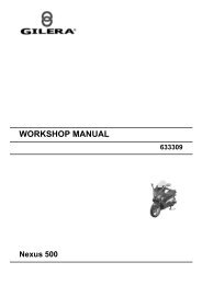


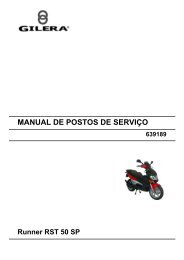
![Use the clutch holder [B] to prevent the](https://img.yumpu.com/11393415/1/184x260/use-the-clutch-holder-b-to-prevent-the.jpg?quality=85)