Prof. Livan Fratini
Prof. Livan Fratini
Prof. Livan Fratini

You also want an ePaper? Increase the reach of your titles
YUMPU automatically turns print PDFs into web optimized ePapers that Google loves.
<strong>Prof</strong>. <strong>Livan</strong> <strong>Fratini</strong>
SALDATURE<br />
GIUNZIONI – FASTENING MECCANICO
Alcuni tipi di saldature
CLASSIFICAZIONE SALDATURE<br />
AUTOGENE<br />
Per fusione<br />
(Gas, arco, laser)<br />
Per pressione / resistenza elettrica<br />
(Per punti punti, punti punti, , a a rulli rulli, rulli rulli, , per scintillio scintillio) scintillio scintillio)<br />
ETEROGENE<br />
Brasature
SALDATURE A GAS<br />
MIX Acetilene e Ossigeno<br />
• Economica<br />
• Indipendente<br />
Reazione primaria<br />
Reazione secondaria<br />
• Problemi di stoccaggio
SALDATURE A GAS<br />
Taglio ossiacetilenico
SALDATURA CON ELETTRODI RIVESTITI
SALDATURA CON ELETTRODI RIVESTITI<br />
La temperatura degli elettrodi: elettrodi si registrano mediamente temperature dell’ordine di 3500°K 3500<br />
all’anodo all anodo e di 2700 2700°K al catodo: catodo l’energia energia generata dal passaggio della corrente si distribuisce<br />
infatti in modo diseguale tra i due elettrodi ed in particolare un terzo di essa interessa il catodo e<br />
due terzi l’anodo anodo. La temperatura anodica è pertanto superiore a quella catodica; catodica nella terminologia<br />
tecnica si dice che il processo di saldatura avviene con polarità diretta quando il pezzo da<br />
saldare costituisce l’anodo anodo del circuito, con polarità inversa quando invece il pezzo è il<br />
catodo catodo.<br />
Il Il punto di di funzionamento è all’intersezione<br />
all intersezione tra tra la<br />
la<br />
caratteristica dell dell’arco arco e la caratteristica della saldatrice. saldatrice Il<br />
tratto di caratteristica utilizzato è quello di arco<br />
strozzato strozzato, in cui il funzionamento è stabile<br />
Il processo può avvenire sia in corrente continua che alternata. alternata La penetrazione della saldatura<br />
dipende dalla lunghezza dell dell’arco, arco, che, a parità di tensione di alimentazione, determina la corrente di<br />
saldatura, e, nel caso in cui si operi in corrente continua, dalla polarità prescelta prescelta.
SALDATURE TIG (TUNGSTEN INERT GAS)
SALDATURE TIG (TUNGSTEN INERT GAS)<br />
Generazione del calore, fenomeni ossidativi<br />
Materiale Corrente e polarità<br />
Accai dolci CC, polarità diretta<br />
Acciai inox CC, polarità diretta o CA<br />
Leghe di Alluminio CA<br />
Leghe di Magnesio CA<br />
Leghe di Nickel CC, polarità diretta<br />
Ottone CA<br />
Rame CC, polarità diretta
SALDATURE MIG/MAG – METAL INERT (ACTIVE) GAS
SALDATURE MIG/MAG – METAL INERT (ACTIVE) GAS<br />
Sensitività dell’arco dell arco elettrico (Autoregolazione)
SALDATURE AD ARCO SOMMERSO<br />
Tubi saldati
SALDATURE LASER<br />
Precisione e velocità
SALDATURE LASER
SALDATURE LASER
CARATTERISTICHE DELLE SALDATURE PER FUSIONE
SALDATURE A RESISTENZA<br />
Per punti
SALDATURE A RESISTENZA<br />
SALDATURE PER PUNTI - FUNZIONAMENTO
SALDATURE A RESISTENZA<br />
SALDATURE PER PUNTI - FUNZIONAMENTO<br />
Regolazione del processo
SALDATURE A RESISTENZA<br />
SALDATURE PER PUNTI - FUNZIONAMENTO<br />
Esecuzione del processo
SALDATURE A RESISTENZA<br />
SALDATURE A RULLI<br />
Schema
CICLO TERMICO DI SALDATURA<br />
Distorsioni<br />
Modifica struttura<br />
Cricche<br />
La ZTA
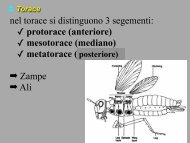
Clinching<br />
Clinching is a joining method in which sheet<br />
metal parts are deformed locally and<br />
connected without the use of additional<br />
elements. The material is formed between a<br />
punch and a die in such a way that<br />
mechanical interlocking of the sheets<br />
themselves occurs.<br />
Rapidity<br />
Cleanliness<br />
Low noise<br />
No heat
Clinching: process mechanics<br />
Four different stages are developed:<br />
positioning of the blanks between the punch and the die;<br />
plastic deformation of the blanks;<br />
fulfillment of the die cavity and inverse extrusion mechanics of the<br />
material;<br />
extraction of the the joint from the the dies.
Clinching: process mechanics<br />
Typical applications fields are<br />
the automotive (i.e. fuel tanks,<br />
heat shields, airbag case, etc) ,<br />
electromechanical (air shafts, air<br />
cleaners etc..)<br />
In this last years it has been<br />
appreciate by some car<br />
producers like Audi and Lotus.
Clinching: operating parameters<br />
Geometrical parameters<br />
Clinch shape<br />
Thicker blank in the upper position<br />
(2up config.)<br />
Thinner blank at the top (1up<br />
config.) would be cut and the joint<br />
could not be obtained<br />
Technological parameter<br />
Oil pressure<br />
[bar]<br />
220 2200<br />
240 2380<br />
260 2520<br />
280 2750<br />
300 2880<br />
Applied load<br />
[N]<br />
Blank-holder<br />
Punch<br />
Die
Clinching<br />
Clinching<br />
“Press Clinching”<br />
(cylindrical punch)<br />
“Shear Clinching”<br />
(punch with rectangular section)<br />
Rigid die<br />
“Rubber like” die
Clinching<br />
ADV<br />
BENEFICI DELLA TECNICA<br />
No degradation phenomena, neither post joining treatments nor pre-joining preparation<br />
treatments are needed.<br />
Good fatigue and corrosion resistance of the joints.<br />
Flexibility of the process (coated blanks, large thickness range, dissimilar joints and so on).<br />
Hybrid-joints (for instance with adhesives).<br />
Simple fixture and large die life (about 250000 joints).<br />
No gases.<br />
Non-destructive techniques can be easily applied.<br />
DIS-ADV<br />
“Two-sides” process<br />
Process engineering needed
Clinching
Clinching<br />
AA6082, Steel P01, thicknesses 1-2mm
Clinching
Clinching: the electro-hydraulic fixture
Clinching: the electro-hydraulic fixture<br />
A<br />
B
Clinching: FE analyses results<br />
Geometry prediction<br />
350atm<br />
600atm
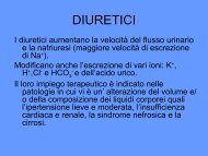
The self-piercing riveting process (SPR)<br />
A semi-tubular rivet is pressed by a punch into two<br />
(or more) sheets of material that are supported by a<br />
small die with a suitable geometry.<br />
Load (kN)<br />
30<br />
20<br />
10<br />
0<br />
clamping piercing<br />
p= 7 MPa<br />
p= 9 MPa<br />
p=15MPa<br />
flaring<br />
compression<br />
8 10 12 14 16<br />
displacement (mm)<br />
p= 29 MPa
The self-piercing riveting process (SPR)<br />
The self-pierce rivet is designed to both<br />
pierce and form a permanent fastening within<br />
the materials being joined. Having pierced the<br />
upper sheet of material, the rivet expands in<br />
the lower sheet, usually without cutting it, to<br />
form a mechanical interlock<br />
Rapidity<br />
Cleanliness<br />
Low noise<br />
No heat<br />
Large setting forces required<br />
Additional consumable items, and<br />
therefore weight the joint
The self-piercing riveting process (SPR)<br />
The engineering<br />
The rivet geometry and material have to be optimised, in conjunction with the appropriate<br />
die, for each application (materials to be joined, total thickness, functional requirements or<br />
aesthetic appeal, etc.)<br />
Traditionally, the process design procedure is based on the experience and involves trialand-error<br />
loops. This approach is highly time and cost expensive<br />
The activity<br />
To study the mechanisms of joint formation<br />
To study the mechanisms of joint failure under shear forces<br />
To study the capability of FE modeling when used in the design phase
SPR: the fixture<br />
Blankholder<br />
Punch<br />
Die<br />
Single effect hydraulic press<br />
(DT)<br />
Position<br />
transducer<br />
(PC)<br />
Pressure transducer<br />
(LC)<br />
Load cell
SPR: the tests<br />
Load [N]<br />
clamping<br />
Al 6082, 3 + 3 mm, rivet RC, die DB<br />
piercing<br />
Punch stroke [mm]<br />
expansion<br />
compression<br />
Pressure Pressure [bar]<br />
[bar]
SPR: the tests
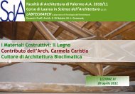
SALDATURE ALLO STATO SOLIDO<br />
FSW process was developed by the Welding<br />
Institute in 1991<br />
FSW is a solid state welding process in which a specially<br />
designed rotating pin is first inserted into the adjoining<br />
edges of the sheets to be welded with a proper nuting<br />
angle and then moved all along the joint<br />
Some of FSW process advantage are: are<br />
Absence of fusion with consequent absence of<br />
Porosity<br />
weld fumes, noise or sparks<br />
grain growth<br />
residual stress and distortion
SALDATURE ALLO STATO SOLIDO<br />
Geometrical parameters<br />
Height Height of pin<br />
Diameter Diameter and shape of pin<br />
Shoulder Shoulder surface<br />
Technological parameters<br />
Force Force superimposed on rotating tool<br />
Rotating Rotating speed<br />
Feed Feed rate<br />
Nuting Nuting angle<br />
Tool Tool sinking<br />
AA R<br />
V f
SALDATURE ALLO STATO SOLIDO<br />
Some of FSW process advantage are ( (cont’d cont’d): ):<br />
produces desirable microstructures in the weld and heat-<br />
affected zones (dynamic dynamic recristallization<br />
recristallization)<br />
Low energy consumption (compared compared to the conventional fusion<br />
welding welding)<br />
Absence of filler needed to be added and oxidation<br />
protection<br />
FSW can successfully join materials that are "unweldable unweldable" by<br />
fusion welding methods<br />
Frictional action heating<br />
Plastic deformation heating<br />
No melting<br />
Complex flow pattern<br />
Eclipse<br />
Eclipse<br />
Eclipse
SALDATURE ALLO STATO SOLIDO<br />
Courtesy of LFT Institute