marvin - Klima-Therm
marvin - Klima-Therm
marvin - Klima-Therm

Create successful ePaper yourself
Turn your PDF publications into a flip-book with our unique Google optimized e-Paper software.
2.2 Rotazione della batteria<br />
Se per esigenze di installazione fosse necessario ruotare la batteria,<br />
procedere nel seguente modo:<br />
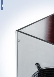
• Togliere il mantello di copertura del ventilconvettore (Fig. A).<br />
• Togliere il pannello di tamponamento 1 posto davanti alla batteria<br />
allentando le relative viti.<br />
• Sfilare la batteria 2 dall’unità ventilante dopo aver agito sui punti di<br />
fissaggio (Fig. B).<br />
• Togliere i pretranciati 3 dal fianco sx (Fig. C).<br />
• Inserire la batteria dopo averla ruotata ed infine fissarla.<br />
• Chiudere i fori degli attacchi idraulici rimasti inutilizzati sul fianco dx<br />
con della gomma adesiva 4 .<br />
• Spostare il supporto comandi e il relativo cablaggio sul fianco dx del<br />
ventilconvettore (Fig. D).<br />
• Spostare il collegamento di messa a terra 5 sul fianco dx.<br />
• Spostare la targhetta di tamponamento da sotto lo sportellino di dx<br />
a quello di sx.<br />
• Ad operazioni ultimate rimontare il mantello di copertura.<br />
Fig. A Fig. B Fig. C<br />
2.3 Collegamenti elettrici<br />
Prima di effettuare qualsiasi operazione sulla parte<br />
elettrica del ventilconvettore togliere l’alimentazione<br />
spegnendo l’interuttore generale. Ricordarsi<br />
sempre di collegare il filo di terra.<br />
Il collegamento a terra é obbligatorio per legge.<br />
L’installatore deve provvedere alla sua realizzazione<br />
utilizzando l’apposito morsetto contrassegnato<br />
dall’indicazione internazionale di messa a terra.<br />
I collegamenti elettrici devono essere effettuati<br />
come da Fig. E e Fig. F.<br />
2.4 Avviamento<br />
Sfiatare l’impianto dopo averlo riempito.<br />
Inoltre sfiatare il ventilconvettore per mezzo<br />
delle apposite valvoline e controllare il buon funzionamento<br />
del ventilconvettore.<br />
Attenzione!<br />
Il primo avviamento del ventilconvettore deve<br />
essere effettuato alla massima velocità,<br />
lasciando girare il ventilatore per circa 4/5<br />
ore. Ripetere l’operazione dopo una lunga<br />
inattività.<br />
2.5 Orientamento delle alette delle griglie<br />
• Sbloccare la griglia all’estrema dx estraendo i piolini<br />
1 (Fig. G);<br />
• Spostare tutte le griglie verso dx 2 e sganciarle<br />
dalla sede;<br />
• Orientarle nella posizione desiderata 3 ;<br />
• Inserirle nella sede e farle scorrere verso sx 4 ;<br />
• Bloccare l’ultima griglia di dx sfondando il pretranciato<br />
in corrispondenza del foro presente nel<br />
mantello o facendo corrispondere l’interspazio fra<br />
le ultime due alette con il foro presente nel mantello<br />
e reinserire i piolini 5 .<br />
4<br />
2<br />
Al comando a bordo macchina (versioni verticali)<br />
Built-in to control (vertical versions)<br />
Fig. E<br />
Fig. F<br />
Connettore<br />
Connector<br />
Al comando remoto (versioni orizzontali)<br />
Remote control (horizontal versions)<br />
Fig. G<br />
1<br />
5<br />
2.2 Coil rotation<br />
If installation requirements make it necessary to rotate the coil, proceed<br />
in the following manner:<br />
• Remov the cabinet from the fan coil unit (Fig. A).<br />
• Remove protection panel 1 located in front of the coil by loosening<br />
the relative screws.<br />
• Slide coil 2 out from the fan unit after acting on the fastening points<br />
(Fig. B).<br />
• Remove the pre-punched pieces 3 from the lf side (Fig. C).<br />
• Insert the coil after rotating it and then fasten it.<br />
• Close the holes of the water connections which are unused on the rh<br />
side with the included adhesive rubber 4 .<br />
• Move the control support with its wiring to the rh side of the fan coil<br />
unit (Fig. D).<br />
• Move earth connection 5 to the rh side.<br />
• Remove the closure template below the right door and place it below<br />
the left one.<br />
• When the operation is concluded re-install the cabinet.<br />
Connettore / Connector<br />
Fig. D<br />
2.3 Electrical connections<br />
Before carrying out any operations on the electrical<br />
part of the fan coil unit, disconnect the electrical<br />
mains power supply by turning off the main<br />
switch. Always remember to connect the earth<br />
wire. The earth connection is required by law.<br />
The installer must provide for its realization by using<br />
the appropriate terminal which is marked with the<br />
international symbol for earth connections.<br />
The electrical connections must be made as<br />
shown in the picture E and picture F.<br />
2.4 Start-up<br />
Bleed the system after having filled it.<br />
Also bleed the fan coil unit by means of the<br />
appropriate valves and check fan coil unit for<br />
proper operation.<br />
Attention!<br />
The first start-up of the fan coil unit must be<br />
made at maximum speed, letting the fan run<br />
for 4-5 hours. Repeat this operation after a<br />
long shutdown period.<br />
2.5 Grilles orienting<br />
• Free the extreme right grille lifting the pins 1<br />
(Fig. G);<br />
• Shift grilles to the right 2 and remove them;<br />
• Turn grilles as desired 3 ;<br />
• Insert grilles and shift them to the left 4 ;<br />
• Block the last grille on the right punching the<br />
precut hole of the cabinet or putting in correspondence<br />
the space between the last two<br />
finns with the hole and reinsert the pins 5 .<br />
3<br />
270°<br />
180°<br />
0°<br />
90°