Moltiplicatori di pressione
Moltiplicatori di pressione
Moltiplicatori di pressione

You also want an ePaper? Increase the reach of your titles
YUMPU automatically turns print PDFs into web optimized ePapers that Google loves.
2<br />
<strong>Moltiplicatori</strong> <strong>di</strong> <strong>pressione</strong> aria/olio<br />
<strong>Moltiplicatori</strong> <strong>di</strong> <strong>pressione</strong> olio/olio<br />
Pompe oleopneumatiche<br />
Air/Oil Pressure Multipliers<br />
Oil/Oil Pressure Multipliers<br />
Oil-pneumatic pumps<br />
Caratteristiche tecniche Modello 100 Technical specifications Model 100<br />
Camera pneumatica:<br />
Flange:<br />
Pistone:<br />
Stelo tuffante:<br />
Testata:<br />
Molla:<br />
Tiranti - da<strong>di</strong>:<br />
Guarnizioni<br />
fusione <strong>di</strong> alluminio<br />
alluminio ano<strong>di</strong>zzato argento<br />
(x tipo RP) pistone integrale NBR<br />
(x tipo RM) alluminio<br />
acciaio C53 temprato cromato duro 0,25<br />
micron<br />
acciaio brunito<br />
(solo tipo RM) acciaio C85<br />
acciaio zincato<br />
poliuretano NBR<br />
Pneumatic chamber:<br />
Flange:<br />
Piston:<br />
Piston rod:<br />
Cylinder head:<br />
Spring:<br />
Tie rods-nuts:<br />
Gaskets:<br />
Smelting made of aluminium<br />
ano<strong>di</strong>zed aluminium<br />
(type R.P.) NBR complete piston<br />
(type R.M.) aluminium<br />
hardened and cromated steel<br />
(C53)<br />
hardness 0,25 micron<br />
burnished steel<br />
(type R.M. only) steel C85<br />
galvanized steel<br />
polyurethane NBR<br />
Caratteristiche tecniche Modello 160-200 Technical specifications Model 160-200<br />
Camera pneumatica:<br />
Flange:<br />
Pistone:<br />
Stelo tuffante:<br />
Testata:<br />
Molla:<br />
Tiranti - da<strong>di</strong>:<br />
Guarnizioni:<br />
alluminio ano<strong>di</strong>zzato argento<br />
fusione <strong>di</strong> alluminio<br />
acciaio C53 temprato cromato duro 0,25<br />
micron<br />
acciaio brunito<br />
(solo tipo RM) acciaio C85<br />
acciaio zincato<br />
poliuretano NBR<br />
Norme d’ impiego:<br />
• Olio idraulico minerale ISO HM32.<br />
• Temperatura <strong>di</strong> esercizio –10°C +60°C.<br />
• Montaggio orizzontale o verticale con pompante rivolto verso<br />
l’alto (nel caso <strong>di</strong> posizione verticale fare attenzione a orientare il<br />
serbatoio).<br />
• Si consiglia <strong>di</strong> avere il serbatoio olio posizionato leggermente più<br />
in alto rispetto all’ utilizzo.<br />
• Usare gruppo filtro riduttore lubrificatore per l’aria.<br />
• In fase <strong>di</strong> scelta del moltiplicatore prevedere che il volume<br />
d’ olio erogato sia del 20% superiore alla necessità<br />
d’ utilizzo.<br />
• Per cicli veloci e ripetitivi si consiglia l’uso <strong>di</strong> moltiplicatore con<br />
ritorno pneumatico montando valvola scarico rapido.<br />
• Durante la prima fase <strong>di</strong> installazione procedere ad un accurato<br />
spurgo d’aria dell’ impianto oleo<strong>di</strong>namico.<br />
• Nei modelli RM (ritorno a molla) la <strong>pressione</strong> olio in uscita<br />
può variare da +0 a –25 bar.<br />
Pneumatic chamber:<br />
Flange:<br />
Piston:<br />
Piston rod:<br />
Cylinder head:<br />
Spring:<br />
Tie rods - nuts:<br />
Gaskets:<br />
Ano<strong>di</strong>zed aluminium<br />
Smelting made of aluminium<br />
Hardened and hard cromated steel<br />
C53 hardness 0,25 micron<br />
Burnished steel<br />
(type R.M. only) steel C85<br />
galvanized steel<br />
polyurethane NBR<br />
Instruction for use:<br />
• Hydraulic mineral oil ISO HM32.<br />
• Working temperature from –10°C to +60°C.<br />
• Horizontal or vertical assembly but the pumping must be<br />
oriented towards (for vertical position, the oil tank must be<br />
oriented with vertical axis).<br />
• The oil tank should be positioned upper than the cylinders.<br />
• For trouble-free operation, use the unit filter+ reducer<br />
+lubrificator.<br />
• When you are choosing pressure multiplier be careful that<br />
volume of oil available is 20% more than that your<br />
application needs.<br />
• For fast and repetitive working cycles, pressure multiplier<br />
pneumatic return with rapid <strong>di</strong>scharge valve is<br />
recommended.<br />
• When assembling for this time, accurately drain air from oilhydraulic<br />
circuit.<br />
• Output oil pressure can vary from +0 to –25 bar on<br />
spring return (RM) models.<br />
ENERFLUID si riserva la facoltà <strong>di</strong> variare modelli e ingombri senza preavviso – The above model and <strong>di</strong>mensions may be varied by ENERFLUID without prior notice<br />
SISTEMI E TECNOLOGIE PER: BLOCCAGGIO – ASSEMBLAGGIO – PRODUZIONE SYSTEMS AND TECHNOLOGY FOR: LOCKING – ASSEMBLY - PRODUCTION
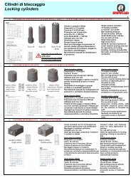
<strong>Moltiplicatori</strong> <strong>di</strong> Pressione Olio/Olio tipo 100<br />
Pressioni <strong>di</strong> esercizio 320 bar<br />
Oil/Oil pressure multipliers, type 100<br />
Working pressures 320 bar<br />
Disponibili in 5 modelli<br />
Con ritorno a molla (RM)<br />
Utilizzati solo con olio<br />
5 models available<br />
with spring return (RM)<br />
For use oil only<br />
R= Entrata olio R3/8<br />
Z= Uscite olio: n. 1 da R3/8 – n. 4 da R 1/4<br />
R= Oil inlet R 3/8<br />
Z= Oil outlets: n. 1 R 3/8 – n. 4 R 1/4<br />
DESCRIZIONE<br />
Azionamento a comando oleo<strong>di</strong>namico, ritorno a molla. Il funzionamento <strong>di</strong> questi organi<br />
pompanti è semplice: si tratta <strong>di</strong> un circuito idraulico chiuso a semplice effetto, collegato ad un<br />
serbatoio d’olio per il ripristino automatico, ad ogni corsa, <strong>di</strong> eventuali piccole per<strong>di</strong>te o<br />
trafilamenti. Il funzionamento avviene immettendo olio nel circuito dall’entrata R. Il ritorno è<br />
assicurato da una robusta molla. E’ possibile variare la <strong>pressione</strong> in uscita tramite regolazione<br />
della <strong>pressione</strong> dell’olio in entrata. Questi moltiplicatori possono essere montati in qualsiasi<br />
posizione avendo cura <strong>di</strong> sistemare il serbatoio <strong>di</strong> recupero in posizione verticale. Possono<br />
essere montati in sequenza ma in questo caso i serbatoi dovranno essere tolti e i fori tappati<br />
tranne uno.<br />
APPLICAZIONI<br />
Questi moltiplicatori vengono usati su macchine che <strong>di</strong>spongono <strong>di</strong> un impianto oleo<strong>di</strong>namico<br />
la cui <strong>pressione</strong> è insufficiente per il comando <strong>di</strong> sistemi <strong>di</strong> bloccaggio ad alta <strong>pressione</strong>.<br />
DESCRIPTION<br />
Hydraulic operation, spring return. These pumping devices are easy to operate. They consist<br />
of a single action hydraulic closed circuit connected to an oil tank with automatic topping up at<br />
each stroke to compensate small leakages or loss. The circuit is activated by pumping oil via<br />
the inlet R. A sturdy taper spring ensures return at max speed. The outgoing pressure can be<br />
varied by adjusting the incoming oil pressure. These multipliers can be mounted in any<br />
position, but the recovery tank must be placed upright. They can be mounted in series but the<br />
tank must be removed and all the holes, except one, plugged.<br />
APPLICATIONS<br />
These multipliers are used on machines with hydraulic systems, the pressure of which is not<br />
sufficient to control high pressure locking systems.<br />
DATI TECNICI E DIMENSIONI ● SPECIFICATIONS AND DIMENSIONS<br />
MODELLO<br />
MODEL<br />
100.70.1.2<br />
100.50.1.4<br />
100.45.1.5<br />
100.35.1.8<br />
100.32.1.10<br />
Rapporto <strong>di</strong><br />
<strong>pressione</strong><br />
Pressure ratio<br />
1:2<br />
1:4<br />
1:5<br />
1:8<br />
1:10<br />
Pressione massima<br />
in entrata bar<br />
Max inlet pressure in<br />
bar<br />
160<br />
80<br />
64<br />
40<br />
32<br />
Pressione massima<br />
in uscita bar<br />
Max outlet pressure<br />
in bar<br />
ENERFLUID si riserva la facoltà <strong>di</strong> variare modelli e ingombri senza preavviso – The above model and <strong>di</strong>mensions may be varied by ENERFLUID without prior notice<br />
Erogazione olio per corsa<br />
cm³<br />
Oil flow per stroke cm³<br />
SISTEMI E TECNOLOGIE PER: BLOCCAGGIO – ASSEMBLAGGIO – PRODUZIONE SYSTEMS AND TECHNOLOGY FOR: LOCKING – ASSEMBLY - PRODUCTION 7<br />
320<br />
230<br />
117<br />
95<br />
57<br />
48
<strong>Moltiplicatori</strong> <strong>di</strong> Pressione Aria/Olio tipo 200<br />
Pressioni <strong>di</strong> esercizio da 200 a 512 bar<br />
Air/Oil pressure multipliers, type 200<br />
Working pressures from 200 to 512 bar<br />
Disponibili in 20 modelli<br />
N. 10 con ritorno a molla (RM)<br />
N. 10 con ritorno pneumatico (RP)<br />
Pressione massima aria 8 bar<br />
Utilizzati solo con olio<br />
20 models available<br />
10 with spring return (RM)<br />
10 with pneumatic return (RP)<br />
Max air pressure 8 bar<br />
For use with oil only<br />
6<br />
R= Entrata aria R3/8<br />
Z= Uscite olio: n. 2 da R3/8 – n. 1 da R<br />
1/4<br />
R= Air inlet R 3/8<br />
Z= Oil outlets: n. 2 R 3/8 – n. 1 R 1/4<br />
DESCRIZIONE e APPLICAZIONI<br />
Il funzionamento <strong>di</strong> questi organi pompanti è semplice. Si tratta <strong>di</strong> un circuito idraulico chiuso a semplice<br />
effetto collegato ad un contenitore d’olio per il ripristino automatico, ad ogni corsa, <strong>di</strong> eventuali piccole<br />
per<strong>di</strong>te e trafilamenti. Il funzionamento avviene immettendo aria nel circuito pneumatico dall’entrata R. Il<br />
ritorno è assicurato da una robusta molla conica per il tipo RM o in<br />
doppio effetto,tipo RP, che consente la massima velocità <strong>di</strong> ritorno.<br />
La <strong>pressione</strong> dell’olio in uscita è variabile tramite la regolazione della <strong>pressione</strong> aria in entrata. Questi<br />
moltiplicatori possono essere montati in qualsiasi posizione avendo cura <strong>di</strong> sistemare il serbatoio <strong>di</strong><br />
recupero sempre nella posizione verticale. Per il buon funzionamento si consiglia l’uso <strong>di</strong> gruppi FRL (filtro,<br />
regolatore, lubrificatore) con portata minima NL/min. 300. Per una maggiore sicurezza si consiglia <strong>di</strong><br />
montare valvole <strong>di</strong> non ritorno a monte della valvola <strong>di</strong> comando.<br />
Volume olio serbatoio circa 140 cm³.<br />
Per l’azionamento <strong>di</strong> sistemi <strong>di</strong> bloccaggio per attrezzature su macchine utensili, morse,ecc.<br />
Inoltre sono ottimamente impiegati per il comando <strong>di</strong> stampi e moduli per rivettare, piegare, marcare,<br />
pressare, tranciare, punzonare, imbutire e ricalcare.<br />
DESCRIPTION and APPLICATIONS<br />
These pumping device are easy to operate. They consist of a single-action hydraulic closed circuit<br />
connected to an oil tank with automatic topping up to compensate small leakages or loss. The circuit is<br />
activated by pumping air into the pneumatic circuit via the inlet R.A sturdy taper spring for<br />
type RM or dual-action spring for type RP ensures return at max speed. Output oil pressure can be varied<br />
by adjusting the inlet air pressure. These multipliers can be mounted in any position, but the recovery tank<br />
must be placed upright.<br />
For trouble free operations, FRL units (filter, regulator, lubricator) with min flow of 300 NL/min. are<br />
recommended. As a further safety precaution, mount return valves before the control valve.<br />
For camping system on machine-tools, vices, etc. Also ideal for controlling <strong>di</strong>es and riveting, ben<strong>di</strong>ng,<br />
pressing, blanking, punching, drawing and upsetting modules.<br />
Tank volume about 140 cm³.<br />
DATI TECNICI E DIMENSIONI ● SPECIFICATIONS AND DIMENSIONS<br />
Rapporto <strong>di</strong> Pressione olio con aria a<br />
MODELLO<br />
MODEL<br />
<strong>pressione</strong><br />
Pressure ratio<br />
Oil pressure with air at<br />
8 bar 6 bar<br />
200.25.05.RM<br />
200.25.15.RM<br />
1:64 512 384<br />
200.28.05.RM<br />
200.28.15.RM 1:51 408 306<br />
200.32.05.RM<br />
200.32.15.RM<br />
200.35.05.RM<br />
200.35.15.RM<br />
200.40.05.RM<br />
200.40.15.RM<br />
200.25.05.RP<br />
200.25.15.RP<br />
200.28.05.RP<br />
200.28.15.RP<br />
200.32.05.RP<br />
200.32.15.RP<br />
200.35.05.RP<br />
200.35.15.RP<br />
200.40.05.RP<br />
200.40.15.RP<br />
1:39 312 234<br />
1:32 256 192<br />
1:25 200 150<br />
1:64 512 384<br />
1:51 408 306<br />
1:39 312 234<br />
1:32 256 192<br />
1:25 200 150<br />
Erogazione olio per<br />
Dimensioni<br />
Corsa cm³<br />
Dimensions<br />
Oil flow per stroke cm³ A I L<br />
ENERFLUID si riserva la facoltà <strong>di</strong> variare modelli e ingombri senza preavviso – The above model and <strong>di</strong>mensions may be varied by ENERFLUID without prior notice<br />
SISTEMI E TECNOLOGIE PER: BLOCCAGGIO – ASSEMBLAGGIO – PRODUZIONE SYSTEMS AND TECHNOLOGY FOR: LOCKING – ASSEMBLY - PRODUCTION<br />
28<br />
73<br />
36<br />
92<br />
47<br />
120<br />
56<br />
144<br />
74<br />
187<br />
20<br />
66<br />
25<br />
83<br />
33<br />
108<br />
39<br />
130<br />
51<br />
169<br />
200<br />
300<br />
200<br />
300<br />
200<br />
300<br />
200<br />
300<br />
200<br />
300<br />
200<br />
300<br />
200<br />
300<br />
200<br />
300<br />
200<br />
300<br />
200<br />
300<br />
185<br />
285<br />
185<br />
285<br />
185<br />
285<br />
185<br />
285<br />
185<br />
285<br />
185<br />
285<br />
185<br />
285<br />
185<br />
285<br />
185<br />
285<br />
185<br />
285<br />
280<br />
480<br />
280<br />
480<br />
280<br />
480<br />
280<br />
480<br />
280<br />
480<br />
280<br />
480<br />
280<br />
480<br />
280<br />
480<br />
280<br />
480<br />
280<br />
480
<strong>Moltiplicatori</strong> <strong>di</strong> Pressione Aria/Olio tipo 160<br />
Pressioni <strong>di</strong> esercizio da 168 a 325 bar<br />
Air/Oil pressure multipliers, type 160<br />
Working pressures from 168 to 325 bar<br />
Disponibili in 12 modelli<br />
N. 6 con ritorno a molla (RM)<br />
N. 6 con ritorno pneumatico (RP)<br />
Pressione massima aria 8 bar<br />
Utilizzati solo con olio<br />
12 models available<br />
6 with spring return (RM)<br />
6 with pneumatic return (RP)<br />
Max air pressure 8 bar<br />
For use with oil only<br />
R= Entrata aria R3/8<br />
Z= Uscite olio: n. 2 da R3/8 – n. 1 da R 1/4<br />
R= Air inlet R 3/8<br />
Z= Oil outlets: n. 2 R 3/8 – n. 1 R 1/4<br />
DESCRIZIONE e APPLICAZIONI<br />
Il funzionamento <strong>di</strong> questi organi pompanti è semplice.<br />
Si tratta <strong>di</strong> un circuito idraulico chiuso a semplice effetto collegato ad un contenitore d’olio per il ripristino<br />
automatico, ad ogni corsa, <strong>di</strong> eventuali piccole per<strong>di</strong>te e trafilamenti.<br />
Il funzionamento avviene immettendo aria nel circuito pneumatico dall’entrata R.<br />
Il ritorno è assicurato da una robusta molla conica per il tipo RM o in doppio effetto,per il tipo RP, che<br />
consente la massima velocità <strong>di</strong> ritorno.<br />
La <strong>pressione</strong> dell’olio in uscita è variabile tramite la regolazione della <strong>pressione</strong> aria in entrata.<br />
Questi moltiplicatori possono essere montati in qualsiasi posizione avendo cura <strong>di</strong> sistemare il serbatoio<br />
<strong>di</strong> recupero sempre nella posizione verticale.<br />
Per il buon funzionamento si consiglia l’uso <strong>di</strong> gruppi FRL (filtro, regolatore, lubrificatore) con portata<br />
minima NL/min. 300.<br />
Per una maggiore sicurezza si consiglia <strong>di</strong> montare valvole <strong>di</strong> non ritorno a monte della valvola <strong>di</strong><br />
comando.<br />
Volume olio serbatoio circa 140 cm³.<br />
Per l’azionamento <strong>di</strong> sistemi <strong>di</strong> bloccaggio per attrezzature su macchine utensili, morse,ecc.<br />
Inoltre sono ottimamente impiegati per il comando <strong>di</strong> stampi e moduli per rivettare, piegare, marcare,<br />
pressare, tranciare, punzonare, imbutire e ricalcare.<br />
DESCRIPTION and APPLICATIONS<br />
These pumping device are easy to operate.<br />
They consist of a single-action hydraulic closed circuit connected to an oil tank with automatic topping<br />
up to compensate for small leakages or loss.<br />
The circuit is activated by pumping air into the pneumatic circuit via the inlet R.<br />
A sturdy taper spring for type RM or dual-action spring for type RP ensures return at max speed.<br />
Output oil pressure can be varied by adjusting the inlet air pressure.<br />
These multipliers can be mounted in any position, but the recovery tank must be placed upright.<br />
For trouble free operations, FRL units (filter, regulator, lubricator) with min flow of 300 NL/min. are<br />
recommended. As a further safety precaution, mount no return valves before the check valve.<br />
For camping system on machine-tools, vices, etc. also ideal for controlling <strong>di</strong>es and riveting, ben<strong>di</strong>ng,<br />
marking, pressing, blanking, punching, drawing and upsetting modules.<br />
Tank volume about 140 cm³.<br />
DATI TECNICI E DIMENSIONI ● SPECIFICATIONS AND DIMENSIONS<br />
MODELLO<br />
MODEL<br />
160.25.05.RM<br />
160.25.15.RM<br />
160.32.05.RM<br />
160.32.15.RM<br />
160.35.05.RM<br />
160.35.15.RM<br />
160.25.05.RP<br />
160.25.15.RP<br />
160.32.05.RP<br />
160.32.15.RP<br />
160.35.05.RP<br />
160.35.15.RP<br />
Rapporto <strong>di</strong><br />
<strong>pressione</strong><br />
Pressure ratio<br />
Pressione olio con aria a<br />
Oil pressure with air at<br />
8 bar 6 bar<br />
1:41 328 246<br />
1:25 200 150<br />
1:21 168 126<br />
1:41 328 246<br />
1:25 200 150<br />
1:21 168 126<br />
Erogazione olio per<br />
Corsa cm³<br />
Oil flow per stroke cm³<br />
ENERFLUID si riserva la facoltà <strong>di</strong> variare modelli e ingombri senza preavviso – The above model and <strong>di</strong>mensions may be varied by ENERFLUID without prior notice<br />
A<br />
Dimensioni<br />
Dimensions<br />
I L<br />
SISTEMI E TECNOLOGIE PER: BLOCCAGGIO – ASSEMBLAGGIO – PRODUZIONE SYSTEMS AND TECHNOLOGY FOR: LOCKING – ASSEMBLY - PRODUCTION 5<br />
22<br />
71<br />
37<br />
117<br />
44<br />
140<br />
18<br />
67<br />
30<br />
110<br />
36<br />
132<br />
180<br />
280<br />
180<br />
280<br />
180<br />
280<br />
180<br />
280<br />
180<br />
280<br />
180<br />
280<br />
165<br />
265<br />
165<br />
265<br />
165<br />
265<br />
165<br />
265<br />
165<br />
265<br />
165<br />
265<br />
260<br />
460<br />
260<br />
460<br />
260<br />
460<br />
260<br />
460<br />
260<br />
460<br />
260<br />
460
<strong>Moltiplicatori</strong> <strong>di</strong> Pressione Aria/Olio tipo 100<br />
Pressioni <strong>di</strong> esercizio da 160 a 312 bar<br />
Air/Oil pressure multipliers, type 100<br />
Working pressures from 160 to 312 bar<br />
Disponibili in 16 modelli<br />
N. 4 con ritorno a molla (RM)<br />
N. 12 con ritorno pneumatico (RP)<br />
Pressione massima aria 8 bar<br />
Utilizzati solo con olio<br />
16 models available<br />
4 with spring return (RM)<br />
12 with pneumatic return (RP)<br />
Max air pressure 8 bar<br />
For use with oil only<br />
R = Entrata aria R 1/4<br />
Z = Uscite olio n. 2 da R 1/4<br />
R = Air inlet R 1/4<br />
Z = 2 R 1/4 oil outlets<br />
4<br />
DESCRIZIONE e APPLICAZIONI<br />
Il funzionamento <strong>di</strong> questi organi pompanti è semplice.<br />
Si tratta <strong>di</strong> un circuito idraulico chiuso a semplice effetto collegato ad un contenitore d’olio per il ripristino<br />
automatico, ad ogni corsa, <strong>di</strong> eventuali piccole per<strong>di</strong>te e trafilamenti.<br />
Il funzionamento avviene immettendo aria nel circuito pneumatico dall’entrata R.<br />
Il ritorno è assicurato da una robusta molla conica per il tipo RM o in doppio effetto,tipo RP, che<br />
consente la massima velocità <strong>di</strong> ritorno.<br />
La <strong>pressione</strong> dell’olio in uscita è variabile tramite la regolazione della <strong>pressione</strong> aria in entrata.<br />
Questi moltiplicatori possono essere montati in qualsiasi posizione avendo cura <strong>di</strong> sistemare il serbatoio<br />
<strong>di</strong> recupero sempre nella posizione verticale.<br />
Per il buon funzionamento si consiglia l’uso <strong>di</strong> gruppi FRL (filtro, regolatore, lubrificatore) con portata<br />
minima NL/min. 300.<br />
Per una maggiore sicurezza si consiglia <strong>di</strong> montare valvole <strong>di</strong> non ritorno a monte della valvola <strong>di</strong><br />
comando.<br />
Per l’azionamento <strong>di</strong> minicilindri o attrezzature che necessitano <strong>di</strong> piccole quantità d’olio ad alta<br />
<strong>pressione</strong> in modo istantaneo. Inoltre sono impiegati per il comando <strong>di</strong> moduli per rivettare.<br />
Volume serbatoio circa 30 cm³.<br />
DESCRIPTION and APPLICATIONS<br />
These pumping devices are easy to operate.<br />
They consist of a single-action hydraulic closed circuit connected to an oil tank with automatic topping<br />
up to compensate for small leakages or loss.<br />
The circuit is activated by pumping air into the pneumatic circuit via the inlet R.<br />
A sturdy taper for type RM or dual-action spring for type RP ensures return at max speed.<br />
Output oil pressure can be varied by adjusting the inlet air pressure.<br />
These multipliers can be mounted in any position, but the recovery tank must be placed upright.<br />
For trouble free operations, FRL units ( filter, regulator, lubricator) with min flow of 300 NL/min. are<br />
recommended. As a safety precaution, mount no return valves before the check valve.<br />
For mini-cylinders or equipment requiring sudden small quantities of oil at high pressure.<br />
Also used for controlling modules for riveting. Tank volume about 30cm³.<br />
DATI TECNICI E DIMENSIONI ● SPECIFICATIONS AND DIMENSIONS<br />
MODELLO<br />
MODEL<br />
100.16.05.RM/1<br />
100.18.05.RM/1<br />
100.20.05.RM/1<br />
100.22.05.RM/1<br />
100.16.05.RP/1<br />
100.16.10.RP/1<br />
100.16.15.RP/1<br />
100.18.05.RP/1<br />
100.18.10.RP/1<br />
100.18.15.RP/1<br />
100.20.05.RP/1<br />
100.20.10.RP/1<br />
100.20.15.RP/1<br />
100.22.05.RP/1<br />
100.22.10.RP/1<br />
100.22.15.RP/1<br />
Rapporto <strong>di</strong><br />
<strong>pressione</strong><br />
Pressure ratio<br />
1:39<br />
1:30<br />
1:25<br />
1:20<br />
Pressione olio con aria a<br />
Oil pressure with air at<br />
8 bar 6 bar<br />
Erogazione olio per<br />
Corsa cm³<br />
Oil flow per stroke cm³<br />
Dimensioni<br />
Dimensions<br />
A I L<br />
SISTEMI E TECNOLOGIE PER: BLOCCAGGIO – ASSEMBLAGGIO – PRODUZIONE SYSTEMS AND TECHNOLOGY FOR: LOCKING – ASSEMBLY – PRODUCTION<br />
312<br />
240<br />
200<br />
160<br />
234<br />
180<br />
150<br />
120<br />
1:39 312 234<br />
1:30 240 180<br />
1:25 200 150<br />
1:20 160 120<br />
ENERFLUID si riserva la facoltà <strong>di</strong> variare modelli e ingombri senza preavviso – The above model and <strong>di</strong>mensions may be varied by ENERFLUID without prior notice<br />
12<br />
15<br />
18<br />
22<br />
12<br />
20<br />
30<br />
15<br />
25<br />
38<br />
18<br />
32<br />
47<br />
22<br />
38<br />
57<br />
135<br />
135<br />
185<br />
235<br />
135<br />
185<br />
235<br />
135<br />
185<br />
235<br />
135<br />
185<br />
235<br />
122<br />
122<br />
172<br />
222<br />
122<br />
172<br />
222<br />
122<br />
172<br />
222<br />
122<br />
172<br />
222<br />
231<br />
231<br />
331<br />
431<br />
231<br />
331<br />
431<br />
231<br />
331<br />
431<br />
231<br />
331<br />
431
8<br />
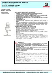
Pompe Oleopneumatiche Aria/Olio<br />
Pressioni <strong>di</strong> esercizio da 192 a 325 bar<br />
Air/Oil hydraulic pumps<br />
Working pressures from 192 to 325 bar<br />
Disponibili in 2 modelli<br />
Mandata in doppio effetto<br />
Pressione massima aria 8 bar<br />
2 models available<br />
Dual-action delivery<br />
Max air pressure 8 bar<br />
DESCRIZIONE E APPLICAZIONI<br />
Queste pompe sono dei moltiplicatori <strong>di</strong> <strong>pressione</strong> con mandata in doppio effetto in movimento<br />
alternativo. Funzionano con una normale linea d’aria da 3 a 8 bar consentono <strong>di</strong> ottenere portate e<br />
pressioni infinitamente variabili tramite la sola regolazione dell’aria in entrata. Quando la pompa ha<br />
raggiunto la <strong>pressione</strong> desiderata, cessa automaticamente <strong>di</strong> funzionare e si rimetterà in funzione<br />
automaticamente per compensare la caduta <strong>di</strong> <strong>pressione</strong> dovuta alla <strong>di</strong>minuzione <strong>di</strong> volume a causa <strong>di</strong><br />
eventuali per<strong>di</strong>te d’olio. Per il buon funzionamento si consiglia <strong>di</strong> montare un gruppo FRL (filtro,<br />
regolatore) con portata minima NL/min. 400.<br />
Serbatoio capacità lt. 2.<br />
Queste pompe trovano impiego nell’alimentazione <strong>di</strong> circuiti ad alta <strong>pressione</strong>. Le pompe pneumoidrauliche<br />
sono ideali per il comando <strong>di</strong>: cilindri a doppio effetto, a corsa breve, moduli o attrezzature con<br />
cilindri multipli a semplice effetto o piccole pressette per piegare, marcare, forare, laminare, tranciare,<br />
punzonare e ricalcare.<br />
DESCRIPTION AND APPLICATIONS<br />
These pumps are pressure multipliers with dual reciprocating action delivery. They operate with a<br />
standard 3-8 bar air supply and give infinitely variable flow rates and pressure merely by adjusting the<br />
incoming air. When the pump has reached the required pressure, it stops automatically and only restarts<br />
to compensate for any drop in pressure caused by reduced volume following oil leakage. For trouble free<br />
operations, FRL units (filter, regulator) with min. flow 400 NL/min. are recommended.<br />
Tank capacity in lt. 2.<br />
For supplying high pressure circuits. Hydraulic pumps are deal for short-stroke dual-action cylinder,<br />
modules or equipment with single-action multiple cylinders or small presses for ben<strong>di</strong>ng, marking,<br />
perforating, rolling, blanking punching and upsetting.<br />
A = Alim. max. 8 bar min. 3 bar<br />
Feed max 8 bar min. 3 bar<br />
R = Scarico olio<br />
Oil <strong>di</strong>scharge<br />
U = Uscita olio<br />
Oil outlet<br />
A = ¼ Gas<br />
R = ⅜ Gas<br />
U = ⅜ Gas<br />
aria filtrata e non lubrificata<br />
filtered and not lubricated air<br />
DATI TECNICI E DIMENSIONI ● SPECIFICATIONS AND DIMENSIONS<br />
MODELLO<br />
MODEL<br />
PMPO 160.24.36<br />
PMPO 160.40.22<br />
Rapporto <strong>di</strong><br />
<strong>pressione</strong><br />
Pressure ratio<br />
Erogazione olio per<br />
corsa cm³<br />
Oil flow per stroke cm³<br />
Erogazione olio a 6 bar<br />
Pressione olio con aria a<br />
NL/min.<br />
Oil pressure with air at<br />
Oil flow at 6 bar NL/min. 8 bar 6 bar<br />
SISTEMI E TECNOLOGIE PER: BLOCCAGGIO – ASSEMBLAGGIO – PRODUZIONE SYSTEMS AND TECHNOLOGY FOR: LOCKING – ASSEMBLY - PRODUCTION<br />
1:24<br />
1:40<br />
ENERFLUID si riserva la facoltà <strong>di</strong> variare modelli e ingombri senza preavviso – The above model and <strong>di</strong>mensions may be varied by ENERFLUID without prior notice<br />
36<br />
22<br />
3,25<br />
2,00<br />
192<br />
320<br />
144<br />
240
![GF series [PDF: 20.9MB]](https://img.yumpu.com/50118804/1/184x260/gf-series-pdf-209mb.jpg?quality=85)