Trave appoggiata a un estremo e incastrata all'altro, con carico ... - Sei
Trave appoggiata a un estremo e incastrata all'altro, con carico ... - Sei
Trave appoggiata a un estremo e incastrata all'altro, con carico ... - Sei

You also want an ePaper? Increase the reach of your titles
YUMPU automatically turns print PDFs into web optimized ePapers that Google loves.
12 Travi iperstatiche 12.1 Travi iperstatiche a <strong>un</strong>a campata<br />
12.1.3 <strong>Trave</strong> <strong>appoggiata</strong> a <strong>un</strong> <strong>estremo</strong> e <strong>incastrata</strong> all’altro, gravata di <strong>un</strong> <strong>carico</strong> <strong>con</strong>centrato<br />
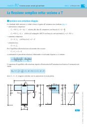
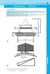
<strong>Trave</strong> <strong>appoggiata</strong> a <strong>un</strong> <strong>estremo</strong> e <strong>incastrata</strong> all’altro,<br />
<strong>con</strong> <strong>carico</strong> ripartito triangolare<br />
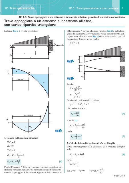
La trave [fig. a] è 1 volta iperstatica.<br />
T<br />
M<br />
V A<br />
1. Calcolo delle reazioni vincolari<br />
S P x = 0<br />
H B = 0<br />
x<br />
Y<br />
0 0<br />
0<br />
A<br />
y<br />
y = 0,447 ◊ l<br />
z = 0,775 ◊ l<br />
l<br />
M AB<br />
S Py = 0<br />
q ⋅ l<br />
RA + RB − =0<br />
2<br />
q ⋅ l<br />
RA + RB = [1]<br />
2<br />
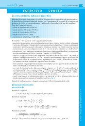
Poiché l’<strong>estremo</strong> A della trave non deve essere soggetto a traslazione<br />
verticale, nella trave a mensola che si ottiene sopprimendo<br />
l’appoggio A la somma algebrica della freccia di<br />
q x<br />
X<br />
Z<br />
B<br />
q<br />
V B<br />
M B<br />
M B<br />
0<br />
H B<br />
Fig. a<br />
x<br />
abbassamento f q dovuta al <strong>carico</strong> ripartito [fig. b] e della freccia<br />
di innalzamento f a provocata dal <strong>carico</strong> <strong>con</strong>centrato R A corrispondente<br />
alla reazione [fig. c] deve essere nulla, per cui<br />
l’equazione di <strong>con</strong>gruenza risulta:<br />
f q + f a = 0<br />
Fig. b<br />
Fig. c<br />
f q<br />
f a<br />
Poiché:<br />
fq =<br />
RA ⋅ l<br />
fa =<br />
3<br />
q ⋅ l<br />
3 ⋅ E ⋅ I<br />
4<br />
30 ⋅ E ⋅ I<br />
R A<br />
Sostituendo e riducendo si ottiene:<br />
q ⋅ l 4 − 10 ⋅ R A ⋅ l 3 = 0<br />
che risolta fornisce:<br />
q ⋅ l<br />
RA = [2]<br />
10<br />
e per la [1]:<br />
q ⋅ l<br />
RB = −<br />
2<br />
ossia:<br />
2<br />
RB = ⋅ q ⋅ l [3]<br />
5<br />
2. Calcolo della sollecitazione di sforzo di taglio<br />
Nella sezione generica X a distanza x da A lo sforzo di taglio<br />
vale:<br />
q<br />
VX = RA − x⋅ x<br />
[4]<br />
2<br />
dove:<br />
qx = q ⋅<br />
x<br />
l<br />
q ⋅ l<br />
10<br />
Per x = 0: V A s = 0 VA d = RA =<br />
q ⋅ l<br />
10<br />
q<br />
1<br />
© SEI - 2012
12 Travi iperstatiche 12.1 Travi iperstatiche a <strong>un</strong>a campata<br />
12.1.3 <strong>Trave</strong> <strong>appoggiata</strong> a <strong>un</strong> <strong>estremo</strong> e <strong>incastrata</strong> all’altro, gravata di <strong>un</strong> <strong>carico</strong> <strong>con</strong>centrato<br />
s q ⋅ l q ⋅ l 2<br />
Per x = l: VB = − =− ⋅q⋅l = RB<br />
10 2 5<br />
Uguagliando a zero l’equazione del taglio si ricava l’ascissa<br />
della sezione ove si ha V = 0:<br />
l<br />
y = ≈ 0,4472 ⋅ l<br />
5<br />
3. Calcolo della sollecitazione di momento flettente<br />
In <strong>un</strong>a sezione generica X il momento flettente è dato da:<br />
q<br />
MX = RA ⋅ x − ⋅ = ⋅ x − x⋅ x<br />
[5]<br />
Per x = 0: MA = 0<br />
3<br />
qx⋅ x x q ⋅ l<br />
2 3 10 6 ⋅ l<br />
Per x = :<br />
MAB = M + max = [6]<br />
Per x = l:<br />
MB = M − q ⋅ l<br />
max = − [7]<br />
2<br />
q ⋅ l<br />
15<br />
2<br />
l<br />
5<br />
15 ⋅ 5<br />
Uguagliando a zero la [5] si ricava la posizione della sezione<br />
Z di momento nullo, che fornisce il valore z ≈ 0,775 ⋅ l.<br />
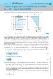
4. Calcolo della rotazione<br />
Si applica il principio di sovrapposizione degli effetti, sopprimendo<br />
l’incastro in B e sostituendolo <strong>con</strong> il momento d’incastro<br />
M B [fig. d], per cui la rotazione α in A è data dalla<br />
somma algebrica della rotazione α q dovuta al <strong>carico</strong> ripartito<br />
gravante sulla trave <strong>con</strong>siderata <strong>appoggiata</strong>, e dalla rotazione<br />
α m dovuta al momento M B agente in B sulla trave <strong>con</strong>siderata<br />
scarica, ossia:<br />
α = αq + αm ed essendo:<br />
q ⋅ l MB ⋅ l<br />
αq = ⋅ αm = = −<br />
6 ⋅ E ⋅ I<br />
3 7<br />
360 E ⋅ I<br />
q ⋅ l 3<br />
90 ⋅ E ⋅ I<br />
sostituendo e risolvendo si ottiene:<br />
q ⋅ l<br />
α = [8]<br />
3<br />
120 ⋅ E ⋅ I<br />
5. Calcolo della freccia in mezzeria<br />
Con le indicazioni della figura d risulta:<br />
f = fq + fm ed essendo:<br />
MB ⋅ l<br />
fq = ⋅ fm = = −<br />
2<br />
q ⋅ l<br />
16 ⋅ E ⋅ I<br />
4<br />
l<br />
2<br />
5<br />
768 E ⋅ I<br />
sostituendo si ottiene:<br />
q ⋅ l<br />
f = ⋅ [9]<br />
4 3<br />
1280 E ⋅ I<br />
l<br />
2<br />
Fig. d<br />
A<br />
A<br />
α<br />
f l 2<br />
f<br />
q ⋅ l 4<br />
240 ⋅ E ⋅ I<br />
A B<br />
αq fq αm fm A B<br />
B<br />
q<br />
q<br />
q<br />
B<br />
M B<br />
M B<br />
2<br />
© SEI - 2012