Micromotore da studio Studio micromotor - Carlo De Giorgi
Micromotore da studio Studio micromotor - Carlo De Giorgi
Micromotore da studio Studio micromotor - Carlo De Giorgi

You also want an ePaper? Increase the reach of your titles
YUMPU automatically turns print PDFs into web optimized ePapers that Google loves.
Manuale di Istruzione Uso e Manutenzione<br />
User and Maintenance manual<br />
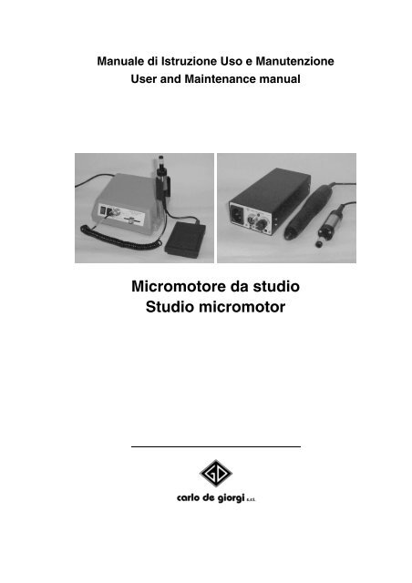
<strong>Micromotore</strong> <strong>da</strong> <strong>studio</strong><br />
<strong>Studio</strong> <strong>micromotor</strong>
'DWL PRGHOOR<br />
0RGHO GDWD<br />
7LSR 0RGHOOR $OLPHQWD]LRQH $QQR GL FRVWUX]LRQH<br />
7\SH 0RGHO 3RZHU VXSSO\
Manuale di Istruzione Uso e Manutenzione<br />
<strong>Micromotore</strong> <strong>da</strong> <strong>Studio</strong><br />
Via Tonale, 1 – 20021 Baranzate di Bollate (MI) – Italy<br />
Tel. +39.02.356.15.43 r.a. – Fax +39.02.356.18.08
MICROMOTORE DA STUDIO<br />
INDICE<br />
1 - NORME ED AVVERTENZE GENERALI.............................................. 5<br />
1.1 - PREMESSA....................................................................................... 5<br />
1.2 - DESCRIZIONE DELLA MACCHINA ................................................. 5<br />
1.3 - RIFERIMENTI NORMATIVI .............................................................. 5<br />
1.3.1 - Normativa obbligatoria.................................................................... 5<br />
1.3.2 - Normativa volontaria....................................................................... 5<br />
1.4 - PREDISPOSIZIONI A CARICO DEL CLIENTE ................................ 5<br />
1.5 - RICHIESTA INTERVENTI E RICAMBI ............................................. 5<br />
2 - CARATTERISTICHE TECNICHE ........................................................ 6<br />
2.1 - CARATTERISTICHE TECNICHE E PRESTAZIONI......................... 6<br />
3 - MICROMOTORI 551/00 - 553/00......................................................... 6<br />
3.1 - INSTALLAZIONE............................................................................... 6<br />
3.1.1 - PIAZZAMENTO .............................................................................. 6<br />
3.1.2 - ALLACCIAMENTO E MESSA IN SERVIZIO.................................. 6<br />
3.2 - FUNZIONAMENTO ED USO ............................................................ 7<br />
3.2.1 - FUNZIONAMENTO ........................................................................ 7<br />
3.2.2 - OPERATORE................................................................................. 7<br />
3.2.3 - AVVERTENZE DI SICUREZZA...................................................... 8<br />
3.3 - ISTRUZIONI PER L'OPERATORE ................................................... 8<br />
3.3.1 - COMANDI E UNITA' DI GOVERNO............................................... 8<br />
3.3.2 - INDICAZIONI RELATIVE ALL'USO ............................................... 9<br />
3.3.2.1 - Avviamento.................................................................................. 9<br />
3.3.2.2 - Modi di arresto ed arresto di emergenza..................................... 9<br />
3.3.2.3 - Avvertenze................................................................................... 9<br />
3.4 - MANUTENZIONE.............................................................................. 9<br />
3.4.1 PULIZIA ............................................................................................ 9<br />
3.5 - DIAGNOSTICA................................................................................ 10<br />
4 - MICROMOTORI 540/00 - 541/00....................................................... 11<br />
4.1 - INSTALLAZIONE............................................................................. 11<br />
4.1.1 - PIAZZAMENTO ............................................................................ 11<br />
4.1.2 - ALLACCIAMENTO E MESSA IN SERVIZIO................................ 11<br />
4.1.3 - CARICA DELL’ALIMENTATORE ................................................. 11<br />
I - 2 <strong>Carlo</strong> de <strong>Giorgi</strong>
MICROMOTORE DA STUDIO<br />
4.2 - FUNZIONAMENTO ED USO ...........................................................12<br />
4.2.1 - FUNZIONAMENTO.......................................................................12<br />
4.2.2 - OPERATORE................................................................................12<br />
4.2.3 - AVVERTENZE DI SICUREZZA ....................................................12<br />
4.3 - INDICAZIONI RELATIVE ALL'USO .................................................13<br />
4.3.1 - AVVIAMENTO (solo mod. 541/00)................................................13<br />
4.3.2 - ARRESTO DI EMERGENZA.........................................................13<br />
4.3.3 - AVVERTENZE ..............................................................................13<br />
4.4 - MANUTENZIONE.............................................................................13<br />
4.4.1 - PULIZIA E LUBRIFICAZIONE.......................................................13<br />
4.4.1.1 - Apparecchio mod. 540/00 ..........................................................13<br />
4.4.1.2 - Apparecchio mod. 541/00 ..........................................................13<br />
4.4.2 - MANUTENZIONE STRAORDINARIA (solo mod. 541/00)............14<br />
4.4.2.1 - La pinzetta non si apre ...............................................................14<br />
4.4.2.2 - Sostituzione del manipolo ..........................................................15<br />
4.4.2.3 - Sostituzione del motore..............................................................15<br />
5 - DIAGNOSTICA GENERALE...............................................................16<br />
<strong>Carlo</strong> de <strong>Giorgi</strong> I - 3
MICROMOTORE DA STUDIO<br />
DICHIARAZIONE CE DI CONFORMITA’<br />
La sottoscritta:<br />
CARLO DE GIORGI S.r.l.<br />
Via Tonale, 1<br />
20021 BARANZATE DI BOLLATE (MI) - I<br />
dichiara sotto la propria responsabilità che l’apparecchio:<br />
Tipo: MICROMOTORE DA STUDIO<br />
descritto in appresso:<br />
<strong>micromotor</strong>e destinato alla sgrossatura, levigatura e rifinitura di<br />
materiali utilizzati in laboratori odontotecnici,<br />
è conforme alle Disposizioni Legislative che traspongono la<br />
Direttiva Macchine 98/37/CEE e successivi emen<strong>da</strong>menti, la<br />
Direttiva Bassa Tensione 73/23/CEE e successivi emen<strong>da</strong>menti,<br />
e la Direttiva Compatibilità Elettromagnetica 89/336/CEE.<br />
Nome: <strong>De</strong> <strong>Giorgi</strong> Ariberto<br />
Amministratore delegato<br />
I - 4 <strong>Carlo</strong> de <strong>Giorgi</strong>
MICROMOTORE DA STUDIO<br />
1 - NORME ED AVVERTENZE GENERALI<br />
1.1 - PREMESSA<br />
Il presente manuale è proprietà della CARLO DE GIORGI S.r.l. Viene<br />
vietata la riproduzione o la cessione a terzi dei contenuti del presente<br />
documento. Tutti i diritti sono riservati.<br />
1.2 - DESCRIZIONE DELLA MACCHINA<br />
L’apparecchio in questione è un <strong>micromotor</strong>e destinato alla sgrossatura,<br />
levigatura e rifinitura di materiali utilizzati in laboratori odontotecnici.<br />
1.3 - RIFERIMENTI NORMATIVI<br />
1.3.1. - Normativa obbligatoria<br />
- Direttiva CEE n.98/37/CE - Direttiva Macchine - (D.P.R. n° 459/1996)<br />
- Direttiva CEE n.73/23 - Bassa Tensione (DBT) (Legge n° 791/1977, D.Lgs n°<br />
626/1996, D.Lgs n° 277/97)<br />
- Direttiva CEE n.89/336 relativa alla Compatibilitá Elettromagnetica (EMC) - (D.<br />
Lgs. n° 615/1996)<br />
- DPR 27.4.1955 n.547, "Norme per la prevenzione degli infortuni sul lavoro"<br />
- DPR 27.4.1956 n.303, "Norme generali per l'igiene del lavoro"<br />
- D.Lgs. 12.8.1991 n.277 di attuazione delle direttive CEE n.80/605; n.83/477;<br />
86/188; 88/642 in materia di protezione dei lavoratori contro i rischi derivanti <strong>da</strong><br />
esposizione ad agenti chimici, fisici e biologici durante il lavoro.<br />
1.3.2 - Normativa volontaria<br />
- EN 292 (1992) Sicurezza del macchinario - Concetti fon<strong>da</strong>mentali; principi<br />
generali di progettazione - Parte 1a - Terminologia metodologia di base (EN<br />
292-1) /Parte 2a - Specifiche e principi tecnici (EN 292-2).<br />
- EN 60204-1 Sicurezza del macchinario - Equipaggiamento elettrico delle<br />
macchine - Parte 1: Requisiti generali<br />
1.4 - PREDISPOSIZIONI A CARICO DEL CLIENTE<br />
L'utilizzatore installa il <strong>micromotor</strong>e per <strong>studio</strong> in locali adeguati dotati di<br />
impianto elettrico rispondente alla normativa vigente.<br />
Si raccoman<strong>da</strong> l’installazione dell’apparecchio in ambienti asciutti e<br />
illuminati in conformità alla legislazione vigente.<br />
NOTA: Con legislazione/normativa vigente si intende il quadro legislativo in vigore nel<br />
paese di utilizzazione.<br />
1.5 - RICHIESTA INTERVENTI E RICAMBI<br />
Per qualsiasi operazione di manutenzione elettrica, contattare la CARLO<br />
DE GIORGI di Baranzate di Bollate, Via Tonale, 1.<br />
<strong>Carlo</strong> de <strong>Giorgi</strong> I - 5
2 - CARATTERISTICHE TECNICHE<br />
2.1 - CARATTERISTICHE TECNICHE E PRESTAZIONI<br />
Prestazioni: durata ciclo di lavoro variabile<br />
MICROMOTORE DA STUDIO<br />
551/00 553/00 540/00 541/00<br />
Tensione V 230/120 100 ÷ 260 (*) (*) voltaggio per<br />
Frequenza Hz 50/60 50/60 ricarica<br />
Potenza installata W 100 12 Wh<br />
Vout su motorino V 30 24<br />
Vel. rotazione utensile max Giri/1’ 30.000 25.000 App. di classe<br />
II<br />
Fusibile ritar<strong>da</strong>to T A 1,25 ------<br />
Massa dell’apparecchio Kg 3,3 1<br />
3 - MICROMOTORI 551/00 - 553/00<br />
3.1 - INSTALLAZIONE<br />
3.1.1 - PIAZZAMENTO<br />
La macchina viene fornita già montata e pronta per il funzionamento,<br />
previo il collegamento all’alimentatore dei dispositivi di comando e del<br />
<strong>micromotor</strong>e completo di manipolo. Nell'imballaggio sono collocati:<br />
a) l’alimentatore, comprensivo di cavo di alimentazione;<br />
b) il <strong>micromotor</strong>e completo di innesto tipo Intra;<br />
c) il pe<strong>da</strong>le;<br />
d) supporto per <strong>micromotor</strong>e (solo per modello <strong>da</strong> tavolo);<br />
e) basetta in gomma (solo per modello <strong>da</strong> terra);<br />
f) istruzioni per l'uso.<br />
Per propria natura l’apparecchio può essere movimentato a mano senza<br />
la necessità di dispositivi di sollevamento.<br />
3.1.2 - ALLACCIAMENTO E MESSA IN SERVIZIO<br />
Facendo riferimento alla Figura 1 per il modello <strong>da</strong> tavolo e alla Figura 2<br />
per quello <strong>da</strong> terra, una volta posizionato l’apparecchio e dopo essersi<br />
assicurati di aver posto in OFF l'interruttore generale (1), si dovranno<br />
connettere, dopo aver inserito nella boccola laterale destra (8) il supporto<br />
del <strong>micromotor</strong>e:<br />
I - 6 <strong>Carlo</strong> de <strong>Giorgi</strong>
MICROMOTORE DA STUDIO<br />
- il pe<strong>da</strong>le (2) al connettore (3) posto sul retro dell’apparecchio (solo<br />
modello <strong>da</strong> tavolo);<br />
- il <strong>micromotor</strong>e (4) al connettore (5) posto sul fronte dell’apparecchio<br />
(sul retro per il modello <strong>da</strong> terra - vedi Fig. 2), innestando lo spinotto e<br />
quindi ruotando la ghiera senza forzare;<br />
- il cavo di alimentazione, inserendo la spina nella presa di<br />
alimentazione dell’impianto fisso, dotata di protezione contro le<br />
sovracorrenti.<br />
1<br />
6 10 5 7<br />
Fig. 1 (modello <strong>da</strong> tavolo)<br />
SI RICORDA DI NON METTERE MAI IN FUNZIONE L’APPARECCHIO SENZA PRIMA<br />
AVER CONNESSO PEDALE E MANIPOLO, E DI DISCONNETTERE QUESTI SOLO AD<br />
APPARECCHIO ISOLATO ELETTRICAMENTE.<br />
3.2 - FUNZIONAMENTO ED USO<br />
4<br />
8<br />
3.2.1 - FUNZIONAMENTO<br />
L’apparecchio deve essere posto su di un tavolo antistante all'operatore<br />
nel modello <strong>da</strong> tavolo; nel modello <strong>da</strong> terra si dovrà garantire che durante<br />
l’uso questo non si sposti a causa della pressione esercitata <strong>da</strong>l piede,<br />
per esempio ponendolo a fianco di una colonna.<br />
L’apparecchio va verificato (rotazione del motorino) ponendo in stato ON<br />
l’interruttore generale (1) e premendo il pe<strong>da</strong>le (2) (o agendo sulla leva (9)<br />
nei modelli <strong>da</strong> terra). In caso di malfunzionamento ricontrollare il<br />
collegamento dei connettori dopo aver posto in OFF l’interruttore generale<br />
e isolato elettricamente l’apparecchio.<br />
Dopo ogni utilizzo, l'apparecchio va posto in stato OFF.<br />
3.2.2 - OPERATORE<br />
L'operatore avvia l’apparecchio con un’azione volontaria (pe<strong>da</strong>le o leva a<br />
terra), per cui ha sempre il diretto controllo del suo funzionamento.<br />
<strong>Carlo</strong> de <strong>Giorgi</strong> I - 7<br />
2<br />
3<br />
11
MICROMOTORE DA STUDIO<br />
3.2.3 - AVVERTENZE DI SICUREZZA<br />
- L'uso dell’apparecchio deve essere effettuato <strong>da</strong> personale qualificato<br />
e comunque informato sui pericoli esistenti.<br />
- Indossare indumenti <strong>da</strong> lavoro idonei e osservare le norme di<br />
sicurezza valide per il proprio posto di lavoro.<br />
- Usare sempre mezzi di protezione individuale (occhiali, guanti,<br />
mascherine, ecc.).<br />
- Non utilizzare l’apparecchio senza aver prima collegato il pe<strong>da</strong>le (2) al<br />
connettore (3) posizionato sul retro dell’apparecchio (solo modello <strong>da</strong><br />
tavolo).<br />
- Non utilizzare l'apparecchio nelle vicinanze di materiali infiammabili;<br />
- Non aprire o smontare l’apparecchio.<br />
- Controllare periodicamente gli accessori, con particolare riferimento<br />
allo stato di isolamento dei cavi.<br />
3.3 - ISTRUZIONI PER L'OPERATORE<br />
3.3.1 - COMANDI E UNITA' DI GOVERNO<br />
Il <strong>micromotor</strong>e <strong>da</strong> <strong>studio</strong> è provvisto dei seguenti dispositivi di comando e<br />
di controllo posti sull’unità alimentatore (vedi Fig. 1 e 2):<br />
a) interruttore generale luminoso verde (1);<br />
b) selettore nero direzione rotazione utensile (reverse) (6). Quando si<br />
inverte il senso di rotazione (normale=orario, reverse=antiorario) si<br />
accende l’indicatore luminoso a diodo led arancio (10);<br />
c) pe<strong>da</strong>le di comando rotazione utensile (2) (solo modello <strong>da</strong> tavolo);<br />
d) regolatore a slitta di velocità di rotazione dell’utensile (7) (solo modello<br />
<strong>da</strong> tavolo);<br />
e) regolatore di velocità a pe<strong>da</strong>le (9) (solo modello <strong>da</strong> terra);<br />
f) fusibile di protezione del circuito di alimentazione (11).<br />
1<br />
6<br />
10<br />
9<br />
5 11<br />
Fig. 2 (modello <strong>da</strong> terra)<br />
I - 8 <strong>Carlo</strong> de <strong>Giorgi</strong>
MICROMOTORE DA STUDIO<br />
3.3.2 - INDICAZIONI RELATIVE ALL'USO<br />
3.3.2.1 - Avviamento<br />
La prima operazione <strong>da</strong> effettuare, per sicurezza a macchina isolata<br />
elettricamente, è l’inserimento dell’utensile con il quale si intende lavorare<br />
nel manipolo.<br />
L’apparecchio ora può essere alimentato agendo sull’interruttore generale<br />
(1). Azionando il pe<strong>da</strong>le (2) nel modello <strong>da</strong> tavolo (regolatore a pe<strong>da</strong>le (9)<br />
nella versione <strong>da</strong> terra) viene messo in moto il motorino.<br />
Agendo sul selettore reverse (6) si può invertire il senso di rotazione<br />
dell’utensile, segnalato <strong>da</strong>ll’accensione del led di colore arancio (10).<br />
Con il regolatore a slitta (7) nel modello <strong>da</strong> tavolo, o con il regolatore a<br />
pe<strong>da</strong>le (9) in quello <strong>da</strong> terra, è possibile variare la velocità di rotazione<br />
dell’utensile.<br />
3.3.2.2 - Modi di arresto ed arresto di emergenza<br />
La funzione di arresto può essere ottenuta:<br />
- rilasciando il pe<strong>da</strong>le (2) (o regolatore (9) modello <strong>da</strong> terra) di comando;<br />
- agendo sull’interruttore generale (1) ponendolo in OFF;<br />
- staccando il cavo di alimentazione <strong>da</strong>lla presa a cui è stata connessa.<br />
3.3.2.3 - Avvertenze<br />
In funzione dei materiali lavorati, è necessario adottare durante l’uso DPI<br />
(mascherine, guanti, occhiali, ecc.), e se necessario un sistema di<br />
aspirazione adeguato.<br />
3.4 - MANUTENZIONE<br />
Eventuali operazioni sulla parte elettrica all'interno dell’involucro devono<br />
essere eseguite <strong>da</strong> personale autorizzato ed istruito. Si segnala la<br />
presenza di tensione non innocua durante operazioni di manutenzione<br />
sull'apparato elettrico se eseguiti sotto tensione.<br />
3.4.1 - PULIZIA<br />
L’apparecchio non richiede particolari interventi manutentivi; per eseguire<br />
interventi di pulizia isolare sempre la macchina sezionando la fonte di<br />
energia.<br />
Particolare attenzione deve essere posta nei riguardi della pulizia del<br />
<strong>micromotor</strong>e completo di cavo (non a<strong>da</strong>tto per la sterilizzazione in<br />
autoclave) e del supporto, che possono essere puliti con alcool o con<br />
liquidi di sterilizzazione. La sterilizzazione del <strong>micromotor</strong>e non deve mai<br />
essere effettuata con liquidi conduttori di elettricità.<br />
<strong>Carlo</strong> de <strong>Giorgi</strong> I - 9
3.5 - DIAGNOSTICA<br />
MICROMOTORE DA STUDIO<br />
Nel caso di mancato funzionamento dell’apparecchio verificare il fusibile<br />
presente nella parte posteriore.<br />
Per la sostituzione utilizzare fusibili come <strong>da</strong> § 2.1 (<strong>da</strong>ti tecnici).<br />
Prima di verificare il fusibile porre l'interruttore generale in OFF e isolare<br />
la macchina <strong>da</strong>lla alimentazione di energia; verificare il funzionamento del<br />
fusibile e procedere quindi alla sostituzione. Richiuso il tappo a vite è<br />
possibile connettere nuovamente il cavo di alimentazione.<br />
I - 10 <strong>Carlo</strong> de <strong>Giorgi</strong>
MICROMOTORE DA STUDIO<br />
4 - MICROMOTORI 540/00 - 541/00<br />
4.1 - INSTALLAZIONE<br />
4.1.1 - PIAZZAMENTO<br />
L’apparecchio viene fornito già pronto per il funzionamento, previo il<br />
collegamento all’alimentatore del <strong>micromotor</strong>e completo di manipolo.<br />
Nell'imballaggio sono collocati:<br />
a) l’alimentatore a batteria e cavo di alimentazione per la carica;<br />
b) il <strong>micromotor</strong>e completo di innesto tipo Intra (solo modello 540/00);<br />
c) il <strong>micromotor</strong>e completo di manipolo, fornito di pinzetta ∅ 2,35 mm<br />
(solo modello 541/00);<br />
d) basetta in gomma;<br />
e) istruzioni per l'uso.<br />
6 2 3 4<br />
5<br />
Fig. 3<br />
4.1.2 - ALLACCIAMENTO E MESSA IN SERVIZIO<br />
Una volta posizionato l’apparecchio e dopo aver posto in OFF l'interruttore<br />
generale (1 - Fig. 3), si dovrà connettere il <strong>micromotor</strong>e al connettore<br />
(2) innestando lo spinotto e quindi ruotando la ghiera senza forzare.<br />
4.1.3 - CARICA DELL’ALIMENTATORE<br />
il cavo di alimentazione in dotazione (<strong>da</strong> collegare alla presa (6)) deve<br />
essere usato per la ricarica del pacco batterie. La tensione di<br />
alimentazione può variare <strong>da</strong> un minimo di 100 ad un massimo di 260V; i<br />
diversi valori di tensione accettati determinano differenti tempi di carica,<br />
compresi tra 24 e 48 ore circa.<br />
La prima volta che si effettua la carica si consiglia un tempo di almeno 48<br />
ore di carica. Per le volte successive non meno di 24 ore.<br />
<strong>Carlo</strong> de <strong>Giorgi</strong> I - 11<br />
1
MICROMOTORE DA STUDIO<br />
Durante la carica si consiglia di non usare il <strong>micromotor</strong>e (accertarsi che<br />
l’interruttore (1) sia in OFF.<br />
Per evitare che le batterie si possano <strong>da</strong>nneggiare è importante non<br />
scaricarle mai completamente. Se l’apparecchio non viene utilizzato per<br />
un periodo superiore ai due mesi sarà necessario ricaricarlo.<br />
4.2 - FUNZIONAMENTO ED USO<br />
4.2.1 - FUNZIONAMENTO<br />
L’apparecchio deve essere posizionato su di un tavolo antistante<br />
all'operatore. Il funzionamento dell’apparecchio va verificato ponendo in<br />
stato ON l’interruttore generale (1), con accensione del led verde (3), e<br />
successivamente ruotando il potenziometro (4); in questo modo il<br />
motorino deve incominciare a ruotare.<br />
E’ possibile invertire il senso di rotazione dell’utensile agendo sul selettore (5),<br />
solamente a motore fermo, o comunque quando il motore è al minimo dei giri.<br />
In caso di malfunzionamento ricontrollare il collegamento dei connettori<br />
dopo aver posto in OFF l’interruttore generale.<br />
Si ricor<strong>da</strong> che, dopo ogni uso, l'apparecchio va posto in stato OFF.<br />
4.2.2 - OPERATORE<br />
L'operatore avvia l’apparecchio con un’azione volontaria, per cui ha<br />
sempre il diretto controllo del suo funzionamento.<br />
4.2.3 - AVVERTENZE DI SICUREZZA<br />
- Vedere § 3.2.3 per le avvertenze generiche.<br />
- Non introdurre olio nel manipolo <strong>da</strong>l lato pinzetta (particolare B visibile<br />
in fig. 4 - solo modello 541/00).<br />
- Verificare sempre la corrispondenza tra il diametro degli utensili<br />
utilizzati e la pinzetta (solo modello 541/00).<br />
- non aprire per nessun motivo l’alimentatore a batterie quando è<br />
collegato per la fase di ricarica.<br />
I - 12 <strong>Carlo</strong> de <strong>Giorgi</strong>
MICROMOTORE DA STUDIO<br />
4.3 - INDICAZIONI RELATIVE ALL'USO<br />
4.3.1 - AVVIAMENTO (solo mod. 541/00)<br />
La prima operazione <strong>da</strong> effettuare, per sicurezza a motorino isolato<br />
elettricamente, è l’inserimento dell’utensile. Questo avviene <strong>da</strong>pprima<br />
girando la levetta (A - Fig. 4) di 90° indifferentemente a destra o a sinistra,<br />
inserendo l’utensile nella pinzetta di chiusura (B). Riportare infine la<br />
levetta (A) nella posizione di origine per serrare l’utensile.<br />
L’apparecchio a questo punto può essere alimentato agendo<br />
sull’interruttore generale (1) e si possono seguire le indicazioni del §<br />
4.2.1.<br />
D A C<br />
B<br />
E<br />
13 14<br />
Fig. 4<br />
4.3.2 - ARRESTO DI EMERGENZA<br />
La funzione di arresto può essere ottenuta agendo sull’interruttore<br />
generale (1) ponendolo nello stato OFF.<br />
4.3.3 - AVVERTENZE<br />
In funzione dei materiali lavorati, è necessario adottare durante l’uso DPI<br />
(mascherine, guanti, occhiali, ecc.).<br />
4.4 - MANUTENZIONE<br />
4.4.1 - PULIZIA E LUBRIFICAZIONE<br />
4.4.1.1 - Apparecchio mod. 540/00<br />
Vedere § 3.4.1.<br />
4.4.1.2 - Apparecchio mod. 541/00<br />
L’apparecchio richiede i seguenti interventi manutentivi, soprattutto se<br />
l’uso è continuativo (tutti i giorni): per operare interventi di pulizia isolare<br />
sempre il <strong>micromotor</strong>e <strong>da</strong>lla fonte di energia.<br />
<strong>Carlo</strong> de <strong>Giorgi</strong> I - 13
MICROMOTORE DA STUDIO<br />
- Pulire la testina (E), come visibile in Fig. 5.<br />
- Soffiare aria compressa attraverso la pinzetta nel punto (B - Fig. 4)<br />
preferibilmente con la pinzetta aperta (cioè ruotando di 90° la levetta A).<br />
- Lubrificare una volta al mese il manipolo, togliendo esclusivamente la<br />
vite (D) e facendo cadere una goccia d’olio nel foro filettato. Non<br />
introdurre assolutamente olio attraverso la pinzetta (punto - Fig. 4).<br />
E<br />
F<br />
Fig. 5<br />
4.4.2 - MANUTENZIONE STRAORDINARIA (solo mod. 541/00)<br />
4.4.2.1 - La pinzetta non si apre<br />
Facendo riferimento alla Fig. 4, Se la pinzetta di chiusura (B) non si apre<br />
dopo che la levetta (A) è stata ruotata di 90°, o se l’utensile non risulta<br />
serrato sufficientemente, è una regolazione, con la seguente procedura:<br />
- girare la levetta (A) di 90° in modo che la pinzetta esca al massimo<br />
possibile dell’estensione;<br />
- bloccare l’albero (C) del manipolo con un utensile piatto (2 mm);<br />
- inserire un cacciavite nella pinzetta (B), bloccata sul fondo dell’albero<br />
(C) mediante una vite;<br />
- allentare tale vite di mezzo giro girando il cacciavite in senso<br />
antiorario. Con tale operazione viene sbloccata la pinzetta (B);<br />
- se è necessario aumentare (diminuire) la forza di serraggio della<br />
pinzetta, girare questa con le dita in senso orario (antiorario);<br />
- sempre con l’apposito cacciavite bloccare la vite che ferma la pinzetta;<br />
- rilasciare l’utensile per sbloccare l’albero.<br />
I - 14 <strong>Carlo</strong> de <strong>Giorgi</strong>
MICROMOTORE DA STUDIO<br />
4.4.2.2 - Sostituzione del manipolo<br />
Quando si sostituisce il manipolo (13) avvitandolo sul <strong>micromotor</strong>e (14),<br />
abbiate cura che le alette di innesto dell’albero (C - Fig. 4) del manipolo<br />
entrino nelle loro sedi senza forzare, altrimenti si potrebbe rompere o<br />
rovinare il giunto sul motore (15 - Fig. 6).<br />
Non appena si avvertisse una forzatura, svitate subito il manipolo (14)<br />
riavvitandolo delicatamente, provando fino a trovare la giusta posizione.<br />
4.4.2.3 - Sostituzione del motore<br />
Dopo un determinato numero di ore (quantificabile in circa 2000 ore)<br />
potrebbe essere necessario cambiare il motorino interno del <strong>micromotor</strong>e<br />
a causa del decadimento delle sue caratteristiche.<br />
Per fare ciò seguire le seguenti istruzioni:<br />
- svitare il tappo posteriore (G - Fig. 6), lasciando libero il cavo elettrico,<br />
onde evitare attorcigliamenti all’atto dell’apertura/chiusura del tappo;<br />
- svitare le tre viti indicate in (H) visibili in fig. 6;<br />
- sfilare il motorino <strong>da</strong>lla sede dopo aver levato il connettore (L - Fig. 6).<br />
15<br />
H<br />
G<br />
Fig. 6<br />
Alla richiusura, dopo aver inserito il nuovo motorino, fare attenzione a non<br />
attorcigliare i cavi di collegamento.<br />
<strong>Carlo</strong> de <strong>Giorgi</strong> I - 15<br />
L
5 - DIAGNOSTICA GENERALE<br />
MICROMOTORE DA STUDIO<br />
In caso di continui malfunzionamenti, avarie o guasti, porre in OFF<br />
l'interruttore generale e staccare immediatamente la presa di<br />
alimentazione; quindi contattare la ditta CARLO DE GIORGI.<br />
All’atto della segnalazione di un difetto, guasto, avaria, ecc.,<br />
specificare ai tecnici la disfunzione riscontrata.<br />
In caso di spedizione dell’apparecchio includere una dettagliata<br />
descrizione scritta del difetto riscontrato.<br />
ATTENZIONE!<br />
OGNI INTERVENTO SULLA MACCHINA DEVE ESSERE REALIZZATO<br />
A MACCHINA ISOLATA DALLE FONTI DI ENERGIA<br />
I - 16 <strong>Carlo</strong> de <strong>Giorgi</strong>
User and Maintenance manual<br />
<strong>Studio</strong> Micromotor<br />
Via Tonale, 1 – 20021 Baranzate di Bollate (MI) – Italy<br />
Tel. +39.02.356.15.43 – Fax +39.02.356.18.08
STUDIO MICROMOTOR<br />
CONTENTS<br />
1 - STANDARDS AND GENERAL PRECAUTIONS ................................. 5<br />
1.1 - INTRODUCTION............................................................................... 5<br />
1.2 - DESCRIPTION OF THE APPLIANCE .............................................. 5<br />
1.3 - REFERENCE STANDARDS ............................................................. 5<br />
1.3.1. - Obligatory compliance ................................................................... 5<br />
1.3.2 - Voluntary compliance ..................................................................... 5<br />
1.4 - RESPONSIBILITIES OF THE CUSTOMER...................................... 5<br />
1.5 - REQUESTS FOR SERVICE AND SPARE PARTS........................... 5<br />
2 - TECHNICAL FEATURES..................................................................... 6<br />
2.1 - TECHNICAL FEATURES AND PERFORMANCE ............................ 6<br />
3 - MICROMOTORS 551/00 - 553/00 ....................................................... 6<br />
3.1 - INSTALLATION................................................................................. 6<br />
3.1.1 - POSITIONING................................................................................ 6<br />
3.1.2 - CONNECTIONS AND PLACING INTO SERVICE ......................... 6<br />
3.2 - OPERATION AND USE .................................................................... 7<br />
3.2.1 - OPERATION .................................................................................. 7<br />
3.2.2 - OPERATOR ................................................................................... 7<br />
3.2.3 - SAFETY WARNINGS..................................................................... 8<br />
3.3 - OPERATOR INSTRUCTIONS .......................................................... 8<br />
3.3.1 - CONTROLS AND POWER SUPPLY UNIT ................................... 8<br />
3.3.2 - INSTRUCTIONS FOR USE ........................................................... 9<br />
3.3.2.1 - Startup ......................................................................................... 9<br />
3.3.2.2 - Normal stopping and emergency stop procedures...................... 9<br />
3.3.2.3 - Warnings ..................................................................................... 9<br />
3.4 - MAINTENANCE ................................................................................ 9<br />
3.4.1 - CLEANING ..................................................................................... 9<br />
3.5 - DIAGNOSTICS................................................................................ 10<br />
4 - MICROMOTORS 540/00 - 541/00 ..................................................... 11<br />
4.1 - INSTALLATION............................................................................... 11<br />
4.1.1 - POSITIONING.............................................................................. 11<br />
4.1.2 - CONNECTIONS AND PLACING INTO SERVICE ....................... 11<br />
4.1.3 - CHARGING THE BATTERY PACK ............................................. 12<br />
GB- 2 <strong>Carlo</strong> de <strong>Giorgi</strong>
STUDIO MICROMOTOR<br />
4.2 - OPERATION AND USE ...................................................................12<br />
4.2.1 - OPERATION .................................................................................12<br />
4.2.2 - OPERATOR ..................................................................................12<br />
4.2.3 - SAFETY WARNINGS ...................................................................12<br />
4.3 - INSTRUCTIONS FOR USE .............................................................13<br />
4.3.1 - STARTUP (model 541/00 only).....................................................13<br />
4.3.2 - EMERGENCY STOP ....................................................................13<br />
4.3.3 - WARNINGS ..................................................................................13<br />
4.4 - MAINTENANCE ...............................................................................13<br />
4.4.1 - CLEANING AND LUBRICATION ..................................................13<br />
4.4.1.1 - Model 540/00..............................................................................13<br />
4.4.1.2 - Model 541/00..............................................................................13<br />
4.4.2 - SPECIAL MAINTENANCE (model 541/00 only) ...........................14<br />
4.4.2.1 - Collet fails to open......................................................................14<br />
4.4.2.2 - Replacing the handpiece............................................................14<br />
4.4.2.3 - Replacing the motor ...................................................................15<br />
5 - GENERAL DIAGNOSTICS .................................................................16<br />
<strong>Carlo</strong> de <strong>Giorgi</strong> GB- 3
CE DECLARATION OF CONFORMITY<br />
The undersigned:<br />
CARLO DE GIORGI S.r.l.<br />
Via Tonale, 1<br />
20021 BARANZATE DI BOLLATE (MI) - I<br />
STUDIO MICROMOTOR<br />
declares, under its own responsibility, that the apparatus:<br />
Type: STUDIO MICROMOTOR<br />
described as:<br />
laboratory <strong>micromotor</strong> for roughing, polishing and finishing<br />
materials utilized in orthodontic laboratories,<br />
conforms to the Laws implementing the requirements of the<br />
"Machinery Directive" 98/37/CE, the "Low Voltage Directive"<br />
73/23/EEC and subsequent amendments, and the<br />
"Electromagnetic Compatibility" Directive 89/336/EEC.<br />
Signed: Ariberto <strong>De</strong> <strong>Giorgi</strong><br />
Managing Director<br />
GB - 4 <strong>Carlo</strong> de <strong>Giorgi</strong>
STUDIO MICROMOTOR<br />
1 - STANDARDS AND GENERAL PRECAUTIONS<br />
1.1 - INTRODUCTION<br />
This manual is the property of CARLO DE GIORGI S.r.l. The contents of<br />
this manual cannot be reproduced or disclosed to other parties. All rights<br />
reserved.<br />
1.2 - DESCRIPTION OF THE APPLIANCE<br />
The appliance is a <strong>micromotor</strong> designed for roughing, polishing and<br />
finishing of the materials utilized in orthodontic laboratories.<br />
1.3 - REFERENCE STANDARDS<br />
1.3.1. - Obligatory compliance<br />
- EEC directive n. 98/37 - Machinery Directive - (D.P.R. n° 459/1996)<br />
- EEC directive n.73/23 - Low Voltage Directive (Italian legislation: Law n°<br />
791/1977, <strong>De</strong>cree Law n° 626/1996, <strong>De</strong>cree Law n° 277/97)<br />
- EEC directive n.89/336 relative to Electromagnetic Compatibility (EMC) -<br />
(Italian legislation: <strong>De</strong>cree Law n° 615/1996)<br />
- DPR 27.4.1955 n.547, "Norme per la prevenzione degli infortuni sul lavoro"<br />
(work accident prevention regulations)<br />
- DPR 27.4.1956 n.303, "Norme generali per l'igiene del lavoro" (general work<br />
hygiene regulations)<br />
- Italian <strong>De</strong>cree Law 12.8.1991 n.277 implementing EEC directives n.80/605;<br />
n.83/477; 86/188; 88/642 concerning the protection of workers against risks deriving<br />
from exposure to chemical, physical and biological agents in the workplace.<br />
1.3.2 - Voluntary compliance<br />
- EN 292 (1992) Machine safety - Basic concepts; general design principles -<br />
Part 1 - Basic terminology and methods (EN 292-1) /Part 2 - Specifications and<br />
technical principles (EN 292-2).<br />
- EN 60204-1 Machine safety - Machine electrical equipment - Part 1: General<br />
requisites.<br />
1.4 - RESPONSIBILITIES OF THE CUSTOMER<br />
The user must install the <strong>studio</strong> <strong>micromotor</strong> in a suitable place equipped<br />
with an electrical system that complies with established legislation.<br />
The appliance must be installed in a dry environment that is illuminated in<br />
accor<strong>da</strong>nce with the requirements of established legislation.<br />
NOTE: The expression "established legislation" refers to the laws in force in the user's<br />
country.<br />
1.5 - REQUESTS FOR SERVICE AND SPARE PARTS<br />
For all electrical maintenance requirements, contact CARLO DE GIORGI,<br />
Baranzate di Bollate, Via Tonale, 1, Milan, Italy.<br />
<strong>Carlo</strong> de <strong>Giorgi</strong> GB - 5
2 - TECHNICAL FEATURES<br />
2.1 - TECHNICAL FEATURES AND PERFORMANCE<br />
Performance: intermittent duty<br />
STUDIO MICROMOTOR<br />
551/00 553/00 540/00 541/00<br />
Voltage V 230/120 100 - 260 (*) (*) charging<br />
Frequency Hz 50/60 50/60 voltage<br />
Installed power W 100 12 Wh<br />
Vout to motor V 30 24<br />
Max. tool speed rpm 30,000 25,000 Class II<br />
appliance<br />
<strong>De</strong>layed acting fuse T A 1.25 ------<br />
Mass kg 3.3 1<br />
3 - MICROMOTORS 551/00 - 553/00<br />
3.1 - INSTALLATION<br />
3.1.1 - POSITIONING<br />
The appliance is supplied assembled and ready for use after connecting<br />
the control devices and the <strong>micromotor</strong> complete with handpiece to the<br />
power supply. The package contains:<br />
a) power supply unit, complete with mains cable;<br />
b) <strong>micromotor</strong> complete with Intra type attachment;<br />
c) footpe<strong>da</strong>l;<br />
d) <strong>micromotor</strong> stand (bench-top version);<br />
e) rubber base (floor version);<br />
f) user instructions.<br />
The appliance can be moved by hand without requiring lifting devices.<br />
3.1.2 - CONNECTIONS AND PLACING INTO SERVICE<br />
With reference to Figure 1 for the bench-top version or Figure 2 for the<br />
floor version, after positioning the appliance and checking that the main<br />
power switch (1) is set to OFF, insert the <strong>micromotor</strong> stand in the righthand<br />
side bushing (8) and then hook up:<br />
- footpe<strong>da</strong>l (2) to connector (3) located on the rear of the appliance<br />
(bench-top version)<br />
GB- 6 <strong>Carlo</strong> de <strong>Giorgi</strong>
STUDIO MICROMOTOR<br />
- <strong>micromotor</strong> (4) to socket (5) located on the appliance front panel (rear<br />
panel for floor version - see Fig. 2), inserting the connector and then<br />
turning the locking ring without over-tightening;<br />
- mains power cable, inserting the plug in a mains socket outlet, which<br />
must be equipped with an overcurrent protection device.<br />
1<br />
6 10 5 7<br />
Fig. 1 (bench-top model)<br />
DO NOT START THE APPLIANCE UNLESS THE FOOTPEDAL AND HANDPIECE ARE<br />
CONNECTED. DISCONNECT FOOTPEDAL AND HANDPIECE ONLY AFTER THE<br />
APPLIANCE HAS BEEN DISCONNECTED FROM THE MAINS POWER SUPPLY.<br />
3.2 - OPERATION AND USE<br />
4<br />
8<br />
3.2.1 - OPERATION<br />
The bench-top model should be placed on a work table in front of the<br />
operator; floor models must be positioned in such a way that they cannot<br />
be inadvertently displaced by the pressure exerted by the operator's foot –<br />
the unit should ideally be located against a contrast such as a pillar.<br />
Check that the appliance is working (motor rotates) by setting the main<br />
power switch (1) to ON and then pressing footpe<strong>da</strong>l (2) (or by operating<br />
lever (9) in the case of the floor version). If the motor fails to start set the<br />
main power switch to OFF, unplug the appliance and then check that the<br />
various connectors are correctly inserted.<br />
Always switch the appliance OFF after use.<br />
3.2.2 - OPERATOR<br />
The operator starts the appliance by means of a voluntary command<br />
(footpe<strong>da</strong>l or floor lever) thereby assuming direct control of its operation.<br />
<strong>Carlo</strong> de <strong>Giorgi</strong> GB- 7<br />
2<br />
3<br />
11
STUDIO MICROMOTOR<br />
3.2.3 - SAFETY WARNINGS<br />
- The appliance must be used exclusively by skilled personnel who are<br />
aware of the potential hazards.<br />
- Wear suitable work clothing and ensure you comply with the safety<br />
regulations applicable in your workplace.<br />
- Always use individual protection devices (safety glasses, gloves,<br />
facemask, etc.).<br />
- Do not use appliance until you have connected footpe<strong>da</strong>l (2) to<br />
connector (3) located on the rear of the unit (bench-top version).<br />
- Do not use the appliance in the vicinity of inflammable materials.<br />
- Do not open or disassemble the appliance.<br />
- Periodically check the accessories - particularly the condition of cable<br />
insulation.<br />
3.3 - OPERATOR INSTRUCTIONS<br />
3.3.1 - CONTROLS AND POWER SUPPLY UNIT<br />
The <strong>studio</strong> <strong>micromotor</strong> is equipped with the following command and<br />
control devices located on the power supply unit (see Figs. 1 and 2):<br />
a) main power switch with green indicator (1);<br />
b) black tool rotation direction selector (reverse) (6). When reverse tool<br />
rotation is selected (normal=clockwise, reverse=counterclockwise)<br />
amber LED (10) illuminates;<br />
c) tool rotation footpe<strong>da</strong>l (2) (bench-top model);<br />
d) tool speed slider control (7) (bench-top model);<br />
e) pe<strong>da</strong>l type speed control (9) (floor model only);<br />
f) power circuit fuse (11).<br />
1<br />
6<br />
10<br />
9<br />
5 11<br />
Fig. 2 (floor model)<br />
GB - 8 <strong>Carlo</strong> de <strong>Giorgi</strong>
STUDIO MICROMOTOR<br />
3.3.2 - INSTRUCTIONS FOR USE<br />
3.3.2.1 - Startup<br />
With the appliance powered down for safety, fit the required tool into the<br />
handpiece.<br />
The appliance can now be powered up by means of main power switch<br />
(1). Start the handpiece motor by means of footpe<strong>da</strong>l (2) on the bench-top<br />
version (pe<strong>da</strong>l control (9) on the floor version).<br />
The direction of tool rotation can be inverted by means of reverse selector<br />
(6); when reverse mode is selected amber LED (10) will illuminate.<br />
Tool speed can be adjusted by means of slider control (7) on the benchtop<br />
model, or pe<strong>da</strong>l control (9) on the floor model.<br />
3.3.2.2 - Normal stopping and emergency stop procedures<br />
The motor can be stopped as follows:<br />
- by releasing footpe<strong>da</strong>l (2) (or control (9) on the floor model);<br />
- by setting main power switch (1) to OFF;<br />
- by unplugging the power cable from the electrical socket outlet.<br />
3.3.2.3 - Warnings<br />
In relation to the material being machined, use appropriate personal<br />
protection devices (facemask, gloves, safety glasses, etc.) and, if<br />
necessary, a suitable exhauster system.<br />
3.4 - MAINTENANCE<br />
All work on electrical components accessible only after removing the<br />
casing must be performed exclusively by properly authorized and trained<br />
personnel. Certain parts of the unit carrying <strong>da</strong>ngerously high voltages are<br />
accessible when the casing is removed, representing a source of <strong>da</strong>nger<br />
during maintenance work if performed when the appliance is powered up.<br />
3.4.1 - CLEANING<br />
The appliance does not require maintenance with the exception of<br />
cleaning; before cleaning the appliance disconnect it from the power<br />
supply.<br />
Special attention is required when cleaning the <strong>micromotor</strong> and cable (not<br />
autoclavable) and stand; these parts can be cleaned with denatured<br />
alcohol or proprietary sterilizing products. Do not sterilize the <strong>micromotor</strong><br />
using liquids that conduct electricity.<br />
<strong>Carlo</strong> de <strong>Giorgi</strong> GB - 9
3.5 - DIAGNOSTICS<br />
STUDIO MICROMOTOR<br />
If the appliance is not working, first check the condition of the fuse in the rear.<br />
If necessary, fit a replacement fuse rated as specified in table 2.1 (technical<br />
<strong>da</strong>ta).<br />
Before checking the fuse, set the main power switch to OFF and<br />
disconnect the appliance from the electrical power supply: now check the<br />
fuse and replace if necessary. After you have refitted the fuse screwcap,<br />
you can reconnect the power cable.<br />
GB- 10 <strong>Carlo</strong> de <strong>Giorgi</strong>
STUDIO MICROMOTOR<br />
4 - MICROMOTORS 540/00 - 541/00<br />
4.1 - INSTALLATION<br />
4.1.1 - POSITIONING<br />
The appliance is supplied assembled and ready for use after connecting the<br />
control devices and the <strong>micromotor</strong> complete with handpiece to the power<br />
supply.<br />
The package contains:<br />
a) battery power pack complete with mains charging cable;<br />
b) <strong>micromotor</strong> complete with Intra type attachment (model 540/00 only);<br />
c) <strong>micromotor</strong> complete with handset and ∅ 2.35 mm collet (model 541/00 only);<br />
d) rubber base;<br />
e) user instructions.<br />
6 2 3 4<br />
5<br />
Fig. 3<br />
4.1.2 - CONNECTIONS AND PLACING INTO SERVICE<br />
After the appliance has been correctly positioned and the main power<br />
switch set to OFF (1 - Fig. 3), connect the <strong>micromotor</strong> to socket (2) by<br />
inserting the connector and then turning the locking ring without overtightening.<br />
<strong>Carlo</strong> de <strong>Giorgi</strong> GB - 11<br />
1
STUDIO MICROMOTOR<br />
4.1.3 - CHARGING THE BATTERY PACK<br />
The supplied mains power cable (to be connected to socket (6)) is used to<br />
charge the battery pack. The power supply voltage can be from 100<br />
(minimum) to 260V (maximum); depending on the input voltage, the time<br />
required for charging varies from a minimum of 24 hours to a maximum of 48<br />
hours (approx.).<br />
The first time you charge the battery pack we recommend charging time of 48<br />
hours. This period can be reduced for successive charges, but should never<br />
be less than 24 hours.<br />
Do not use the <strong>micromotor</strong> while the battery pack is being charged (switch (1)<br />
should be set to OFF).<br />
To protect the batteries from <strong>da</strong>mage, do not drain them completely. If the<br />
appliance remains unused for prolonged periods, charge the battery pack<br />
after the first two months of disuse and at regular intervals thereafter.<br />
4.2 - OPERATION AND USE<br />
4.2.1 - OPERATION<br />
The appliance should be placed on a work table in front of the operator.<br />
Check that the appliance is working by setting the main power switch (1) to<br />
ON so that green LED (3) illuminates, and then turning potentiometer (4) (the<br />
motor should start to rotate).<br />
The direction of tool rotation can be inverted by means of selector (5); rotation<br />
direction can be changed only when the motor is stopped or at minimum speed.<br />
If the motor fails to start, set the main power switch to OFF and check that the<br />
various connectors are correctly inserted.<br />
Always switch the appliance OFF after use.<br />
4.2.2 - OPERATOR<br />
The operator starts the appliance by means of a voluntary command,<br />
thereby assuming direct control of its operation.<br />
4.2.3 - SAFETY WARNINGS<br />
- Generic warnings are given in heading 3.2.3.<br />
- Do not attempt to lubricate the handpiece by injecting oil into the collet<br />
(part B Fig. 4 – model 541/00 only).<br />
- always check that the diameter of the tool shank is compatible with the<br />
collet (Model 541/00 only).<br />
- do not open the battery pack under any circumstances when it is<br />
connected to the mains for charging.<br />
GB - 12 <strong>Carlo</strong> de <strong>Giorgi</strong>
STUDIO MICROMOTOR<br />
4.3 - INSTRUCTIONS FOR USE<br />
4.3.1 - STARTUP (model 541/00 only)<br />
With the appliance powered down for safety, fit the required tool in the<br />
handpiece. To do this turn lever (A - Fig. 4) through 90° either towards the<br />
left or towards the right and then fit the tool inside collet (B). Now return<br />
lever (A) to its original position to lock the tool.<br />
The appliance can now be powered up by means of main power switch<br />
(1); at this point, follow the directions given in heading 4.2.1.<br />
D A C<br />
B<br />
E<br />
13 14<br />
Fig. 4<br />
4.3.2 - EMERGENCY STOP<br />
The appliance is stopped by setting main power switch (1) to OFF.<br />
4.3.3 - WARNINGS<br />
In relation to the material being machined, use personal protection<br />
devices (facemask, gloves, safety glasses, etc.).<br />
4.4 - MAINTENANCE<br />
4.4.1 - CLEANING AND LUBRICATION<br />
4.4.1.1 - Model 540/00<br />
Refer to the directions in heading 3.4.1.<br />
4.4.1.2 - Model 541/00<br />
The appliance requires the following maintenance, especially when<br />
subject to continuous use (every <strong>da</strong>y); before cleaning the appliance<br />
disconnect it from the power supply.<br />
- Clean head (E) as shown in Fig. 5.<br />
- Blow compressed air through the collet (B - Fig. 4), preferably with the<br />
collet open (to open, turn lever (A) through 90°).<br />
<strong>Carlo</strong> de <strong>Giorgi</strong> GB - 13
STUDIO MICROMOTOR<br />
- Lubricate the handpiece once a month, exclusively by removing screw<br />
(D) and applying a single drop of oil through the relative threaded hole.<br />
Do not apply oil through the collet (point B - Fig. 4) under any<br />
circumstances.<br />
E<br />
F<br />
Fig. 5<br />
4.4.2 - SPECIAL MAINTENANCE (model 541/00 only)<br />
4.4.2.1 - Collet fails to open<br />
With reference to Fig. 4: if collet (B) should fail to open after lever (A) has<br />
been turned through 90°, or if the tool is insufficiently clamped when the<br />
lever is in the "locked" position, adjust the lever as follows:<br />
- turn lever (A) through 90° so that the collet is brought to its maximum<br />
extension;<br />
- immobilize handpiece spindle (C) with a flat tool (2 mm);<br />
- insert a screwdriver into collet (B), which is secured to the nose of<br />
spindle (C) by means of a screw;<br />
- loosen the screw by one half turn in a counterclockwise direction. This<br />
operation will release collet (B);<br />
- to adjust clamping force, turn the collet clockwise with your fingers to<br />
increase or counterclockwise to reduce;<br />
- use the screwdriver to tighten the collet screw;<br />
- remove the tool used to immobilize the spindle.<br />
4.4.2.2 - Replacing the handpiece<br />
When replacing handpiece (13) by screwing a new handpiece onto<br />
<strong>micromotor</strong> (14), ensure that the raised features on the handpiece spindle<br />
(C - Fig. 4) enter their locations without having to force them, otherwise<br />
the motor coupling (15 - Fig. 6) may be <strong>da</strong>maged.<br />
GB - 14 <strong>Carlo</strong> de <strong>Giorgi</strong>
STUDIO MICROMOTOR<br />
As soon as you detect excess resistance, unscrew handpiece (14) and<br />
retighten it gradually; repeat this operation as many times as necessary<br />
until you find the correct position.<br />
4.4.2.3 - Replacing the motor<br />
After approximately 2000 hours of duty it may prove necessary to change<br />
the motor in order to restore the original performance characteristics of<br />
the new unit. Proceed as follows:<br />
- unscrew rear cap (G - Fig. 6) after releasing the cable to prevent it<br />
from becoming twisted;<br />
- unscrew the three screws (H) shown in Fig 6;<br />
- detach connector (L - Fig. 6) and then extract the motor from its<br />
location.<br />
15<br />
H<br />
G<br />
Fig. 6<br />
Insert the new motor and secure it; when refitting end cap (G) ensure that<br />
the connecting wires do not become twisted.<br />
<strong>Carlo</strong> de <strong>Giorgi</strong> GB - 15<br />
L
5 - GENERAL DIAGNOSTICS<br />
STUDIO MICROMOTOR<br />
If malfunctions and faulty operation persist, set the main power<br />
switch to OFF, unplug the appliance and consult CARLO DE<br />
GIORGI.<br />
When reporting a fault, ensure you explain the exact nature of the<br />
problem to our technical personnel.<br />
If the appliance is to be shipped to the factory, enclose a detailed<br />
written description of the relative fault.<br />
WARNING!<br />
ALL WORK ON THE APPLIANCE MUST BE PERFORMED WITH<br />
THE POWER SUPPLY DISCONNECTED<br />
GB - 16 <strong>Carlo</strong> de <strong>Giorgi</strong>
Via Tonale, 1 – 20021 Baranzate di Bollate (MI) – Italy<br />
Tel. +39.02.356.15.43 r.a. – Fax +39.02.356.18.08<br />
http://www.degiorgi.it E-Mail: info@degiorgi.it