Catalogo SH6V - Tecnica Industriale S.r.l.
Catalogo SH6V - Tecnica Industriale S.r.l.
Catalogo SH6V - Tecnica Industriale S.r.l.

Create successful ePaper yourself
Turn your PDF publications into a flip-book with our unique Google optimized e-Paper software.
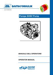
<strong>SH6V</strong><br />
POMPA A PISTONI ASSIALI A CILINDRATA<br />
VARIABILE PER CIRCUITO CHIUSO<br />
VARIABLE DISPLACEMENT AXIAL PISTON<br />
PUMP FOR CLOSED CIRCUIT<br />
COD. 04-0024-A26 E/1
INDICE / INDEX<br />
CARATTERISTICHE - FEATURES Pag. E/4<br />
CARATTERISTICHE TECNICHE - TECHNICAL SPECIFICATIONS Pag. E/5<br />
DATI TECNICI - TECHNICAL DATA Pag. E/7<br />
POMPA <strong>SH6V</strong> 75 / <strong>SH6V</strong> 75 PUMP Pag. E/8<br />
Codice di ordinazione - Ordering Code Pag. E/8<br />
Regolatore manuale a leva retroazionato HLR - HLR Manual leve control with feed-back Pag. E/12<br />
Regolatore manuale a leva retroazionato con sensore di posizione neutra HLS<br />
HLS Manual leve control with feed-back and neutral position micro switch Pag. E/13<br />
Regolatore idraulico proporzionale retroazionato HIR - HIR Hydraulic proportional control with feed-back Pag. E/14<br />
Regolatore idraulico proporzionale non retroazionato HIN - HIN Hydraulic proportional control without feed-back Pag. E/15<br />
Regolatore idraulico on-off HI2 - HI2 Hydraulic on-off control Pag. E/16<br />
Regolatore elettrico proporzionale retroazionato HER - HER Electric proportional control with feed-back Pag. E/17<br />
Regolatore elettrico proporzionale non retroazionato HEN - HEN Electric proportional control without feed-back Pag. E/18<br />
Regolatore elettrico on-off HE2 - HE2 Electric on-off control Pag. E/19<br />
Regolatore elettrico proporzionale retroazionato con comando idraulico d’emergenza HEH<br />
HEH Electric proportional control with hydraulic emergency override Pag. E/20<br />
Compensatore di pressione PC - PC Pressure compensator Pag. E/21<br />
Valvola di taglio elettrico TE - TE Electric Cut-Off valve Pag. E/21<br />
Filtro in pressione - Pressure Filter Pag. E/22<br />
Valvola BY-PASS - BY-PASS valve Pag. E/22<br />
Valvola SF per controllo automotive - SF speed related valve Pag. E/23<br />
Dimensioni pompa e regolatori - Pump and Controls dimensions Pag. E/24<br />
Dimensioni alberi - Shafts dimensions Pag. E/28<br />
Dimensioni pompa e accessori - Pump and accessories dimensions Pag. E/29<br />
Prese di moto passante - Through drives Pag. E/32<br />
Dimensioni pompa Tandem - Tandem combination dimensions Pag. E/33<br />
Dimensioni prese di moto - Through drives dimensions Pag. E/34<br />
POMPA <strong>SH6V</strong> 130 / <strong>SH6V</strong> 130 PUMP Pag. E/37<br />
Codice di ordinazione - Ordering Code Pag. E/37<br />
Regolatore manuale a leva retroazionato HLR - HLR Manual leve control with feed-back Pag. E/41<br />
Regolatore manuale a leva retroazionato con sensore di posizione neutra HLS<br />
HLS Manual leve control with feed-back and neutral position micro switch Pag. E/42<br />
Regolatore idraulico proporzionale retroazionato HIR - HIR Hydraulic proportional control with feed-back Pag. E/43<br />
Regolatore idraulico proporzionale non retroazionato HIN - HIN Hydraulic proportional control without feed-back Pag. E/44<br />
Regolatore idraulico on-off HI2 - HI2 Hydraulic on-off control Pag. E/45<br />
Regolatore elettrico proporzionale retroazionato HER - HER Electric proportional control with feed-back Pag. E/46<br />
Regolatore elettrico proporzionale non retroazionato HEN - HEN Electric proportional control without feed-back Pag. E/47<br />
Regolatore elettrico on-off HE2 - HE2 Electric on-off control Pag. E/48<br />
Regolatore elettrico proporzionale retroazionato con comando idraulico d’emergenza HEH<br />
HEH Electric proportional control with hydraulic emergency override Pag. E/49<br />
Compensatore di pressione PC - PC Pressure compensator Pag. E/50<br />
Valvola di taglio elettrico TE - TE Electric Cut-Off valve Pag. E/50<br />
Filtro in pressione - Pressure Filter Pag. E/51<br />
Valvola SF per controllo automotive - SF speed related valve Pag. E/52<br />
Dimensioni pompa e regolatori - Pump and Controls dimensions Pag. E/53<br />
Dimensioni alberi - Shafts dimensions Pag. E/57<br />
Dimensioni pompa e accessori - Pump and accessories dimensions Pag. E/58<br />
Prese di moto passante - Through drives Pag. E/60<br />
Dimensioni pompa Tandem - Tandem combination dimensions Pag. E/61<br />
Dimensioni prese di moto - Through drives dimensions Pag. E/63<br />
E/3
CARATTERISTICHE<br />
FEATURES<br />
Introduzione<br />
Le pompe a cilindrata variabile per circuito chiuso della serie<br />
<strong>SH6V</strong> sono del tipo a pistoni assiali a piatto inclinato con<br />
albero passante. Queste pompe sono state progettate per<br />
essere specificatamente impiegate in trasmissioni idrostatiche<br />
in circuito chiuso. La portata è proporzionale alla velocità di<br />
rotazione ed alla cilindrata. Essa aumenta con l’aumentare<br />
dell’angolo di inclinazione del piatto da 0 alla posizione<br />
massima, invertendo il senso d’inclinazione del piatto, la<br />
direzione della portata viene invertita. Le scelte tecnico<br />
costruttive consentono alla nuova unità di lavorare fino a<br />
pressioni di 420 bar.<br />
La nuova unità propone attualmente la seguente gamma di<br />
regolatori intercambiabili tra le varie cilindrate:<br />
• Manuale a leva retroazionato HLR.<br />
• Manuale a leva retroazionato con sensore di posizione HLS.<br />
• Idraulico proporzionale retroazionato HIR.<br />
• Idraulico proporzionale non retroazionato HIN.<br />
• Idraulico on-off HI2.<br />
• Elettrico proporzionale retroazionato HER.<br />
• Elettrico proporzionale non retroazionato HEN.<br />
• Elettrico on-off HE2.<br />
• Elettrico proporzionale retroazionato con comando idraulico<br />
d’emergenza HEH.<br />
La pompa incorpora due valvole limitatrici di pressione per la<br />
protezione del circuito dai sovraccarichi di pressione. Il circuito<br />
di sovralimentazione è costituito da una pompa a gerotor<br />
disponibile in tre diverse cilindrate adattabili alle diverse<br />
esigenze dell’impianto.<br />
Il progetto della pompa permette l’installazione di numerosi<br />
accessori, tra cui:<br />
• Compensatore di pressione.<br />
• Valvola di taglio pressione elettrica.<br />
• Valvole di taglio pressione combinate elettrica - idraulica.<br />
• Presa di moto passante con una vasta gamma di<br />
predisposizioni.<br />
• Filtro di carico in mandata della sovralimentazione.<br />
• Indicatore di intasamento del filtro elettrico o meccanico.<br />
• Valvola BY-PASS.<br />
• Valvola per controllo Automotive.<br />
E/4<br />
Introduction<br />
The <strong>SH6V</strong> series variable piston pumps for closed loop circuits<br />
are axial pistons pumps with swash plate design and through<br />
drive shaft on option. These pumps have been specifically<br />
designed for use in closed circuit hydrostatic transmissions. The<br />
delivery is proportional to the rotation speed and the swash plate<br />
angle. The delivery increases when swash plate’s angle of<br />
inclination increases from 0 to maximum position. Inverting the<br />
swash plate’s angle, the flow direction is inverted. The design<br />
choices allow the new unit to operate at pressures up to of 420<br />
bar [6090 psi].<br />
The series offers the following range of controls :<br />
• HLR Manual lever with feed-back.<br />
• HLS Manual lever with feed-back and neutral position micro<br />
switch<br />
• HIR Hydraulic proportional with feed-back.<br />
• HIN Hydraulic proportional without feed-back.<br />
• HI2 Hydraulic on-off.<br />
• HER Electric proportional with feed-back.<br />
• HEN Electric proportional without feed-back.<br />
• HE2 Electric on-off.<br />
• HEH Electric proportional with hydraulic emergency override.<br />
The pump has two built-in pressure relief valves to protect the<br />
circuit from pressure overloads. The charge pump circuit<br />
features a gerotor pump with three different displacement on<br />
option.<br />
The pump design allows the installation of many accessories,<br />
such as:<br />
• Hydraulic pressure compensator.<br />
• Electric cut-off valve.<br />
• Combined electric cut-off – hydraulic pressure compensator.<br />
• A wide range of through drive options.<br />
• Charge pump delivery pressure filter.<br />
• Electric or mechanical clogging sensor on the filter.<br />
• BY PASS valve.<br />
• Speed related valve.<br />
R<br />
axial piston
CARATTERISTICHE TECNICHE<br />
TECHNICAL SPECIFICATIONS<br />
Fluidi:<br />
Utilizzare fluidi a base minerale con additivi anticorrosione,<br />
antiossidanti e antiusura (HL o HM) con viscosità alla<br />
temperatura di esercizio di 15 ÷ 40 cSt. Una viscosità limite di<br />
800 cSt è ammissibile solo per brevi periodi in condizione di<br />
partenza a freddo. Non sono ammesse viscosità inferiori ai 10<br />
cSt. Viscosità comprese tra i 10 e i 15 cSt sono tollerate solo in<br />
casi eccezionali e per brevi periodi. Per maggiori dettagli<br />
consultare la sezione Fluidi e Filtrazione.<br />
Temperature:<br />
Non è consigliato il funzionamento dell'unità a pistoni con<br />
temperature del fluido idraulico superiori a 90 ºC (194 °F) e<br />
inferiori a -25 ºC (-13 °F). Per maggiori dettagli consultare la<br />
sezione Fluidi e Filtrazione.<br />
Filtrazione in aspirazione e mandata:<br />
Sulla unità <strong>SH6V</strong> è possibile montare il filtro sia sull’aspirazione<br />
che sulla mandata della pompa di sovralimentazione. Il filtro<br />
sulla mandata viene fornito dalla S.A.M. Hydraulik mentre per il<br />
filtro montato sull’aspirazione leggere quanto segue.<br />
Il filtro deve essere montato sull'ammissione della pompa di<br />
aspirazione. Si raccomanda di utilizzare un filtro con indicatore<br />
di intasamento con by-pass tappato e con grado di filtrazione di<br />
10 μm assoluti e caduta di pressione massima sull'elemento<br />
filtrante di 0.2 bar. Una corretta filtrazione contribuisce a<br />
prolungare la durata in esercizio dell'unità a pistoni. Per un<br />
corretto impiego dell'unità a pistoni la classe di contaminazione<br />
massima ammessa è 20/18/15 secondo la ISO 4406:1999.<br />
Pressione di aspirazione:<br />
La pressione minima sulla bocca di aspirazione della pompa di<br />
sovralimentazione è di 0.8 bar assoluti. All'avviamento e per<br />
brevi istanti è tollerata una pressione assoluta di 0.5 bar. La<br />
pressione sulla bocca di aspirazione non deve mai scendere al<br />
di sotto di tale valore.<br />
Pressione di esercizio:<br />
Pompa principale: La pressione massima continua ammissibile<br />
sulla bocca di mandata è di 420 bar con picchi di pressione di<br />
480 bar. Pompa di sovralimentazione: La pressione nominale è<br />
di 25 bar. La pressione massima ammissibile è di 40 bar.<br />
Pressione in carcassa:<br />
La pressione massima in carcassa è di 4 bar. Per brevi istanti<br />
all'avviamento della macchina è ammessa una pressione<br />
massima di 6 bar. Una pressione superiore può compromettere<br />
la durata e la funzionalità della guarnizione dell'albero in<br />
ingresso.<br />
Guarnizioni:<br />
Le guarnizioni standard utilizzate sulle pompe <strong>SH6V</strong> sono in<br />
FKM (Viton ®). Nel caso di impiego di fluidi speciali contattare la<br />
S.A.M. Hydraulik S.p.A.<br />
Limitazione della cilindrata:<br />
La pompa è dotata del dispositivo meccanico di limitazione della<br />
cilindrata. La limitazione viene ottenuta mediante due grani<br />
presenti sul servocomando, i quali limitano la corsa del pistone<br />
di comando.<br />
R<br />
axial piston<br />
Fluids:<br />
Use fluids with mineral oil basis and anticorrosive, antioxidant<br />
and wear preventing addition agents (HL or HM). Viscosity<br />
range at operating temperature must be of 15 ÷ 40 cSt. For<br />
short periods and upon cold start, a max.viscosity of 800 cSt is<br />
allowed. Viscosities less then 10 cSt are not allowed. A<br />
viscosity range of 10 ÷15 cSt is allowed for extreme operating<br />
conditions and for short periods only. For further information<br />
see at Fluids and Filtration section.<br />
Operating temperature:<br />
The operating temperature of the oil must be within -25 ºC ÷ 90<br />
ºC (-13 ºF ÷ 194 ºF). The running of the axial piston unit with oil<br />
temperature higher than 90 ºC (194 °F) or lower than -25 ºC (-<br />
13 °F) is not recommended. For further information see at<br />
Fluids and filtration section.<br />
Filtration:<br />
In the <strong>SH6V</strong> pump it is possible to provide a filter in the suction<br />
line but we recommend to use the optional pressure filter on<br />
the out-let line of the charge pump. The filter on the charge<br />
pump out-let line is supplied by S.A.M. Hydraulik while if the<br />
filter assembled in the suction line is used the following<br />
recommendation applies:<br />
Install the filter on the suction line of the auxiliary pump. We<br />
recommend to use filters with clogging indicator, no by-pass or<br />
with by-pass plugged and filter elementrating of 10 μm<br />
absolute. The maximum pressure drop on the filtration element<br />
must not exceed 0.2 bar [3 psi]. A correct filtration helps to<br />
extend the service life of axial piston units.In order to ensure a<br />
correct functioning of the unit, the max.permissible<br />
contamination class is 20/18/15 according to ISO 4406:1999.<br />
Suction pressure:<br />
The minimum absolute pressure on the auxiliary pump suction<br />
must be of 0.8 bar [11.6 absolute psi]. On cold starting and for<br />
short-periods an absolute pressure of 0.5 bar [7.25 psi] is<br />
allowed. In no case inlet pressure can be lower.<br />
Operating pressure:<br />
Main pump: The maximum permissible continuous pressure on<br />
pressure ports is 420 bar [6090 psi]. Peak pressure is 480 bar<br />
[6960 psi]. Charge pump: The nominal pressure is 25 bar [360<br />
psi]. Maximum admissible pressure is 40 bar [580 psi].<br />
Case drain pressure:<br />
Maximum case drain pressure is 4 bar [58 psi]. On cold starting<br />
and for short-term a pressure of 6 bar [86 psi] is allowed. A<br />
higher pressure can damage the input shaft seal or reduce its<br />
life.<br />
Seals:<br />
Standard seals used on <strong>SH6V</strong> pumps are of FKM (Viton ®).<br />
In case of use special fluids, contact S.A.M.Hydraulik S.p.A.<br />
Displacement limiting:<br />
The pump is equiped with the externally adjustable mechanical<br />
displacement limiting device. Displacement limitation is<br />
obtained by means of two setting screws which limit the control<br />
piston stroke.<br />
E/5
Capacità di carico albero d’ingresso:<br />
L'albero d’ingresso è in grado di sopportare sia carichi radiali<br />
sia assiali. I carichi massimi ammissibili riportati in tabella sono<br />
tali da garantire una durata dei supporti superiore all'80% della<br />
durata in assenza di carichi.<br />
Installazione:<br />
Le pompe possono essere installate in qualsiasi direzione e<br />
posizione. Per maggiori dettagli contattare la S.A.M. Hydraulik.<br />
E/6<br />
Cilindrata / Displacement 75<br />
Forza radiale<br />
Radial load<br />
Forza assiale<br />
Axial load<br />
Input shaft Radial and Axial loads:<br />
The input shaft can stand both radial and axial loads. The<br />
maximum permissible loads in the following table are calculated<br />
in such a way as to guarantee a service life of at least 80% of<br />
the service life of bearings to which no load is applied.<br />
Fq max<br />
Fax max<br />
N<br />
[lbf]<br />
N<br />
[lbf]<br />
2400<br />
[540]<br />
1900<br />
[428]<br />
130<br />
4600<br />
[1035]<br />
4300<br />
[967]<br />
Installation:<br />
<strong>SH6V</strong> series pumps can be installed in every position or direction.<br />
For further details contact S.A.M. Hydraulik.<br />
R<br />
axial piston
DATI TECNICI<br />
TECHNICAL DATA<br />
Dimensione / Size 75 130<br />
Cilindrata (1) / Displacement (1)<br />
Pressione / Pressure<br />
Velocità max / Max speed<br />
R<br />
axial piston<br />
Vg max<br />
Vg min<br />
cont. pnom<br />
picco / peak pmax<br />
cm 3 /giro<br />
[in 3 /rev]<br />
cm 3 /giro<br />
[in 3 /rev]<br />
bar<br />
[psi]<br />
bar<br />
[psi]<br />
55<br />
[3.35]<br />
0<br />
[0]<br />
400<br />
[5800]<br />
450<br />
[6525]<br />
75<br />
[4.57]<br />
100<br />
[6.1]<br />
0<br />
[0]<br />
420<br />
[6090]<br />
480<br />
[6960]<br />
128<br />
[7.8]<br />
Cont. nmax rpm 4000 3400 3000 2850<br />
int nmax rpm 4300 3600 3450 3300<br />
Velocità min / Min speed nmin rpm 500 500<br />
Portata massima a nmax / Max flow at nmax<br />
Potenza massima / Maximum power<br />
Coppia massima a Vg max / Max torque at Vg max<br />
Cont.<br />
int<br />
Cont.<br />
(pnom)<br />
picco/peak<br />
(pmax)<br />
Momento di inerzia / Moment of inertia J<br />
Peso (2) / Weight (2)<br />
Dati tecnici pompa sovralimentazione<br />
Charge pump technical data<br />
Cilindrata pompa di sovralimentazione<br />
Displacement charge pump<br />
Pressione di taratura sovralimentazione<br />
Charge pump setting pressure<br />
Pressione massima sovralimentazione<br />
Charge pump maximum pressure<br />
Potenza Cont. pompa sovralimentazione a 3400 rpm<br />
Charge pump power cont. at 3400 rpm<br />
Pressione consentita in carcassa<br />
Maximum Pressure in the housing<br />
(Valori teorici, senza considerare ηhm e ηv; valori arrotondati). Le<br />
condizioni di picco non devono durare più dell’ 1% di ogni minuto.<br />
Evitare il funzionamento continuo, contemporaneamente alla massima<br />
velocità e alla massima pressione.<br />
Note:<br />
(1) Le cilindrate 55 e 100 cm 3 /giro sono ottenute limitando la cilindrata<br />
massima. E’ possibile il raggiungimento della cilindrata di 81 e 134<br />
cm 3 /giro previo contatto con Uff.Tecnico per dati prestazionali<br />
(2) Valori indicativi.<br />
(3) Disponibile solo su cilindrate 55 e 75 cm 3 /giro.<br />
Cont.<br />
int<br />
qmax<br />
Tnom<br />
Tmax<br />
m<br />
l/min<br />
[U.S. gpm]<br />
cm 3 /giro<br />
[in 3 /rev]<br />
bar<br />
[psi]<br />
bar<br />
[psi]<br />
kW<br />
[hp]<br />
bar<br />
[psi]<br />
bar<br />
[psi]<br />
kW<br />
[hp]<br />
kW<br />
[hp]<br />
Nm<br />
[lbf·ft]<br />
Nm<br />
[lbf·ft]<br />
kg·m 2<br />
[lbf·ft 2 ]<br />
kg<br />
[lb]<br />
220<br />
[58.08]<br />
146.5<br />
[196.3]<br />
177.5<br />
[237.8]<br />
350<br />
[257]<br />
394<br />
[290]<br />
18 (3)<br />
[1.1] (3)<br />
2.2<br />
[2.95]<br />
0.014<br />
[0.34]<br />
51<br />
[112.5]<br />
255<br />
[67.32]<br />
170<br />
[227.8]<br />
202.5<br />
[271.3]<br />
478<br />
[352]<br />
537<br />
[396]<br />
23<br />
[1.4]<br />
22<br />
[319)]<br />
40<br />
[580]<br />
2.8<br />
[3.75]<br />
4<br />
[58]<br />
6<br />
[87]<br />
300<br />
[79.2]<br />
210<br />
[281]<br />
240<br />
[321]<br />
669<br />
[493]<br />
764<br />
[563]<br />
0.040<br />
[0.96]<br />
86<br />
[189.5]<br />
365<br />
[96.3]<br />
259<br />
[347]<br />
343<br />
[459]<br />
858<br />
[632]<br />
980<br />
[722]<br />
27<br />
[1.6]<br />
3.3<br />
[4.4]<br />
(Theorical values, without considering ηhm and ηv;approximate values).<br />
Peak operations must not excide 1% of every minute. Avoid<br />
continuously working at simultaneusly maximum pressure and<br />
maximum speed.<br />
Notes:<br />
(1) 3 3<br />
The displacements 55 and 100 cm /giro [3.3 and 6.1 in /rev] are<br />
obtained by maximun displacement limiting. It is possible to achieve<br />
the displacements 81 and 134 cm 3 /giro [4.9 and 8.1 in 3 /rev], please<br />
contact our technical service for the technical specifications.<br />
(2)<br />
Approximate values.<br />
(3) 3<br />
Available only with displacements 55 and 75 cm /giro [3.3 and 4.5<br />
in 3 /rev].<br />
E/7
CODICI DI ORDINAZIONE<br />
ORDERING CODE<br />
Le seguenti lettere o numeri del codice, sono state sviluppate<br />
per identificare tutte le configurazioni possibili delle pompe<br />
<strong>SH6V</strong> 75. Usare il seguente modulo per identificare le<br />
caratteristiche desiderate. Tutte le lettere o numeri del<br />
codice devono comparire in fase d’ordine. Si consiglia di<br />
leggere attentamente il catalogo prima di iniziare la<br />
compilazione del codice di ordinazione.<br />
1 - SERIE / SERIES<br />
E/8<br />
1<br />
<strong>SH6V</strong><br />
075<br />
Pompa a pistoni assiali a cilindrata variabile per circuito chiuso<br />
Variable displacement axial piston pump for closed circuit<br />
2 - CILINDRATA / DISPLACEMENT<br />
ME ISO<br />
SE SAE<br />
Cilindrata 75 cm 3 /giro<br />
Displacement [4.575 in 3 /rev]<br />
3 - VERSIONE / VERSION<br />
4 - ESTREMITÀ ALBERO / SHAFT END<br />
13<br />
AC<br />
06<br />
Scanalato Z14 - 12/24 DP<br />
Splined 14T - 12/24 DP<br />
Scanalato Z21 - 16/32 DP<br />
Splined 21T - 16/32 DP<br />
5 - FLANGIA / MOUNTING FLANGE<br />
DX<br />
SX<br />
2<br />
SAE-C 2/4 Fori<br />
SAE-C 2/4 Bolts<br />
Destra<br />
CW<br />
Sinistra<br />
CCW<br />
3 4<br />
5 6<br />
A Richiesta<br />
Upon Request<br />
6 - SENSO DI ROTAZIONE (VISTA LATO ALBERO) / DIRECTION OF ROTATION (VIEWED FROM SHAFT SIDE)<br />
7 - POMPA DI SOVRALIMENTAZIONE / CHARGE PUMP<br />
18 STANDARD<br />
23<br />
Cilindrata 23.1 cm 3 /giro<br />
Displacement [1.41 in 3 /rev]<br />
27<br />
Cilindrata 27.3 cm 3 /giro<br />
Displacement [1.647 in 3 Cilindrata 18 cm<br />
/rev]<br />
3 /giro<br />
Displacement [1.098 in 3 /rev]<br />
CODICE PRODOTTO / MODEL CODE<br />
7<br />
8<br />
<strong>SH6V</strong> 75<br />
8A<br />
9<br />
The following alphanumeric codes system has been developed<br />
to identify all of the configuration options for the <strong>SH6V</strong> 75<br />
pumps. Use the model code below to specify the desired<br />
features. All alphanumeric digits system of the code must be<br />
present when ordering. We recommend to carefully read the<br />
catalogue before filling the ordering code.<br />
10<br />
11<br />
12<br />
12A<br />
13<br />
14<br />
R<br />
15<br />
16<br />
17<br />
axial piston
1<br />
8 - REGOLATORE / CONTROL<br />
HLR<br />
HLS<br />
HIR<br />
HIN<br />
HI2<br />
HER<br />
HEN<br />
HE2<br />
HEH<br />
R<br />
Manuale a leva retroazionato<br />
Manual lever with feed-back<br />
Manuale a leva retroazionato con sensore di posizione neutra<br />
Manual lever with feed-back with neutral position micro switch<br />
Idraulico proporzionale retroazionato<br />
Hydraulic proportional with feed-back<br />
Idraulico proporzionale non retroazionato<br />
Hydraulic proportional without feed-back<br />
Idraulico on-off<br />
Hydraulic on-off<br />
Elettrico proporzionale retroazionato<br />
Electric proportional with feed-back<br />
Elettrico proporzionale non retroazionato<br />
Electric proportional without feed-back<br />
Elettrico on-off<br />
Electric on-off<br />
Elettrico proporzionale retroazionato con comando idraulico d’emergenza<br />
Electric proportional with emergency hydraulic override<br />
9 - VALVOLA DI MASSIMA PRESSIONE RAMO A / PRESSURE RELIEF VALVE SIDE A<br />
25<br />
250 bar<br />
[3625 psi]<br />
35<br />
350 bar<br />
[5075 psi]<br />
42<br />
420 bar<br />
[6090 psi]<br />
STANDARD<br />
10 - VALVOLA DI MASSIMA PRESSIONE RAMO B / PRESSURE RELIEF VALVE SIDE B<br />
25<br />
250 bar<br />
[3625 psi]<br />
35<br />
350 bar<br />
[5075 psi]<br />
42<br />
420 bar<br />
[6090 psi]<br />
STANDARD<br />
11 - VALVOLA DI MASSIMA PRESSIONE SOVRALIMENTAZIONE / CHARGE PRESSURE RELIEF VALVE<br />
20<br />
22<br />
25<br />
12 - VALVOLE DI TAGLIO / CUT-OFF VALVES<br />
XX<br />
PC<br />
TE<br />
EP<br />
2<br />
20 bar<br />
[290 psi]<br />
22 bar<br />
[319 psi]<br />
25 bar<br />
[362 psi]<br />
3 4<br />
Senza Valvola<br />
Without Cut-Off Valve<br />
Compensatore di pressione<br />
Pressure Compensator<br />
Taglio elettrico<br />
Electric Cut-Off<br />
Taglio elettrico + pressione<br />
Electric Cut-Off + Pressure Compensator<br />
axial piston<br />
5 6<br />
8A - CARATTERISTICA REGOLATORE<br />
CONTROL SPECIFICATIONS<br />
● Disponibile - Available / Non Disponibile - Not Available<br />
7<br />
8<br />
8A<br />
STANDARD<br />
STANDARD<br />
9<br />
10<br />
HLR HLS HIR<br />
11<br />
12<br />
12A<br />
HIN<br />
senza Valvole di taglio<br />
without Cut-Off valves<br />
13<br />
Regolatore / Control<br />
14<br />
HIN<br />
con Valvole di taglio<br />
with Cut-Off valves<br />
15<br />
16<br />
17<br />
HER HEN HE2 HEH<br />
00<br />
Caratteristica non necessaria<br />
None<br />
● ● ● ●<br />
/ / / / / /<br />
12<br />
24<br />
Tensione di alimentazione<br />
Voltage<br />
12(V)<br />
24(V) STANDARD<br />
/<br />
/<br />
/<br />
/<br />
/<br />
/<br />
/<br />
/<br />
/<br />
/<br />
/<br />
/<br />
●<br />
●<br />
●<br />
●<br />
●<br />
●<br />
●<br />
●<br />
05<br />
Ø 0.5 mm / Ø 0.019 in / / / /<br />
● ● / / / /<br />
07 Diametro Grani Strozzatori Ø 0.7 mm / Ø 0.027 in STANDARD / / / /<br />
/ ● / / / /<br />
08 Control orifice Diameter Ø 0.8 mm / Ø 0.031 in STANDARD / / / /<br />
● / / / / /<br />
09 Ø 0.9 mm / Ø 0.035 in / / / /<br />
● ● / / / /<br />
HI2<br />
E/9
12A - CARATTERISTICA VALVOLA DI TAGLIO / CUT-OFF VALVES FEATURE<br />
00<br />
XXX<br />
FM5<br />
FE5<br />
FM8<br />
FE8<br />
E/10<br />
1<br />
2<br />
Senza Valvola di Taglio (XX)<br />
(XX) Without Cut-Off Valve<br />
Caratteristica non necessaria<br />
Feature not necessary<br />
13 - FILTRO / FILTER<br />
3 4<br />
5 6<br />
Senza Filtro<br />
Without Filter<br />
Con sensore meccanico d’intasamento (5 bar)<br />
Mechanical clogging sensor [72.5 psi]<br />
Con sensore elettrico d’intasamento (5 bar)<br />
Electric clogging sensor [72.5 psi]<br />
Con sensore meccanico d’intasamento (8 bar)<br />
Mechanical clogging sensor [116 psi]<br />
Con sensore elettrico d’intasamento (8 bar)<br />
Electric clogging sensor [116 psi]<br />
14 - PREDISPOSIZIONI / THROUGH DRIVE<br />
7<br />
8<br />
8A<br />
Compensatore di pressione (PC)<br />
(PC) Pressare Compensator<br />
00 Bloccata / Locked<br />
10 100 bar [1450 psi]<br />
15 150 bar [2175 psi]<br />
20 200 bar [2900 psi]<br />
25 250 bar [3625 psi]<br />
30 300 bar [4350 psi]<br />
35 350 bar [5075 psi]<br />
38 380 bar [5510 psi]<br />
40 400 bar [5800 psi]<br />
STANDARD<br />
9<br />
10<br />
Valvola Taglio elettrico (TE)<br />
(TE) Electric Cut-Off Valve<br />
Tensione<br />
Voltage<br />
12 12 V<br />
11<br />
12<br />
24 24 V STANDARD<br />
XX<br />
Nessuna Predisposizione<br />
Without through drive<br />
SA SAE A = Z9 - 16/32 DP<br />
TA<br />
Predisposizione Tandem per assemblaggio mediante SAE A = Z9 - 16/32 DP<br />
Tandem through drive with flange SAE A = 9T - 16/32 DP<br />
SB SAE B = Z13 - 16/32 DP<br />
TB<br />
Predisposizione Tandem per assemblaggio mediante SAE B = Z13 - 16/32 DP<br />
Tandem through drive with flange SAE B = 13T - 16/32 DP<br />
TZ (1) Predisposizione Tandem per assemblaggio mediante SAE B-B = Z15 - 16/32 DP (Speciale per pompe SH5V 32/45/50/63)<br />
Tandem through drive with flange SAE B-B = 15T - 16/32 DP (Special for SH5V 32/45/50/63 pumps)<br />
TY (2) Predisposizione Tandem per assemblaggio mediante SAE B - DIN 5480 W35x2x30x16x9g (Speciale per pompe SH5V 50/63)<br />
Tandem through drive with flange SAE B - DIN 5480 W35x2x30x16x9g (Special for SH5V 50/63 pumps)<br />
BB SAE B-B = Z15 - 16/32 DP<br />
BT<br />
Predisposizione Tandem per assemblaggio mediante SAE B-B = Z15 - 16/32 DP<br />
Tandem through drive with flange SAE B-B = 15T - 16/32 DP<br />
SC SAE C = Z14 - 12/24 DP<br />
TC<br />
Predisposizione Tandem per assemblaggio mediante SAE C = Z14 - 12/24 DP<br />
Tandem through drive with flange SAE C = 14T - 12/24 DP<br />
TX<br />
Predisposizione Tandem per assemblaggio mediante SAE C = Z21 - 16/32 DP<br />
Tandem through drive with flange SAE C = 21T - 16/32 DP<br />
CC SAE C-C = Z17 - 12/24 DP<br />
G2 GR2 L=4<br />
G3 GR3<br />
(1) Tandem <strong>SH6V</strong> 75 + SH5V 32/45/50/63 con albero Z15 16/32 DP<br />
(2) Tandem <strong>SH6V</strong> 75 + SH5V 50/63 con albero DIN 5480 W35x2x30x16x9g<br />
Pressione di taratura<br />
Pressure Setting<br />
12A<br />
13<br />
14<br />
R<br />
15<br />
STANDARD<br />
(1) Tandem <strong>SH6V</strong> 75 + SH5V 32/45/50/63 with shaft Z15 16/32 DP<br />
(2) Tandem <strong>SH6V</strong> 75 + SH5V 50/63 with shaft DIN 5480 W35x2x30x16x9g<br />
16<br />
17<br />
Valvola Taglio elettrico + pressione (EP)<br />
(EP) Pressure Compensator + Electric Cut-Off<br />
Tensione<br />
Voltage Pressione di taratura<br />
12V 24V<br />
Pressure Setting<br />
21 41 Bloccata / Locked<br />
22 42 100 bar [1450 psi]<br />
23 43 150 bar [2175 psi]<br />
24 44 200 bar [2900 psi]<br />
25 45 250 bar [3625 psi]<br />
26 46 300 bar [4350 psi]<br />
27 47 350 bar [5075 psi]<br />
29 49 380 bar [5510 psi]<br />
28 48 400 bar [5800 psi]<br />
axial piston
1<br />
15 - LIMITAZIONE CILINDRATA RAMO A / DISPLACEMENT LIMITATION SIDE A<br />
075 STANDARD<br />
000÷074 Da 0 cm3 /giro a 74 cm 3 /giro<br />
From 0 cm 3 /rev to 74 cm 3 Non Richiesta<br />
Not Required<br />
/rev<br />
16 - LIMITAZIONE CILINDRATA RAMO B / DISPLACEMENT LIMITATION SIDE B<br />
075 STANDARD<br />
000÷074 Da 0 cm3 /giro a 74 cm 3 /giro<br />
From 0 cm 3 /rev to 74 cm 3 Non Richiesta<br />
Not Required<br />
/rev<br />
XX<br />
01<br />
S4<br />
R<br />
2<br />
17 - OPZIONI / OPTIONS<br />
Non Richieste<br />
Not Required<br />
Valvola By Pass<br />
By Pass valve<br />
3 4<br />
Valvola SF per controllo Automotive (partenza 1000 giri/min)<br />
SF Speed related valve (starting 1000 rpm)<br />
axial piston<br />
5 6<br />
7<br />
8<br />
8A<br />
9<br />
10<br />
11<br />
12<br />
12A<br />
Non disponibile con pompa di sovr. 27.3 cm 3 /giro (27), regolare HIN, e Valvole di taglio TE o<br />
EP<br />
Not available with 1.647 in 3 /rev (27) charge pump, HIN control, and TE or EP Cut-off valves<br />
13<br />
14<br />
15<br />
16<br />
17<br />
E/11
REGOLATORE MANUALE A LEVA RETROAZIONATO<br />
MANUAL LEVER CONTROL WITH FEED-BACK<br />
La pompa assume una cilindrata direttamente proporzionale<br />
all'angolo impostato dalla leva. La retroazione sente l'eventuale<br />
errore di posizionamento del piatto oscillante e tende a<br />
correggerlo automaticamente tramite il servocomando. Per la<br />
relazione angolo-cilindrata vedere il diagramma.<br />
Senso di rotazione:Correlazione tra il senso di rotazione della<br />
pompa (visto dal lato albero) e l’azionamento del regolatore.<br />
E/12<br />
R<br />
HLR<br />
The displacement of the pump is directly proportional to the<br />
angle of rotation of the lever. The feedback system feels the<br />
position of the swashplate and works automatically to<br />
compensate for a positioning error. The diagram below shows<br />
the ralationship between angle and displacement.<br />
La coppia da applicare alla leva di controllo è compresa tra 1 e<br />
2.45 Nm.<br />
The torque necessary at the control lever is between 1 and 2.45<br />
Nm [0.737 and 1.80 lbf·ft].<br />
Direction of rotation: Correlation between direction of rotation<br />
(shaft view) control and direction of flow.<br />
axial piston
REGOLATORE MANUALE A LEVA RETROAZIONATO CON SENSORE DI POSIZIONE NEUTRA<br />
MANUAL LEVER CONTROL WITH FEED-BACK AND NEUTRAL POSITION MICRO SWITCH<br />
La pompa assume una cilindrata direttamente proporzionale<br />
all'angolo impostato dalla leva. La retroazione sente l'eventuale<br />
errore di posizionamento del piatto oscillante e tende a<br />
correggerlo automaticamente tramite il servocomando. Il<br />
sensore di posizione è costruito con logica PNP, di<br />
conseguenza il sensore si trova in stato di Tbassa quando la leva<br />
è in posizione neutra. Qualsiasi movimento della leva porta il<br />
sensore in stato di Talta.<br />
Per la relazione angolo-cilindrata vedere il diagramma.<br />
Caratteristiche tecniche sensore:<br />
Principio di funzionamento induttivo<br />
Funzione di uscita PNP<br />
Tensione d’esercizio 10÷34 V<br />
Corrente a vuoto Io ≤10<br />
Corrente d’esercizio nominale Ie 200 mA<br />
Campo di temperatura –25°C +85°C<br />
Grado di protezione IP67<br />
Segnale in uscita<br />
Talta > T d.c. –2V<br />
Tbassa < 2V<br />
Senso di rotazione: Correlazione tra il senso di rotazione della<br />
pompa (visto dal lato albero) e l’azionamento del regolatore.<br />
R<br />
axial piston<br />
HLS<br />
The displacement of the pump is directly proportional to the<br />
angle of the lever. The feedback system feels the position of<br />
the swashplate and works automatically to compensate for a<br />
positioning error. The micro switch is built as PNP, therefore<br />
the sensor is in Tlow when the lever is in neutral position. Any<br />
movemet of the lever brings the sensor in Thigh.<br />
The diagram below shows the ralationship between angle and<br />
displacement.<br />
Electronic Sensor technical features:<br />
Inductive principle<br />
Output current PNP<br />
Voltage 10÷34 V<br />
Current in neutral Io ≤10<br />
Nominal working current Ie 200 mA<br />
Temperature range –25°C +85°C<br />
Enclosure IP67<br />
Output signal:<br />
Thigh > T d.c. –2V<br />
Tlow < 2V<br />
La coppia da applicare alla leva di controllo è compresa tra 1 e 2.45 Nm.<br />
The torque necessary at the control lever is between 1 and 2.45 Nm [0.737 and 1.80 lbf·ft].<br />
Direction of rotation: Correlation between direction of rotation<br />
(shaft view) control and direction of flow.<br />
E/13
REGOLATORE IDRAULICO PROPORZIONALE RETROAZIONATO<br />
HYDRAULIC PROPORTIONAL CONTROL WITH FEED-BACK<br />
La pompa assume una cilindrata proporzionale alla pressione<br />
sugli attacchi Y1 oppure Y2 attraverso i quali si definisce oltre<br />
all'entità della portata anche il senso di mandata. La<br />
retroazione sente l'eventuale errore di posizionamento del<br />
piatto oscillante e tende a correggerlo automaticamente tramite<br />
il servocomando. Per l'alimentazione di Y1 ed Y2 si può<br />
sfruttare la pressione di sovralimentazione prelevabile dalla<br />
porta GS. La suddetta pressione dovrà poi essere controllata<br />
da un manipolatore o da una valvola riduttrice di pressione per<br />
il pilotaggio di Y1 e Y2 (non forniti).<br />
Pressione di pilotaggio = 6÷18 bar (su Y1, Y2)<br />
Inizio regolazione = 6 bar<br />
Fine regolazione = 18 bar (Massima cilindrata)<br />
N.B.<br />
La tolleranza sulla pressione di pilotaggio è di ± 10% del valore<br />
di fondo scala.<br />
Senso di rotazione:Correlazione tra il senso di rotazione della<br />
pompa (visto dal lato albero) e l’azionamento del regolatore.<br />
E/14<br />
R<br />
HIR<br />
The pump displacement is proportional to the pilot pressure on<br />
Y1 or Y2 ports, which also affect flow direction. The feedback<br />
system feels the position of the swashplate and works<br />
automatically to compensate for a positioning error. Piloting can<br />
be provided by boost pressure from GS port. The piloting<br />
pressure will then have to be controlled by a joystick or by a<br />
pressure reducing valve (not supplied).<br />
Pilot pressure = 6÷18 bar [87÷261 psi](at ports Y1, Y2)<br />
Start of control = 6 bar [87 psi]<br />
End of control = 18 bar [261 psi](Max displacement)<br />
Note<br />
The tolerance on piloting pressure is ± 10% of maximum value.<br />
Direction of rotation: Correlation between direction of rotation<br />
(shaft view) control and direction of flow.<br />
axial piston
REGOLATORE IDRAULICO PROPORZIONALE NON RETROAZIONATO<br />
HYDRAULIC PROPORTIONAL CONTROL WITHOUT FEED-BACK<br />
La pompa assume una cilindrata proporzionale alla pressione<br />
sugli attacchi Y1 oppure Y2 attraverso i quali si definisce oltre<br />
all'entità della portata anche il senso di mandata. Comando<br />
influenzato dalla pressione di esercizio. A parità di segnale<br />
d’ingresso (pressione di pilotaggio) la pompa può variare<br />
leggermente la cilindrata e la portata erogata all’aumentare della<br />
pressione d’esercizio. Per l'alimentazione del manipolatore si<br />
può sfruttare la pressione di sovralimentazione prelevabile dalla<br />
porta GS. La suddetta pressione dovrà poi essere regolata da<br />
un manipolatore o da una valvola riduttrice di pressione per il<br />
pilotaggio di Y1 e Y2 (non forniti). Per la scelta del grano da<br />
utilizzare, in funzione del tempo di risposta richiesto, vedasi la<br />
tabella sotto riportata.<br />
Pressione di pilotaggio = 6÷14 bar (su Y1, Y2)<br />
Inizio regolazione = 6 bar<br />
Fine regolazione = 14 bar (Massima cilindrata)<br />
Pilot pressure = 6÷14 bar [87÷203 psi](at ports Y1, Y2)<br />
Start of control = 6 bar [87 psi]<br />
End of control = 14 bar [203 psi](Max displacement)<br />
Senso di rotazione:Correlazione tra il senso di rotazione della<br />
pompa (visto dal lato albero) e l’azionamento del regolatore.<br />
R<br />
HIN<br />
Grano forato<br />
Orifice dimension<br />
Tempi di risposta su comando HIN<br />
HIN control response time<br />
axial piston<br />
Vg min→Vg max<br />
300 bar [4350 psi]<br />
Vg max→Vg min<br />
300 bar [4350 psi]<br />
Ø 0.5 mm<br />
3.6 sec. 6.5 sec.<br />
[Ø 0.019 in]<br />
Ø 0.7 mm (*)<br />
2 sec. 3.1 sec.<br />
[Ø 0.027 in] (*)<br />
Ø 0.8 mm (**)<br />
1.7 sec. 2.7 sec<br />
[Ø 0.031 in] (**)<br />
Ø 0.9 mm<br />
1.6 sec. 2.2 sec.<br />
[Ø 0.035 in]<br />
Le prove si sono svolte con la temperatura dell’olio a 45°÷47° C e la<br />
temperatura della pompa a 50°÷55° C - olio ISO Vg 46.<br />
Values obtained with oil temperature 45°÷47° C and pump temperature<br />
of 50°÷55° C - oil ISO Vg 46.<br />
(*) (STANDARD) con valvole di taglio<br />
(STANDARD) with cut-off valves<br />
(**) (STANDARD) senza valvole di taglio<br />
(STANDARD) without cut-off valves<br />
HIN<br />
The pump displacement is proportional to the pilot pressure on<br />
Y1 or Y2 piloting ports, which also affect flow direction. The<br />
flow is also influenced by the working pressure. With a given<br />
input signal (piloting pressure) the pump can slightly vary the<br />
displacement and the flow when working pressure increases.<br />
Feeding pressure to the control joystick can be provided by<br />
charge pressure from GS port. The piloting pressure must then<br />
be controlled by said joystick or by a pressure reducing valve<br />
(not supplied). The orifice dimensions must be choosed in<br />
function of the response time required, see the table below.<br />
HIN con valvole di taglio<br />
HIN with Cut-off valves<br />
N.B. / Note<br />
La tolleranza sulla pressione di pilotaggio è di ± 10% del valore di fondo scala / The tolerance on piloting pressure is ± 10% of maximum value.<br />
Direction of rotation: Correlation between direction of rotation<br />
(shaft view) control and direction of flow.<br />
E/15
REGOLATORE IDRAULICO ON-OFF<br />
HYDRAULIC ON-OFF<br />
Alimentando uno dei due attacchi Y1 e Y2, la pompa si porta<br />
alla cilindrata massima. Togliendo l'alimentazione la pompa si<br />
porta in annullamento di portata. Per l'alimentazione di Y1 ed<br />
Y2 si può sfruttare la pressione di sovralimentazione<br />
prelevabile dalla porta GS. La suddetta pressione dovrà poi<br />
essere controllata da un manipolatore (non fornito).<br />
Pressione di pilotaggio minima = 18 bar (su Y1, Y2)<br />
Pressione di pilotaggio massima = 250 bar (su Y1, Y2)<br />
N.B.<br />
La tolleranza sulla pressione di pilotaggio è di ± 10% del valore<br />
di fondo scala.<br />
Senso di rotazione: Correlazione tra il senso di rotazione della<br />
pompa (visto dal lato albero) e l’azionamento del regolatore.<br />
E/16<br />
R<br />
HI2<br />
By piloting one of the ports Y1 and Y2, the pump swivels to<br />
maximum displacement. Piloting off the port will result in<br />
swivelling back the pump to zero displacement position. Piloting<br />
can be provided by boost pressure from GS port. The piloting<br />
pressure will then have to be controlled by a joystick (not<br />
supplied).<br />
Minimum pilot pressure = 18 bar [261 psi](at ports Y1, Y2)<br />
Maximum pilot pressure = 250 bar [3625 psi](at ports Y1, Y2)<br />
Note<br />
The tolerance on piloting pressure is ± 10% of maximum value.<br />
Direction of rotation: Correlation between direction of rotation<br />
(shaft view) control and direction of flow.<br />
axial piston
REGOLATORE ELETTRICO PROPORZIONALE RETROAZIONATO<br />
ELECTRIC PROPORTIONAL CONTROL WITH FEED-BACK<br />
La pompa assume una cilindrata proporzionale alla corrente di<br />
alimentazione di uno dei due magneti installati sulla pompa. La<br />
retroazione sente l'eventuale errore di posizionamento del piatto<br />
oscillante e tende a correggerlo automaticamente tramite il<br />
servocomando. La corrente di alimentazione dei due<br />
elettromagneti proporzionali deve essere controllata da una<br />
scheda di regolazione esterna ed è consigliabile utilizzare la<br />
ns.scheda tipo VPD/AD specifica per <strong>SH6V</strong>. L'alimentazione<br />
dell'uno o dell'altro elettromagnete definisce il senso di<br />
mandata.Gli elettromagneti standard sono del tipo proporzionale<br />
a 24V c.c. corrente massima 1A. (Opzionali elettromagneti 12V<br />
c.c. corrente massima 2A). Per movimentazioni di sola<br />
emergenza è comunque possibile comandare i solenoidi<br />
direttamente con una tensione 24V c.c. (ovvero 12V c.c.)<br />
escludendo la scheda.<br />
Solenoide 24V:<br />
Corrente min. 200 mA max 600 mA<br />
Solenoide 12V:<br />
Corrente min. 400 mA max 1200 mA<br />
N.B.<br />
La tolleranza sulla corrente di pilotaggio è di ± 10% del valore di<br />
fondo scala.<br />
Senso di rotazione: Correlazione tra il senso di rotazione della<br />
pompa (visto dal lato albero) e l’azionamento del regolatore.<br />
R<br />
axial piston<br />
HER<br />
The displacement of the pump is directly proportional to the<br />
input current of one of the two proportional solenoids. The<br />
feedback system feels the position of the swashplate and works<br />
automatically to compensate for a positioning error. The input<br />
current of the two proportional solenoids must be controlled by<br />
an external amplifier card and it is recommended to use our<br />
amplifier type VPD/AD specific for <strong>SH6V</strong>. Flow direction<br />
depends on which solenoid is energized. Standard solenoids<br />
are proportional at 24V d.c. max. current 1A. (Optional<br />
solenoids 12V d.c. max. current 2A). For emergency operation<br />
only it is however possible to control solenoids directly with 24V<br />
d.c.voltage (or 12V d.c.), by-passing the amplifier.<br />
Solenoid 24V:<br />
Current min. 200 mA max 600 mA<br />
Solenoid 12V:<br />
Current min. 400 mA max 1200 mA<br />
Note<br />
The tolerance on piloting current is ± 10% of maximum value.<br />
Direction of rotation: Correlation between direction of rotation<br />
(shaft view) control and direction of flow.<br />
E/17
REGOLATORE ELETTRICO PROPORZIONALE NON RETROAZIONATO<br />
ELECTRIC PROPORTIONAL CONTROL WITHOUT FEED-BACK<br />
La pompa assume una cilindrata proporzionale alla corrente di<br />
alimentazione di uno dei due magneti installati sulla pompa.<br />
Comando influenzato dalla pressione di esercizio. A parità di<br />
segnale d’ingresso (corrente di pilotaggio) la pompa può<br />
variare leggermente la cilindrata e la portata erogata<br />
all’aumentare della pressione d’esercizio. La corrente di<br />
alimentazione dei due elettromagneti proporzionali deve<br />
essere controllata da una scheda di regolazione esterna ed è<br />
consigliabile utilizzare la ns.scheda tipo VPD/AD specifica per<br />
<strong>SH6V</strong>. L'alimentazione dell'uno o dell'altro elettromagnete<br />
definisce il senso di mandata.Gli elettromagneti standard sono<br />
del tipo proporzionale a 24V c.c. corrente massima 1A.<br />
(Opzionali elettromagneti 12V c.c. corrente massima 2A). Per<br />
movimentazioni di sola emergenza è comunque possibile<br />
comandare i solenoidi direttamente con una tensione 24V c.c.<br />
(ovvero 12V c.c.) escludendo la scheda.<br />
Solenoide 24V:<br />
Corrente min. 300 mA max 650 mA<br />
Solenoide 12V:<br />
Corrente min. 600 mA max 1300 mA<br />
N.B.<br />
La tolleranza sulla corrente di pilotaggio è di ± 10% del valore<br />
di fondo scala.<br />
Senso di rotazione: Correlazione tra il senso di rotazione<br />
della pompa (visto dal lato albero) e l’azionamento del<br />
regolatore.<br />
E/18<br />
R<br />
HEN<br />
The displacement of the pump is directly proportional to the<br />
input current of one of the two proportional solenoids. Flow is<br />
also influenced by the working pressure. With a given input<br />
signal (piloting current) the pump can slightly vary the<br />
displacement and the flow when working pressure increases.<br />
The input current of the two proportional solenoids must be<br />
controlled by an external amplifier card and it is recommended<br />
to use our amplifier type VPD/AD specific for <strong>SH6V</strong>. Flow<br />
direction depends on which solenoid is energized. Standard<br />
solenoids are proportional 24V d.c. max. current 1A. (Optional<br />
solenoids 12V d.c. max. current 2A). For emergency operation<br />
only it is however possible to control solenoids directly with 24V<br />
d.c.voltage (or 12V d.c.), by-passing the amplifier.<br />
Solenoid 24V:<br />
Current min. 300 mA max 650 mA<br />
Solenoid 12V:<br />
Current min. 600 mA max 1300 mA<br />
Note<br />
The tolerance on piloting current is ± 10% of maximum value.<br />
Direction of rotation: Correlation between direction of rotation<br />
(shaft view) control and direction of flow.<br />
axial piston
REGOLATORE ELETTRICO ON-OFF<br />
ELECTRIC ON-OFF<br />
Alimentando uno dei due elettromagneti ON-OFF (standard 24V<br />
c.c. opzionale 12V c.c.), la pompa si porta alla cilindrata<br />
massima nel senso di mandata corrispondente al magnete<br />
eccitato. Togliendo l'alimentazione la pompa si porta in<br />
annullamento di portata.<br />
Senso di rotazione: Correlazione tra il senso di rotazione della<br />
pompa (visto dal lato albero) e l’azionamento del regolatore.<br />
R<br />
axial piston<br />
HE2<br />
By switching on one of the ON-OFF solenoids (standard 24V<br />
d.c. optional 12V d.c.), the pump swivels to maximum<br />
displacement in the corresponding output flow direction.<br />
Switching off the stated solenoid will result in swivelling back<br />
the pump to zero displacement position.<br />
Direction of rotation: Correlation between direction of rotation<br />
(shaft view) control and direction of flow.<br />
E/19
REGOLATORE ELETTRICO PROPORZIONALE CON COMANDO IDRAULICO D’EMERGENZA<br />
ELECTRIC PROPORTIONAL CONTROL WITH HYDRAULIC EMERGENCY OVERRIDE<br />
Le caratteristiche elettriche di questo regolatore sono simili a<br />
quelle del regolatore HER. Ad esso si aggiunge la possibilità di<br />
agire sulla cilindrata della pompa anche mediante una<br />
pressione di pilotaggio sugli attacchi Y1 ed Y2. La corrente di<br />
alimentazione dei due elettromagneti proporzionali deve<br />
essere controllata da una scheda di regolazione esterna ed è<br />
consigliabile utilizzare la ns.scheda tipo VPD/AD specifica per<br />
<strong>SH6V</strong>. L'azionamento idraulico del regolatore HEH è stato<br />
concepito come azionamento di emergenza per permettere di<br />
regolare la cilindrata della pompa in caso di avaria del circuito<br />
elettrico. In funzionamento di emergenza una pressione di<br />
pilotaggio di 15 bar è necessaria per portare la pompa in<br />
cilindrata massima.<br />
Attenzione:<br />
1) Gli attacchi Y1 e Y2 non devono avere pressione residua<br />
durante il normale funzionamento del regolatore elettrico (a<br />
scarico diretto in serbatoio).<br />
Senso di rotazione: Correlazione tra il senso di rotazione<br />
della pompa (visto dal lato albero) e l’azionamento del<br />
regolatore.<br />
E/20<br />
R<br />
HEH<br />
This control has the same electric proportional features of HER<br />
control, but it also has an emergency hydraulic proportional<br />
control capability when a pilot pressure on Y1 and Y2 ports. The<br />
input current of the two proportional solenoids must be<br />
controlled by an external amplifier card and it is recommended<br />
to use our amplifier type VPD/AD specific for <strong>SH6V</strong>. Hydraulic<br />
operation of HEH control is meant to be an emergency device to<br />
control displacement of the pump in case of a breakdown of the<br />
electric circuit. A pilot pressure of 15 bar [218 psi] is required to<br />
swivel the pump to max displacement in emergency operation.<br />
Warning:<br />
1) Y1 and Y2 ports must not have any back pressure durino<br />
normal electric control operation (vented to tank).<br />
Direction of rotation: Correlation between direction of rotation<br />
(shaft view) control and direction of flow.<br />
axial piston
COMPENSATORE DI PRESSIONE<br />
PRESSURE COMPENSATOR<br />
La valvola compensatrice di pressione impedisce che le valvole<br />
di massima pressione intervengano durante i sovraccarichi di<br />
pressione portando la pompa a cilindrata ridotta. La valvola<br />
permette di mantenere costante la pressione nel circuito al<br />
valore di taratura. Si consiglia l'impiego della valvola in<br />
trasmissioni con frequenti picchi di pressione pari al valore<br />
massimo di taratura delle valvole di massima pressione o in<br />
trasmissioni dimensionate alla potenza massima della pompa.<br />
La valvola di taglio pressione deve essere tarata 20÷30 bar<br />
inferiore al valore di taratura delle valvole di massima pressione<br />
della pompa. Campo di taratura:100÷400 bar .<br />
NOTA: La valvola compensatrice di<br />
pressione è applicabile alla pompa<br />
<strong>SH6V</strong> standard e può essere<br />
combinata con la valvola TE (EP)<br />
Valvola EP Valve<br />
VALVOLA DI TAGLIO ELETTRICO<br />
ELECTRIC CUT OFF VALVE<br />
La valvola di taglio elettrico, flangiabile direttamente al corpo<br />
della pompa <strong>SH6V</strong>, annulla la cilindrata della pompa quando<br />
viene tolta l'alimentazione all'elettromagnete ON/OFF della<br />
valvola. La valvola è stata studiata per le applicazioni soggette a<br />
norme di sicurezza che impongono l'arresto della macchina in<br />
caso di assenza di un segnale elettrico di consenso. La tensione<br />
di alimentazione dell'elettromagnete è di 24V c.c. (opzionale 12V<br />
c.c.).<br />
NOTA: La valvola di taglio elettrico è<br />
applicabile alla pompa <strong>SH6V</strong><br />
standard e può essere combinata<br />
con la valvola PC (EP).<br />
Valvola EP Valve<br />
R<br />
axial piston<br />
PC<br />
The pressure compensator valve is meant to avoid opening of<br />
the relief valves: whenever working pressure reaches the PC<br />
valve setting, the swashplate is swivelled back reducing flow.<br />
The valve allows to maintain a constant pressure in the circuit<br />
at the setting value. It is advisable to fit the cut-off valve to all<br />
system where pressure peaks close to the relief valves setting<br />
value occur or in hydraulic systems engineered to the<br />
maximum pump pressure. It is recommended to set the<br />
pressure cut-off valve at 20÷30 bar [290÷435 psi] lower than<br />
the high pressure relief valve setting. Setting range:100÷400<br />
bar [1450÷5800 psi].<br />
Note: The pressure compensator<br />
valve can be mounted on standard<br />
<strong>SH6V</strong> pump and it can be combined<br />
with TE (EP) valve<br />
TE<br />
The electric cut-off valve, directly flangeable on <strong>SH6V</strong> pump<br />
housing, swivels back to zero the pump flow when power<br />
supply to the ON/OFF solenoid is cut-off. This valve has been<br />
designed for applications subject to safety rules, which<br />
required stopping of the machine in case of no electric signal.<br />
Feed voltage is 24V d.c. (optional 12V d.c.).<br />
Note: The electric cut-off valve can<br />
be assembled on standard <strong>SH6V</strong><br />
pump and it can be combined with<br />
PC (EP) valve<br />
E/21
FILTRO IN PRESSIONE<br />
PRESSURE FILTER<br />
Al fine di garantire il mantenimento della condizioni di<br />
contaminazione del fluido ottimali le unità <strong>SH6V</strong> possono<br />
essere dotate di un filtro posizionato sulla bocca di mandata<br />
della pompa di sovralimentazione. Attraverso l’elemento<br />
filtrante passerà esclusivamente la portata che reintegrerà l’olio<br />
perso a causa del drenaggio, tutta la portata in eccesso, che<br />
verrà messa a scarico dalla valvola di sovralimentazione, non<br />
sarà quindi filtrata, in questo modo si garantisce una maggiore<br />
durata del filtro. L’elemento presenta un setto filtrante in fibra<br />
composita. Il sistema prevede l’adozione degli indicatori<br />
d’intasamento del filtro (Standard 5 bar - Optional 8 bar) sia in<br />
versione elettrici (Connettore DIN 43650) che meccanici. È<br />
possibile combinare il filtro con le valvole di taglio pressione sia<br />
elettriche che idrauliche.<br />
E/22<br />
Sensore Meccanico / Mechanical Sensor<br />
Valvola BY - PASS<br />
BY - PASS valve<br />
La valvola By-Pass permette, in caso di necessità, di mettere<br />
in collegamento le bocche A e B.<br />
Per ottenere l’apertura della valvola, allentare il dado di<br />
bloccaggio e svitare di 6 giri il grano.<br />
In order to guarantee an optimum fluid contamination level in the<br />
closed loop the <strong>SH6V</strong> can be equipped with a filter positioned on<br />
the delivery outlet of the charge pump. Only the flow necessary<br />
to reintegrate the lost oil due to leakage will pass through the<br />
filter, all the excess flow is not filtered and discharged through<br />
the pump drain line. In this way a longer life of the filter is<br />
achieved. The filter contains a composite fibre filtering element.<br />
An electrical (Connector DIN 43650) and mechanical filter<br />
clogging sensors (Standard 5 bar [72.5 psi] - Optional 8 bar [116<br />
psi]) are available. It’s possible to combine the filter with both<br />
cut-off valves.<br />
Sensore Elettrico / Electrical Sensor<br />
Contatti in scambio<br />
Max carico resistivo<br />
Max carico induttivo<br />
SPDT<br />
Max resistive load<br />
Max inductive load<br />
C.A.\ A.C. 125-250 V 1 A 1 A<br />
C.C.\ D.C. 30 V 2 A 2 A<br />
C.C.\ D.C. 50 V 0,5 A 0,5 A<br />
C.C.\ D.C. 75 V 0,25 A 0,25 A<br />
C.C.\ D.C. 125 V 0,2 A 0,03 A<br />
The By-pass valve allows, if necessary, to connect the pressure<br />
port line A and B.<br />
To open the valve unlock the locking nut and turn the screw 6<br />
turns counter-clockwise.<br />
BY-PASS<br />
R<br />
axial piston
Valvola SF per controllo Automotive<br />
SF speed related valve<br />
Il funzionamento della pompa dotata di valvola SF prevede due<br />
fasi distinte e precisamente:<br />
• Presa diretta : L’unità non deve erogare portata al regime di<br />
rotazione minimo del diesel, all’incremento della velocità di<br />
rotazione si raggiunge un valore di partenza (campo di<br />
regolazione previsto 700 ÷ 1100 giri/min - standard 1000 giri/<br />
min - da indicare in fase d’ordine) che consente all’unità<br />
d’incrementare la portata, fino al raggiungimento della Vgmax.<br />
Il comando della pompa deve essere posizionato verso la<br />
massima cilindrata.<br />
• Proporzionalità di portata : Mediante un comando standard si<br />
ha la possibilità di variare in modo proporzionale la cilindrata<br />
dell’unità come se si usufruisse di un’unità standard. In<br />
questa fase per garantire il raggiungimento della cilindrata<br />
massima, disponibile sulla pompa, è indispensabile impostare<br />
il regime di rotazione del diesel ad un valore superiore a<br />
quello necessario al raggiungimento della Vgmax nel<br />
funzionamento come presa diretta.<br />
E possibile abbinare alla valvola SF le valvole di taglio e il filtro.<br />
Non è possibile abbinare la valvola SF con la pompa di sovralimentazione da 27<br />
cm 3 /giro.<br />
ATTENZIONE: nel caso in cui insieme alla valvola SF venga applicato anche il<br />
filtro in pressione, si prega di tenere presente che in caso di collasso o intasamento<br />
dello stesso si può verificare una diminuzione della velocità di partenza del<br />
comando, con conseguenze potenzialmente pericolose. Si raccomanda pertanto la<br />
sostituzione dell'elemento filtrante ad intervalli regolari, e comunque non superiori<br />
a quanto indicato nelle norme generali di manutenzione.<br />
R<br />
Con valvole di taglio<br />
With Cut-off valve<br />
axial piston<br />
Con filtro<br />
With filter<br />
The pump equipped with the SF valve can work in two modes:<br />
• Speed related : when the Diesel engine is idling the pump<br />
does not give any output flow. Increasing the engine speed<br />
the control starting point is reached (setting range of the<br />
control starting: 700 ÷ 1100 rpm - standard 1000 rpm) and<br />
from then on the pump gives a flow proportional to the rpm<br />
increase until it reaches the maximum displacement. To<br />
achieve this mode the pump primary control (manual,<br />
hydraulic or electronic) must be always in the fully open<br />
position.<br />
• Proportional control of the output flow: the engine rpm must<br />
be set to a constant speed higher than the one at which the<br />
pump reaches the Vgmax in the speed related mode (see<br />
diagram below), if so, it is possible to operate the primary<br />
control as a proportional control (manual, hydraulic or<br />
electronic) from zero to Vgmax in the usual way.<br />
CURVA REGOLAZIONE CILINDRATA<br />
DISPLACEMENT VARIATION CURVES<br />
It is possible to mount the cut-off valve and filter on the SF valve. It is not<br />
possible to use the SF valve with 27 cm 3 /giro [1.647 in 3 /rev] charge pump.<br />
WARNING: if the SF valve is used together with the boost pressure filter option,<br />
be aware that if the filter cartridge is partially clogged or collapsed the SF valve<br />
starting RPM could be reduced, causing potentially dangerous situations. We<br />
therefore strongly recommend to change the filter cartridges regularly, with at<br />
least the intervals recommended in the general information section of the<br />
catalogue.<br />
Con valvole di taglio + filtro<br />
With Cut-off valve + filter<br />
E/23
DIMENSIONI POMPA E REGOLATORI<br />
PUMP AND CONTROLS DIMENSIONS<br />
Pompa <strong>SH6V</strong> 75 - Flangia SAE C 2÷4 Fori - Regolatore HLR<br />
<strong>SH6V</strong> 75 Pump - Mounting flange SAE C 2÷4 Bolts - HLR Control<br />
A-B: Linee in pressione / Pressure ports - 1" SAE 6000<br />
L1-L2: Attacco drenaggio carcassa / Case drain port - 3/4 G (BSPP) Prof/Deep 17 [0.66]<br />
L3: Attacco drenaggio carcassa / Case drain port - 3/4 G (BSPP) Prof/Deep 15 [0.59]<br />
FA1-FA2: Aspirazione bocca pompa di sovralimentazione / Charge pump suction port - 1" G (BSPP) Prof/Deep 21 [0.82]<br />
GA-GB: Attacco manometrico linee in pressione / Pressure gauge - 1/4 G (BSPP) Prof/Deep 13 [0.511]<br />
GS: Attacco manometro pressione di sovralimentazione / Charge pressure gauge - 1/4 G (BSPP) Prof/Deep 13 [0.511]<br />
PS: Attacco manometro pressione regolatore / Control pressure gauge port - 1/4 G (BSPP) Prof/Deep 14 [0.551]<br />
Z1-Z2: Sfiati aria / Air bleeds port - 1/8 G (BSPP) Prof/Deep 10 [0.393]<br />
X1-X2: Attacco manometro pressione di regolazione / Stroking chamber gauge port - 1/4 G (BSPP) Prof/Deep 14 [0.551]<br />
S: Sfiato aria - attacco manometro / air bleed case pressure gauge port - 1/4 G (BSPP) Prof/Deep 13 [0.511]<br />
GT: Attacco manometro pressione di aspirazione / Boost inlet pressure gauge - 1/4 G (BSPP) Prof/Deep 13 [0.511]<br />
V1: Strozzatore regolabile / Adjustable throttle valve<br />
E/24<br />
R<br />
axial piston
Pompa <strong>SH6V</strong> 75 - Flangia SAE C 2÷4 Fori - Regolatore HLS<br />
<strong>SH6V</strong> 75 Pump - Mounting flange SAE C 2÷4 Bolts - HLS Control<br />
V1: Strozzatore variabile / Adjustable throttle valve<br />
Pompa <strong>SH6V</strong> 75 - Flangia SAE C 2÷4 Fori - Regolatore HIR<br />
<strong>SH6V</strong> 75 Pump - Mounting flange SAE C 2÷4 Bolts - HIR Control<br />
Y1-Y2: Attacchi pilotaggio comando / Control piloting pressure ports - 1/4 G (BSPP)<br />
S1-V1: Strozzatore variabile / Adjustable throttle valve<br />
Pompa <strong>SH6V</strong> 75 - Flangia SAE C 2÷4 Fori - Regolatore HIN<br />
<strong>SH6V</strong> 75 Pump - Mounting flange SAE C 2÷4 Bolts - HIN Control<br />
Y1-Y2: Attacchi pilotaggio comando / Control piloting pressure ports - 1/4 G (BSPP)<br />
V1: Strozzatore variabile / Adjustable throttle valve<br />
R<br />
axial piston<br />
E/25
Pompa <strong>SH6V</strong> 75 - Flangia SAE C 2÷4 Fori - Regolatore HIN con valvole di taglio<br />
<strong>SH6V</strong> 75 Pump - Mounting flange SAE C 2÷4 Bolts - HIN Control with Cut-off valves<br />
Y1-Y2: Attacchi pilotaggio comando / Control piloting pressure ports - 1/4 G (BSPP)<br />
V1: Strozzatore variabile / Adjustable throttle valve<br />
Pompa <strong>SH6V</strong> 75 - Flangia SAE C 2÷4 Fori - Regolatore HI2<br />
<strong>SH6V</strong> 75 Pump - Mounting flange SAE C 2÷4 Bolts - HI2<br />
Y1-Y2: Attacchi pilotaggio comando / Control piloting pressure ports - 1/4 G (BSPP)<br />
Pompa <strong>SH6V</strong> 75 - Flangia SAE C 2÷4 Fori - Regolatore HER<br />
<strong>SH6V</strong> 75 Pump - Mounting flange SAE C 2÷4 Bolts - HER Control<br />
S1-V1: Strozzatore variabile / Adjustable throttle valve<br />
E/26<br />
R<br />
axial piston
Pompa <strong>SH6V</strong> 75 - Flangia SAE C 2÷4 Fori - Regolatore HEN<br />
<strong>SH6V</strong> 75 Pump - Mounting flange SAE C 2÷4 Bolts - HEN Control<br />
V1: Strozzatore variabile / Adjustable throttle valve<br />
Pompa <strong>SH6V</strong> 75 - Flangia SAE C 2÷4 Fori - Regolatore HE2<br />
<strong>SH6V</strong> 75 Pump - Mounting flange SAE C 2÷4 Bolts - HE2 Control<br />
V1: Strozzatore variabile / Adjustable throttle valve<br />
Pompa <strong>SH6V</strong> 75 - Flangia SAE C 2÷4 Fori - Regolatore HEH<br />
<strong>SH6V</strong> 75 Pump - Mounting flange SAE C 2÷4 Bolts - HEH Control<br />
Y1-Y2: Attacchi pilotaggio comando / Control piloting pressure ports - 1/4 G (BSPP)<br />
S1-V1: Strozzatore variabile / Adjustable throttle valve<br />
R<br />
axial piston<br />
E/27
DIMENSIONI ALBERI<br />
SHAFTS DIMENSIONS<br />
AC<br />
SCANALATO / SPLINED SAE 1 - 3/8”<br />
21T 16/32 DP - FLAT ROOT CLASS 5<br />
ANSI B92.1a - 1976<br />
E/28<br />
13<br />
SCANALATO / SPLINED SAE 1 - 1/4”<br />
14T 12/24 DP - FLAT ROOT CLASS 5<br />
ANSI B92.1a - 1976<br />
R<br />
axial piston
DIMENSIONI POMPA E ACCESSORI<br />
PUMP AND ACCESSORIES DIMENSIONS<br />
Pompa <strong>SH6V</strong> 75 - Flangia SAE C 2÷4 Fori - Filtro<br />
<strong>SH6V</strong> 75 Pump - Mounting flange SAE C 2÷4 Bolts - Filter<br />
Pompa <strong>SH6V</strong> 75 - Flangia SAE C 2÷4 Fori - Filtro+ Taglio elettrico (TE)<br />
<strong>SH6V</strong> 75 Pump - Mounting flange SAE C 2÷4 Bolts - Filter + Cut-off electric valve (TE)<br />
Pompa <strong>SH6V</strong> 75 - Flangia SAE C 2÷4 Fori - Filtro+ Taglio pressione (PC)<br />
<strong>SH6V</strong> 75 Pump - Mounting flange SAE C 2÷4 Bolts - Filter + Cut-off pressure valve (PC)<br />
R<br />
axial piston<br />
Filtro Versione elettrica: Connettore DIN 43650<br />
Electric clogging indicator: Connector DIN 43650<br />
Filtro Versione elettrica: Connettore DIN 43650<br />
Electric clogging indicator: Connector DIN 43650<br />
Filtro Versione elettrica: Connettore DIN 43650<br />
Electric clogging indicator: Connector DIN 43650<br />
E/29
Pompa <strong>SH6V</strong> 75 - Flangia SAE C 2÷4 Fori - Filtro+ Taglio elettrico - Taglio pressione (EP)<br />
<strong>SH6V</strong> 75 Pump - Mounting flange SAE C 2÷4 Bolts - Filter + Cut-off electric valve - Cut-off pressure valve (EP)<br />
Pompa <strong>SH6V</strong> 75 - Flangia SAE C 2÷4 Fori - Taglio elettrico (TE)<br />
<strong>SH6V</strong> 75 Pump - Mounting flange SAE C 2÷4 Bolts - Cut-off electric valve (TE)<br />
Pompa <strong>SH6V</strong> 75 - Flangia SAE C 2÷4 Fori - Taglio pressione (PC)<br />
<strong>SH6V</strong> 75 Pump - Mounting flange SAE C 2÷4 Bolts - Cut-off pressure valve (PC)<br />
E/30<br />
Filtro Versione elettrica: Connettore DIN 43650<br />
Electric clogging indicator: Connector DIN 43650<br />
R<br />
axial piston
Pompa <strong>SH6V</strong> 75 - Flangia SAE C 2÷4 Fori - Taglio elettrico - Taglio pressione (EP)<br />
<strong>SH6V</strong> 75 Pump - Mounting flange SAE C 2÷4 Bolts - Cut-off electric valve - Cut-off pressure valve (EP)<br />
Pompa <strong>SH6V</strong> 75 - Flangia SAE C 2÷4 Fori - BY-PASS (01)<br />
<strong>SH6V</strong> 75 Pump - Mounting flange SAE C 2÷4 Bolts - BY-PASS (01)<br />
Pompa <strong>SH6V</strong> 75 - Flangia SAE C 2÷4 Fori - Valvola SF per controllo Automotive<br />
<strong>SH6V</strong> 75 Pump - Mounting flange SAE C 2÷4 Bolts - SF Speed related valve<br />
R<br />
Taratura giri di partenza<br />
Control starting setting screw<br />
axial piston<br />
Dado SEAL-LOCK Ch.22<br />
Nut SEAL-LOCK (22mm spanner)<br />
Vite senza testa esagono incassato Ch.6<br />
Grub screw (6mm allen-key)<br />
E/31
PRESE DI MOTO PASSANTE<br />
THROUGH DRIVES<br />
La pompa <strong>SH6V</strong> 75 può essere fornita con presa di moto<br />
passante per il trascinamento di una seconda pompa (un’altra<br />
<strong>SH6V</strong> 75 o di un altro tipo). Le flangie disponibili sono:<br />
• Flangie per pompe ad ingranaggi G2 e G3<br />
• Flangie SAE A, SAE B, SAE C, SAE B-B e SAE C-C<br />
• Flangie TANDEM<br />
Le coppie massime applicabili all’albero della prima pompa e<br />
prelevabili attraverso le prese di moto sono indicate nella<br />
tabella seguente.<br />
ATTENZIONE: Il valore di coppia risultante sull’albero della<br />
prima pompa è dato dalla somma delle coppie assorbite dalle<br />
varie pompe che compongono il sistema.<br />
Cilindrata / Size 75<br />
Albero di entrata<br />
Drive Shaft<br />
Coppia max albero di entrata<br />
Drive Shaft max torque<br />
Coppia massima presa di moto<br />
Through drive max torque<br />
E/32<br />
ME<br />
MC<br />
Nm<br />
[lbf·ft]<br />
Nm<br />
[lbf·ft]<br />
<strong>SH6V</strong> 75 pump can be supplied with through drive. The through<br />
drive can driving with a second <strong>SH6V</strong> 75 or a pump of other<br />
kind. Available flanges are:<br />
• Standard G2 and G3 gear pump flange<br />
• SAE A, SAE B, SAE C, SAE B-B and SAE C-C flange<br />
• TANDEM flange<br />
The maximum permissible torques on drive shaft of the first<br />
pump and the maximum through drive torques are listed in the<br />
table below.<br />
WARNING: The effective torque value on the shaft of first pump<br />
is given by the sum of the torques required from each pump<br />
making the system.<br />
AC<br />
(Z21 16/32 DP)<br />
950<br />
[700]<br />
665<br />
[490]<br />
13<br />
(Z14 12/24 DP )<br />
R<br />
620<br />
[457]<br />
620<br />
[457]<br />
axial piston
DIMENSIONI POMPA TANDEM<br />
TANDEM COMBINATION DIMENSIONS<br />
Pompa<br />
Pump<br />
R<br />
axial piston<br />
Alberi per pompe in tandem/Shafts for combination pumps<br />
Configurazioni<br />
Configuration<br />
75/75<br />
Alberi / Shafts AC AC<br />
Alberi / Shafts AC 13<br />
Alberi / Shafts(*) 13 13<br />
Attenzione: Le predisposizioni TA-TB-BT-TC-TX-TZ-TY devono<br />
essere utilizzate nella configurazione della prima pompa nei<br />
seguenti casi:<br />
1. Pompa Tandem assemblata.<br />
2. Pompa singola per eventuale assemblaggio Tandem con<br />
seconda pompa S.A.M. Hydraulik.<br />
Esempio:<br />
• Se si vuole acquistare un Tandem assemblato composto da<br />
due pompe <strong>SH6V</strong> 75 e la seconda pompa monta un albero AC<br />
(Z21 - 16/32 DP), la prima pompa dovrà essere configurata<br />
con la predisposizione TX.<br />
• Se si vuole acquistare una pompa <strong>SH6V</strong> 75 singola per<br />
assemblarla in Tandem con una seconda pompa <strong>SH6V</strong> 75 con<br />
un albero 13 (Z14 - 12/24 DP), la pompa dovrà essere<br />
configurata con la predisposizione TC.<br />
1 a<br />
1st.<br />
2 a<br />
2nd.<br />
Warning: The TA-TB-BT-TC-TX-TZ-TY through drives must be<br />
used in the configuration of the first pump in the following cases:<br />
1. Tandem pump combination.<br />
2. Single pump for possible Tandem pump combination with<br />
S.A.M. Hydraulik second pump.<br />
Example:<br />
• If it is needed to purchase a Tandem pump combination with<br />
two <strong>SH6V</strong> 75 pumps and the second pump has the AC (21T<br />
- 16/32 DP) shaft, the first pump will must have the TX<br />
through drive.<br />
• If it is needed to purchase a single <strong>SH6V</strong> 75 pump for<br />
Tandem pump combination with a <strong>SH6V</strong> 75 second pump<br />
with 13 (14T - 12/24 DP) shaft, the pump will must have the<br />
TC through drive.<br />
E/33
DIMENSIONI PRESE DI MOTO<br />
THROUGH DRIVES DIMENSIONS<br />
Flangia SAE A (SA)<br />
SAE A (SA) Flange<br />
Flangia SAE B (SB) - SAE B-B (BB)<br />
SAE B (SB) - SAE B-B (BB) Flange<br />
Flangia SAE C (SC) - SAE C-C (CC)<br />
SAE C (SC) - SAE C-C (CC) Flange<br />
E/34<br />
R<br />
axial piston
Flangia G2<br />
G2 Flange<br />
Flangia G3<br />
G3 Flange<br />
R<br />
axial piston<br />
E/35
E/36<br />
R<br />
axial piston
CODICI DI ORDINAZIONE<br />
ORDERING CODE<br />
Le seguenti lettere o numeri del codice, sono state sviluppate<br />
per identificare tutte le configurazioni possibili delle pompe<br />
<strong>SH6V</strong> 130. Usare il seguente modulo per identificare le<br />
caratteristiche desiderate. Tutte le lettere o numeri del codice<br />
devono comparire in fase d’ordine. Si consiglia di leggere<br />
attentamente il catalogo prima di iniziare la compilazione del<br />
codice di ordinazione.<br />
1<br />
R<br />
2<br />
1 - SERIE / SERIES<br />
<strong>SH6V</strong><br />
3 4<br />
axial piston<br />
5 6<br />
Pompa a pistoni assiali a cilindrata variabile per circuito chiuso<br />
Variable displacement axial piston pump for closed circuit<br />
2 - CILINDRATA / DISPLACEMENT<br />
130<br />
Cilindrata 128 cm 3 /giro<br />
Displacement [7.8 in 3 /rev]<br />
3 - VERSIONE ATTACCHI / PORTS<br />
ME ISO<br />
SE SAE<br />
4 - ESTREMITÀ ALBERO / SHAFT END<br />
BF<br />
BE<br />
BG<br />
BH<br />
BI<br />
BL<br />
Scanalato Z23 - 16/32 DP<br />
Splined 23T - 16/32 DP<br />
Scanalato Z27 - 16/32 DP<br />
Splined 27T - 16/32 DP<br />
Scanalato Z15 - 8/16 DP<br />
Splined 15T - 8/16 DP<br />
Scanalato Z13 - 8/16 DP<br />
Splined 13T - 8/16 DP<br />
Scanalato W45x2x30x21<br />
Splined W45x2x30x21<br />
Scanalato W40x2x30x18<br />
Splined W40x2x30x18<br />
5 - FLANGIA / MOUNTING FLANGE<br />
11<br />
DC<br />
SAE-D 2/4 Fori<br />
SAE-D 2/4 Bolts<br />
Flangia di conversione da SAE-D a SAE-C<br />
Conversion flange from SAE-D to SAE-C<br />
● Disponibile - Available / Non Disponibile - Not Available<br />
CODICE PRODOTTO / MODEL CODE<br />
7<br />
<strong>SH6V</strong> 130<br />
8<br />
8A<br />
A Richiesta<br />
Upon Request<br />
9<br />
The following alphanumeric codes system has been developed<br />
to identify all of the configuration options for the <strong>SH6V</strong> 130<br />
pumps. Use the model code below to specify the desired<br />
features. All alphanumeric digits system of the code must<br />
be present when ordering. We recommend to carefully read<br />
the catalogue before filling the ordering code.<br />
10<br />
11<br />
12<br />
12A<br />
13<br />
14<br />
ESTREMITÀ ALBERO / SHAFT END<br />
15<br />
BF BE BG BH BI BL<br />
● ● ● ● ● ●<br />
● / / ● / /<br />
16<br />
17<br />
E/37
6 - SENSO DI ROTAZIONE (VISTA LATO ALBERO) / DIRECTION OF ROTATION (VIEWED FROM SHAFT SIDE)<br />
DX<br />
SX<br />
23<br />
27<br />
E/38<br />
1<br />
Destra<br />
CW<br />
Sinistra<br />
CCW<br />
7 - POMPA DI SOVRALIMENTAZIONE / CHARGE PUMP<br />
Cilindrata 23.1 cm 3 /giro<br />
Displacement [1.41 in 3 /rev]<br />
Cilindrata 27.3 cm 3 /giro<br />
Displacement [1.647 in 3 /rev]<br />
8 - REGOLATORE / CONTROL<br />
HLR<br />
HLS<br />
HIR<br />
HIN<br />
HI2<br />
HER<br />
HEN<br />
HE2<br />
HEH<br />
2<br />
3 4<br />
5 6<br />
STANDARD<br />
Manuale a leva retroazionato<br />
Manual lever with feed-back<br />
Manuale a leva retroazionato con sensore di posizione neutra<br />
Manual lever with feed-back with neutral position micro switch<br />
Idraulico proporzionale retroazionato<br />
Hydraulic proportional with feed-back<br />
Idraulico proporzionale non retroazionato<br />
Hydraulic proportional without feed-back<br />
Idraulico on-off<br />
Hydraulic on-off<br />
Elettrico proporzionale retroazionato<br />
Electric proportional with feed-back<br />
Elettrico proporzionale non retroazionato<br />
Electric proportional without feed-back<br />
Elettrico on-off<br />
Electric on-off<br />
Elettrico proporzionale retroazionalo con comando idraulico d’emergenza<br />
Electric proportional with emergency hydraulic override<br />
8A - CARATTERISTICA REGOLATORE<br />
CONTROL SPECIFICATIONS<br />
00<br />
Caratteristica non necessaria<br />
None<br />
12 Tensione di alimentazione<br />
Voltage<br />
05<br />
Diametro Grani Strozzatori<br />
Control orifices Diameter<br />
● Disponibile - Available / Non Disponibile - Not Available<br />
9 - VALVOLA DI MASSIMA PRESSIONE RAMO A / PRESSURE RELIEF VALVE SIDE A<br />
25<br />
250 bar<br />
[3625 psi]<br />
35<br />
350 bar<br />
[5075 psi]<br />
42<br />
420 bar<br />
[6090 psi]<br />
STANDARD<br />
7<br />
8<br />
8A<br />
9<br />
10<br />
11<br />
12<br />
12A<br />
HLR HLS HIR HI2<br />
Regolatore / Control<br />
HIN<br />
con Valvole di taglio<br />
with Cut-Off valves<br />
HER HEN HE2 HEH<br />
● ● ● ●<br />
/ / / / /<br />
12(V) / / / /<br />
/ ● ● ● ●<br />
24 24(V) STANDARD / / / /<br />
/ ● ● ● ●<br />
Ø 0.5 mm / Ø 0.019 in / / / /<br />
● / / / /<br />
07 Ø 0.7 mm / Ø 0.027 in / / / /<br />
● / / / /<br />
09 Ø 0.9 mm / Ø 0.035 in STANDARD / / / /<br />
● / / / /<br />
13<br />
14<br />
R<br />
15<br />
16<br />
17<br />
axial piston
1<br />
10 - VALVOLA DI MASSIMA PRESSIONE RAMO B / PRESSURE RELIEF VALVE SIDE B<br />
25<br />
250 bar<br />
[3625 psi]<br />
35<br />
350 bar<br />
[5075 psi]<br />
42<br />
420 bar<br />
[6090 psi]<br />
STANDARD<br />
11 - VALVOLA DI MASSIMA PRESSIONE SOVRALIMENTAZIONE / CHARGE PRESSURE RELIEF VALVE<br />
20<br />
22<br />
25<br />
12 - VALVOLE DI TAGLIO / CUT-OFF VALVES<br />
PC<br />
EP<br />
R<br />
2<br />
20 bar<br />
[290 psi]<br />
22 bar<br />
[319 psi]<br />
25 bar<br />
[362 psi]<br />
3 4<br />
Compensatore di pressione<br />
Pressure Compensator<br />
Taglio elettrico + pressione<br />
Electric cut-off + Pressure Compensator<br />
axial piston<br />
5 6<br />
7<br />
8<br />
8A<br />
STANDARD<br />
STANDARD<br />
12A - CARATTERISTICA VALVOLA DI TAGLIO / CUT-OFF VALVES FEATURE<br />
13 - FILTRO / FILTER<br />
XXX<br />
FM5<br />
FE5<br />
FM8<br />
FE8<br />
Compensatore di pressione (PC)<br />
(PC) Pressare Compensator<br />
00 Bloccata / Locked<br />
10 100 bar [1450 psi]<br />
15 150 bar [2175 psi]<br />
20 200 bar [2900 psi]<br />
25 250 bar [3625 psi]<br />
30 300 bar [4350 psi]<br />
35 350 bar [5075 psi]<br />
38 380 bar [5510 psi]<br />
40 400 bar [5800 psi]<br />
Senza Filtro<br />
Without Filter<br />
Con sensore meccanico d’intasamento (5 bar)<br />
Mechanical clogging sensor [72.5 psi]<br />
Con sensore elettrico d’intasamento (5 bar)<br />
Electric clogging sensor [72.5 psi]<br />
Con sensore meccanico d’intasamento (8 bar)<br />
Mechanical clogging sensor [116 psi]<br />
Con sensore elettrico d’intasamento (8 bar)<br />
Electric clogging sensor [116 psi]<br />
Pressione di taratura<br />
Pressure Setting<br />
STANDARD<br />
9<br />
10<br />
11<br />
12<br />
12A<br />
13<br />
14<br />
15<br />
Valvola Taglio elettrico + pressione (EP)<br />
(EP) Pressure Compensator + Electric Cut-Off<br />
Tensione<br />
Voltage<br />
12V 24V<br />
Pressione di taratura<br />
Pressure Setting<br />
21 41 Bloccata / Locked<br />
22 42 100 bar [1450 psi]<br />
23 43 150 bar [2175 psi]<br />
24 44 200 bar [2900 psi]<br />
25 45 250 bar [3625 psi]<br />
26 46 300 bar [4350 psi]<br />
27 47 350 bar [5075 psi]<br />
29 49 380 bar [5510 psi]<br />
28 48 400 bar [5800 psi]<br />
16<br />
17<br />
E/39
14 - PREDISPOSIZIONI / THROUGH DRIVE<br />
E/40<br />
1<br />
XX<br />
Nessuna Predisposizione<br />
Without through drive<br />
SA SAE A = Z9 - 16/32 DP<br />
TA<br />
Predisposizione Tandem per assemblaggio mediante SAE A = Z9 - 16/32 DP<br />
Tandem through drive with flange SAE A = 9T - 16/32 DP<br />
SB SAE B = Z13 - 16/32 DP<br />
TB<br />
Predisposizione Tandem per assemblaggio mediante SAE B = Z13 - 16/32 DP<br />
Tandem through drive with flange SAE B = 13T - 16/32 DP<br />
TZ (1) Predisposizione Tandem per assemblaggio mediante SAE B-B = Z15 - 16/32 DP (Speciale per pompe SH5V 32/45/50/63)<br />
Tandem through drive with flange SAE B-B = 15T - 16/32 DP (Special for SH5V 32/45/50/63 pumps)<br />
TY (2) Predisposizione Tandem per assemblaggio mediante SAE B - DIN 5480 W35x2x30x16x9g (Speciale per pompe SH5V 50/63)<br />
Tandem through drive with flange SAE B - DIN 5480 W35x2x30x16x9g (Special for SH5V 50/63 pumps)<br />
BB SAE B-B = Z15 - 16/32 DP<br />
BT<br />
Predisposizione Tandem per assemblaggio mediante SAE B-B = Z15 - 16/32 DP<br />
Tandem through drive with flange SAE B-B = 15T - 16/32 DP<br />
SC SAE C = Z14 - 12/24 DP<br />
TC<br />
Predisposizione Tandem per assemblaggio mediante SAE C = Z14 - 12/24 DP<br />
Tandem through drive with flange SAE C = 14T - 12/24 DP<br />
CC SAE C-C = Z17 - 12/24 DP<br />
CT<br />
Predisposizione Tandem per assemblaggio mediante SAE C-C = Z17 - 12/24 DP<br />
Tandem through drive with flange SAE C-C = 17T - 12/24 DP<br />
SD SAE D = Z13 - 8/16 DP<br />
TD<br />
Predisposizione Tandem per assemblaggio mediante SAE D = Z13 - 8/16 DP<br />
Tandem through drive with flange SAE D = 13T - 8/16 DP<br />
TJ<br />
Predisposizione Tandem per assemblaggio mediante SAE D = Z23 - 16/32 DP<br />
Tandem through drive with flange SAE D = 23T - 16/32 DP<br />
G2 GR2 L=4<br />
G3 GR3<br />
(1) Tandem <strong>SH6V</strong> 130 + SH5V 32/45/50/63 con albero Z15 16/32 DP<br />
(2) Tandem <strong>SH6V</strong> 130 + SH5V 50/63 con albero DIN 5480 W35x2x30x16x9g<br />
15 - LIMITAZIONE CILINDRATA RAMO A / DISPLACEMENT LIMITATION SIDE A<br />
128 STANDARD<br />
000÷127 Da 0 cm3 /giro a 127 cm 3 /giro<br />
From 0 cm 3 /rev to 127 cm 3 Non Richiesta<br />
Not Required<br />
/rev<br />
16 - LIMITAZIONE CILINDRATA RAMO B / DISPLACEMENT LIMITATION SIDE B<br />
128 STANDARD<br />
000÷127 Da 0 cm3 /giro a 127 cm 3 /giro<br />
From 0 cm 3 /rev to 127 cm 3 Non Richiesta<br />
Not Required<br />
/rev<br />
17 - OPZIONI / OPTIONS<br />
XX<br />
S4<br />
2<br />
3 4<br />
5 6<br />
Non Richieste<br />
Not Required<br />
Valvola SF per controllo Automotive (partenza 1000 giri/min)<br />
SF Speed related valve (starting 1000 rpm)<br />
7<br />
8<br />
8A<br />
9<br />
10<br />
11<br />
12<br />
12A<br />
R<br />
STANDARD<br />
(1) Tandem <strong>SH6V</strong> 130 + SH5V 32/45/50/63 with shaft Z15 16/32 DP<br />
(2) Tandem <strong>SH6V</strong> 130 + SH5V 50/63 with shaft DIN 5480 W35x2x30x16x9g<br />
Non disponibile con pompa di sovr. 27.3 cm 3 /giro (27), regolare HIN, Valvole taglio EP e predisposizione<br />
SAE-D.<br />
Not available with 1.647 in 3 /rev (27) charge pump, HIN control, EP Cut-off valves and SAE-D through drive<br />
13<br />
14<br />
15<br />
16<br />
17<br />
axial piston
REGOLATORE MANUALE A LEVA RETROAZIONATO<br />
MANUAL LEVER CONTROL WITH FEED-BACK<br />
La pompa assume una cilindrata direttamente proporzionale<br />
all'angolo impostato dalla leva. La retroazione sente l'eventuale<br />
errore di posizionamento del piatto oscillante e tende a<br />
correggerlo automaticamente tramite il servocomando. Per la<br />
relazione angolo-cilindrata vedere il diagramma.<br />
La coppia da applicare alla leva di controllo è compresa tra 1 e<br />
2.45 Nm.<br />
The torque necessary at the control lever is between 1 and 2.45<br />
Nm [0.737 and 1.80 lbf·ft].<br />
Senso di rotazione:Correlazione tra il senso di rotazione della<br />
pompa (visto dal lato albero) e l’azionamento del regolatore.<br />
R<br />
axial piston<br />
HLR<br />
The displacement of the pump is directly proportional to the<br />
angle of the lever. The feedback system feels the position of<br />
the swashplate and works automatically to compensate for a<br />
positioning error. The diagram below shows the ralationship<br />
between angle and displacement.<br />
Direction of rotation: Correlation between direction of rotation<br />
(shaft view) control and direction of flow.<br />
E/41
REGOLATORE MANUALE A LEVA RETROAZIONATO CON SENSORE DI POSIZIONE NEUTRA<br />
MANUAL LEVER CONTROL WITH FEED-BACK AND NEUTRAL POSITION MICRO SWITCH<br />
La pompa assume una cilindrata direttamente proporzionale<br />
all'angolo impostato dalla leva. La retroazione sente l'eventuale<br />
errore di posizionamento del piatto oscillante e tende a<br />
correggerlo automaticamente tramite il servocomando. Il<br />
sensore di posizione è costruito con logica PNP, di<br />
conseguenza il sensore si trova in stato di Tbassa quando la leva<br />
è in posizione neutra. Qualsiasi movimento della leva porta il<br />
sensore in stato di Talta.<br />
Per la relazione angolo-cilindrata vedere il diagramma.<br />
Caratteristiche tecniche sensore:<br />
Principio di funzionamento induttivo<br />
Funzione di uscita PNP<br />
Tensione d’esercizio 10÷34 V<br />
Corrente a vuoto Io ≤10<br />
Corrente d’esercizio nominale Ie 200 mA<br />
Campo di temperatura –25°C +85°C<br />
Grado di protezione IP67<br />
Segnale in uscita<br />
Talta > T d.c. –2V<br />
Tbassa < 2V<br />
Senso di rotazione:Correlazione tra il senso di rotazione della<br />
pompa (visto dal lato albero) e l’azionamento del regolatore.<br />
E/42<br />
R<br />
HLS<br />
The displacement of the pump is directly proportional to the<br />
angle of the lever. The feedback system feels the position of the<br />
swashplate and works automatically to compensate for a<br />
positioning error. The micro switch is built as PNP, therefore the<br />
sensor is in Tlow when the lever is in neutral position. Any<br />
movement of the lever brings the sensor in Thigh.<br />
The diagram below shows the ralationship between angle and<br />
displacement.<br />
Electronic Sensor technical features:<br />
Inductive principle<br />
Output current PNP<br />
Voltage 10÷34 V<br />
Current in neutral Io ≤10<br />
Nominal working current Ie 200 mA<br />
Temperature range –25°C +85°C<br />
Enclosure IP67<br />
Output signal:<br />
Thigh > T d.c. –2V<br />
Tlow < 2V<br />
La coppia da applicare alla leva di controllo è compresa tra 1 e 2.45 Nm.<br />
The torque necessary at the control lever is between 1 and 2.45 Nm [0.737 and 1.80 lbf·ft].<br />
Direction of rotation: Correlation between direction of rotation<br />
(shaft view) control and direction of flow.<br />
axial piston
REGOLATORE IDRAULICO PROPORZIONALE RETROAZIONATO<br />
HYDRAULIC PROPORTIONAL CONTROL WITH FEED-BACK<br />
La pompa assume una cilindrata proporzionale alla pressione<br />
sugli attacchi Y1 oppure Y2 attraverso i quali si definisce oltre<br />
all'entità della portata anche il senso di mandata. La retroazione<br />
sente l'eventuale errore di posizionamento del piatto oscillante e<br />
tende a correggerlo automaticamente tramite il servocomando.<br />
Per l'alimentazione di Y1 ed Y2 si può sfruttare la pressione di<br />
sovralimentazione prelevabile dalla porta GS. La suddetta pressione<br />
dovrà poi essere controllata da un manipolatore o da una<br />
valvola riduttrice di pressione per il pilotaggio di Y1 e Y2 (non<br />
forniti).<br />
Pressione di pilotaggio = 6÷18 bar (su Y1, Y2)<br />
Inizio regolazione = 6 bar<br />
Fine regolazione = 18 bar (Massima cilindrata)<br />
N.B.<br />
La tolleranza sulla pressione di pilotaggio è di ± 10% del valore<br />
di fondo scala.<br />
Senso di rotazione:Correlazione tra il senso di rotazione della<br />
pompa (visto dal lato albero) e l’azionamento del regolatore.<br />
R<br />
axial piston<br />
HIR<br />
The pump displacement is proportional to the pilot pressure on<br />
Y1 or Y2 ports, which also affect flow direction. The feedback<br />
system feels the position of the swashplate and works<br />
automatically to compensate for a positioning error. Piloting<br />
can be provided by boost pressure from GS port. The piloting<br />
pressure will then have to be controlled by a joystick or by a<br />
pressure reducing valve (not supplied).<br />
Pilot pressure = 6÷18 bar [87÷261 psi](at ports Y1, Y2)<br />
Start of control = 6 bar [87 psi]<br />
End of control = 18 bar [261 psi](Max displacement)<br />
Note<br />
The tolerance on piloting pressure is ± 10% of maximum value.<br />
Direction of rotation: Correlation between direction of rotation<br />
(shaft view) control and direction of flow.<br />
E/43
REGOLATORE IDRAULICO PROPORZIONALE NON RETROAZIONATO<br />
HYDRAULIC PROPORTIONAL CONTROL WITHOUT FEED-BACK<br />
La pompa assume una cilindrata proporzionale alla pressione<br />
sugli attacchi Y1 oppure Y2 attraverso i quali si definisce oltre<br />
all'entità della portata anche il senso di mandata. Comando<br />
influenzato dalla pressione di esercizio. A parità di segnale<br />
d’ingresso (pressione di pilotaggio) la pompa può variare<br />
leggermente la cilindrata e la portata erogata all’aumentare<br />
della pressione d’esercizio. Per l'alimentazione del<br />
manipolatore si può sfruttare la pressione di sovralimentazione<br />
prelevabile dalla porta GS. La suddetta pressione dovrà poi<br />
essere regolata da un manipolatore o da una valvola riduttrice<br />
di pressione per il pilotaggio di Y1 e Y2 (non forniti). La valvola<br />
di taglio agisce sull’azzeramento del servocomando scaricando<br />
la portata indotta dal pilotaggio che normalmente agisce<br />
direttamente sul servocomando. In questo caso la pressione di<br />
sovralimentazione viene isolata mediante un grano cieco<br />
(vedere schema idraulico sotto riportato). Per la scelta del<br />
grano da utilizzare sul comando, in funzione del tempo di<br />
risposta richiesto, vedasi la tabella sotto riportata.<br />
Pressione di pilotaggio = 6÷14 bar (su Y1, Y2)<br />
Inizio regolazione = 6 bar<br />
Fine regolazione = 14 bar (Massima cilindrata)<br />
Pilot pressure = 6÷14 bar [87÷203 psi](at ports Y1, Y2)<br />
Start of control = 6 bar [87 psi]<br />
End of control = 14 bar [203 psi](Max displacement)<br />
N.B.<br />
La tolleranza sulla pressione di pilotaggio è di ± 10% del valore di fondo scala.<br />
Note<br />
The tolerance on piloting pressure is ± 10% of maximum value.<br />
Senso di rotazione:Correlazione tra il senso di rotazione della<br />
pompa (visto dal lato albero) e l’azionamento del regolatore.<br />
E/44<br />
R<br />
HIN<br />
The pump displacement is proportional to the pilot pressure on<br />
Y1 or Y2 piloting ports, which also affect flow direction. The flow<br />
is also influenced by the working pressure. With a given input<br />
signal (piloting pressure) the pump can slightly vary the<br />
displacement and the flow when working pressure increases.<br />
Feeding pressure to the control joystick can be provided by<br />
charge pressure from GS port. The piloting pressure must then<br />
be controlled by said joystick or by a pressure reducing valve<br />
(not supplied). Th e cut-off valves allow the zero setting of<br />
servocontrol, with unload the piloting flow that usually operate on<br />
servocontrol. In this case the pressure charge pump is separate<br />
with a screw. The orifice dimension must be choose in function<br />
of the response time required, see the table below.<br />
Tempi di risposta su comando HIN<br />
HIN control response time<br />
Grano forato Vg min→Vg max Vg max→Vg min<br />
Orifice dimension 300 bar [4350 psi] 300 bar [4350 psi]<br />
Ø 0.5 mm<br />
[Ø 0.019 in]<br />
3.6 sec. 6.5 sec.<br />
Ø 0.7 mm<br />
[Ø 0.027 in]<br />
2 sec. 3.1 sec.<br />
Ø 0.9 mm(*)<br />
[Ø 0.035 in](*)<br />
1.6 sec. 2.2 sec.<br />
Le prove si sono svolte con la temperatura dell’olio a 45°÷47° C e la<br />
temperatura della pompa a 50°÷55° C - olio ISO Vg 46.<br />
Values obtained with oil temperature 45°÷47° C and pump temperature<br />
of 50°÷55° C - oil ISO Vg 46.<br />
(*) STANDARD<br />
HIN con valvole di taglio<br />
HIN with Cut-off valves<br />
Direction of rotation: Correlation between direction of rotation<br />
(shaft view) control and direction of flow.<br />
axial piston
REGOLATORE IDRAULICO ON-OFF<br />
HYDRAULIC ON-OFF<br />
Alimentando uno dei due attacchi Y1 e Y2, la pompa si porta<br />
alla cilindrata massima. Togliendo l'alimentazione la pompa si<br />
porta in annullamento di portata. Per l'alimentazione di Y1 ed Y2<br />
si può sfruttare la pressione di sovralimentazione prelevabile<br />
dalla porta GS. La suddetta pressione dovrà poi essere<br />
controllata da un manipolatore (non fornito).<br />
Pressione di pilotaggio minima = 18 bar (su Y1, Y2)<br />
Pressione di pilotaggio massima = 250 bar (su Y1, Y2)<br />
N.B.<br />
La tolleranza sulla pressione di pilotaggio è di ± 10% del valore<br />
di fondo scala.<br />
Senso di rotazione: Correlazione tra il senso di rotazione della<br />
pompa (visto dal lato albero) e l’azionamento del regolatore.<br />
R<br />
axial piston<br />
HI2<br />
By piloting one of the ports Y1 and Y2, the pump swivels to<br />
maximum displacement. Piloting off the port will result in<br />
swivelling back the pump to zero displacement position.<br />
Piloting can be provided by boost pressure from GS port. The<br />
piloting pressure will then have to be controlled by a joystick<br />
(not supplied).<br />
Minimum pilot pressure = 18 bar [261 psi](at ports Y1, Y2)<br />
Maximum pilot pressure = 250 bar [3625 psi](at ports Y1, Y2)<br />
Note<br />
The tolerance on piloting pressure is ± 10% of maximum value.<br />
Direction of rotation: Correlation between direction of rotation<br />
(shaft view) control and direction of flow.<br />
E/45
REGOLATORE ELETTRICO PROPORZIONALE RETROAZIONATO<br />
ELECTRIC PROPORTIONAL CONTROL WITH FEED-BACK<br />
La pompa assume una cilindrata proporzionale alla corrente di<br />
alimentazione di uno dei due magneti installati sulla pompa.<br />
Comando non influenzato dalla pressione di esercizio. La<br />
retroazione sente l'eventuale errore di posizionamento del<br />
piatto oscillante e tende a correggerlo automaticamente tramite<br />
il servocomando. La corrente di alimentazione dei due<br />
elettromagneti proporzionali deve essere controllata da una<br />
scheda di regolazione esterna ed è consigliabile utilizzare la<br />
ns.scheda tipo VPD/AD specifica per <strong>SH6V</strong>. L'alimentazione<br />
dell'uno o dell'altro elettromagnete definisce il senso di<br />
mandata.Gli elettromagneti standard sono del tipo<br />
proporzionale a 24V c.c. corrente massima 1A. (Opzionali<br />
elettromagneti 12V c.c. corrente massima 2A). Per<br />
movimentazioni di sola emergenza è comunque possibile<br />
comandare i solenoidi direttamente con una tensione 24V c.c.<br />
(ovvero 12V c.c.) escludendo la scheda.<br />
Solenoide 24V:<br />
Corrente min. 200 mA max 600 mA<br />
Solenoide 12V:<br />
Corrente min. 400 mA max 1200 mA<br />
N.B.<br />
La tolleranza sulla corrente di pilotaggio è di ± 10% del valore<br />
di fondo scala.<br />
Senso di rotazione:Correlazione tra il senso di rotazione della<br />
pompa (visto dal lato albero) e l’azionamento del regolatore.<br />
E/46<br />
R<br />
HER<br />
The displacement of the pump is directly proportional to the<br />
input current of one of the two proportional solenoids. The<br />
feedback system feels the position of the swashplate and works<br />
automatically to compensate for a positioning error. The input<br />
current of the two proportional solenoids must be controlled by<br />
an external amplifier card and it is recommended to use our<br />
amplifier type VPD/AD specific for <strong>SH6V</strong>. Flow direction<br />
depends on which solenoid is energized. Standard solenoids are<br />
proportional at 24V d.c. max. current 1A. (Optional solenoids<br />
12V d.c. max. current 2A). For emergency operation only it is<br />
however possible to control solenoids directly with 24V<br />
d.c.voltage (or 12V d.c.), by-passing the amplifier.<br />
Solenoid 24V:<br />
Current min. 200 mA max 600 mA<br />
Solenoid 12V:<br />
Current min. 400 mA max 1200 mA<br />
Note<br />
The tolerance on piloting current is ± 10% of maximum value.<br />
Direction of rotation: Correlation between direction of rotation<br />
(shaft view) control and direction of flow.<br />
axial piston
REGOLATORE ELETTRICO PROPORZIONALE NON RETROAZIONATO<br />
ELECTRIC PROPORTIONAL CONTROL WITHOUT FEED-BACK<br />
La pompa assume una cilindrata proporzionale alla corrente di<br />
alimentazione di uno dei due magneti installati sulla pompa.<br />
Comando influenzato dalla pressione di esercizio. A parità di<br />
segnale d’ingresso (corrente di pilotaggio) la pompa può variare<br />
leggermente la cilindrata e la portata erogata all’aumentare della<br />
pressione d’esercizio. La corrente di alimentazione dei due<br />
elettromagneti proporzionali deve essere controllata da una<br />
scheda di regolazione esterna ed è consigliabile utilizzare la<br />
ns.scheda tipo VPD/AD specifica per <strong>SH6V</strong>. L'alimentazione<br />
dell'uno o dell'altro elettromagnete definisce il senso di<br />
mandata.Gli elettromagneti standard sono del tipo proporzionale<br />
a 24V c.c. corrente massima 1A. (Opzionali elettromagneti 12V<br />
c.c. corrente massima 2A). Per movimentazioni di sola<br />
emergenza è comunque possibile comandare i solenoidi<br />
direttamente con una tensione 24V c.c.(ovvero 12V c.c.)<br />
escludendo la scheda.<br />
Solenoide 24V:<br />
Corrente min. 300 mA max 650 mA<br />
Solenoide 12V:<br />
Corrente min. 600 mA max 1300 mA<br />
N.B.<br />
La tolleranza sulla corrente di pilotaggio è di ± 10% del valore di<br />
fondo scala.<br />
Senso di rotazione:Correlazione tra il senso di rotazione della<br />
pompa (visto dal lato albero) e l’azionamento del regolatore.<br />
R<br />
axial piston<br />
HEN<br />
The displacement of the pump is directly proportional to the<br />
input current of one of the two proportional solenoids. Flow is<br />
also influenced by the working pressure. With a given input<br />
signal (piloting current) the pump can slightly vary the<br />
displacement and the flow when working pressure increases.<br />
The input current of the two proportional solenoids must be<br />
controlled by an external amplifier card and it is recommended<br />
to use our amplifier type VPD/AD specific for <strong>SH6V</strong>. Flow<br />
direction depends on which solenoid is energized. Standard<br />
solenoids are proportional 24V d.c. max. current 1A. (Optional<br />
solenoids 12V d.c. max. current 2A). For emergency operation<br />
only it is however possible to control solenoids directly with 24V<br />
d.c.voltage (or 12V d.c.), by-passing the amplifier.<br />
Solenoid 24V:<br />
Current min. 300 mA max 650 mA<br />
Solenoid 12V:<br />
Current min. 600 mA max 1300 mA<br />
Note<br />
The tolerance on piloting current is ± 10% of maximum value.<br />
Direction of rotation: Correlation between direction of rotation<br />
(shaft view) control and direction of flow.<br />
E/47
REGOLATORE ELETTRICO ON-OFF<br />
ELECTRIC ON-OFF<br />
Alimentando uno dei due elettromagneti ON-OFF (standard<br />
24V c.c. opzionale 12V c.c.), la pompa si porta alla cilindrata<br />
massima nel senso di mandata corrispondente al magnete<br />
eccitato. Togliendo l'alimentazione la pompa si porta in<br />
annullamento di portata.<br />
Senso di rotazione: Correlazione tra il senso di rotazione<br />
della pompa (visto dal lato albero) e l’azionamento del<br />
regolatore.<br />
E/48<br />
R<br />
HE2<br />
By switching on one of the ON-OFF solenoids (standard 24V<br />
d.c. optional 12V d.c.), the pump swivels to maximum<br />
displacement in the corresponding output flow direction.<br />
Switching off the stated solenoid will result in swivelling back the<br />
pump to zero displacement position.<br />
Direction of rotation: Correlation between direction of rotation<br />
(shaft view) control and direction of flow.<br />
axial piston
REGOLATORE ELETTRICO PROPORZIONALE CON COMANDO IDRAULICO D’EMERGENZA<br />
ELECTRIC PROPORTIONAL CONTROL WITH HYDRAULIC EMERGENCY OVERRIDE HEH<br />
Le caratteristiche elettriche di questo regolatore sono simili a<br />
quelle del regolatore HER. Ad esso si aggiunge la possibilità di<br />
agire sulla cilindrata della pompa anche mediante una pressione<br />
di pilotaggio sugli attacchi Y1 ed Y2. La corrente di<br />
alimentazione dei due elettromagneti proporzionali deve essere<br />
controllata da una scheda di regolazione esterna ed è<br />
consigliabile utilizzare la ns.scheda tipo VPD/AD specifica per<br />
<strong>SH6V</strong>. L'azionamento idraulico del regolatore HEH è stato<br />
concepito come azionamento di emergenza per permettere di<br />
regolare la cilindrata della pompa in caso di avaria del circuito<br />
elettrico. In funzionamento di emergenza una pressione di<br />
pilotaggio di 15 bar è necessaria per portare la pompa in<br />
cilindrata massima.<br />
Attenzione:<br />
1) Gli attacchi Y1 e Y2 non devono avere pressione residua<br />
durante il normale funzionamento del regolatore elettrico (a<br />
scarico diretto in serbatoio).<br />
Senso di rotazione: Correlazione tra il senso di rotazione della<br />
pompa (visto dal lato albero) e l’azionamento del regolatore.<br />
R<br />
axial piston<br />
This control has the same electric proportional features of HER<br />
control, but it also has an emergency hydraulic proportional<br />
control capability when a pilot pressure on Y1 and Y2 ports.<br />
The input current of the two proportional solenoids must be<br />
controlled by an external amplifier card and it is recommended<br />
to use our amplifier type VPD/AD specific for <strong>SH6V</strong>. Hydraulic<br />
operation of HEH control is meant to be an emergency device<br />
to control displacement of the pump in case of a breakdown of<br />
the electric circuit. A pilot pressure of 15 bar [218 psi] is<br />
required to swivel the pump to max displacement in emergency<br />
operation.<br />
Warning:<br />
1) Y1 and Y2 ports must not have any back pressure durino<br />
normal electric control operation (vented to tank).<br />
Direction of rotation: Correlation between direction of rotation<br />
(shaft view) control and direction of flow.<br />
E/49
COMPENSATORE DI PRESSIONE<br />
PRESSURE COMPENSATOR<br />
La valvola compensatrice di pressione impedisce che le<br />
valvole di massima pressione intervengano durante i<br />
sovraccarichi di pressione portando la pompa a cilindrata<br />
ridotta. La valvola permette di mantenere costante la pressione<br />
nel circuito al valore di taratura. Si consiglia l'impiego della<br />
valvola in trasmissioni con frequenti picchi di pressione pari al<br />
valore massimo di taratura delle valvole di massima pressione<br />
o in trasmissioni dimensionate alla potenza massima della<br />
pompa. La valvola di taglio pressione deve essere tarata<br />
20÷30 bar inferiore al valore di taratura delle valvole di<br />
massima pressione della pompa. Campo di taratura:100÷400<br />
bar .<br />
NOTA: La valvola compensatrice<br />
di pressione è sempre presente<br />
sulla pompa <strong>SH6V</strong> 130 e può<br />
essere combinata con la valvola<br />
di taglio elettrico (EP).<br />
Per pressioni di lavoro superiori a<br />
380 bar, la valvola viene<br />
bloccata.<br />
VALVOLA DI TAGLIO ELETTRICO<br />
ELECTRIC CUT OFF VALVE<br />
La valvola di taglio elettrico, flangiabile direttamente al corpo<br />
della pompa <strong>SH6V</strong>, annulla la cilindrata della pompa quando<br />
viene tolta l'alimentazione all'elettromagnete ON/OFF della<br />
valvola. La valvola è stata studiata per le applicazioni soggette<br />
a norme di sicurezza che impongono l'arresto della macchina<br />
in caso di assenza di un segnale elettrico di consenso. La<br />
tensione di alimentazione dell'elettromagnete è di 24V c.c.<br />
(opzionale 12V c.c.).<br />
E/50<br />
R<br />
PC<br />
The pressure compensator valve is meant to avoid opening of<br />
the relief valves: whenever working pressure reaches the PC<br />
valve setting, the swashplate is swivelled back reducing flow.<br />
The valve allows to maintain a costant pressure in the circuit at<br />
the setting value. It is advisable to fit the cut-off valve to all<br />
system where pressure peaks close to the relief valves setting<br />
value occur or in hydraulic systems engineered to the maximum<br />
pump pressure. It is recommended to set the pressure cut-off<br />
valve at 20÷30 bar [290÷435 psi] lower than the high pressure<br />
relief valve setting. Setting range:100÷400 bar [1450÷5800 psi].<br />
Note: The pressure compensator<br />
valve is always mounted on<br />
<strong>SH6V</strong> 130 pump and it can be<br />
combined with electric cut-off<br />
(EP) valve.<br />
For working pressure higher than<br />
380 bar [5510 psi], the valve is<br />
locked<br />
EP<br />
The electric cut-off valve, directly flangeable on <strong>SH6V</strong> pump<br />
housing, swivels back to zero the pump flow when power supply<br />
to the ON/OFF solenoid is cut-off. This valve has been designed<br />
for applications subject to safety rules, which required stopping<br />
of the machine in case of no electric signal. Feed voltage is 24V<br />
d.c. (optional 12V d.c.).<br />
axial piston
FILTRO IN PRESSIONE<br />
PRESSURE FILTER<br />
Al fine di garantire il mantenimento della condizioni di<br />
contaminazione del fluido ottimali le unità <strong>SH6V</strong> possono essere<br />
dotate di un filtro posizionato sulla bocca di mandata della<br />
pompa di sovralimentazione. Attraverso l’elemento filtrante<br />
passerà esclusivamente la portata che reintegrerà l’olio perso a<br />
causa del drenaggio, tutta la portata in eccesso, che verrà<br />
messa a scarico dalla valvola di sovralimentazione, non sarà<br />
quindi filtrata, in questo modo si garantisce una maggiore durata<br />
del filtro. L’elemento presenta un setto filtrante in fibra<br />
composita. Il sistema prevede l’adozione degli indicatori<br />
d’intasamento del filtro (Standard 5 bar - Optional 8 bar) sia in<br />
versione elettrici (Connettore DIN 43650) che meccanici. È<br />
possibile combinare il filtro con le valvole di taglio pressione.<br />
R<br />
Sensore Meccanico / Mechanical Sensor<br />
axial piston<br />
In order to guarantee an optimum fluid contamination level in<br />
the closed loop the <strong>SH6V</strong> can be equipped with a filter<br />
positioned on the delivery outlet of the charge pump. Only the<br />
flow necessary to reintegrate the lost oil due to leakage will<br />
pass through the filter, all the excess flow is not filtered and<br />
discharged through the pump drain line. In this way a longer<br />
life of the filter is achieved. The filter contains a composite fibre<br />
filtering element. An electrical (Connector DIN 43650) and<br />
mechanical filter clogging sensors (Standard 5 bar [72.5 psi] -<br />
Optional 8 bar [116 psi]) are available. It’s possible to combine<br />
the filter with both cut-off valves.<br />
Sensore Elettrico / Electrical Sensor<br />
Contatti in scambio<br />
Max carico resistivo<br />
Max carico induttivo<br />
SPDT<br />
Max resistive load<br />
Max inductive load<br />
C.A.\ A.C. 125-250 V 1 A 1 A<br />
C.C.\ D.C. 30 V 2 A 2 A<br />
C.C.\ D.C. 50 V 0,5 A 0,5 A<br />
C.C.\ D.C. 75 V 0,25 A 0,25 A<br />
C.C.\ D.C. 125 V 0,2 A 0,03 A<br />
E/51
Valvola SF per controllo Automotive<br />
SF speed related valve<br />
Il funzionamento della pompa dotata di valvola SF prevede due<br />
fasi distinte e precisamente:<br />
• Presa diretta : L’unità non deve erogare portata al regime di<br />
rotazione minimo del diesel, all’incremento della velocità di<br />
rotazione si raggiunge un valore di partenza (campo di<br />
regolazione previsto 700 ÷ 1100 giri/min - standard 1000<br />
giri/min - da indicare in fase d’ordine) che consente all’unità<br />
d’incrementare la portata, fino al raggiungimento della<br />
Vgmax. Il comando della pompa deve essere posizionato<br />
verso la massima cilindrata.<br />
• Proporzionalità di portata : Mediante un comando standard<br />
si ha la possibilità di variare in modo proporzionale la<br />
cilindrata dell’unità come se si usufruisse di un’unità<br />
standard. In questa fase per garantire il raggiungimento<br />
della cilindrata massima, disponibile sulla pompa, è<br />
indispensabile impostare il regime di rotazione del diesel ad<br />
un valore superiore a quello necessario al raggiungimento<br />
della Vgmax nel funzionamento come presa diretta.<br />
E possibile abbinare alla valvola SF il filtro.<br />
Non è possibile abbinare la valvola SF con la pompa di sovralimentazione da 27<br />
cm 3 /giro.<br />
ATTENZIONE: nel caso in cui insieme alla valvola SF venga applicato anche il<br />
filtro in pressione, si prega di tenere presente che in caso di collasso o<br />
intasamento dello stesso si può verificare una diminuzione della velocità di<br />
partenza del comando, con conseguenze potenzialmente pericolose. Si<br />
raccomanda pertanto la sostituzione dell'elemento filtrante ad intervalli regolari, e<br />
comunque non superiori a quanto indicato nelle norme generali di manutenzione.<br />
E/52<br />
Con filtro<br />
With filter<br />
The pump equipped with the SF valve can work in two modes:<br />
• Speed related : when the Diesel engine is idling the pump<br />
does not give any output flow. Increasing the engine speed<br />
the control starting point is reached (setting range of the<br />
control starting: 700 ÷ 1100 rpm - standard 1000 rpm) and<br />
from then on the pump gives a flow proportional to the rpm<br />
increase until it reaches the maximum displacement. To<br />
achieve this mode the pump primary control (manual,<br />
hydraulic or electronic) must be always in the fully open<br />
position.<br />
• Proportional control of the output flow: the engine rpm must<br />
be set to a constant speed higher than the one at which the<br />
pump reaches the Vgmax in the speed related mode (see<br />
diagram below), if so, it is possible to operate the primary<br />
control as a proportional control (manual, hydraulic or<br />
electronic) from zero to Vgmax in the usual way.<br />
CURVA REGOLAZIONE CILINDRATA<br />
DISPLACEMENT VARIATION CURVES<br />
It is possible to mount the filter on the SF valve<br />
It is not possible to use the SF valve with 27 cm 3 /giro [1.647 in 3 /rev] charge pump.<br />
WARNING: if the SF valve is used together with the boost pressure filter option, be<br />
aware that if the filter cartridge is partially clogged or collapsed the SF valve<br />
starting RPM could be reduced, causing potentially dangerous situations. We<br />
therefore strongly recommend to change the filter cartridges regularly, with at least<br />
the intervals recommended in the general information section of the catalogue.<br />
R<br />
axial piston
DIMENSIONI POMPA E REGOLATORI<br />
PUMP AND CONTROLS DIMENSIONS<br />
Pompa <strong>SH6V</strong> 130 - Flangia SAE D 2÷4 Fori - Regolatore HLR<br />
<strong>SH6V</strong> 130 Pump - Mounting flange SAE D 2÷4 Bolts - HLR Control<br />
Regolazione della cilindrata<br />
Displacement setting<br />
A-B: Linee in pressione / Pressure ports - 1"1/4 SAE 6000<br />
L1-L2: Attacco drenaggio carcassa / Case drain port - 1” G (BSPP) Prof/Deep 18 [0.7]<br />
L3: Attacco drenaggio carcassa / Case drain port - 3/4 G (BSPP) Prof/Deep 15 [0.59]<br />
FA1-FA2: Aspirazione bocca pompa di sovralimentazione / Charge pump suction port - 1"1/4 G (BSPP) Prof/Deep 21 [0.82]<br />
GA-GB: Attacco manometrico linee in pressione / Pressure gauge - 1/4 G (BSPP) Prof/Deep 13 [0.511]<br />
GS: Attacco manometro pressione di sovralimentazione / Charge pressure gauge - 1/4 G (BSPP) Prof/Deep 13 [0.511]<br />
PS: Attacco manometro pressione regolatore / Control pressure gauge port - 1/4 G (BSPP) Prof/Deep 14 [0.551]<br />
X1-X2: Attacco manometro pressione di regolazione / Stroking chamber gauge port - 1/4 G (BSPP) Prof/Deep 14 [0.551]<br />
S: Sfiato aria - Attacco manometro / Air bleed case pressure gauge port - 1/4 G (BSPP) Prof/Deep 13 [0.511]<br />
Z1-Z2: Sfiati aria / Air bleeds port - 1/8 G (BSPP) Prof/Deep 10 [0.393]<br />
GT: Attacco manometro pressione di aspirazione / Boost inlet pressure gauge - 1/4 G (BSPP) Prof/Deep 13 [0.511]<br />
V1: Strozzatore variabile / Adjustable throttle valve<br />
R<br />
axial piston<br />
GT<br />
GA<br />
FA1<br />
GS<br />
GB<br />
B<br />
A<br />
PS<br />
L2<br />
FA2<br />
L1<br />
X1<br />
X2<br />
L3<br />
Z2<br />
Z1<br />
S<br />
E/53
Pompa <strong>SH6V</strong> 130 - Flangia SAE D 2÷4 Fori - Regolatore HLS<br />
<strong>SH6V</strong> 130 Pump - Mounting flange SAE D 2÷4 Bolts - HLS Control<br />
V1: Strozzatore variabile / Adjustable throttle valve<br />
Pompa <strong>SH6V</strong> 130 - Flangia SAE D 2÷4 Fori - Regolatore HIR<br />
<strong>SH6V</strong> 130 Pump - Mounting flange SAE D 2÷4 Bolts - HIR Control<br />
Y1-Y2: Attacchi pilotaggio comando / Control piloting pressure ports - 1/4 G (BSPP)<br />
S1-V1: Strozzatore variabile / Adjustable throttle valve<br />
Pompa <strong>SH6V</strong> 130 - Flangia SAE D 2÷4 Fori - Regolatore HIN con valvole di taglio<br />
<strong>SH6V</strong> 130 Pump - Mounting flange SAE D 2÷4 Bolts - HIN Control with Cut-off valves<br />
Y1-Y2: Attacchi pilotaggio comando / Control piloting pressure ports - 1/4 G (BSPP)<br />
V1: Strozzatore variabile / Adjustable throttle valve<br />
E/54<br />
R<br />
axial piston
Pompa <strong>SH6V</strong> 130 - Flangia SAE D 2÷4 Fori - Regolatore HI2<br />
<strong>SH6V</strong> 130 Pump - Mounting flange SAE D 2÷4 Bolts - HI2 Control<br />
Y1-Y2: Attacchi pilotaggio comando / Control piloting pressure ports - 1/4 G (BSPP)<br />
Pompa <strong>SH6V</strong> 130 - Flangia SAE D 2÷4 Fori - Regolatore HER<br />
<strong>SH6V</strong> 130 Pump - Mounting flange SAE D 2÷4 Bolts - HER Control<br />
S1-V1: Strozzatore variabile / Adjustable throttle valve<br />
Pompa <strong>SH6V</strong> 130 - Flangia SAE D 2÷4 Fori - Regolatore HEN<br />
<strong>SH6V</strong> 130 Pump - Mounting flange SAE D 2÷4 Bolts - HEN Control<br />
V1: Strozzatore variabile / Adjustable throttle valve<br />
R<br />
axial piston<br />
E/55
Pompa <strong>SH6V</strong> 130 - Flangia SAE D 2÷4 Fori - Regolatore HE2<br />
<strong>SH6V</strong> 130 Pump - Mounting flange SAE D 2÷4 Bolts - HE2 Control<br />
V1: Strozzatore variabile / Adjustable throttle valve<br />
Pompa <strong>SH6V</strong> 130 - Flangia SAE D 2÷4 Fori - Regolatore HEH<br />
<strong>SH6V</strong> 130 Pump - Mounting flange SAE D 2÷4 Bolts - HEH Control<br />
Y1-Y2: Attacchi pilotaggio comando / Control piloting pressure ports - 1/4 G (BSPP)<br />
S1-V1: Strozzatore variabile / Adjustable throttle valve<br />
E/56<br />
R<br />
axial piston
DIMENSIONI ALBERI<br />
SHAFTS DIMENSIONS<br />
BE<br />
SCANALATO / SPLINED<br />
27T 16/32 DP<br />
ANSI B92.1a - 1976 FLAT ROOT<br />
BG<br />
SCANALATO / SPLINED<br />
15T 8/16 DP<br />
ANSI B92.1a - 1976 FLAT ROOT<br />
BI<br />
SCANALATO / SPLINED<br />
W45x2x30x21 DIN 5480<br />
R<br />
axial piston<br />
BF<br />
SCANALATO / SPLINED<br />
23T 16/32 DP<br />
ANSI B92.1a - 1976 FLAT ROOT<br />
BH<br />
SCANALATO / SPLINED<br />
13T 8/16 DP<br />
ANSI B92.1a - 1976 FLAT ROOT<br />
BL<br />
SCANALATO / SPLINED<br />
W40x2x30x18 DIN 5480<br />
E/57
DIMENSIONI POMPA E ACCESSORI<br />
PUMP AND ACCESSORIES DIMENSIONS<br />
Pompa <strong>SH6V</strong> 130 - Flangia SAE D 2÷4 Fori - Filtro<br />
<strong>SH6V</strong> 130 Pump - Mounting flange SAE D 2÷4 Bolts - Filter<br />
E/58<br />
Filtro Versione elettrica: Connettore DIN 43650<br />
Electric clogging indicator: Connector DIN 43650<br />
Pompa <strong>SH6V</strong> 130 - Flangia SAE D 2÷4 Fori - Filtro+ Taglio elettrico (EP)<br />
<strong>SH6V</strong> 130 Pump - Mounting flange SAE D 2÷4 Bolts - Filter + Cut-off electric valve (EP)<br />
Pompa <strong>SH6V</strong> 130 - Flangia SAE D 2÷4 Fori - Taglio elettrico (EP)<br />
<strong>SH6V</strong> 130 Pump - Mounting flange SAE D 2÷4 Bolts - Cut-off electric valve (EP)<br />
Filtro Versione elettrica: Connettore DIN 43650<br />
Electric clogging indicator: Connector DIN 43650<br />
R<br />
axial piston
Pompa <strong>SH6V</strong> 130 - Flangia SAE D 2÷4 Fori - Valvola SF per controllo Automotive<br />
<strong>SH6V</strong> 130 Pump - Mounting flange SAE D 2÷4 Bolts - SF Speed related valve<br />
Taratura giri di partenza<br />
Control starting setting screw<br />
Pompa <strong>SH6V</strong> 130 - Flangia di conversione da SAE-D a SAE-C (DC)<br />
<strong>SH6V</strong> 130 Pump - Conversion flange from SAE-D to SAE-C (DC)<br />
Attenzione:<br />
Non è possibile utilizzare gli stessi alberi utilizzati sulla flangia “11”.<br />
Per maggiori informazioni consultare il Service Bulletin:<br />
08-0123 - Flangia di conversione da SAE-D a SAE-C pompe <strong>SH6V</strong> 130<br />
R<br />
axial piston<br />
Warning:<br />
Is not possibile to use the same shafts used on the “11” flange.<br />
For more information, see the Service Bulletin:<br />
08-0123 - <strong>SH6V</strong> 130 pump conversion flange from SAE-D to SAE-C<br />
E/59
PRESE DI MOTO PASSANTE<br />
THROUGH DRIVES<br />
La pompa <strong>SH6V</strong> 130 può essere fornita con presa di moto<br />
passante per il trascinamento di una seconda pompa (un’altra<br />
<strong>SH6V</strong> o di un altro tipo). Le flangie disponibili sono:<br />
• Flangie per pompe ad ingranaggi G2 e G3<br />
• Flangie SAE A, SAE B, SAE C, SAE B-B, SAE C-C e<br />
SAE-D<br />
• Flangie TANDEM<br />
Le coppie massime applicabili all’albero della prima pompa e<br />
prelevabili attraverso le prese di moto sono indicate nella<br />
tabella seguente.<br />
ATTENZIONE: Il valore di coppia risultante sull’albero della<br />
prima pompa è dato dalla somma delle coppie assorbite dalle<br />
varie pompe che compongono il sistema.<br />
Cilindrata / Size<br />
Albero di entrata<br />
Drive Shaft<br />
Coppia max albero di entrata<br />
Drive Shaft max torque<br />
Coppia massima presa di moto<br />
Through drive max torque<br />
E/60<br />
ME<br />
MC<br />
Nm<br />
[lbf·ft]<br />
Nm<br />
[lbf·ft]<br />
BE<br />
Z27 16/32 DP<br />
1900<br />
[1400]<br />
1000<br />
[737]<br />
BF<br />
Z23 16/32 DP<br />
1250<br />
[921]<br />
1000<br />
[737]<br />
<strong>SH6V</strong> 130 pump can be supplied with through drive. The<br />
through drive can driving with a second <strong>SH6V</strong> or a pump of<br />
other kind. Available flanges are:<br />
• Standard G2 and G3 gear pump flange<br />
• SAE A, SAE B, SAE C, SAE B-B, SAE C-C and SAE-D<br />
flange<br />
• TANDEM flange<br />
The maximum permissible torques on drive shaft of the first<br />
pump and the maximum through drive torques are listed in the<br />
table below.<br />
WARNING: The effective torque value on the shaft of first pump<br />
is given by the sum of the torques required from each pump<br />
making the system.<br />
BG<br />
Z15 8/16 DP<br />
2670<br />
[1967]<br />
1000<br />
[737]<br />
130<br />
BH<br />
Z13 8/16 DP<br />
1640<br />
[1208]<br />
1000<br />
[737]<br />
BI<br />
W45x2x30x21<br />
2190<br />
[1614]<br />
R<br />
1000<br />
[737]<br />
BL<br />
W40x2x30x18<br />
1460<br />
[1076]<br />
1000<br />
[737]<br />
axial piston
DIMENSIONI POMPA TANDEM<br />
TANDEM COMBINATION DIMENSIONS<br />
Pompa<br />
Pump<br />
R<br />
axial piston<br />
Alberi per pompe in tandem / Shafts for combination pumps<br />
Configurazioni<br />
Configuration<br />
1 a<br />
1st.<br />
130/130<br />
Alberi / Shafts BF BF<br />
Alberi / Shafts BE BF<br />
Alberi / Shafts BG BF<br />
Alberi / Shafts BH BF<br />
Alberi / Shafts BI BF<br />
Alberi / Shafts BL BF<br />
Attenzione: Le predisposizioni TA-TB-TZ-TY-BT-TC-CT-TD-TJ<br />
devono essere utilizzate nella configurazione della prima pompa<br />
nei seguenti casi:<br />
1. Pompa Tandem assemblata.<br />
2. Pompa singola per eventuale assemblaggio Tandem con<br />
seconda pompa S.A.M. Hydraulik.<br />
Esempio:<br />
• Se si vuole acquistare un Tandem assemblato composto da<br />
due pompe <strong>SH6V</strong> 130 e la seconda pompa monta un albero<br />
BF (Z23 - 16/32 DP), la prima pompa dovrà essere configurata<br />
con la predisposizione TJ.<br />
• Se si vuole acquistare una pompa singola per assemblarla in<br />
Tandem con una seconda pompa <strong>SH6V</strong> 130 con un albero BF<br />
(Z23 - 16/32 DP), la pompa dovrà essere configurata con la<br />
predisposizione TJ.<br />
X<br />
<strong>SH6V</strong> 130 + <strong>SH6V</strong> 130<br />
L4<br />
L4: Attacco drenaggio flangia di accoppiamento / Drain port couple flange - 1/4 G (BSPP) Prof./Depth 13 [0.5]<br />
M10 Depth [0.7]<br />
M10 Prof. 18<br />
Vista da X<br />
View from X<br />
3/8" - 16 UNC 2B Prof. 18<br />
3/8" - 16 UNC 2B Depth [0.7]<br />
2 a<br />
2nd.<br />
Warning: The TA-TB-TZ-TY-BT-TC-CT-TD-TJ through drives<br />
must be used in the configuration of the first pump in the<br />
following cases:<br />
1. Tandem pump combination.<br />
2. Single pump for possible Tandem pump combination with<br />
S.A.M. Hydraulik second pump.<br />
Example:<br />
• If it is needed to purchase a Tandem pump combination with<br />
two <strong>SH6V</strong> 130 pumps and the second pump has the BF (23T<br />
- 16/32 DP) shaft, the first pump will must have the TJ<br />
through drive.<br />
• If it is needed to purchase a single pump for Tandem pump<br />
combination with a <strong>SH6V</strong> second pump with BF (23T - 16/32<br />
DP) shaft, the pump will must have the TJ through drive.<br />
E/61
Pompa<br />
Pump<br />
E/62<br />
Alberi per pompe in tandem / Shafts for combination pumps<br />
Configurazioni<br />
Configuration<br />
130/75<br />
Alberi / Shafts BF 13<br />
Alberi / Shafts BE 13<br />
Alberi / Shafts BG 13<br />
Alberi / Shafts BH 13<br />
Alberi / Shafts BI 13<br />
Alberi / Shafts BL 13<br />
Attenzione: Le predisposizioni TA-TB-TZ-TY-BT-TC-CT-TD-TJ<br />
devono essere utilizzate nella configurazione della prima pompa<br />
nei seguenti casi:<br />
1. Pompa Tandem assemblata.<br />
2. Pompa singola per eventuale assemblaggio Tandem con<br />
seconda pompa S.A.M. Hydraulik.<br />
Esempio:<br />
• Se si vuole acquistare un Tandem assemblato composto da<br />
una pompa <strong>SH6V</strong> 130 e una pompa <strong>SH6V</strong> 75, la prima<br />
pompa dovrà essere configurata con la predisposizione TC.<br />
• Se si vuole acquistare una pompa <strong>SH6V</strong> 130 singola per<br />
assemblarla in Tandem con una seconda pompa <strong>SH6V</strong> 75<br />
con un albero 13 (Z14 - 12/24 DP), la pompa dovrà essere<br />
configurata con la predisposizione TC.<br />
<strong>SH6V</strong> 130 + <strong>SH6V</strong> 75<br />
1 a<br />
1st.<br />
R<br />
2 a<br />
2nd.<br />
Warning: The TA-TB-TZ-TY-BT-TC-CT-TD-TJ through drives<br />
must be used in the configuration of the first pump in the following<br />
cases:<br />
1. Tandem pump combination.<br />
2. Single pump for possible Tandem pump combination with<br />
S.A.M. Hydraulik second pump.<br />
Example:<br />
• If it is needed to purchase a Tandem pump combination with<br />
two <strong>SH6V</strong> 130 pumps and the second pump has the BF (23T -<br />
16/32 DP) shaft, the pump will must have the TJ through drive.<br />
• If it is needed to purchase a single <strong>SH6V</strong> 130 pump for<br />
Tandem pump combination with a <strong>SH6V</strong> 75 second pump with<br />
13 (14T - 12/24 DP) shaft, the pump will must have the TC<br />
through drive.<br />
axial piston
DIMENSIONI PRESE DI MOTO<br />
THROUGH DRIVES DIMENSIONS<br />
Flangia SAE A (SA)<br />
SAE A (SA) Flange<br />
Flangia SAE B (SB) - SAE B-B (BB)<br />
SAE B (SB) - SAE B-B (BB) Flange<br />
Flangia SAE C (SC) - SAE C-C (CC)<br />
SAE C (SC) - SAE C-C (CC) Flange<br />
R<br />
axial piston<br />
E/63
Flangia SAE D (SD)<br />
SAE D (SD) Flange<br />
Flangia G2<br />
G2 Flange<br />
Flangia G3<br />
G3 Flange<br />
E/64<br />
R<br />
axial piston
Informazioni sul prodotto<br />
Dati i continui sviluppi, le modifiche e le migliorie al prodotto, la S.AM Hydraulik Spa non sarà responsabile per eventuali<br />
informazioni che possano indurre in errore, od erronee, riportate da cataloghi, istruzioni, disegni, dati tecnici e altri dati<br />
forniti dalla S.A.M. Hydraulik Spa. Non sarà possibile basare alcun procedimento legale su tale materiale.<br />
Modifiche del prodotto. La S.A.M. Hydraulik Spa si riserva il diritto di variare i suoi prodotti, anche quelli già ordinati,<br />
senza notifica.<br />
Notice<br />
Due to the continuous product developments, modifications and improvements S.A.M. Hydraulik Spa will not be held<br />
responsible for any erroneous information or data that may lead to errors, indicated in catalogues, instructions, drawings,<br />
technical data and other data supplied by S.A.M. Hydraulik Spa. Therefore, legal actions cannot be based on<br />
such material. Product development. S.A.M. Hydraulik Spa reserves the right to make changes to its products, even<br />
for those already ordered, without notice.<br />
R<br />
axial piston<br />
E/65