C ØD E1/E2 C F1/F2 1 E1/E2 4 ØD ØD ØD Höhe - Heigth Hauteur - Altezza - Altura ØD C C C E1/E2 E1 E1 HUBAUSLEGUNG ▪ ACTUATION ▪ LEVAGE ▪ SOLLEVAMENTO ▪ ELEVACIóN Tragkraft - Load - Charge Peso - Carga (kN) Höhe - Heigth Hauteur - Altezza - Altura Tragkraft - Load - Charge Peso - Carga (kN) Höhe - Heigth Hauteur - Altezza - Altura www.weforma.com 245 WBZ Tragkraft - Load - Charge Peso - Carga (kN) mm 2 bar 4 bar 6 bar mm 2 bar 4 bar 6 bar mm 2 bar 4 bar 6 bar WBZ 100 80 1,8 3,5 5,4 120 1,4 2,7 4,1 140 1,1 2,2 3,3 WBZ 200 80 2,8 5,7 8,5 140 1,9 3,9 5,8 180 1,1 2,3 3,5 WBZ 250 80 4,1 8,1 12,2 140 3,0 6,0 9,0 180 2,1 4,1 6,3 WBZ 300 80 4,5 9,1 13,7 160 3,3 6,5 9,9 200 2,3 4,8 7,3 WBZ 320 80 4,9 9,7 14,7 160 3,9 7,8 11,9 200 3,2 6,2 9,6 WBZ 400 80 6,9 13,4 19,7 170 4,8 9,4 14,2 230 2,7 5,6 8,8 WBZ 430 110 6,2 12,3 18,7 170 5,5 11,0 16,6 290 2,7 5,6 9,0 WBZ 500 100 11,2 22,1 34,1 160 9,7 19,4 29,5 240 6,7 13,3 20,6 WBZ 520 100 12,2 24,4 36,3 220 9,7 19,4 29,4 320 4,4 10,8 17,0 WBZ 600 100 16,2 32,3 48,7 200 13,1 26,4 39,8 240 11,0 22,1 33,5 WBZ 630 100 18,6 36,8 52,4 220 14,0 28,0 42,0 300 8,6 17,7 27,7 WBZ 640 120 17,5 34,8 52,9 240 14,0 28,0 43,3 320 10,0 20,4 32,0 WBZ 700 90 30,0 60,0 90,0 210 24,0 50,0 75,0 330 15,6 31,3 47,0 WBZ 730 100 25,1 50,1 75,2 160 23,1 46,4 70,0 220 19,6 39,4 59,9 WBZ 750 120 35,3 70,5 105,7 210 30,0 60,0 91,0 270 23,4 47,7 73,4 WBZ 800 150 39,6 79,3 119,3 350 29,0 58,6 88,5 450 18,7 37,8 58,8 WBZ 900 100 60,7 123 186,0 300 49,3 102,0 155,0 500 26,0 53,0 84,0 SCHWINGUNGSISOLIERUNG ▪ VIBRATION ISOLATION ▪ ISOLATION DES VIBRATIONS ▪ ANTI VIBRANTE ▪ AISLAMIENTO ANTIVIBRATORIO Tragkraft (kN) bei empfohlener Betriebshöhe Force (kN) at recomm. design height Charge (kN) à la hauteur donnée Peso (kN) ad altezza consigliata Carga con altura recomendada (kN) C E1 F1/F2 2 ØD ØD ** E1 - F1 / E2 - F2 ØD C C E1/E2 E1/E2 C Eigenfrequenz - Natural frequency Fréquence propre - Frequenza propria Frecuencia propia Betriebshöhe - Height Hauteur - Altezza Altura HZ U/min min. opt. 2 bar 4 bar 6 bar 2 bar 4 bar 6 bar 2 bar 4 bar 6 bar mm mm WBZ 100 0,7 1,5 2,4 2,8 2,8 2,7 168 168 162 150 160 WBZ 200 1,3 2,5 3,8 2,5 2,5 2,4 150 144 144 160 175 WBZ 250 2,2 4,5 6,8 2,3 2,2 2,2 138 132 126 155 175 WBZ 300 2,4 5,2 8,0 2,2 2,0 2,0 132 120 120 175 190 WBZ 320 3,1 6,2 9,4 1,9 1,8 1,8 114 108 108 190 205 WBZ 400 3,4 7,1 10,7 2,0 1,9 1,9 120 114 114 195 210 WBZ 430 4,0 8,1 12,3 1,8 1,8 1,7 108 108 102 230 254 WBZ 500 6,7 13,3 20,6 2,1 1,9 1,8 126 108 108 220 240 WBZ 600 10,1 20,7 31,5 1,9 1,8 1,8 114 108 108 225 250 WBZ 630 11,5 23,4 35,9 1,6 1,6 1,5 96 96 90 245 260 WBZ 640 12,5 25,1 38,2 1,5 1,5 1,4 90 90 84 265 285 WBZ 730 18,0 36,3 45,7 1,7 1,6 1,6 102 96 96 220 240 WBZ 750 26,5 53,6 80,9 1,6 1,6 1,5 96 96 90 226 246 E1 ØD ØD ØD (16x) 3 5 6 ØD ØD C C E1 E1 C C E1/E2 E1 ØD ØD F1/F2 ØD E1 E1 C
WBD Dreifaltenbälge Triple-Convolution Air Springs Vérins à Triple Soufflet ▪ Molle a Triplo Lobo ▪ Cilindros Elásticos de Triple Lóbulo 246 min. Einbauraum min. Diameter Diamètre min. Diametro min. Diámetro mín. E1 ØB ØA min. Höhe - min. Height Hauteur min. - Altezza min. Altura mín. ABMESSUNGEN ▪ DIMENSIONS ▪ DIMENSIONI ▪ DIMENSIONES E1/E2 Hub - Stroke - Course Corsa - Carrera ØD Anschluß Connection Raccord. Hub Stroke Course min. Einbauraum ØD min. Diameter Diamètre min. min. Höhe min. Height Hauteur min. ø A ø B F1/F2 C D E1** ØD E2** F1** F2** Gewicht Volumen in Liter Weight Volume in litre Poids F1/F2Volume en litre Attacco Corsa Diametro min. Altezza min. Peso Volume in litri Conexión Carrera Diámetro mín. Altura mín. Peso Volumen en litros mm (max.) mm mm mm mm mm mm mm mm kg Hmin Hmax WBD 500 1 320 345 110 228 325 157,5 M8 G 1 G 1/4 66,0 73,0 5,9 5,0 26,0 WBD 600 2 325 410 110 C 287 384 158,8 M8 G 3/4 G 1/4 158,8 C 158,8 8,0 5,5 33,1 C WBD 700 2 395 430 115 287 405 158,8 M8 G 1 G 1/4 158,8 158,8 9,3 9,6 37,3 WBD 730 3 335 510 120 350 450 228,5 M12 G 3/4 - - - 15,7 15,9 39,0 WBD 750 3 350 570 120 420 530 305,0 M12 G 3/4 - - - 20,9 24,4 54,5 Druckbereich Operating pressure Pression d’utilisation Pressione d’utilizzo Presión Seitlicher Versatz Lateral misaligment Désalignement latéral Disallineamento laterale Desalineación lateral 0 - 8 bar max. 30 mm Temperatur Temperature Température Temperatura Temperatura Kippwinkel Tilt capability Angle d’inclinaison admissible Angolo d’inclinazione Ángulo de inclinación admisible -40°C - +50°C (+70°C) max. 30° Druckluft Compressed air Air comprimé Aria compressa Aire comprimido E1/E2 Rückstellkraft Return force Force de rappel nécessaire Forza di ritorno Fuerza de retroceso geölt / ölfrei oiled / oilfree lubrifié / non lubrifié lubrificata / non lubrificata lubrificado / no lubrificado 400 - 500 N www.weforma.com
- Page 2 and 3:
Engineering Manufacturing Quality C
- Page 4 and 5:
Produktprogramm ▪ Product Range 4
- Page 6 and 7:
Mega-Line M4 - 1,0 Vorteile ▪ Ben
- Page 8 and 9:
D A B 8 zur Berechnung der Industri
- Page 10 and 11:
G H I ! Berechnung ▪ Selection MA
- Page 12 and 13:
Gewinde ▪ Threads ▪ Filetage Ge
- Page 14 and 15:
14 www.weforma.com
- Page 16 and 17:
Mega-Line M4 - M12 Stoßdämpfer
- Page 18 and 19:
Mega-Line 0,1 - 0,2 Stoßdämpfer
- Page 20 and 21:
Mega-Line 0,1 - 0,2 D TECHNISCHE DA
- Page 22 and 23:
Mega-Line 0,25 - 0,35 Stoßdämpfer
- Page 24 and 25:
Mega-Line 0,25 - 0,35 D TECHNISCHE
- Page 26 and 27:
Mega-Line 0,5 Stoßdämpfer ▪ Sho
- Page 28 and 29:
Mega-Line 0,5 D TECHNISCHE DATEN Ge
- Page 30 and 31:
Mega-Line 1,0 Stoßdämpfer ▪ Sho
- Page 32 and 33:
Mega-Line 1,0 D TECHNISCHE DATEN Ge
- Page 34 and 35:
Mega-Line 1,25 Stoßdämpfer ▪ Sh
- Page 36 and 37:
Mega-Line 1,25 D TECHNISCHE DATEN G
- Page 38 and 39:
Mega-Line 1,5 Stoßdämpfer ▪ Sho
- Page 40 and 41:
Mega-Line 1,5 D TECHNISCHE DATEN Ge
- Page 42 and 43:
Mega-Line 2,0 Stoßdämpfer ▪ Sho
- Page 44 and 45:
Mega-Line 2,0 D TECHNISCHE DATEN Ge
- Page 46 and 47:
Zubehör ▪ Accessories 1,25 - 2,0
- Page 48 and 49:
Mega-Line 3,0 Stoßdämpfer ▪ Sho
- Page 50 and 51:
Mega-Line 3,0 D TECHNISCHE DATEN Ge
- Page 52 and 53:
Mega-Line 4,0 Stoßdämpfer ▪ Sho
- Page 54 and 55:
Mega-Line 4,0 D TECHNISCHE DATEN Ge
- Page 56 and 57:
VA Edelstahl Stoßdämpfer Stainles
- Page 58 and 59:
WRE-M / WRS-M / WRP-M Reinraum ▪
- Page 60 and 61:
WN-M 0,1 - 1,0 Notfall ▪ Emergenc
- Page 62 and 63:
WN-M 1,25 - 3,0 Notfall ▪ Emergen
- Page 64 and 65:
WSK-M Kompakt ▪ Compact Compacte
- Page 66 and 67:
WSB-M / WPB-M / WEB-M Seitenkräfte
- Page 68 and 69:
WM-E 1,5 - 4,0 Stoßdämpfer ▪ Sh
- Page 70 and 71:
WM-E 3,0 - 4,0 70 SW Gewinde Thread
- Page 72 and 73:
WK-L Kunststoff Stoßdämpfer Plast
- Page 74 and 75:
WAS / WAS-Z Luftgedämpfte Stoßdä
- Page 76 and 77:
76 www.weforma.com
- Page 78 and 79:
WM-EG / WM-SG Glasformmaschinen Gla
- Page 80 and 81:
WP-M Glasformmaschinen Glass moldin
- Page 82 and 83:
WPA-M Palettenumlaufsysteme ▪ Pal
- Page 84 and 85:
WE-iM i-Mega-Line 84 D Einstellung
- Page 86 and 87:
86 www.weforma.com
- Page 88 and 89:
WM-Z 0,1 - 0,4 Dämpfungszylinder D
- Page 90 and 91:
WM-Z / WM-ZG 0,6 - 1,0 Dämpfungszy
- Page 92 and 93:
WM-Z / WM-ZG 2 - 7 92 G = Befestigu
- Page 94 and 95:
WM-ZL Dämpfungszylinder, leerhubfr
- Page 96 and 97:
WM-ZD / WM-ZDK / WM-ZE Türdämpfer
- Page 98 and 99:
WM-ZDK WM-ZDK 2 WM-ZDK 3 FUNKTIONSP
- Page 100 and 101:
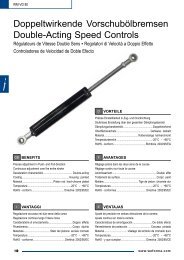
WV-M Vorschubölbremsen ▪ Speed C
- Page 102 and 103:
WV-M 1,25 Vorschubölbremsen ▪ Sp
- Page 104 and 105:
WM-V Vorschubölbremsen ▪ Speed C
- Page 106 and 107:
WM-VD 32 Doppeltwirkende Vorschubö
- Page 108 and 109:
WM-VD 36 Doppeltwirkende Vorschubö
- Page 110 and 111:
WM-VD 80 Doppeltwirkende Vorschubö
- Page 112 and 113:
Bedienungshinweise D Bedienungshinw
- Page 114 and 115:
116 www.weforma.com
- Page 116 and 117:
Berechnung ▪ Selection A B J K 11
- Page 118 and 119:
LDS Funktionsprinzip ▪ Operating
- Page 120 and 121:
LDS Schwerlastdämpfer Heavy-Duty S
- Page 122 and 123:
LDS 32 120 90 120 124 øKolben øPi
- Page 124 and 125:
LDS 50 140 111 140 126 øKolben øP
- Page 126 and 127:
LDS 80 128 200 160 210 øKolben øP
- Page 128 and 129:
LDS 125 277,5 130 275 220 øKolben
- Page 130 and 131:
Zubehör ▪ Accessories LDS Näher
- Page 132 and 133:
LDS Schwenkbefestigung ▪ Clevis M
- Page 134 and 135:
LDS-DW Doppeltwirkende Schwerlastd
- Page 136 and 137:
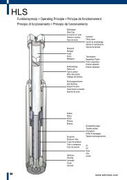
HLS Funktionsprinzip ▪ Operating
- Page 138 and 139:
HLS Schwerlastdämpfer Heavy-Duty S
- Page 140 and 141:
ø165 HLS 63 142 RFH ø18 ø135 RFV
- Page 142 and 143:
HLS 75 76 150 150 144 120 120 150 1
- Page 144 and 145:
HLS 100 ø255 * Ausführung mit Fal
- Page 146 and 147:
148 www.weforma.com
- Page 148 and 149:
Bedienungshinweise LDS / HLS D BEdI
- Page 150 and 151:
146 www.weforma.com
- Page 152 and 153:
Berechnung ▪ Selection A B C1 J 1
- Page 154 and 155:
Berechnung ▪ Selection ERLÄUTERU
- Page 156 and 157:
WES Funktionsprinzip ▪ Operating
- Page 158 and 159:
WES Elasto-Fluid Stoßdämpfer Elas
- Page 160 and 161:
WES 156 N H G ABMESSUNGEN ▪ DIMEN
- Page 162:
WES D5 158 D6 D3 WES mit Flansch: F
- Page 165 and 166:
D FUNKTIONSPRINzIP Elasto-Fluid Fed
- Page 167 and 168:
Kundenangaben - Information require
- Page 169 and 170:
Stoßdämpfer für Schrägaufzüge
- Page 171 and 172:
Zertifikat TÜV ▪ Certificate TÜ
- Page 173 and 174:
D FUNKTIONSPRINzIP SAD Schrägaufzu
- Page 175 and 176:
Hub Stroke Course Corsa Carrera A L
- Page 177 and 178:
Hub Stroke Course Corsa Carrera A L
- Page 179 and 180:
Aufzugsdämpfer Shock Absorbers for
- Page 181 and 182:
www.weforma.com 177 ADS
- Page 183 and 184:
D FUNKTIONSPRINzIP ADS Aufzugsdämp
- Page 185 and 186:
Hub Stroke Course Corsa Carrera ØD
- Page 187 and 188:
ØD Hub Stroke Course Corsa Carrera
- Page 189 and 190:
D FUNKTIONSPRINzIP ADS Aufzugsdämp
- Page 191 and 192:
ØD ABMESSUNGEN ▪ DIMENSIONS ▪
- Page 193 and 194:
ØD Ø60 B Hub Stroke Course Corsa
- Page 195 and 196:
Rotationsdämpfer Rotary Dampers Am
- Page 197 and 198:
M Rechtsdrehend Clockwise Sens hora
- Page 199 and 200:
WRD-H 7550 / 9565 / 12070 G D ØC I
- Page 201 and 202: Rechtsdrehend Clockwise Sens horair
- Page 203 and 204: M Rechtsdrehend Clockwise Sens hora
- Page 205 and 206: 8 11,5 WRD 22 11,5 8 8 11,5 WRD 23
- Page 207 and 208: WRD 58 Ritzel ▪ Standard spur gea
- Page 209 and 210: WRD 100 Ø16 10 7 10 4 31 50 15 12
- Page 211 and 212: M Rechtsdrehend Clockwise Sens hora
- Page 213 and 214: 8 11,5 WRD 22 11,5 8 8 11,5 WRD 23
- Page 215 and 216: WRD 58 Ritzel ▪ Standard spur gea
- Page 217 and 218: WRD 100 Ø16 10 7 10 4 31 50 15 12
- Page 219 and 220: Gasfedern Gas Springs Ressorts à G
- Page 221 and 222: Berechnung ▪ Selection Donneess d
- Page 223 and 224: Befestigung / Mounting Fixation / F
- Page 225 and 226: Befestigung / Mounting Fixation / F
- Page 227 and 228: 1 5 Befestigung / Mounting Fixation
- Page 229 and 230: M5 1-M5 5-M5 Kugelpfanne • Ball j
- Page 231 and 232: M10 1-M10 ø8,1 6-28-M10 17 10 25
- Page 233 and 234: Gasfeder-Füllkoffer ▪ Gas spring
- Page 235 and 236: D Typ 1 ▪ Blockierung in beide Ri
- Page 237 and 238: Typ 2 ▪ Type 2 Type 2 ▪ Tipo 2
- Page 239 and 240: Typ 4 ▪ Type 4 Type 4 ▪ Tipo 4
- Page 241 and 242: 2 HEBELAUSLÖSUNG ▪ RELEASE SySTE
- Page 243 and 244: Gewinde Thread Filetage Filettatura
- Page 245 and 246: 1 Gelenkauge • Male rod clevis T
- Page 247 and 248: Berechnung ▪ Selection A B 240 Hu
- Page 249 and 250: WBE Einfaltenbälge Single-Convolut
- Page 251: WBZ Zweifaltenbälge Double-Convolu
- Page 255 and 256: WBE / WBZ / WBD Luftfedern mit Alum
- Page 257 and 258: WBE-G / WBZ-G / WBD-G Luftfedern mi
- Page 259 and 260: WBE / WBZ / WBD Sonderlösungen ▪
- Page 261 and 262: ØD WBE-VA / WBZ-VA / WBD-VA Edelst
- Page 263 and 264: ECO Hochtemperaturausführung High-
- Page 265 and 266: ECO Luftfedern mit Gewindebolzen, H
- Page 267 and 268: WSR Schlauchrollbälge ▪ Rolling
- Page 269 and 270: WBL Luftfedern mit seitlichem Füll
- Page 271 and 272: 260 www.weforma.com
- Page 273 and 274: WEF Elastomerfedern ▪ Elastomer S
- Page 275 and 276: WCB Kranpuffer ▪ Crane Buffers Bu
- Page 277 and 278: WAP Aufsetzpuffer für Aufzüge Ove
- Page 280 and 281: Metallkissen Metal Cushions Coussin
- Page 282 and 283: D zur Berechnung der Metallkissen w
- Page 284 and 285: WG-RU Rundlager - Circular Type - T
- Page 286 and 287: WG-FL Flachlager - Rectangular Type
- Page 288 and 289: WG-AE Stabilisatoren - Stabilizers
- Page 290 and 291: Transfertechnik Components for Tran
- Page 292 and 293: WPS 310 / 320 / 500 Funktionsprinzi
- Page 294 and 295: D TECHNISCHE DATEN Druckbereich 4 -
- Page 296 and 297: Anschlag / Stop Plate Einstellung /
- Page 298 and 299: HB A HB ØF +0,03 E 20 13 B 20 13 3
- Page 300 and 301: HB A Sensor (optional) G Geschwindi
- Page 302 and 303:
174 16 18 HB 15 50 Geschwindigkeit
- Page 304 and 305:
WPR 20 59 WPR 22 82,5 Sensor (optio
- Page 306 and 307:
29 Ø11 Ø14 25 8,5 (13) G1/8 G1/8
- Page 308 and 309:
WPS 500 10 6 8 9 4 5 WPS-F 250 7 7
- Page 310 and 311:
14 WPR 22 13 WPz 32 / 40 15 3 4 16
- Page 312 and 313:
WVE 12-15 20 Hub Stroke Course Cors
- Page 314 and 315:
WGK 15 WGK 20 WGK 15 / 20 Sensor au
- Page 316 and 317:
1. Miscellaneous / Applicability (1
- Page 319:
Deutschland Weforma Dämpfungstechn