Fan coil Aermec FCS AS, P-PO, U Installation manual
Fan coil Aermec FCS AS, P-PO, U Installation manual
Fan coil Aermec FCS AS, P-PO, U Installation manual

You also want an ePaper? Increase the reach of your titles
YUMPU automatically turns print PDFs into web optimized ePapers that Google loves.
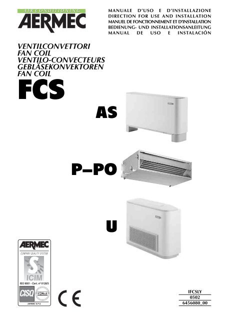
VENTILCONVETTORI<br />
FAN COIL<br />
VENTILO-CONVECTEURS<br />
GEBLÄSEKONVEKTOREN<br />
FAN COIL<br />
<strong>FCS</strong> <strong>AS</strong><br />
ISO 9001 - Cert. nº 0128/3<br />
AERMEC S.P.A.<br />
C E R T I F I E D<br />
Q U A L I T Y S Y S T E M<br />
P-<strong>PO</strong><br />
MANUALE D’USO E D’INSTALLAZIONE<br />
DIRECTION FOR USE AND INSTALLATION<br />
MANUEL DE FONCTIONNEMENT ET D’INSTALLATION<br />
BEDIENUNG- UND INSTALLATIONSANLEITUNG<br />
MANUAL DE USO E INSTALACIÓN<br />
U<br />
I<strong>FCS</strong>LY<br />
0502<br />
6456080_00
AERMEC S.p.A.<br />
I-37040 Bevilacqua (VR) Italia – Via Roma, 44<br />
Tel. (+39) 0442 633111<br />
Telefax (+39) 0442 93730 – (+39) 0442 93566<br />
www .aermec. com - info @aermec. com<br />
<strong>FCS</strong><br />
<strong>AS</strong><br />
P - <strong>PO</strong><br />
U<br />
DICHIARAZIONE DI CONFORMITÀ<br />
Noi, firmatari della presente, dichiariamo sotto la nostra esclusiva responsabilità, che la macchina in oggetto è conforme a<br />
quanto prescritto dalle seguenti Direttive:<br />
- Direttiva macchine 98/37 CEE;<br />
- Direttiva bassa tensione 73/23 CEE;<br />
- Direttiva compatibilità elettromagnetica EMC 89/36 CEE.<br />
DECLARATION OF CONFORMITY<br />
We declare under our own responsability that the above equipment complies with provisions of the following Standards:<br />
- Equipment Standard 98/37 EEC;<br />
- Low voltage Standard 73/23 EEC;<br />
- Electromagnetic compatibility Standard EMC 89/36 EEC.<br />
CERTIFICAT DE CONFORMITE<br />
Nous, signataires de la présente, certifions sous notre propre responsabilité, que l’appareil en objet est conforme aux suivantes<br />
Directives:<br />
- Directive appareil 98/37 EEC;<br />
- Directive basse tension 73/23 EEC;<br />
- Direttiva compatibilità elettromagnetica EMC 89/36 EEC.<br />
KONFORMITÄTSERKLÄRUNG<br />
Wir, Unterzeichner dieser Bescheinigung, bestätigen, daß diese Geräte den Vorschriften:<br />
- Vorschrift Geräte 98/37 EWG;<br />
- Niederspannung - Vorschrift 73/23 EWG;<br />
- Funkentstörung - Vorschrift EMC 89/36 EWG.<br />
DECLARACION DE CONFORMIDAD<br />
Declaramos bajo nuestra responsabilidad que los equipos arriba indicados cumplen con las siguientes directivas:<br />
- Directiva de máquinas 98/37;<br />
- Baja tensión 73/23 CEE;<br />
- Compatibilidad electromagnética (CEM) 89/36 CEE.<br />
Bevilacqua, 1/1/2005 La Direzione Commerciale - Sales and Marketing Director<br />
LUIGI ZUCCHI
INDICE CONTENTS INDEX INHALTSVERZEICHN ÍNDICE<br />
INFORMAZIONI GENERALI • GENERAL INFORMATION<br />
INFORMATIONS GENERALES ALLGEMEINE INFORMATIONEN INFORMACION GENERAL 2<br />
USI IMPROPRI IMPROPER USES ENTRETIEN<br />
UNSACHGEMÄßER GEBRAUCH USOS INCORRECTOS 2<br />
CARATTERISTICHE FEATURES CARACTERISTIQUES EIGENSCHAFTEN CARACTERISTIC<strong>AS</strong><br />
Dati dimensionali Dimensions Dimensions Abmessungen Dimensiones 4<br />
Schemi elettrici Wiring diagrams Schemas eléctriques Schaltplane Esquemas eléctricos 8<br />
INSTALLAZIONE INSTALLATION INSTALACION<br />
Imballo Installazione dell’unità Collegamenti elettrici 14<br />
Rotazione batteria 15<br />
Informazioni importanti e manutenzione 16<br />
Packing Unit installation Electrical connections 17<br />
Rotating the <strong>coil</strong> 18<br />
Important maintenance information 19<br />
Emballage <strong>Installation</strong> de l’unité Raccordements electriques 20<br />
Rotation de la batterie 21<br />
Information importantes sur la maintenance 22<br />
Verpackung <strong>Installation</strong> des Gerätes Elektrische anschlüsse 23<br />
Idrehen der batterie 24<br />
Wichtige hinweise und Wartung 25<br />
Embalaje Installación de la unidad Cconexiones eléctricas 26<br />
Rotación de la batería 27<br />
Informazioni importanti e mantenimiento 28<br />
MISURE DI SICUREZZA SAFETY ME<strong>AS</strong>URES MISURES DE SECURITE SICHEREITSMAßNAHMEN<br />
Trasporto Carriage Transport Transport Transporte<br />
Simboli di sicurezza Safety symbol Simboles de securite Sicherheitssymbole símbolos de seguridad 31<br />
USI IMPROPRI IMPROPER USES USAGES IMPROPRES UNSACHGEMÄßER GEBRAUCH USOS INCORRECTOS<br />
PERICOLO: Togliere tensione prima d’iniziare le operazioni di pulizia del filtro e/o dell’unità.<br />
DANGER: Switch off power supply before cleaning filter and/or unit.<br />
DANGER: Couper la tension avant de commencer les opérations de nettoyage du filtre et/ou de l'unité.<br />
GEFAHR: Vor der Reinigung des Filters und/oder des Gerätes die Stromversorgung abschalten.<br />
PELIGRO: Desconecte la corriente eléctrica antes de comenzar a limpiar el filtro o el equipo..<br />
GUERRA E PACE<br />
<strong>AS</strong>S<strong>AS</strong>SINIO SUL<br />
L'ORIENT EXPRESS<br />
20.000 LEGHE<br />
SOTTO I MARI<br />
3
DATI DIMENSIONALI DIMENSIONS DIMENSIONS ABMESSUNGEN DIMENSIONES [mm]<br />
<strong>FCS</strong> - <strong>AS</strong><br />
<strong>FCS</strong> - U<br />
A<br />
4<br />
B<br />
A<br />
D<br />
Mod. <strong>FCS</strong> 22 <strong>FCS</strong> 32 <strong>FCS</strong> 42 <strong>FCS</strong> 50 <strong>FCS</strong> 62 <strong>FCS</strong> 82<br />
A 563 563 563 563 688 688<br />
B 750 980 1200 1200 1320 1320<br />
C<br />
Peso<br />
Weight<br />
105 105 105 105 125 125<br />
Poids<br />
Gewicht<br />
Peso<br />
kg 15 20 24 24 34 34<br />
C<br />
B<br />
Peso ventilconvettore senza zoccoli Weight of fan <strong>coil</strong> without feet<br />
Poids ventilo-convecteur sans pieds Gewicht Gebläsekonvektor ohne Sockel Peso del fan <strong>coil</strong> sin zócalos<br />
Mod. 22 - 32 - 42 - 50 Mod. 62 - 82<br />
Mod. <strong>FCS</strong> 22 <strong>FCS</strong> 32 <strong>FCS</strong> 42 <strong>FCS</strong> 50 <strong>FCS</strong> 62 <strong>FCS</strong> 82<br />
A 520 520 520 520 590 590<br />
B<br />
Peso<br />
750 980 1200 1200 1320 1320<br />
Weight<br />
Poids<br />
kg<br />
Gewicht<br />
Peso<br />
15 20 24 24 34 34<br />
A<br />
C<br />
50<br />
100<br />
100<br />
50<br />
B C
DATI DIMENSIONALI DIMENSIONS DIMENSIONS ABMESSUNGEN DIMENSIONES [mm]<br />
9 x 20<br />
197<br />
248<br />
<strong>FCS</strong> 22 - 32 - 42 - 50<br />
25<br />
388<br />
9 x 20<br />
110<br />
350<br />
50<br />
<strong>FCS</strong> 62 - 82<br />
A (<strong>FCS</strong> P)<br />
B<br />
30 30<br />
C 50<br />
C<br />
A (<strong>FCS</strong>-P)<br />
B<br />
14 14<br />
216<br />
41 101<br />
3 R 3 R + 1 R<br />
216<br />
41 107<br />
49<br />
144<br />
453<br />
32<br />
253<br />
558<br />
216<br />
96 60<br />
3 R 3 R + 1 R<br />
Mod. <strong>FCS</strong> 22 <strong>FCS</strong> 32 <strong>FCS</strong> 42 <strong>FCS</strong> 50 <strong>FCS</strong> 62 <strong>FCS</strong> 82<br />
A (<strong>FCS</strong>-P) 562 793 1013 1013 1147 1147<br />
B 522 753 973 973 1122 1122<br />
C<br />
Peso<br />
Weight<br />
440 671 891 891 1102 1102<br />
Poids kg<br />
Gewicht<br />
Peso<br />
<strong>FCS</strong> P 13 18 22 22 33 33<br />
Attacchi batteria (femmina) Coil connection (female)<br />
Raccords batterie (femelle) Anschlüsse des Warmetäuschers (Innengewinde)<br />
Conexiones de la batería (hembra)<br />
Mod. <strong>FCS</strong> 22 <strong>FCS</strong> 32 <strong>FCS</strong> 42 <strong>FCS</strong> 50 <strong>FCS</strong> 62 <strong>FCS</strong> 82<br />
3 R 1/2” 1/2” 1/2” 1/2” 3/4” 3/4”<br />
1 R 1/2” 1/2” 1/2” 1/2” 1/2” 1/2”<br />
216<br />
96 60<br />
45<br />
85<br />
39<br />
141<br />
453<br />
558<br />
5
DATI DIMENSIONALI DIMENSIONS DIMENSIONS ABMESSUNGEN DIMENSIONES [mm]<br />
6<br />
100<br />
min.<br />
Installazione con supporti AMP (accessori) <strong>Installation</strong> with AMP brackets (accessories)<br />
<strong>Installation</strong> avec supports AMP (accessories) <strong>Installation</strong> mit AMP halterung (zubehöre)<br />
Instalación con soportes AMP (accesorios)<br />
<strong>FCS</strong> - U 22 - 32 - 42 - 50 <strong>FCS</strong> - U 62 - 82<br />
48 258 117 258<br />
<strong>FCS</strong> - P - <strong>PO</strong> 22 - 32 - 42 - 50<br />
36 258 105 258<br />
100<br />
min.<br />
5 5<br />
<strong>FCS</strong> <strong>AS</strong> - U - P<br />
A<br />
D C<br />
E<br />
F<br />
B<br />
<strong>FCS</strong> - P - <strong>PO</strong> 62 - 82<br />
Mod. <strong>FCS</strong> 22 <strong>FCS</strong> 32 <strong>FCS</strong> 42 <strong>FCS</strong> 50 <strong>FCS</strong> 62 <strong>FCS</strong> 82<br />
A 750 981 1201 1201 1322 1322<br />
B 555 786 1006 1006 1127 1127<br />
C 600 831 1051 1051 1172 1172<br />
D 95,5 95,5 95,5 95,5 95,5 95,5<br />
E 54,5 54,5 54,5 54,5 54,5 54,5<br />
F 144,5 144,5 144,5 144,5 144,5 144,5<br />
G 103,5 103,5 103,5 103,5 103,5 103,5<br />
G<br />
24x9<br />
In caso di inversione degli attacchi idraulici, scambiare tra loro le seguenti quote: D con E, F con G.<br />
In case of inversion hydraulic connections, invert D with E, F with G.<br />
En cas d’inversion des raccords hydrauliques, inverser les cotes D avec E, F avec G.<br />
Bei der Anschlüßenumstellung, die Quoten D und E, F und G, miteinander auswechseln.<br />
Si desea invertir el lado de las conexiones hidráulicas, intercambie D por E y F por G.
DATI DIMENSIONALI DIMENSIONS DIMENSIONS ABMESSUNGEN DIMENSIONES [mm]<br />
<strong>FCS</strong> 22 ÷ 50 3R <strong>FCS</strong> 62 ÷ 82 3R<br />
404<br />
88<br />
408<br />
260<br />
153<br />
41<br />
142<br />
96<br />
194<br />
<strong>FCS</strong> 22 ÷ 50 1R <strong>FCS</strong> 62 ÷ 82 1R<br />
88<br />
323<br />
153<br />
155<br />
194<br />
526<br />
108<br />
519<br />
108<br />
273<br />
378<br />
170<br />
170<br />
41<br />
148<br />
96<br />
194<br />
156<br />
194<br />
7
SCHEMI ELETTRICI WIRING DIAGRAMS SCHEM<strong>AS</strong> ELECTRIQUES SCHALTPLÄNE ESQUEM<strong>AS</strong> ELÉCTRICOS<br />
LEGENDA READING KEY LEGENDE LEGENDE LEYENDA<br />
CRE =Contattore resistenza elettrica Electric heater contactor<br />
Contacteur résistance eléctrique El. Heizregister-Schutz<br />
Contactor de la resistencia eléctrica<br />
F =Fusibile Fuse Fusible Sicherung Fusible<br />
IG =Interruttore generale Main switch<br />
Interupteur général Hauptschalter<br />
Interruptor general<br />
M =Morsettiera Terminal board<br />
Boitier Klemmleiste Placa de bornes<br />
MS =Microinterruttore griglia Louvre microswitch<br />
Micro-interrupteur grille Mikroschalter Gitter<br />
Microinterruptor de la rejilla de impulsión<br />
MV =Motore ventilatore <strong>Fan</strong> motor Moteur ventilateur<br />
Ventilatormotor Motor del ventilador<br />
RX =Resistenza elettrica Electric heater<br />
SA<br />
Résistance électrique Elt. Heizregister<br />
Resistencia eléctrica<br />
=Sonda ambiente Room sensor Sonde ambiante<br />
Raumtemperaturfuhler Sonda ambiente<br />
SC =Scheda di controllo Electronic control board<br />
Platine de contrôle Steuerschaltkreis<br />
Tarjeta electrónica de control<br />
SW =Sonda minima temperatura acqua<br />
Water low temperature sensor<br />
Sonde minimum temp. eau<br />
Wasserfühler<br />
Sonda temperatura mínima del agua<br />
TR =Trasformatore Transformer Transformateur<br />
Transformator Transformador<br />
TSR =Termostato a riarmo automatico<br />
Automatic resetting thermostat<br />
Thermostat à réarmement automatique<br />
Thermostat automatischer Entriegelung<br />
Termostato de rearme automático<br />
8<br />
COMUNE - BL<br />
BI<br />
L 1 2 3 4 5 6 7<br />
NE<br />
MAX. VEL. - NE<br />
GR<br />
MED. VEL. - MA<br />
MIN. VEL. - RO<br />
TSRM = Termostato a riarmo <strong>manual</strong>e<br />
Manual resetting thermostat<br />
Thermostat à réarmement manuel<br />
Thermostat manueller Entriegelung<br />
Termostato de rearme <strong>manual</strong><br />
VCF = Valvola solenoide Solenoid valve<br />
Vanne solenoide Magnetventil Válvula solenoide<br />
VC = Valvola solenoide caldo Solenoid valve hot<br />
Vanne magnétique chaud Magnetventil Heizbetrieb<br />
Válvula solenoide para calor<br />
VF = Valvola solenoide freddo Solenoid valve cold<br />
Vanne magnétique froid Magnetventil Kühlbetrieb<br />
Válvula solenoide para frío<br />
= Componenti non forniti Components not supplied<br />
Composants non fournis Nicht lieferbare Teile<br />
Componentes no suministrados<br />
= Componenti forniti optional Optional components<br />
Composants en option Optionsteile<br />
Componentes opcionales<br />
=Collegamenti da eseguire in loco On-site wiring<br />
Raccordements à effectuer in situ<br />
Vor Ort auszuführende Anschlüsse Cableado in situ<br />
AR = Arancio Orange Orange Orange Naranja<br />
BI = Bianco White Blanc Weiss Blanco<br />
BL = Blu Blue Bleu Blau Azul<br />
GR = Grigio Grey Gris Gray Gris<br />
MA = Marrone Brown Marron Braun Marrón<br />
NE = Nero Black Noir Schwarz Negro<br />
RO = Rosso Red Rouge Rot Rojo<br />
VE = Verde Green Vert Grün Verde<br />
VI = Viola Violet Violet Violet Violeta<br />
SCHEMA DI COLLEGAMENTO MOTORE <strong>FCS</strong> - <strong>PO</strong> <strong>FCS</strong> - <strong>PO</strong> MOTOR CONNECTION DIAGRAM<br />
SCHEMA DE RACCORDEMENT MOTEUR <strong>FCS</strong> - <strong>PO</strong> ANSCHLUSSPLAN MOTOR <strong>FCS</strong> - <strong>PO</strong><br />
ESQUEMA DE CONEXIONADO ELÉCTRICO DEL MOTOR <strong>FCS</strong> - <strong>PO</strong><br />
GI<br />
BL<br />
Le velocità disponibili sono numerate da 1 a 7 in ordine decrescente di velocità<br />
Available speeds are numbered from 1 to 7 following a speed decreasing order<br />
Les vitesses disponibles sont numeratées de 1 à 7 en ordre de vitesse décroissante<br />
Die verfügbaren Drehzahlen sind von 1 zu 7 mit abnehmender Drehzahlstufe numeriert<br />
Las velocidades disponibles se numeran, en orden decreciente, de 1 a 7.<br />
VE<br />
MA<br />
AR<br />
RO
<strong>FCS</strong> - <strong>AS</strong><br />
<strong>FCS</strong> - P<br />
<strong>FCS</strong> - U (solo 62 - 82) Universale senza comandi<br />
(62 - 82 only) Universal, without controls<br />
(seulement 62 - 82 ) Universel sans commandes<br />
(nur 62 - 82) Universalgerät ohne Steuerungen<br />
(sólo 62 - 82) Universal sin panel de mandos<br />
M<br />
1 2 3 4 5 6 7 8 9 10<br />
Sez. 1,5 mm 2<br />
IG 2A L N<br />
230V 50Hz<br />
PTI termostato elettronico<br />
electronic thermostat<br />
thermostat électronique<br />
elektronischer Thermostat<br />
termostato electrónico<br />
SA<br />
SA<br />
PTI<br />
V1<br />
V2<br />
V3<br />
Y1<br />
L<br />
PE<br />
N<br />
SW<br />
VCF<br />
M<br />
MAX<br />
MED<br />
BL NE MA RO<br />
MV<br />
~1<br />
BI AR AR<br />
MIN<br />
PE<br />
1 2 3 4 5 6 7 8 9 10<br />
SW<br />
GR<br />
Sez. 1,5 mm 2<br />
IG 2A L N<br />
230V 50Hz<br />
BL NE MA RO<br />
MAX<br />
MED<br />
MIN<br />
BL NE MA RO<br />
MV<br />
~1<br />
PE<br />
<strong>FCS</strong> - U (escluso 62 - 82) Universale senza comandi<br />
(except 62 - 82) Universal, without controls<br />
(esclus 62 - 82) Universel sans commandes<br />
(ohne 62 - 82) Universalgerät ohne<br />
Steuerungen<br />
(excluidos 62 - 82) Universal sin panel de<br />
mandos<br />
M<br />
1 2 3<br />
4<br />
GR<br />
Sez. 1,5 mm 2<br />
M<br />
IG 2A L N<br />
230V 50Hz<br />
MS<br />
1 2 3 4 5 6 7 8 9 10<br />
BL NE MA RO<br />
6 7 8<br />
9 10<br />
MAX<br />
MED<br />
MIN<br />
BL NE MA RO<br />
MV<br />
~1<br />
Sez. 1,5 mm 2<br />
IG 2A L N<br />
230V 50Hz<br />
PE<br />
ML<br />
NE<br />
12345<br />
MAX<br />
MED<br />
BL NE MA RO<br />
BI<br />
BL<br />
GI<br />
RO<br />
SW<br />
MV<br />
~1<br />
PXLM termostato elettronico ed alette motorizzate<br />
con <strong>FCS</strong> - U (escluso 62 - 82)<br />
electronic thermostat and motorized fins<br />
with <strong>FCS</strong> - U (62 - 82 excluded)<br />
thermostat électronique et ailettes motorisees<br />
avec <strong>FCS</strong> - U (esclus 62 - 82)<br />
elektronischer Thermostat mit Motorbetriebenen Lamellen<br />
mit <strong>FCS</strong> - U (ohne 62 - 82)<br />
termostato electrónico y lamas motorizadas<br />
con <strong>FCS</strong> - U (excluidos 62 - 82)<br />
AL<br />
M2 12Vdc GND<br />
M1 230 0<br />
5<br />
EX<br />
MIN<br />
V1<br />
V2<br />
V3<br />
L<br />
N<br />
1<br />
2<br />
3<br />
4<br />
5<br />
M2<br />
EX<br />
EX<br />
M3<br />
12V<br />
GND<br />
SA<br />
SA<br />
SW<br />
SW<br />
M1<br />
CN1<br />
M4<br />
SA<br />
PE<br />
9<br />
PXL4
PXB termostato elettronico a funzioni ridotte<br />
con <strong>FCS</strong> - U (solo 62 - 82) / <strong>FCS</strong> - <strong>AS</strong> / P<br />
reduced-function electronic thermostat<br />
with <strong>FCS</strong> - U (62 - 82 only) / <strong>FCS</strong> - <strong>AS</strong> / P<br />
thermostat électronique à fonctions réduites<br />
avec <strong>FCS</strong> - U (seulement 62 - 82) / <strong>FCS</strong> - <strong>AS</strong><br />
elektronischer Thermostat mit eingeschränkten Funktionen<br />
mit <strong>FCS</strong> - U (nur 62 - 82) / <strong>FCS</strong> - <strong>AS</strong> / P<br />
termostato electrónico de funciones reducidas<br />
con <strong>FCS</strong> - U (sólo 62 - 82) / <strong>FCS</strong> - <strong>AS</strong> / P<br />
VCF<br />
M<br />
M<br />
1 2 3 4 5 6 7 8 9 10<br />
10<br />
GR<br />
Sez. 1,5 mm 2<br />
GR<br />
1 2 3 4 5 6 7 8 9 10<br />
Sez. 1,5 mm 2<br />
IG 2A L N<br />
230V 50Hz<br />
PX2 commutatore a distanza<br />
con <strong>FCS</strong> - U (solo 62 - 82) / <strong>FCS</strong> - <strong>AS</strong> / P<br />
remote switch<br />
with <strong>FCS</strong> - U (62 - 82 only) / <strong>FCS</strong> - <strong>AS</strong> / P<br />
commutateur à distance<br />
avec <strong>FCS</strong> - U (seulement 62 - 82) / <strong>FCS</strong> - <strong>AS</strong> / P<br />
Fernumschalter<br />
mit <strong>FCS</strong> - U (nur 62 - 82) / <strong>FCS</strong> - <strong>AS</strong> / P<br />
conmutador remoto<br />
con <strong>FCS</strong> - U (sólo 62 - 82) / <strong>FCS</strong> - <strong>AS</strong> / P<br />
IG 2A L N<br />
230V 50Hz<br />
BL NE MA RO<br />
MAX<br />
MED<br />
MIN<br />
BL NE MA RO<br />
MV<br />
~1<br />
NE MA RO<br />
MAX<br />
MED<br />
MIN<br />
BL NE MA RO<br />
MV<br />
~1<br />
PE<br />
PE<br />
N<br />
N<br />
PE<br />
L<br />
Y1<br />
V3<br />
V2<br />
V1<br />
M1<br />
M2<br />
1<br />
2<br />
3<br />
4<br />
5<br />
6<br />
PT1<br />
EXT INT<br />
DL1<br />
JP1<br />
SA<br />
PXB<br />
PX2<br />
PXB termostato elettronico a funzioni ridotte<br />
con <strong>FCS</strong> - U (escluso 62 - 82)<br />
reduced-function electronic thermostat<br />
with <strong>FCS</strong> - U (62 - 82 excluded)<br />
thermostat électronique à fonctions réduites<br />
avec <strong>FCS</strong> - U (esclus 62 - 82)<br />
elektronischer Thermostat mit eingeschränkten Funktionen<br />
mit <strong>FCS</strong> - U (ohne 62 - 82)<br />
termostato electrónico de funciones reducidas<br />
con <strong>FCS</strong> - U (excluidos 62 - 82)<br />
VCF<br />
M<br />
PX2 commutatore a distanza<br />
con <strong>FCS</strong> - U (escluso 62 - 82)<br />
remote switch<br />
with <strong>FCS</strong> - U (62 - 82 excluded)<br />
commutateur à distance<br />
avec <strong>FCS</strong> - U (esclus 62 - 82)<br />
Fernumschalter<br />
mit <strong>FCS</strong> - U (ohne 62 - 82)<br />
conmutador remoto<br />
con <strong>FCS</strong> - U (excluidos 62 - 82)<br />
M<br />
MS<br />
1 2 3 4 5 6 7 8 9 10<br />
Sez. 1,5 mm 2<br />
IG 2A L N<br />
230V 50Hz<br />
MS<br />
GR<br />
1 2 3 4 5 6 7 8 9 10<br />
Sez. 1,5 mm 2<br />
GR<br />
IG 2A L N<br />
230V 50Hz<br />
BL NE MA RO<br />
MAX<br />
MED<br />
MIN<br />
BL NE MA RO<br />
MV<br />
~1<br />
NE MA RO<br />
MAX<br />
MED<br />
MIN<br />
BL NE MA RO<br />
MV<br />
~1<br />
PE<br />
PE<br />
N<br />
N<br />
PE<br />
L<br />
Y1<br />
V3<br />
V2<br />
V1<br />
M1<br />
M2<br />
1<br />
2<br />
3<br />
4<br />
5<br />
6<br />
PT1<br />
EXT INT<br />
DL1<br />
JP1<br />
SA<br />
PXB<br />
PX2
PXL2E termostato elettronico a distanza<br />
con <strong>FCS</strong> - U (solo 62 - 82) / <strong>FCS</strong> - <strong>AS</strong> / P<br />
remote electronic thermostat<br />
with <strong>FCS</strong> - U (62 - 82 only) / <strong>FCS</strong> - <strong>AS</strong> / P<br />
thermostat électronique<br />
avec <strong>FCS</strong> - U (seulement 62 - 82) / <strong>FCS</strong> - <strong>AS</strong> / P<br />
elektronischem Fernsteuerungsthermostat<br />
mit <strong>FCS</strong> - U (nur 62 - 82) / <strong>FCS</strong> - <strong>AS</strong> / P<br />
termostato electrónico<br />
con <strong>FCS</strong> - U (sólo 62 - 82) / <strong>FCS</strong> - <strong>AS</strong> / P<br />
VCF<br />
M<br />
GR<br />
1 2 3 4 5 6 7 8 9 10<br />
Sez. 1,5 mm 2<br />
IG 2A L N<br />
230V 50Hz<br />
BL NE MA RO<br />
MAX<br />
MED<br />
MIN<br />
BL NE MA RO<br />
MV<br />
~1<br />
PE<br />
SW<br />
EX<br />
N<br />
N<br />
N<br />
PE<br />
L<br />
Y1<br />
V3<br />
V2<br />
V1<br />
M<br />
EX<br />
PXL2I termostato elettronico<br />
con <strong>FCS</strong> - U (solo 62 - 82) / <strong>FCS</strong> - <strong>AS</strong><br />
electronic thermostat<br />
with <strong>FCS</strong> - U (only 62 - 82) / <strong>FCS</strong> - <strong>AS</strong><br />
thermostat électronique<br />
avec <strong>FCS</strong> - U (seulement 62 - 82) / <strong>FCS</strong> - <strong>AS</strong><br />
elektronischer Thermostat<br />
mit <strong>FCS</strong> - U (nur 62 - 82) / <strong>FCS</strong> - <strong>AS</strong><br />
termostato electrónico<br />
con <strong>FCS</strong> - U (sólo 62 - 82) / <strong>FCS</strong> - <strong>AS</strong><br />
VCF<br />
M<br />
GR<br />
1 2 3 4 5 6 7 8 9 10<br />
Sez. 1,5 mm 2<br />
IG 2A L N<br />
230V 50Hz<br />
BL NE MA RO<br />
MAX<br />
MED<br />
MIN<br />
BL NE MA RO<br />
MV<br />
~1<br />
SA<br />
PE<br />
SW<br />
EX<br />
M<br />
SA<br />
M<br />
SW<br />
N<br />
N<br />
N<br />
PE<br />
L<br />
Y1<br />
V3<br />
V2<br />
V1<br />
M<br />
EX<br />
M<br />
SA<br />
M<br />
SW<br />
SA<br />
PXL2E<br />
PXL2I<br />
PXL2E termostato elettronico a distanza<br />
con <strong>FCS</strong> - U (escluso 62 - 82)<br />
remote electronic thermostat<br />
with <strong>FCS</strong> - U (62 - 82 excluded)<br />
thermostat électronique<br />
avec <strong>FCS</strong> - U (esclus 62 - 82)<br />
elektronischem Fernsteuerungsthermostat<br />
mit <strong>FCS</strong> - U (62 - 82 ohne)<br />
termostato electrónico<br />
con <strong>FCS</strong> - U (excluidos 62 - 82)<br />
VCF<br />
M<br />
VCF<br />
M<br />
MS<br />
GR<br />
1 2 3 4 5 6 7 8 9 10<br />
Sez. 1,5 mm 2<br />
IG 2A L N<br />
230V 50Hz<br />
MS<br />
GR<br />
BL NE MA RO<br />
MAX<br />
MED<br />
MIN<br />
BL NE MA RO<br />
MV<br />
~1<br />
PXL2I termostato elettronico<br />
con <strong>FCS</strong> - U (escluso 62 - 82)<br />
electronic thermostat<br />
with <strong>FCS</strong> - U (62 - 82 excluded)<br />
thermostat électronique<br />
avec <strong>FCS</strong> - U (esclus 62 - 82)<br />
elektronischer Thermostat<br />
mit <strong>FCS</strong> - U (ohne 62 - 82)<br />
termostato electrónico<br />
con <strong>FCS</strong> - U (excluidos 62 - 82)<br />
1 2 3 4 5 6 7 8 9 10<br />
Sez. 1,5 mm 2<br />
IG 2A L N<br />
230V 50Hz<br />
BL NE MA RO<br />
MAX<br />
MED<br />
MIN<br />
BL NE MA RO<br />
MV<br />
~1<br />
PE<br />
SA<br />
PE<br />
SW<br />
SW<br />
EX<br />
EX<br />
N<br />
N<br />
N<br />
PE<br />
L<br />
Y1<br />
V3<br />
V2<br />
V1<br />
M<br />
EX<br />
M<br />
SA<br />
M<br />
SW<br />
N<br />
N<br />
N<br />
PE<br />
L<br />
Y1<br />
V3<br />
V2<br />
V1<br />
M<br />
EX<br />
M<br />
SA<br />
M<br />
SW<br />
SA<br />
PXL2E<br />
PXL2I<br />
11
PXL4 con pannello comandi per controllo valvole con <strong>FCS</strong> - U (solo 62 - 82) / <strong>FCS</strong> - <strong>AS</strong> / <strong>FCS</strong> - P<br />
control panel for valves with <strong>FCS</strong> - U (62 - 82 only) / <strong>FCS</strong> - <strong>AS</strong> / <strong>FCS</strong> - P<br />
panneau de commande pour contrôle vannes avec <strong>FCS</strong> - U (seulement 62 - 82) / <strong>FCS</strong> - <strong>AS</strong> / <strong>FCS</strong> - P<br />
Fernbedienung zur Steuerung von Ventilen mit <strong>FCS</strong> - U (nur 62 - 82) / <strong>FCS</strong> - <strong>AS</strong> / <strong>FCS</strong> - P<br />
panel de mandos para válvulas con <strong>FCS</strong> - U (sólo 62 - 82) / <strong>FCS</strong> - <strong>AS</strong> / <strong>FCS</strong> - P<br />
4 tubi pannello PXL 4 a bordo macchina<br />
4 tube PXL 4 panel on board machine<br />
4 tuyaux panneau PXL 4 sur l'appareil<br />
4 Röhren Platte PXL 4 am Gerät<br />
4 tubos panel PXL 4 en el equipo<br />
VC<br />
RX<br />
M<br />
BI<br />
TSR<br />
CRE<br />
IG L N<br />
230V 50Hz<br />
12<br />
1 2 3 4 5 6 7 8 9 10<br />
VF<br />
VI<br />
VF<br />
M<br />
BI<br />
VI<br />
GR<br />
1 2 3 4 5<br />
RE<br />
TSRM<br />
GR<br />
Sez. 1,5 mm 2<br />
IG 2A L N<br />
230V 50Hz<br />
BL NE MA RO<br />
Sez. 1,5 mm 2<br />
MAX<br />
MED<br />
MIN<br />
BL NE MA RO<br />
MV<br />
~1<br />
2 tubi con resistenza RX pannello PXL 4 a bordo macchina<br />
2 tubes with RX resistance PXL 4 panel on board machine<br />
2 tuyaux avec résistance RX panneau PXL 4 sur l'appareil<br />
2 Röhren mit Widerstand RX Platte PXL 4 am Gerät<br />
2 tubos con resistencia RX panel PXL 4 en el equipo<br />
IG 2A L N<br />
230V 50Hz<br />
BL NE MA RO<br />
6 7 8<br />
9 10<br />
MAX<br />
MED<br />
MIN<br />
BL NE MA RO<br />
MV<br />
~1<br />
SA<br />
PE<br />
SW<br />
PE<br />
SA<br />
EX<br />
SW<br />
EX<br />
N<br />
N<br />
N<br />
PE<br />
L<br />
Y2<br />
Y1<br />
V3<br />
V2<br />
V1<br />
M<br />
EX<br />
M<br />
SA<br />
M<br />
SW<br />
N<br />
N<br />
N<br />
PE<br />
L<br />
Y2<br />
Y1<br />
V3<br />
V2<br />
V1<br />
M<br />
EX<br />
M<br />
SA<br />
M<br />
SW<br />
PXL4<br />
PXL4<br />
4 tubi pannello PXL 4 a muro<br />
4 tubes PXL 4 wall-mounted panel<br />
4 tuyaux panneau PXL 4 inst. murale<br />
4 Röhren Platte PXL 4 an Wand<br />
4 tubos panel PXL 4 mural<br />
VC<br />
M<br />
1 2 3 4 5 6 7 8 9 10<br />
2 tubi con resistenza RX pannello PXL 4 a muro<br />
2 tubes with RX resistance PXL 4 wall-mounted panel<br />
2 tuyaux avec résistance RX panneau PXL 4 inst. murale<br />
2 Röhren mit Widerstand RX Platte PXL 4 an Wand<br />
2 tubos con resistencia RX panel PXL 4 mural<br />
RX<br />
TSR<br />
CRE<br />
IG L N<br />
230V 50Hz<br />
Sez. 1,5 mm 2<br />
IG 2A L N<br />
230V 50Hz<br />
VF<br />
M<br />
BI<br />
VI<br />
GR<br />
1 2 3 4 5 6 7 8 9 10<br />
RE<br />
TSRM<br />
BL NE MA RO<br />
MAX<br />
MED<br />
MIN<br />
BL NE MA RO<br />
PXL4 pannello comandi per controllo valvola e resistenza elettrica con <strong>FCS</strong> - U (solo 62 - 82) / <strong>FCS</strong> - <strong>AS</strong> / <strong>FCS</strong> - P<br />
control panel for valve and electrical resistance control with <strong>FCS</strong> - U (62 - 82 only) / <strong>FCS</strong> - <strong>AS</strong> / <strong>FCS</strong> - P<br />
avec panneau de commande pour contrôle vanne et résistance avec <strong>FCS</strong> - U (seulement 62 - 82) / <strong>FCS</strong> - <strong>AS</strong> / <strong>FCS</strong> - P<br />
Fernbedienung zur Steuerung von Ventilen bzw. elektrischem Heizregister mit <strong>FCS</strong> - U (nur 62 - 82) / <strong>FCS</strong> - <strong>AS</strong> / <strong>FCS</strong> - P<br />
panel de mandos para válvula y resistencia eléctrica con <strong>FCS</strong> - U (sólo 62 - 82) / <strong>FCS</strong> - <strong>AS</strong> / <strong>FCS</strong> - P<br />
BI<br />
VF<br />
VI<br />
GR<br />
MV<br />
~1<br />
Sez. 1,5 mm 2<br />
IG 2A L N<br />
230V 50Hz<br />
PE<br />
BL NE MA RO<br />
MAX<br />
MED<br />
MIN<br />
BL NE MA RO<br />
MV<br />
~1<br />
SW<br />
PE<br />
SW<br />
EX<br />
EX<br />
N<br />
N<br />
N<br />
PE<br />
L<br />
Y2<br />
Y1<br />
V3<br />
V2<br />
V1<br />
M<br />
EX<br />
M<br />
SA<br />
M<br />
SW<br />
N<br />
N<br />
N<br />
PE<br />
L<br />
Y2<br />
Y1<br />
V3<br />
V2<br />
V1<br />
M<br />
EX<br />
M<br />
SA<br />
M<br />
SW<br />
SA<br />
SA<br />
PXL4<br />
PXL4
PXL4 con pannello comandi per controllo valvole con <strong>FCS</strong> - U (escluso 62 - 82)<br />
control panel for valves with <strong>FCS</strong> - U (62 - 82 excluded)<br />
panneau de commande pour contrôle vannes avec <strong>FCS</strong> - U (esclus 62 - 82)<br />
Fernbedienung zur Steuerung von Ventilen mit <strong>FCS</strong> - U (ohne 62 - 82)<br />
panel de mandos para válvulas con <strong>FCS</strong> - U (excluidos 62 - 82)<br />
4 tubi pannello PXL 4 a bordo macchina<br />
4 tube PXL 4 panel on board machine<br />
4 tuyaux panneau PXL 4 sur l'appareil<br />
4 Röhren Platte PXL 4 am Gerät<br />
4 tubos panel PXL 4 en el equipo<br />
RX<br />
VC<br />
M<br />
BI<br />
TSR<br />
CRE<br />
IG L N<br />
230V 50Hz<br />
1 2 3 4 5 6 7 8 9 10<br />
VF<br />
VF<br />
VI<br />
M<br />
BI<br />
VI<br />
1 2 3 4<br />
RE<br />
TSRM<br />
MS<br />
GR<br />
Sez. 1,5 mm 2<br />
IG 2A L N<br />
230V 50Hz<br />
MS<br />
GR<br />
Sez. 1,5 mm 2<br />
BL NE MA RO<br />
MAX<br />
MED<br />
MIN<br />
BL NE MA RO<br />
MV<br />
~1<br />
2 tubi con resistenza RX pannello PXL 4 a bordo macchina<br />
2 tubes with RX resistance PXL 4 panel on board machine<br />
2 tuyaux avec résistance RX panneau PXL 4 sur l'appareil<br />
2 Röhren mit Widerstand RX Platte PXL 4 am Gerät<br />
2 tubos con resistencia RX panel PXL 4 en el equipo<br />
5 6 7 8 9 10<br />
IG 2A L N<br />
230V 50Hz<br />
BL NE MA RO<br />
MAX<br />
MED<br />
MIN<br />
BL NE MA RO<br />
MV<br />
~1<br />
SA<br />
PE<br />
SA<br />
PE<br />
SW<br />
SW<br />
EX<br />
EX<br />
N<br />
N<br />
N<br />
PE<br />
L<br />
Y2<br />
Y1<br />
V3<br />
V2<br />
V1<br />
M<br />
EX<br />
M<br />
SA<br />
M<br />
SW<br />
N<br />
N<br />
N<br />
PE<br />
L<br />
Y2<br />
Y1<br />
V3<br />
V2<br />
V1<br />
M<br />
EX<br />
M<br />
SA<br />
M<br />
SW<br />
PXL4<br />
PXL4<br />
4 tubi pannello PXL 4 a muro<br />
4 tubes PXL 4 wall-mounted panel<br />
4 tuyaux panneau PXL 4 inst. murale<br />
4 Röhren Platte PXL 4 an Wand<br />
4 tubos panel PXL 4 mural<br />
2 tubi con resistenza RX pannello PXL 4 a muro<br />
2 tubes with RX resistance PXL 4 wall-mounted panel<br />
2 tuyaux avec résistance RX panneau PXL 4 inst. murale<br />
2 Röhren mit Widerstand RX Platte PXL 4 an Wand<br />
2 tubos con resistencia RX panel PXL 4 mural<br />
RX<br />
VC<br />
M<br />
TSR<br />
CRE<br />
IG L N<br />
230V 50Hz<br />
VF<br />
M<br />
BI<br />
VI<br />
MS<br />
1 2 3 4 5 6 7 8 9 10<br />
Sez. 1,5 mm 2<br />
RE<br />
TSRM<br />
MS<br />
1 2 3 4 5 6 7 8 9 10<br />
Sez. 1,5 mm 2<br />
IG 2A L N<br />
230V 50Hz<br />
GR<br />
IG 2A L N<br />
230V 50Hz<br />
BL NE MA RO<br />
MAX<br />
MED<br />
MIN<br />
BL NE MA RO<br />
PXL4 pannello comandi per controllo valvola e resistenza elettrica con <strong>FCS</strong> - U (escluso 62 - 82)<br />
control panel for valve and electrical resistance control with <strong>FCS</strong> - U (62 - 82 excluded)<br />
avec panneau de commande pour contrôle vanne et résistance avec <strong>FCS</strong> - U (esclus 62 - 82)<br />
Fernbedienung zur Steuerung von Ventilen bzw. elektrischem Heizregister mit <strong>FCS</strong> - U (ohne 62 - 82)<br />
panel de mandos para válvula y resistencia eléctrica con <strong>FCS</strong> - U (excluidos 62 - 82)<br />
BI<br />
VF<br />
VI<br />
GR<br />
MV<br />
~1<br />
BL NE MA RO<br />
MAX<br />
MED<br />
MIN<br />
BL NE MA RO<br />
MV<br />
~1<br />
PE<br />
SW<br />
PE<br />
SW<br />
EX<br />
EX<br />
N<br />
N<br />
N<br />
PE<br />
L<br />
Y2<br />
Y1<br />
V3<br />
V2<br />
V1<br />
M<br />
EX<br />
M<br />
SA<br />
M<br />
SW<br />
N<br />
N<br />
N<br />
PE<br />
L<br />
Y2<br />
Y1<br />
V3<br />
V2<br />
V1<br />
M<br />
EX<br />
M<br />
SA<br />
M<br />
SW<br />
SA<br />
SA<br />
PXL4<br />
PXL4<br />
13
PACKING<br />
The units are shipped in cardboard box standard packing<br />
and polystirene shells.<br />
UNIT INSTALLATION<br />
The fan<strong>coil</strong> should be installed in such a way as to facilitate<br />
routine (filter cleaning) and special maintenance operations,<br />
as well as access to the air breather valve on the side of the<br />
unit frame (connector side).<br />
To install the unit, proceed as follows:<br />
a)Extract the air filter (<strong>FCS</strong> - <strong>AS</strong> model only).<br />
b)Remove the housing by loosening the screws (Figures 1<br />
and 2), or the rear cover panel in the case of wall models,<br />
sizes 22 to 50.<br />
c)In the case of wall-mounted <strong>FCS</strong>-<strong>AS</strong> unit, keep a minimum<br />
clearance of 80 mm from the floor. In the case of<br />
floor-mounted units on bases, refer to the instructions supplied<br />
with the accessory.<br />
d)Use expansion plugs (not supplied) to secure the unit to<br />
the wall or ceiling, as shown in figures 5 and 6.<br />
To install hanging units with the AMP brackets, proceed<br />
as follows:<br />
- fit the 4 brackets (1 in Fig. 8) to the sides of the unit;<br />
insert the upper tab in the slot, then secure the lower part<br />
to the contact block by means of the screws supplied;<br />
- secure the flanges (2) to the ceiling by means of expansion<br />
plugs (not supplied); for the positions between the<br />
flanges and the contact block, see the dimensional data.<br />
e)Make hydraulic connections.<br />
Refer to the dimensional data for the position and diameter<br />
of the hydraulic connectors.<br />
Insulate water lines adequately or fit the condensate drainage<br />
tray (available as an accessory) to prevent dripping<br />
during cooling applications.<br />
In case of horizontal installation, fit the condensate<br />
discharge pipe (supplied separately) following the indications<br />
shown in picture 10. The connection between pipe<br />
and drip tray must be sealed with silicone.<br />
The condensate drainage system should be of an adequate<br />
size and be positioned to favour runoff (min. 1%<br />
slope). If condensate is discharged into the sewage<br />
system, install a siphon to prevent return of unpleasant<br />
odour into the room.<br />
f) Make the electrical connections as shown in the wiring<br />
diagrams.<br />
g)Remount the cover, or the front pannel, connect the<br />
ambient sensor or the microswitch (if present).<br />
h)Refit the air filter.<br />
167 mm<br />
ELECTRICAL CONNECTIONS<br />
CAUTION: make sure that electrical power to the machine<br />
has been turned off before making electrical connections.<br />
CAUTION: wiring operations and installation of the fan<strong>coil</strong><br />
and relative accessories should be performed by specialised<br />
personnel only.<br />
CONNECTION CABLE SPECIFICATIONS<br />
Use H05V-K or N07V-K type with 300/500 V insulation<br />
piped or ducted.<br />
All cables must be piped or ducted until they are not placed<br />
inside the fan <strong>coil</strong>.<br />
The cables coming out of the pipe/duct must not be subjected<br />
to stretch or twist. They must be protected from weather<br />
conditions.<br />
Stranded wires may only be used in connection with terminating<br />
sleeves. It must be ensured that all individual wires<br />
are correctly inserted in the sleeve.<br />
For all connections refer to the wiring diagrams supplied with<br />
the appliance and specified in this documentation..<br />
To protect fan <strong>coil</strong>s against short circuits, always fit the<br />
power cable to the units with 2A 250V (IG) thermo-magnetic<br />
all-pole switches with a minimum contact gap of 3 mm.<br />
Each control panel controls a single fan<strong>coil</strong>.<br />
Each control panel can control a single fan<strong>coil</strong>.<br />
The assembling place must be chosen so that the max. and<br />
min. room temperature limit is respected 0÷45°C (
GB<br />
minimum water temperature probe, with the exception of<br />
the PXL2E (that can be used with probe accessory SW3),<br />
PXB and PXBI.<br />
The minimum water temperature probe automatically shuts<br />
down ventilation when the inlet water temperature to the<br />
<strong>coil</strong> drops below 39°C.<br />
If a three-way valve has been installed, move the minimum<br />
water temperature probe from its seat in the <strong>coil</strong> to the delivery<br />
pipe upline of the valve.<br />
Any movement of the water probe requires its replacement<br />
with the SW3 probe (accessory), fitted with a cable of<br />
appropriate length.<br />
CAUTION: given that it is powered to 230 VAC, the probe<br />
has double insulation.<br />
When installing remote control panels with <strong>FCS</strong>-U version<br />
fan<strong>coil</strong>s, observe the relative wiring diagram; configure the<br />
microswitch (MS) in the panel (controlling the opening of<br />
the delivery grille) in series on the panel power supply.<br />
In the PXL2I, PXL2E and PXL4 electronic thermostat, an<br />
external contact allowing remote control of the fan<strong>coil</strong> can<br />
be connected to the internal terminal board (EX).<br />
Multifunction electronic thermostats are supplied ready to<br />
operate in standard configuration, though can be adjusted<br />
to the specific operating requirements by means of the internal<br />
dip-switches.<br />
Customised functions vary between models; for this reason,<br />
consult the relative <strong>manual</strong>s.<br />
Hanging versions with extra-strength motor (<strong>PO</strong>): select the<br />
appropriate connections on the motor terminal board to<br />
enable three of the seven speeds available. The connections<br />
are made by the manufacturer as shown in the picture 12.<br />
CAUTION: check if installation is correct. For PTI, PXL2I,<br />
PXL2E, PXL4 and PXLM Autotest is necessary to check if<br />
fan, VCF valve and electricl heater work properl.<br />
18<br />
Final position for right hydraulic connections side<br />
2<br />
ROTATING THE COIL<br />
If connection of utilities to the unit requires rotation of the<br />
<strong>coil</strong>, remove the cover or the front pannel, then proceed as<br />
follows (Fig. 9):<br />
– remove the screw (1) securing the control panel (2) (if<br />
present) to the right side of the unit, then remove it after<br />
electrical disconnection;<br />
– remove the condensate tray (3) (not present on <strong>FCS</strong> - <strong>AS</strong><br />
version);<br />
– remove the <strong>coil</strong> cover sheet (4) by removing the screws;<br />
– remove the screws securing the <strong>coil</strong> (5), then remove it;<br />
– remove the push-outs (6) on the right side;<br />
– rotate the <strong>coil</strong> (5), then secure it in the new position with<br />
the screws previously removed;<br />
– remount the <strong>coil</strong> cover sheet (4) and secure it with<br />
screws, then insert the plastic plugs (7) supplied in the<br />
openings left free by the hydraulic connections;<br />
all trays are designed to collect condensate on both sides.<br />
In the case of vertical installation, for condensate drainage<br />
on the right side, position the drainage union to the right<br />
(8).<br />
– to move condensate drainage to the right of the unit,<br />
reverse discharge of the tray (3) (if present), then transfer<br />
the drainage line (8) to the right;<br />
– slide out the electrical connections from the right side,<br />
remove the push-out, then transfer the cable guide (9)<br />
from the right to the left side;<br />
– transfer the electrical connections to the left side through<br />
the cable guide (9);<br />
– move the terminal block (10) and the ground jumper connection<br />
(11) to the left side of the unit;<br />
– modify the air filter to the new configuration by changing<br />
the position of the external support in relation to the filter<br />
frame (Fig. 3); press down on the tab (12 Fig. 4) with a<br />
screwdriver while moving the external support (13) until<br />
the tab is over the tooth (14). Release the tab when the<br />
position between the support and the filter is as shown in<br />
Fig. 3.<br />
Given that the contact block on the unit is off-centre in<br />
relation to the cabinet housing, the bases must also be<br />
exchanged.<br />
Final position for left hydraulic connections side<br />
Fig. 3<br />
3<br />
1<br />
Fig. 4
IM<strong>PO</strong>RTANT MAINTENANCE INFORMATION<br />
The fan<strong>coil</strong> is connected to the power supply and a water circuit. Operations performed by persons without the required<br />
technical skills can lead to personal injury to the operator or damage to the unit and surrounding objects.<br />
<strong>PO</strong>WER THE FANCOIL WITH SINGLE-PH<strong>AS</strong>E 230 V ONLY<br />
Use of other power supplies could cause permanent damage to the fan<strong>coil</strong>.<br />
NEVER USE THE FANCOIL FOR APPLICATIONS FOR WHICH IT W<strong>AS</strong> NOT DESIGNED<br />
Do not use the fan<strong>coil</strong> in husbandry applications (e.g. incubation).<br />
AIR THE ROOM<br />
Periodically air the room in which the fan<strong>coil</strong> has been installed; this is particularly important if the room is occupied by<br />
many people, or if gas appliances or sources of odours are present.<br />
CORRECTLY ADJUST THE TEMPERATURE<br />
Room temperature should be regulated to ensure maximum comfort to persons present, particularly in the case of the<br />
elderly, infants and invalids. Prevent temperature fluctuations between indoors and outdoors greater than 7 °C during summer.<br />
Note that very low temperatures during summer will lead to greater electricity consumption.<br />
ORIENT AIR FLOW CORRECTLY<br />
Air delivered by the fan<strong>coil</strong> should not be oriented directly at people; even if air temperature is greater than room temperature,<br />
it can cause a cold sensation and consequently discomfort.<br />
DO NOT USE HOT WATER<br />
When cleaning the indoor unit, use rags or soft sponges soaked in warm water (no higher than 40°C).<br />
Do not use chemical products or solvents to clean any part of the fan<strong>coil</strong>.<br />
Do not splash water on interior or exterior surfaces of the fan<strong>coil</strong>; danger of short circuit.<br />
PERIODICALLY CLEAN THE FILTER<br />
Frequent cleaning of the filter will ensure more efficient unit operation.<br />
Check whether the filter requires cleaning; if it is particularly dirty, clean it more often.<br />
Clean the filter frequently. Use a vacuum cleaner to remove built up dust.<br />
After cleaning fit it on the fan<strong>coil</strong> by following the removal procedure in reverse order.<br />
SPECIAL CLEANING<br />
The removable fan volute ensure thorough cleaning of the unit (by specifically trained personnel), essential for installations<br />
in venues subject to crowding or in those with special hygiene requirements.<br />
DURING UNIT OPERATION<br />
Always leave the filter on the fan<strong>coil</strong> during operation (otherwise dust in the air could soil the surface of the <strong>coil</strong>).<br />
IT IS NORMAL<br />
During cooling, water vapour may be present in the air delivery.<br />
During heating operation a light rustling sound may be perceived near the fan<strong>coil</strong>.<br />
Sometimes the fan<strong>coil</strong> can give off unpleasant odours due to the accumulation of substances present in the room: air the<br />
room and clean the filter more often.<br />
OPERATING LIMITS<br />
Maximum water inlet temperature 80 °C<br />
Maximum working pressure 8 bar<br />
Minimum average water temperature<br />
To prevent the formation of condensation on the exterior of the unit while the fan is operating, the average water temperature<br />
should not drop beneath the limits shown in the table below, determined by the ambient conditions. These limits refer to<br />
unit operation with fan at minimum speed. Note that condensation may form on the exterior of the unit if cold water circulates<br />
through the <strong>coil</strong> while the fan is off for prolonged periods of time, so it is advisable to fit the additional three-way valve.<br />
MINIMUM AVERAGE WATER TEMPERATURE<br />
Dry bulb temperature °C<br />
21 23 25 27 29 31<br />
15 3 3 3 3 3 3<br />
17 3 3 3 3 3 3<br />
Wet bulb temperature °C 19 3 3 3 3 3 3<br />
21 6 5 4 3 3 3<br />
23 - 8 7 6 5 5<br />
19<br />
GB
1<br />
Fig. 6<br />
2<br />
B<br />
A<br />
B<br />
A<br />
B<br />
A<br />
Fig. 5<br />
Fig. 7<br />
Fig. 8<br />
29<br />
CCCAAARRRAAATTTTEERRRISSTTIICHHEE FEEEAATUREEES CARACTERISSTTIQQUEES EEIIGENNSCHAFTEEN CARACTEERISTTIC<strong>AS</strong>
30<br />
7<br />
11<br />
10<br />
4<br />
9<br />
Fig. 10<br />
Fig. 11<br />
5<br />
8<br />
6<br />
3<br />
Fig. 9<br />
Fig. 12
TR<strong>AS</strong><strong>PO</strong>RTO CARRIAGE TRANS<strong>PO</strong>RT TRANS<strong>PO</strong>RT TRANS<strong>PO</strong>RTE<br />
NON bagnare Do NOT wet<br />
CRAINT l’humidité Vor Nässe schützen<br />
NO mojar<br />
Sovrapponibilità: controllare sull’imballo la posizione della freccia per<br />
conoscere il numero di macchine impilabili.<br />
Stacking: control the packing for the arrow position to know the number<br />
of machines that can be stacked.<br />
Empilement: vérifier sur l’emballage la position de la flèche pour connaître<br />
le nombre d’appareils pouvant être empilés.<br />
Stapelung: Anhand der Position des Pfeiles an der Verpackung kontrollieren,<br />
wieviele Geräte stapelbar sind.<br />
Apilamiento: observe en el embalaje la posición de la flecha para saber<br />
cuántos equipos pueden apilarse.<br />
NON trasportare la macchina da soli se il suo peso supera i 35 Kg.<br />
DO NOT handle the machine alone if its weight is over 35 Kg.<br />
NE P<strong>AS</strong> transporter tout seul l’appareil si son poids dépasse 35 Kg.<br />
Das Gerät NICHT alleine tragen, wenn sein Gewicht 35 Kg überschreitet.<br />
NO maneje los equipos en solitario si pesan más de 35 kg.<br />
SIMBOLI DI SICUREZZA SAFETY SYMBOL SIMBOLES DE SECURITE<br />
SICHERHEITSSYMBOLE SIMBOLOS DE SEGURIDAD<br />
NON calpestare Do NOT trample<br />
NE P<strong>AS</strong> marcher sur cet emballage Nicht betreten<br />
NO pisar<br />
6<br />
5<br />
4<br />
3<br />
2<br />
1<br />
NON lasciare gli imballi sciolti durante il trasporto.<br />
Do NOT leave loose packages during transport.<br />
ATTACHER les emballages pendant le transport.<br />
Die Verpackungen nicht ungesichert transportieren.<br />
NO lleve las cajas sueltas durante el transporte.<br />
35 Kg<br />
Pericolo: Pericolo: Pericolo!!!<br />
Tensione Organi in movimento<br />
Danger: Danger: Danger!!!<br />
Power supply Movings parts<br />
Danger: Danger: Danger!!!<br />
Tension Organes en mouvement<br />
Gefahr ! Gefahr ! Gefahr!!!<br />
Spannung Rotierende Teile<br />
Peligro: Peligro: Peligro!!!<br />
Tensión Elementos en movimiento<br />
31<br />
MISSUUREEE DI SSSICUREEEZZA SSAFEETYY MMEE<strong>AS</strong>URES MMIISUREES DDE SECURITTE<br />
SSSICHHEEEREITTTSSMAßßßNNAHHMMENN MMEEDIID<strong>AS</strong> DDE SEGURIDDADDD
GARANZIA DI 3 ANNI<br />
La garanzia è valida solo se l’apparecchio è venduto ed installato sul territorio italiano. Il periodo decorre dalla data d’acquisto comprovata da<br />
un documento che abbia validità fiscale (fattura o ricevuta) e che riporti la sigla commerciale dell’apparecchio. Il documento dovrà essere esibito,<br />
al momento dell’intervento, al tecnico del Servizio Assistenza <strong>Aermec</strong> di zona.<br />
Il diritto alla garanzia decade in caso di:<br />
– interventi di riparazione effettuati sull’apparecchiatura da tecnici non autorizzati;<br />
– guasti conseguenti ad azioni volontarie o accidentali che non derivino da difetti originari dei materiali di fabbricazione.<br />
AERMEC Spa effettuerà la riparazione o la sostituzione gratuita, a sua scelta, delle parti di apparecchiatura che dovessero presentare difetti dei<br />
materiali o di fabbricazione tali da impedirne il normale funzionamento. Gli eventuali interventi di riparazione o sostituzione di parti<br />
dell’apparecchio, non modificano la data di decorrenza e la durata del periodo di garanzia. Le parti difettose sostituite resteranno di proprietà<br />
della AERMEC Spa.<br />
Non è prevista in alcun caso la sostituzione dell’apparecchio. La garanzia non copre le parti dell’apparecchio che risultassero difettose a<br />
causa del mancato rispetto delle istruzioni d’uso, di un’errata installazione o manutenzione, di danneggiamenti dovuti al trasporto, di difetti<br />
dell’impianto (es: scarichi di condensa non efficienti).Non sono coperte, infine, le normali operazioni di manutenzione periodica (es: la pulizia<br />
dei filtri d’aria) e la sostituzione delle parti di normale consumo (es: i filtri d’aria).<br />
Le agenzie di Vendita <strong>Aermec</strong> ed i Servizi di Assistenza Tecnica <strong>Aermec</strong> della vostra provincia sono negli Elenchi telefonici dei capoluoghi<br />
di provincia - vedi “<strong>Aermec</strong>” - e nelle Pagine Gialle alla voce “Condizionatori d’aria - Commercio”.<br />
I dati tecnici riportati nella presente documentazione non sono impegnativi.<br />
AERMEC S.p.A. si riserva la facoltà di apportare in qualsiasi momento tutte le modifiche ritenute necessarie per il miglioramento del prodotto.<br />
Les données mentionnées dans ce manuel ne constituent aucun engagement de notre part. <strong>Aermec</strong> S.p.A. se réserve le droit de modifier à tous moments les<br />
données considérées nécessaires à l’amelioration du produit.<br />
Technical data shown in this booklet are not binding.<br />
<strong>Aermec</strong> S.p.A. shall have the right to introduce at any time whatever modifications deemed necessary to the improvement of the product.<br />
Im Sinne des technischen Fortsschrittes behält sich <strong>Aermec</strong> S.p.A. vor, in der Produktion Änderungen und Verbesserungen ohne Ankündigung durchzuführen.<br />
ILos datos técnicos indicados en la presente documentación no son vinculantes.<br />
<strong>Aermec</strong> S.p.A. se reserva el derecho de realizar en cualquier momento las modificaciones que estime necesarias para mejorar el producto.<br />
AERMEC S.p.A.<br />
I-37040 Bevilacqua (VR) - Italia<br />
Via Roma, 44 - Tel. (+39) 0442 633111<br />
Telefax (+39) 0442 93730 - (+39) 0442 93566<br />
www .aermec. com