Bedienungsanleitung Wuchtring L0115050 - Komet Group
Bedienungsanleitung Wuchtring L0115050 - Komet Group
Bedienungsanleitung Wuchtring L0115050 - Komet Group

Create successful ePaper yourself
Turn your PDF publications into a flip-book with our unique Google optimized e-Paper software.
<strong>Bedienungsanleitung</strong> <strong>Wuchtring</strong> <strong>L0115050</strong><br />
für Feinverstellkopf / Bohrstangen–Kombination<br />
Operating Instruction for Balancing Ring <strong>L0115050</strong><br />
for Micro-Adjustable Head/Boring Bar Combination<br />
Notice d'utilisation de la bague d'équilibrage <strong>L0115050</strong><br />
pour la combinaison tête de finition - barres d'alésage<br />
Istruzioni per l'uso del complesso <strong>L0115050</strong><br />
per l'equilibratura di testine per l'alesatura<br />
D<br />
GB<br />
F<br />
I<br />
M04 00150 B00 256..<br />
B00 257..<br />
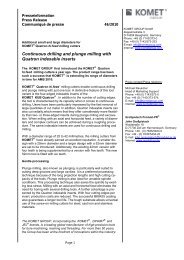
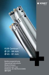
Einstellbeispiel für ����� 18,5 mm<br />
Feinverstellkopf M04 00150 Bohrstange B00 25661 � 18<br />
Erster Einstellvorgang: Verdrehwinkel der Ringe zueinander<br />
In Tabelle 1 Bearbeitungsdurchmesser (hier � 18,5 mm) festlegen. Waagrechte<br />
Hilfslinie nach rechts ziehen bis diese die Kennlinie der zu verwendenden Bohrstange<br />
kreuzt. Am Schnittpunkt eine Senkrechte bilden und den erforderlichen Verdrehwinkel<br />
(hier 126°) ablesen. Den ermittelten Wert an der Massenskala � auf die Einstellmarke<br />
� einstellen. Mit Klemmschraube � die beiden Ringe gegeneinander abklemmen.<br />
Setting example for 18.5 mm �����<br />
Micro-adjustable head M04 00150 Bohrstange B00 25661 � 18<br />
Step 1: Angle of torsion between rings<br />
Determine the machining diameter from Table 1 (in this case 18.5 mm �). Trace a<br />
vertical line to the right until this crosses the contour line for the boring bar to be used.<br />
At the intersect point, trace a horizontal line and read off the torsion angle required (in<br />
this case 126°). Set the value determined to the setting mark � on the balancing scale<br />
�. Clamp the two rings together with the clamping screw �.<br />
Exemple de réglage pour un ����� 18,5 mm<br />
Tête de finition M04 00150 Bohrstange B00 25661 � 18<br />
Première opération de réglage: angle de torsion des bagues entre elles<br />
Repérer le diamètre d'usinage dans le tableau 1 (ici � 18,5 mm). Tracer une ligne<br />
horizontale vers la droite jusqu'à ce qu'elle coupe la courbe de la barre d'alésage à<br />
utiliser. Au point d'intersection, tracer une perpendiculaire et lire l'angle de torsion<br />
nécessaire (ici 126°). Régler la valeur déterminée à l'échelle des masses � au repère<br />
de réglage �. Bloquer les deux bagues l'une par rapport à l'autre à l'aide de la vis de<br />
serrage �.<br />
Esempio per ����� 18,5 mm<br />
Testina M04 00150 Bohrstange B00 25661 � 18<br />
Primo passo: allineamento con il tagliente<br />
Definiere nella tabella 1 il diametro da barenare (p. es. � 18,5 mm) dal quale tracciare<br />
una linea orizzontale fino ad incrociare la linea stampata sul diagramma, proseguire la<br />
linea in senso verticale fino in basso e rilevare il valore (nel ns. esempio = 126°). Girare<br />
i due anelli fino a quando la lineetta � si trova in corrispondenza del valore stabilito<br />
sulla scala dell'anello � e bloccare i due anelli in questa positione tramite la vite �.<br />
�<br />
�<br />
Bitte beachten! Diagrammwerte<br />
wurden mit W30..... .32 (TOHX) ermittelt.<br />
Please note: values on diagram were<br />
calculated with W30..... .32 (TOHX).<br />
Attention: Les valeurs dans le diagramme<br />
ont été calculées avec W30..... .32 (TOHX).<br />
Attenzione! i valori del diagramma sono<br />
stati determinati con W30..... .32 (TOHX)<br />
�<br />
�<br />
�<br />
� Massenskala<br />
balancing scale<br />
Echelle des masses<br />
scala massa<br />
� Lagenskala<br />
position scale<br />
Echelles des positions<br />
scala posizione<br />
� Einstellmarke<br />
setting mark<br />
Repère de réglage<br />
lineetta di riferimento<br />
� Klemmschraube<br />
clamping screw<br />
Vis de serrage<br />
vite di fissaggio<br />
� Klemmschraube<br />
clamping screw<br />
Vis de serrage<br />
vite di fissaggio
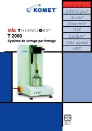
Bearbeitungsdurchmesser in mm · Machining diameter in mm · Diamètre d'usinage en mm · Diametro del foro in mm<br />
26<br />
25<br />
24<br />
23<br />
22<br />
21<br />
20<br />
19<br />
18<br />
17<br />
16<br />
15<br />
14<br />
13<br />
12<br />
11<br />
10<br />
9<br />
8<br />
Tabelle 1<br />
Table 1<br />
Tableau 1<br />
Tabella 1<br />
20° 30°<br />
Beispiel � 18,5 mm<br />
Example � 18,5 mm<br />
Exemple � 18,5 mm<br />
Esempio � 18,5 mm<br />
Bohrstange<br />
Boring Bar<br />
Barre d'alésage<br />
Bareni<br />
B0025710<br />
� 11<br />
B0025620<br />
� 10<br />
B0025700<br />
� 9<br />
B0025610<br />
� 8<br />
40° 50° 60° 70° 80° 90° 100° 110° 120°<br />
Verdrehwinkel an der Massenskala<br />
Torsion angle on the balancing scale<br />
Angle de torsion à l'échelle des masses<br />
Angolo scala massa<br />
130°<br />
140°<br />
B0025691<br />
� 24<br />
B0025681<br />
� 22<br />
B0025671<br />
� 20<br />
B0025661<br />
� 18<br />
B0025650<br />
� 16<br />
B0025640<br />
� 14<br />
B0025630<br />
� 12<br />
150°
D<br />
GB<br />
F<br />
I<br />
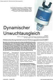
Einstellbeispiel für ����� 18,5 mm<br />
Feinverstellkopf M04 00150 Bohrstange B00 25661 � 18<br />
Zweiter Einstellvorgang: Position des <strong>Wuchtring</strong>s zur Schneide<br />
Bearbeitungsdurchmesser 18,5 mm in Tabelle 2 festlegen. Waagrechte Hilfslinie bis<br />
zur Bohrstangen-Kennlinie B0025661 ziehen. Am Schnittpunkt eine Senkrechte bilden<br />
und den Verdrehwinkel (hier 84°) ablesen. Ring auf Feinverstellkopf montieren. Den<br />
Ring gemäß dem ermittelten Verdrehwinkel positionieren. Dabei ist die Schneidkante<br />
bzw. die Werkzeugmitte mit dem entsprechenden Teilstrich von 84° in Übereinstimmung<br />
zu bringen. Mit Klemmschraube � den <strong>Wuchtring</strong> am Werkzeug klemmen. Nur bei<br />
Verwendung der Wendeschneidplatte W30 . . . . garantieren die angegebenen<br />
Einstellwerte einen optimalen Unwuchtausgleich.<br />
Setting example for 18.5 mm �����<br />
Micro-adjustable head M04 00150 Bohrstange B00 25661 � 18<br />
Step 2: Position of balancing ring in relation to the cutting edge<br />
Locate machining diameter 18.5 mm in Table 2. Trace a vertical line to rhe contour line<br />
for the boring bar B0025661. At the intersect point, trace a horizontal line and read off<br />
the torsion angle (in this case 84°). Fit the ring on the micro-adjustable head. Position<br />
the ring according to the torsion angle which has been determined. For this the cutting<br />
edge or centre of the tool should be aligned with the appropriate graduation for 84°.<br />
Using the clamping screw �, clamp the balancing ring to the tool.The setting values<br />
given will only produce optimum adjustment of any imbalance using inserts W30 . .<br />
Exemple de réglage pour un ����� 18,5 mm<br />
Tête de finition M04 00150 Bohrstange B00 25661 � 18<br />
Deuxième opération de réglage: position de la bague d'équilibrage par rapport à<br />
l'arête de coupe<br />
Repérer le diamètre d'usinage 18,5 mm dans le tableau 2. Tracer une ligne horizontale<br />
vers la courbe de la barre d'alésage B0025661. Au point d'intersection, tracer une<br />
perpendiculaire et lire l'angle de torsion (ici 84°). Monter la bague sur le tête de finition.<br />
Positionner la bague selon l'angle déterminé. Faire coïncider l'arête de coupe ou le<br />
milieu de l'outil avec la graduation de 84°. Bloquer la bague d'équilibrage sur l'outil<br />
avec la vis de serrage �. Les valeurs de réglage indiquées garantissent une<br />
compensation optimale du balourd à condition d'utiliser la plaquette amovible W30..<br />
Esempio per ����� 18,5 mm<br />
Testina M04 00150 Bohrstange B00 25661 � 18<br />
Secondo passo: allineamento con il tagliente<br />
Definire nella tabella 2 il diametro da barenare (es. 18,5 mm) e tracciare una linea<br />
orizzontale fino ad incrociare la linea del bareno B00 25661. Da questo punto<br />
proseguire in verticale verso il basso e rilevare la quota (nel ns. esempio = 84°).<br />
Montare l'anello sulla testina e orientarla in modo che il tagliente del bareno si trovi in<br />
corrispondenza di 84°. Bloccare tutto tramite la vite �.<br />
Una equilibratura ottimale si ottiene solo utilizzando inserti del tipo W30 . . . .<br />
Präzisionswerkzeuge Robert Breuning GmbH<br />
D-74351 Besigheim · Postfach 13 61 · Telefon 0 71 43 / 3 73-0 · Telefax 0 71 43 / 37 32 33 · E-mail info@komet.de<br />
399 24 241 20-5-03/01 Printed in Germany<br />
Technische Änderungen, bedingt durch Weiterentwicklung, vorbehalten. We reserve the right to make modifications.<br />
Nous nous réservons le droit de procéder aux changements techniques rendus nécessaires par l'evolution des recherches dont nos produits (et nos clients) bénéficient continuellement. Con riserva di<br />
eventuali variazioni techniche dovute ad ulteriori sviluppi.
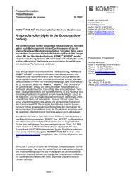
Tabelle 2<br />
Table 2<br />
Tableau 2<br />
Tabella 2<br />
Bearbeitungsdurchmesser in mm Diamètre d'usinage en mm<br />
Machining diameter in mm Diametro del foro in mm<br />
26<br />
25<br />
24<br />
23<br />
22<br />
21<br />
20<br />
19<br />
18<br />
17<br />
16<br />
15<br />
14<br />
13<br />
12<br />
11<br />
10<br />
9<br />
8<br />
Beispiel � 18,5 mm<br />
Example � 18,5 mm<br />
Exemple � 18,5 mm<br />
Esempio � 18,5 mm<br />
30°<br />
B0025671<br />
� 20<br />
B0025691<br />
� 24<br />
B0025681<br />
� 22<br />
B0025661<br />
� 18<br />
B0025630<br />
� 12<br />
Bohrstange<br />
Boring Bar<br />
Barre d'alésage<br />
Bareni<br />
B0025650<br />
� 16<br />
B0025640<br />
� 14<br />
B0025710<br />
� 11<br />
B0025620<br />
� 10<br />
B0025700<br />
� 9<br />
B0025610<br />
� 8<br />
40° 50° 60° 70° 80° 90° 100° 110°<br />
Verdrehwinkel an der Lagenskala Angle de torsion à l'échelle des positions<br />
Torsion angle on the balancing scale Angolo scala massa