ATON BARRA - Artemide
ATON BARRA - Artemide
ATON BARRA - Artemide
- TAGS
- aton
- barra
- artemide
- artemide.us

You also want an ePaper? Increase the reach of your titles
YUMPU automatically turns print PDFs into web optimized ePapers that Google loves.
Istruzioni di montaggio<br />
Instructions de montage<br />
Assembly instructions<br />
Montageanleitung<br />
Instrucciones para el montaje<br />
via Bergamo, 18<br />
Pregnana Milanese (Mi) - - Italia<br />
tel. 02.935181 - - telefax 02.93590254 02.93590496 numero verde 167.824035<br />
sito internet www.artemide.com<br />
Avvertenze:<br />
Prima di ogni operazione sull’apparecchio<br />
disinserire la tensione di<br />
rete.<br />
Attenzione:<br />
Usare esclusivamente le lampadine<br />
del tipo e potenza indicate nei<br />
dati di targa.<br />
La sicurezza elettrica dell’apparecchio<br />
è garantita con l’uso appropriato<br />
delle seguenti istruzioni. Pertanto<br />
è necessario conservarle.<br />
F<br />
<strong>ATON</strong> <strong>BARRA</strong><br />
Apparecchio in classe I - - IP 20<br />
Design: Ernesto Gismondi<br />
Avis:<br />
Note:<br />
Vorsicht:<br />
Advertencia:<br />
Déconnecter la tension deréseau Prior to any work on the fixture Von jeidem Eingriff am dem Gerät Desconectar la tensiónde red antes<br />
avant toute opération sur l’appareil. always switch off the mains. die Netzspanung unterbrechen. de cualquier operación sobre el<br />
aparato.<br />
Attention:<br />
Attention:<br />
Achtung:<br />
Atención:<br />
Employer exsclusivement les Only use bulbs of the type and wat- Ausschließlich Lampen verwenden, Utilizar exclusivamente las bombil-<br />
ampoules du type et de la puistage indicated on the rating plate. die dem auf dem auf dem Gerätelas del tipo y potencia indicados en<br />
sance indiqués sur la plaque de This equipment is guaranteed only schild angegebenen Typ und Wert la placa del aparado.<br />
l’appareil.<br />
when used as indicated in the fol- entsprechen.<br />
La seguridad del aparato está<br />
La sécurité de l’appareil n’est lowing instructions. Therefore they Die Sicherheit der Leuchte wird nur garantizada solo con el uso apro-<br />
garantie que si les instructions sui- should be kept for future reference. bei sachgerechtem Gebrauch priado de las instrucciones. Por lo<br />
vantes sont convenablement sui-<br />
gemäß folgenden Anweisungen tanto es necesario conservarlas.<br />
vies. Il est donc nécessaire de les<br />
gewährleistet. Bitte bewahren Sie<br />
conserver.<br />
diese sorgfälting auf.<br />
C<br />
A<br />
B<br />
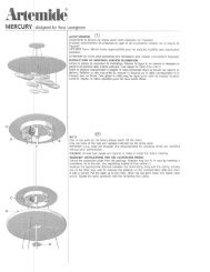
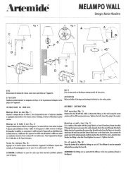
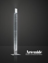
" 2 SOSPENSIONE CON ALIMENTAZIONE. Separare il fondello H dal rosone M. Fissare<br />
il fondello H al soffitto mediante le due asole poste sullo stesso. Eseguire i collegamenti elettrici<br />
all’apposito morsetto. Agganciare il cavetto di sostegno D con il fermacavo metallico O al gancio<br />
P. Allentare le due viti del fermacavo O e regolare l’altezza dell’apparecchio. Rimontare il rosone<br />
M con una leggera pressione.<br />
" 2 SOSPENSIONE (LAMPE A SUSPENSION) AVEC ALIMENTATION. Séparer la plaque<br />
de fixation H de la rosace M.FixerlaplaqueHauplafond au moyen des oeillets qui se trouvent sur<br />
elle. Effectuer les connexions électriques à la borne. Accrocher le câble de soutien D au moyen<br />
du presse- -câble métallique O au crochet P. Dévisser les deux vis du presse- -câble O et régler la<br />
hauteur de l’appareil. Remonter la rosace M avec une légère pression.<br />
" 2 SUSPENSION WITH POWER SUPPLY. Divide the bottom H from the rosette M.Tighten<br />
the bottom H against the ceiling through its two slots. Make all electrical connections of the corresponding<br />
terminal. Hook the support cable D with a metallic cable- -fastener O to the hook P. Loose<br />
the two screws of the cable- -fastener O and regulate the height of the device. Assemble the rosette<br />
M again with a slight pressure.<br />
" 2 AUFHÄNGUNG MIT STROMZUFUHR. Die Bodenscheibe H von der Deckenrosette M<br />
trennen. Die Bodenscheibe H gegen die Decke durch die zwei Löcher befestigen. Alle elektrische<br />
Anschlüsse durchführen. Das Haltekabel D mit der metallischen Kabelbefestigung O am Haken<br />
P blockieren. Die zwei Schrauben von der Kabelbefestigung O ausdrehen und die Höhe der Vorrichtung<br />
einstellen. Die Deckenrosette M mit einem leichten Druck wieder montieren.<br />
" 2 SOSPENSIONE (LAMPARA DE SUSPENSION) CON ALIMENTACION. Separar la placa<br />
de fijación H del rosetón M. Fijar la placa H al techo mediante los dos ojales que se encuentran<br />
en ella. Efectuar las conexiones eléctricas al borne. Enganchar el cable de sostén D con el prensa- -<br />
cables metálico O al gancho P. Aflojar los dos tornillos del prensa- -cables O y ajustar la altura del<br />
aparato. Volver a montar el rosetón M con una ligera presión.<br />
G<br />
" 1 SOSPENSIONE SEMPLICE. Fissare l’apposito tassello al soffitto. Agganciare<br />
il cavetto di sostegno A con il fermacavo metallico B al gancio C. Allentare le due viti del<br />
fermacavo B e regolare l’altezza dell’apparecchio. Portare fino contro il soffitto il bicchierino<br />
F ed avvitare la vite G.<br />
" 1 SUSPENSION SIMPLE. Fixer le tampon au plafond. Accrocher le câble de soutien<br />
A avec le presse- -câble métallique B au crochet C . Desserrer les deux vis du presse- -<br />
câble B et régler la hauteur de l’appareil. Placer contre le plafond le verre F et visser la vis<br />
G.<br />
" 1SIMPLEHANGING.Fasten the proper anchor on the ceiling. Hook the support<br />
cable A with the metal cable fastener B to the hook C. Unscrew the two screws of the cable<br />
fastener B and adjust the height of the device. Position the cup F against the ceiling and fastenwiththescrewG.<br />
" 1 EINFACHE AUFHÄNGUNG. Befestigen Sie den richtigen Dübel gegen die<br />
Decke. Haken Sie das Haltekabel A mit der Kabelbefestigung aus Metall B mit dem Haken<br />
C. Drehen Sie die zwei Schrauben der Kabelbefestigung B aus und stellen Sie die richtige<br />
Höhe des Geräts ein. Legen Sie das Glas F gegen die Decke und schrauben Sie Schraube<br />
G fest.<br />
" 1 SUSPENSION SENCILLA. Fijar la cuña al techo. Enganchar el cable de sostén<br />
A con el sujetacables metálico B al gancho C. Aflojar los dos tornillos del sujetacables B<br />
y ajustar la altura del aparato. Llevar contra el techo el vaso F y atornillar el tornillo G.<br />
H<br />
M<br />
D<br />
O<br />
P
L<br />
E<br />
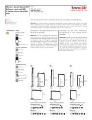
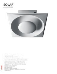
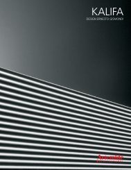
" 4 GIUNTI. Rimuovere i coperchi R facendo leva con un cacciavite nelleapposite<br />
fessure poste sui moduli <strong>ATON</strong> <strong>BARRA</strong>. Inserire il giunto S nella testata e bloccarlo con<br />
le apposite mollette Q. Eseguire il collegamento elettrico del cavo in dotazione alle morsettiere.<br />
Rimontare i coperchi R a scatto.<br />
" 4JOINTS. Oter les couvercles R en faisant pression au moyen d’un tourne- -vis,<br />
en l’introduisant dans les fentes des modules <strong>ATON</strong> <strong>BARRA</strong>.IntroduirelejointS dans<br />
la tête et le bloquer avec les pinces Q. Effectuer la connexion électrique du câble fourni<br />
avec les boîtes à bornes. Remonter les couvercles R par encliquetage.<br />
" 4JOINTS.Remove the covers R by levering with a screwdriver in the proper<br />
holes placed on the <strong>ATON</strong> <strong>BARRA</strong> modules. Insert joint S into the head and block it with<br />
the corresponding clips Q. Electrically connect the cable supplied to the terminal<br />
boards. Assemble the snap covers R again.<br />
" 4 VERBINDUNGEN. Entfernen Sie die Deckel R, indem Sie mit einem Schraubenzieher<br />
in den richtigen Löchern an den <strong>ATON</strong> <strong>BARRA</strong> Modulen aufheben. Stecken<br />
Sie die Verbindung S in den Kopf ein und blockieren Sie sie mit den entsprechenden<br />
Klammern Q. Verbinden Sie elektrisch das mitgelieferte Kabel mit den Klemmenbrettern.<br />
Bauen Sie die Abschnappdeckel R wieder an.<br />
" 4JUNTAS.Quitar las tapas R mediante un atornillador, introduciéndolo en las<br />
hendiduras que se encuentran en los módulos <strong>ATON</strong> <strong>BARRA</strong> como si fuera una<br />
palanca. Introducir la junta S en la cabeza y bloquearla con las tenacillas Q.Efectuarla<br />
conexión eléctrica del cable que se suministra con las cajas delos bornes.Volver amontar<br />
las tapas R de resorte.<br />
" 3 SOSPENSIONI. Inserire nella canalina del modulo <strong>ATON</strong> <strong>BARRA</strong> l’elemento<br />
E. Agire sulla ghiera L , avvitando o svitando per ottenere una regolazione fine dell’altezza<br />
dei moduli.<br />
" 3 SUSPENSIONS. Introduire dans le tube du module <strong>ATON</strong> <strong>BARRA</strong> l’élément<br />
E. Agir sur lavirole L, en vissantou dévissant pour obtenir un réglage soignéde lahauteur<br />
des modules.<br />
" 3HANGING.Insert the element E into the raceway of the <strong>ATON</strong> <strong>BARRA</strong> module.<br />
Screw and unscrew the ringnut L to finely adjust the height of the modules.<br />
" 3 AUFHÄNGUNGEN. Stecken Sie das Element E in die Führung des <strong>ATON</strong><br />
<strong>BARRA</strong> Moduls ein. Schrauben Sie die Nutmutter E ein und los, bis Sie die Höhe der<br />
Module fein eingestellt haben.<br />
" 3 SUSPENSIONES. Introducir en el tubillo del módulo <strong>ATON</strong> <strong>BARRA</strong> el elemento<br />
E.ActuarenlavirolaL, atornillandoo destornillandopara obtener un ajusteesmeradodelaalturadelosmódulos.<br />
" 5 GIUNTO TESTA A TESTA. Utilizzando le sospensioni regolabili i moduli devono essere<br />
uniti tra loro mediante le viti e i dadi in dotazione ad ogni modulo. Effettuato il collegamento meccanico,<br />
eseguire quello elettrico come indicato nella precedente figura.<br />
" 5 JOINT TETE A TETE . En utilisant les suspensions réglables, les modules doivent être<br />
unis l’un l’autre au moyen des vis et écrous fournis avec chaque module. Après avoir effectué la<br />
connexion mécanique, effectuer l’électrique en suivant les indications de la figure précédente.<br />
" 5 HEAD TO HEAD JOINT. Using the adjustable hanging, the modules may be joined<br />
between them with the screws and the nuts supplied with each module. After having made the<br />
mechanical connection, make the electrical one as indicated in the previous picture.<br />
" 5 KOPF GEGEN KOPF VERBINDUNGEN. Mit den einstellbaren Aufhängungen können<br />
die Modulen miteinander mit den mitgelieferten Schrauben und Muttern befestigt werden. Nachdem<br />
Sie die Teile mechanisch verbunden haben, verbinden Sie sie elektrisch, wie im vorigen Bild<br />
abgebildet.<br />
" 5 JUNTA CABEZA CON CABEZA . Utilizando las suspensiones regulables, los módulos<br />
se deben juntar entre ellos mediante los tornillos y las tuercas que se suministran con cada módulo<br />
. Después de haber efectuado la conexión mecánica, efectuar la eléctrica como indicado en la<br />
figura precedente.<br />
" 6 A seconda del tipo di sospensione adottato le estremità dei moduli vengono completate o con giunti terminali,<br />
oppure con tappi terminali da fissare a scatto sulla testata. Entrambe le soluzioni possono essere con o senza<br />
alimentazione elettrica.<br />
" 6 Les extrémités des modules peuvent être complétées ou avec des barres ou des joints terminaux, selon le<br />
type de suspension, ou avec des bouchons terminaux à fixer par encliquetage sur la tête. Toutes les deux peuvent être<br />
avec ou sans alimentation électrique.<br />
" 6. According to the kind of hanging, the ends of the module are completed with some end joints or end plugs<br />
to be snap- -fastened to the head. Both solutions may be with or without electric supply.<br />
" 6. Abhängig von der Aufhängung, werden die Enden der Modulen entweder mit Endverbidungen oder mit<br />
Endstopfen fertiggestellt, die gegen den Kopf springbefestigt werden. Beide Lösungen können mit oder ohne elektrische<br />
Speisung sein.<br />
" 6 Las extremidades de los módulos se completan o con barras o con juntas terminales, según el tipo de suspensión,<br />
o con tapones terminales a fijar de resorte en la cabeza. Ambas pueden ser con o sin alimentación eléctrica.<br />
S<br />
R<br />
L3 N L1 L2 L3<br />
N L1 L2<br />
Q
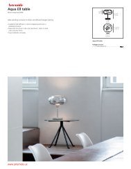
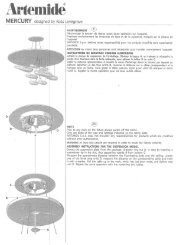
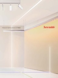
" 7 RIMOZIONE SCHERMO DIFFUSORE E PARABOL. Per le versioni con<br />
schermo parabol o diffusore far leva con la punta di un cacciavite nelle apposite fessure<br />
poste sul coperchio di chiusura R.<br />
" 7 ENLEVEMENT D’ECRAN DIFFUSEUR ET PARABOL. Pourlesversions<br />
avec écran parabol ou diffuseur, introduire la pointe d’un tourne- -vis dans les fentes<br />
du couvercle de fermeture R et faire pression.<br />
" 7 REMOVAL OF THE DIFFUSER AND PARABOL SCREEN. For the versions<br />
with the Parabol or diffuser screen, lever with the tip of a screwdriver into the<br />
corresponding holes on the closing cover R.<br />
" 7 ENTFERNUNG DES STREUENDEN ODER PARABOL SCHIRMES. Für<br />
die Versionen mit dem Parabol oder streuenden Schirm, heben Sie mit einem<br />
Schraubenzieher in den entsprechenden Löcher am Deckel R auf.<br />
" 7 REMOCION DE PANTALLA DIFUSOR Y PARABOL.Enlasversionescon<br />
pantalla parabol o difusor, introducir la punta de un atornillador en las hendiduras<br />
que se encuentran en la tapa de cierre R y utilizarlo como si fuera un palanca.<br />
" 8 RIMOZIONE DIFFUSORE LAMELLARE E ALH. Indossare i guanti in dotazione. Afferrare le due lamelle di estremità e tirare con moderazione verso il<br />
basso.<br />
" 8 ENLEVEMENT DE DIFFUSEUR LAMELLAIRE ET ALH. Mettre les gants fournis. Prendre les deux lamelles d’extrémité et tirer avec modération vers le bas.<br />
" 8 REMOVAL OF THE LAMINAR AND ALH DIFFUSER. Wear the gloves supplied. Seize the two end reeds and moderately pull downwards.<br />
" 8 ENTFERNUNG DES LAMELLEN- - UND ALHSCHIRMES. Ziehen Sie die mitgelieferten Handschuhe an. Greifen Sie die zwei Endlamellen und ziehen Sie<br />
nach unten.<br />
" 8 REMOCION DE DIFUSOR LAMINAR Y ALH. Ponerse los guantes que se suministran . Tomar las dos laminas de extremidad y tirar con moderación hacia<br />
lo bajo.<br />
" 9 Per rimontare gli schermi diffusore e lamellare operare come indicato in figura 9a ; Per rimontare i diffusori ALH e PARABOL mantenere il diffusore parallelo<br />
al modulo e spingere delicatamente fino allo scatto delle molle. ( 9b).<br />
" 9 Pour remonter les écrans diffuseur et lamellaire suivre les indications de la figure 9a; pour remonter les diffuseurs ALH et PARABOL maintenir le diffuseur<br />
parallèle au module et pousser doucement jusqu’au décliquetage des ressorts<br />
(9b ).<br />
" 9 To assemble the diffuser and laminar screens proceed as indicated in picture 9a. To assemble the ALH and PARABOL diffusers again, keep the diffuser<br />
parallel to the module and delicately push till the two springs click (9b)<br />
" 9. Um die Streuend- - und Lamellenschirm wieder anzubauen, verfahren Sie wie im Bild 9a abgebildet. Um die streuenden Körper ALH und PARABOL wieder<br />
anzubauen, halten Sie den streuenden Körper parallel mit dem Modul und schieben Sie zärtlich, bis die Feder springen (9b).<br />
" 9 Para volver a montar las pantallas difusor y laminar obrar como indicado en la figura 9a; para volver a montar los difusores ALH y PARABOL mantener el<br />
difusor paralelo al módulo y apretar suavemente hasta hacer disparar los muelles (9 b).<br />
9a<br />
R<br />
9b
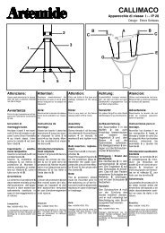
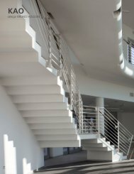
Linea di alimentazione lampada con interruzione<br />
Ligne d’alimentation de la lampe avec interruption.<br />
Line for lamp feeding with interruption.<br />
Linie der Lampspeisung mit Unterbrechung.<br />
Línea de alimentación lámpara con interrupción<br />
Ne<br />
N<br />
L<br />
Le<br />
L3<br />
N<br />
L1<br />
L2<br />
Linea non interrotta per alimentazione di emergenza.<br />
Ligne ininterrompue pour alimentation d’urgence.<br />
Non- -stop line for emergency feeding.<br />
Ununterbrochen Linie für Notspeisung.<br />
Líneanointerrumpidaparaalimentaciónde<br />
emergencia<br />
10 ... Allacciamento elettrico modulo per lampade di emergenza a luce permanente.<br />
ATTENZIONE: in presenza di questo modulo non deve essere eseguito il collegamento descritto nella figura 4.<br />
Effettuare il collegamento elettrico come indicato nello schema elettrico solo per i moduli emergenza.Caratteristiche:<br />
Lampada fluorescente 26 (G13). Incorpora un dispositivo che controlla e verifica:<br />
" La presenza della rete di alimentazione (spia rossa accesa).<br />
" La batteria in carica (spia rossa accesa).<br />
Batteria al nikel cadmio. Tipo ermetico, esente da manutenzione. Tempo di ricarica della batteria: 18 ore. Autonomia<br />
del complesso in funzionamento di emergenza: 1 ora.<br />
10 ... Connection électrique du module pour lampes d’urgence à lumière permanente. ATTENTION: la connection décriteenfigure4nedoitpasêtreeffectuéeenprésencedecemodule.<br />
Effectuer le branchement électrique comme indiqué dans le schéma électrique, seulement pour les modules d’urgence.<br />
Caractéristiques:<br />
Lampe fluorescente ø26 (G13). Elle a un dispositif pour contrôler:<br />
" la présence du réseau d’alimentation (témoin rouge allumé).<br />
" la batterie en charge (témoin rouge allumé).Batterie au nickel cadmio. Type hermétique, sans entretien. Temps de<br />
recharge de la batterie: 18 heures. Autonomie de l’appareil pendant le fonctionnement d’urgence: 1 heure.<br />
10 ... Electric connection of the module for permanent light emergency lamp. WARNING: the connection described<br />
in figure 4 must not be carried out when this module is present.<br />
Carry out the electric connection as shown in the electric diagram for emergency modules only. Characteristics:<br />
Fluorescent lamp ø26 (G13). It is equipped with a device to check:<br />
" feeding network presence (red light on)<br />
" battery in charge (red light on).Cadmium nickel battery. Hermetic kind,without maintenance.Battery recharge time:<br />
18 hours. Autonomy during emergency: 1 hour.<br />
10 ... Elektrischer Anschluß des Moduls für die Dauerndslichtnotlampe.VORSICHT: man muß nicht den Anschluß, der<br />
im Bild 4 geschrieben ist, durchführen, wenn gibt es dieser Modul.<br />
Den elektrischen Anschluß durchführen, wie es im Schaltplan nur für die Notmoduln beschrieben ist. Kennzeichen:<br />
Fluoreszenzlampe ø26 (G13). Sie hat eins Kontrollegerät für:<br />
" Die Anwesenheit des Versorgungsnetzs (Rotleuchte einschaltet).<br />
" Die Batterie in Ladung (Rotleuchte einschaltet).Nickelkadmiumbatterie. Hermetischer Typ ohne Unterhaltung. Aufladungszeit<br />
der Batterie: 18 Stunden. Selbständigkeit des Geräts während des Notbetriebs: 1 Stunde.<br />
10 ... Conexión eléctrica módulo para lámparas de emergencia a luz permanente ATENCION : en presencia de este módulo no se debe efectuar la conexión descrita en la<br />
figura 4.<br />
Efectuar la conexión eléctrica como indicado en el esquema eléctrico sólo para módulos de emergencia. Características:<br />
Lámpara fluorescente ø26 (G13). Incluye un dispositivo que controla y verifica :<br />
" La presencia de la red de alimentación (luz roja encendida).<br />
" La batería bajo carga (luz roja encendida).Batería niquél cadmio.Tipo hermético,no necesita mantenimientos. Tiempo para recargar la batería: 18 horas.Autonomía del grupo<br />
en funcionamiento de emergencia : 1 hora.<br />
Lampadine:<br />
18 - - 36 - - 58W FD ; Moduli alogeni: 300W HD. Solo per moduli alogeni : nei moduli alogeni è necessario sostituire il vetro di protezione quando questo è fessurato o danneggiato, prima<br />
di utilizzare l’apparecchio.<br />
Sostituire al più presto le lampadine esaurite. In corrispondenza della sostituzione delle lampadine è opportuna anche la sostituzione dello starter corrispondente (dove applicabile). L’uso<br />
prolungato di lampadine o starter esauriti può danneggiare l’apparecchio.<br />
Ampoules: 18--36--58WFD;Modules halogènes: 300W HD ; Seulement pour modules halogènes : dans les modules halogènes il est nécessaire remplacer le verre de protection<br />
en cas de fissure ou dommage, avant d’utiliser l’appareil.<br />
Remplacer les ampoules déchargées le plus tôt possible. Pendant le remplacement des ampoules, il est nécessaire aussi effectuer le remplacement du relais correspondant pour l’allumage<br />
(où l’on peut l’appliquer). L’usage prolongé des ampoules ou des relais déchargés peut endommager l’appareil.<br />
Bulbs: 18 - - 36 - - 58W FD ; Halogen modules: 300W HD ; For halogen modules only: It is necessary to replace the protection glass in the halogen modules in case it is fissured or damaged,<br />
before using the fixture.<br />
Replace, as soon as possible, the discharged bulbs. At the same time of the bulbs replacement, it is also necessary the replacement of the corresponding starter (where possible). The prolonged<br />
use of the discharged bulbs or starters can damage the fixture.<br />
Glühlampen: 18 - - 36 - - 58W FD ; Halogenmoduln: 300W HD ; Nur für Halogenmoduln Moduln: Man muß das Schutzglas in den Halogenmoduln Moduln ersetzen, wenn es gespaltet<br />
oder beschädigt ist, vor dem Gerät zu benutzen. Die entladenen Glühlampen, so bald wie möglich auswechseln. Gleichzeitig die Ersetzung der Glühlampen, man muß auch die Ersetzung<br />
des entsprechenden Starters ausführen (wo möglich). Den anhaltenden Gebrauch von entladenen Glühlampen oder Starter kann das Gerät beschädigen.<br />
Bombillas:18--36--58WFD;Módulos halógenos : 300W HD ; Sólo para módulos halógenos : en los módulos halógenos hay que sustituir el vidrio de proteccióncuando este muestra<br />
hendiduras o daños, antes de utilizar el aparato.<br />
Sustituir pronto las bombillas descargadas. Cuando se sustiuyen las bombillas efectuar también la sustitución del starter correspondiente (donde se puede aplicar). El uso prolongado de<br />
bombillas o starter descargados puede dañar el aparato.<br />
...<br />
Il numero racchiuso nel simbolo indica la distanza<br />
minima in metri alla quale vanno posti gli oggetti<br />
da illuminare. La distanza viene misurata sull’asse<br />
ottico dell’apparecchio dalla parte dell’apparecchio<br />
o della lampada piú vicina all’oggetto illuminato.<br />
Le numéro renfermé dans le symbole indique la<br />
distance minimale en mètres à respecter pour la<br />
mise en place des objets à illuminer. La distance<br />
est mesurée sur l’axe optique de l’appareil de la<br />
part de l’appareil ou de la lampe plus près de l’objet<br />
illuminé.<br />
The number enclosed within the symbol indicates<br />
the minimum distance in metres to which the<br />
objects to be illuminated should be placed. The<br />
distance is measured on the axis of vision of the fixture<br />
from the fixture side or from the lamp nearer<br />
to the illuminated object.<br />
Die im Symbol enthaltene Nummer bezeichnet die<br />
mindeste Entfernung auf Meter, zu der die<br />
beleuchtenden Gegenstände gesetzt werden sollten.<br />
Die Entfernung wird auf der Zielachse des<br />
Geräts aus der Seite des Geräts oder aus der<br />
Leuchte, die näher zum beleuchteten Gegestand<br />
steht, ausgemessen.<br />
El número encerrado en el símbolo indica la distancia<br />
mínima en metros para colocar los objetos<br />
que se deben iluminar. La distancia se mide sobre<br />
el eje óptico del aparato desde la parte del aparato<br />
o de la lámpara más cercana al objeto iluminado.<br />
F<br />
Il simbolo indica l’idoneitá degli apparecchi al montaggio<br />
diretto su superfici normalmente infiammabili.<br />
Gli apparecchi privi del suddetto simbolo sono<br />
idonei ad essere installati esclusivamente su<br />
superfici non combustibili.<br />
Le symbole indique que les appareils sont indiqués<br />
pour être montésdirectement sur des surfacesnormalement<br />
inflammables. Les appareils ne portant<br />
pas ce symbole peuvent être montés exsclusivement<br />
sur des surfaces non combustibles.<br />
The symbol indicates the suitabily of fixtures to be<br />
mounted directly on normaly inflammable surfaces.<br />
Fixtures without the above symbol are only<br />
suitable for installation on non- -inflammable surfaces.<br />
Das Symbol zeigt an, ob die Geräte dazu geeignet<br />
sind, auf normal entflammbaren Oberflächen<br />
angebracht zu werden. Geräte ohne dieses Symbol<br />
sind ausschließlich dazu geeignet, auf nicht<br />
entflammbaren Oberflächen angebracht zu werden.<br />
El símbolo indica que los aparatos son aptos para<br />
ser montadosdirectamente sobre superficies normalmente<br />
inflamables. Los aparatos desprovistos<br />
de dicho símbolo pueden ser instalados exsclusivamente<br />
sobre superficies no combustibles.<br />
Tutti i prodotti ARTEMIDE che rientrano nell’ambito di applicazione della direttiva<br />
europea compatibilitá elettromagnetica E.M.C. 89/336 e successive modifiche<br />
92/31 e 93/68, e/o della direttiva europea bassa tensione B.T. 73/23 e successiva<br />
modifica 93/68, soddisfano ai requisiti richiesti e recano la marcatura ” ”.<br />
Tous les produits ARTEMIDE appartenants au champ d’application de la directive<br />
européenne compatibilité électromagnétique E.M.C. 89/336 et modifications<br />
successives 92/31 et 93/68, et/ou de la directive européenne basse tension B.T.<br />
73/23 et modification sucessive 93/68, remplissent les conditions prévues et portent<br />
le marquage ” ”.<br />
All ARTEMIDE products falling within the range of application of the European<br />
electromagnetic compatibility E.M.C. directive 89/336 and subsequent amendment<br />
92/31 and 93/68, and/or the European low voltage directive B.T. 73/23 and<br />
subsequent amendment 93/68, meet the required specifications and bear<br />
” ” labelling.<br />
Alle Produkte von ARTEMIDE, die unter das Anwendungsgebiet der europäischen<br />
Richtlinien der elektromagnetischen Kompatibilität E.M.C. 89/336 und<br />
nachfolgende Änderungen 92/31 und 93/68 und/oder der europäischen Richtlinie<br />
der Niederspannung B.T. 73/23 und nachfolgende Änderung 93/68 fallen,<br />
entsprechen den erforderlichen Eigenschaften und tragen das” ”- -Kennzeichen.<br />
Todos los productos ARTEMIDE que pertenencen al ámbito de aplicación de la<br />
directiva europea sobre compatibilidad electromagnética E.M.C. 89/336 y modificaciones<br />
sucesivas 92/31 y 93/68, y/o de la directiva europea baja tensión B.T.<br />
73/23 i modificación 93/68, cumplen los requisitos correspondientes y llevan el<br />
marcado ” ”.