PL7 INTERBUS Modicon Premium.pdf - Avenir Formation
PL7 INTERBUS Modicon Premium.pdf - Avenir Formation PL7 INTERBUS Modicon Premium.pdf - Avenir Formation
Module TSX IBX 100 Plage d’adresse La position du micro-interrupteur définit l’adresse de base suivante : Position IRQ Remarque 0 INT 10 Non standard 1 INT 11 Non standard 2 INT 2/9 Non standard 3 INT 3 Standard : correspond aux ports COM 2 et COM 4 4 INT 4 Standard : correspond aux ports COM 1 et COM 3 5 INT 5 Non standard 6 INT 12 Non standard 7 INT 15 Non standard 8 Aucun Non utilisé 9 Aucun Non utilisé 56 35011066.03 07/2008
Comment monter le module dans un PC Module TSX IBX 100 Prérequis Avant l'installation de cartes dans un PC, il est nécessaire de mettre le PC hôte hors tension et d’ouvrir le capot du PC. La mise en oeuvre d'une carte TSX IBX 100 nécessite au préalable l'installation d'un processeur de type PCX 57 dans le PC hôte. Voir Compatibilités matérielles. Il est conseillé de se reporter à l'instruction de service du processeur PCX 57 s’il n’est pas présent dans le PC hôte. Marche à suivre La procédure suivante indique comment monter un module TSX IBX 100 dans un PC et son raccordement avec le processeur PCX 57. Etape Action Illustration 1 Enlevez de son emplacement la terminaison de ligne A/ située sur le processeur PCX 57. 2 Mettez en lieu et place la carte fille fournie avec la carte TSX IBX 100. 35011066.03 07/2008 57 1 2
- Page 6 and 7: Chapitre 4 Présentation du module
- Page 8 and 9: 8 35011066.03 07/2008
- Page 10 and 11: A propos de ce manuel 10 35011066.0
- Page 12 and 13: Généralités Présentation Introd
- Page 14 and 15: Généralités Bus interstation Pr
- Page 16 and 17: Généralités Bus local Présentat
- Page 18 and 19: Caractéristiques 2.1 Performances
- Page 20 and 21: Caractéristiques Temps de transmis
- Page 22 and 23: Caractéristiques Temps de réponse
- Page 24 and 25: Caractéristiques Taux de transmiss
- Page 26 and 27: Caractéristiques 26 35011066.03 07
- Page 28 and 29: Coupleur TSX IBY 100 3.1 Descriptio
- Page 30 and 31: Coupleur TSX IBY 100 Eléments Le t
- Page 32 and 33: Coupleur TSX IBY 100 Connectique Co
- Page 34 and 35: Coupleur TSX IBY 100 3.2 Installati
- Page 36 and 37: Coupleur TSX IBY 100 3.3 Spécifica
- Page 38 and 39: Coupleur TSX IBY 100 Logicielles Le
- Page 40 and 41: Coupleur TSX IBY 100 Conditions de
- Page 42 and 43: Coupleur TSX IBY 100 42 35011066.03
- Page 44 and 45: Module TSX IBX 100 4.1 Description
- Page 46 and 47: Module TSX IBX 100 Description phys
- Page 48 and 49: Module TSX IBX 100 Implantation log
- Page 50 and 51: Module TSX IBX 100 4.2 Installation
- Page 52 and 53: Module TSX IBX 100 Comment configur
- Page 54 and 55: Module TSX IBX 100 Plage d’adress
- Page 58 and 59: Module TSX IBX 100 Etape Action Ill
- Page 60 and 61: Module TSX IBX 100 Comment configur
- Page 62 and 63: Module TSX IBX 100 Compatibilités
- Page 64 and 65: Module TSX IBX 100 Caractéristique
- Page 66 and 67: Mise en oeuvre logicielle 5.1 Gén
- Page 68 and 69: Mise en oeuvre logicielle Principe
- Page 70 and 71: Mise en oeuvre logicielle 1 Program
- Page 72 and 73: Mise en oeuvre logicielle Adressage
- Page 74 and 75: Mise en oeuvre logicielle Exemple L
- Page 76 and 77: Mise en oeuvre logicielle 5.2 Confi
- Page 78 and 79: Mise en oeuvre logicielle Ecran de
- Page 80 and 81: Mise en oeuvre logicielle Données
- Page 82 and 83: Mise en oeuvre logicielle La case C
- Page 84 and 85: Mise en oeuvre logicielle Données
- Page 86 and 87: Mise en oeuvre logicielle Comment c
- Page 88 and 89: Mise en oeuvre logicielle Comment c
- Page 90 and 91: Mise en oeuvre logicielle 5.3 Progr
- Page 92 and 93: Mise en oeuvre logicielle Mise en o
- Page 94 and 95: Mise en oeuvre logicielle Exemple d
- Page 96 and 97: Mise en oeuvre logicielle Représen
- Page 98 and 99: Mise en oeuvre logicielle Requête
- Page 100 and 101: Mise en oeuvre logicielle Requête
- Page 102 and 103: Mise en oeuvre logicielle Requête
- Page 104 and 105: Mise en oeuvre logicielle Requête
Module TSX IBX 100<br />
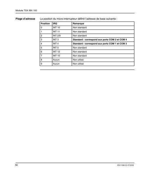
Plage d’adresse La position du micro-interrupteur définit l’adresse de base suivante :<br />
Position IRQ Remarque<br />
0 INT 10 Non standard<br />
1 INT 11 Non standard<br />
2 INT 2/9 Non standard<br />
3 INT 3 Standard : correspond aux ports COM 2 et COM 4<br />
4 INT 4 Standard : correspond aux ports COM 1 et COM 3<br />
5 INT 5 Non standard<br />
6 INT 12 Non standard<br />
7 INT 15 Non standard<br />
8 Aucun Non utilisé<br />
9 Aucun Non utilisé<br />
56 35011066.03 07/2008


