FITSTAR - Gegenschwimmanlage Double-Jet für Fliesen- und ...
FITSTAR - Gegenschwimmanlage Double-Jet für Fliesen- und ...
FITSTAR - Gegenschwimmanlage Double-Jet für Fliesen- und ...

Create successful ePaper yourself
Turn your PDF publications into a flip-book with our unique Google optimized e-Paper software.
Stand 11/2008<br />
Eine Marke der<br />
Hugo Lahme GmbH<br />
brands of Hugo Lahme GmbH<br />
<strong>FITSTAR</strong> - <strong>Gegenschwimmanlage</strong> <strong>Double</strong>-<strong>Jet</strong><br />
<strong>für</strong> <strong>Fliesen</strong>- <strong>und</strong> Folienbecken<br />
<strong>FITSTAR</strong> - counter-current-system <strong>Double</strong>-<strong>Jet</strong><br />
for tile and liner pools<br />
<strong>FITSTAR</strong> - nage à contre-courant <strong>Double</strong>-<strong>Jet</strong><br />
pour bassin carrelé et liner<br />
1<br />
Art. Nr.: 577399
Eine Marke der<br />
Hugo Lahme GmbH<br />
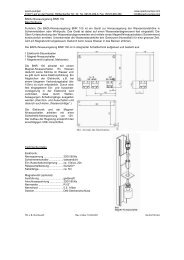
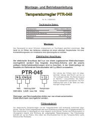
Anschlussssatz <strong>Double</strong> - <strong>Jet</strong><br />
Fittings <strong>Double</strong> - <strong>Jet</strong><br />
Ensemble de raccordement <strong>Double</strong> - <strong>Jet</strong><br />
ACHTUNG:<br />
Bei Wasserattraktionen kann während längerer Stillstandzeiten das stagnierende Wasser im Rohrsystem verkeimen <strong>und</strong><br />
dadurch das Beckenwasser hygienisch belasten. Um dieser Verkeimungsgefahr entgegenzuwirken <strong>und</strong> die hygienische<br />
Anforderung der DIN zu erfüllen, wird empfohlen, einen Teilstrom des Reinwassers über einen geregelten Bypass zur<br />
Zwangsdurchströmung in das Rohrsystem der Wasserattraktionen zu führen. Eine weitere Möglichkeit zur Erhaltung der<br />
erforderlichen Grenzwerte ist ebenfalls über eine Zwangslaufschaltung gegeben.<br />
ATTENTION:<br />
Regarding water attractions the stagnation water in the tubing system may germinate and load the basin water in an<br />
insanitary way during longer downtimes. For avoiding any germination risc and for fulfilling the sanitary demand of<br />
the DIN standard, it is recommended to lead a part of the pure water flow through a regulated bypass. The purpose of<br />
this measure consists of creating a forced current into the tubing system of the water attraction. Another possibility for<br />
maintaining the necessary limit values is a controlled movement circuit.<br />
ATTENTION:<br />
Les attractions aquatiques peuvent, lors d`un arrêt prolongé, avoir une contamination d`eau stagnante dans les<br />
tuyauteries. Cette possibilité peut provoquer une contamination bactérielle résiduelle dans le volume du bassinlors de la<br />
remise en service. Afin de remédier à cet effet et de respecter les normes d`hygiène, nous recommandons d'installer sur<br />
le circuit primaire une vanne de dérivation bi-directionnelle de purge vers circuit eau usée et arrivée d´eau propre afin<br />
de faire un rinçage de l´installation de près mise en service. Une autre possibilité consiste à installer une commande<br />
périodique de mise en marche.<br />
Anschlusssatz <strong>für</strong> Folien- <strong>und</strong> <strong>Fliesen</strong>becken aus Rotguss Art. Nr.: 8260020, aus Bronze Art. Nr.: 8260021.<br />
Fittings for liner and tile pools made of gun-metal code 8260020, made of bronze code 8260021.<br />
Ensemble de raccordement pour bassin beton carrelé et liner en laiton rouge réf. 8260020,<br />
ou en bronze réf. 8260021.<br />
Stand 11/2008 Art. Nr.: 577399<br />
2<br />
�<br />
�<br />
�<br />
�<br />
�<br />
�<br />
�<br />
�<br />
�<br />
�<br />
�<br />
��<br />
��<br />
��
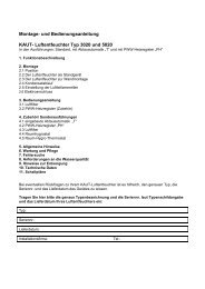
Art. Nr.: / code / réf. 8260020<br />
Restliche Positionen siehe vorstehende Tabelle!<br />
The other positions are in the preceeding table!<br />
Les autres positions se trouvent au tableau précédent.<br />
Zusatzteile gehören nicht zum Lieferumfang <strong>und</strong> sind gesondert anzufordern!<br />
Flanschsatz mit Dichtungen <strong>und</strong> Schrauben Art. Nr.: 8270050 <strong>und</strong> 8270051 (Bronze).<br />
Accessories are not part of the standard unit and have to be ordered seperately!<br />
Flange kit with seals and screws code 827005 and 8270051 (bronze).<br />
Les accessoires ne faisant par partie du kit ceux-ci sont à commander séparément!<br />
Flasque avec joint et vis de fixation réf. 8270050 laiton 8270051 bronze.<br />
Stand 11/2008<br />
Eine Marke der<br />
Hugo Lahme GmbH<br />
Pos. / item Stk. / quan. Art. Nr.: / code / réf. Artikelbezeichnung / product type / type de produit<br />
Armaturensatz / Art. Nr.: / code / réf. 8261020<br />
1. 2 7690020 Einstrahldüse / injection nozzle / buse d'injection<br />
2. 1 8715220 Sensorschaltereinsatz / sensor switch / interrupteur optique<br />
3. 2 8671520 Ansaugsieb / suction sieve / crépine Ø200<br />
4. 2 501510 Schlauchtülle / hose nozzle / embout de tuyau<br />
5. 4 500508 Schlauchschelle / hose clip / collier<br />
6. 2 510580 Schlauch NW 19 / hose Ø19 / tuyau Ø19<br />
7. 2 7309150 Rückschlagventil / return valve / clapet anti-retour<br />
Anschlusselement / Art. Nr.: / code / réf. 8261050<br />
8. 1 7691150101 Druckverteiler / pressure distributor / distributeur de pression<br />
9. 2 7184050 Schieber / valve / vanne papillon G2½<br />
10. 1 7158550 Pumpendruckstutzen / pump pressure socket / embout de sortie de<br />
pompe G2½, 90°<br />
11. 1 7754050 Pumpe, DS / pump, 3 phase / pompe, Trie 2,6 kW<br />
12. 1 7336550 Schaltung / control / boîtier de commande<br />
Art. Nr.: / code / réf. 8260021<br />
Pos. / item Stk. / quan. Art. Nr.: / code / réf. Artikelbezeichnung / product type / type de produit<br />
Armaturensatz / Art. Nr.: / code / réf. 8261021<br />
2. 1 8715221 Sensorschaltereinsatz / sensor switch / interrupteur optique<br />
4. 2 4252051131 Schlauchtülle / hose nozzle / embout de tuyau<br />
Anschlusselement / Art. Nr.: / code / réf. 8261051<br />
8. 1 7691151121 Druckverteiler / pressure distributor / distributeur de pression<br />
9. 2 7184051 Schieber / valve / vanne papillon G2½<br />
10. 1 7158551 Pumpendruckstutzen / pump pressure socket / embout de sortie de<br />
pompe G2½, 90°<br />
11. 1 7754051 Pumpe, DS / pump, 3 phase / pompe, Trie 2,6 kW<br />
Art. Nr.: 577399<br />
3
Eine Marke der<br />
Hugo Lahme GmbH<br />
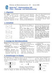
Einbauhinweise<br />
Installation Instructions<br />
Mise en place de la pièce à sceller<br />
Stand 11/2008 Art. Nr.: 577399<br />
4<br />
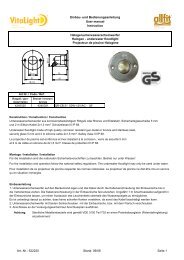
ACHTUNG: Sämtliche Metalleinbauteile sind gemäß VDE 0100 Teil 702 an einen Potentialausgleich<br />
(Potentialringleitung) anzuklemmen.<br />
ATTENTION: All metal mounting parts have to be crossbonded and earthed (closed potential circuit) in an<br />
approved manner!<br />
ATTENTION: Toutes les piéces à insérer en métal sont à relier au circuit équipotentiel.<br />
(Circuit équipotentiel en boucle)<br />
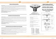
Einbaubeispiel / Installation example / Exemple de montage<br />
��������<br />
�������������������������������������������<br />
���<br />
���������<br />
����<br />
Schaltung<br />
Wiring<br />
Commande electro<br />
���<br />
���������������������������������������������<br />
�����������������������������������<br />
������������������������������������������������������������<br />
���������������������������������������������������<br />
������������������������������������������������������������������������������<br />
��������������������������������������������������������������������<br />
Elektrischer Anschluss (bauseits zu erstellen)<br />
Für den Schaltkasten wird ein Zuleitungskabel von 5 x 2,5 mm² benötigt. Absicherung 16 Ampere träge.<br />
Fehlerstromschutzschalter (FI-Schalter / Nennfehlerstrom 30 mA), der <strong>für</strong> die <strong>Gegenschwimmanlage</strong> bestimmt ist muss in jedem Fall<br />
installiert werden. Das Zuleitungskabel von der Schaltung zur Drehstrom-Pumpe ist 4 x 2,5 mm².<br />
Einbau der Schaltung<br />
Die maximale Entfernung der Schaltung vom Sensortaster beträgt 25 m.<br />
Die Schaltung ist in einem trockenen Raum zu installieren.<br />
Zur Sicherung der Pumpe ist ein Motorschutzrelais in die Schaltung eingebaut. Dieses Motorschutzrelais muss bauseitig eingestellt<br />
werden. Die Stromaufnahme der einzelnen Phasen ist im Betriebszustand zu messen.<br />
Das Motorschutzrelais ist auf den Nennstrom des Motors einzustellen. Eine Funktionsprüfung ist unbedingt erforderlich.<br />
ACHTUNG: Die Vorschriften des VDE <strong>und</strong> des örtlichen EVU (Elektrizitäts-Versorgungs-Unternehmen) sind bei<br />
der Installation der Anlage unbedingt zu beachten. Installation nur durch einen beim örtlichen EVU<br />
zugelassenen Elektro-Installateur, nach VDE 0100 Teil 702 <strong>und</strong> 430 ausführen lassen.
Stand 11/2008<br />
Eine Marke der<br />
Hugo Lahme GmbH<br />
Electrical connection (to be made on site)<br />
You need a power supply cable. 5 x 2.5 mm² for the control box. Delay fuse 16 ampere.<br />
The Residual Current Device (RCD FI-stream protection 30mA) which is designated for the counter-current has to be installed always.<br />
The power supply cable of the control to the three-phase current pump is 4 x 2.5 mm².<br />
Installation of the control<br />
The maximum distance from the control to the sensor switch is 25 m.<br />
The control has to be installed in a dry place.<br />
A relay for motor protection is built in the control for the protection of the pump. This relay for motor protection has to be adjusted<br />
on site. The power input of the seperate phases has to be measured during the operation process. The relay for motor protection has<br />
to be adjusted to the measured rated current of the motor. A control of this function is absolutly necessary.<br />
ATTENTION: During the installation you have to follow the installation regulations and regulations of the responsible<br />
Energy Supply Company. The installation work has to be conducted only by a certified electrician<br />
according to German standard VDE 0100 part 702 and 430.<br />
Raccordement électrique (hors construction)<br />
Le raccordement de la pompe doit être effectué à l´aide d´un câble 5x 2,5 mm² d´une protection primaire avec un fusible de 16 A/T<br />
et d´un disjoncteur différentiel de perte 0,30 mA est nécessaire pour la station de nage à contre courant, cette protection<br />
supplémentaire suivant la norme C 1500 /VDE 010013 N. doit être installée.<br />
Le câble d´alimentation de la commande à la pompe est 4 x2,5 mm².<br />
Mise en Place d´un interrupteur optique:<br />
La distance maximum de la commande au boîtier de commande est de 25 m .<br />
La commande est à installer dans un local sec.<br />
Le relais thermique pour la protection de pompe se trouve dans la commande.<br />
L´installateur électricien doit calibrer le relais thermique en fonction d´une mesure de courant nominal (pince ampèrmetrique)<br />
nécessaire sur les phases. Un contrôle de fonction est absolumment necessaire.<br />
ATTENTION: Les réglementations VDE et des distributeurs d´énergie régionaux, sont obligatoirement à respecter.<br />
L´installation ne doit être réalisée que par un électricien agrée par ces organismes, et avoir les connaissances des<br />
différentes normes VDE 0100 § 702 et 430 et de la C 1500 -702.<br />
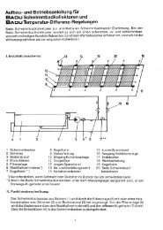
Schaltbild Schaltung<br />
Art. Nr.: 7336550<br />
Circuit diagram<br />
code 7336550<br />
Schéma de raccordement<br />
réf. 7336550<br />
ACHTUNG:<br />
Die Schaltleistung der Steuerplatine<br />
vom Sensorschalter beträgt max. 1 Ampere!<br />
Motorschutzrelais einstellen!<br />
ATTENTION:<br />
The power of the control panel<br />
of the sensor switch is 1 ampere max.!<br />
Adjust the relay for motor protection!<br />
ATTENTION:<br />
La puissance maximum d'interruption du<br />
relais interne de la platine est 1 ampère!<br />
Calibrer le relais thermique!<br />
Art. Nr.: 577399<br />
5
Eine Marke der<br />
Hugo Lahme GmbH<br />
Einbau- <strong>und</strong> Bedienungsanleitung<br />
1. Standort<br />
Es wird empfohlen, das Pumpenaggregat der <strong>Gegenschwimmanlage</strong> so anzuordnen, dass die Verbindung zwischen Pumpe <strong>und</strong><br />
Armaturenteilen so kurz wie möglich gehalten wird. Es ist auf jeden Fall darauf zu achten, dass der Einbau des Pumpenaggregates so<br />
vorgenommen wird, dass die Achse waagerecht verläuft. Es ist möglich, dass der Standort der Pumpen aus baulichen Gründen verlegt<br />
wird. Damit nicht zu grosse Strömungsverluste in der Saugleitung auftreten, empfehlen wir eine Entfernung von max. 5 m nicht zu<br />
überschreiten, wobei darauf zu achten ist, dass bei diesem Maximalbereich die Rohre knickfrei <strong>und</strong> waagerecht verlegt werden.<br />
Bei grösseren Entfernungen muss der Querschnitt der Rohrleitung entsprechend vergrössert werden. Der Standort der Pumpe ist so<br />
zu wählen, dass eine Umgebungstemperatur von 40° Celcius nicht überschritten wird. Da das Pumpenaggregat serienmässig<br />
nicht selbstansaugend ist, ist es unterhalb des Wasserspiegels zu legen. Die Pumpe <strong>und</strong> Absperrelemente müssen jederzeit leicht<br />
zugänglich sein. Eine Be- <strong>und</strong> Entlüftung sowie Bodenablauf sind unbedingt im Pumpenschacht vorzusehen.<br />
2. INSTALLATION<br />
Die Anlage wird serienmäßig mit allen erforderlichen Wandeinbauteilen <strong>und</strong> Anschlusselementen geliefert. Die Einbaugehäuse<br />
Druckseite müssen so eingebaut werden, daß die Mitte der Strahldüsen ca. 200 - 250 mm unter dem Wasserspiegel liegen <strong>und</strong> einen<br />
Mindestabstand zur seitlichen Wand von 1,5 m haben. Der Abstand der Strahldüsen zueinander beträgt 150 mm. Mit der mitgelieferten<br />
Bohrschablone lassen sich problemlos die Bohrungen <strong>für</strong> die Einbaugehäuse in die Beckenwand bringen. Hinweise auf der<br />
Bohrschablone beachten.<br />
Die Einbaugehäuse Saugseite sollten so eingebaut werden, daß die Mitte der Gehäuse 800 mm unter dem Wasserspiegel liegt.<br />
Der Abstand der Ansauggehäuse zueinander sollte 2 m betragen. Mit der mitgelieferten Bohrschablone lassen sich problemslos<br />
die Bohrungen <strong>für</strong> das Einbaugehäuse in die Beckenwand bringen. Nach Fertigstellung der Bauarbeiten <strong>und</strong> säubern der Einbauteile<br />
werden die Einstrahldüsen <strong>und</strong> die Ansaugsiebe montiert. Die Ansaugsiebe mittels der mitgelieferten Schrauben am Einbauteil<br />
Saugseite befestigen. Die Einstrahldüsen in die Einbauteile Druckseite einschrauben. Im Pumpenschacht wird anschließend die<br />
Luftansaugung angebracht. Das Rückschlagventil muss über dem Wasserspiegel befestigt werden. Das Kabel des Sensorschalters an<br />
der Schaltung anschließen. Die Verbindung zwischen Pumpe <strong>und</strong> Einbauteilen wird bauseits erstellt.<br />
3. INBETRIEBNAHME<br />
Anlage nur bei gefülltem Becken in Betrieb nehmen. Ein Trockenlauf der Pumpe ist unbedingt zu vermeiden.<br />
1. Beide Schieber öffnen <strong>und</strong> Anlage über den Sensorschalter einschalten,<br />
2. Luftbeimischung prüfen<br />
3. Schlauch- oder Rohrverbindungen im Betriebszustand auf Leckage prüfen. Durch Temperaturunterschiede kann<br />
ein Nachziehen der Verbindungen erforderlich werden. (Armatur soweit wie möglich drosseln <strong>und</strong> auf Leckage prüfen).<br />
4. BEDIENUNG<br />
Über den Sensorschalter wird die Anlage durch Fingerdruck ein- <strong>und</strong> ausgeschaltet. Die Einstrahldüsen sind richtungsverstellbar.<br />
Der Wasserstrahl sollte so eingestellt werden, dass der Schwimmer gegen den vollen Strahl schwimmt.<br />
5. ÜBERWINTERN<br />
Die Pumpe muss unbedingt entleert werden. Beide Schieber zudrehen <strong>und</strong> Entleerungsschraube am Pumpengehäuse öffnen.<br />
6. Störungssuche<br />
6-1. Anlage bringt nicht genug Leistung:<br />
Falsche Drehrichtung der Pumpe.<br />
Wasserspiegel nicht hoch genug.<br />
Pumpe saugt Luft. Schieber nicht ganz offen. Saugleitung <strong>und</strong>icht. Pumpe verstopft (Blätter etc.).<br />
Sollten keine erkennbaren Ursachen vorliegen, muss der K<strong>und</strong>endienst benachrichtigt werden.<br />
6-2. Pumpe kann nicht eingeschaltet werden:<br />
Kabel zwischen Sensortaster <strong>und</strong> Schaltung, sowie Anschlußbelegung der Schaltung überprüfen.<br />
6-3. Motorschutzrelais schaltet ab:<br />
Falsche Einstellung des Motorschutzrelaises.<br />
Motornennstrom <strong>und</strong> örtliche Verhältnisse müssen mit der Einstellung des Motorschutzrelaises übereinstimmen.<br />
Pumpe überhitzt - Motor abkühlen lassen <strong>und</strong> neu einschalten. Phase ausgefallen - Sicherung überprüfen.<br />
6-4. Fehlerstromschutzschalter schaltet ab:<br />
Anlage muss unbedingt von einem Elektroinstallateur überprüft werden.<br />
Stand 11/2008 Art. Nr.: 577399<br />
6
Installation instructions<br />
Eine Marke der<br />
Hugo Lahme GmbH<br />
1. POSITION<br />
It is recommended to place the pump of the counter-current in a way that the connection between the pump and the fitting parts<br />
is as short as possible. In any case you have to ensure that the pump is installed in a manner that the axle is in a horizontal position.<br />
Changing the place of the pump is possible due to construction reasons. We recommend not to go beyond 5 m maximum distance<br />
for avoiding any higher flow reduction on the suction side. While placing the installation please ensure that the pipes in that<br />
maximum area are passed without breakes and in a horizontal way. If there are larger distances, you have to increase the diametre of<br />
the pipes. The place of the pump has to be an area, where the ambient temperature does not exeed 40°C. Place the pump <strong>und</strong>er the<br />
water level because the pump does not suck itself. The pump and the locking parts have to be accessible any time.<br />
Ventilation and drainage as well as floor drain have to be provided in the pump shaft.<br />
2. INSTALLATION<br />
The equipment is delivered serially with complete wall built-in and fitting parts. The housing pressure side has to be installed in a way<br />
that the center of the injection nozzles is 200-250 mm <strong>und</strong>er the water level and that the minimum distance to the side wall is<br />
1.5 m. The distance of the injection nozzles to each other is 150 mm. The boreholes for the housings into the pool barrier can be<br />
made without any problem with the included drilling template. Please follow the instructions on the drilling template.<br />
The housing suction side should be installed in a way that the centre of the housing is 800 mm <strong>und</strong>er the water level. The distance<br />
between the suction housings to each other should be 2 m. The boreholes for the housings into the pool barrier can be made without<br />
any problem with the included drilling template. After finishing of the construction and cleaning the fitting parts you can assembly<br />
the injection nozzles and the suction sieves. Fix the suction sieves with the screws delivered at the fitting part suction side.<br />
Screw the injection nozzles in the fitting parts pressure side. After that, install the air inlet in the pump shaft.<br />
The return-valve has to be fixed over the water level. The connection between the pump and the fitting parts is made on site.<br />
3. STARTING UP<br />
Ensure that the pool is full of water before starting up the pump. Avoid any dry run of the pump.<br />
1. Open both valves and turn on the installation by using the sensor switch.<br />
2. Check air injection.<br />
3. Hose and tube connections have to be checked on leakage during the working process. Due to temperature differences tighting<br />
of the connections can get neccessary. (Check the system on leakage by reducing the installation as much as possible).<br />
4. OPERATING<br />
The installation is switched on or off by pushing the sensor switch. The direction of the injection nozzles is adjustable.<br />
The water jet should be set up in a way that the swimmer swims against whole jet.<br />
5. HIBERNATION<br />
The pump has to be empty. Close both valves and open the screw on the housing of the pump for emptying.<br />
6. POSSIBLE PROBLEMS AND SOLUTIONS<br />
6-1. Installation does not produce sufficient power:<br />
Pump is turning in the wrong direction. Water level is too low.<br />
Pump sucks in air. Valve is not completly open. Suction pipe leaks.<br />
Pump is clogged (with leaves for instance).<br />
If the causes can not be identified, inform the service responsible.<br />
6-2. Pump can not be switched on:<br />
Check the cable between the sensor switch and the control and check the configuration of the connection of the control.<br />
6-3. Relay for motor protection switches off:<br />
Relay for motor protection is not adjusted correctly.<br />
Rated current and local situations have to be consistent with the adjustment of the relay for motor protection.<br />
Pump is overheated. Cool down the motor and start it again.<br />
Phase failed - check the fuses.<br />
6-4. Residual Current Device (RCD) switches off:<br />
The equipment has to be checked by an electrician.<br />
Stand 11/2008<br />
Art. Nr.: 577399<br />
7
Eine Marke der<br />
Hugo Lahme GmbH<br />
Mise en place et mode d`emploi<br />
1. EMPLACEMENT<br />
Il est conseillé de placer le groupe électro-pompe de nage à contre courant de façon à ce que le raccordement entre la pompe et les<br />
pièces à sceller et boîtier de commande soit aussi réduit que possible. Veiller à ce que l´axe du groupe électro-pompe soit horizontal.<br />
Celui ci peut être déplacé mais, afin d´éviter des pertes de charge importantes dans le conduit d´aspiration. Il est conseillé de ne pas<br />
dépasser une distance de 5 m. D´autre part, il est important que la tuyauterie à distance maximale que celle- ci soit posée horizontalement<br />
et sans coudes éventuellement pour grande distance la section de tuyauterie doit être à cette effet dimensionné. Il est indispensable<br />
de placer la pompe dans un endroit où la température ambiante ne dépasse pas 40° C. Le groupe électro-pompe, n´é tant pas<br />
auto-amorçant, doit être installé en-dessous du niveau de l´eau. La pompe et les vannes d´arrêt doivent être facilement accessibles.<br />
Dans le puits de pompe (ou local technique enterré), il est absolument indispensable de prévoir un système de ventilation et un<br />
drainage (écoulement).<br />
2. INSTALLATION<br />
La livraison comprend de série toutes les pièces à sceller ainsi que les éléments de raccordement. Les pièces à sceller pulsions doivent<br />
être positionnées de manière telle que le milieu de celle-ci se trouve à environ 200 - 250 mm au-dessous du niveau d´eau la distance<br />
entre un mur latéral ne doit pas être inférieur à 1,50 m. L´espace minimum entre les buses doit être 150mm. Avec le gabarit faisant<br />
partie de la livraison il est possible sans problème d´effectuer les percements sur le coffrage pour les pièces à sceller. SVP bien respecter<br />
les instructions se trouvent sur le gabarit.<br />
Les pièces à sceller aspiration doivent être positionnées de manière telle que le milieu de celle-ci se trouve à 800 mm au-dessous du<br />
niveau d´eau. La distance entre les différentes aspirations ne doit pas être inférieure à 2 m. Avec le gabarit faisant partie de la livraison<br />
il est possible sans problème d´effectuer les percements sur le coffrage pour fixer les pièces à sceller. Après finition du gros oeuvre et<br />
nettoyage des pièces à sceller les injecteurs de buse et crépine sont à installer. Les crépines sont à fixer sur les pièces à sceller aspiration<br />
à l´aide des vis faisant partie de la livraison, les injections suivant le même système que les crépines. Dans le local de pompe les<br />
aspirations d´air sont à raccorder, la vanne anti-retour est à fixer au dessus du niveau d´eau. Le câble de l´interrupteur optique est à<br />
raccorder au coffret de commande. Les raccordements entre les pièces murales et la pompe sont à effectuer.<br />
3. MISE EN SERVICE<br />
Ne mettre en service l´installation que lorsque le bassin est plein d´eau. Une mise en marche de la pompe à sec est absolument à éviter.<br />
1. Ouvrir les deux vannes et faire une mise en Marche à l´aide du bouton optique.<br />
2. Contrôler l´addition d´air.<br />
3. Contrôler les raccords des tuyaux en état de marche, par différence de température. Il est possible qu´un serrage des colliers soit<br />
nécessaire (réduire le débit pour contrôler l´étanchéité)<br />
4. FONCTIONS<br />
L´interrupteur optique a la particularité par effleurement de mettre en marche ou d´arrêter une attraction. Les buses d´injection sont<br />
multi-directionnelles. Le jet des buses doit être tel que celle-ci soit directement dirigé sur le nageur.<br />
5. HIVERNAGE<br />
La pompe doit être vidangée. Fermer les deux vannes et ouvrir la vis de vidange sur le corps de pompe.<br />
6. RECHERCHE DES PANNES<br />
6-1. L´installation n´a pas le débit suffisant:<br />
Mauvais sens de rotation de la pompe. Le niveau d´eau de bassin n´est pas suffisant. Conduite d´aspiration non étanche.<br />
Les vannes ne sont pas ouvertes complètement.<br />
La pompe est obstruée (feuilles, etc.).<br />
S’il n´y a pas d´autre causes, contacter notre service après-vente.<br />
6-2. La pompe ne peut pas être mise en marche:<br />
Le câble entre le bouton optique et la commande et les raccordements sont à contrôler.<br />
6-3. Le relais thermique se déclenche:<br />
Mauvais réglage du relais thermique.<br />
La puissance du moteur doit correspondre au réglage du relais thermique(plaque signalétique).<br />
Au cas d'échauffement de pompe, laisser refroidir le moteur et réenclencher. Faute de phase, contrôler les fusibles.<br />
6-4. Déclenchement du disjoncteur différentiel:<br />
L´installation doit être absolument contrôlée par un électricien.<br />
Stand 11/2008 Art. Nr.: 577399<br />
8
Technische Daten der Pumpe<br />
Der effektive Förderstrom ist abhängig von der Art der gewählten Verrohrung.<br />
Pumpenleistung: 2,6 KW DS 230/400 Volt, 50 Hz Leistungsaufnahme: 3,4 KW<br />
Technical specification of the pump<br />
The effective flow rate depends on the configuration of the pipework.<br />
Rating: 2,6 KW 3 phase 230/400 V, 50 Hz Power consumption: 3,4 KW<br />
Données techniques des pompes<br />
Le débit effectif est dépendant de la distance de la pompe.<br />
Puissance de la pompe: 2,6 KW Tri-phasés 230/400 Volts, 50 Hz Puissance absorbée: 3,4 KW<br />
Stand 11/2008<br />
Kennlinie Pumpe / identity line pump / signalétique de pomp<br />
Eine Marke der<br />
Hugo Lahme GmbH<br />
Technische Änderungen vorbehalten Technical amendments reserved Modifivations techniques sous réserves<br />
Art. Nr.: 577399<br />
9
ands of Hugo Lahme GmbH<br />
® ®<br />
Kahlenbecker Straße 2 · 58256 Ennepetal · Germany<br />
Telefon +49 (0) 23 33 / 96 96 0 · Telefax +49 (0) 23 33 / 96 96 46<br />
E-Mail: info@lahme.de · Internet: www.lahme.de<br />
Vertrieb nur über den Fachhandel<br />
Eine Marke der<br />
Hugo Lahme GmbH<br />
HUGO LAHME<br />
®<br />
10