
You also want an ePaper? Increase the reach of your titles
YUMPU automatically turns print PDFs into web optimized ePapers that Google loves.
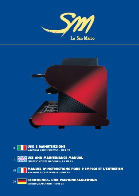
IT<br />
GB<br />
FR<br />
DE<br />
USO E MANUTENZIONE<br />
MACCHINE CAFFÈ ESPRESSO - SERIE 95<br />
USE AND MAINTENANCE MANUAL<br />
ESPRESSO COFFEE MACHINES - 95 SERIES<br />
MANUEL D’INSTRUCTIONS POUR L’EMPLOI ET L’ENTRETIEN<br />
MACHINES À CAFÉ EXPRESS - SERIE 95<br />
BEDIENUNGS- UND WARTUNGSANLEITUNG<br />
ESPRESSOMASCHINEN - SERIE 95
CENTRO ASSISTENZA AUTORIZZATO CENTRE DE SERVICE APRÈS-VENTE AGRÉÉ<br />
AUTHORIZED SERVICE CENTER AUTORISIERTER KUNDENDIENST<br />
USO E MANUTENZIONE<br />
MACCHINE CAFFÈ ESPRESSO - SERIE 95 1<br />
USE AND MAINTENANCE MANUAL<br />
ESPRESSO COFFEE MACHINES - 95 SERIES 29<br />
MANUEL D’INSTRUCTIONS POUR L’EMPLOI ET L’ENTRETIEN<br />
MACHINES À CAFÉ EXPRESS - SERIE 95 57<br />
BEDIENUNGS- UND WARTUNGSANLEITUNG<br />
ESPRESSOMASCHINEN - SERIE 95 85
INDICE<br />
RACCOMANDAZIONI (consultazione, utilizzo, garanzia) . . . . . . . . . . . . . . . . . . . . . . . . . . . . . . . . 2<br />
CARATTERISTICHE TECNICHE DEI VARI MODELLI . . . . . . . . . . . . . . . . . . . . . . . . . . . . . . . . 3<br />
CARATTERISTICHE DELLA MACCHINA . . . . . . . . . . . . . . . . . . . . . . . . . . . . . . . . . . . . . . . 4<br />
SCHEMA IDRAULICO GENERALE . . . . . . . . . . . . . . . . . . . . . . . . . . . . . . . . . . . . . . . . . . 5<br />
SCHEMA ALIMENTAZIONE IDRAULICA . . . . . . . . . . . . . . . . . . . . . . . . . . . . . . . . . . . . . . . 6<br />
LEGENDA . . . . . . . . . . . . . . . . . . . . . . . . . . . . . . . . . . . . . . . . . . . . . . . . . . . . . . . . 7<br />
PER L’INSTALLATORE<br />
INSTALLAZIONE DELLA MACCHINA . . . . . . . . . . . . . . . . . . . . . . . . . . . . . . . . . . . . . . . . 8<br />
Corredo in dotazione . . . . . . . . . . . . . . . . . . . . . . . . . . . . . . . . . . . . . . . . . . . . . . . . . . . 8<br />
Predisposizione rete idrica . . . . . . . . . . . . . . . . . . . . . . . . . . . . . . . . . . . . . . . . . . . . . . . . 8<br />
Installazione impianto idraulico . . . . . . . . . . . . . . . . . . . . . . . . . . . . . . . . . . . . . . . . . . . . . . 8<br />
Scarico . . . . . . . . . . . . . . . . . . . . . . . . . . . . . . . . . . . . . . . . . . . . . . . . . . . . . . . . . . 8<br />
Collegamento elettrico . . . . . . . . . . . . . . . . . . . . . . . . . . . . . . . . . . . . . . . . . . . . . . . . . . 9<br />
Alimentazione con Gas per riscaldamento boiler (optional). . . . . . . . . . . . . . . . . . . . . . . . . . . . . . . . . 10<br />
Carico acqua in caldaia . . . . . . . . . . . . . . . . . . . . . . . . . . . . . . . . . . . . . . . . . . . . . . . . . . 11<br />
Taratura pressione di erogazione pompa . . . . . . . . . . . . . . . . . . . . . . . . . . . . . . . . . . . . . . . . . . 11<br />
Taratura pressione acqua in caldaia . . . . . . . . . . . . . . . . . . . . . . . . . . . . . . . . . . . . . . . . . . . . 11<br />
PER L’UTENTE<br />
ISTRUZIONI PER IL FUNZIONAMENTO DELLA MACCHINA . . . . . . . . . . . . . . . . . . . . . . . . . . . . 13<br />
Riscaldamento acqua in caldaia . . . . . . . . . . . . . . . . . . . . . . . . . . . . . . . . . . . . . . . . . . . . . . 13<br />
Prelievo vapore . . . . . . . . . . . . . . . . . . . . . . . . . . . . . . . . . . . . . . . . . . . . . . . . . . . . . . 13<br />
Prelievo acqua calda (per tutti i mo<strong>de</strong>lli PRACTICAL, SPRINT e semiautomatici) . . . . . . . . . . . . . . . . . . . . 13<br />
Erogazione <strong>de</strong>l caffè (per tutti i mo<strong>de</strong>lli semiautomatici) . . . . . . . . . . . . . . . . . . . . . . . . . . . . . . . . . 13<br />
Prelievo acqua calda (per tutti i mo<strong>de</strong>lli automatici) . . . . . . . . . . . . . . . . . . . . . . . . . . . . . . . . . . . . 14<br />
Erogazione <strong>de</strong>l caffè (per tutti i mo<strong>de</strong>lli automatici) . . . . . . . . . . . . . . . . . . . . . . . . . . . . . . . . . . . . 14<br />
Erogazione <strong>de</strong>l caffè in emergenza (per mo<strong>de</strong>lli automatici 95-22) . . . . . . . . . . . . . . . . . . . . . . . . . . . . . 14<br />
NOTE AGGIUNTIVE PER MODELLI 95-26 e 95-36 . . . . . . . . . . . . . . . . . . . . . . . . . . . . . . . . . . 15<br />
NOTE AGGIUNTIVE PER MODELLI 95-23 e 95-33 . . . . . . . . . . . . . . . . . . . . . . . . . . . . . . . . . . 18<br />
NOTE AGGIUNTIVE PER MODELLI 95-31, 95-32, 95-33 e 95-36 . . . . . . . . . . . . . . . . . . . . . . . . . . . 21<br />
OPZIONI: Riscaldamento con gas . . . . . . . . . . . . . . . . . . . . . . . . . . . . . . . . . . . . . . . . . . . . 21<br />
Scaldatazze elettrico . . . . . . . . . . . . . . . . . . . . . . . . . . . . . . . . . . . . . . . . . . . . . 21<br />
Addolc<strong>it</strong>ore d’acqua . . . . . . . . . . . . . . . . . . . . . . . . . . . . . . . . . . . . . . . . . . . . . 21<br />
MANUTENZIONI ORDINARIE . . . . . . . . . . . . . . . . . . . . . . . . . . . . . . . . . . . . . . . . . . . . . 22<br />
PERIODI DI SOSTA . . . . . . . . . . . . . . . . . . . . . . . . . . . . . . . . . . . . . . . . . . . . . . . . . . . 22<br />
SITUAZIONI DI EMERGENZA . . . . . . . . . . . . . . . . . . . . . . . . . . . . . . . . . . . . . . . . . . . . . 23<br />
SEGNALAZIONE ALLARMI . . . . . . . . . . . . . . . . . . . . . . . . . . . . . . . . . . . . . . . . . . . . . . 23<br />
PRINCIPALI DIFETTI CAUSATI DA UN USO NON CORRETTO DELL’ATTREZZATURA . . . . . . . . . . . . . . 26<br />
PER IL PROGRAMMATORE<br />
PROGRAMMAZIONE DOSI PER CAFFÈ ESPRESSO E PER ACQUA CALDA . . . . . . . . . . . . . . . . . . . . 24<br />
PROGRAMMAZIONE TEMPERATURA-PRESSIONE DI LAVORO IN CALDAIA . . . . . . . . . . . . . . . . . . . 25<br />
MANUALE CODICE 7770.009<br />
Revisione 04/2006<br />
1<br />
ITALIANO
ITALIANO<br />
2<br />
RACCOMANDAZIONI<br />
CONSULTAZIONE<br />
Il presente manuale fornisce tutte le informazioni al personale ad<strong>de</strong>tto al normale uso <strong>de</strong>lla macchina e al personale tecnico adib<strong>it</strong>o alla manutenzione<br />
ordinaria, per poter operare in regime di sicurezza.<br />
Questo manuale è parte integrante <strong>de</strong>lla macchina e contiene tutte le informazioni necessarie al suo funzionamento e manutenzione.<br />
È obbligo <strong>de</strong>ll’utente leggerlo attentamente prima <strong>de</strong>ll’installazione e <strong>de</strong>ll’avviamento.<br />
Deve essere conservato per tutta la durata <strong>de</strong>lla macchina a cui si riferisce e <strong>de</strong>ve essere trasfer<strong>it</strong>o a qualsiasi altro utente o successivo proprietario.<br />
Il manuale o copia <strong>de</strong>llo stesso <strong>de</strong>v’essere sempre vicino alla macchina per consentirne la consultazione da parte <strong>de</strong>ll’operatore; va conservato<br />
in luogo protetto da calore, umid<strong>it</strong>à e agenti corrosivi.<br />
UTILIZZO<br />
Questa macchina è stata progettata per l’erogazione di caffè espresso e produzione di acqua calda per bevan<strong>de</strong> o riscaldamento indiretto di<br />
bevan<strong>de</strong>.<br />
È proib<strong>it</strong>o caricare la macchina con sostanze alcoliche.<br />
Un utilizzo <strong>de</strong>lla macchina non conforme alle prescrizioni <strong>de</strong>l presente manuale, è consi<strong>de</strong>rato contrario all’uso per cui è stata progettata la<br />
macchina facendo, di conseguenza, <strong>de</strong>ca<strong>de</strong>re ogni garanzia e sollevando <strong>La</strong> <strong>San</strong> <strong>Marco</strong> da ogni responsabil<strong>it</strong>à per eventuali danni <strong>de</strong>rivati.<br />
<strong>La</strong> macchina <strong>de</strong>ve essere azionata solo da personale che sia a conoscenza <strong>de</strong>lle sue particolari caratteristiche e che sia al corrente <strong>de</strong>lle principali<br />
procedure di sicurezza.<br />
Le regole di prevenzione <strong>de</strong>gli inci<strong>de</strong>nti ed ogni altro requis<strong>it</strong>o di sicurezza e di medicina <strong>de</strong>l lavoro <strong>de</strong>vono essere sempre osservate.<br />
Consigliamo inoltre di contattare la Casa Costruttrice per ogni necess<strong>it</strong>à di informazioni, ricambi o accessori; è fatto comunque divieto di proce<strong>de</strong>re<br />
alla realizzazione di operazioni <strong>de</strong>lle quali non si sono cap<strong>it</strong>e le esatte modal<strong>it</strong>à.<br />
Ogni modifica arb<strong>it</strong>raria apportata alla macchina ed il mancato rispetto <strong>de</strong>lle manutenzioni programmate sollevano il produttore da ogni<br />
responsabil<strong>it</strong>à per eventuali danni <strong>de</strong>rivanti.<br />
Per l’uso corretto <strong>de</strong>lla macchina è buona regola attenersi ad alcune basilari norme comportamentali quali:<br />
la manovra e l’uso <strong>de</strong>lla macchina sono riservate al solo personale ad<strong>de</strong>tto che <strong>de</strong>ve aver letto ed assimilato il contenuto di questo manuale;<br />
è obbligatorio usare un abbigliamento idoneo, come previsto dalle leggi vigenti nel Paese di utilizzo <strong>de</strong>lla macchina;<br />
non installare la macchina in locali dove sia prevista la pulizia con getti d’acqua;<br />
accertarsi che il posto di lavoro sia pul<strong>it</strong>o e in ordine e che eventuali accessori e chiavi siano al loro posto. Non eseguire nessun lavoro di pulizia<br />
o manutenzione con la tensione inser<strong>it</strong>a.<br />
È assolutamente vietato far funzionare la macchina con le protezioni fisse e/o mobili rimosse o con i dispos<strong>it</strong>ivi di sicurezza esclusi. È assolutamente<br />
vietato rimuovere o manomettere i dispos<strong>it</strong>ivi di sicurezza.<br />
Gli interventi all’impianto idraulico <strong>de</strong>vono essere esegu<strong>it</strong>i solo dal personale <strong>de</strong>l servizio assistenza tecnica e solamente dopo aver scaricato la<br />
pressione <strong>de</strong>lla caldaia (vedi MANUTENZIONI ORDINARIE).<br />
Il rispetto scrupoloso <strong>de</strong>lle manutenzioni periodiche indicate nel presente manuale è necessario sia per lavorare in sicurezza, sia per mantenere<br />
efficiente la macchina.<br />
L’eventuale riparazione <strong>de</strong>lla macchina <strong>de</strong>ve essere effettuata dalla casa costruttrice o da un centro di assistenza autorizzato<br />
LA SAN MARCO. Per la Vostra sicurezza chie<strong>de</strong>re sempre ricambi originali LA SAN MARCO. L’utilizzo di ricambi non originali fa <strong>de</strong>ca<strong>de</strong>re<br />
la garanzia e le certificazioni di conform<strong>it</strong>à che accompagnano la macchina.<br />
Per una migliore qual<strong>it</strong>à <strong>de</strong>l prodotto si raccomanda, all’avvio quotidiano <strong>de</strong>lla macchina, di proce<strong>de</strong>re alla sost<strong>it</strong>uzione <strong>de</strong>ll’acqua<br />
in caldaia ed al ricambio di quella contenuta nelle tubazioni di circolazione acqua.<br />
Nel caso in cui la macchina dovesse rimanere inattiva per diverse ore, durante l’arco <strong>de</strong>lla giornata, si raccomanda, altresì, di proce<strong>de</strong>re<br />
ad un ricambio <strong>de</strong>ll’acqua, facendola scorrere attraverso il rubinetto di prelievo acqua calda ed attraverso i gruppi di erogazione<br />
caffè.<br />
Per un corretto smaltimento <strong>de</strong>lla macchina rivolgersi alle azien<strong>de</strong> preposte alla raccolta differenziata <strong>de</strong>i rifiuti solidi.<br />
Informazione agli utenti:<br />
ai sensi <strong>de</strong>ll’art. 13 <strong>de</strong>l Decreto Legislativo 25 luglio 2005, n. 151 "Attuazione <strong>de</strong>lle Direttive 2002/95/CE, 2002/96/CE e 2003/108/CE, relative<br />
alla riduzione <strong>de</strong>ll'uso di sostanze pericolose nelle apparecchiature elettriche ed elettroniche, nonché allo smaltimento <strong>de</strong>i rifiuti"<br />
• Il simbolo <strong>de</strong>l cassonetto barrato riportato sull’apparecchiatura indica che il prodotto alla fine <strong>de</strong>lla propria v<strong>it</strong>a utile <strong>de</strong>ve<br />
essere raccolto separatamente dagli altri rifiuti.<br />
• L’utente dovrà, pertanto, conferire l’apparecchiatura giunta a fine v<strong>it</strong>a agli idonei centri di raccolta differenziata<br />
<strong>de</strong>i rifiuti elettronici ed elettrotecnici, oppure riconsegnarla al rivend<strong>it</strong>ore al momento <strong>de</strong>ll’acquisto di una nuova<br />
apparecchiatura di tipo equivalente, in ragione di uno a uno.<br />
• L’a<strong>de</strong>guata raccolta differenziata per l’avvio successivo <strong>de</strong>ll’apparecchiatura dismessa al riciclaggio, al trattamento<br />
e allo smaltimento, contribuisce ad ev<strong>it</strong>are possibili effetti negativi sull’ambiente e sulla salute e favorisce<br />
il riciclo <strong>de</strong>i materiali di cui è composta l’apparecchiatura.<br />
• Lo smaltimento abusivo <strong>de</strong>l prodotto da parte <strong>de</strong>ll’utente comporta l’applicazione <strong>de</strong>lle sanzioni amministrative di cui al<br />
D.Lgs. n. 22/1997” (articolo 50 e seguenti <strong>de</strong>l D.Lgs. n. 22/1997).<br />
GARANZIA<br />
<strong>La</strong> garanzia <strong>de</strong>ca<strong>de</strong> se:<br />
- non si rispettano le istruzioni <strong>de</strong>l presente libretto<br />
- si trascurano le manutenzioni programmate<br />
- le riparazioni sono esegu<strong>it</strong>e da personale non autorizzato<br />
- si usa la macchina in modo diverso da quello prescr<strong>it</strong>to<br />
- le parti originali sono state sost<strong>it</strong>u<strong>it</strong>e con pezzi di altra fabbricazione.<br />
Controllare la macchina al momento <strong>de</strong>lla consegna per verificare eventuali danni da trasporto.<br />
Eventuali reclami <strong>de</strong>vono essere inoltrati a LA SAN MARCO per iscr<strong>it</strong>to entro 8 giorni dalla ricezione.<br />
ATTENZIONE<br />
Si raccomanda di conservare tutta la documentazione tecnica compreso lo schema elettrico allegato al presente manuale.<br />
LA SAN MARCO si riserva di applicare modifiche tecniche alla macchina qualora lo r<strong>it</strong>enesse necessario senza preavviso.
SEMIAUTOMATICHE<br />
AUTOMATICHE<br />
MODELLO<br />
CARATTERISTICHE TECNICHE<br />
DEI VARI MODELLI<br />
N°<br />
GRUPPI<br />
CAPACITÀ<br />
CALDAIA<br />
(l<strong>it</strong>ri)<br />
POTENZA ASSORBITA (W)<br />
COLL. ALLA RETE<br />
MONOF. TRIFASE<br />
MOTORE<br />
POMPA<br />
SCALDA-<br />
TAZZE<br />
(Optional)<br />
PESO<br />
(kg)<br />
DIMENS.<br />
A<br />
(mm)<br />
95-PRACT-S 1 2,5 2000 – 275 – 41 360<br />
95-SPRINT-S 2 4,9 3000 4500 275 – 56 605<br />
95-21<br />
95-31<br />
95-PRACT-E 1 2,5 2000 – 275 – 42 360<br />
95-SPRINT-E 2 4,9 3000 4500 275 – 56 605<br />
95-22<br />
95-32<br />
95-23 2 12<br />
95-33 3 19<br />
95-26<br />
95-36<br />
2 12<br />
3500<br />
4500<br />
3500<br />
4500<br />
3 19<br />
5500<br />
7000<br />
5500<br />
7000<br />
4 25 7000<br />
7000<br />
9000<br />
2 12<br />
3 19<br />
3500<br />
4500<br />
5500<br />
7000<br />
4 25 7000<br />
2 12<br />
3 19<br />
3500<br />
4500<br />
3500 3500<br />
4500 4500<br />
5500 5500<br />
7000 7000<br />
3500<br />
4500<br />
5500<br />
7000<br />
4 25 7000<br />
• Le macchine sono predisposte per le<br />
seguenti tensioni:<br />
400V - 3N trifase (resistenze )<br />
230V - 3 trifase (resistenze )<br />
230V monofase<br />
• I mo<strong>de</strong>lli PRACTICAL solamente<br />
110/230V monofase.<br />
• Pompa interna nei mo<strong>de</strong>lli<br />
PRACTICAL e SPRINT.<br />
Pompa esterna nei rimanenti<br />
mo<strong>de</strong>lli (interna solo a richiesta).<br />
5500<br />
7000<br />
7000<br />
9000<br />
3500<br />
4500<br />
5500<br />
7000<br />
7000<br />
9000<br />
300 100 56 695<br />
300 125 70 935<br />
300 150 90 1170<br />
300 100 60 695<br />
300 125 74 935<br />
300 150 94 1170<br />
300 100 60 695<br />
300 125 74 935<br />
300 100 60 695<br />
300 125 74 935<br />
300 150 94 1170<br />
CARATTERISTICHE FUNZIONALI<br />
1 • Erogazione caffè con avvio ed arresto tram<strong>it</strong>e<br />
pulsante.<br />
• Prelievo acqua calda e vapore su tutti i mo<strong>de</strong>lli.<br />
• Autolivello (caricamento automatico acqua<br />
in caldaia) per tutti i mo<strong>de</strong>lli.<br />
2 • 95-21: Versione normale.<br />
• 95-31: Versione a temperatura stabilizzata.<br />
3 • Erogazione caffè a dosaggio elettronico con<br />
possibil<strong>it</strong>à di memorizzare 6 dosi diverse per<br />
ogni gruppo.<br />
• Prelievo acqua calda e vapore su tutti i mo<strong>de</strong>lli,<br />
con possibil<strong>it</strong>à (esclusi i mo<strong>de</strong>lli<br />
PRACTICAL e SPRINT) di memorizzare 2<br />
dosi diverse di acqua calda.<br />
• Autolivello (caricamento automatico acqua<br />
in caldaia) per tutti i mo<strong>de</strong>lli.<br />
• Funzionamento in semiautomatico (fino max<br />
2 gruppi) in caso di avaria <strong>de</strong>l sistema elettronico<br />
(esclusi i mo<strong>de</strong>lli PRACTICAL/<br />
SPRINT).<br />
4 • 95-22: Versione normale.<br />
• 95-32: Versione a temperatura stabilizzata.<br />
5 • Come punto 3, più predisposizione per il<br />
collegamento con sistemi centralizzati di<br />
gestione camerieri (Walla, Hartwall).<br />
6 • 95-23: Versione normale.<br />
• 95-33: Versione a temperatura stabilizzata.<br />
7 • Come punto 3, più display con segnalazione<br />
temperatura/pressione caldaia e numero<br />
caffè erogati per singola dose.<br />
• Programmazione esterna <strong>de</strong>lle temperature<br />
di esercizio.<br />
• Possibil<strong>it</strong>à di programmare accensione e<br />
spegnimento automatico <strong>de</strong>lla macchina.<br />
• Display con indicazione: ore, minuti e giorno<br />
<strong>de</strong>lla settimana. Allarme per rigenerazione<br />
<strong>de</strong>puratore con barra luminosa (ver<strong>de</strong>gialla-rossa).<br />
8 • 95-26: Versione normale.<br />
• 95-36: Versione a temperatura stabilizzata.<br />
In opzione :<br />
• Scaldatazze elettrico per tutti i mo<strong>de</strong>lli<br />
(esclusi PRACTICAL e SPRINT).<br />
• Addolc<strong>it</strong>ore per tutti i mo<strong>de</strong>lli.<br />
• Impianto di riscaldamento a gas<br />
solo per i mo<strong>de</strong>lli :<br />
95-21 95-22 95-31 95-32.<br />
3<br />
ITALIANO
ITALIANO<br />
4<br />
MOD. AUTOMATICO<br />
CARATTERISTICHE<br />
DELLA MACCHINA<br />
MOD. SEMIAUTOMATICO
SCHEMA<br />
IDRAULICO GENERALE<br />
Versione a temperatura stabilizzata<br />
Versione normale<br />
5<br />
ITALIANO
ITALIANO<br />
Collegamento per mo<strong>de</strong>lli<br />
con pompa interna<br />
6<br />
SCHEMA<br />
ALIMENTAZIONE IDRAULICA<br />
Collegamento per mo<strong>de</strong>lli<br />
con pompa esterna
1 Piatto raccogli fondi con griglia<br />
2 Rubinetto autolivello<br />
3 Rubinetto autolivello<br />
4 Rubinetto scarico caldaia<br />
5 Rubinetto per contatori volumetrici<br />
6 Rubinetto per contatori volumetrici<br />
7 Contatori volumetrici<br />
8 Vaschetta raccogli fondi<br />
9 Valvola di r<strong>it</strong>egno<br />
10 Valvola di r<strong>it</strong>egno e sicurezza<br />
11 Elettrovalvola per autolivello con filtro<br />
12 Nipple 3/8” (alimentazione macchina)<br />
13 Nipple 3/8” (rubinetto rete idrica)<br />
14 Dado 3/8”<br />
15 Rubinetto alimentazione rete idrica<br />
16 Tubo alimentazione rete idrica<br />
17 Nipple 3/8” (aspirazione pompa)<br />
17a Nipple 3/8” (mandata pompa)<br />
18 Tubo alimentazione macchina<br />
19 Tubo alimentazione addolc<strong>it</strong>ore<br />
20 Tubo scarico acqua<br />
21 Pompa<br />
22 V<strong>it</strong>e di regolazione pressione pompa<br />
23 Rubinetto addolc<strong>it</strong>ore superiore<br />
24 Rubinetto addolc<strong>it</strong>ore inferiore<br />
25 Tubo alimentazione pompa<br />
26 Addolc<strong>it</strong>ore<br />
27 Valvola a pulsante<br />
28 Pulsante per valvola<br />
29 Rubinetto prelievo vapore<br />
30 Interruttore generale<br />
31 Livello ottico<br />
32 Pulsante erogazione manuale<br />
33 Pulsante erogazione continua<br />
34 Pulsante selezione caffè singolo ristretto<br />
35 Pulsante selezione caffè singolo medio<br />
36 Pulsante selezione caffè singolo lungo<br />
37 Pulsante selezione caffè doppio ristretto<br />
38 Pulsante selezione caffè doppio medio<br />
39 Pulsante selezione caffè doppio lungo<br />
40 Pulsante prelievo continuo di acqua<br />
41 Pulsante prelievo automatico acqua<br />
42 Pulsante prelievo automatico acqua<br />
43 Pulsante (a fianco <strong>de</strong>l display)<br />
44a Manometro pressione caldaia<br />
44b Manometro pressione pompa<br />
LEGENDA<br />
45<br />
46<br />
47<br />
48<br />
49<br />
50<br />
51<br />
52<br />
53<br />
54<br />
55<br />
56<br />
57<br />
58<br />
59<br />
60<br />
61<br />
62<br />
63<br />
64<br />
65<br />
73<br />
74<br />
75<br />
76<br />
77<br />
78<br />
79<br />
80<br />
81<br />
82<br />
83<br />
84<br />
85<br />
86<br />
87<br />
88<br />
91<br />
92<br />
A<br />
B<br />
C<br />
D<br />
E<br />
Pressostato<br />
V<strong>it</strong>e taratura pressione<br />
Fiancata<br />
Display<br />
Rubinetto gas<br />
Bruciatore gas<br />
Pulsante di sicurezza gas<br />
Sonda termica per gas<br />
Pulsante accensione automatica gas<br />
Foro spia fiamma<br />
Valvola miscela aria-gas<br />
Gicleur gas<br />
V<strong>it</strong>e di regolazione fiamma<br />
V<strong>it</strong>e di regolazione fiamma<br />
Rubinetto prelievo acqua calda<br />
Pulsante scaldatazze elettrico<br />
Tubo prelievo acqua calda<br />
Interruttore esclusione dosatura automatica<br />
Interruttore dosatura manuale 1° gruppo<br />
Interruttore dosatura manuale 2° gruppo<br />
Spia contatori volumetrici<br />
Fusibili<br />
Centralina elettronica<br />
Termostato di sicurezza<br />
Caldaia<br />
Resistenze elettriche<br />
Scambiatore termico<br />
Valvola antivuoto<br />
Valvola di sicurezza<br />
Sonda temperatura acqua<br />
Sonda livello acqua<br />
Sonda termostato<br />
Elettrovalvola prelievo acqua calda<br />
Elettrovalvola erogazione caffè<br />
Coppa portafiltro<br />
Vaschetta raccogli gocce<br />
Infusore<br />
Pannello con display e pulsantiera<br />
Tubicino di raf<strong>fr</strong>eddamento<br />
Leva per rubinetto 23<br />
Tubo di scarico<br />
Leva per rubinetto 24<br />
Tubo di scarico<br />
Pomello apertura coperchio addolc<strong>it</strong>ore<br />
7<br />
ITALIANO
ITALIANO<br />
INSTALLAZIONE DELLA MACCHINA<br />
<strong>La</strong> macchina viene consegnata imballata; dopo aver tolto l’imballo assicurarsi <strong>de</strong>ll’integr<strong>it</strong>à <strong>de</strong>lla stessa, in caso di dubbio non<br />
utilizzare la macchina e rivolgersi a personale qualificato e autorizzato <strong>La</strong> <strong>San</strong> <strong>Marco</strong> S.p.A.<br />
L’imballo dovrà essere smalt<strong>it</strong>o presso gli appos<strong>it</strong>i centri di raccolta separando il legno dal polistirolo e dal nylon, come previsto<br />
dalle leggi vigenti nel paese di utilizzo <strong>de</strong>lla macchina; <strong>de</strong>tto materiale non <strong>de</strong>ve essere lasciato alla portata <strong>de</strong>i bambini in<br />
quanto fonte di pericolo. <strong>La</strong> macchina <strong>de</strong>ve essere posta su un piano perfettamente orizzontale e sufficientemente robusto per<br />
sostenere il peso <strong>de</strong>lla stessa, con uno spazio attorno sufficiente al fine di smaltire il calore prodotto durante il funzionamento.<br />
CORREDO IN DOTAZIONE<br />
Nell’imballo <strong>de</strong>lla macchina è inser<strong>it</strong>o il corredo, il quale è composto da:<br />
- coppe portafiltro con anello fermafiltro<br />
- filtri e beccucci per dosi singole e doppie<br />
- filtro cieco<br />
- pressino per caffè<br />
- tubo di scarico flessibile in gomma e spirale in acciaio<br />
- tubi di alimentazione in gomma per alimenti, trecciati in inox<br />
- nipple da 3/8” per allacciamento alla rete<br />
- spazzolino per pulizia sottocoppe<br />
Il completamento di serie <strong>de</strong>ll’impianto è cost<strong>it</strong>u<strong>it</strong>o dal motore pompa forn<strong>it</strong>o con l’imballo a parte. Se richiesto viene aggiunto<br />
come optional l’addolc<strong>it</strong>ore manuale o automatico per la <strong>de</strong>calcificazione <strong>de</strong>ll’acqua di alimentazione.<br />
Si raccomanda, prima di collegare l’addolc<strong>it</strong>ore alla macchina, di provve<strong>de</strong>re al lavaggio <strong>de</strong>lle resine in esso contenute, operando<br />
nella seguente maniera:<br />
1 Collegare con il tubo 19, trecciato inox da 900 mm, la valvola generale di servizio 15 al rubinetto, 23, di entrata acqua<br />
all’addolc<strong>it</strong>ore 26<br />
2. Collegare il rubinetto 24 <strong>de</strong>ll’addolc<strong>it</strong>ore 26 alla rete di smaltimento <strong>de</strong>lle acque bianche<br />
3. Aprire i rubinetti 23 e 24 e far scorrere, per circa 15 minuti, acqua attraverso l’addolc<strong>it</strong>ore.<br />
L’addolc<strong>it</strong>ore è consi<strong>de</strong>rato un’apparecchiatura indispensabile per il buon funzionamento <strong>de</strong>lla macchina; se l’utilizzatore<br />
non ha previsto nessun sistema di <strong>de</strong>calcificazione, è opportuno provve<strong>de</strong>rvi per garantire l’efficienza <strong>de</strong>lla macchina.<br />
PREDISPOSIZIONE RETE IDRICA<br />
Alimentazione<br />
Portare ai piedi <strong>de</strong>lla macchina il tubo <strong>de</strong>lla rete idrica (almeno da 3/8”) e montare una valvola di intercettazione, preferibilmente<br />
a sfera da 3/8”, che permetta una rapida manovra di apertura e chiusura.<br />
Scarico<br />
A piano pavimento preve<strong>de</strong>re un pozzetto ispezionabile collegato con la rete di smaltimento <strong>de</strong>lle acque bianche, atto ad accogliere<br />
il tubo di scarico <strong>de</strong>lla macchina per grav<strong>it</strong>à. Il tubo di scarico <strong>de</strong>ve essere posizionato in modo che l’efflusso sia libero e<br />
per ev<strong>it</strong>are l’intasamento da accumulo di fondi caffè durante l’esercizio.<br />
INSTALLAZIONE IMPIANTO IDRAULICO<br />
a) Montare sulla valvola generale di servizio 15 il nipple da 3/8” 13.<br />
b) Collegare con il tubo in gomma trecciato inox (da 900 mm) 19 la valvola generale di servizio 15 al rubinetto 23 di entrata<br />
acqua all’addolc<strong>it</strong>ore 26.<br />
c) Collegare con il tubo in gomma trecciato inox (da 600 mm) 25 il nipple 17 (aspirazione <strong>de</strong>lla pompa 21), al rubinetto 24 <strong>de</strong>ll’addolc<strong>it</strong>ore<br />
26.<br />
d) Collegare con il tubo in gomma trecciato inox (da 1600 mm) 18 il nipple 17a (mandata <strong>de</strong>lla pompa 21), al nipple 12 di<br />
ingresso acqua nella macchina.<br />
Note: nei mo<strong>de</strong>lli Practical e Sprint, il tubo in gomma 18 (da 2500 mm) collega direttamente il rubinetto 24 <strong>de</strong>ll’addolc<strong>it</strong>ore con l’aspirazione<br />
<strong>de</strong>lla pompa 21 incorporata all’interno <strong>de</strong>lla macchina. Per l’installazione <strong>de</strong>ll’addolc<strong>it</strong>ore rispettare le relative istruzioni.<br />
SCARICO<br />
Allacciare il tubo di scarico 20 alla vaschetta raccogli fondi 8 e collegarlo al pozzetto di scarico <strong>de</strong>lla rete di smaltimento<br />
acque.<br />
8<br />
PER L’INSTALLATORE
COLLEGAMENTO ELETTRICO<br />
a) All’atto <strong>de</strong>ll’installazione, prima di collegare la macchina, accertarsi che i dati di targa siano rispon<strong>de</strong>nti a quelli <strong>de</strong>lla rete di<br />
distribuzione elettrica; la targa è sistemata sulla parte lavoro <strong>de</strong>lla macchina. L’installazione <strong>de</strong>ve essere effettuata in ottemperanza<br />
alle norme di sicurezza vigenti, secondo le indicazioni <strong>de</strong>l costruttore o personale autorizzato LA SAN MARCO.<br />
Un’errata installazione può causare danni a persone o cose per le quali il costruttore non può essere consi<strong>de</strong>rato responsabile.<br />
Prima di proce<strong>de</strong>re al collegamento elettrico <strong>de</strong>lla macchina è necessario far verificare da tecnici qualificati che la rete sia<br />
dotata di un efficace impianto di messa a terra. L’efficacia di questo impianto è prior<strong>it</strong>aria per la messa in sicurezza <strong>de</strong>lla<br />
macchina.<br />
Nel caso si ren<strong>de</strong>sse necessario l’uso di adattatori, prese multiple e/o prolunghe, è necessario utilizzare solamente prodotti<br />
conformi alle norme di sicurezza vigenti.<br />
Per ev<strong>it</strong>are eventuali surriscaldamenti <strong>de</strong>l cavo di alimentazione si raccomanda di svolgerlo per tutta la sua lunghezza.<br />
Nell’eventual<strong>it</strong>à che il cavo <strong>de</strong>bba essere sost<strong>it</strong>u<strong>it</strong>o o si danneggi, spegnere la macchina e rivolgersi a personale LA SAN<br />
MARCO per la sua sost<strong>it</strong>uzione. A monte <strong>de</strong>ll’impianto elettrico di alimentazione è consigliabile installare un interruttore<br />
generale onnipolare, il quale <strong>de</strong>ve essere dimensionato secondo le caratteristiche elettriche (potenza e tensione) riportate<br />
sulla targa <strong>de</strong>lla macchina; <strong>de</strong>tto interruttore <strong>de</strong>ve disinserirsi dalla rete con una apertura <strong>de</strong>i contatti di almeno 3 mm.<br />
b) Se la macchina è dotata di pompa esterna, eseguire il collegamento con il cavo relativo.<br />
c) Collegare il cavo di alimentazione all’interruttore generale, prece<strong>de</strong>ntemente installato, nel seguente modo:<br />
SOLO PER<br />
MODELLI<br />
PRACTICAL<br />
SOLO PER<br />
MODELLI<br />
SPRINT<br />
RIMANENTI<br />
MODELLI<br />
NOTE:<br />
Collegamento a non<br />
possibile per il mod.<br />
95-26.<br />
* <strong>La</strong> potenza assorb<strong>it</strong>a<br />
<strong>de</strong>lle resistenze<br />
elettriche può essere<br />
ridotta a 2/3 eliminando<br />
uno <strong>de</strong>i due<br />
fili NERI.<br />
110V/230V MONOFASE<br />
BLU<br />
MARRONE<br />
GI/VE<br />
230V MONOFASE<br />
BLU<br />
NERO<br />
NERO<br />
MARRONE<br />
GI/VE<br />
400V-3N TRIFASE<br />
BLU<br />
NERO<br />
NERO<br />
MARRONE<br />
GI/VE<br />
230V-3 TRIFASE<br />
BLU<br />
NERO<br />
NERO<br />
MARRONE<br />
GI/VE<br />
230V MONOFASE * 400V-3N TRIFASE<br />
BLU<br />
NERO<br />
NERO<br />
MARRONE<br />
GI/VE<br />
230V-3 TRIFASE<br />
BLU<br />
NERO<br />
NERO<br />
MARRONE<br />
GI/VE<br />
PER L’INSTALLATORE<br />
BLU<br />
NERO<br />
NERO<br />
MARRONE<br />
GI/VE<br />
1 RESISTENZA<br />
BLU<br />
MARRONE<br />
GI/VE<br />
2 RESISTENZE<br />
NERO<br />
NERO<br />
MARRONE<br />
BLU<br />
GI/VE<br />
3 RESISTENZE<br />
BLU<br />
NERO<br />
MARRONE<br />
NERO<br />
GI/VE<br />
3 RESISTENZE<br />
BLU<br />
MARRONE<br />
NERO<br />
NERO<br />
GI/VE<br />
3 RESISTENZE<br />
BLU<br />
NERO<br />
NERO<br />
MARRONE<br />
GI/VE<br />
3 RESISTENZE<br />
BLU<br />
NERO<br />
MARRONE<br />
NERO<br />
GI/VE<br />
9<br />
ITALIANO
ITALIANO<br />
Alimentazione con Gas per riscaldamento boiler (optional).<br />
Leggere le istruzioni prima di installare e usare l'apparecchio.<br />
ATTENZIONE<br />
Questo apparecchio può essere installato e funzionare solo in locali permanentemente ventilati secondo le Norme UNI-CIG<br />
7129 e UNI-CIG 7131.<br />
Collegamento alla rete di distribuzione gas<br />
Collocate l'apparecchiatura secondo le istruzioni contenute nel libretto uso e manutenzione, rimuovete il piatto raccogli fondi<br />
con griglia e proce<strong>de</strong>te al collegamento alla rete di distribuzione gas, o bombola GPL (G30/G31), impiegando tubi metallici<br />
rigidi oppure tubi metallici flessibili conformi alla Norma UNI-CIG 9891.<br />
Verificate che la predisposizione gas <strong>de</strong>ll'apparecchio, rilevabile sull'appos<strong>it</strong>a targhetta di taratura, corrisponda al gas effettivamente<br />
disponibile. Nel caso di mancata corrispon<strong>de</strong>nza, proce<strong>de</strong>te al cambio di predisposizione come <strong>de</strong>scr<strong>it</strong>to nel paragrafo<br />
"cambio taratura".<br />
<strong>La</strong> rampa d'ingresso alimentazione gas, cost<strong>it</strong>u<strong>it</strong>a dal rubinetto d'intercettazione <strong>de</strong>ll'apparecchiatura (51), è una filettatura<br />
secondo Norma ISO 228-1 (non a tenuta sul filetto) G 1/8".<br />
Nel caso di utilizzo per il collegamento alla rete di tubi metallici rigidi, interponete appropriata ogiva <strong>fr</strong>a il rubinetto ed il tubo<br />
metallico rigido sul quale, a sua volta, va collocata una filettatura femmina secondo Norma ISO 228-1 (non a tenuta sul filetto)<br />
G 1/8".<br />
Nel caso di utilizzo per il collegamento alla rete di tubi metallici flessibili, interponete appropriato nipple femmina secondo la<br />
Norma ISO 7-1 (a tenuta sul filetto) G 1/8" e maschio secondo Norma ISO 228-1 (non a tenuta sul filetto) G 1/2", sulla cui<br />
se<strong>de</strong> andrà collocata un’appos<strong>it</strong>a guarnizione di tenuta.<br />
A collegamento effettuato, apr<strong>it</strong>e l'alimentazione gas a monte <strong>de</strong>ll'apparecchiatura e con una soluzione saponosa (mai una fiamma<br />
libera), verificate la perfetta tenuta <strong>de</strong>l collegamento.<br />
Scarico <strong>de</strong>i prodotti <strong>de</strong>lla combustione<br />
L'apparecchiatura, in relazione allo scarico <strong>de</strong>i prodotti <strong>de</strong>lla combustione, è di Tipo A1; ovvero preleva l'aria comburente<br />
necessaria alla combustione dall'ambiente e scarica i fumi nel me<strong>de</strong>simo.<br />
Ponete particolare attenzione al volume <strong>de</strong>ll'ambiente nel quale inten<strong>de</strong>te posizionare l'apparecchiatura, che <strong>de</strong>ve essere almeno<br />
pari a 12 m 3.<br />
Nel caso il volume fosse inferiore, sarà necessario posizionare l'apparecchiatura direttamente sotto una cappa aspirante realizzando,<br />
anche, una presa di ventilazione per l'adduzione <strong>de</strong>ll'aria comburente la cui sezione di passaggio utile non <strong>de</strong>ve essere<br />
inferiore a 100 cm 2.<br />
Accensione<br />
Premete e ruotate il pomello <strong>de</strong>l rubinetto gas (51) in senso antiorario fino al simbolo raffigurante una fiamma, come indicato<br />
in Fig. B; mantenendo premuta la manopola, ag<strong>it</strong>e sul tasto preposto all'accensione e contraddistinto dal simbolo raffigurante<br />
una stella (53) premendolo più volte fino all'accensione <strong>de</strong>l bruciatore (accensione piezoelettrica).<br />
Ad accensione avvenuta, verificabile attraverso le appos<strong>it</strong>e fer<strong>it</strong>oie (54), mantenete premuta la manopola <strong>de</strong>l rubinetto gas per<br />
5/10 sec. Dopo tale periodo, se la fiamma non dovesse rimanere accesa, ripetete l'operazione sopra <strong>de</strong>scr<strong>it</strong>ta.<br />
Cambio taratura<br />
L'apparecchiatura è predisposta per funzionare con il gas indicato nell'appos<strong>it</strong>a targhetta di taratura rilevabile sull'apparecchiatura.<br />
Le indicazioni relative alla regolazione aria, iniettore, Portata termica nominale e ridotta,sono rilevabili nelle Tabelle 1 e 2.<br />
<strong>La</strong> corrispon<strong>de</strong>nza di tali dati con ciascun mo<strong>de</strong>llo, è rilevabile dal penultimo carattere <strong>de</strong>lla sigla <strong>de</strong>l mo<strong>de</strong>llo stesso.<br />
Ad esempio, la sigla mo<strong>de</strong>llo rilevabile sulla targa caratteristica parte gas 95-21-3 gr. riporta, al penultimo carattere il numero 3.<br />
Bisognerà quindi, in questo caso, riferirsi ai dati riportati rispettivamente nelle Tabelle 1 e 2, alla colonna <strong>de</strong>nominata "3 Gruppi ".<br />
Nel caso si dovesse proce<strong>de</strong>re al cambio taratura <strong>de</strong>ll'apparecchiatura, segu<strong>it</strong>e le indicazioni di segu<strong>it</strong>o riportate.<br />
Sv<strong>it</strong>ate la v<strong>it</strong>e <strong>de</strong>lla ghiera registrazione aria primaria (55 - Fig. C), scoprendo l'ugello (56). Con appos<strong>it</strong>a chiave sv<strong>it</strong>ate l'ugello<br />
(56) sost<strong>it</strong>uendolo con quello appropriato indicato in Tabella 2, verificando la corrispon<strong>de</strong>nza <strong>de</strong>l diametro <strong>de</strong>l me<strong>de</strong>simo<br />
sul corpo <strong>de</strong>ll’ugello stesso.<br />
Avv<strong>it</strong>ate il nuovo ugello (56) e, sub<strong>it</strong>o dopo, posizionate la ghiera registrazione aria primaria (55 - Fig. C) secondo quanto indicato<br />
in Tabella 1, utilizzando per la registrazione <strong>de</strong>lla quota "L" un calibro o strumento equivalente ben avv<strong>it</strong>ando la v<strong>it</strong>e preposta<br />
al blocco <strong>de</strong>l me<strong>de</strong>simo.<br />
Commutate l’interruttore generale (30) nella posizione 1, in modo da inserire una sola resistenza (50% <strong>de</strong>lla potenza elettrica<br />
<strong>de</strong>l boiler per resistenza monofase a 2 elementi e 1/3 <strong>de</strong>lla potenza per resistenze a 3 elementi con collegamento trifase) ed<br />
accen<strong>de</strong>te il bruciatore come già <strong>de</strong>scr<strong>it</strong>to. Appena la temperatura <strong>de</strong>ll'acqua contenuta nel boiler avrà raggiunto la temperatura<br />
impostata, il regolatore di portata <strong>de</strong>l gas ridurrà automaticamente la portata me<strong>de</strong>sima al valore corrispon<strong>de</strong>nte alla portata termica<br />
nominale ridotta.<br />
A questo punto ag<strong>it</strong>e sulla v<strong>it</strong>e (58) <strong>de</strong>l regolatore di portata, al fine di ottimizzare la fiamma dal punto di vista <strong>de</strong>lla stabil<strong>it</strong>à e<br />
che lambisca l'elemento sensibile <strong>de</strong>lla termocoppia preposto alla rilevazione di fiamma (52) e sulla v<strong>it</strong>e (57) per ottenere il<br />
valore di pressione massima <strong>de</strong>si<strong>de</strong>rata nel boiler.<br />
10<br />
ISTRUZIONI PER L’INSTALLATORE AUTORIZZATO
Gas<br />
GPL (G30/G31)<br />
Metano (G20)<br />
ISTRUZIONI PER L’INSTALLATORE AUTORIZZATO<br />
1° GRUPPO 2° GRUPPO<br />
Tabella 1 - Regolazione aria primaria<br />
2 GRUPPI<br />
L = 8 mm<br />
L = 4 mm<br />
3 GRUPPI<br />
L = 10 mm<br />
L = 4 mm<br />
Qnr = Portata termica nominale<br />
Qnr = Portata termica nominale ridotta<br />
4 GRUPPI<br />
L = 12 mm<br />
L = 4 mm<br />
Tabella 2 - Diametro ugelli in 100/mm<br />
Gas<br />
GPL (G30/G31)<br />
Metano (G20)<br />
Qn (kW)<br />
Qnr (kW)<br />
2 GRUPPI<br />
40<br />
60 X<br />
0,75<br />
N.A.<br />
3 GRUPPI<br />
55<br />
81 X<br />
1,45<br />
1,0<br />
4 GRUPPI<br />
65<br />
90 X<br />
1,9<br />
1,3<br />
Verificato il buon funzionamento, sost<strong>it</strong>u<strong>it</strong>e la targhetta di taratura <strong>de</strong>ll'apparecchio con quella corrispon<strong>de</strong>nte al nuovo gas che<br />
trovate abbinata al k<strong>it</strong> forn<strong>it</strong>o di serie, contenente l'ugello appena montato.<br />
Dispos<strong>it</strong>ivi di sicurezza presenti (a riarmo manuale)<br />
L'apparecchiatura è dotata di due dispos<strong>it</strong>ivi di sicurezza che bloccano l'erogazione <strong>de</strong>l gas nel caso di spegnimento acci<strong>de</strong>ntale<br />
<strong>de</strong>lla fiamma..<br />
1 - Termocoppia (52):<br />
agisce sul rubinetto (51) la cui sonda (52) <strong>de</strong>ve essere lamb<strong>it</strong>a dalla fiamma <strong>de</strong>l bruciatore (50); in caso contrario l'erogazione<br />
<strong>de</strong>l gas verrà automaticamente bloccata.<br />
2 - Termostato (59):<br />
posto a contatto <strong>de</strong>l boiler, agisce sul rubinetto (51); alla temperatura di 140 °C rilevata dall'elemento sensibile <strong>de</strong>l termostato<br />
(59) sul corpo boiler, l'erogazione <strong>de</strong>l gas verrà automaticamente bloccata.<br />
Solamente dopo il raf<strong>fr</strong>eddamento <strong>de</strong>l corpo boiler a 110 °C, sarà possibile riaccen<strong>de</strong>re il bruciatore con la procedura già<br />
<strong>de</strong>scr<strong>it</strong>ta.<br />
Successivamente all'intervento di una <strong>de</strong>lle due sicurezze, tentate di riaccen<strong>de</strong>re il bruciatore come già prece<strong>de</strong>ntemente<br />
<strong>de</strong>scr<strong>it</strong>to.<br />
ATTENZIONE<br />
Se il mal funzionamento, con conseguente spegnimento <strong>de</strong>l bruciatore, dovesse persistere, contattate il Servizio<br />
di assistenza autorizzato a Voi più vicino, che provve<strong>de</strong>rà ad eliminare la causa <strong>de</strong>l blocco.<br />
Fig.C<br />
L<br />
55<br />
59<br />
55<br />
52<br />
56<br />
57<br />
50<br />
58<br />
Fig.A Fig.B<br />
SPENTO ACCESO<br />
51<br />
DALLA RETE GAS<br />
53<br />
11<br />
ITALIANO
ITALIANO<br />
Versione con sonda sistemata<br />
sul coperchio <strong>de</strong>lla caldaia<br />
+<br />
12<br />
– –<br />
+<br />
PER L’INSTALLATORE<br />
Prima di mettere in funzione la macchina controllare l’integr<strong>it</strong>à ed il perfetto funzionamento <strong>de</strong>i dispos<strong>it</strong>ivi di sicurezza. Prima<br />
di iniziare il lavoro è necessario familiarizzare con i comandi <strong>de</strong>lla macchina, ponendo particolare attenzione ai pulsanti ed alle<br />
procedure d’emergenza, seguendo le istruzioni <strong>de</strong>l presente manuale.<br />
Non sottoporre la macchina a prestazioni superiori a quanto prescr<strong>it</strong>to.<br />
CARICO ACQUA IN CALDAIA<br />
Controllo posizione rubinetti impianto idrico<br />
a) Togliere il piatto raccogli fondi con relativa griglia 1 e controllare:<br />
- Rubinetto scarico caldaia 4 chiuso<br />
- Rubinetto valvola autolivello 2 aperto<br />
- Rubinetto valvola autolivello 3 aperto<br />
- Rubinetti per contatori volumetrici 6 aperti<br />
b) Riposizionare piatto raccogli fondi con relativa griglia.<br />
c) Aprire rubinetto 15 di alimentazione generale <strong>de</strong>ll’acqua.<br />
d) Aprire un rubinetto vaporizzatore 29 per permettere la fuoriusc<strong>it</strong>a <strong>de</strong>ll’aria in fase di riempimento caldaia.<br />
Solo per mo<strong>de</strong>lli PRACTICAL e SPRINT<br />
e) Portare l’interruttore generale 30 su posizione 1 in modo da eseguire il carico automatico <strong>de</strong>lla caldaia con esclusione <strong>de</strong>lle<br />
resistenze. Quando l’acqua raggiunge la sonda si illumerà il led contrassegnato “MAX”.<br />
f) Concluso il caricamento di acqua in caldaia commutare l’interruttore generale da posizione 1 a posizione 2 di lavoro.<br />
Rimanenti mo<strong>de</strong>lli<br />
g) Controllare che l’interruttore generale 30 si trovi sulla posizione “zero”.<br />
h) Tenere premuta la leva 28 fino a quando l’acqua non avrà raggiunto i 3/4 <strong>de</strong>l livello ottico 31.<br />
Regolazione livello acqua<br />
Questa regolazione viene esegu<strong>it</strong>a in fabbrica. Se richiesto, la regolazione si effettua posizionando la sonda come indicato<br />
nelle figure che seguono:<br />
Versione con sonda sistemata nella<br />
parte superiore <strong>de</strong>lla caldaia<br />
TARATURA PRESSIONE DI EROGAZIONE POMPA<br />
a) Una volta riemp<strong>it</strong>a la caldaia portare l’interruttore generale in posizione 2 (le resistenze inziano a riscaldare l’acqua).<br />
b) Azionare il pulsante di erogazione continua 32 per le macchine a dosatura manuale o il pulsante 33 per le macchine elettroniche<br />
a dosatura automatica, in modo che l’acqua fuoriesca dal gruppo corrispon<strong>de</strong>nte al pulsante azionato.<br />
c) Leggere sulla scala inferiore <strong>de</strong>l manometro 44 il valore <strong>de</strong>lla pressione <strong>de</strong>ll’acqua. Il valore di taratura ottimale è di 9 bar.<br />
<strong>La</strong> regolazione <strong>de</strong>lla pressione al valore <strong>de</strong>si<strong>de</strong>rato si ottiene agendo sulla v<strong>it</strong>e 22 <strong>de</strong>lla pompa; avv<strong>it</strong>ando si aumenta la pressione,<br />
mentre sv<strong>it</strong>ando si diminuisce. Come indicato nella figura che<br />
segue, in funzione <strong>de</strong>l mo<strong>de</strong>llo di pompa in dotazione alla macchina,<br />
esistono tre casi diversi per la regolazione di <strong>de</strong>tta v<strong>it</strong>e:<br />
- regolare solamente la v<strong>it</strong>e<br />
- regolare la v<strong>it</strong>e e bloccare con dado<br />
- sv<strong>it</strong>are il dado cieco di protezione e regolare la v<strong>it</strong>e.<br />
TARATURA PRESSIONE ACQUA IN CALDAIA<br />
a) Concluso il carico acqua in caldaia portare l’interruttore generale nella<br />
posizione 2 (le resistenze elettriche iniziano a riscaldare l’acqua).<br />
b) Aprire un rubinetto vaporizzatore a leva 29 in modo che in fase di<br />
riscaldamento l’aria fuoriesca. Chiu<strong>de</strong>re il rubinetto non appena si è in<br />
fase di vapore. Sulla scala superiore <strong>de</strong>l manometro 44 da 0 a 3 bar si legge la pressione <strong>de</strong>l vapore in caldaia. <strong>La</strong> pressione<br />
sale fino al valore di taratura <strong>de</strong>l pressostato 45 nel campo 0.9-1.1 bar. Per variare la pressione <strong>de</strong>l vapore bisogna agire<br />
sulla v<strong>it</strong>e 46 <strong>de</strong>l pressostato 45. Ruotando la v<strong>it</strong>e in senso orario diminuisce la pressione, mentre ruotando la v<strong>it</strong>e in senso<br />
antiorario questa aumenta. <strong>La</strong> regolazione si esegue con un cacciav<strong>it</strong>e attraverso il foro praticato sul coperchio <strong>de</strong>l pressostato.<br />
Al pressostato si acce<strong>de</strong> dalla vaschetta e dalla griglia superiore.<br />
Nota: per le macchine mod. 95-26 e 95-36 la registrazione <strong>de</strong>lla temperatura in caldaia è elettronica ed è visualizzata sul<br />
display 48. Per la taratura <strong>de</strong>lla temperatura o <strong>de</strong>lla pressione ve<strong>de</strong>re il paragrafo “Programmazione”.
PER L’UTENTE<br />
ISTRUZIONI PER IL FUNZIONAMENTO<br />
DELLA MACCHINA<br />
Prima di mettere in funzione la macchina controllare l’integr<strong>it</strong>à ed il perfetto funzionamento <strong>de</strong>i dispos<strong>it</strong>ivi di sicurezza.<br />
Prima di iniziare il lavoro è necessario familiarizzare con i comandi <strong>de</strong>lla macchina, ponendo particolare attenzione ai pulsanti<br />
ed alle procedure d’emergenza, seguendo le istruzioni <strong>de</strong>l presente manuale.<br />
Non utilizzare la macchina in modo diverso da quanto riportato nel presente manuale.<br />
RISCALDAMENTO ACQUA IN CALDAIA<br />
a) Concluso il carico acqua in caldaia, effettuato secondo le istruzioni d’installazione (vedi a pagina 11), portare l’interruttore<br />
generale 30 nella posizione 2 (le resistenze elettriche iniziano a riscaldare l’acqua).<br />
b) Aprire un rubinetto vaporizzatore a leva 29 in modo che durante il riscaldamento l’aria fuoriesca.<br />
Chiu<strong>de</strong>re il rubinetto non appena il fluido è in fase vapore. Sulla scala superiore <strong>de</strong>l manometro 44 si legge la pressione <strong>de</strong>l<br />
vapore in caldaia; la pressione sale fino al valore di taratura <strong>de</strong>l pressostato.<br />
PRELIEVO VAPORE<br />
Azionando la leva 29 si ottiene un getto di vapore utilizzabile per riscaldare liquidi o per schiumare il latte per i cappuccini.<br />
Abbassando o alzando <strong>de</strong>tta leva avviene il flusso massimo; spostandola lateralmente, invece, un flusso regolabile.<br />
PRELIEVO ACQUA CALDA PER TUTTI I MODELLI PRACTICAL, SPRINT E<br />
SEMIAUTOMATICI<br />
Azionando la leva 59 si ottiene un getto d’acqua calda utilizzabile per ottenere the, camomilla, ecc. Il funzionamento è analogo<br />
a quello <strong>de</strong>l vapore.<br />
EROGAZIONE DEL CAFFÈ PER TUTTI I MODELLI SEMIAUTOMATICI<br />
Accertarsi che il filtro sulla coppa sia <strong>de</strong>lla grammatura prescelta. È importante che il caffè dosato e premuto nel filtro sfiori la<br />
doccia <strong>de</strong>l gruppo. Per controllare questo, basta agganciare la coppa portafiltro al gruppo e quindi toglierla; se il caffè è al giusto<br />
livello, <strong>de</strong>ve rimanere l’impronta <strong>de</strong>lla v<strong>it</strong>e centrale di fissaggio doccia.<br />
Una volta applicata la coppa portafiltro al gruppo, premere l’interruttore 32 di avviamento erogazione. Raggiunta la dose <strong>de</strong>si<strong>de</strong>rata<br />
si arresta l’erogazione riportando l’interruttore nella posizione prece<strong>de</strong>nte.<br />
1° GRUPPO 2° GRUPPO<br />
13<br />
ITALIANO
ITALIANO<br />
14<br />
PER L’UTENTE<br />
PRELIEVO ACQUA CALDA PER TUTTI I MODELLI AUTOMATICI<br />
Il prelievo si effettua tram<strong>it</strong>e la pulsantiera indicata nella figura sottostante, dove è possibile ottenere prelievi manuali con il<br />
pulsante 40 (per un max di 1,5 l<strong>it</strong>ri l’arresto avviene ripremendo <strong>de</strong>tto pulsante) oppure prelievi automatici con i pulsanti 41 e<br />
42, dai quali si ottengono due dosature diverse, secondo programmazione. È comunque possibile interrompere il flusso programmato<br />
premendo il pulsante 40.<br />
EROGAZIONE DEL CAFFÈ PER TUTTI I MODELLI AUTOMATICI<br />
Accertarsi che il filtro sulla coppa sia <strong>de</strong>lla grammatura prescelta. È importante che il caffè dosato e premuto nel filtro sfiori la<br />
doccia <strong>de</strong>l gruppo. Per controllare questo, basta agganciare la coppa portafiltro al gruppo e toglierla; se il caffè è al giusto<br />
livello, <strong>de</strong>ve rimanere l’impronta <strong>de</strong>lla v<strong>it</strong>e centrale di fissaggio doccia. Ogni gruppo ha una pulsantiera con sette pulsanti. Il<br />
primo in alto centrale 33 serve per eventuali dosi manuali (per un quant<strong>it</strong>ativo di max 0,5 l<strong>it</strong>ri consecutivi) o per arrestare una<br />
qualsiasi dose automatica. I tre pulsanti verticali 34, 35, 36, sulla sinistra, servono per selezionare tre dosi singole programmate<br />
(1° pulsante caffè corto, 2° pulsante caffè normale, 3° pulsante caffè lungo).<br />
I tre pulsanti verticali 37, 38, 39, sulla <strong>de</strong>stra, servono per selezionare tre dosi doppie programmate (1° pulsante due caffè corti,<br />
2° pulsante due caffè normali, 3° pulsante due caffè lunghi). Il led 65 indica il corretto funzionamento: <strong>de</strong>ve risultare normalmente<br />
acceso ed in fase di erogazione <strong>de</strong>ve lampeggiare.<br />
Nota: per avviare l’erogazione basta dare un leggero impulso al tasto prescelto.<br />
Funzionamento d’emergenza per mo<strong>de</strong>lli 95-22<br />
Previsto, solamente per i primi due gruppi, nel caso che la centralina elettronica di controllo non funzioni. Sul lato sinistro,<br />
sopra l’interruttore generale, sono s<strong>it</strong>uati tre interruttori verdi. Azionando il 62 si accen<strong>de</strong> la relativa lampada spia e si esclu<strong>de</strong><br />
l’alimentazione alla centralina elettronica; azionando il 63 si attiva il primo gruppo di erogazione; azionando il 64 si attiva il<br />
secondo gruppo. Il funzionamento è ON/OFF; raggiunta la dose <strong>de</strong>si<strong>de</strong>rata si arresta l’erogazione riportando l’interruttore nella<br />
posizione prece<strong>de</strong>nte.<br />
Durante questo stato, il livello <strong>de</strong>ll’acqua in caldaia è regolato manualmente, mediante l’appos<strong>it</strong>o rubinetto 27 comandato dall’esterno<br />
con la leva 28.<br />
Nota: il prelievo <strong>de</strong>ll’acqua calda in emergenza non è previsto.<br />
1° GRUPPO 2° GRUPPO
PER L’UTENTE<br />
NOTE AGGIUNTIVE<br />
PER I MODELLI 95-26, 95-36<br />
Questi mo<strong>de</strong>lli sono dotati di un pannello con pulsantiera e display luminoso montato nella parte bassa <strong>de</strong>lla zona di lavoro<br />
(nella fig. a pagina 17 ve<strong>de</strong>re il particolare 91). I servizi ottenibili da questo pannello sono:<br />
- PROGRAMMAZIONI: OROLOGIO, ACCENSIONE, SPEGNIMENTO, FERIE, RIGENERAZIONE ADDOLCITORE<br />
- ACCENSIONE E SPEGNIMENTO DELLA MACCHINA: MANUALE O AUTOMATICO (se programmato)<br />
- VISUALIZZAZIONE DEI CONTEGGI PER: CAFFÈ, THE, ADDOLCITORE, ecc.<br />
- FUNZIONAMENTO D’EMERGENZA<br />
Inoltre, la pulsantiera utilizzata per il prelievo acqua calda ha incorporato a sua volta un secondo display 48, utilizzato per la<br />
visualizzazione <strong>de</strong>lla temperatura e pressione <strong>de</strong>ll’acqua in caldaia.<br />
Il prelievo <strong>de</strong>l vapore, <strong>de</strong>ll’acqua calda e l’erogazione <strong>de</strong>l caffè si effettuano come già <strong>de</strong>scr<strong>it</strong>to a pagina 13.<br />
Programmazioni sul pannello 91<br />
Verificare che il livello <strong>de</strong>ll’acqua in caldaia sia regolare, portare l’interruttore generale 30 in posizione 2.<br />
Nella programmazione i pulsanti <strong>de</strong>l pannello 91 assumono i seguenti significati:<br />
PULSANTE “THE”(set): ENTRA NELLA PROGRAMMAZIONE E AVANZA NEI VARI PASSI<br />
PULSANTE “1”(-): DECREMENTA<br />
PULSANTE “2”(+): INCREMENTA<br />
PULSANTE “E”(end): ESCE DALLA PROGRAMMAZIONE<br />
Più precisamente, si entra nella programmazione premendo il pulsante THE (set); al primo impulso si acce<strong>de</strong> alla funzione 0 (il<br />
numero di funzione è visualizzato sul display, in rosso lampeggiante); la funzione 0 permette la regolazione <strong>de</strong>lle ORE e <strong>de</strong>i<br />
MINUTI <strong>de</strong>ll’orologio, utilizzando opportunamente i pulsanti “1”(-) e “2”(+). Premendo ancora il pulsante “THE”(set), si<br />
acce<strong>de</strong> alla funzione 1 che permette la regolazione <strong>de</strong>l giorno <strong>de</strong>lla settimana, sempre con i pulsanti “1”(-) e “2”(+).<br />
In questo modo è possibile programmare tutte le funzioni disponibili, le quali sono schematizzate nella seguente tabella.<br />
indicazioni su display 91 funzione lim<strong>it</strong>i significato<br />
HH - MM 0 0,00 - 23.59 ORE E MINUTI OROLOGIO<br />
DAY OF WEEK 1 1 - 7 GIORNO DELLA SETTIMANA<br />
DATE SETUP 2 1 - 31 DATA (GIORNO DEL MESE)<br />
MONTH SETUP 3 1 - 12 MESE<br />
YEAR SETUP 4 00 - 99 ANNO<br />
CLOSE DAY 5 0 - 99 GIORNI DI FERIE (0 = ESCLUSO)<br />
AM OPEN TIME 6 0.00 - 23.50 ORA DI APERTURA I (AM)<br />
AM CLOSE TIME 7 0.00 - 23.50 ORA DI CHIUSURA I (AM)<br />
AM OPEN DAY 8 1 - 7 NO-YES GIORNI DI APERTURA I (AM)<br />
PM OPEN TIME 9 0.00 - 23.50 ORA DI APERTURA II (PM)<br />
PM CLOSE TIME A 0.00 - 23.50 ORA DI CHIUSURA II (PM)<br />
PM OPEN DAY B 1 - 7 NO-YES GIORNI DI APERTURA II (PM)<br />
RIGEN SETUP C 1 - 250 (CICLI x 100) PER RIGENERAZIONE<br />
Le funzioni 8 e B si programmano utilizzando il tasto “2” per cambiare il giorno da 1 a 7 e il tasto “1” per commutare<br />
NO/YES (NO = CHIUSURA - YES = APERTURA).<br />
Per uscire dalla programmazione, in qualsiasi momento, è sufficiente premere il pulsante “E”.<br />
Funzionamento normale<br />
Durante il funzionamento automatico <strong>de</strong>lla macchina, il controllo <strong>de</strong>lla stessa è forn<strong>it</strong>o dalla centralina principale ed è attivo<br />
quando il led <strong>de</strong>l pulsante “E” è spento (vedi pannello 91). In questa condizione, premendo per 5 secondi il pulsante “1” I/O<br />
(ON/OFF), è possibile ottenere L’ACCENSIONE o lo SPEGNIMENTO manuale <strong>de</strong>lla macchina, esclu<strong>de</strong>ndo il controllo di<br />
accensione e spegnimento automatico.<br />
I FUNZIONAMENTI POSSIBILI SONO I SEGUENTI<br />
ACCESO<br />
<strong>La</strong> macchina è attiva e funzionante quando il display <strong>de</strong>l pannello 91 indica ore-minuti e giorno <strong>de</strong>lla settimana.<br />
15<br />
ITALIANO
ITALIANO<br />
CONTROLLO DI ACCENSIONE E SPEGNIMENTO DA OROLOGIO<br />
Quando il display <strong>de</strong>l pannello 91 indica “AUTO” significa che si trova nella condizione “MACCHINA SPENTA COME<br />
PROGRAMMATA”. Se invece il display indica “ore-minuti e giorno <strong>de</strong>lla settimana” vuol dire che si trova nella condizione<br />
“MACCHINA ACCESA COME PROGRAMMATA”.<br />
Per programmare accensioni e spegnimenti a ciclo settimanale si <strong>de</strong>ve acce<strong>de</strong>re alle funzioni 8 e B. Operando con i pulsanti<br />
“1” e “2” immettere “YES” sui giorni di apertura e “NO” sui giorni di chiusura, sia AM che PM.<br />
GIORNI DI FERIE<br />
Per programmare i giorni di ferie si <strong>de</strong>ve acce<strong>de</strong>re alla funzione 5. Operando con i pulsanti “1”(-) e “2”(+), immettere il numero<br />
<strong>de</strong>i giorni di chiusura per ferie.<br />
<strong>La</strong> chiusura per ferie avrà inizio con lo spegnimento <strong>de</strong>lla macchina e il display <strong>de</strong>l pannello 91 indicherà “CLOSE”. <strong>La</strong> macchina<br />
rimarrà spenta per il numero di giorni programmati e si riaccen<strong>de</strong>rà automaticamente al loro sca<strong>de</strong>re.<br />
RIGENERAZIONE DEPURATORE (RIGEN SETUP)<br />
Durante il funzionamento normale, è attiva la visualizzazione di una appos<strong>it</strong>a barra formata da una fila di led luminosi verdi<br />
che si accendono in progressione e indicano il momento utile per la rigenerazione <strong>de</strong>ll’addolc<strong>it</strong>ore in rapporto alla quant<strong>it</strong>à di<br />
cicli programmati. Quando si supera il lim<strong>it</strong>e programmato, lampeggiano i led rossi senza però bloccare la macchina. Per resettare<br />
il conteggio è sufficiente premere il pulsante “E” (la programmazione <strong>de</strong>i cicli è a discrezione <strong>de</strong>ll’utente).<br />
VISUALIZZAZIONE DEI CONTEGGI<br />
Durante il funzionamento normale è possibile acce<strong>de</strong>re alla visualizzazione <strong>de</strong>l numero di caffè, the, ecc. erogati ed anche <strong>de</strong>l<br />
numero di cicli <strong>de</strong>ll’addolc<strong>it</strong>ore. Si acce<strong>de</strong> ai conteggi premendo il pulsante “2”; viene visualizzato il numero di cicli per rigenerazione<br />
addolc<strong>it</strong>ore (vedi la tabella sottostante). Per attivare le altre funzioni in sequenza premere il pulsante “THE”; l’usc<strong>it</strong>a<br />
dalla visualizzazione si ottiene premendo il pulsante “E”.<br />
N° indicazioni su display 91 significato<br />
1 CALC. CYCLE NNNNNN N° CICLI PER RIGENERAZIONE<br />
2 TOTAL CYCLE NNNNNN N° CICLI TOTALE (NON AZZERABILE)<br />
3 DOSE 1 CYCLE NNNNNN N° CAFFÈ EROGATI DOSE 1 (AZZERABILE)<br />
4 DOSE 2 CYCLE NNNNNN N° CAFFÈ EROGATI DOSE 2 (AZZERABILE)<br />
5 DOSE 3 CYCLE NNNNNN N° CAFFÈ EROGATI DOSE 3 (AZZERABILE)<br />
6 DOSE 4 CYCLE NNNNNN N° CAFFÈ EROGATI DOSE 4 (AZZERABILE)<br />
7 DOSE 5 CYCLE NNNNNN N° CAFFÈ EROGATI DOSE 5 (AZZERABILE)<br />
8 DOSE 6 CYCLE NNNNNN N° CAFFÈ EROGATI DOSE 6 (AZZERABILE)<br />
9 DOSE MA CYCLE NNNNNN N° CICLI DOSE MANUALE (AZZERABILE)<br />
10 THE MA CYCLE NNNNNN N° CICLI THE MANUALE (AZZERABILE)<br />
11 THE 1 CYCLE NNNNNN N° CICLI THE 1 (AZZERABILE)<br />
12 THE 2 CYCLE NNNNNN N° CICLI THE 2 (AZZERABILE)<br />
13 CALC. DAY GG.MM.AA. DATA DEL PRECEDENTE AZZERAMENTO RIGENERAZIONE<br />
(giorno, mese, anno <strong>de</strong>ll’orologio) permette l’azzeramento <strong>de</strong>lla rigenerazione<br />
14 RESET DAY GG.MM.AA. DATA DEL PRECEDENTE AZZERAMENTO DI TUTTE LE DOSI<br />
(giorno, mese, anno <strong>de</strong>ll’orologio) permette l’azzeramento di tutti i contatori<br />
15 SETUP DAY GG.MM.AA. DATA DELLA MESSA IN SERVIZIO DELLA MACCHINA<br />
(giorno, mese, anno <strong>de</strong>ll’orologio interno)<br />
16 MACHINE NUMBER NNNNNN NUMERO DI SERIE DELLA MACCHINA<br />
Per azzerare i numeri 13 e 14 e per impostare la data al numero 15 è necessario premere il pulsante “1” (che provoca il lampeggio<br />
<strong>de</strong>lla ci<strong>fr</strong>a di <strong>de</strong>stra) e premere il pulsante “THE”.<br />
Analogamente per il numero 16, il pulsante “1” fa lampeggiare la ci<strong>fr</strong>a da modificare ed il pulsante “2” la modifica.<br />
16<br />
PER L’UTENTE
1° GRUPPO 2° GRUPPO<br />
PER L’UTENTE<br />
LED<br />
VISUALIZZAZIONE DELLA TEMPERATURA-PRESSIONE ACQUA IN CALDAIA SU DISPLAY 48<br />
Detto display indica normalmente la temperatura acqua in caldaia in °C. Per controllare la pressione corrispon<strong>de</strong>nte basta premere<br />
il pulsante 43 a fianco <strong>de</strong>l display (per non oltre 5 sec.); il valore di pressione <strong>de</strong>ve coinci<strong>de</strong>re con quella indicata nel<br />
manometro 44. Se ci sono differenze rivolgersi al servizio di assistenza tecnica.<br />
VISUALIZZAZIONE DEI CONTEGGI DEL NUMERO DEI CAFFÈ EROGATI SUL DISPLAY 48<br />
Anche per mezzo di <strong>de</strong>tto display è possibile conoscere il numero <strong>de</strong>i caffè erogati; il display visualizza il numero totale <strong>de</strong>gli<br />
impulsi per tipo di caffè (manuali - caffè singoli corti - medi - lunghi - caffè doppi corti - medi - lunghi).<br />
Per acce<strong>de</strong>re alla visualizzazione proce<strong>de</strong>re come segue: tenere premuto il pulsante 43 per circa 8 sec. fino al comparire <strong>de</strong>l<br />
valore lampeggiante <strong>de</strong>lla temperatura programmata per la caldaia, poi lasciare il pulsante.<br />
Dare un impulso sempre sul pulsante 43; sul display compariranno tre trattini (- - -); premendo i pulsanti <strong>de</strong>l primo gruppo,<br />
comparirà il numero totale <strong>de</strong>gli impulsi esegu<strong>it</strong>i per pulsante di tutti i gruppi.<br />
Es.: premendo il pulsante “caffè singolo corto”, sul display comparirà il totale <strong>de</strong>i caffè erogati da tutti i gruppi.<br />
Premendo ancora sul pulsante 43 comparirà sul display la sigla “CA”; questo codice indica l’accesso all’azzeramento <strong>de</strong>l conteggio.<br />
Se si <strong>de</strong>si<strong>de</strong>ra cancellare i valori <strong>de</strong>l conteggio, premere il pulsante 40. Dopo questa operazione tutto il conteggio si azzera e<br />
r<strong>it</strong>orna al valore di temperatura.<br />
Funzionamento d’emergenza (previsto nel caso che la centralina elettronica non funzioni)<br />
Il funzionamento di emergenza si ottiene premendo il pulsante rosso “E” <strong>de</strong>l pannello 91.<br />
Fatto questo si accen<strong>de</strong>rà il led rosso <strong>de</strong>l pulsante stesso.<br />
Ora premendo il pulsante “1” si attiva il primo gruppo di erogazione.<br />
Premendo il pulsante “2” si attiva il secondo gruppo di erogazione.<br />
Premendo il pulsante “THE” si attiva l’elettrovalvola acqua calda.<br />
Il funzionamento <strong>de</strong>i tre pulsanti (“1” - “2” - “THE”) è il tipico ON/OFF.<br />
Premendo la prima volta si attiva l’erogazione, ripremendo la si interrompe. Durante questo stato, la regolazione <strong>de</strong>lla pressione<br />
in caldaia è stabil<strong>it</strong>a dal pressostato meccanico, mentre il livello <strong>de</strong>ll’acqua in caldaia è regolato manualmente mediante<br />
l’appos<strong>it</strong>o rubinetto 28 comandato a mano. Quando si dà acqua alla caldaia con il rubinetto 28, tenere sempre sotto controllo il<br />
livello ottico 31, il quale non <strong>de</strong>ve superare i 3/4 <strong>de</strong>l livello massimo e non <strong>de</strong>ve andare sotto il livello minimo. Il display indica<br />
ore-minuti e giorno <strong>de</strong>lla settimana.<br />
17<br />
ITALIANO
ITALIANO<br />
18<br />
PER L’UTENTE<br />
NOTE AGGIUNTIVE<br />
PER I MODELLI 95-23, 95-33<br />
Questi mo<strong>de</strong>lli sono predisposti al collegamento con un<strong>it</strong>à elettroniche esterne (es.: Personal Computer) utilizzate per la gestione<br />
<strong>de</strong>l lavoro svolto dalla macchina.<br />
I sistemi adottati sono schematizzati di segu<strong>it</strong>o, mentre il funzionamento generale <strong>de</strong>lla macchina corrispon<strong>de</strong> a quanto già<br />
<strong>de</strong>scr<strong>it</strong>to per i mo<strong>de</strong>lli automatici.<br />
SISTEMA<br />
HARTEK<br />
MEMOBOX 2<br />
INTERFACCIA<br />
HARTEK<br />
SISTEMA<br />
WALLA<br />
INTERFACCIA<br />
WALLA<br />
SISTEMA<br />
RS-232<br />
PC PC PC<br />
CASSA<br />
STAMPANTE<br />
Il sistema <strong>de</strong>ve rimanere<br />
collegato<br />
alla macchina.<br />
IN OPZIONE:<br />
BOX<br />
CONTROLLO<br />
MACINA-<br />
DOSATORE<br />
MOD. SM-90 C<br />
CON CHIAVE DI<br />
ABILITAZIONE<br />
CASSA<br />
STAMPANTE<br />
Il sistema <strong>de</strong>ve rimanere<br />
collegato alla<br />
macchina.<br />
CHIAVE<br />
CAMERIERE<br />
(in dotazione 9 copie)<br />
INTERFACCIA<br />
RS-232<br />
STAMPANTE<br />
Il sistema viene collegato alla<br />
macchina solo in fase di programmazione,<br />
caricamento<br />
dati e lettura <strong>de</strong>i conteggi.<br />
SISTEMA<br />
MEMOBOX 2<br />
CHIAVE<br />
CAMERIERE<br />
(in dotazione 9 copie)<br />
MEMOBOX 2<br />
Viene collegato alla macchina<br />
solo in fase di programmazione<br />
e visualizzazione <strong>de</strong>i conteggi.<br />
<strong>La</strong> visualizzazione per singolo<br />
cameriere è vincolata dalla<br />
presenza <strong>de</strong>lla chiave relativa,<br />
altrimenti sono accessibili<br />
solo i totali.<br />
CHIAVE ELETTRONICA<br />
PER AZZERAMENTO<br />
CONTEGGI<br />
(PADRONE RESET)<br />
Azzera solamente i conteggi<br />
relativi alla chiave cameriere<br />
che risulta inser<strong>it</strong>a.<br />
I conteggi per le erogazioni di caffè o the vengono visualizzati anche sul computer; inoltre nei sistemi HARTEK, WALLA e<br />
RS-232 possono essere stampati.<br />
I conteggi sono espressi in totali per tipo di dose; es.: totali caffè corto, medio, lungo e manuale. I <strong>de</strong>caffeinati solamente in<br />
dose singola corta, media e lunga; il the in dose normale, lunga o manuale (le dosi con doppia tazzina vengono conteggiate con<br />
due impulsi, le dosi manuali con un impulso). È previsto anche il numero totale <strong>de</strong>i cicli erogati, (totale caffè più the).<br />
I sistemi RS-232 e MEMOBOX 2, sono in grado di gestire il lavoro svolto da più persone, ossia per mezzo <strong>de</strong>lle CHIAVI<br />
CAMERIERI è possibile memorizzare e visualizzare il numero <strong>de</strong>i caffè ed il numero <strong>de</strong>i the erogati dai singoli camerieri.<br />
Con il MEMOBOX 2, inserendo la funzione Esclusione Macinino in ON (sul display “1”), l’erogazione <strong>de</strong>l caffè e <strong>de</strong>lla dose<br />
sarà <strong>de</strong>terminata dagli impulsi <strong>de</strong>l macinadosatore. Quando il macinadosatore trasmette alla centralina un impulso abil<strong>it</strong>erà l’erogazione<br />
di un caffè singolo, quando trasmetterà due impulsi abil<strong>it</strong>erà l’erogazione di due caffè. Se non viene prelevato caffè<br />
dal macinadosatore e si preme il pulsante “Erogazione Manuale”, si accen<strong>de</strong> il led relativo; questa funzione permette di utilizzare<br />
il caffè <strong>de</strong>caffeinato e di avere il relativo conteggio separato.
PER L’UTENTE<br />
FUNZIONAMENTO MEMOBOX 2 (visualizzatore - programmatore)<br />
Spiegazione <strong>de</strong>i pulsanti<br />
P (1) - Avanza lettura dati<br />
(2) - Incrementa ci<strong>fr</strong>a selezionata<br />
† (3) - Decrementa ci<strong>fr</strong>a selezionata<br />
S (4) - Seleziona ci<strong>fr</strong>a da modificare<br />
R (5) - Memorizza i dati selezionati / Reset / Pass<br />
Visualizzazione <strong>de</strong>i dati<br />
Collegato il MEMOBOX 2 alla macchina<br />
tram<strong>it</strong>e il connettore seriale, sul display<br />
appare la sequenza :<br />
<strong>La</strong><strong>San</strong> / <strong>Marco</strong> / Memo / Test- / Good- / Ready<br />
Premendo il pulsante P(1),<br />
si possono visualizzare in sequenza i dati :<br />
Dose 1<br />
Dose 2<br />
Cycle<br />
Cycle<br />
NNNNN<br />
NNNNN N = Numero<br />
Pulsantiera<br />
Dose 3 Cycle NNNNN<br />
Dose 4 Cycle NNNNN<br />
Dose 5 Cycle NNNNN<br />
Dose 6 Cycle NNNNN<br />
Dose M Cycle NNNNN<br />
The - M Cycle NNNNN<br />
The - 1 Cycle NNNNN<br />
The - 2 Cycle NNNNN Setup Number (Matricola Macchina) NNNNN<br />
Dec - 1 Cycle NNNNN Total Cycle (Cicli Totali) NNNNN<br />
Dec - 2 Cycle NNNNN Prog- -Set- (Settaggio Funzioni) NNNNN<br />
Dec - 3 Cycle NNNNN Setup Day (Data installazione) NNNNN<br />
Free 1 Cycle NNNNN Reset Day (Data ultimo azzeramento) NNNNN<br />
Free 2 Cycle NNNNN Calc. Day (Data Rigenerazione) NNNNN<br />
Free 3 Cycle NNNNN Calc. Cycle (Cicli Rigenerazione) NNNNN<br />
Codice di Programmazione<br />
Per poter variare o programmare qualsiasi dato, l’utente <strong>de</strong>ve inserire il Codice di accesso 2322.<br />
Impostazione <strong>de</strong>i valori<br />
Selezionare con il pulsante P(1) il dato da modificare.<br />
Inserire il codice di programmazione.<br />
Premere il pulsante S(4) e la prima ci<strong>fr</strong>a a <strong>de</strong>stra inizia a lampeggiare.<br />
Con i pulsanti (2) e †(3) impostare la ci<strong>fr</strong>a <strong>de</strong>si<strong>de</strong>rata.<br />
Premendo il pulsante S(4) si passa alla ci<strong>fr</strong>a successiva.<br />
Ultimata l’impostazione, premere il pulsante R(5) per confermare la memorizzazione <strong>de</strong>i dati.<br />
Azzeramento <strong>de</strong>i cicli<br />
Per azzerare tutti i cicli <strong>de</strong>lle varie dosi, inserire il codice di programmazione e porre a 0 0 0 0 0 i cicli <strong>de</strong>lla dose l. Premere il<br />
pulsante R(5) per avviare l’operazione di Reset <strong>de</strong>i Cicli.<br />
Il MEMOBOX 2 visualizzerà la scr<strong>it</strong>ta RESET DAY, dopo la quale si può inserire la data di azzeramento.<br />
Impostazione <strong>de</strong>lle funzioni<br />
All’indice Prog- -Set (Settaggio Funzioni), è possibile impostare tre tipi di funzionamento <strong>de</strong>lla centralina, tra loro indipen<strong>de</strong>nti:<br />
BLOCCO MACININO - COMPUTER WALLA - PROGRAMMAZIONE DOSI dig<strong>it</strong>ando I/0 nelle posizioni sotto indicate:<br />
Display<br />
MACINADOSATORE con blocco inser<strong>it</strong>o (0 escluso)<br />
COMPUTER WALLA inser<strong>it</strong>o (0 escluso)<br />
PROGRAMMAZIONE DOSI abil<strong>it</strong>ata (0 esclusa)<br />
Display<br />
19<br />
ITALIANO
ITALIANO<br />
20<br />
PER L’UTENTE<br />
FUNZIONAMENTO CON CONTROLLO CAMERIERI NEI SISTEMI: RS 232 e MEMOBOX 2<br />
<strong>La</strong> centralina viene forn<strong>it</strong>a con n° 7 chiavi CAMERIERI e una chiave PADRONE RESET che permettono l’abil<strong>it</strong>azione al funzionamento<br />
<strong>de</strong>lla macchina <strong>de</strong>l caffè, i conteggi e l’azzeramento <strong>de</strong>i cicli.<br />
Visualizzazione <strong>de</strong>l numero di cicli sul display <strong>de</strong>lla macchina<br />
Con questo tipo di controllo è possibile effettuare il conteggio <strong>de</strong>i cicli per ogni cameriere o chiave.<br />
Il conteggio <strong>de</strong>i cicli viene visualizzato sul display <strong>de</strong>lla tastiera <strong>de</strong>l THE.<br />
INDICAZIONE DISPLAY SIGNIFICATO<br />
Chiave camerieri non inser<strong>it</strong>a.<br />
Macchina non abil<strong>it</strong>ata ad erogare caffè e acqua calda.<br />
Chiave camerieri inser<strong>it</strong>a (chiave n° 2).<br />
Macchina abil<strong>it</strong>ata ad erogare caffè, acqua calda e ad eseguire il conteggio <strong>de</strong>i cicli.<br />
Compare premendo il pulsante a <strong>de</strong>stra <strong>de</strong>lla tastiera. Inizia la procedura di visualizzazione<br />
<strong>de</strong>i cicli.<br />
Tenendo premuto il pulsante <strong>de</strong>stro, sul display compaiono tre lineette; la macchina è abil<strong>it</strong>ata<br />
per eseguire il calcolo <strong>de</strong>l numero di cicli.<br />
Per conoscere il numero di cicli per ogni dose, basterà premere sulla pulsantiera <strong>de</strong>l<br />
primo gruppo la dose interessata. Ogni pulsante equivale al conteggio totale <strong>de</strong>i caffè fatti<br />
con la relativa dose, da tutti i gruppi.<br />
Nel caso i cicli fatti siano superiori a 999, il conteggio verrà visualizzato in due sequenze: prima una H con due ci<strong>fr</strong>e, poi le tre<br />
ci<strong>fr</strong>e finali.<br />
ESEMPIO: vogliamo visualizzare 1200 cicli.<br />
Compare inizialmente, premendo il pulsante da noi selezionato.<br />
Significa che con questa dose abbiamo superato i 1000 cicli.<br />
Compare successivamente, tenendo premuto il pulsante sopra c<strong>it</strong>ato.<br />
Completa la ci<strong>fr</strong>a <strong>de</strong>lla sequenza prece<strong>de</strong>nte.<br />
Azzeramento <strong>de</strong>l numero di cicli sul display <strong>de</strong>lla macchina<br />
<strong>La</strong> cancellazione <strong>de</strong>l numero <strong>de</strong>i cicli si può effettuare solamente avendo a disposizione la chiave PADRONE RESET.<br />
Operazioni da seguire per ottenere l’azzeramento <strong>de</strong>i contatori:<br />
Premere nuovamente il pulsante a <strong>de</strong>stra <strong>de</strong>l display.<br />
Comparirà la scr<strong>it</strong>ta lampeggiante CA2 (ovvero cancella n° 2).<br />
Inserire nell’appos<strong>it</strong>o connettore seriale la chiave PADRONE RESET.<br />
Premere il pulsante di erogazione continua <strong>de</strong>l THE, che azzera i cicli di tutte le dosi corrispon<strong>de</strong>nti<br />
alla chiave <strong>de</strong>l cameriere inser<strong>it</strong>a.<br />
<strong>La</strong> scr<strong>it</strong>ta lampeggiante diventa fissa; ora sono stati cancellati i dati relativi al numero di<br />
cicli fatti dal cameriere n° 2.<br />
Eseguire le stesse operazioni per ogni chiave-cameriere, qualora si voglia cancellare tutti i cicli fatti dalla macchina.
PER L’UTENTE<br />
NOTE AGGIUNTIVE<br />
PER I MODELLI 95-31, 95-32, 95-33, 95-36<br />
Il nuovo sistema di raf<strong>fr</strong>eddamento montato sui mo<strong>de</strong>lli automatici 95-32, 95-33 e 95-36 e sul mo<strong>de</strong>llo semiautomatico 95-31,<br />
è stato introdotto con lo scopo di garantire stabil<strong>it</strong>à termica all’acqua utilizzata per l’erogazione <strong>de</strong>l caffè, sia nei periodi di<br />
massima utilizzazione <strong>de</strong>lla macchina, sia durante le pause, anche prolungate.<br />
Ciò è stato possibile ricavando una camera di compensazione all’interno <strong>de</strong>l gruppo erogatore dove l’acqua <strong>fr</strong>edda, proveniente<br />
direttamente dall’alimentazione idraulica o dal contatore volumetrico (differenza che contraddistingue i mo<strong>de</strong>lli semiautomatici<br />
da quelli automatici), passa in un appos<strong>it</strong>o condotto di scambio termico, s<strong>it</strong>uato all’interno <strong>de</strong>lla sud<strong>de</strong>tta camera, sottraendo<br />
calore all’acqua calda proveniente dallo scambiatore posizionato, come al sol<strong>it</strong>o, all’interno <strong>de</strong>lla caldaia. Conseguentemente la<br />
temperatura <strong>de</strong>ll’acqua in usc<strong>it</strong>a dalla doccia sarà meno elevata e più stabile.<br />
E’ da osservare che la regolazione <strong>de</strong>lla temperatura <strong>de</strong>ll’acqua di percolazione può essere effettuata variando la pressione in<br />
caldaia e quindi la temperatura <strong>de</strong>ll’acqua contenuta all’interno <strong>de</strong>llo scambiatore, utilizzata per la produzione <strong>de</strong>l caffè.<br />
SCALDATAZZE ELETTRICO<br />
Il pulsante on-off 60 serve per incrementare il riscaldamento <strong>de</strong>l piano <strong>de</strong>pos<strong>it</strong>o tazzine, si inserisce o disinserisce a discrezione<br />
<strong>de</strong>ll’utente.<br />
60<br />
OPTIONAL<br />
1° GRUPPO 2° GRUPPO<br />
ADDOLCITORE D’ACQUA<br />
L’addolc<strong>it</strong>ore è consi<strong>de</strong>rato un’apparecchiatura indispensabile al funzionamento <strong>de</strong>lla macchina. Collegarlo alla macchina secondo<br />
le istruzioni <strong>de</strong>llo SCHEMA ALIMENTAZIONE IDRAULICA indicate a pag. 6. Per la rigenerazione, da eseguirsi almeno<br />
una volta alla settimana, attenersi scrupolosamente alle istruzioni contenute nel manuale <strong>de</strong>ll’addolc<strong>it</strong>ore stesso.<br />
21<br />
ITALIANO
ITALIANO<br />
PER L’UTENTE<br />
MANUTENZIONI ORDINARIE<br />
SCARICO ACQUA CALDAIA<br />
Per svuotare la caldaia, togliere la tensione alla macchina commutando l’interruttore generale 30 su posizione “zero” e, nel<br />
caso di macchine con gas, spegnere la fiamma chiu<strong>de</strong>ndo il rubinetto di alimentazione gas 49. Togliere il piatto raccogli fondi<br />
con relativa griglia e aprire il rubinetto di scarico acqua caldaia 4 (vedi schema alimentazione idraulica a pag. 6).<br />
Aprire un rubinetto vaporizzatore 29 per facil<strong>it</strong>are la fuoriusc<strong>it</strong>a <strong>de</strong>ll’acqua fino a compimento <strong>de</strong>ll’operazione.<br />
CARICO ACQUA CALDAIA<br />
Verificare che il rubinetto di scarico 4 sia chiuso e riposizionare il piatto raccogli fondi con relativa griglia. Aprire il rubinetto<br />
di alimentazione generale <strong>de</strong>ll’acqua 15.<br />
Aprire un rubinetto vaporizzatore 29 per permettere la fuoriusc<strong>it</strong>a <strong>de</strong>ll’aria in fase di riempimento caldaia.<br />
Solo per mo<strong>de</strong>lli PRACTICAL e SPRINT: portare l’interruttore generale 30 su posizione 1 in modo da eseguire il carico automatico<br />
<strong>de</strong>lla caldaia con esclusione <strong>de</strong>lle resistenze. A carico ultimato si accen<strong>de</strong>rà il led contrassegnato “MAX”.<br />
Rimanenti mo<strong>de</strong>lli: controllare che l’interruttore generale si trovi su posizione “zero”.<br />
Premere il pulsante 28 e tenerlo premuto fino a quando l’acqua non avrà raggiunto i 3/4 <strong>de</strong>l livello ottico 31.<br />
PULIZIA DEI GRUPPI<br />
Per l’ottimale resa <strong>de</strong>lla macchina è importante che l’utilizzatore esegua ogni sera le seguenti operazioni:<br />
Predisporre sulla coppa il filtro cieco in dotazione alla macchina (filtro senza fori).<br />
Agganciare la coppa con filtro cieco al gruppo da pulire, senza bloccarla.<br />
Azionare il pulsante di erogazione continua e lasciare che l’acqua fuoriesca dalla coppa portafiltro per circa un minuto; in questo<br />
modo si pulirà la doccia ed il canale di mandata <strong>de</strong>l gruppo.<br />
Bloccare la coppa portafiltro in modo che l’acqua non fuoriesca più per tracimazione dal filtro cieco.<br />
Azionare per circa 5 secondi l’erogazione continua e quindi interromperla; ripetere questa operazione per 5-6 volte, in questo<br />
modo si pulirà il canale di scarico <strong>de</strong>l gruppo e l’elettrovalvola.<br />
Con erogazione arrestata, rimettere nella coppa il filtro normale, il quale <strong>de</strong>ve risultare perfettamente pul<strong>it</strong>o.<br />
Nota: per una efficace pulizia <strong>de</strong>i gruppi, nel filtro cieco possono essere messi speciali <strong>de</strong>tergenti alimentari reperibili in commercio.<br />
PULIZIA DELLA COPPA PORTAFILTRO<br />
Quando la macchina viene utilizzata di <strong>fr</strong>equente la coppa portafiltro non necess<strong>it</strong>a di particolari pulizie, mentre, all’inizio di<br />
lunghi periodi di inattiv<strong>it</strong>à, è importante eseguire una pulizia <strong>de</strong>lla stessa. Per fare questo è sufficiente eliminare dalla coppa i<br />
fondi di caffè residuo, inserirla nel gruppo senza caffè e quindi erogare acqua per circa un minuto. Per effettuare la pulizia<br />
interna <strong>de</strong>lla coppa e <strong>de</strong>l beccuccio si <strong>de</strong>ve togliere il filtro forzandolo con un cacciav<strong>it</strong>e o altro attrezzo simile. Per rimuovere<br />
eventuali incrostazioni si consiglia l’uso <strong>de</strong>ll’appos<strong>it</strong>o spazzolino a corredo <strong>de</strong>lla macchina con acqua calda (l’utilizzo di <strong>de</strong>tersivi<br />
è sconsigliato).<br />
PULIZIA DI GRIGLIE E VASCHETTE<br />
Le griglie di appoggio tazzine (superiore ed inferiore) <strong>de</strong>vono essere mantenute sempre pul<strong>it</strong>e. Durante l’esercizio giornaliero è sufficiente<br />
usare una spugna umida, mentre alla fine <strong>de</strong>lla giornata di lavoro, <strong>de</strong>ve essere rimossa la griglia inferiore con la relativa vaschetta<br />
per eseguire la pulizia accurata di tutte le superfici, compresi gli angoli, adoperando una spazzola con acqua calda e <strong>de</strong>tersivo.<br />
ATTENZIONE<br />
È importante non dirigere contro la macchina getti d’acqua, vapore o altro. Prima di iniziare le operazioni di pulizia o la<br />
sua manutenzione STACCARE IL CAVO DI ALIMENTAZIONE ELETTRICA, SE POSSIBILE, ALTRIMENTI DISIN-<br />
SERIRE L’INTERRUTTORE ONNIPOLARE A MONTE DELLA MACCHINA. Per le pulizie non impiegare prodotti<br />
quali: alcool, benzina o solventi in genere; utilizzare acqua e <strong>de</strong>tergenti neutri.<br />
PERIODI DI SOSTA<br />
In previsione di un periodo di inattiv<strong>it</strong>à <strong>de</strong>lla macchina (di notte, durante la chiusura settimanale o le vacanze), al fine di garantirne<br />
l’efficienza ed il suo corretto funzionamento nel tempo, sarà necessario proce<strong>de</strong>re alla sua disattivazione operando nel<br />
seguente modo:<br />
- staccare il cavo di alimentazione,<br />
- svuotare completamente la caldaia e le tubazioni relative,<br />
- lavare accuratamente la carrozzeria <strong>de</strong>lla macchina con acqua e <strong>de</strong>tergenti neutri ed asciugarla,<br />
- controllare accuratamente i componenti <strong>de</strong>lla macchina ed eventualmente sost<strong>it</strong>uire parti danneggiate od usurate,<br />
- coprire la macchina.<br />
L’inosservanza di tali fondamentali norme di sicurezza libera il costruttore da ogni responsabil<strong>it</strong>à per guasti o danni<br />
a persone o cose.<br />
22
PER L’UTENTE<br />
SITUAZIONI DI EMERGENZA<br />
È bene ricordare che un operatore pru<strong>de</strong>nte e in buone condizioni psicofisiche è la migliore sicurezza contro qualsiasi infortunio.<br />
L’operatore <strong>de</strong>ve ev<strong>it</strong>are di esporsi in direzione <strong>de</strong>gli erogatori di acqua o vapore, in quanto in condizioni normali di funzionamento<br />
sono ad alta temperatura.<br />
In caso di incendio vanno usati mezzi estinguenti a polvere.<br />
Non dirigere getti d’acqua contro la macchina: potrebbero causare cortocircu<strong>it</strong>i.<br />
Se la macchina è sottoposta a lungo alle fiamme si può verificare lo scoppio <strong>de</strong>i serbatoi e/o tubi in pressione: porre quindi<br />
molta attenzione a non essere invest<strong>it</strong>i dai fluidi in essi contenuti.<br />
In caso di guasto o cattivo funzionamento spegnere la macchina, astenendosi da qualsiasi tipo di intervento. L’eventuale riparazione<br />
<strong>de</strong>lla macchina <strong>de</strong>ve essere effettuata dalla casa madre o da un centro di assistenza autorizzato LA SAN MARCO. Per<br />
la Vostra sicurezza chie<strong>de</strong>re sempre ricambi originali; l’uso di ricambi non originali fa <strong>de</strong>ca<strong>de</strong>re la garanzia e la certificazione<br />
di conform<strong>it</strong>à che accompagna la macchina stessa.<br />
SEGNALAZIONE ALLARMI<br />
CONTROLLO CONTATORI VOLUMETRICI PER TUTTI I MODELLI AUTOMATICI<br />
Il led ver<strong>de</strong> 65 serve per controllare il corretto funzionamento <strong>de</strong>l CONTATORE VOLUMETRICO. Deve essere sempre acceso<br />
ed in fase di erogazione caffè <strong>de</strong>ve lampeggiare con una <strong>fr</strong>equenza proporzionale al numero di giri <strong>de</strong>lla ventolina appartenente<br />
a <strong>de</strong>tto contatore. Se durante l’erogazione il led non lampeggia, significa che la ventolina è bloccata o che il caffè è troppo<br />
fine con conseguente portata d’acqua al di sotto <strong>de</strong>l campo di lavoro <strong>de</strong>lla ventolina (circa 50 cm 3 /min). Se la ventolina<br />
resta bloccata per un tempo superiore ai due minuti il gruppo si arresta e viene segnalato un allarme tram<strong>it</strong>e lampeggio <strong>de</strong>l led<br />
<strong>de</strong>l primo pulsante in alto a sinistra 34, per caffè ristretto.<br />
MANCATO RIPRISTINO LIVELLO IN CALDAIA PER TUTTI I MODELLI AUTOMATICI<br />
Questo allarme si manifesta con il lampeggio <strong>de</strong>l led corrispon<strong>de</strong>nte al pulsante in alto a <strong>de</strong>stra 37 per caffè doppio corto (di<br />
tutti i gruppi), si presenta dopo due minuti di mancato ripristino autolivello e provoca il blocco <strong>de</strong>lla pompa.<br />
Spegnendo e riaccen<strong>de</strong>ndo la macchina si resetta l’allarme e la pompa r<strong>it</strong>orna in funzione.<br />
L’allarme ricomparirà dopo due minuti se non si sono rimosse le cause <strong>de</strong>l mancato ripristino acqua in caldaia (nel mod. 95-26<br />
questo allarme disattiva le resistenze elettriche in caldaia).<br />
MANCATO RIPRISTINO LIVELLO IN CALDAIA PER TUTTI I MODELLI PRACTICAL E SPRINT<br />
Il controllo <strong>de</strong>l livello acqua in caldaia viene visualizzato tram<strong>it</strong>e i due led contrassegnati con MAX (ver<strong>de</strong>) e MIN (rosso).<br />
Quando l’acqua tocca la sonda il led ver<strong>de</strong> è acceso.<br />
Quando l’acqua abbandona la sonda, e parte l’autolivello, il led ver<strong>de</strong> lampeggia.<br />
Se entro circa 20 secondi il livello non si è ripristinato si spegne il led ver<strong>de</strong> e lampeggia quello rosso.<br />
Trascorsi circa due minuti, se il livello non si è ripristinato, il led rosso passa da lampeggiante a luce fissa e la pompa entra in<br />
blocco.<br />
TERMOSTATO DI SICUREZZA A RIARMO MANUALE<br />
Non è previsto nessun segnale di allarme per questa anomalia che ha per conseguenza il raf<strong>fr</strong>eddamento <strong>de</strong>ll’acqua in caldaia,<br />
causata dal termostato, il quale interrompe l’alimentazione alle resistenze elettriche, quando la sonda sistemata tra <strong>de</strong>tte resistenze<br />
segnala un eccesso di temperatura. Il riarmo si effettua con il pulsante 75 s<strong>it</strong>uato nel portello di supporto elettronica.<br />
Questa operazione <strong>de</strong>ve essere esegu<strong>it</strong>a dal servizio assistenza tecnica che <strong>de</strong>ve prima rimuovere la causa che ha provocato il<br />
blocco.<br />
Nota: generalmente il blocco è causato dall’abbassamento anomalo <strong>de</strong>l livello acqua in caldaia.<br />
ATTENZIONE<br />
Ogni volta che si verifica un blocco <strong>de</strong>lla macchina è necessario staccare l’alimentazione elettrica e rivolgersi al<br />
servizio di assistenza tecnica.<br />
23<br />
ITALIANO
ITALIANO<br />
24<br />
PER IL PROGRAMMATORE<br />
PROGRAMMAZIONE DOSI PER<br />
CAFFÈ ESPRESSO E PER ACQUA CALDA<br />
SOLO PER MODELLI AUTOMATICI<br />
Entrata in programmazione<br />
Portare l’interruttore generale 30 su posizione “zero” (macchina spenta).<br />
Tenendo premuto il tasto 33 <strong>de</strong>l primo gruppo, portare l’interruttore generale 30 in posizione 2 (macchina accesa). Dopo qualche<br />
secondo rilasciare <strong>de</strong>tto pulsante. A questo punto il led corrispon<strong>de</strong>nte al pulsante appena rilasciato lampeggerà e contemporaneamente<br />
lampeggeranno i me<strong>de</strong>simi <strong>de</strong>gli altri gruppi. <strong>La</strong> macchina in queste condizioni si trova in fase di programmazione.<br />
Programmazione<br />
Programmare le sei dosi <strong>de</strong>l primo gruppo nel modo seguente: prelevare dal macinadosatore la quant<strong>it</strong>à di caffè corrispon<strong>de</strong>nte<br />
alla dose per l’espresso singolo. Inserire la coppa portafiltro sul primo gruppo e posizionare la tazzina sotto il beccuccio <strong>de</strong>lla<br />
coppa. Premere il primo pulsante in alto a sinistra 34 corrispon<strong>de</strong>nte alla dose ristretta. Arrestare l’erogazione al raggiungimento<br />
<strong>de</strong>lla quant<strong>it</strong>à <strong>de</strong>si<strong>de</strong>rata, premendo il pulsante manuale 33.<br />
Proce<strong>de</strong>re allo stesso modo per la taratura <strong>de</strong>l caffè medio e lungo corrispon<strong>de</strong>nti ai due pulsanti sottostanti 35 e 36.<br />
Per la taratura <strong>de</strong>lle tre dosi doppie, corrispon<strong>de</strong>nti ai tre pulsanti sul lato <strong>de</strong>stro <strong>de</strong>lla pulsantiera 37, 38 e 39, proce<strong>de</strong>re come<br />
sopra, utilizzando la coppa con beccuccio e portafiltro per dose doppia.<br />
Fin<strong>it</strong>a la taratura <strong>de</strong>lle sei dosi <strong>de</strong>l l° gruppo, per programmare gli altri gruppi basta premere il relativo pulsante manuale 33.<br />
Il led corrispon<strong>de</strong>nte, dopo l’impulso, passerà da luce lampeggiante a luce fissa. Con questa semplice operazione si è trasfer<strong>it</strong>o<br />
quanto programmato sul primo gruppo agli altri gruppi. Terminata l’operazione di copiatura <strong>de</strong>l 2°, 3° e 4° gruppo, risulterà<br />
che solo il led <strong>de</strong>l pulsante manuale 33 <strong>de</strong>l l° gruppo lampeggerà, mentre quelli corrispon<strong>de</strong>nti <strong>de</strong>gli altri gruppi saranno a<br />
luce fissa.<br />
Nota: è anche possibile programmare i gruppi successivi al primo, con dosature diversificate, ripetendo le me<strong>de</strong>sime operazioni<br />
già esegu<strong>it</strong>e sul primo gruppo.<br />
Ora si può passare alla programmazione <strong>de</strong>lle dosi di acqua calda proce<strong>de</strong>ndo nel seguente modo:<br />
Posizionare una teiera per singola dose sotto il rubinetto 61 di prelievo acqua calda e dare un impulso al pulsante contrassegnato<br />
con la teiera piccola 41.<br />
Quando l’acqua ha raggiunto la dose <strong>de</strong>si<strong>de</strong>rata, arrestare il flusso con un impulso sul tasto di erogazione manuale 40.<br />
Per la seconda dose proce<strong>de</strong>re allo stesso modo.<br />
Usc<strong>it</strong>a dalla programmazione<br />
Esegu<strong>it</strong>a la programmazione <strong>de</strong>lle sei dosi di caffè per ogni gruppo e <strong>de</strong>lle due dosi di acqua calda, dare un impulso al pulsante<br />
manuale con led lampeggiante 33 <strong>de</strong>l primo gruppo. Dopo questo impulso tutti i led <strong>de</strong>i pulsanti manuali di tutti i gruppi si spegneranno<br />
e la macchina sarà pronta per il lavoro.<br />
1° GRUPPO 2° GRUPPO
PER IL PROGRAMMATORE<br />
PROGRAMMAZIONE TEMPERATURA-<br />
PRESSIONE DI LAVORO IN CALDAIA<br />
SOLO PER MODELLI AUTOMATICI 95-26 e 95-36<br />
Questi mo<strong>de</strong>lli sono dotati di un dispos<strong>it</strong>ivo elettronico TRIAC, il quale permette la regolazione <strong>de</strong>lla temperatura e <strong>de</strong>lla pressione<br />
<strong>de</strong>ll’acqua in caldaia.<br />
Per acce<strong>de</strong>re a questa programmazione basta tenere premuto per circa 8 secondi il pulsante 43 (a fianco <strong>de</strong>l display), fino a<br />
quando la temperatura, indicata nel display 48, da luce fissa diventa luce lampeggiante, indicando il valore di set-point in<br />
memoria. Questo significa che siamo entrati in programmazione; per fissare la temperatura al valore <strong>de</strong>si<strong>de</strong>rato proce<strong>de</strong>re nel<br />
modo seguente :<br />
Tram<strong>it</strong>e impulsi sul pulsante 41, contrassegnato con la teiera piccola, si incrementa la temperatura fino ad un valore massimo<br />
di 128°C (1,6 bar).<br />
Tram<strong>it</strong>e impulsi sul pulsante 42, contrassegnato con la teiera gran<strong>de</strong>, si <strong>de</strong>crementa fino ad un minimo di 110°C (0,5 bar).<br />
Superando in programmazione il valore massimo o minimo si ottiene un r<strong>it</strong>orno automatico a 120°C (1 bar). Fissato il valore<br />
<strong>de</strong>si<strong>de</strong>rato, uscire dalla programmazione con tre impulsi sul pulsante 43; al primo impulso compariranno tre trattini (---), al<br />
secondo impulso comparirà la sigla CA, al terzo impulso comparirà il valore reale <strong>de</strong>lla temperatura in caldaia e la macchina si<br />
autoregolerà al nuovo valore programmato. Per controllare la pressione corrispon<strong>de</strong>nte al valore di temperatura indicato basta<br />
premere il pulsante 43 (non oltre 5 secondi). Con il pulsante premuto comparirà la pressione corrispon<strong>de</strong>nte alla temperatura;<br />
<strong>de</strong>tta pressione <strong>de</strong>ve coinci<strong>de</strong>re con quella indicata dal manometro 44. Se ci sono differenze, proce<strong>de</strong>re nel modo seguente:<br />
a) Aprire la scatola elettronica.<br />
b) Tenere premuto il pulsante 43 (a fianco <strong>de</strong>l display).<br />
c) Con un piccolo cacciav<strong>it</strong>e a taglio dr<strong>it</strong>to ruotare il trimmer (potenziometro) fino a far corrispon<strong>de</strong>re il valore letto sul display<br />
48 con il valore <strong>de</strong>l manometro 44, letto sulla scala superiore (ruotando in senso orario si incrementa il valore di temperatura,<br />
in senso antiorario lo si <strong>de</strong>crementa).<br />
Nota: questa operazione <strong>de</strong>ve essere esegu<strong>it</strong>a entro 5 secondi da quando è stato premuto il pulsante 43. Se necess<strong>it</strong>a un tempo<br />
superiore, abbandonare e ripremere il pulsante 43 allo sca<strong>de</strong>re <strong>de</strong>i 5 secondi.<br />
REGOLAZIONE<br />
TRIMMER<br />
TASTO 43<br />
(a fianco <strong>de</strong>l display)<br />
25<br />
ITALIANO
ITALIANO<br />
1 Riempimento d’acqua <strong>de</strong>lla<br />
caldaia con sfiato dalla valvola<br />
di sicurezza<br />
2 Intervento <strong>de</strong>lla valvola di<br />
sicurezza con sfiato <strong>de</strong>l<br />
vapore<br />
26<br />
PER L’UTENTE<br />
PRINCIPALI DIFETTI CAUSATI DA UN USO<br />
NON CORRETTO DELL’ATTREZZATURA<br />
DIFETTO CAUSA SOLUZIONE<br />
• Una <strong>de</strong>lle vie di carico <strong>de</strong>lla caldaia<br />
o di un circu<strong>it</strong>o gruppo ha<br />
una perd<strong>it</strong>a<br />
• Aumento <strong>de</strong>lla pressione in caldaia<br />
a circa 2-2.5 bar causato dal<br />
non corretto funzionamento <strong>de</strong>l<br />
sistema di riscaldamento che<br />
lascia sempre alimentata la resistenza<br />
3 <strong>La</strong> macchina non si scalda • <strong>La</strong> resistenza non viene alimentata<br />
o è bruciata o manca tensione<br />
in rete<br />
4 Non esce acqua da un gruppo • Circu<strong>it</strong>o idraulico ostru<strong>it</strong>o<br />
• Elettrovalvola guasta<br />
• Caffè macinato troppo fino o dose<br />
troppo elevata in relazione al filtro<br />
utilizzato<br />
5 Le dosi impostate non<br />
restano tali su uno o su tutti<br />
i gruppi<br />
6 <strong>La</strong> macchina non accetta la<br />
programmazione sul 1°<br />
gruppo e conseguentemente<br />
la copiatura sugli altri<br />
7 Visualizzazione allarme tram<strong>it</strong>e<br />
lampeggio <strong>de</strong>l LED<br />
caffè ristretto singolo <strong>de</strong>l<br />
gruppo utilizzato<br />
8 Visualizzazione allarme tram<strong>it</strong>e<br />
lampeggio <strong>de</strong>l LED<br />
caffè ristretto doppio di tutti i<br />
gruppi e <strong>de</strong>l the<br />
9 Una o più dosi di un gruppo<br />
o <strong>de</strong>l the si avviano a caso e<br />
da soli<br />
10 <strong>La</strong> macchina è accesa e si<br />
scalda normalmente; la<br />
spia di rete è accesa ma<br />
tutta l’elettronica non funziona<br />
11 In caso di macchina elettronica<br />
il 1° o il 2° gruppo corrono<br />
di continuo senza che<br />
una <strong>de</strong>lle dosi di tale gruppo<br />
sia selezionata<br />
12 In caso di macchina semiautomatica<br />
un gruppo<br />
corre di continuo<br />
13 Dal rubinetto vapore esce<br />
vapore in piccole quant<strong>it</strong>à o<br />
goccioline di acqua<br />
• Malfunzionamento <strong>de</strong>l circu<strong>it</strong>o di<br />
conteggio dosi di un singolo gruppo<br />
o di tutti<br />
• Perd<strong>it</strong>a elettrovalvola gruppo<br />
• Malfunzionamento contatore <strong>de</strong>l<br />
1° gruppo o centralina elettronica<br />
• Non sono pervenuti alla c.e. i<br />
segnali di conteggio <strong>de</strong>l contatore<br />
<strong>de</strong>l gruppo<br />
• Mancato ripristino <strong>de</strong>l livello<br />
acqua in caldaia entro il tempo<br />
impostato<br />
• Perd<strong>it</strong>a <strong>de</strong>lla normale corsa a<br />
vuoto di uno o più tasti <strong>de</strong>lla pulsantiera<br />
a causa di accumulo<br />
materiale esterno o infiltrazioni<br />
d’acqua o vapore all’interno <strong>de</strong>lla<br />
scheda<br />
• <strong>La</strong> c.e. non è alimentata o si è<br />
bruciata<br />
• Elettrovalvola e pompa (o solo la<br />
prima) vengono alimentate continuamente<br />
• Verificare circu<strong>it</strong>o autolivello<br />
• Verificare pulsante di carico manuale<br />
• Controllare perd<strong>it</strong>a scambiatore<br />
• Verificare il pressostato nei contatti elettrici nella parte<br />
meccanica e nel tubo che lo mette in comunicazione con la<br />
pressione <strong>de</strong>l vapore in caldaia<br />
• Nel caso di macchine con controllo elettronico <strong>de</strong>lla temperatura,<br />
verificare tutti i componenti <strong>de</strong>l sistema, quali<br />
sonda, triac, centralina, cavetti di collegamento e proce<strong>de</strong>re<br />
se necessario alla taratura <strong>de</strong>l trimmer<br />
• Verificare che ci sia tensione in rete<br />
• Verificare che l’interruttore generale non sia danneggiato<br />
• Verificare che il termostato di sicurezza <strong>de</strong>lla resistenza non<br />
sia intervenuto<br />
• Verificare il corretto funzionamento elettromeccanico <strong>de</strong>l<br />
pressostato<br />
• Nel caso di macchine con controllo elettronico <strong>de</strong>lla temperatura,<br />
r<strong>it</strong>arare il trimmer, verificare la sonda, il triac, la<br />
centralina e i cavetti di collegamento sonda-triac-centralina<br />
• Verificare che l’iniettore, il tubo <strong>de</strong>lla circolazione superiore,<br />
il gicleur e l’elettrovalvola non siano otturati; in caso di<br />
macchina a dosaggio elettronico, verificare anche il contatore<br />
volumetrico e che il suo rubinetto di sezione sia aperto<br />
• Verificare i componenti elettromeccanici <strong>de</strong>ll’elettrovalvola,<br />
i cavi di collegamento tra centralina e bobina, il fusibile<br />
relativo e la centralina stessa<br />
• Regolazione dose e macinatura<br />
• Eseguire una programmazione distinta per ogni gruppo<br />
• Se il problema si ripresenta, sost<strong>it</strong>uire il contatore relativo<br />
al gruppo in questione<br />
• Sost<strong>it</strong>uire elettrovalvola<br />
• Verificare collegamento tra centralina e contatore <strong>de</strong>l 1°<br />
gruppo<br />
• Se il ponte è in buone condizioni, sost<strong>it</strong>uire il contatore <strong>de</strong>l<br />
1° gruppo o la centralina<br />
• Contatore o circu<strong>it</strong>o elettrico relativo danneggiato<br />
• Verificare i componenti elettromeccanici <strong>de</strong>ll’elettrovalvola,<br />
i cavi di collegamento tra centralina e bobina, il fusibile<br />
relativo e la centralina stessa<br />
• Circu<strong>it</strong>o idraulico <strong>de</strong>ll’autolivello otturato o privo di acqua<br />
a monte<br />
• Elettrovalvola autolivello e relativo circu<strong>it</strong>o elettrico guasti<br />
• Pulizia di tutti i tasti<br />
• Asciugare circu<strong>it</strong>o stampato<br />
• Verificare che l’interruttore d’emergenza posizionato sopra<br />
l’interruttore generale <strong>de</strong>lla macchina per l’esclusione <strong>de</strong>lla<br />
c.e. non sia inser<strong>it</strong>o (se inser<strong>it</strong>o è illuminato in ver<strong>de</strong>)<br />
• Verificare i fusibili di protezione <strong>de</strong>l triac <strong>de</strong>lla centralina<br />
• Interruttore d’emergenza inser<strong>it</strong>o<br />
• Relé in corto circu<strong>it</strong>o incollato<br />
• Nel caso di 95-26 è premuto il tasto E più il tasto 1 o 2<br />
• Circu<strong>it</strong>o sempre alimentato • Contatto <strong>de</strong>ll’interruttore di avvio incollato o fili collegati<br />
erroneamente<br />
• Registro non correttamente regolato<br />
• Guarnizione <strong>de</strong>l rubinetto consumata<br />
• Se la macchina è da poco installata o la guarnizione è stata<br />
sost<strong>it</strong>u<strong>it</strong>a da poco regolare il registro sv<strong>it</strong>andolo<br />
• Se la macchina non è nuova sost<strong>it</strong>uire la guarnizione
14 Fin<strong>it</strong>o di erogare un caffè, si<br />
sente un fischio<br />
15 <strong>La</strong> coppa portafiltro si<br />
sgancia da sola durante l’erogazione<br />
16 Durante l’erogazione <strong>de</strong>l<br />
caffè, parte di questo fuoriesce,<br />
gocciolando, dal<br />
bordo <strong>de</strong>lla coppa<br />
17 Perd<strong>it</strong>a d’acqua dallo scarico<br />
<strong>de</strong>ll’elettrovalvola gruppo<br />
18 Dal rubinetto <strong>de</strong>l the escono<br />
goccioline d’acqua<br />
19 Crema chiara (il caffè scen<strong>de</strong><br />
velocemente dal beccuccio)<br />
20 Crema scura (il caffè scen<strong>de</strong><br />
a gocce dal beccuccio)<br />
21 Presenza di fondi di caffè<br />
in tazza<br />
22 Caffè con poca crema (esce<br />
a spruzzi dal beccuccio)<br />
23 Caffè che gocciola dai<br />
bordi portafiltro<br />
24 Presenza di avvallamenti<br />
sui fondi <strong>de</strong>l caffè nel por-<br />
tafiltro<br />
PER L’UTENTE<br />
DIFETTO CAUSA SOLUZIONE<br />
• Malfunzionamento <strong>de</strong>lla valvola<br />
di espansione<br />
• Pressione pompa alta<br />
• Sost<strong>it</strong>uire guarnizione e molla <strong>de</strong>lla valvola stessa; r<strong>it</strong>ararla<br />
a 12 bar con appos<strong>it</strong>o strumento (coppa con manometro)<br />
• R<strong>it</strong>arare pompa<br />
• Guarnizione sottocoppa difettosa • Sost<strong>it</strong>uire la guarnizione e pulire accuratamente le tre sedi<br />
d’aggancio <strong>de</strong>lla coppa e <strong>de</strong>l gruppo inserendo e sganciando<br />
• Mancata tenuta tra la guarnizione<br />
sottocoppa e la coppa portafiltro<br />
• Malfunzionamento <strong>de</strong>ll’elettrovalvola<br />
• In caso di macchine con sistema<br />
di stabilizzazione <strong>de</strong>lla temperatura,<br />
mancata tenuta tra tubicino<br />
di raf<strong>fr</strong>eddamento e OR relativo<br />
• Guarnizione <strong>de</strong>l rubinetto consumata<br />
• Registro da regolare nel caso di<br />
rubinetto manuale<br />
• Elettrovalvola che per<strong>de</strong> nel caso<br />
di dosaggio elettronico<br />
• Macinatura grossa<br />
• Pressatura <strong>de</strong>bole<br />
• Dose scarsa<br />
• Temperatura acqua inferiore a<br />
90°C<br />
• Pressione pompa superiore a 9 bar<br />
• Doccette otturate<br />
• Dilatazione fori <strong>de</strong>i filtri<br />
• Macinatura fine<br />
• Pressatura forte<br />
• Dose elevata<br />
• Temperatura acqua superiore a<br />
90°C<br />
• Pressione pompa inferiore a 9 bar<br />
• Doccette otturate<br />
• Filtri e portafiltri intasati<br />
più volte la coppa e pulendola ogni volta<br />
• Guarnizione sottocoppa consumata: sost<strong>it</strong>uirla<br />
• Filtri appiatt<strong>it</strong>i dallo sbattimento su superfici dure: sost<strong>it</strong>uzione<br />
• Verificare che il pistoncino <strong>de</strong>ll’elettrovalvola sia libero di<br />
muoversi correttamente all’interno <strong>de</strong>llo stelo e che non ci<br />
siano impur<strong>it</strong>à: pulire o sost<strong>it</strong>uire<br />
• Verificare ed eventualmente sost<strong>it</strong>uire l’OR di tenuta all’interno<br />
<strong>de</strong>lla camera di raf<strong>fr</strong>eddamento<br />
• Come per rubinetto vapore<br />
• Verificare l’elettrovalvola ed eventualmente sost<strong>it</strong>uirla<br />
• Macinatura più fine<br />
• Aumentare la pressatura<br />
• Aumentare la dose<br />
• Aumentare la pressione in caldaia<br />
• Diminuire la pressione <strong>de</strong>lla pompa<br />
• Verificare e pulire con filtro cieco o sost<strong>it</strong>uire<br />
• Controllare e sost<strong>it</strong>uire<br />
• Macinatura più grossa<br />
• Ridurre la pressatura<br />
• Diminuire la dose<br />
• Diminuire la pressione in caldaia<br />
• Aumentare la pressione <strong>de</strong>lla pompa<br />
• Verificare e pulire con filtro cieco o sost<strong>it</strong>uire<br />
• Controllare e pulire<br />
• Caffè macinato troppo fine • Macinatura più grossa<br />
• Macine consumate<br />
• Sost<strong>it</strong>uire le macine<br />
• Pressione pompa superiore a 9 • Diminuire pressione pompa<br />
bar<br />
• Controllo o sost<strong>it</strong>uzione<br />
• Dilatazione <strong>de</strong>i fori <strong>de</strong>l filtro<br />
• Doccette otturate<br />
• Pulizia o sost<strong>it</strong>uzione<br />
• Foro <strong>de</strong>l portafiltri otturato • Pulizia<br />
• Foro di erogazione <strong>de</strong>l portafiltro<br />
otturato<br />
• Mancata tenuta <strong>de</strong>lla guarnizione<br />
• Pulizia<br />
• Sost<strong>it</strong>uzione<br />
sottocoppa<br />
• Doccette parzialmente otturate • Pulizia o sost<strong>it</strong>uzione e controllo filtri con relativa dose<br />
25 Scarsa tenuta <strong>de</strong>lla crema • Estrazione prolungata dovuta ad<br />
otturazione <strong>de</strong>l filtro<br />
• Estrazione veloce dovuta all’otturazione<br />
<strong>de</strong>lle doccette<br />
• Temperatura acqua troppo elevata<br />
• Pulizia o sost<strong>it</strong>uzione <strong>de</strong>l filtro<br />
• Pulizia o sost<strong>it</strong>uzione <strong>de</strong>lle doccette<br />
• Diminuire pressione caldaia<br />
27<br />
ITALIANO
CONTENTS<br />
RECOMMENDATIONS (reference, use, warranty) . . . . . . . . . . . . . . . . . . . . . . . . . . . . . . . . . . . . 30<br />
TECHNICAL CHARACTERISTICS OF DIFFERENT MODELS . . . . . . . . . . . . . . . . . . . . . . . . . . . . 31<br />
MACHINE CHARACTERISTICS . . . . . . . . . . . . . . . . . . . . . . . . . . . . . . . . . . . . . . . . . . . . 32<br />
GENERAL HYDRAULIC DIAGRAM . . . . . . . . . . . . . . . . . . . . . . . . . . . . . . . . . . . . . . . . . . 33<br />
WATER SUPPLY DIAGRAM . . . . . . . . . . . . . . . . . . . . . . . . . . . . . . . . . . . . . . . . . . . . . . 34<br />
LEGEND . . . . . . . . . . . . . . . . . . . . . . . . . . . . . . . . . . . . . . . . . . . . . . . . . . . . . . . . . 35<br />
FOR THE INSTALLER<br />
INSTALLATION OF MACHINE . . . . . . . . . . . . . . . . . . . . . . . . . . . . . . . . . . . . . . . . . . . . . 36<br />
Equipment in machine k<strong>it</strong> . . . . . . . . . . . . . . . . . . . . . . . . . . . . . . . . . . . . . . . . . . . . . . . . . 36<br />
Prearrangement of water supply . . . . . . . . . . . . . . . . . . . . . . . . . . . . . . . . . . . . . . . . . . . . . . 36<br />
Installation of water system . . . . . . . . . . . . . . . . . . . . . . . . . . . . . . . . . . . . . . . . . . . . . . . . 36<br />
Drainage . . . . . . . . . . . . . . . . . . . . . . . . . . . . . . . . . . . . . . . . . . . . . . . . . . . . . . . . . 36<br />
Electrical connections . . . . . . . . . . . . . . . . . . . . . . . . . . . . . . . . . . . . . . . . . . . . . . . . . . 37<br />
Gas fired Boiler (optional) . . . . . . . . . . . . . . . . . . . . . . . . . . . . . . . . . . . . . . . . . . . . . . . . 38<br />
Charging the boiler . . . . . . . . . . . . . . . . . . . . . . . . . . . . . . . . . . . . . . . . . . . . . . . . . . . . 39<br />
Calibration of pump pressure . . . . . . . . . . . . . . . . . . . . . . . . . . . . . . . . . . . . . . . . . . . . . . . 39<br />
Calibration of water pressure in the boiler . . . . . . . . . . . . . . . . . . . . . . . . . . . . . . . . . . . . . . . . . 39<br />
FOR THE USER<br />
MACHINE OPERATING INSTRUCTIONS . . . . . . . . . . . . . . . . . . . . . . . . . . . . . . . . . . . . . . . 41<br />
Heating the water in the boiler . . . . . . . . . . . . . . . . . . . . . . . . . . . . . . . . . . . . . . . . . . . . . . 41<br />
Steam collection . . . . . . . . . . . . . . . . . . . . . . . . . . . . . . . . . . . . . . . . . . . . . . . . . . . . . 41<br />
Drawing warm water (on all PRACTICAL, SPRINT and semiautomatic mo<strong>de</strong>ls) . . . . . . . . . . . . . . . . . . . . . 41<br />
Coffee serving (on all semiautomatic mo<strong>de</strong>ls) . . . . . . . . . . . . . . . . . . . . . . . . . . . . . . . . . . . . . . . 41<br />
Drawing hot water (on all automatic mo<strong>de</strong>ls) . . . . . . . . . . . . . . . . . . . . . . . . . . . . . . . . . . . . . . . 42<br />
Serving coffee (on all automatic mo<strong>de</strong>ls) . . . . . . . . . . . . . . . . . . . . . . . . . . . . . . . . . . . . . . . . . 42<br />
Emergency operation (for 95-22 automatic mo<strong>de</strong>ls) . . . . . . . . . . . . . . . . . . . . . . . . . . . . . . . . . . . . 42<br />
ADDITIONAL NOTES FOR 95-26 and 95-36 MODELS . . . . . . . . . . . . . . . . . . . . . . . . . . . . . . . . . 43<br />
ADDITIONAL NOTES FOR 95-23 and 95-33 MODELS . . . . . . . . . . . . . . . . . . . . . . . . . . . . . . . . . 46<br />
ADDITIONAL NOTES FOR 95-31, 95-32, 95-33 and 95-36 MODELS . . . . . . . . . . . . . . . . . . . . . . . . . . 49<br />
OPTIONS: Gas heating of boiler . . . . . . . . . . . . . . . . . . . . . . . . . . . . . . . . . . . . . . . . . . . . . 49<br />
Electric cup warmer . . . . . . . . . . . . . . . . . . . . . . . . . . . . . . . . . . . . . . . . . . . . . 49<br />
Water softener . . . . . . . . . . . . . . . . . . . . . . . . . . . . . . . . . . . . . . . . . . . . . . . . 49<br />
ROUTINE MAINTENANCE . . . . . . . . . . . . . . . . . . . . . . . . . . . . . . . . . . . . . . . . . . . . . . . 50<br />
IDLE PERIODS . . . . . . . . . . . . . . . . . . . . . . . . . . . . . . . . . . . . . . . . . . . . . . . . . . . . . 50<br />
EMERGENCY SITUATIONS . . . . . . . . . . . . . . . . . . . . . . . . . . . . . . . . . . . . . . . . . . . . . . 51<br />
ALARM SIGNALS . . . . . . . . . . . . . . . . . . . . . . . . . . . . . . . . . . . . . . . . . . . . . . . . . . . 51<br />
MAIN DEFECTS CAUSED BY THE INCORRECT USE OF THE EQUIPMENT . . . . . . . . . . . . . . . 54<br />
FOR THE PROGRAMMER<br />
PROGRAMMING THE DOSES FOR ESPRESSO COFFEE AND FOR HOT WATER . . . . . . . . . . . . . . . . . . 52<br />
PROGRAMMING THE BOILER WORKING TEMPERATURE AND PRESSURE . . . . . . . . . . . . . . . . . . . 53<br />
MANUAL CODE 7770.009<br />
Revision 04/2006<br />
29<br />
ENGLISH
ENGLISH<br />
30<br />
RECOMMENDATIONS<br />
REFERENCE<br />
This manual provi<strong>de</strong>s machine users and routine maintenance personnel w<strong>it</strong>h all the information necessary for a safe and<br />
efficient operation of the machine.<br />
This manual is an integral part of the machine and contains all the information required for <strong>it</strong>s operation and maintenance.<br />
The user is urged to read this manual carefully before installing and starting the machine.<br />
This manual must be kept for the duration of the machine and must be transferred to any other subsequent user or owner of the<br />
machine.<br />
The manual or a copy of the same must always be kept in a place protected <strong>fr</strong>om heat, moisture or corrosive agents near the<br />
machine, where <strong>it</strong> can be consulted by the operator.<br />
USE<br />
This machine is <strong>de</strong>signed for serving espresso coffee, for the production of hot water for beverages or for the indirect heating<br />
of beverages.<br />
The machine must not be charged w<strong>it</strong>h alcoholic substances.<br />
Any improper use of the machine and disregard of the recommendations of this manual releases the manufacturer <strong>fr</strong>om any<br />
cond<strong>it</strong>ions of warranty and <strong>fr</strong>om liabil<strong>it</strong>y for any resulting damage or injuries.<br />
The machine must only be operated by personnel well acquainted w<strong>it</strong>h <strong>it</strong>s particular characteristics and instructed in the main<br />
safety procedures.<br />
All acci<strong>de</strong>nt prevention procedures and any other work safety and health regulation must always be complied w<strong>it</strong>h.<br />
We urge the user to contact the Manufacturer for any information, spare parts or accessories. However, the user must not carry<br />
out any operations or procedures that are not clearly un<strong>de</strong>rstood.<br />
Any arb<strong>it</strong>rary change on the machine and failure to carry out the scheduled maintenance will release the Manufacturer <strong>fr</strong>om<br />
any liabil<strong>it</strong>y for any resulting damages.<br />
To ensure the correct use of the machine, the user is urged to follow some basic rules of behavior, such as:<br />
the operation and use of the machine is reserved exclusively for authorized personnel, who must have read this manual and<br />
become acquainted w<strong>it</strong>h <strong>it</strong>s contents;<br />
operating personnel must wear su<strong>it</strong>able clothing, as required by the safety legislation of the Country where the machine is use;<br />
the machine must not be installed in places where cleaning is carried out w<strong>it</strong>h jets of water;<br />
make sure that the workplace is clean and in or<strong>de</strong>r and that all keys and accessories are in their proper place. Do not carry out<br />
any cleaning or maintenance while the machine is connected to the power supply.<br />
The machine must never be used w<strong>it</strong>h the fixed and/or mobile guards removed or w<strong>it</strong>h the safety <strong>de</strong>vices cut off.<br />
The safety <strong>de</strong>vices must absolutely never be removed or tampered w<strong>it</strong>h.<br />
Any servicing on the water system must only be carried out by qualified service personnel and only after having released the<br />
pressure in the boiler (see ROUTINE MAINTENANCE).<br />
Close compliance w<strong>it</strong>h the scheduled maintenance procedures indicated in this manual is necessary both to work safely and to<br />
maintain the efficiency of the machine.<br />
Any repairs on the machine must only be carried out by the manufacturer or by an authorized LA SAN MARCO service center.<br />
For your safety, always request original LA SAN MARCO spare parts. The use of any other than original spare parts voids the<br />
guarantee and the conform<strong>it</strong>y certifications provi<strong>de</strong>d w<strong>it</strong>h the machine.<br />
For a better product qual<strong>it</strong>y, we recommend that the water in the boiler and in the tubing be flushed daily when<br />
starting the machine.<br />
The water should also be changed if the machine remains idle for several hours during the day by flushing <strong>it</strong> out<br />
through the hot water valve and the coffee serving un<strong>it</strong>s.<br />
For a proper disposal of the machine when <strong>it</strong> is to be discar<strong>de</strong>d, contact the firms specialized in the sorted collection and disposal<br />
of solid waste.<br />
WARRANTY<br />
The warranty is voi<strong>de</strong>d if:<br />
- the instructions in this manual are not complied w<strong>it</strong>h<br />
- the scheduled maintenance procedures are not followed<br />
- repairs are carried out by unauthorized personnel<br />
- the machine is used for any other than <strong>it</strong>s inten<strong>de</strong>d purposes<br />
- the original parts are replaced w<strong>it</strong>h parts <strong>fr</strong>om different manufacturers.<br />
Inspect the machine upon <strong>de</strong>livery to check for any damage suffered during transportation.<br />
Any complaints must be sent to LA SAN MARCO in wr<strong>it</strong>ing w<strong>it</strong>hin 8 days following the reception of the machine.<br />
IMPORTANT<br />
The user is urged to keep all the technical documentation, including the wiring diagram, enclosed w<strong>it</strong>h this manual.<br />
LA SAN MARCO reserves the right to apply any technical changes <strong>it</strong> may consi<strong>de</strong>r necessary on the machine, w<strong>it</strong>hout<br />
advance notice.
SEMIAUTOMATIC<br />
AUTOMATIC<br />
MODEL<br />
• The machines are prearranged for the<br />
following voltages:<br />
400V - 3N three-phase ( elements)<br />
230V - 3 three-phase ( elements)<br />
230V single-phase<br />
• Only PRACTICAL mo<strong>de</strong>ls<br />
110/230V single phase.<br />
• Pump incorporated in PRACTICAL<br />
and SPRINT mo<strong>de</strong>ls.<br />
External pump on other mo<strong>de</strong>ls.<br />
TECHNICAL CHARACTERISTICS<br />
OF DIFFERENT MODELS<br />
NO.<br />
OF UNITS<br />
BOILER<br />
CAPACITY<br />
(l<strong>it</strong>ers)<br />
POWER CONNECTION<br />
MONO. THREE PH.<br />
POWER INPUT (W)<br />
PUMP<br />
CUP<br />
WARMER<br />
(Optional)<br />
WEIGHT<br />
(kg)<br />
DIMENS.<br />
A<br />
(mm)<br />
95-PRACT-S 1 2,5 2000 – 275 – 41 360<br />
95-SPRINT-S 2 4,9 3000 4500 275 – 56 605<br />
95-21<br />
95-31<br />
95-PRACT-E 1 2,5 2000 – 275 – 42 360<br />
95-SPRINT-E 2 4,9 3000 4500 275 – 56 605<br />
95-22<br />
95-32<br />
95-23 2 12<br />
95-33 3 19<br />
95-26<br />
95-36<br />
2 12<br />
3500<br />
4500<br />
3500<br />
4500<br />
3 19<br />
5500<br />
7000<br />
5500<br />
7000<br />
4 25 7000<br />
7000<br />
9000<br />
2 12<br />
3 19<br />
3500<br />
4500<br />
5500<br />
7000<br />
4 25 7000<br />
2 12<br />
3 19<br />
3500<br />
4500<br />
3500 3500<br />
4500 4500<br />
5500 5500<br />
7000 7000<br />
3500<br />
4500<br />
5500<br />
7000<br />
4 25 7000<br />
5500<br />
7000<br />
7000<br />
9000<br />
3500<br />
4500<br />
5500<br />
7000<br />
7000<br />
9000<br />
300 100 56 695<br />
300 125 70 935<br />
300 150 90 1170<br />
300 100 60 695<br />
300 125 74 935<br />
300 150 94 1170<br />
300 100 60 695<br />
300 125 74 935<br />
300 100 60 695<br />
300 125 74 935<br />
300 150 94 1170<br />
FUNCTIONAL CHARACTERISTICS<br />
1 • Coffee served w<strong>it</strong>h push button start and<br />
stop.<br />
• Hot water and steam supplied on all mo<strong>de</strong>ls.<br />
• Automatic level control (automatic water<br />
charging into boiler) on all mo<strong>de</strong>ls.<br />
2 • 95-21: Normal version.<br />
• 95-31: Version w<strong>it</strong>h stabilized temperature.<br />
3 • Electronic metering of coffee servings w<strong>it</strong>h<br />
possibil<strong>it</strong>y of memorizing 6 different doses<br />
for each un<strong>it</strong>.<br />
• Hot water and steam serving on all mo<strong>de</strong>ls,<br />
w<strong>it</strong>h possibil<strong>it</strong>y (except on PRACTICAL<br />
and SPRINT mo<strong>de</strong>ls) of memorizing 2<br />
different hot water doses.<br />
• Automatic level control (automatic charging<br />
of water into boiler) on all mo<strong>de</strong>ls.<br />
• Semiautomatic operation (up to a max. of 2<br />
un<strong>it</strong>s) in case of failure of electronic system<br />
(except for PRACTICAL/SPRINT mo<strong>de</strong>ls).<br />
4 • 95-22: Normal version.<br />
• 95-32: Version w<strong>it</strong>h stabilized temperature.<br />
5 • Same as point 3, but w<strong>it</strong>h prearrangement<br />
for connection w<strong>it</strong>h centralized wa<strong>it</strong>er<br />
management system (Walla, Hartwall).<br />
6 • 95-23: Normal version.<br />
• 95-33: Version w<strong>it</strong>h stabilized temperature.<br />
7 • Same as point 3, plus display w<strong>it</strong>h indication<br />
of boiler pressure/temperature and number<br />
of coffees served for each individual dose.<br />
• External programming of operating temperatures.<br />
• Possibil<strong>it</strong>y of programming automatic<br />
starting and stopping of machine.<br />
• Display w<strong>it</strong>h indication of: time of day and<br />
day of week. Alarm w<strong>it</strong>h light bar (green,<br />
yellow, red) for regeneration of water<br />
softener.<br />
8 • 95-26: Normal version.<br />
• 95-36: Version w<strong>it</strong>h stabilized temperature.<br />
Optional:<br />
• Electrical cup warmer for all mo<strong>de</strong>ls<br />
(except for PRACTICAL and<br />
SPRINT).<br />
• Water softener for all mo<strong>de</strong>ls.<br />
• Gas heating system only for 95-21<br />
95-22 95-31 95-32 mo<strong>de</strong>ls.<br />
31<br />
ENGLISH
ENGLISH<br />
32<br />
MACHINE CHARACTERISTICS<br />
AUTOMATIC MOD.<br />
.<br />
SEMIAUTOMATIC MOD.
GENERAL HYDRAULIC DIAGRAM<br />
Version w<strong>it</strong>h stabilized temperature<br />
Normal version<br />
33<br />
ENGLISH
ENGLISH<br />
Connection for mo<strong>de</strong>ls w<strong>it</strong>h<br />
internal pump<br />
34<br />
WATER SUPPLY DIAGRAM<br />
Connection for mo<strong>de</strong>ls w<strong>it</strong>h<br />
external pump
1 Grounds collecting plate w<strong>it</strong>h grill<br />
2 Automatic level control valve<br />
3 Automatic level control valve<br />
4 Boiler discharge valve<br />
5 Displacement meter valve<br />
6 Displacement meter valve<br />
7 Displacement meters<br />
8 Grounds collecting tray<br />
9 Non-return valve<br />
10 Non-return and safety valve<br />
11 Solenoid for aut. level control w<strong>it</strong>h filter<br />
12 3/8” nipple (machine water supply)<br />
13 3/8” nipple (mains water tap)<br />
14 3/8” nut<br />
15 Mains water supply valve<br />
16 Mains water supply tube<br />
17 3/8” nipple (pump suction)<br />
17a Nipple 3/8” (pump <strong>de</strong>livery)<br />
18 Machine feeding tube<br />
19 Water softener feeding tube<br />
20 Water drainage tube<br />
21 Pump<br />
22 Pump pressure adjusting screw<br />
23 Upper water softener valve<br />
24 Lower water softener valve<br />
25 Pump feeding tube<br />
26 Water softener<br />
27 Button valve<br />
28 Button for valve<br />
29 Steam valve<br />
30 Main sw<strong>it</strong>ch<br />
31 Visual level indicator<br />
32 Manual serving push button<br />
33 Continuous serving push button<br />
34 Selection button for single strong coffee<br />
35 Selection button for single normal coffee<br />
36 Selection button for single weak coffee<br />
37 Selection button for double strong coffee<br />
38 Selection button for double normal coffee<br />
39 Selection button for double weak coffee<br />
40 Continuous water serving button<br />
41 Automatic water serving button<br />
42 Automatic water serving button<br />
43 Push button (besi<strong>de</strong> display)<br />
44a Boiler pressure gauge<br />
44b Pump pressure gauge<br />
LEGEND<br />
45<br />
46<br />
47<br />
48<br />
49<br />
50<br />
51<br />
52<br />
53<br />
54<br />
55<br />
56<br />
57<br />
58<br />
59<br />
60<br />
61<br />
62<br />
63<br />
64<br />
65<br />
73<br />
74<br />
75<br />
76<br />
77<br />
78<br />
79<br />
80<br />
81<br />
82<br />
83<br />
84<br />
85<br />
86<br />
87<br />
88<br />
91<br />
92<br />
A<br />
B<br />
C<br />
D<br />
E<br />
Pressure sw<strong>it</strong>ch<br />
Pressure adjusting screw<br />
Si<strong>de</strong><br />
Display<br />
Gas valve<br />
Gas burner<br />
Gas safety push button<br />
Gas thermal probe<br />
Automatic gas ign<strong>it</strong>ion button<br />
Flame inspection hole<br />
Air-gas mixture valve<br />
Gas nozzle<br />
Flame adjusting screw<br />
Flame adjusting screw<br />
Hot water serving valve<br />
Electric cup-warmer button<br />
Hot water serving tube<br />
Automatic serving off sw<strong>it</strong>ch<br />
1st un<strong>it</strong> manual serving sw<strong>it</strong>ch<br />
2nd un<strong>it</strong> manual serving sw<strong>it</strong>ch<br />
Displacement meters indicator<br />
Fuses<br />
Electronic control un<strong>it</strong><br />
Safety thermostat<br />
Boiler<br />
Electric heating elements<br />
Heat exchanger<br />
Vacuum valve<br />
Safety valve<br />
Water temperature probe<br />
Water level probe<br />
Thermostat probe<br />
Hot water serving solenoid<br />
Coffee serving solenoid<br />
Filter cup<br />
Drops collecting tray<br />
Infusing <strong>de</strong>vice<br />
Push-button and display panel<br />
Cooling tube<br />
Lever for valve 23<br />
Drain tube<br />
Lever for valve 24<br />
Drain tube<br />
Water softener lid opening knob<br />
35<br />
ENGLISH
ENGLISH<br />
36<br />
FOR THE INSTALLER<br />
INSTALLATION OF MACHINE<br />
The machine is <strong>de</strong>livered packed. After having removed the packing, make sure that the machine is complete and in good<br />
cond<strong>it</strong>ion. If in doubt, contact the qualified and authorized <strong>La</strong> <strong>San</strong> <strong>Marco</strong> S.p.A. personnel.<br />
Dispose the packing material through the relative waste collecting centers, separating wood <strong>fr</strong>om styrofoam and nylon, as required<br />
by the relative laws in the country where the machine is to be used. This material may be hazardous and must be kept out of reach<br />
of children. The machine must be installed on a perfectly horizontal plane that is sufficiently sturdy to support the weight of the<br />
machine; a sufficient clearance should be allowed around the machine to dissipate the heat generated during <strong>it</strong>s operation.<br />
EQUIPMENT IN MACHINE KIT<br />
The machine packing contains the equipment k<strong>it</strong>, which is ma<strong>de</strong> up of:<br />
- filter cups w<strong>it</strong>h filter retaining ring;<br />
- filters and spouts for single and double doses;<br />
- blind filter;<br />
- coffee press;<br />
- rubber drain hose and steel coil;<br />
- rubber feeding hoses ma<strong>de</strong> of food-<strong>fr</strong>iendly materials, w<strong>it</strong>h stainless-steel pla<strong>it</strong>ing;<br />
- 3/8” nipples for hose connection to mains water supply:<br />
- brush for cleaning un<strong>de</strong>r the cups<br />
The standard machine inclu<strong>de</strong>s the pump motor, which is supplied in a separate packing. On request, the manual or automatic<br />
water softener is provi<strong>de</strong>d as an optional.<br />
Before connecting the water softener to the machine, the user is urged to wash the resins contained in the water softener as<br />
follows:<br />
1. Using the 900 mm stainless-steel pla<strong>it</strong>ed hose 19, connect the main valve 15 to the valve 23 feeding the water softener 26.<br />
2. Connect the valve 24 of the water softener 26 to the clean water drain.<br />
3. Open the valves 23 and 24 and let water run through the water softener for about 15 minutes.<br />
The water softener is consi<strong>de</strong>red an essential <strong>it</strong>em of equipment for the proper operation of the machine. If the user has not<br />
provi<strong>de</strong>d any water softening system, he should provi<strong>de</strong> one to guarantee the efficiency of the machine.<br />
PREARRANGEMENT OF WATER SUPPLY<br />
Water supply<br />
Lead the water supply tube, w<strong>it</strong>h a minimum diameter of 3/8”, to the machine and install a check valve, preferably of ball type<br />
of 3/8” diameter, which allows a fast opening and closing operation.<br />
Drainage<br />
Provi<strong>de</strong> for an inspectable drainage p<strong>it</strong> on the floor, connected w<strong>it</strong>h the sink drainage line and su<strong>it</strong>able for receiving the<br />
machine grav<strong>it</strong>y drainage tube.<br />
The drainage tube must be placed so as to have a <strong>fr</strong>ee flow, w<strong>it</strong>hout the possibil<strong>it</strong>y of clogging due to buildup of grounds<br />
during the operation of the machine.<br />
INSTALLATION OF WATER SYSTEM<br />
a) Install the 3/8” nipple 13 on the main water supply valve 15.<br />
b) Using the 900-mm-long stainless-steel pla<strong>it</strong>ed rubber hose 19, connect the main valve 15 to the valve 23 feeding the water<br />
softener 26.<br />
c) Using the 600-mm-long stainless-steel pla<strong>it</strong>ed rubber hose 25, connect the nipple 17 (pump suction 21) to the valve 24<br />
feeding the water softener 26.<br />
d) Using the 1200-mm-long stainless-steel pla<strong>it</strong>ed rubber hose 18, connect the nipple 17a (pump <strong>de</strong>livery 21) to the hose<br />
hol<strong>de</strong>r 12 on the machine supply line.<br />
Note: in the Practical and Sprint mo<strong>de</strong>ls, the rubber hose 18 (2500 mm long) connects the water softener valve 24 directly w<strong>it</strong>h<br />
the pump suction 21 insi<strong>de</strong> the machine. To install the water softener, follow also the instructions provi<strong>de</strong>d w<strong>it</strong>h the softener.<br />
DRAINAGE<br />
Join the drain tube 20 to the grounds collecting tray 8, and connect <strong>it</strong> to the water drainage system.
ONLY FOR<br />
PRACTICAL<br />
MODELS<br />
ONLY FOR<br />
SPRINT<br />
MODELS<br />
OTHER<br />
MODELS<br />
NOTES:<br />
connection not<br />
possible for<br />
Mod. 95-26.<br />
*The power absorbed<br />
by the heating<br />
elements can be<br />
reduced to 2/3 by<br />
eliminating one of the<br />
two BLACK cables.<br />
110V/230V SINGLE PHASE<br />
BLUE<br />
BROWN<br />
YE/GR<br />
230V SINGLE PHASE<br />
BLUE<br />
BLACK<br />
BLACK<br />
BROWN<br />
YE/GR<br />
400V-3N THREE PHASE<br />
BLUE<br />
BLACK<br />
BLACK<br />
BROWN<br />
YE/GR<br />
230V-3 THREE PHASE<br />
BLUE<br />
BLACK<br />
BLACK<br />
BROWN<br />
YE/GR<br />
230V SINGLE PHASE * 400V-3N THREE PHASE<br />
BLUE<br />
BLACK<br />
BLACK<br />
BROWN<br />
YE/GR<br />
230V-3 THREE PHASE<br />
BLUE<br />
BLACK<br />
BLACK<br />
BROWN<br />
YE/GR<br />
FOR THE INSTALLER<br />
ELECTRICAL CONNECTIONS<br />
a) During the installation, and before connecting the machine, make sure that the data on the rating tag correspond to the main<br />
power supply. The tag is located on the working part of the machine.<br />
The machine must be installed in compliance w<strong>it</strong>h applicable safety legislation and according to the instructions supplied by<br />
the manufacturer or by authorized LA SAN MARCO personnel.<br />
An improper installation can lead to personal or material damage for which the manufacturer cannot be held responsible.<br />
Before starting the electrical connection of the machine <strong>it</strong> is necessary to have qualified technicians check that the power<br />
supply system is properly groun<strong>de</strong>d. The efficiency of the grounding system is essential to ensure the safety of the machine.<br />
If <strong>it</strong> is necessary to use adapters, multiple power plugs and/or extensions, only products in compliance w<strong>it</strong>h applicable safety<br />
standards must be applied.<br />
To avoid overheating of the power cable, uncoil <strong>it</strong> completely. If the power cable needs to be replaced or is damaged, sw<strong>it</strong>ch<br />
the machine off and contact an authorized LA SAN MARCO centre for <strong>it</strong>s replacement. A cutoff sw<strong>it</strong>ch, rated according to<br />
the electrical characteristics of the machine (power and voltage) should be installed uphill of the power supply cable; this<br />
cutoff sw<strong>it</strong>ch should disconnect the power supply w<strong>it</strong>h a contact opening of at least 3 mm.<br />
b) If the machine is provi<strong>de</strong>d w<strong>it</strong>h an external pump, carry out the connection w<strong>it</strong>h the relative cable.<br />
c) Connect the power cable to the previously installed main sw<strong>it</strong>ch as follows:<br />
BLUE<br />
BLACK<br />
BLACK<br />
BROWN<br />
YE/GR<br />
1 HEATING ELEMENT<br />
BLUE<br />
BROWN<br />
YE/GR<br />
2 HEATING ELEMENTS<br />
BLACK<br />
BLACK<br />
BROWN<br />
BLUE<br />
YE/GR<br />
3 HEATING ELEMENTS<br />
BLUE<br />
BLACK<br />
BROWN<br />
BLACK<br />
YE/GR<br />
3 HEATING ELEMENTS<br />
BLUE<br />
BROWN<br />
BLACK<br />
BLACK<br />
YE/GR<br />
3 HEATING ELEMENTS<br />
BLUE<br />
BLACK<br />
BLACK<br />
BROWN<br />
YE/GR<br />
3 HEATING ELEMENTS<br />
BLUE<br />
BLACK<br />
BROWN<br />
BLACK<br />
YE/GR<br />
37<br />
ENGLISH
ENGLISH<br />
Gas fired Boiler (optional)<br />
38<br />
INSTRUCTIONS FOR AUTHORIZED INSTALLER<br />
Read the instructions before installing and using the appliance.<br />
ATTENTION<br />
This appliance can only be installed and used in permanently ventilated places according to UNI-CIG 7129 and UNI-CIG<br />
7131 Standards.<br />
Connection to gas supply<br />
Pos<strong>it</strong>ion the appliance as <strong>de</strong>scribed in the Use and Maintenance Manual, remove the grounds collecting tray w<strong>it</strong>h the grille and<br />
connect the appliance to the gas supply mains, or LPG bottle (G30/G31), using rigid metal pipes or flexible metal tubes<br />
according to UNI-CIG 9891 Standards.<br />
Check that the appliance is prearranged for the type of gas actually being used; the corresponding setting is shown on the<br />
settings tag.<br />
If the appliance is prearranged for a different type of gas, change the arrangement as <strong>de</strong>scribed in the paragraph "Changing the<br />
calibration".<br />
The gas infeed, consisting of an on-off valve (51), inclu<strong>de</strong>s a G 1/8" threa<strong>de</strong>d connection (thread is not gas-tight) according to<br />
ISO 228-1 Standard.<br />
If using rigid metal pipes for connection to the gas supply, place an appropriate f<strong>it</strong>ting between the valve and the rigid metal<br />
pipe, which should be provi<strong>de</strong>d w<strong>it</strong>h a G 1/8" female thread (thread is not gas-tight) according to ISO 228-1 Standard.<br />
If using flexible metal tubes for connection to the gas supply, interpose an appropriate G 1/2" female nipple (gas-tight thread)<br />
according to ISO 7-1 Standard and a G 1/2" male nipple (thread is not gas-tight) according to ISO 228-1 Standard; interpose a<br />
su<strong>it</strong>able gas-tight gasket.<br />
When the connection is completed, open the gas flow upstream of the appliance and, using a soapy solution (never a <strong>fr</strong>ee<br />
flame), check the perfect tightness of the connection.<br />
Venting the combustion fumes<br />
In relation to the venting of the combustion fumes, the appliance is of Type A1: i.e., <strong>it</strong> draws in the air required for combustion<br />
<strong>fr</strong>om the room and discharges the fumes in the same environment.<br />
Place particular attention to the volume of the room where the appliance is to be installed: this should be at least 12 m 3.<br />
If the room has a smaller volume, <strong>it</strong> will be necessary to install the appliance directly un<strong>de</strong>r a suction hood, and also to provi<strong>de</strong><br />
a combustion air intake w<strong>it</strong>h a <strong>fr</strong>ee-flow cross section of al least 100 cm 2.<br />
Ign<strong>it</strong>ion<br />
Press and turn the gas valve knob (51) counterclockwise to the pos<strong>it</strong>ion of the flame symbol, as shown in Fig. B. While holding<br />
the knob pressed, push a few times the burner ign<strong>it</strong>ion button, marked w<strong>it</strong>h the star symbol (53) to ign<strong>it</strong>e the burner<br />
(piezoelectric ign<strong>it</strong>ion).<br />
When the flame is l<strong>it</strong>, check through the relative spyholes (54), while keeping the gas knob pressed for 5-10 seconds. After this<br />
period, if the flame does not remain l<strong>it</strong>, repeat the ign<strong>it</strong>ion operation again.<br />
Changing the calibration<br />
The appliance is prearranged to operate w<strong>it</strong>h the gas indicated in the relative settings tag attached to the appliance. The<br />
information regarding the air setting, injector, rated and reduced heat flow are shown in Tables 1 and 2. The data that<br />
correspond w<strong>it</strong>h each mo<strong>de</strong>l are indicated by the next-to-last character of the co<strong>de</strong> for the relative mo<strong>de</strong>l. For example, the<br />
mo<strong>de</strong>l co<strong>de</strong> shown on the tag for the gas part characteristic 95-21-3 gr. shows number 3 in the next-to-last dig<strong>it</strong>.<br />
In this case, refer to the data shown in Tables 1 and 2, respectively, in the column hea<strong>de</strong>d "3 Un<strong>it</strong>s".<br />
If you wish to change the calibration of the appliance, proceed as follows:<br />
Unscrew the primary air adjusting ring nut (55 - Fig. C) to expose the nozzle (56). Using the relative wrench, unscrew the<br />
nozzle (56) and replace <strong>it</strong> w<strong>it</strong>h the proper one indicated in Table 2, checking that the diameter marked on the same nozzle<br />
corresponds to the right diameter.<br />
Screw on the new nozzle (56), and pos<strong>it</strong>ion the primary air adjusting ring nut (55 - Fig. C) according to the indications of Table<br />
1, using a gauge or equivalent instrument to set the distance "L", and tighten the screw provi<strong>de</strong>d to fasten the nozzle.<br />
Turn the main sw<strong>it</strong>ch (30) to pos<strong>it</strong>ion 1, so as to connect a single heating element (50% of the boiler's electric power for singlephase<br />
heating element w<strong>it</strong>h 2 elements and 1/3 of power for heating elements w<strong>it</strong>h 3 elements w<strong>it</strong>h three-phase connection),<br />
and ign<strong>it</strong>e the burner as in the procedure <strong>de</strong>scribed above. When the water contained in the boiler reaches the preset<br />
temperature, the gas flow regulator will automatically <strong>de</strong>crease the flow to the value corresponding to the reduced rated heat<br />
flow.<br />
At this point, turn the flow regulation screw (58) so as to have a steady flame licking the sens<strong>it</strong>ive thermocouple element (52),<br />
and turn the screw (57) to obtain the maximum <strong>de</strong>sired pressure value in the boiler.
Gas<br />
LPG (G30/G31)<br />
Nat. gas (G20)<br />
1° UNIT 2° UNIT<br />
Table 1 – Adjusting the primary air<br />
2 UNITS<br />
L = 8 mm<br />
L = 4 mm<br />
Qnr = Rated heat flow<br />
Qnr = Reduced rated heat flow<br />
INSTRUCTIONS FOR AUTHORIZED INSTALLER<br />
3 UNITS<br />
L = 10 mm<br />
L = 4 mm<br />
After having verified the proper operation, replace the settings tag on the appliance w<strong>it</strong>h the one for the new type of gas that is<br />
provi<strong>de</strong>d w<strong>it</strong>h the standard k<strong>it</strong> containing the newly installed gas nozzle.<br />
Safety <strong>de</strong>vices on appliance (manually reset)<br />
4 UNITS<br />
L = 12 mm<br />
L = 4 mm<br />
Table 2 – Nozzle diameters in 100/mm<br />
Gas<br />
LPG (G30/G31)<br />
Nat. gas (G20)<br />
Qn (kW)<br />
Qnr (kW)<br />
2 UNITS<br />
40<br />
60 X<br />
0.75<br />
N.A.<br />
3 UNITS<br />
55<br />
81 X<br />
1.45<br />
1.0<br />
The appliance is provi<strong>de</strong>d w<strong>it</strong>h two safety <strong>de</strong>vices that shut off the gas flow if the flame acci<strong>de</strong>ntally goes out.<br />
4 UNITS<br />
65<br />
90 X<br />
1.9<br />
1.3<br />
1 - Thermocouple (52):<br />
The thermocouple operates on the valve (51), whose probe (52) must be licked by the flame <strong>fr</strong>om the burner (50). If the probe<br />
is not enveloped by the flame, the gas flow will be automatically shut off.<br />
2 - Thermostat (59):<br />
The thermostat, placed in contact w<strong>it</strong>h the boiler, operates on the valve (51); when the thermostat sensor on the boiler reads<br />
140°C, the gas flow will be automatically shut off.<br />
The burner can be re-ign<strong>it</strong>ed w<strong>it</strong>h the procedure <strong>de</strong>scribed above only after the boiler body has cooled to 110°C. Following the<br />
activation of one of the two safety <strong>de</strong>vices, try re-ign<strong>it</strong>ing the burner w<strong>it</strong>h the procedure already <strong>de</strong>scribed.<br />
ATTENTION<br />
If the malfunction persists, and the burner consequently continues to go off, contact the nearest authorized Service outlet,<br />
which will provi<strong>de</strong> to eliminate the cause of the malfunction.<br />
Fig.C<br />
L<br />
55<br />
59<br />
55<br />
52<br />
56<br />
57<br />
50<br />
58<br />
Fig.A Fig.B<br />
OFF ON<br />
51<br />
FROM GAS SUPPLY<br />
53<br />
39<br />
ENGLISH
ENGLISH<br />
40<br />
Version w<strong>it</strong>h probe<br />
on boiler lid<br />
+<br />
– –<br />
+<br />
FOR THE INSTALLER<br />
Before starting the machine, check the cond<strong>it</strong>ion and perfect efficiency of the safety <strong>de</strong>vices.<br />
Before starting to use the machine, <strong>it</strong> is necessary to become familiar w<strong>it</strong>h the machine controls, particularly w<strong>it</strong>h the push<br />
buttons and the emergency procedures, following the instructions of this manual.<br />
Do not subject the machine to any uses in excess of <strong>it</strong>s inten<strong>de</strong>d uses.<br />
CHARGING THE BOILER<br />
Checking pos<strong>it</strong>ion of water system valves<br />
a) Remove the grounds collecting plate and the relative grill 1 and check:<br />
- Boiler drainage valve 4 closed<br />
- Automatic level valve 2 open<br />
- Automatic level valve 3 open<br />
- Displacement meters valves 6 open<br />
b) Repos<strong>it</strong>ion the grounds collecting plate and <strong>it</strong>s grill.<br />
c) Open the main water supply valve 15.<br />
d) Open a steam valve 29 to allow the air to leave the boiler during the boiler filling phase.<br />
Only for PRACTICAL and SPRINT mo<strong>de</strong>ls<br />
e) Turn the main sw<strong>it</strong>ch 30 to pos<strong>it</strong>ion 1 to allow the automatic filling of the boiler w<strong>it</strong>h the heating elements sw<strong>it</strong>ched off.<br />
When the water reaches the probe, the “MAX” led lights up.<br />
f) When the water boiler is filled up, turn the main sw<strong>it</strong>ch <strong>fr</strong>om pos<strong>it</strong>ion 1 to working pos<strong>it</strong>ion 2.<br />
Other mo<strong>de</strong>ls<br />
g) Check that the main sw<strong>it</strong>ch 30 is in “zero” pos<strong>it</strong>ion.<br />
h) Keep the lever 28 pressed until the water reaches 3/4 of the visual level gauge 31.<br />
Adjusting the water level<br />
This adjustment is carried out in the factory. If required, the adjustment is carried out by pos<strong>it</strong>ioning the probe as shown in the<br />
following figures:<br />
Version w<strong>it</strong>h probe on<br />
upper part of boiler<br />
CALIBRATION OF PUMP PRESSURE<br />
a) Once the boiler is filled, turn the main sw<strong>it</strong>ch to pos<strong>it</strong>ion 2 (the heating elements start to heat the water).<br />
b) Press the continuous-feeding push button 32 for the manual serving machines or the push button 33 for the electronic<br />
machines w<strong>it</strong>h automatic serving, so that the water flows out of the un<strong>it</strong> corresponding to the pressed button.<br />
c) Read the water pressure value on the lower part of the pressure gauge 44. The optimum pressure is 9 bar.<br />
The pressure is adjusted to the <strong>de</strong>sired value by operating on the pump screw 22: the pressure is increased by turning<br />
clockwise; <strong>it</strong> is <strong>de</strong>creased by turning counterclockwise. As shown in the following figure, there are three different cases for<br />
adjusting this screw, <strong>de</strong>pending on the pump installed on the machine:<br />
- adjust only the screw<br />
- adjust the screw and lock <strong>it</strong> w<strong>it</strong>h the lock nut<br />
- unscrew the cap nut and adjust the screw.<br />
CALIBRATION OF WATER PRESSURE IN THE BOILER<br />
a) After having filled the boiler to the proper level, turn the main sw<strong>it</strong>ch to<br />
pos<strong>it</strong>ion 2 (the heating elements will start to heat the water).<br />
b) Open the lever-controlled steam valve 29 to vent the air during the heating<br />
phase. Close the valve as soon as the steam phase is reached. The steam<br />
pressure in the boiler can be read on the upper scale of the pressure gauge<br />
44 <strong>fr</strong>om 0 to 3 bar. The pressure rises to the calibration value of the pressure sw<strong>it</strong>ch 45 in the range <strong>fr</strong>om 0.9 to 1.1 bar. To<br />
vary the steam pressure, turn the screw 46 on the pressure sw<strong>it</strong>ch 45. The pressure is <strong>de</strong>creased by turning the screw<br />
clockwise and <strong>it</strong> is increased by turning the screw counterclockwise. The screw is adjusted by means of a screwdriver<br />
inserted into the hole on the lid of the pressure sw<strong>it</strong>ch. The pressure sw<strong>it</strong>ch can be reached <strong>fr</strong>om the upper tray and grill.<br />
Note: for the Mod. 95-26 and 95-36 machines, the boiler temperature is adjusted electronically and <strong>it</strong> is shown on the display<br />
48. To calibrate the temperature and pressure, see the paragraph “Programming”.
FOR THE USER<br />
MACHINE OPERATING<br />
INSTRUCTIONS<br />
Before starting the machine, check the cond<strong>it</strong>ion and perfect efficiency of the safety <strong>de</strong>vices.<br />
Before starting to use the machine, <strong>it</strong> is necessary to become familiar w<strong>it</strong>h the machine controls, particularly w<strong>it</strong>h the push<br />
buttons and the emergency procedures, following the instructions of this manual.<br />
Do not use the machine in any ways other than as recommen<strong>de</strong>d in this manual.<br />
HEATING THE WATER IN THE BOILER<br />
a) After having filled the boiler to the required level, according to the installation instructions (see page 39), turn the main<br />
sw<strong>it</strong>ch 30 to pos<strong>it</strong>ion 2 (the heating elements will start to heat the water).<br />
b) Open a lever-operated steam valve 29 so that air flows out during heating.<br />
Close the valve as soon as the fluid reaches the steam phase. The upper scale of the pressure gauge 44 shows the steam<br />
pressure in the boiler. The steam pressure rises to the value calibrated on the pressure sw<strong>it</strong>ch.<br />
STEAM COLLECTION<br />
Operate the lever 29 to obtain a jet of steam for heating liquids or foaming the milk on cappuccinos. The maximum flow is<br />
achieved by lowering or lifting the valve control lever; shift the lever si<strong>de</strong>ways for an adjustable flow.<br />
DRAWING WARM WATER ON ALL PRACTICAL, SPRINT AND SEMIAUTOMATIC MODELS<br />
The lever 59 is operated to obtain a jet of warm water for making camomile, tea, etc. The operation is similar to that for steam.<br />
COFFEE SERVING ON ALL SEMIAUTOMATIC MODELS<br />
Make sure that the filter on the cup is of the proper capac<strong>it</strong>y. The coffee measured out and pressed into the filter should graze<br />
the sprinkler on the un<strong>it</strong>. To check this, insert the filter holding cup into the un<strong>it</strong> and remove <strong>it</strong>: if the coffee is at the proper<br />
level, the impression of the sprinkler fastening central screw should remain on <strong>it</strong>.<br />
Once the filter cup is applied on the un<strong>it</strong>, press the serving start sw<strong>it</strong>ch 32. When the <strong>de</strong>sired serving amount is reached, the<br />
flow is stopped by returning the sw<strong>it</strong>ch to the previous pos<strong>it</strong>ion.<br />
1st UNIT 2nd UNIT<br />
41<br />
ENGLISH
ENGLISH<br />
42<br />
FOR THE USER<br />
DRAWING HOT WATER ON ALL AUTOMATIC MODELS<br />
Hot water can be drawn through the push button strip shown in the following figure, in which <strong>it</strong> is possible to have manual<br />
servings by pressing the button 40 (for a maximum of 1.5 l<strong>it</strong>ers; the flow can be stopped by pressing the same button again), or<br />
automatic servings by pressing buttons 41 and 42, <strong>fr</strong>om which two different quant<strong>it</strong>ies can be obtained, <strong>de</strong>pending on<br />
programming. The programmed flow can be stopped by pressing button 40.<br />
SERVING COFFEE ON ALL AUTOMATIC MODELS<br />
Make sure that the filter on the cup is of the proper capac<strong>it</strong>y. The coffee measured out and pressed into the filter should graze<br />
the sprinkler on the un<strong>it</strong>. To check this, insert the filter holding cup into the un<strong>it</strong> and remove <strong>it</strong>: if the coffee is at the proper<br />
level, the impression of the sprinkler fastening central screw should remain on <strong>it</strong>.<br />
Each un<strong>it</strong> has a push button strip w<strong>it</strong>h seven buttons. The first button at the top center 33 is used for manual servings (for a<br />
maximum consecutive quant<strong>it</strong>y of 0.5 l<strong>it</strong>ers) or to stop any automatic serving. The three vertical buttons on the left 34, 35, 36<br />
are used to select three programmed single servings (1st button strong coffee, 2nd button normal coffee, 3rd button weak<br />
coffee).<br />
The three vertical buttons on the right 37, 38, 39 are used to select three programmed double servings (1st button two strong<br />
coffees, 2nd button two normal coffees, 3rd button two weak coffees). The led 65 indicates the proper operation of the<br />
machine: normally <strong>it</strong> should be l<strong>it</strong> and <strong>it</strong> should flash when coffee is being served.<br />
Note: to start a serving, <strong>it</strong> is sufficient to press the relative button lightly.<br />
Emergency operation for 95-22 mo<strong>de</strong>ls<br />
This mo<strong>de</strong> is possible only for the first two un<strong>it</strong>s, if the electronic control un<strong>it</strong> fails to work.<br />
On the left si<strong>de</strong>, above the main sw<strong>it</strong>ch are located three green sw<strong>it</strong>ches.<br />
Pressing the button 62 lights up <strong>it</strong>s signal lamp and disconnects the electronic control un<strong>it</strong>. Pressing the button 63 activates the<br />
first serving un<strong>it</strong>. Pressing the button 64 activates the second serving un<strong>it</strong>.<br />
The operation is of the ON/OFF type: when the <strong>de</strong>sired quant<strong>it</strong>y is reached, the outflow stops and the sw<strong>it</strong>ch returns to the<br />
previous pos<strong>it</strong>ion.<br />
In this state, the water level in the boiler is adjusted manually through the relative valve 27 controlled <strong>fr</strong>om outsi<strong>de</strong> by means<br />
of the lever 28.<br />
Note: <strong>it</strong> is not possible to draw hot water in the emergency mo<strong>de</strong>.<br />
1st UNIT 2nd UNIT
FOR THE USER<br />
ADDITIONAL NOTES FOR<br />
95-26 AND 95-36 MODELS<br />
These mo<strong>de</strong>ls are provi<strong>de</strong>d w<strong>it</strong>h a panel w<strong>it</strong>h a button strip and a lighted display installed on the lower part of the working area<br />
(91, in the figure on page 45). The services that can be obtained <strong>fr</strong>om this panel are:<br />
- PROGRAMMING: CLOCK, ON, OFF, HOLIDAYS, REGENERATION OF WATER SOFTENER<br />
- MACHINE STARTING AND STOPPING: MANUAL OR AUTOMATIC (if programmed)<br />
- DISPLAY OF COUNTS FOR COFFEE, TEA, WATER SOFTENER, etc.<br />
- EMERGENCY OPERATION<br />
In add<strong>it</strong>ion, the button strip used for hot water serving has a second display incorporated 48 in <strong>it</strong>, which is used to show the<br />
temperature and pressure of the water in the boiler.<br />
The serving of steam and hot water, as well as the coffee servings, are ma<strong>de</strong> as already <strong>de</strong>scribed on page 41.<br />
Programming on panel 91<br />
Check that the water in the tank is held at a regular level and turn the main sw<strong>it</strong>ch 30 to pos<strong>it</strong>ion 2.<br />
In programming, the buttons on panel 91 have the following meanings:<br />
“THE” (set) PUSH BUTTON: ENTER PROGRAMMING AND ADVANCE TO THE VARIOUS STEPS<br />
BUTTON “1”(-) : DECREASE<br />
BUTTON “2”(+) : INCREASE<br />
BUTTON “E”(end) : EXIT FROM PROGRAMMING<br />
More specifically, programming is entered by pressing the “THE” (set) button. The first impulse gives access to function 0 (the<br />
function number is shown, flashing red, on the display). The HOURS and MINUTES of the clock are set through function 0,<br />
using e<strong>it</strong>her the “1”(-) or “2”(+) buttons. Pressing the “THE” (set) button again accesses function 1, which allows the setting of<br />
the days of the week through buttons “1”(-) and “2”(+).<br />
In this manner <strong>it</strong> is possible to program all the available functions, which are summarized in the following table:<br />
indications on display 91 function lim<strong>it</strong>s meaning<br />
HH - MM 0 0,00 - 23.59 HOURS AND MINUTES ON CLOCK<br />
DAY OF WEEK 1 1 - 7<br />
DAY OF WEEK<br />
DATE SETUP 2 1 - 31 DATE (DAY OF MONTH)<br />
MONTH SETUP 3 1 - 12 MONTH<br />
YEAR SETUP 4 00 - 99 YEAR<br />
CLOSE DAY 5 0 - 99 HOLIDAYS (0 = OFF)<br />
AM OPEN TIME 6 0.00 - 23.50 OPENING TIME I (AM)<br />
AM CLOSE TIME 7 0.00 - 23.50 CLOSING TIME I (AM)<br />
AM OPEN DAY 8 1 - 7 NO-YES DAYS OPEN I (AM)<br />
PM OPEN TIME 9 0.00 - 23.50 OPENING TIME II (PM)<br />
PM CLOSE TIME A 0.00 - 23.50 CLOSING TIME II (PM)<br />
PM OPEN DAY B 1 - 7 NO-YES DAYS OPEN II (PM)<br />
RIGEN SETUP C 1 - 250 (CYCLES x 100) FOR REGENERATION<br />
Functions 8 and B are programmed using key “2” to change the day <strong>fr</strong>om 1 to 7 and key “1” to sw<strong>it</strong>ch NO/YES<br />
(NO = CLOSURE - YES = OPENING).<br />
To leave the programming mo<strong>de</strong>, at any moment, <strong>it</strong> is sufficient to press the “E” button.<br />
Normal operation<br />
During the automatic operation, the machine is controlled by an electronic control un<strong>it</strong> and <strong>it</strong> is active when the led of button<br />
“E” is off (see panel 91). In this cond<strong>it</strong>ion, by pressing button “1” I/O (ON/OFF) for 5 seconds, <strong>it</strong> is possible to have the<br />
manual START and STOP of the machine, excluding the automatic ON and OFF control.<br />
THE FOLLOWING OPERATING MODES ARE POSSIBLE<br />
ON<br />
The machine is active and working when the display on the panel 91 shows the time of day and the day of the week.<br />
43<br />
ENGLISH
ENGLISH<br />
44<br />
FOR THE USER<br />
MACHINE START AND STOP CONTROL FROM CLOCK<br />
When the display on the panel 91 shows “AUTO”, <strong>it</strong> means that <strong>it</strong> is in the cond<strong>it</strong>ion of “MACHINE OFF AS<br />
PROGRAMMED”. If the display shows the “time of day and day of the week”, <strong>it</strong> means that <strong>it</strong> is in the cond<strong>it</strong>ion of<br />
“MACHINE ON AS PROGRAMMED”.<br />
To program the machine starts and stops w<strong>it</strong>h the weekly cycle <strong>it</strong> is necessary to access functions 8 and B. Operating w<strong>it</strong>h<br />
buttons “1” and “2”, enter “YES” on the open days and “NO” on the closed days, both AM and PM.<br />
HOLIDAY PERIODS<br />
To program the holiday periods, <strong>it</strong> is necessary to access function 5. Using buttons “1” (-) and “2” (+), enter the number of<br />
days closed for holidays.<br />
The “closed for holidays” period will start w<strong>it</strong>h the shutting off of the machine and the display on the panel 91 will show<br />
“CLOSE”. The machine will remain off for the programmed number of days and will start again after the last day.<br />
REGENERATION OF WATER SOFTENER (RIGEN SETUP)<br />
During normal operation, the display shows a progress bar ma<strong>de</strong> up of a row of green leds that progressively light up and<br />
indicate the proper time for regenerating the water softener, based on the programmed number of cycles. When the<br />
programmed lim<strong>it</strong> is passed, the red leds will flash, w<strong>it</strong>hout however shutting down the machine. To reset the count, just press<br />
button “E” (the number of cycles programmed is at the discretion of the user).<br />
DISPLAY OF NUMBERS COUNTED<br />
During normal operation, <strong>it</strong> is possible to display the number of coffees, teas, etc., served and also the number of cycles of the<br />
water softener. The tallies are accessed by pressing button “2”: the number of cycles for regenerating the water softener will be<br />
displayed (see following table). To activate the other functions in sequence, press the “THE” button. To leave the tally display,<br />
press the “E” button.<br />
N° indications on display 91 meaning<br />
1 CALC. CYCLE NNNNNN<br />
2 TOTAL CYCLE NNNNNN<br />
3 DOSE 1 CYCLE NNNNNN<br />
4 DOSE 2 CYCLE NNNNNN<br />
5 DOSE 3 CYCLE NNNNNN<br />
6 DOSE 4 CYCLE NNNNNN<br />
7 DOSE 5 CYCLE NNNNNN<br />
8 DOSE 6 CYCLE NNNNNN<br />
9 DOSE MA CYCLE NNNNNN<br />
10 THE MA CYCLE NNNNNN<br />
11 THE 1 CYCLE NNNNNN<br />
12 THE 2 CYCLE NNNNNN<br />
13 CALC. DAY GG.MM.AA.<br />
14 RESET DAY GG.MM.AA.<br />
15 SETUP DAY GG.MM.AA.<br />
16 MACHINE NUMBER NNNNNN<br />
N° CYCLES PER REGENERATION<br />
TOTAL CYCLES (NOT RESETTABLE)<br />
N° COFFEES SERVED DOSE 1 (RESETTABLE)<br />
N° COFFEES SERVED DOSE 2 (RESETTABLE)<br />
N° COFFEES SERVED DOSE 3 (RESETTABLE)<br />
N° COFFEES SERVED DOSE 4 (RESETTABLE)<br />
N° COFFEES SERVED DOSE 5 (RESETTABLE)<br />
N° COFFEES SERVED DOSE 6 (RESETTABLE)<br />
N° MANUAL SERVING CYCLES (RESETTABLE)<br />
N° MANUAL TEA CYCLES (RESETTABLE)<br />
N° TEA 1 CYCLES (RESETTABLE)<br />
N° TEA 2 CYCLES (RESETTABLE)<br />
DATE OF PREVIOUS REGENERATION RESETTING<br />
(day, month, year on clock) enables resetting of regeneration<br />
DATE OF PREVIOUS RESETTING OF ALL DOSES<br />
(day, month, year on clock) enables resetting of all counters<br />
DATE MACHINE WAS PUT INTO SERVICE<br />
(day, month, year on internal clock)<br />
MACHINE SERIAL NUMBER<br />
To reset numbers 13 and 14 and to set date at number 15 <strong>it</strong> is necessary to press button “1” (which causes the dig<strong>it</strong> on the<br />
right to flash) and press the “THE” button.<br />
Similarly, for number 16 button “1” causes the flashing of the dig<strong>it</strong> to be changed and button “2” changes <strong>it</strong>.
1st UNIT 2nd UNIT<br />
FOR THE USER<br />
LEDS<br />
DISPLAY OF BOILER WATER TEMPERATURE AND PRESSURE ON DISPLAY 48<br />
This display normally shows the temperature of the water in the boiler in °C. To check the corresponding pressure, just press<br />
the button 43 besi<strong>de</strong> the display (for not more than 5 seconds). The pressure value should correspond w<strong>it</strong>h the pressure shown<br />
on the pressure gauge 44. If there are differences, contact the service center.<br />
DISPLAY OF NUMBER OF COFFEES SERVED ON DISPLAY 48<br />
This display also makes <strong>it</strong> possible to know the number of coffees served. The display shows the total number of impulses per<br />
type of coffee (manual, single strong, normal, weak coffees; double strong, normal, weak coffees).<br />
To access other data on the display, proceed as follows: press button 43 for about 8 seconds, until the value of the boiler<br />
programmed temperature appears flashing, then release the button. Give one impulse again on button 43; the display will show<br />
three dashes (---). If the buttons of the first un<strong>it</strong> are pressed, the total number of impulses through the push buttons of all the<br />
un<strong>it</strong>s will be shown.<br />
E.g.: If the “single strong coffee” button is pressed, the display will show the total number of coffees served by all the un<strong>it</strong>s.<br />
If button 43 is pressed again, the display will show the co<strong>de</strong> “CA”; this co<strong>de</strong> indicates the access to count resetting. To <strong>de</strong>lete<br />
the counted values, press button 40. After this operation all the counting is reset and returns to the temperature value.<br />
Emergency operation (provi<strong>de</strong>d in case of failure of electronic control un<strong>it</strong>)<br />
To set the emergency operation, press button “E” on panel 91.<br />
This will light up the red led on the button <strong>it</strong>self.<br />
Now, if button “1” is pressed, the first serving un<strong>it</strong> is activated.<br />
If button “2” is pressed, the second serving un<strong>it</strong> is activated.<br />
If the “THE” button is pressed, the hot water solenoid is activated.<br />
The three buttons (“1”, “2”, “THE”) work w<strong>it</strong>h the typical ON/OFF mo<strong>de</strong>.<br />
Pressing the button the first time activates serving; if <strong>it</strong> is pressed again, serving stops.<br />
In this state, the pressure adjustment in the boiler is regulated by the mechanical pressure sw<strong>it</strong>ch, while the level of the water in<br />
the boiler is adjusted manually through the relative manually controlled valve 28.<br />
When water is ad<strong>de</strong>d to the boiler through this valve 28, always check the level on the visual level indicator 31, which must not<br />
rise above 3/4 of maximum level and must not drop below the minimum level.<br />
The display shows the time (hour-minute) and day of the week.<br />
45<br />
ENGLISH
ENGLISH<br />
46<br />
FOR THE USER<br />
ADDITIONAL NOTES<br />
FOR 95-23 AND 95-33 MODELS<br />
These mo<strong>de</strong>ls are prearranged for connection w<strong>it</strong>h external electronic un<strong>it</strong>s (e.g., personal computer) used for controlling the<br />
work performed by the machine.<br />
The systems adopted are outlined below, while the general operation of the machine is as <strong>de</strong>scribed for the automatic mo<strong>de</strong>ls.<br />
HARTEK<br />
SYSTEM<br />
PRINTER<br />
BOX<br />
HARTEK<br />
INTERFACE<br />
MEMOBOX 2<br />
WALLA<br />
SYSTEM<br />
WALLA<br />
INTERFACE<br />
RS-232<br />
SYSTEM<br />
PC PC PC<br />
The system must<br />
remain connected<br />
to the machine.<br />
OPTIONAL:<br />
CONTROL BOX<br />
FOR GRINDER-<br />
METERING<br />
UNIT MOD. SM-<br />
90 C WITH<br />
ENABLE KEY<br />
PRINTER<br />
BOX<br />
The system must<br />
remain connected<br />
to the machine.<br />
WAITER’S<br />
KEY<br />
(9 copies provi<strong>de</strong>d)<br />
PRINTER<br />
RS-232<br />
INTERFACE<br />
The system is connected to the<br />
machine only in the programming,<br />
data loading and count<br />
reading phase.<br />
MEMOBOX 2<br />
SYSTEM<br />
WAITER’S<br />
KEY<br />
(9 copies provi<strong>de</strong>d)<br />
MEMOBOX 2<br />
It is connected to the<br />
machine only in the count<br />
programming and display<br />
phase. The display for each<br />
wa<strong>it</strong>er requires the presence<br />
of the relative key,<br />
otherwise only the totals<br />
are accessible.<br />
ELECTR. KEY FOR<br />
RESETTING COUNTS<br />
(RESET BY OWNER)<br />
Resets only the counts<br />
relative to the wa<strong>it</strong>er’s key<br />
that is inserted.<br />
The counts for coffee or tea servings are also shown on the computer; in the HARTEK, WALLA and RS-232 mo<strong>de</strong>ls they can<br />
also be printed.<br />
The counts are shown in totals per type of serving; e.g., strong, normal and weak coffee and manual.<br />
Decaffeinated coffees are served only in single strong, normal and weak portions; teas are served in normal, weak or manual<br />
servings (the servings w<strong>it</strong>h double cup are counted as two; manual servings are counted as one). The total number of cycles<br />
served is also available (total coffee and tea).<br />
The RS-232 and MEMOBOX 2 systems can control the work performed by a number of persons; in other words, by means of<br />
the WAITER’S KEYS <strong>it</strong> is possible to memorize and display the number of coffees and teas served by each wa<strong>it</strong>er.<br />
W<strong>it</strong>h MEMOBOX 2, if the Exclu<strong>de</strong> Grin<strong>de</strong>r function is sw<strong>it</strong>ched ON (“1” on the display), the serving of coffee and the<br />
quant<strong>it</strong>y will be <strong>de</strong>termined by the impulses <strong>fr</strong>om the grin<strong>de</strong>r-metering un<strong>it</strong>.<br />
When the grin<strong>de</strong>r-metering un<strong>it</strong> sends an impulse to the electronic control un<strong>it</strong>, <strong>it</strong> enables the serving of a single coffee; when <strong>it</strong><br />
sends two impulses <strong>it</strong> enables the serving of two coffees. If no coffee is drawn <strong>fr</strong>om the grin<strong>de</strong>r-metering un<strong>it</strong> and the “Manual<br />
Serving” button is pressed, the relative led lights up. This function makes <strong>it</strong> possible to use the <strong>de</strong>caffeinated coffee and to have<br />
the relative separate counting.
FOR THE USER<br />
MEMOBOX 2 OPERATION (display - programming un<strong>it</strong>)<br />
Explanation of buttons<br />
P (1) - Advances data reading<br />
(2) - Increments selected dig<strong>it</strong><br />
† (3) - Decrements selected dig<strong>it</strong><br />
S (4) - Selects dig<strong>it</strong> to modify<br />
R (5) - Memorizes selected data / Reset / Pass<br />
Display of data<br />
When MEMOBOX 2 is connected to the machine through the<br />
serial connector, the display shows the sequence:<br />
<strong>La</strong><strong>San</strong> / <strong>Marco</strong> / Memo / Test- / Good- / Ready<br />
The following sequence of data can be<br />
displayed by pressing the P(1) button:<br />
Dose 1 Cycle NNNNN<br />
Dose 2<br />
Dose 3<br />
Cycle<br />
Cycle<br />
NNNNN<br />
NNNNN<br />
N = Number<br />
Button strip<br />
Dose 4 Cycle NNNNN<br />
Dose 5 Cycle NNNNN<br />
Dose 6 Cycle NNNNN<br />
Dose M Cycle NNNNN<br />
The - M Cycle NNNNN<br />
The - 1 Cycle NNNNN<br />
The - 2 Cycle NNNNN Setup Number (Machine serial number) NNNNN<br />
Dec - 1 Cycle NNNNN Total Cycles NNNNN<br />
Dec - 2 Cycle NNNNN Prog- -Set- (Setup Functions) NNNNN<br />
Dec - 3 Cycle NNNNN Setup Day (Date of installation) NNNNN<br />
Free 1 Cycle NNNNN Reset Day (Date of last reset) NNNNN<br />
Free 2 Cycle NNNNN Calc. Day (Date of regeneration) NNNNN<br />
Free 3 Cycle NNNNN Calc. Cycle (Regeneration cycles) NNNNN<br />
Programming Co<strong>de</strong><br />
To vary or program any data, the user must enter the access co<strong>de</strong> 2322.<br />
Setting the values<br />
Press the P(1) button to select the data to modify.<br />
Enter the programming co<strong>de</strong>.<br />
Press the S(4) button and the first dig<strong>it</strong> on the right starts to flash.<br />
Press the (2) and † (3) buttons to set the <strong>de</strong>sired dig<strong>it</strong>.<br />
Press the S(4) button to pass to the next dig<strong>it</strong>.<br />
When the setting is completed, press the R(5) button to confirm and store the data.<br />
Resetting the cycles<br />
To reset all the cycles of the different types of serving, enter the programming co<strong>de</strong> and show 0 0 0 0 0 for the cycles of<br />
serving 1. Press the R(5) button to start the Cycle Reset operation.<br />
MEMOBOX 2 will display the message RESET DAY, after which the reset date can be entered.<br />
Setting the functions<br />
At the Prog- -Set in<strong>de</strong>x (Setting of Functions), <strong>it</strong> is possible to set three types of operation of the electronic control un<strong>it</strong>, each<br />
in<strong>de</strong>pen<strong>de</strong>nt of the others: GRINDER LOCK, WALLA COMPUTER, SERVING PROGRAMMING, by keying-in 1/0 in the<br />
following pos<strong>it</strong>ions:<br />
Display<br />
GRINDER-METERING UNIT w<strong>it</strong>h lock on (0 off)<br />
WALLA COMPUTER on (0 off)<br />
SERVING PROGRAMMING enabled (0 off)<br />
Display<br />
47<br />
ENGLISH
ENGLISH<br />
48<br />
FOR THE USER<br />
OPERATION WITH WAITERS CONTROL IN THE RS 232 AND MEMOBOX 2 SYSTEMS<br />
The electronic control un<strong>it</strong> is supplied w<strong>it</strong>h seven WAITER’S keys and one OWNER RESET key that enable the operation of<br />
the espresso machine, the cycle counts and resetting.<br />
Display of number of cycles on machine display<br />
W<strong>it</strong>h this type of control <strong>it</strong> is possible to count the cycles for each wa<strong>it</strong>er or key.<br />
The cycle counting is shown on the THE keyboard display.<br />
INDICATION ON DISPLAY MEANING<br />
Wa<strong>it</strong>er’s key not inserted.<br />
Machine not enabled to serve coffee and hot water.<br />
Wa<strong>it</strong>er’s key inserted (key No. 2).<br />
Machine enabled to serve coffee and hot water and to count the cycles.<br />
This is displayed when the button on the right of the keyboard is pressed.<br />
The cycle display procedure starts.<br />
When the right button is held pressed, the display shows three short dashes; the machine<br />
is enabled to calculate the number of cycles.<br />
To know the number of cycles for each dose, just press the dose <strong>de</strong>sired on the first un<strong>it</strong>.<br />
Each button is equivalent to the total count of coffees ma<strong>de</strong> w<strong>it</strong>h the relative dose, by all<br />
the un<strong>it</strong>s.<br />
If the cycles completed are more than 999, the count will be shown in two sequences: first an H w<strong>it</strong>h two dig<strong>it</strong>s and then the<br />
three final dig<strong>it</strong>s.<br />
EXAMPLE: if we want to use 1200 cycles.<br />
This display appears first when we press the selected button.<br />
This means that w<strong>it</strong>h this serving we have gone past 1000 cycles.<br />
This display appears next, if the above-mentioned button is held pressed.<br />
This completes the number of the previous sequence.<br />
Resetting the cycle number on the machine display<br />
The cycle number can be <strong>de</strong>leted only by using the OWNER’S RESET key.<br />
Operations to carry out to reset the counters:<br />
Press the button on the right of the display again.<br />
The CA2 (or Cancel 2) flashing message will appear.<br />
Insert the OWNER’S RESET key into relative serial connector.<br />
Press the THE button, which resets the cycles of all the servings corresponding to the<br />
inserted wa<strong>it</strong>er’s key.<br />
The flashing message becomes steady; now the data relative to the number of cycles<br />
ma<strong>de</strong> by wa<strong>it</strong>er No. 2 have been erased.<br />
Carry out the same operations for each wa<strong>it</strong>er’s key, if all the cycles performed by the machine are to be erased.
FOR THE USER<br />
ADDITIONAL NOTES<br />
FOR 95-31, 95-32, 95-33 AND 95-36 MODELS<br />
The new cooling system installed on the 95-32, 95-33, 95-36 automatic mo<strong>de</strong>ls and on the 95-31 semiautomatic mo<strong>de</strong>l has<br />
been introduced to guarantee the thermal stabil<strong>it</strong>y of the water used for the coffees served, both during the periods of maximum<br />
use of the machine and during exten<strong>de</strong>d pauses.<br />
This has been ma<strong>de</strong> possible by providing a compensation chamber insi<strong>de</strong> the dispensing un<strong>it</strong> where the cold water, coming<br />
directly <strong>fr</strong>om the main supply or <strong>fr</strong>om the volume meter (the difference between the semiautomatic and automatic mo<strong>de</strong>ls),<br />
passes through a thermal exchange tube, located insi<strong>de</strong> the compensation chamber, drawing heat <strong>fr</strong>om the warm water coming<br />
<strong>fr</strong>om the heat exchanger, which is pos<strong>it</strong>ioned, as usual, insi<strong>de</strong> the boiler.<br />
Therefore, the temperature of the water flowing <strong>fr</strong>om the sprinkler will be lower and more stable.<br />
The temperature of the percolation water can be adjusted by varying the boiler pressure and therefore the temperature of the<br />
water in the heat exchanger that is used for brewing the coffee.<br />
OPTIONS<br />
ELECTRIC CUP WARMER<br />
The on-off button 60 is used to increase the temperature of the cup shelf; <strong>it</strong> can be sw<strong>it</strong>ched on and off at will.<br />
60<br />
1° UNIT 2° UNIT<br />
WATER SOFTENER<br />
The water cond<strong>it</strong>ioner is an essential <strong>it</strong>em for the proper operation of the coffee machine. Connect <strong>it</strong> to the machine according<br />
to the instructions of the WATER SUPPLY DIAGRAM shown on page 34. For the regeneration of the softener, follow<br />
closely the instructions of the softener manual.<br />
49<br />
ENGLISH
ENGLISH<br />
50<br />
FOR THE USER<br />
ROUTINE MAINTENANCE<br />
BOILER WATER DRAIN<br />
If <strong>it</strong> becomes necessary to empty the boiler, cut off power to the machine by turning the main sw<strong>it</strong>ch 30 to pos<strong>it</strong>ion “zero” or,<br />
in the case of gas-heated machines, put off the flame by closing the gas supply valve 49. Remove the grounds collecting tray<br />
and <strong>it</strong>s grill and open the boiler water drain valve 4 (see water supply diagram on page 34).<br />
Open a steam valve 29 to help the drainage of the water until the completion of the operation.<br />
BOILER WATER CHARGING<br />
Check that the drain valve 4 is closed and repos<strong>it</strong>ion the grounds collecting tray and <strong>it</strong>s grill.<br />
Open the main water supply valve 15.<br />
Open a steam valve 29 to vent the air in the boiler filling phase.<br />
Only for PRACTICAL and SPRING mo<strong>de</strong>ls: turn the main sw<strong>it</strong>ch 30 to pos<strong>it</strong>ion 1 to carry out the automatic filling of the<br />
boiler w<strong>it</strong>h the heating elements off. When filling is completed, the “MAX” led will light up.<br />
Other mo<strong>de</strong>ls: make sure that the main sw<strong>it</strong>ch is turned to “zero”.<br />
Press the button 28 and hold <strong>it</strong> pressed until the water rises to 3/4 of the visual level indicator 31.<br />
CLEANING THE UNITS<br />
For optimum machine efficiency, <strong>it</strong> is important that the user carry out the following operations at the end of every day.<br />
Prearrange on the cup the blind filter (filter w<strong>it</strong>hout holes) provi<strong>de</strong>d w<strong>it</strong>h the machine.<br />
Connect the cup w<strong>it</strong>h the blind filter to the un<strong>it</strong> to be cleaned, w<strong>it</strong>hout locking <strong>it</strong>.<br />
Press the continuous flow button and allow the water to flow out of the filter cup for about one minute; this will clean the<br />
sprinkler and the feeding pipe.<br />
Lock the filter cup to stop the water <strong>fr</strong>om overflowing <strong>fr</strong>om the blind filter.<br />
Activate the continuous feeding for about 5 seconds and then stop <strong>it</strong>; repeat this operation for 5 or 6 times; this will clean the<br />
drainage channel and the solenoid.<br />
W<strong>it</strong>h feeding stopped, return the perfectly clean normal filter into the cup.<br />
Note: for a more efficient cleaning, a small quant<strong>it</strong>y of special commercially available food-<strong>fr</strong>iendly <strong>de</strong>tergents can be ad<strong>de</strong>d to<br />
the blind filter.<br />
CLEANING THE FILTER CUP<br />
The filter cup does not require any particular cleaning, but <strong>it</strong> is important to clean <strong>it</strong> at the start of long idle periods. To do this,<br />
<strong>it</strong> is sufficient to remove any residual coffee grounds <strong>fr</strong>om the cup, insert <strong>it</strong> into the un<strong>it</strong>, w<strong>it</strong>hout coffee, and then open the<br />
water for about one minute. To clean the insi<strong>de</strong> of the cup and the spout, remove the filter by prying <strong>it</strong> out w<strong>it</strong>h a screwdriver<br />
or other similar tool. To remove any hard dirt, use a small brush w<strong>it</strong>h hot water (avoid using <strong>de</strong>tergents).<br />
CLEANING THE GRILLS AND TRAYS<br />
The cup support grills (upper and lower) must always be kept clean. During normal daily use <strong>it</strong> is sufficient to use a moist<br />
sponge cloth. At the end of the working day, remove the lower grill w<strong>it</strong>h the relative tray to properly clean all the surfaces,<br />
including the corners, using a brush w<strong>it</strong>h hot water and <strong>de</strong>tergent.<br />
ATTENTION<br />
Never direct any jets of water, steam or other directly against the machine.<br />
Before starting the machine cleaning or maintenance operations, UNPLUG THE POWER CABLE, IF POSSIBLE, OR<br />
DISCONNECT THE OMNIPOLAR SWITCH UPSTREAM OF THE MACHINE. In cleaning the machine, avoid using<br />
products such as alcohol, petrol or solvents in general; use water and neutral <strong>de</strong>tergents.<br />
IDLE PERIODS<br />
When the machine is expected to remain idle for more or less lengthy periods (overnight, weekly closure days, or holidays), <strong>it</strong><br />
will be necessary to <strong>de</strong>activate <strong>it</strong> as follows in or<strong>de</strong>r to guarantee <strong>it</strong>s efficiency and proper operation when <strong>it</strong> is restarted:<br />
- unplug the power cable;<br />
- empty the boiler and completely drain the connected tubes;<br />
- wash the machine properly w<strong>it</strong>h water and neutral <strong>de</strong>tergents and dry <strong>it</strong>;<br />
- inspect the machine thoroughly and change any worn or damaged parts;<br />
- cover the machine.<br />
Failure to comply w<strong>it</strong>h these basic safety norms releases the manufacturer <strong>fr</strong>om any liabil<strong>it</strong>y for resulting personal or<br />
material damage.
FOR THE USER<br />
EMERGENCY SITUATIONS<br />
A careful operator in good psychophysical cond<strong>it</strong>ion is the best guarantee of safety.<br />
The operator must keep a safe distance <strong>fr</strong>om water or steam outlets, since, in normal cond<strong>it</strong>ions of operation, they are scalding<br />
hot.<br />
In case of fire, pow<strong>de</strong>r extinguishers should be used.<br />
Do not direct jets of water against the machine, as they could cause short circu<strong>it</strong>s.<br />
If the machine is subjected to flames for a long period, the tanks and pressure tubes could explo<strong>de</strong>; therefore, use great care to<br />
avoid being h<strong>it</strong> by the hot fluid contained in them.<br />
In case of failure or malfunction of the machine, shut the machine down and do not attempt any repairs.<br />
Any repairs on the machine must be carried out by the manufacturer or by an authorized LA SAN MARCO service center.<br />
For your safety, always ask for original LA SAN MARCO spare parts.<br />
The use of any other than original spare parts voids the guarantee and the conform<strong>it</strong>y certifications that come w<strong>it</strong>h the machine.<br />
ALARM SIGNALS<br />
CONTROL OF DISPLACEMENT METERS FOR ALL AUTOMATIC MODELS<br />
The green led 65 is used to check the proper operation of the DISPLACEMENT METER. This led should always be l<strong>it</strong>, and in<br />
the coffee serving phase <strong>it</strong> should flash w<strong>it</strong>h a <strong>fr</strong>equency proportional to the number of turns of the disk wheel connected w<strong>it</strong>h<br />
said meter. If the led does not flash when the un<strong>it</strong> is operated, <strong>it</strong> means that the disk wheel is jammed or that the coffee is<br />
ground too fine, w<strong>it</strong>h the consequent water flow smaller than the required range of operation of the disk wheel (about 50<br />
cm 3 /min). If the disk wheel remains jammed for more than two minutes, the un<strong>it</strong> stops and an alarm is displayed through the<br />
flashing of the led of the first button at upper left 34, for strong coffee.<br />
FAILURE OF RESUMPTION OF NORMAL BOILER LEVEL FOR ALL AUTOMATIC MODELS<br />
This alarm is displayed by the flashing of the led corresponding to the button at upper right 37, for double strong coffee (of all<br />
the un<strong>it</strong>s); <strong>it</strong> appears two minutes after the failure to automatically top up the boiler to the proper level, and <strong>it</strong> shuts down the<br />
pump.<br />
When the machine is sw<strong>it</strong>ched off and restarted, the alarm is reset and the pump resumes <strong>it</strong>s function.<br />
The alarm will reappear after two minutes if the causes of the failure to add water into the boiler have not been corrected (in<br />
Mod. 95-26, this alarm disables the electric heating elements in the boiler.)<br />
FAILURE TO RESUME NORMAL BOILER LEVEL ON PRACTICAL AND SPRINT MODELS<br />
The water level in the boiler is controlled through the two leds marked MAX (green) and MIN (red).<br />
When the water touches the probe, the green led is l<strong>it</strong>.<br />
When the water no longer touches the probe, and the automatic topping-up starts, the green led flashes.<br />
If the level is not topped-up w<strong>it</strong>hin about 20 seconds, the green led goes off and the red led starts flashing.<br />
If after about two minutes the proper level has not been restored, the red led stops flashing and becomes a steady light and the<br />
pump is shut down.<br />
MANUALLY RESET SAFETY THERMOSTAT<br />
No alarm signal is provi<strong>de</strong>d for this problem, which has the consequence of cooling the water in the boiler, caused by the<br />
thermostat, which cuts off power to the electric heating elements when the probe located between these elements indicates an<br />
excessive temperature. The thermostat is reset by means of the button 75 located on the electronic un<strong>it</strong> support door. This operation<br />
must be carried out by the service center, which must first correct the cause of the shutdown.<br />
Note: the pump shutdown is generally caused by the abnormal lowering of the water in the boiler.<br />
ATTENTION<br />
Whenever there is a problem that shuts the machine cut off the power supply and contact the service center.<br />
51<br />
ENGLISH
ENGLISH<br />
52<br />
FOR THE PROGRAMMER<br />
PROGRAMMING THE DOSES FOR ESPRESSO<br />
COFFEE AND FOR HOT WATER<br />
ONLY FOR AUTOMATIC MODELS<br />
Entering the programming mo<strong>de</strong><br />
Turn the main sw<strong>it</strong>ch 30 to pos<strong>it</strong>ion “zero” (machine sw<strong>it</strong>ched off).<br />
Holding the key 33 of the first un<strong>it</strong> pressed, turn the main sw<strong>it</strong>ch 30 to pos<strong>it</strong>ion 2 (machine sw<strong>it</strong>ched on). After a few seconds,<br />
release the button 33. At this point, the led corresponding to the button just released will flash and the corresponding leds for<br />
the other un<strong>it</strong>s will also flash at the same time. In these cond<strong>it</strong>ions, the machine is in the programming phase.<br />
Programming<br />
Program the six doses of the first un<strong>it</strong> as follows:<br />
Collect <strong>fr</strong>om the grin<strong>de</strong>r-metering un<strong>it</strong> the quant<strong>it</strong>y of coffee corresponding to the dose for the single coffee.<br />
Insert the filter cup on the first un<strong>it</strong> and pos<strong>it</strong>ion the cup un<strong>de</strong>r the cup spout.<br />
Press the first button at upper left 34 corresponding to the strong coffee.<br />
Stop the flow when the <strong>de</strong>sired quant<strong>it</strong>y is reached by pushing the manual button 33.<br />
Proceed in the same manner for calibrating the normal and weak coffees corresponding to the two un<strong>de</strong>rlying buttons 35 and 36.<br />
To calibrate the three double doses, corresponding to the three buttons on the left si<strong>de</strong> of the button strip 37, 38 and 39, proceed<br />
as above, using the cup w<strong>it</strong>h spout and filter support for the double dose.<br />
After having calibrated the six doses of the 1st un<strong>it</strong>, to program the other un<strong>it</strong>s <strong>it</strong> is sufficient to press the relative manual<br />
button 33. After the impulse, the corresponding led will sw<strong>it</strong>ch <strong>fr</strong>om flashing light to steady light. W<strong>it</strong>h this simple operation,<br />
what was programmed on the first un<strong>it</strong> is transferred to the other un<strong>it</strong>s.<br />
When the operation of copying the 2nd, 3rd and 4th un<strong>it</strong> is completed, only the led of the manual button 33 of the 1st un<strong>it</strong> will<br />
flash while the corresponding ones of the other un<strong>it</strong>s will be w<strong>it</strong>h a steady light.<br />
Note: <strong>it</strong> is also possible to program the un<strong>it</strong>s after the first un<strong>it</strong> w<strong>it</strong>h different doses by repeating the same operations already<br />
carried out on the first un<strong>it</strong>.<br />
The programming of the hot water amounts can now be programmed as follows:<br />
Pos<strong>it</strong>ion a teapot for a single dose un<strong>de</strong>r the hot water tap 61 and press the button marked w<strong>it</strong>h the small teapot 41.<br />
When the water reaches the <strong>de</strong>sired amount, press the manual serving button 40 to stop the flow.<br />
Proceed in the same manner for the second dose.<br />
Leaving the programming mo<strong>de</strong><br />
After having programmed the six doses of coffee for each un<strong>it</strong> and the two doses of hot water, press the manual button w<strong>it</strong>h the<br />
flashing led 33 of the first un<strong>it</strong>.<br />
After this impulse, all the leds of the manual buttons of all the un<strong>it</strong>s will go off and the machine is ready for operation.<br />
1st UNIT 2nd UNIT
FOR THE PROGRAMMER<br />
PROGRAMMING THE BOILER WORKING<br />
TEMPERATURE AND PRESSURE<br />
ONLY FOR AUTOMATIC 95-26 AND 95-36 MODELS<br />
These mo<strong>de</strong>ls are provi<strong>de</strong>d w<strong>it</strong>h a TRIAC electronic <strong>de</strong>vice which allows the adjustment of the boiler water temperature and<br />
pressure.<br />
To access this program, hold the button 43 (on the si<strong>de</strong> of the display) pressed for about 8 seconds, until the temperature,<br />
shown on the display 48, becomes a flashing light, indicating the memorized set-point value. This means that we have entered<br />
the programming mo<strong>de</strong>. To set the temperature at the <strong>de</strong>sired value, proceed as follows:<br />
Through pulses on the button 41, marked w<strong>it</strong>h the small teapot, increment the temperature up to a maximum value of 128°C<br />
(1.6 bar).<br />
Through pulses on the button 42, marked w<strong>it</strong>h the large teapot, <strong>de</strong>crement the temperature down to a minimum value of 110°C<br />
(0.5 bar).<br />
If the maximum or minimum value is excee<strong>de</strong>d in the programming phase, there is an automatic return to 120°C (1 bar).<br />
After having set the <strong>de</strong>sired value, leave the programming mo<strong>de</strong> w<strong>it</strong>h three pulses on the button 43: three dashes (---) will<br />
appear w<strong>it</strong>h the first pulse; the CA co<strong>de</strong> will appear w<strong>it</strong>h the second pulse; and the real value of the temperature in the boiler<br />
will appear w<strong>it</strong>h the third pulse, and the machine will automatically adjust to the new programmed value.<br />
To check the pressure corresponding to the temperature shown, press button 43 (not more than 5 seconds). W<strong>it</strong>h the button<br />
pressed, the pressure corresponding to the temperature will appear. This pressure should be the same as the pressure shown on<br />
the pressure gauge 44. If the two pressures are different, proceed as follows:<br />
a) Open the electronic control un<strong>it</strong> box.<br />
b) Hold the button 43 pressed (besi<strong>de</strong> the display).<br />
c) Using a small wedge-head screwdriver, turn the trimmer (potentiometer) to match the value shown on the display 48 w<strong>it</strong>h<br />
the value on the pressure gauge 44, shown on the upper scale (turning the trimmer clockwise increments the temperature<br />
value; turning <strong>it</strong> counterclockwise <strong>de</strong>crements the temperature).<br />
Note: this operation must be performed w<strong>it</strong>hin 5 seconds after pressing the button 43; if more time is necessary, stop and press<br />
the button 43 again at the end of the 5 seconds.<br />
TRIMMER<br />
ADJUSTMENT<br />
BUTTON 43<br />
(besi<strong>de</strong> the display)<br />
53<br />
ENGLISH
ENGLISH<br />
1 The boiler fills w<strong>it</strong>h water,<br />
w<strong>it</strong>h venting <strong>fr</strong>om the<br />
safety valve<br />
2 Operation of the safety<br />
valve w<strong>it</strong>h venting of steam<br />
54<br />
FOR THE USER<br />
MAIN DEFECTS CAUSED BY THE INCORRECT USE<br />
OF THE EQUIPMENT<br />
PROBLEM CAUSE SOLUTION<br />
• Leak in one of the boiler filler<br />
pipes or in one of the un<strong>it</strong> circu<strong>it</strong>s<br />
• Increase in boiler pressure to 2-<br />
2.5 bar due to incorrect operation<br />
of the heating system because the<br />
element is constantly energised<br />
3 The machine does not heat • The element is not being supplied<br />
w<strong>it</strong>h power, or has burnt out or<br />
there is no mains power<br />
4 Water is not coming out of<br />
one un<strong>it</strong><br />
5 The settings for the amount<br />
of coffee dispensed do not<br />
remain as set on one or all<br />
the un<strong>it</strong>s<br />
6 The machine will not accept<br />
programming for un<strong>it</strong> 1<br />
and therefore copying to<br />
the other un<strong>it</strong>s<br />
7 Alarm signalled by flashing<br />
of the single strong coffee<br />
LED for the un<strong>it</strong> used<br />
8 Alarm signalled by flashing<br />
of the double strong coffee<br />
LED of all the un<strong>it</strong>s and the<br />
tea un<strong>it</strong><br />
9 Dispensing of one or more<br />
measures to a coffee un<strong>it</strong> or<br />
the tea un<strong>it</strong> starts up at<br />
random and on <strong>it</strong>s own<br />
10 The machine is sw<strong>it</strong>ched on<br />
and is heating normally;<br />
the mains power light is on<br />
but none of the electronics<br />
are working<br />
11 In the case of an electronic<br />
machine, un<strong>it</strong> 1 or un<strong>it</strong> 2 are<br />
operating continuously even<br />
though dispensing for these<br />
un<strong>it</strong>s has not been selected<br />
12 In the case of a semi-automatic<br />
machine, one un<strong>it</strong> is<br />
operating continuously<br />
13 Small amounts of steam or<br />
drops of water coming <strong>fr</strong>om<br />
the steam tap<br />
• Water circu<strong>it</strong> blocked<br />
• Failed solenoid valve<br />
• Coffee ground too fine and<br />
maybe amount dispensed too<br />
large for the type of filter used<br />
• Malfunction of the dispenser<br />
metering circu<strong>it</strong> on one or all<br />
un<strong>it</strong>s<br />
• Leak at un<strong>it</strong> solenoid valve<br />
• Malfunction of the meter for un<strong>it</strong><br />
1 or of the electronic control un<strong>it</strong><br />
• The metering signals for the un<strong>it</strong><br />
meter have not reached the electronic<br />
control un<strong>it</strong><br />
• The water level in the boiler has<br />
not been topped up w<strong>it</strong>hin the set<br />
time<br />
• Loss of normal <strong>fr</strong>ee travel of one<br />
or more of the pushbuttons due to<br />
a build-up of material on the outsi<strong>de</strong><br />
or infiltration of water or<br />
steam insi<strong>de</strong> the card<br />
• The electronic control un<strong>it</strong> is not<br />
being energised or has burnt out<br />
• The solenoid valve and pump (or<br />
only the solenoid valve) are being<br />
permanently energised<br />
• Check the automatic level circu<strong>it</strong><br />
• Check the manual fill button<br />
• Check for leaks <strong>fr</strong>om the heat exchanger<br />
• Check the pressure sw<strong>it</strong>ch in the electrical contacts in the<br />
mechanical part and in the tube which links <strong>it</strong> to the steam<br />
pressure in the boiler<br />
• For machines w<strong>it</strong>h electronic temperature control, check all<br />
the system components, such as sensor, triac, control un<strong>it</strong>,<br />
connecting wires and reset the trimmer if necessary<br />
• Check that the mains power is on<br />
• Check that the main sw<strong>it</strong>ch is not damaged<br />
• Check that the safety thermostat on the heater element has<br />
not tripped<br />
• Check the pressure sw<strong>it</strong>ch for correct electromechanical<br />
operation<br />
• For machines w<strong>it</strong>h electronic temperature control, reset the<br />
trimmer, check the sensor, the triac, the control un<strong>it</strong> and<br />
the sensor-triac-control un<strong>it</strong> connecting wires<br />
• Check that the injector, the top circulation tube, the jet and<br />
the solenoid valve are not blocked; for machines w<strong>it</strong>h<br />
electronically controlled dispensing, also check the volume<br />
meter and that <strong>it</strong>s cut-off tap is open<br />
• Check the electromechanical components of the solenoid<br />
valve, the control un<strong>it</strong> to coil connecting wires and the<br />
control un<strong>it</strong> fuse<br />
• Check the dispensing and grinding settings<br />
• Programme different settings for each un<strong>it</strong><br />
• If the problem persists, replace the meter for the un<strong>it</strong><br />
involved<br />
• Replace the solenoid valve<br />
• Check the connection between the meter for un<strong>it</strong> 1 and the<br />
control un<strong>it</strong><br />
• If the connection is satisfactory replace the meter for un<strong>it</strong> 1<br />
or replace the control un<strong>it</strong><br />
• Meter or corresponding electrical circu<strong>it</strong> damaged<br />
• Check the electromechanical components of the solenoid<br />
valve, the control un<strong>it</strong> to coil connecting wires, the<br />
corresponding fuse and the control un<strong>it</strong> <strong>it</strong>self<br />
• Automatic level circu<strong>it</strong> blocked or no water supply<br />
upstream<br />
• Automatic level solenoid valve and corresponding electrical<br />
circu<strong>it</strong> damaged<br />
• Clean all the push buttons<br />
• Dry the printed circu<strong>it</strong><br />
• Check that the sw<strong>it</strong>ch located above the main sw<strong>it</strong>ch on<br />
the machine for supply to the electronic control un<strong>it</strong> is not<br />
tripped (if <strong>it</strong> is, the green light will be on)<br />
• Check the control un<strong>it</strong> triac protection fuses<br />
• Emergency sw<strong>it</strong>ch tripped<br />
• Relay short-circu<strong>it</strong>ed and wel<strong>de</strong>d<br />
• In the case of mo<strong>de</strong>l 95-26, button E plus button 1 or 2 are<br />
<strong>de</strong>pressed<br />
• Circu<strong>it</strong> permanently energised • Contact in the ON sw<strong>it</strong>ch wel<strong>de</strong>d or wires incorrectly<br />
connected<br />
• Adjusting screw not adjusted<br />
• Tap washer worn<br />
• If the machine has only recently been installed or if the<br />
washer has recently been replaced, unscrew the adjusting<br />
screw<br />
• If the machine is not new, replace the washer
14 A whistling noise is heard<br />
after coffee has been <strong>de</strong>livered<br />
15 The filter cup <strong>de</strong>taches<br />
<strong>it</strong>self while coffee is being<br />
<strong>de</strong>livered<br />
16 While coffee is being <strong>de</strong>livered,<br />
some spills out,<br />
dripping <strong>fr</strong>om the edge of<br />
the filter cup<br />
FOR THE USER<br />
PROBLEM CAUSE SOLUTION<br />
17 Water leaking <strong>fr</strong>om the un<strong>it</strong><br />
solenoid valve discharge<br />
18 Water dripping <strong>fr</strong>om the<br />
tea tap<br />
19 Light coloured cream (the<br />
coffee comes out of the<br />
spout fast)<br />
20 Dark coloured cream (the<br />
coffee drips out of the<br />
spout)<br />
• Malfunction of the expansion<br />
valve<br />
• Pump pressure too high<br />
• Replace the seal and the spring in the valve and reset <strong>it</strong> to<br />
12 bar<br />
• Reset the pump<br />
• Faulty seal un<strong>de</strong>r the filter cup • Replace the seal and carefully clean the seats of the three<br />
attaching points on the filter cup and un<strong>it</strong> by inserting and<br />
• Poor seal between the filter cup<br />
seal and the filter cup<br />
• Malfunction of the solenoid valve<br />
• For machines w<strong>it</strong>h temperature<br />
stabilisation, poor seal between<br />
the cooling tube and <strong>it</strong>s O-ring<br />
• Tap washer worn<br />
• If manual tap, the adjusting<br />
screw needs adjusting<br />
• If electronic dispensing, solenoid<br />
valve leaking<br />
• Coffee ground too coarse<br />
• Weak pressing<br />
• Insufficient batch<br />
• Water temperature below 90°C<br />
• Pump pressure higher than 9 bar<br />
• Sprinklers blocked<br />
• Filter holes enlarged<br />
• Coffee ground too fine<br />
• Excessive pressing<br />
• Batch too large<br />
• Water temperature higher than<br />
90°C<br />
• Pump pressure less than 9 bar<br />
• Sprinklers blocked<br />
• Filter and filter hol<strong>de</strong>r clogged<br />
21 Coffee grounds in the cup • Coffee ground too finely<br />
• Grin<strong>de</strong>rs worn<br />
• Pump pressure higher than 9 bar<br />
• Filter holes enlarged<br />
• Sprinklers blocked<br />
22 Coffee w<strong>it</strong>h l<strong>it</strong>tle cream (comes<br />
out of the spout in spurts)<br />
23 Coffee dripping over edge<br />
of filter cup<br />
24 Depressions in the coffee<br />
grounds in the filter cup<br />
• Filter cup holes blocked • Clean<br />
• Filter cup <strong>de</strong>livery hole blocked<br />
• Poor sealing of the filter cup seal<br />
<strong>de</strong>taching the filter cup several times, cleaning <strong>it</strong> each time<br />
• Filter cup seal worn: replace <strong>it</strong><br />
• Filters flattened by tapping on hard surfaces: replace<br />
• Check that the solenoid valve piston is <strong>fr</strong>ee to move correctly<br />
insi<strong>de</strong> the rod and that there are no impur<strong>it</strong>ies present:<br />
clean or replace<br />
• Check the O-ring insi<strong>de</strong> the cooling chamber and replace if<br />
necessary<br />
• As for the steam tap<br />
• Check the solenoid valve and replace if necessary<br />
• Grind coffee finer<br />
• Increase the pressing force<br />
• Increase the batch dispensed<br />
• Increase boiler pressure<br />
• Reduce pump pressure<br />
• Check and clean w<strong>it</strong>h blind filter<br />
• Check and replace<br />
• Grind coffee coarser<br />
• Reduce the pressing force<br />
• Reduce the batch amounts<br />
• Reduce boiler pressure<br />
• Increase pump pressure<br />
• Check and clean w<strong>it</strong>h blind filter<br />
• Check and clean<br />
• Grind more coarsely<br />
• Replace the grin<strong>de</strong>rs<br />
• Reduce pump pressure<br />
• Check or replace<br />
• Clean or replace<br />
• Clean<br />
• Replace<br />
• Sprinklers partially blocked • Clean or replace and check filters w<strong>it</strong>h relevant dose<br />
25 Cream does not last long • Prolonged extraction due to<br />
blocked filter<br />
• Fast extraction due to blocked<br />
sprinklers<br />
• Water temperature too high<br />
• Clean or replace the filter<br />
• Clean or replace the sprinklers<br />
• Reduce the boiler pressure<br />
55<br />
ENGLISH
INDEX<br />
RECOMMANDATIONS (consultation, utilisation, garantie) . . . . . . . . . . . . . . . . . . . . . . . . . . . . . . . 58<br />
CARACTÉRISTIQUES TECHNIQUES DES DIFFÉRENTS MODELES . . . . . . . . . . . . . . . . . . . . . . . . . 59<br />
CARACTÉRISTIQUES DE LA MACHINE . . . . . . . . . . . . . . . . . . . . . . . . . . . . . . . . . . . . . . . 60<br />
SCHÉMA HYDRAULIQUE GÉNÉRAL . . . . . . . . . . . . . . . . . . . . . . . . . . . . . . . . . . . . . . . . . 61<br />
SCHÉMA D’ALIMENTATION HYDRAULIQUE . . . . . . . . . . . . . . . . . . . . . . . . . . . . . . . . . . . . 62<br />
LEGENDE . . . . . . . . . . . . . . . . . . . . . . . . . . . . . . . . . . . . . . . . . . . . . . . . . . . . . . . . 63<br />
POUR L’INSTALLATEUR<br />
INSTALLATION DE LA MACHINE . . . . . . . . . . . . . . . . . . . . . . . . . . . . . . . . . . . . . . . . . . . 64<br />
Fourn<strong>it</strong>ure . . . . . . . . . . . . . . . . . . . . . . . . . . . . . . . . . . . . . . . . . . . . . . . . . . . . . . . . 64<br />
Aménagement du réseau d’eau . . . . . . . . . . . . . . . . . . . . . . . . . . . . . . . . . . . . . . . . . . . . . . 64<br />
Installation du dispos<strong>it</strong>if hydraulique . . . . . . . . . . . . . . . . . . . . . . . . . . . . . . . . . . . . . . . . . . . 64<br />
Evacuation . . . . . . . . . . . . . . . . . . . . . . . . . . . . . . . . . . . . . . . . . . . . . . . . . . . . . . . . 64<br />
Branchement électrique . . . . . . . . . . . . . . . . . . . . . . . . . . . . . . . . . . . . . . . . . . . . . . . . . . 65<br />
Alimentation au Gaz pour chauffage chaudière (option). . . . . . . . . . . . . . . . . . . . . . . . . . . . . . . . . . 66<br />
Remplissage <strong>de</strong> l’eau dans la chaudière . . . . . . . . . . . . . . . . . . . . . . . . . . . . . . . . . . . . . . . . . . 67<br />
Réglage <strong>de</strong> la pression d’alimentation <strong>de</strong> la pompe . . . . . . . . . . . . . . . . . . . . . . . . . . . . . . . . . . . . 67<br />
Réglage <strong>de</strong> la pression <strong>de</strong> l’eau dans la chaudière . . . . . . . . . . . . . . . . . . . . . . . . . . . . . . . . . . . . . 67<br />
POUR L’UTILISATEUR<br />
INSTRUCTIONS POUR LE FONCTIONNEMENT DE LA MACHINE . . . . . . . . . . . . . . . . . . . . . . . . . 69<br />
Réchauffage <strong>de</strong> l’eau dans la chaudière . . . . . . . . . . . . . . . . . . . . . . . . . . . . . . . . . . . . . . . . . . 69<br />
Prélèvement <strong>de</strong> vapeur . . . . . . . . . . . . . . . . . . . . . . . . . . . . . . . . . . . . . . . . . . . . . . . . . . 69<br />
Prélèvement d’eau chau<strong>de</strong> (pour tous les modèles PRACTICAL, SPRINT et semi-automatiques) . . . . . . . . . . . . . 69<br />
Production <strong>de</strong> café (pour tous les modèles semi-automatiques) . . . . . . . . . . . . . . . . . . . . . . . . . . . . . . 69<br />
Prélèvement d’eau chau<strong>de</strong> (pour tous les modèles automatiques) . . . . . . . . . . . . . . . . . . . . . . . . . . . . . 70<br />
Production <strong>de</strong> café (pour tous les modèles automatiques) . . . . . . . . . . . . . . . . . . . . . . . . . . . . . . . . . 70<br />
Fonctionnement d’urgence (pour les modèles automatiques 95-22) . . . . . . . . . . . . . . . . . . . . . . . . . . . . 70<br />
NOTES COMPLÉMENTAIRES POUR LES MODÈLES 95-26 et 95-36 . . . . . . . . . . . . . . . . . . . . . . . . . 71<br />
NOTES COMPLÉMENTAIRES POUR LES MODÈLES 95-23 et 95-33 . . . . . . . . . . . . . . . . . . . . . . . . . 74<br />
NOTES COMPLÉMENTAIRES POUR LES MODÈLES 95-31, 95-32, 95-33 et 95-36 . . . . . . . . . . . . . . . . . . 77<br />
OPTIONS: Réchauffage chaudière à gaz . . . . . . . . . . . . . . . . . . . . . . . . . . . . . . . . . . . . . . . . . 77<br />
Chauffe-tasses électrique . . . . . . . . . . . . . . . . . . . . . . . . . . . . . . . . . . . . . . . . . . . 77<br />
Adoucisseur d’eau . . . . . . . . . . . . . . . . . . . . . . . . . . . . . . . . . . . . . . . . . . . . . . 77<br />
OPÉRATIONS DE MAINTENANCE ORDINAIRE . . . . . . . . . . . . . . . . . . . . . . . . . . . . . . . . . . . 78<br />
PÉRIODES D’INTERRUPTION . . . . . . . . . . . . . . . . . . . . . . . . . . . . . . . . . . . . . . . . . . . . . 78<br />
SITUATIONS D’URGENCE . . . . . . . . . . . . . . . . . . . . . . . . . . . . . . . . . . . . . . . . . . . . . . . 79<br />
SIGNAUX D’ALARME . . . . . . . . . . . . . . . . . . . . . . . . . . . . . . . . . . . . . . . . . . . . . . . . . 79<br />
PRINCIPAUX DÉFAUTS CAUSÉS PAR UNE UTILISATION NON CORRECTE DE L’APPAREIL . . . . . . . . 82<br />
POUR LE PROGRAMMEUR<br />
PROGRAMMATION DES DOSES POUR LE CAFÉ EXPRESS ET POUR L’EAU CHAUDE . . . . . . . . . . . . . . 80<br />
PROGRAMMATION DE LA TÉMPERATURE ET DE LA PRESSION D’EXERCICE DE LA CHAUDIÈRE . . . . . . 81<br />
MANUEL CODE 7770.009<br />
Révision 04/2006<br />
57<br />
FRANÇAIS
FRANÇAIS<br />
58<br />
RECOMMANDATIONS<br />
CONSULTATION<br />
Le présent manuel fourn<strong>it</strong> toutes les informations au personnel chargé <strong>de</strong> l’utilisation courante <strong>de</strong> la machine et au personnel<br />
technique chargé <strong>de</strong> la maintenance ordinaire, afin qu’il puisse opérer en toute sécur<strong>it</strong>é.<br />
Ce manuel fa<strong>it</strong> partie intégrante <strong>de</strong> la machine et contient toutes les informations nécessaires à son fonctionnement et à sa maintenance.<br />
L’usager do<strong>it</strong> lire attentivement ce manuel avant d’installer et <strong>de</strong> mettre en service la machine.<br />
Il do<strong>it</strong> être conservé pendant toute la durée <strong>de</strong> vie <strong>de</strong> la machine à laquelle il se réfère et do<strong>it</strong> être transmis à tout autre usager<br />
ou propriétaire successif.<br />
Le manuel ou une copie do<strong>it</strong> toujours se trouver à proxim<strong>it</strong>é <strong>de</strong> la machine pour que l’opérateur puisse le consulter à tout<br />
moment; il do<strong>it</strong> être conservé dans un endro<strong>it</strong> à l’abri <strong>de</strong> la chaleur, <strong>de</strong> l’humid<strong>it</strong>é et <strong>de</strong>s agents corrosifs.<br />
UTILISATION<br />
Cette machine a été projetée pour la production <strong>de</strong> café express et la production d’eau chau<strong>de</strong> pour les boissons ou le<br />
réchauffage indirect <strong>de</strong> boissons. Il est interd<strong>it</strong> <strong>de</strong> remplir la machine avec <strong>de</strong>s substances alcoolisées.<br />
Une utilisation <strong>de</strong> la machine non conforme aux prescriptions du présent manuel est considérée comme contraire à l’usage<br />
pour lequel la machine a été projetée en faisant perdre, par conséquent, le dro<strong>it</strong> à la garantie et en dégageant <strong>La</strong> <strong>San</strong> <strong>Marco</strong> <strong>de</strong><br />
toute responsabil<strong>it</strong>é pour les éventuels dommages qui pourraient en découler.<br />
<strong>La</strong> machine do<strong>it</strong> être utilisée exclusivement par du personnel informé sur ses caractéristiques et sur les principales procédures <strong>de</strong> sécur<strong>it</strong>é.<br />
Les règles <strong>de</strong> prévention <strong>de</strong>s acci<strong>de</strong>nts et toutes les autres cond<strong>it</strong>ions <strong>de</strong> sécur<strong>it</strong>é et <strong>de</strong> mé<strong>de</strong>cine du travail doivent toujours être respectées.<br />
Nous conseillons par ailleurs <strong>de</strong> contacter le constructeur pour toute information sur les pièces <strong>de</strong> rechange et les accessoires; il<br />
est interd<strong>it</strong> <strong>de</strong> procé<strong>de</strong>r à <strong>de</strong>s opérations si les modal<strong>it</strong>és exactes n’ont pas été comprises.<br />
Toute modification arb<strong>it</strong>raire apportée à la machine et le non-respect <strong>de</strong>s opérations <strong>de</strong> maintenance programmées dégagent<br />
le constructeur <strong>de</strong> toute responsabil<strong>it</strong>é en cas <strong>de</strong> dommages éventuels.<br />
Pour une utilisation correcte <strong>de</strong> la machine, il convient <strong>de</strong> se conformer à quelques normes comportementales <strong>de</strong> base: la<br />
manoeuvre et l’utilisation <strong>de</strong> la machine sont exclusivement réservées au personnel responsable du fonctionnement qui do<strong>it</strong><br />
avoir lu et compris le contenu <strong>de</strong> ce manuel;<br />
il est obligatoire <strong>de</strong> porter <strong>de</strong>s vêtements appropriés, comme le prévoient les lois en vigueur dans le pays où la machine est utilisée;<br />
ne pas installer la machine dans <strong>de</strong>s locaux où il prévu d’effectuer le nettoyage avec <strong>de</strong>s jets d’eau;<br />
s’assurer que le poste <strong>de</strong> travail est propre et rangé, et que les éventuels accessoires et clefs sont à leur place.<br />
N’effectuer aucun travail <strong>de</strong> nettoyage ou <strong>de</strong> maintenance avec la machine branchée au secteur.<br />
Il est absolument interd<strong>it</strong> <strong>de</strong> faire fonctionner la machine avec les protections fixes et/ou mobiles démontées ou avec les<br />
dispos<strong>it</strong>ifs <strong>de</strong> sécur<strong>it</strong>é exclus. Il est absolument interd<strong>it</strong> d’enlever ou <strong>de</strong> modifier les dispos<strong>it</strong>ifs <strong>de</strong> sécur<strong>it</strong>é.<br />
Les interventions sur l’installation hydraulique doivent être effectuées exclusivement par le personnel du service après-vente et<br />
obligatoirement après avoir évacué la pression <strong>de</strong> la chaudière (voir OPÉRATIONS DE MAINTENANCE ORDINAIRE).<br />
Le respect scrupuleux <strong>de</strong>s opérations <strong>de</strong> maintenance périodique indiquées dans le présent manuel est indispensable aussi bien<br />
pour pouvoir travailler en toute sécur<strong>it</strong>é que pour maintenir la machine en parfa<strong>it</strong> état <strong>de</strong> marche.<br />
L’éventuelle réparation <strong>de</strong> la machine do<strong>it</strong> être effectuée par le constructeur ou par un centre <strong>de</strong> service après-vente agréé<br />
LA SAN MARCO.<br />
Pour votre sécur<strong>it</strong>é, <strong>de</strong>man<strong>de</strong>z toujours <strong>de</strong>s pièces <strong>de</strong> rechange d’origine LA SAN MARCO. L’emploi <strong>de</strong> pièces <strong>de</strong> rechange<br />
non originales entraîne l’annulation <strong>de</strong> la garantie et <strong>de</strong>s certifications <strong>de</strong> conform<strong>it</strong>é qui accompagnent la machine.<br />
Pour une meilleure qual<strong>it</strong>é du produ<strong>it</strong>, il est conseillé lors <strong>de</strong> la mise en service quotidienne, <strong>de</strong> remplacer l’eau<br />
contenue dans la chaudière et dans les tuyaux <strong>de</strong> circulation <strong>de</strong> l’eau.<br />
Si la machine do<strong>it</strong> rester inactive pendant plusieurs heures <strong>de</strong> su<strong>it</strong>e, il est recommandé <strong>de</strong> renouveler l’eau en la<br />
faisant couler par le robinet <strong>de</strong> prélèvement d’eau chau<strong>de</strong> et à travers les becs <strong>de</strong> sortie du café.<br />
Pour la mise au rebut <strong>de</strong> la machine suivant les règles en vigueur, s’adresser aux organismes préposés à la collecte différenciée<br />
<strong>de</strong>s déchets urbains.<br />
GARANTIE<br />
<strong>La</strong> garantie perd sa valid<strong>it</strong>é dans les cas suivants:<br />
- si les instructions du présent manuel ne sont pas respectées<br />
- si les opérations <strong>de</strong> maintenance programmées ne sont pas effectuées<br />
- si les réparations sont effectuées par du personnel non autorisé<br />
- si l’on utilise la machine dans <strong>de</strong>s cond<strong>it</strong>ions différentes <strong>de</strong> celles qui sont prescr<strong>it</strong>es<br />
- si les pièces d’origine ont été remplacées par <strong>de</strong>s pièces d’une autre marque.<br />
Contrôler la machine au moment <strong>de</strong> la réception pour vérifier les éventuels dommages subis durant le transport.<br />
Les éventuelles réclamations doivent être adressées à LA SAN MARCO par écr<strong>it</strong> au plus tard hu<strong>it</strong> jours après la réception.<br />
ATTENTION<br />
Il est recommandé <strong>de</strong> conserver toute la documentation technique comprenant le schéma électrique joint au présent manuel.<br />
LA SAN MARCO se réserve la faculté d’apporter <strong>de</strong>s modifications techniques à la machine, si elle le juge nécessaire, sans<br />
préavis.
SEMI-AUTOMATIQUES<br />
AUTOMATIQUES<br />
CARACTÉRISTIQUES TECHNIQUES DES<br />
DIFFÉRENTS MODÈLES<br />
MODELE<br />
NB<br />
GROUPES<br />
CAPACITE<br />
CHAU-<br />
DIÈRE<br />
(l<strong>it</strong>res)<br />
• Les machines sont prévues pour les<br />
tensions suivantes:<br />
400V - 3N triphasée (résistance )<br />
230V - 3N triphasée (résistance )<br />
230V - 3N monophasée<br />
• Les modèles PRACTICAL sont<br />
seulement en version 110/230V<br />
monophasée.<br />
• Pompe incorporée dans les modèles<br />
PRACTICAL et SPRINT.<br />
Pompe externe dans les autres<br />
modèles.<br />
PUISSANCE ABSORBEE (W)<br />
BRANCH. AU SECTEUR<br />
MONPH. TRIPH<br />
POMPE CHAUFFE-<br />
TASSES<br />
(Option)<br />
POIDS<br />
(kg)<br />
DIMENS.<br />
A<br />
(mm)<br />
95-PRACT-S 1 2,5 2000 – 275 – 41 360<br />
95-SPRINT-S 2 4,9 3000 4500 275 – 56 605<br />
95-21<br />
95-31<br />
95-PRACT-E 1 2,5 2000 – 275 – 42 360<br />
95-SPRINT-E 2 4,9 3000 4500 275 – 56 605<br />
95-22<br />
95-32<br />
95-23 2 12<br />
95-33 3 19<br />
95-26<br />
95-36<br />
2 12<br />
3500<br />
4500<br />
3500<br />
4500<br />
3 19<br />
5500<br />
7000<br />
5500<br />
7000<br />
4 25 7000<br />
7000<br />
9000<br />
2 12<br />
3 19<br />
3500<br />
4500<br />
5500<br />
7000<br />
4 25 7000<br />
2 12<br />
3 19<br />
3500<br />
4500<br />
3500 3500<br />
4500 4500<br />
5500 5500<br />
7000 7000<br />
3500<br />
4500<br />
5500<br />
7000<br />
4 25 7000<br />
5500<br />
7000<br />
7000<br />
9000<br />
3500<br />
4500<br />
5500<br />
7000<br />
7000<br />
9000<br />
300 100 56 695<br />
300 125 70 935<br />
300 150 90 1170<br />
300 100 60 695<br />
300 125 74 935<br />
300 150 94 1170<br />
300 100 60 695<br />
300 125 74 935<br />
300 100 60 695<br />
300 125 74 935<br />
300 150 94 1170<br />
CARACTÉRISTIQUES DE FONCTIONNEMENT<br />
1 • Production du café avec mise en marche et arrêt<br />
au moyen d’un bouton.<br />
• Prélèvement d’eau chau<strong>de</strong> et <strong>de</strong> vapeur sur tous<br />
les modèles.<br />
• Niveau automatique (remplissage automatique <strong>de</strong><br />
l’eau dans la chaudière) pour tous les modèles.<br />
2 • 95-21: Version normale.<br />
• 95-31: Version à température stabilisée.<br />
3 • Production <strong>de</strong> café à dosage électronique avec possibil<strong>it</strong>é<br />
<strong>de</strong> mémoriser 6 doses différentes pour chaque<br />
groupe.<br />
• Prélèvement d’eau chau<strong>de</strong> et <strong>de</strong> vapeur sur tous les<br />
modèles, avec possibil<strong>it</strong>é (sauf pour les modèles<br />
PRACTICAL et SPRINT) <strong>de</strong> mémoriser 2 doses<br />
différentes d’eau chau<strong>de</strong>.<br />
• Niveau automatique (remplissage automatique <strong>de</strong> l’eau<br />
dans la chaudière) pour tous les modèles.<br />
• Fonctionnement semi-automatique (jusqu’à 2 groupes<br />
maximum) en cas <strong>de</strong> panne du système électronique<br />
(sauf pour les modèles PRACTICAL et SPRINT).<br />
4 • 95-22: Version normale.<br />
• 95-32: Version à température stabilisée.<br />
5 • Comme pour le point 3, avec en plus possibil<strong>it</strong>é<br />
<strong>de</strong> branchement avec <strong>de</strong>s systèmes centralisés <strong>de</strong><br />
gestion serveurs (Walla, Hartwall).<br />
6 • 95-23: Version normale.<br />
• 95-33: Version à température stabilisée.<br />
7 • Comme pour le point 3, avec en plus visu<br />
d’indication <strong>de</strong> température et <strong>de</strong> pression <strong>de</strong> la<br />
chaudière et nombre <strong>de</strong> cafés produ<strong>it</strong>s pour<br />
chaque dose.<br />
• Programmation externe <strong>de</strong>s températures<br />
d’exercice.<br />
• Possibil<strong>it</strong>é <strong>de</strong> programmer l’allumage et l’arrêt<br />
automatique <strong>de</strong> la machine.<br />
• Visu avec indication: heures, minutes et jour <strong>de</strong> la<br />
semaine. Alarme pour régénération adoucisseur<br />
avec barre lumineuse (verte - jaune - rouge).<br />
8 • 95-26: Version normale.<br />
• 95-36: Version à température stabilisée.<br />
En option:<br />
• Chauffe-tasses électrique pour tous<br />
les modèles (sauf PRACTICAL et<br />
SPRINT).<br />
• Adoucisseur d’eau pour tous les<br />
modèles.<br />
• Installation <strong>de</strong> réchauffage à gaz<br />
uniquement pour les modèles:<br />
95-21 95-22 95-31 95-32<br />
59<br />
FRANÇAIS
FRANÇAIS<br />
60<br />
MOD. AUTOMATIQUE<br />
CARACTÉRISTIQUES<br />
DE LA MACHINE<br />
MOD. SEMI-AUTOMATIQUE
SCHÉMA<br />
HYDRAULIQUE GÉNÉRAL<br />
Version à température stabilisée<br />
Version normale<br />
61<br />
FRANÇAIS
FRANÇAIS<br />
Raccor<strong>de</strong>ment pour les<br />
modèles avec pompe interne<br />
62<br />
SCHÉMA<br />
D’ALIMENTATION HYDRAULIQUE<br />
Raccor<strong>de</strong>ment pour les<br />
modèles avec pompe externe
1 Plateau <strong>de</strong> récupération du marc <strong>de</strong> café avec grille<br />
2 Robinet niveau automatique<br />
3 Robinet niveau automatique<br />
4 Robinet vidage chaudière<br />
5 Robinet pour compteurs volumétriques<br />
6 Robinets pour compteurs volumétriques<br />
7 Compteurs volumétriques<br />
8 Bac pour récupération du marc<br />
9 Soupape <strong>de</strong> retenue<br />
10 Soupape <strong>de</strong> retenue et <strong>de</strong> sûreté<br />
11 Électrovanne pour niveau automatique avec filtre<br />
12 Nipple 3/8” (alimentation machine)<br />
13 Nipple 3/8” (robinet réseau d’eau)<br />
14 Écrou 3/8”<br />
15 Robinet d’alimentation réseau d’eau<br />
16 Tuyau d’alimentation réseau d’eau<br />
17 Nipple 3/8” (aspiration pompe)<br />
17a Nipple 3/8” (refoulement pompe)<br />
18 Tuyau d’alimentation machine<br />
19 Tuyau d’alimentation adoucisseur<br />
20 Tuyau d’évacuation eau<br />
21 Pompe<br />
22 Vis <strong>de</strong> réglage pression pompe<br />
23 Robinet adoucisseur sup.<br />
24 Robinet adoucisseur inf.<br />
25 Tuyau alimentation pompe<br />
26 Adoucisseur<br />
27 Soupape à bouton<br />
28 Bouton pour soupape<br />
29 Robinet <strong>de</strong> prélèvement <strong>de</strong> la vapeur<br />
30 Interrupteur général<br />
31 Niveau optique<br />
32 Bouton <strong>de</strong> production manuelle<br />
33 Bouton <strong>de</strong> production continue<br />
34 Bouton <strong>de</strong> sélection café un<strong>it</strong>aire serré<br />
35 Bouton <strong>de</strong> sélection café un<strong>it</strong>aire moyen<br />
36 Bouton <strong>de</strong> sélection café un<strong>it</strong>aire long<br />
37 Bouton <strong>de</strong> sélection café double serré<br />
38 Bouton <strong>de</strong> sélection café double moyen<br />
39 Bouton <strong>de</strong> sélection café double serré<br />
40 Bouton <strong>de</strong> prélèvement continu <strong>de</strong> l’eau<br />
41 Bouton <strong>de</strong> prélèvement automatique <strong>de</strong> l’eau<br />
42 Bouton <strong>de</strong> prélèvement automatique <strong>de</strong> l’eau<br />
43 Bouton (à côté <strong>de</strong> la visu)<br />
44a Manomètre pression dans la chaudière<br />
44b Manomètre pression pompe<br />
LÉGENDE<br />
45<br />
46<br />
47<br />
48<br />
49<br />
50<br />
51<br />
52<br />
53<br />
54<br />
55<br />
56<br />
57<br />
58<br />
59<br />
60<br />
61<br />
62<br />
63<br />
64<br />
65<br />
73<br />
74<br />
75<br />
76<br />
77<br />
78<br />
79<br />
80<br />
81<br />
82<br />
83<br />
84<br />
85<br />
86<br />
87<br />
88<br />
91<br />
92<br />
A<br />
B<br />
C<br />
D<br />
E<br />
Pressostat<br />
Vis <strong>de</strong> réglage <strong>de</strong> la pression<br />
Côté<br />
Visu<br />
Robinet gaz<br />
Brûleur gaz<br />
Bouton <strong>de</strong> sécur<strong>it</strong>é gaz<br />
Son<strong>de</strong> thermique gaz<br />
Bouton allumage automatique gaz<br />
Fenêtre <strong>de</strong> contrôle <strong>de</strong> la flamme<br />
Soupape <strong>de</strong> mélange air-gaz<br />
Gicleur gaz<br />
Vis <strong>de</strong> réglage <strong>de</strong> la flamme<br />
Vis <strong>de</strong> réglage <strong>de</strong> la flamme<br />
Robinet <strong>de</strong> prélèvement d’eau chau<strong>de</strong><br />
Bouton du chauffe-tasses électrique<br />
Tuyau <strong>de</strong> prélèvement d’eau chau<strong>de</strong><br />
Interrupteur d’exclusion dosage automatique<br />
Interrupteur dosage manuel 1er groupe<br />
Interrupteur dosage manuel 2e groupe<br />
Voyant compteurs volumétriques<br />
Fusibles<br />
Un<strong>it</strong>é électronique<br />
Thermostat <strong>de</strong> sécur<strong>it</strong>é<br />
Chaudière<br />
Résistances électriques<br />
Échangeur thermique<br />
Soupape anti-vi<strong>de</strong><br />
Soupape <strong>de</strong> sûreté<br />
Son<strong>de</strong> <strong>de</strong> température <strong>de</strong> l’eau<br />
Son<strong>de</strong> <strong>de</strong> niveau <strong>de</strong> l’eau<br />
Son<strong>de</strong> thermostat<br />
Électrovanne <strong>de</strong> prélèvement d’eau chau<strong>de</strong><br />
Électrovanne <strong>de</strong> production du café<br />
Porte-filtre<br />
Bac <strong>de</strong> récupération <strong>de</strong>s gouttes<br />
Infuseur<br />
Tableau avec visu et comman<strong>de</strong>s<br />
Tuyau <strong>de</strong> re<strong>fr</strong>oidissement<br />
Manette pour robinet 23<br />
Tuyau d’évacuation<br />
Manette pour robinet 24<br />
Tuyau d’évacuation<br />
Poignée d’ouverture du couvercle adoucisseur<br />
63<br />
FRANÇAIS
FRANÇAIS<br />
64<br />
POUR L’INSTALLATEUR<br />
INSTALLATION DE LA MACHINE<br />
<strong>La</strong> machine est livrée emballée; après avoir enlevé l’emballage, contrôler l’intégr<strong>it</strong>é <strong>de</strong> la machine; en cas <strong>de</strong> doute, ne pas<br />
utiliser la machine et s’adresser à du personnel qualifié et autorisé <strong>La</strong> <strong>San</strong> <strong>Marco</strong> S.p.A.<br />
L’emballage <strong>de</strong>vra être évacué auprès <strong>de</strong>s centres <strong>de</strong> collecte spécialisés en séparant le bois du polystyrène et du nylon, comme<br />
le prévoient les lois en vigueur dans le pays où est utilisée la machine; ces matériaux ne doivent pas être laissés à la portée <strong>de</strong>s<br />
enfants car ils peuvent se révéler dangereux.<br />
<strong>La</strong> machine do<strong>it</strong> être installée sur un plan parfa<strong>it</strong>ement horizontal et suffisamment robuste pour supporter le poids <strong>de</strong> la<br />
machine, avec un espace autour <strong>de</strong> la machine suffisant pour pouvoir évacuer la chaleur produ<strong>it</strong>e durant le fonctionnement.<br />
FOURNITURE<br />
L’emballage <strong>de</strong> la machine contient la fourn<strong>it</strong>ure qui se compose <strong>de</strong>:<br />
- porte-filtres avec anneau <strong>de</strong> blocage filtre<br />
- filtres et becs pour doses un<strong>it</strong>aires et doubles<br />
- filtre sans trous<br />
- pressoir pour café<br />
- tuyau d’évacuation flexible en caoutchouc et spirale en acier<br />
- tuyaux d’alimentation en caoutchouc pour usage alimentaire, tressés inox<br />
- nipple <strong>de</strong> 3/8” pour raccor<strong>de</strong>ment au réseau d’alimentation<br />
- brosse pour nettoyage sous porte-filtre<br />
<strong>La</strong> fourn<strong>it</strong>ure <strong>de</strong> série <strong>de</strong> l’installation comprend également le moteur <strong>de</strong> la pompe, livré dans un emballage séparé. Sur <strong>de</strong>man<strong>de</strong>, il<br />
est possible <strong>de</strong> fournir en option l’adoucisseur manuel ou automatique pour l’adoucissement <strong>de</strong> l’eau d’alimentation.<br />
Avant <strong>de</strong> raccor<strong>de</strong>r l’adoucisseur à la machine, il est recommandé <strong>de</strong> laver les résines contenues dans l’adoucisseur en<br />
procédant <strong>de</strong> la façon suivante:<br />
1.Raccor<strong>de</strong>r avec le tuyau 19 flexible en inox <strong>de</strong> 900 mm, la soupape générale <strong>de</strong> service 15 au robinet 23 d’arrivée d’eau à<br />
l’adoucisseur 26.<br />
2.Raccor<strong>de</strong>r le robinet 24 <strong>de</strong> l’adoucisseur 26 au réseau d’égout.<br />
3.Ouvrir les robinets 23 et 24 et faire couler <strong>de</strong> l’eau à travers l’adoucisseur pendant environ 15 minutes.<br />
L’adoucisseur est considéré comme un appareil indispensable au bon fonctionnement <strong>de</strong> la machine; si l’utilisateur n’a<br />
prévu aucun système d’épuration, il lui est conseillé <strong>de</strong> s’en procurer un afin <strong>de</strong> garantir l’efficac<strong>it</strong>é <strong>de</strong> la machine.<br />
AMENAGEMENT DU RESEAU D’EAU<br />
Alimentation<br />
Apporter au pied <strong>de</strong> la machine le tuyau du réseau d’eau (Ø 3/8” minimum) et monter une soupape d’arrêt, à bille Ø 3/8” si<br />
possible, qui garantisse une manoeuvre rapi<strong>de</strong> d’ouverture et <strong>de</strong> fermeture.<br />
Évacuation<br />
Prévoir sur le sol un puisard, contrôlable, raccordé au réseau d’évacuation <strong>de</strong>s eaux blanches, pouvant contenir le tuyau<br />
d’évacuation par grav<strong>it</strong>é <strong>de</strong> la machine. Le tuyau d’évacuation do<strong>it</strong> être pos<strong>it</strong>ionné <strong>de</strong> manière que la sortie se produise<br />
librement et sans risque d’obstruction en cas d’accumulation éventuelle <strong>de</strong> marc durant le fonctionnement.<br />
INSTALLATION DU DISPOSITIF HYDRAULIQUE<br />
a) Monter sur la soupape générale <strong>de</strong> service 15 et le nipple <strong>de</strong> 3/8” 13.<br />
b) Raccor<strong>de</strong>r avec le tuyau en caoutchouc tressé inox (<strong>de</strong> 900 mm) 19 la soupape générale <strong>de</strong> service 15 au robinet 23<br />
d’arrivée d’eau à l’adoucisseur 26.<br />
c) Raccor<strong>de</strong>r avec le tuyau en caoutchouc tressé inox (<strong>de</strong> 600 mm) 25 le nipple 17 (aspiration <strong>de</strong> la pompe 21) au robinet 24 <strong>de</strong><br />
l’adoucisseur 26.<br />
d) Raccor<strong>de</strong>r avec le tuyau en caoutchouc tressé inox (<strong>de</strong> 1600 mm) 18 le nipple 17a (refoulement <strong>de</strong> la pompe 21) au nipple<br />
12 d’arrivée d’eau dans la machine.<br />
Notes: dans les modèles Practical et Sprint, le tuyau en caoutchouc 18 (<strong>de</strong> 2500 mm) relie directement le robinet 24 <strong>de</strong><br />
l’adoucisseur à l’aspiration <strong>de</strong> la pompe 21 incorporée àl’intérieur <strong>de</strong> la machine.<br />
Pour l’installation <strong>de</strong> l’adoucisseur, respecter également les instructions fournies avec cet appareil.<br />
EVACUATION<br />
Raccor<strong>de</strong>r le tuyau d’évacuation 20 au bac <strong>de</strong> récupération du marc 8 et le raccor<strong>de</strong>r au puisard d’évacuation du réseau<br />
d’évacuation <strong>de</strong>s eaux.
UNIQUEMENT<br />
POUR LES<br />
MODÈLES<br />
PRACTICAL<br />
UNIQUEMENT<br />
POUR LES<br />
MODÈLES<br />
SPRINT<br />
AUTRES<br />
MODÈLES<br />
NOTES:<br />
Branchement en<br />
triangle non possible<br />
pour le mod. 95-26.<br />
* <strong>La</strong> puissance<br />
absorbée par les<br />
résistances<br />
électriques peut être<br />
rédu<strong>it</strong>e à 2/3 en<br />
éliminant un <strong>de</strong>s<br />
<strong>de</strong>ux fils NOIRS.<br />
110V/230V MONOPHASÉE<br />
BLEU<br />
BRUN<br />
JA/VE<br />
230V MONOPHASÉE<br />
BLEU<br />
NOIR<br />
NOIR<br />
BRUN<br />
JA/VE<br />
400V-3N TRIPHASÉE<br />
BLEU<br />
NOIR<br />
NOIR<br />
BRUN<br />
JA/VE<br />
230V-3 TRIPHASÉE<br />
BLEU<br />
NOIR<br />
NOIR<br />
BRUN<br />
JA/VE<br />
230V MONOPHASÉE * 400V-3N TRIPHASÉE<br />
BLEU<br />
NOIR<br />
NOIR<br />
BRUN<br />
JA/VE<br />
230V-3 TRIPHASÉE<br />
BLEU<br />
NOIR<br />
NOIR<br />
BRUN<br />
JA/VE<br />
POUR L’INSTALLATEUR<br />
BRANCHEMENT ÉLECTRIQUE<br />
a) Au moment <strong>de</strong> l’installation, avant <strong>de</strong> brancher la machine, s’assurer que les données d’i<strong>de</strong>ntification <strong>de</strong> la plaquette<br />
correspon<strong>de</strong>nt à celles du secteur; la plaquette est installée sur la partie du fonctionnement <strong>de</strong> la machine. L’installation do<strong>it</strong><br />
être effectuée conformément aux normes <strong>de</strong> sécur<strong>it</strong>é en vigueur et aux indications du constructeur ou du personnel autorisé<br />
LA SAN MARCO.<br />
Une installation incorrecte peut causer <strong>de</strong>s dommages aux personnes et aux choses, <strong>de</strong>squels le constructeur ne peut être<br />
tenu pour responsable.<br />
Avant <strong>de</strong> procé<strong>de</strong>r au branchement électrique <strong>de</strong> la machine, il est nécessaire <strong>de</strong> vérifier, en s’adressant à <strong>de</strong>s techniciens<br />
qualifiés, que le secteur est équipé d’une mise à la terre en parfa<strong>it</strong> état. Cela est primordial pour la sécur<strong>it</strong>é <strong>de</strong> la machine.<br />
Si <strong>de</strong>s adaptateurs, <strong>de</strong>s prises multiples et/ou <strong>de</strong>s rallonges sont nécessaires, il faut utiliser exclusivement <strong>de</strong>s produ<strong>it</strong>s<br />
conformes aux normes <strong>de</strong> sécur<strong>it</strong>é en vigueur.<br />
Pour év<strong>it</strong>er les éventuelles surchauffes du câble d’alimentation, il est recommandé <strong>de</strong> le dérouler complètement. Si le câble<br />
est abîmé ou do<strong>it</strong> être remplacé, éteindre la machine et s’adresser au personnel LA SAN MARCO pour le remplacement. En<br />
amont <strong>de</strong> l’installation électrique d’alimentation, il est conseillé d’installer un disjoncteur général omnipolaire dont les<br />
dimensions doivent être compatibles avec les caractéristiques électriques (puissance et tension) indiquées sur la plaquette <strong>de</strong><br />
la machine; ce disjoncteur do<strong>it</strong> déconnecter avec une ouverture <strong>de</strong>s contacts d’au moins 3 mm.<br />
b) Si la machine est équipée d’une pompe externe, effectuer le branchement avec le câble correspondant.<br />
c) Brancher le câble d’alimentation au disjoncteur général précé<strong>de</strong>mment installé <strong>de</strong> la manière suivante:<br />
BLEU<br />
NOIR<br />
NOIR<br />
BRUN<br />
JA/VE<br />
1 RÉSISTANCE<br />
BLEU<br />
BRUN<br />
JA/VE<br />
2 RÉSISTANCES<br />
NOIR<br />
NOIR<br />
BRUN<br />
BLEU<br />
JA/VE<br />
BLEU<br />
NOIR<br />
BRUN<br />
NOIR<br />
JA/VE<br />
3 RÉSISTANCES<br />
3 RÉSISTANCES<br />
BLEU<br />
BRUN<br />
NOIR<br />
NOIR<br />
JA/VE<br />
BLEU<br />
NOIR<br />
NOIR<br />
BRUN<br />
JA/VE<br />
3 RÉSISTANCES<br />
3 RÉSISTANCES<br />
BLEU<br />
NOIR<br />
BRUN<br />
NOIR<br />
JA/VE<br />
65<br />
FRANÇAIS
FRANÇAIS<br />
66<br />
INSTRUCTIONS POUR L’INSTALLATEUR AGRÉÉ<br />
Alimentation au Gaz pour chauffage chaudière (option).<br />
Lire les instructions avant d’installer et d’utiliser l’appareil.<br />
ATTENTION<br />
Cet appareil ne peut être installé et fonctionner que dans <strong>de</strong>s locaux bénéficiant d’une aération permanente conformément<br />
aux normes UNI-CIG 7129 et UNI-CIG 7131.<br />
Raccor<strong>de</strong>ment au réseau <strong>de</strong> distribution du gaz<br />
Pos<strong>it</strong>ionner l’appareil conformément aux instructions contenues dans le manuel, enlever le plateau <strong>de</strong> récupération du marc<br />
avec grille et procé<strong>de</strong>r au raccor<strong>de</strong>ment au réseau <strong>de</strong> distribution du gaz, ou à la bouteille GPL (G30/G31), en utilisant <strong>de</strong>s<br />
tuyaux métalliques rigi<strong>de</strong>s ou flexibles conformes à la Norme UNI-CIG 9891.<br />
Vérifier que l’appareil est prévu pour être alimenté par le type <strong>de</strong> gaz effectivement disponible (cette donnée figure sur la<br />
plaque <strong>de</strong> réglage).<br />
Si ce n’est pas le cas, modifier le réglage en suivant les indications du paragraphe "Modification du réglage".<br />
<strong>La</strong> rampe d’entrée alimentation gaz, const<strong>it</strong>uée du robinet d’arrêt <strong>de</strong> l’appareil (51), est un filetage conforme à la Norme ISO<br />
228-1 (pas étanche sur le filet) G 1/8".<br />
Dans le cas d’utilisation <strong>de</strong> tuyaux métalliques rigi<strong>de</strong>s pour le raccor<strong>de</strong>ment au réseau, interposer une ogive appropriée entre le<br />
robinet et le tuyau métallique rigi<strong>de</strong> sur lequel sera placé un filetage femelle conforme à la Norme ISO 228-1 (pas étanche sur<br />
le filet) G 1/8".<br />
Dans le cas d’utilisation <strong>de</strong> tuyaux métalliques flexibles pour le raccor<strong>de</strong>ment au réseau, interposer un nipple femelle approprié<br />
selon la Norme ISO 7-1 (étanche sur le filet) G 1/8" et mâle selon la Norme ISO 228-1 (pas étanche sur le filet) G 1/2", sur la<br />
gorge duquel sera placé un joint d’étanché<strong>it</strong>é.<br />
Après avoir effectué le raccor<strong>de</strong>ment, ouvrir l’alimentation du gaz en amont <strong>de</strong> l’appareil et avec une solution savonneuse<br />
(jamais une flamme libre), vérifier la parfa<strong>it</strong>e étanché<strong>it</strong>é du raccord.<br />
Évacuation <strong>de</strong>s produ<strong>it</strong>s <strong>de</strong> la combustion<br />
L’appareil, en ce qui concerne l’évacuation <strong>de</strong>s produ<strong>it</strong>s <strong>de</strong> la combustion, est <strong>de</strong> type A1, c’est-à-dire qu’il prélève dans le<br />
local l’air comburant nécessaire à la combustion et évacue les fumées dans le même local.<br />
Faire particulièrement attention au volume du local dans lequel on compte installer l’appareil qui do<strong>it</strong> être d’au moins 12 m3 .<br />
Si le volume est inférieur, il faudra pos<strong>it</strong>ionner l’appareil directement sous une hotte aspirante en réalisant également une prise<br />
<strong>de</strong> ventilation pour l’amenée d’air comburant dont la section <strong>de</strong> passage utile ne <strong>de</strong>vra pas être intérieure à 100 cm2 .<br />
Allumage<br />
Presser et tourner le bouton du robinet du gaz (51) dans le sens contraire <strong>de</strong>s aiguilles d’une montre jusqu’au symbole<br />
représentant une flamme, comme l’indique la Fig. B ; tout en continuant à appuyer sur le bouton, agir sur la touche préposée à<br />
l’allumage i<strong>de</strong>ntifiée par le symbole représentant une étoile (53) en la pressant plusieurs fois jusqu’à l’allumage du brûleur<br />
(allumage piézoélectrique).<br />
Quand l’allumage a été effectué, vérifiable à travers les fentes prévues à cet effet (54), maintenir le bouton du gaz enfoncé<br />
pendant 5/10 secon<strong>de</strong>s.<br />
Quand ce temps s’est écoulé, si la flamme ne reste pas allumée il faut répéter toute la procédure décr<strong>it</strong>e ci-<strong>de</strong>ssus.<br />
Modification du réglage<br />
L’appareil est prévu pour fonctionner au gaz indiqué sur la plaquette <strong>de</strong> réglage présente sur l’appareil.<br />
Les indications relatives au réglage <strong>de</strong> l’air, à l’injecteur, au déb<strong>it</strong> thermique nominal et rédu<strong>it</strong>, se trouvent dans les Tableaux 1 et 2.<br />
<strong>La</strong> correspondance <strong>de</strong> ces données avec chaque modèle est vérifiable à travers l’avant-<strong>de</strong>rnier caractère compris dans le sigle<br />
du modèle.<br />
Par exemple, le sigle du modèle lisible sur la plaque <strong>de</strong>s caractéristiques partie gaz 95-21-3 gr. indique, comme avant-<strong>de</strong>rnier<br />
caractère le numéro 3. Il faudra donc, dans ce cas, se référer aux données indiquées respectivement dans les Tableaux 1 et 2, à<br />
la colonne " 3 Groupes ".<br />
S’il faut procé<strong>de</strong>r à une modification du réglage <strong>de</strong> l’appareil, suivre les indications données ci-après.<br />
Dévisser la vis du manchon <strong>de</strong> réglage air primaire (55 - Fig. C), en découvrant la buse (56). Avec une clé spéciale, dévisser la<br />
buse (56)<br />
et la remplacer par une autre du type approprié indiqué dans le Tableau 2, en vérifiant la correspondance du diamètre <strong>de</strong> la buse<br />
indiqué sur le corps <strong>de</strong> celle-ci.<br />
Visser la nouvelle buse (56) puis, juste après, pos<strong>it</strong>ionner le manchon <strong>de</strong> réglage air primaire (55 - Fig. C) suivant les<br />
indications du Tableau 1, en utilisant pour le réglage <strong>de</strong> la mesure "L" un pied à coulisse ou un instrument équivalent ; serrer<br />
ensu<strong>it</strong>e à fond la vis <strong>de</strong> blocage du manchon.<br />
Commuter l’interrupteur général (30) dans la pos<strong>it</strong>ion 1, <strong>de</strong> manière à n’activer qu’une seule résistance (50% <strong>de</strong> la puissance<br />
électrique <strong>de</strong> la chaudière pour résistance monophasée à 2 éléments et 1/3 <strong>de</strong> la puissance pour résistances à 3 éléments avec<br />
connexion triphasée) puis allumer le brûleur suivant les indications données plus haut. Dès que la température <strong>de</strong> l’eau<br />
contenue dans la chaudière aura atteint la température <strong>de</strong> consigne, le régulateur <strong>de</strong> déb<strong>it</strong> du gaz réduira automatiquement le<br />
déb<strong>it</strong> à la valeur correspondant au Déb<strong>it</strong> thermique nominal rédu<strong>it</strong>. À ce point, agir sur la vis (58) du régulateur <strong>de</strong> déb<strong>it</strong>, afin<br />
d’optimiser la flamme du point <strong>de</strong> vue <strong>de</strong> la stabil<strong>it</strong>é, <strong>de</strong> manière qu’elle lèche l’élément sensible du thermocouple préposé à la<br />
détection <strong>de</strong> flamme (52) et agir sur la vis (57) pour obtenir la valeur <strong>de</strong> pression maximum désirée dans la chaudière.
Tableau 1 – Réglage air primaire<br />
Gaz<br />
GPL (G30/G31)<br />
Méthane (G20)<br />
INSTRUCTIONS POUR L’INSTALLATEUR AGRÉÉ<br />
1e GROUPE 2e GROUPE<br />
2 Groupes<br />
L = 8 mm<br />
L = 4 mm<br />
3 Groupes<br />
L = 10 mm<br />
L = 4 mm<br />
Qnr = Déb<strong>it</strong> thermique nominal<br />
Qnr = Déb<strong>it</strong> thermique nominal rédu<strong>it</strong><br />
4 Groupes<br />
L = 12 mm<br />
L = 4 mm<br />
Fig.C<br />
L<br />
55<br />
59<br />
55<br />
52<br />
Tableau 2 – Diamètre buses en 100/mm<br />
Gaz<br />
GPL (G30/G31)<br />
Méthane (G20)<br />
Qn (kW)<br />
Qnr (kW)<br />
56<br />
57<br />
50<br />
2 Groupes<br />
40<br />
60 X<br />
0,75<br />
N.A.<br />
58<br />
3 Groupes<br />
55<br />
81 X<br />
1,45<br />
1,0<br />
Fig.A Fig.B<br />
ÉTEINT ALLUMÉ<br />
51<br />
ARRIVÉ GAZ<br />
53<br />
4 Groupes<br />
65<br />
90 X<br />
1,9<br />
1,3<br />
Après avoir vérifié le bon fonctionnement, remplacer la plaque <strong>de</strong> réglage <strong>de</strong> l’appareil avec celle qui correspond au nouveau<br />
gaz et qui se trouve dans le k<strong>it</strong> fourni <strong>de</strong> série avec la buse que l’on vient <strong>de</strong> monter.<br />
Dispos<strong>it</strong>ifs <strong>de</strong> sécur<strong>it</strong>é présents (à réarmement manuel)<br />
L’appareil est muni <strong>de</strong> <strong>de</strong>ux dispos<strong>it</strong>ifs <strong>de</strong> sécur<strong>it</strong>é qui bloquent la sortie du gaz en cas d’extinction acci<strong>de</strong>ntelle <strong>de</strong> la flamme.<br />
1 - Thermocouple (52):<br />
il ag<strong>it</strong> sur le robinet (51) dont la son<strong>de</strong> (52) do<strong>it</strong> être léchée par la flamme du brûleur (50) ; en cas contraire la sortie du gaz sera<br />
automatiquement bloquée.<br />
2 - Thermostat (59):<br />
s<strong>it</strong>ué au contact <strong>de</strong> la chaudière, il ag<strong>it</strong> sur le robinet (51) ; à la température <strong>de</strong> 140 °C mesurée par l’élément sensible du<br />
thermostat (59) sur le corps <strong>de</strong> la chaudière, la sortie du gaz sera automatiquement bloquée.<br />
Seulement après le re<strong>fr</strong>oidissement du corps <strong>de</strong> la chaudière à 110 °C, il sera possible <strong>de</strong> rallumer le brûleur avec la procédure<br />
déjà décr<strong>it</strong>e.<br />
Su<strong>it</strong>e à l’intervention d’un <strong>de</strong>s <strong>de</strong>ux dispos<strong>it</strong>ifs <strong>de</strong> sécur<strong>it</strong>é essayer <strong>de</strong> rallumer le brûleur en suivant les indications données<br />
plus haut.<br />
ATTENTION<br />
Si le dysfonctionnement provoquant l’extinction du brûleur <strong>de</strong>va<strong>it</strong> persister, contacter le Service après-vente agréé le plus<br />
proche qui veillera à éliminer la cause <strong>de</strong> la panne.<br />
67<br />
FRANÇAIS
FRANÇAIS<br />
Avant <strong>de</strong> mettre la machine en marche, contrôler l’intégr<strong>it</strong>é et le bon fonctionnement <strong>de</strong>s dispos<strong>it</strong>ifs <strong>de</strong> sécur<strong>it</strong>é. Avant <strong>de</strong><br />
commencer le travail, il est nécessaire <strong>de</strong> se familiariser avec les comman<strong>de</strong>s <strong>de</strong> la machine, en faisant particulièrement<br />
attention aux boutons et aux procédures d’urgence et en suivant les instructions <strong>de</strong> ce manuel.<br />
Ne pas soumettre la machine à <strong>de</strong>s performances supérieures à celles qui sont prévues.<br />
REMPLISSAGE DE L’EAU DANS LA CHAUDIÈRE<br />
Contrôle <strong>de</strong> la pos<strong>it</strong>ion <strong>de</strong>s robinets <strong>de</strong> l’installation hydraulique<br />
a) Enlever le plateau <strong>de</strong> récupération du marc ainsi que la grille 1 et contrôler les cond<strong>it</strong>ions suivantes:<br />
- Robinet d’évacuation <strong>de</strong> la chaudière 4 fermé<br />
- Robinet <strong>de</strong> la soupape <strong>de</strong> niveau automatique 2 ouvert<br />
- Robinet <strong>de</strong> la soupape <strong>de</strong> niveau automatique 3 ouvert<br />
- Robinets pour compteurs volumétriques 6 ouverts<br />
b) Repos<strong>it</strong>ionner le plateau <strong>de</strong> récupération du marc avec sa grille.<br />
c) Ouvrir le robinet 15 d’alimentation générale <strong>de</strong> l’eau.<br />
d) Ouvrir le robinet vaporisateur 29 pour permettre l’évacuation <strong>de</strong> l’air durant le remplissage <strong>de</strong> la chaudière.<br />
Uniquement pour les modèles PRACTICAL et SPRINT<br />
e) Pos<strong>it</strong>ionner l’interrupteur général 30 sur 1 <strong>de</strong> manière à effectuer le remplissage automatique <strong>de</strong> la chaudière avec exclusion<br />
<strong>de</strong>s résistances. Quand l’eau atteint la son<strong>de</strong>, la DEL “MAX” s’allume.<br />
f) Quand le remplissage <strong>de</strong> l’eau dans la chaudière est terminé, pos<strong>it</strong>ionner l’interrupteur général <strong>de</strong> la pos<strong>it</strong>ion 1 à la pos<strong>it</strong>ion<br />
2 <strong>de</strong> travail.<br />
Pour les autres modèles<br />
g) S’assurer que l’interrupteur général 30 est sur la pos<strong>it</strong>ion “zéro”.<br />
h) Maintenir le levier 28 enfoncé jusqu’à ce que l’eau a<strong>it</strong> atteint les 3/4 <strong>de</strong> l’indicateur <strong>de</strong> niveau visuel 31.<br />
Réglage du niveau d’eau<br />
Ce réglage s’effectue en usine. Sur <strong>de</strong>man<strong>de</strong>, le réglage peut être effectué en pos<strong>it</strong>ionnant la son<strong>de</strong> comme l’indiquent les<br />
figures ci-<strong>de</strong>ssous.<br />
Version avec son<strong>de</strong> s<strong>it</strong>uée<br />
sur le couvercle <strong>de</strong> la chaudière<br />
68<br />
+<br />
– –<br />
+<br />
POUR L’INSTALLATEUR<br />
Version avec son<strong>de</strong> s<strong>it</strong>uée dans la partie<br />
supérieure <strong>de</strong> la chaudière<br />
RÉGLAGE DE LA PRESSION D’ALIMENTATION DE LA POMPE<br />
a) Quand la chaudière est remplie, pos<strong>it</strong>ionner l’interrupteur général sur le 2 (les résistances commencent à chauffer l’eau).<br />
b) Actionner le bouton d’alimentation continue 32 pour les machines à dosage manuel ou le bouton 33 pour les machines<br />
électroniques à dosage automatique, <strong>de</strong> manière que l’eau s’écoule du<br />
groupe correspondant au bouton actionné.<br />
c) Lire sur l’échelle inférieure du manomètre 44 la valeur <strong>de</strong> la pression <strong>de</strong><br />
l’eau. <strong>La</strong> valeur <strong>de</strong> réglage optimale est 9 bars. Le réglage <strong>de</strong> la pression à<br />
la valeur souha<strong>it</strong>ée s’obtient en agissant sur la vis 22 <strong>de</strong> la pompe: en<br />
vissant, on augmente la pression et en dévissant on la diminue. Comme<br />
l’indique la figure ci-<strong>de</strong>ssous, en fonction du modèle <strong>de</strong> pompe fourni avec<br />
la machine, il existe trois cas différents pour le réglage <strong>de</strong> cette vis:<br />
- régler uniquement la vis<br />
- régler la vis et bloquer avec un écrou<br />
- dévisser l’écrou borgne <strong>de</strong> protection et régler la vis.<br />
RÉGLAGE DE LA PRESSION DE L’EAU DANS LA CHAUDIÈRE<br />
a) Quand le remplissage <strong>de</strong> l’eau dans la chaudière est terminé, pos<strong>it</strong>ionner l’interrupteur général sur le 2 (les résistances<br />
électriques commencent à chauffer l’eau).<br />
b) Ouvrir un robinet vaporisateur à manette 29 <strong>de</strong> manière que, durant le réchauffage, l’air sorte. Fermer le robinet dès que la<br />
phase <strong>de</strong> vapeur commence. Sur l’échelle supérieure du manomètre 44 <strong>de</strong> 0 à 3 bars, on l<strong>it</strong> la pression <strong>de</strong> la vapeur dans la<br />
chaudière. <strong>La</strong> pression monte jusqu’à la valeur <strong>de</strong> réglage du pressostat 45 dans la plage 0,9 - 1,1 bar. Pour modifier la<br />
pression <strong>de</strong> la vapeur, il faut agir sur la vis 46 du pressostat 45. En tournant la vis dans le sens <strong>de</strong>s aiguilles d’une montre, on<br />
diminue la pression et vice versa. Le réglage s’effectue avec un tournevis à travers le trou ménagé sur le couvercle du<br />
pressostat. On accè<strong>de</strong> au pressostat par le bac et la grille supérieure.<br />
Note: pour les machines modèles 95-26 et 95-36, le réglage <strong>de</strong> la température dans la chaudière est électronique et est<br />
visualisé sur la visu 48. Pour le réglage <strong>de</strong> la température ou <strong>de</strong> la pression, voir le paragraphe “Programmation”.
POUR L’UTILISATEUR<br />
INSTRUCTIONS POUR<br />
LE FONCTIONNEMENT DE LA MACHINE<br />
Avant <strong>de</strong> mettre la machine en marche, contrôler l’intégr<strong>it</strong>é et le bon fonctionnement <strong>de</strong>s dispos<strong>it</strong>ifs <strong>de</strong> sécur<strong>it</strong>é. Avant <strong>de</strong><br />
commencer le travail, il est nécessaire <strong>de</strong> se familiariser avec les comman<strong>de</strong>s <strong>de</strong> la machine, en faisant particulièrement<br />
attention aux boutons et aux procédures d’urgence et en suivant les instructions <strong>de</strong> ce manuel.<br />
Ne pas utiliser la machine <strong>de</strong> manière différente <strong>de</strong>s instructions données dans ce manuel.<br />
RÉCHAUFFAGE DE L’EAU DANS LA CHAUDIÈRE<br />
a) Quand le remplissage <strong>de</strong> l’eau dans la chaudière a été effectué selon les instructions d’installation (voir page 67),<br />
pos<strong>it</strong>ionner l’interrupteur général 30 sur le 2 (les résistances électriques commencent à chauffer l’eau).<br />
b) Ouvrir un robinet vaporisateur à levier 29 <strong>de</strong> manière que l’air sort durant le chauffage.<br />
Fermer le robinet dès que le flui<strong>de</strong> est en phase vapeur. <strong>La</strong> pression <strong>de</strong> la vapeur dans la chaudière se l<strong>it</strong> sur la graduation<br />
supérieure du manomètre 44; la pression monte jusqu’à la valeur d’étalonnage du pressostat.<br />
PRÉLÈVEMENT DE VAPEUR<br />
En actionnant la manette 29, on obtient un jet <strong>de</strong> vapeur qui peut être utilisé pour réchauffer <strong>de</strong>s liqui<strong>de</strong>s ou pour faire mousser<br />
le la<strong>it</strong> pour le cappucino. En abaissant ou en relevant cette manette, on obtient le déb<strong>it</strong> maximum; en la déplaçant latéralement,<br />
on obtient un déb<strong>it</strong> reglable.<br />
PRÉLÈVEMENT D’EAU CHAUDE POUR TOUS LES MODÈLES PRACTICAL, SPRINT ET<br />
SEMI-AUTOMATIQUES<br />
En actionnant la manette 59, on obtient un jet d’eau chau<strong>de</strong> qui peut être utilisé pour: le thé, la camomille, etc.<br />
Le fonctionnement est i<strong>de</strong>ntique à celui <strong>de</strong> la vapeur.<br />
PRODUCTION DE CAFÉ POUR TOUS LES MODÈLES SEMI-AUTOMATIQUES<br />
S’assurer que le filtre sur le porte-filtre a le grammage requis. Il est important que le café dosé et pressé dans le filtre effleure la<br />
douche du groupe. Pour s’en assurer, il suff<strong>it</strong> <strong>de</strong> fixer le porte-filtre au groupe puis <strong>de</strong> le retirer; si le café est au niveau correct,<br />
la vis centrale <strong>de</strong> blocage <strong>de</strong> la douche do<strong>it</strong> laisser une trace.<br />
Une fois que le porte-filtre est monté sur le groupe, appuyer sur le bouton <strong>de</strong> production continue 32. Quand on a obtenu la<br />
dose voulue, arrêter la production en remettant l’interrupteur dans la pos<strong>it</strong>ion précé<strong>de</strong>nte.<br />
1 er GROUPE 2 e GROUPE<br />
69<br />
FRANÇAIS
FRANÇAIS<br />
PRÉLÈVEMENT D’EAU CHAUDE POUR TOUS LES MODÈLES AUTOMATIQUES<br />
Le prélèvement s’effectue au moyen du tableau <strong>de</strong> comman<strong>de</strong> indiqué sur la figure ci-<strong>de</strong>ssous: le bouton 40 permet d’obtenir<br />
<strong>de</strong>s prélèvements manuels (pour 1,5 l<strong>it</strong>re maximum, l’arrêt s’effectue en appuyant <strong>de</strong> nouveau sur ce bouton), et les boutons 41<br />
et 42 <strong>de</strong>s prélèvements automatiques avec <strong>de</strong>ux dosages différents, selon la programmation. Il est toujours possible<br />
d’interrompre la production programmée en appuyant sur le bouton 40.<br />
PRODUCTION DE CAFÉ POUR TOUS LES MODÈLES AUTOMATIQUES<br />
S’assurer que le filtre sur le porte-filtre a le grammage requis. Il est important que le café dosé et pressé dans le filtre effleure la<br />
douche du groupe. Pour s’en assurer, il suff<strong>it</strong> d’accrocher le porte-filtre au groupe puis <strong>de</strong> le retirer; si le café est au bon niveau,<br />
la vis centrale <strong>de</strong> blocage <strong>de</strong> la douche do<strong>it</strong> laisser une trace.<br />
Chaque groupe a un tableau <strong>de</strong> comman<strong>de</strong> avec sept boutons. Le premier, en haut au centre 33, sert pour les éventuelles doses<br />
manuelles (pour une quant<strong>it</strong>é maximum <strong>de</strong> 0,5 l<strong>it</strong>re consécutif) ou pour arrêter une dose automatique. Les trois boutons<br />
verticaux 34, 35, 36, sur la gauche, permettent <strong>de</strong> sélectionner trois doses un<strong>it</strong>aires programmées (1 er bouton: café serré; 2 e<br />
bouton: café normal; 3 e bouton: café long).<br />
Les trois boutons verticaux 37, 38, 39, sur la dro<strong>it</strong>e, permettent <strong>de</strong> sélectionner trois doses doubles programmées (1 er bouton:<br />
<strong>de</strong>ux cafés serrés; 2 e bouton: <strong>de</strong>ux cafés normaux; 3 e bouton: <strong>de</strong>ux cafés longs). <strong>La</strong> DEL 65 indique le fonctionnement correct:<br />
elle do<strong>it</strong> être allumée <strong>de</strong> manière fixe et do<strong>it</strong> clignoter durant la sortie du café.<br />
Note: pour obtenir la production <strong>de</strong> café, il suff<strong>it</strong> d’une légère impulsion sur la touche choisie.<br />
Fonctionnement d’urgence pour les modèles 95-22<br />
Il n’est prévu que pour les <strong>de</strong>ux premiers groupes, en cas <strong>de</strong> panne <strong>de</strong> l’un<strong>it</strong>é électronique <strong>de</strong> comman<strong>de</strong>.<br />
Sur le côté gauche, au <strong>de</strong>ssus <strong>de</strong> l’interrupteur général, se trouvent trois interrupteurs verts.<br />
Si l’on actionne le 62, le voyant correspondant s’allume et l’alimentation <strong>de</strong> l’un<strong>it</strong>é électronique est exclue.<br />
Si l’on actionne le 63, le premier groupe <strong>de</strong> production est activé; si l’on actionne le 64, le <strong>de</strong>uxième groupe s’active.<br />
Le fonctionnement est du type ON/OFF; quand la dose voulue est obtenue, on arrête la production en remettant l’interrupteur<br />
sur la pos<strong>it</strong>ion in<strong>it</strong>iale.<br />
Avec cette modal<strong>it</strong>é, le niveau <strong>de</strong> l’eau dans la chaudière est réglé manuellement, au moyen du robinet 27 commandé <strong>de</strong><br />
l’extérieur avec la manette 28.<br />
Note: le prélèvement d’eau chau<strong>de</strong> en urgence n’est pas prévu.<br />
70<br />
1 er GROUPE 2 e GROUPE<br />
POUR L’UTILISATEUR
POUR L’UTILISATEUR<br />
NOTES COMPLÉMENTAIRES POUR<br />
LES MODÈLES 95-26 ET 95-36<br />
Ces modèles sont équipés d’un tableau <strong>de</strong> comman<strong>de</strong> et d’une visu lumineuse montée dans la partie basse <strong>de</strong> la zone <strong>de</strong> travail<br />
(sur la fig. page 73, voir le détail 91). Les fonctions permises par ce tableau sont les suivantes:<br />
- PROGRAMMATION: HORLOGE, ALLUMAGE, ARRET, CONGÉ, REGENERATION ADOUCISSEUR<br />
- ALLUMAGE ET ARRET DE LA MACHINE: MANUEL OU AUTOMATIQUE (si programmé)<br />
- VISUALISATION DES COMPTAGES POUR: CAFES, THES, ADOUCISSEUR, etc.<br />
- FONCTIONNEMENT EN URGENCE<br />
Par ailleurs, le tableau <strong>de</strong> comman<strong>de</strong> utilisé pour le prélèvement <strong>de</strong> l’eau chau<strong>de</strong> comprend une <strong>de</strong>uxième visu 48, utilisée pour<br />
la visualisation <strong>de</strong> la température et <strong>de</strong> la pression <strong>de</strong> l’eau dans la chaudière.<br />
Le prélèvement <strong>de</strong> vapeur et d’eau chau<strong>de</strong> et la production <strong>de</strong> café ont déjà été décr<strong>it</strong>s (voir page 69).<br />
Programmations sur le tableau 91<br />
Vérifier que le niveau <strong>de</strong> l’eau dans la chaudière est correct, puis mettre l’interrupteur général 30 sur la pos<strong>it</strong>ion 2.<br />
Pour la programmation, les boutons du tableau 91 ont les fonctions suivantes:<br />
BOUTON “THE” (set): ACTIVE LA PROGRAMMATION ET AVANCE DANS LES DIFFERENTS PARAMETRES<br />
BOUTON “1” (-): DIMINUE<br />
BOUTON “2” (+): AUGMENTE<br />
BOUTON “E” (end): SORT DE LA PROGRAMMATION<br />
Plus précisément, on entre dans la programmation en appuyant sur le bouton THE (set): à la première impulsion, on accè<strong>de</strong> à la<br />
fonction 0 (le n° <strong>de</strong> la fonction est visualisé sur la visu en rouge et clignote); la fonction 0 permet <strong>de</strong> régler les HEURES et les<br />
MINUTES <strong>de</strong> l’horloge, à l’ai<strong>de</strong> <strong>de</strong>s boutons “1” (-) et “2” (+). En appuyant <strong>de</strong> nouveau sur le bouton THE (set), on accè<strong>de</strong> à<br />
la fonction qui permet le réglage du jour <strong>de</strong> la semaine, toujours à l’ai<strong>de</strong> <strong>de</strong>s boutons “1” (-) et “2” (+).<br />
Il est ainsi possible <strong>de</strong> programmer toutes les fonctions disponibles qui sont schématisées dans le tableau ci-<strong>de</strong>ssous.<br />
indications sur la visu 91 fonction lim<strong>it</strong>es signification<br />
HH - MM 0 0,00 - 23.59 HEURE ET MINUTES HORLOGE<br />
DAY OF WEEK 1 1 - 7<br />
JOUR DE LA SEMAINE<br />
DATE SETUP 2 1 - 31 DATE (JOUR DU MOIS)<br />
MONTH SETUP 3 1 - 12 MOIS<br />
YEAR SETUP 4 00 - 99 ANNÉE<br />
CLOSE DAY 5 0 - 99 JOURS DE CONGÉ (0 = EXCLU)<br />
AM OPEN TIME 6 0.00 - 23.50 HEURE D’OUVERTURE I (AM)<br />
AM CLOSE TIME 7 0.00 - 23.50 HEURE DE FERMETURE I (AM)<br />
AM OPEN DAY 8 1 - 7 NO-YES JOURS D’OUVERTURE I (AM)<br />
PM OPEN TIME 9 0.00 - 23.50 HEURE D’OUVERTURE II (PM)<br />
PM CLOSE TIME A 0.00 - 23.50 HEURE DE FERMETURE II (PM)<br />
PM OPEN DAY B 1 - 7 NO-YES JOURS D’OUVERTURE II (PM)<br />
RIGEN SETUP C 1 - 250 (CYCLES x 100) POUR RÉGÉNÉRATION<br />
Les fonctions 8 et B doivent être programmées en utilisant la touche “2” pour changer le jour <strong>de</strong> 1 à 7 et la touche “1” pour<br />
passer <strong>de</strong> NO à YES et vice versa (NO = FERMETURE - YES = OUVERTURE).<br />
Pour sortir <strong>de</strong> la programmation, à tout moment, il suff<strong>it</strong> d’appuyer sur le bouton “E”.<br />
Fonctionnement normal<br />
Durant le fonctionnement automatique <strong>de</strong> la machine, le contrôle est assuré par l’un<strong>it</strong>é principale et activé quand la DEL<br />
du bouton “E” est éteinte (voir tableau 91). Dans cette cond<strong>it</strong>ion, en appuyant pendant 5 secon<strong>de</strong>s sur le bouton “1” I/0<br />
(ON/OFF), on peut obtenir l’ALLUMAGE ou l’ARRÊT manuel <strong>de</strong> la machine, en excluant le contrôle d’allumage et d’arrêt<br />
automatique.<br />
LES FONCTIONNEMENTS POSSIBLES SONT LES SUIVANTS<br />
ALLUME<br />
<strong>La</strong> machine est active et fonctionne quand la visu du tableau 91 indique les heures et les minutes et le jour <strong>de</strong> la semaine.<br />
71<br />
FRANÇAIS
FRANÇAIS<br />
CONTRÔLE DE L’ALLUMAGE ET DE L’ARRÊT PAR L’HORLOGE<br />
Quand la visu du tableau 91 indique “AUTOMATIQUE”, cela signifie que l’on est en cond<strong>it</strong>ion <strong>de</strong> “MACHINE ETEINTE<br />
CONFORMEMENT A LA PROGRAMMATION”. Si la visu affiche “heures - minutes - jour <strong>de</strong> la semaine”, cela veut dire que<br />
l’on est dans la cond<strong>it</strong>ion <strong>de</strong> “MACHINE ALLUMEE CONFORMEMENT A LA PROGRAMMATION”.<br />
Pour programmer <strong>de</strong>s allumages et <strong>de</strong>s arrêts par cycle hebdomadaire, il faut accé<strong>de</strong>r aux fonctions 8 et B. En agissant sur les<br />
boutons “1” et “2”, choisir YES sur les jours d’ouverture et “NO” sur les jours <strong>de</strong> fermeture, aussi bien AM que PM.<br />
JOURS DE CONGÉ<br />
Pour programmer les jours <strong>de</strong> congé, il faut accé<strong>de</strong>r à la fonction 5. En agissant sur les boutons “1” (-) et “2” (+), introduire le<br />
nombre <strong>de</strong> jours <strong>de</strong> fermeture pour congé.<br />
<strong>La</strong> fermeture pour congé commencera avec l’arrêt <strong>de</strong> la machine et la visu du tableau 91 indiquera “CLOSE”. <strong>La</strong> machine<br />
restera éteinte pendant le nombre <strong>de</strong> jours programmés et se rallumera automatiquement quand ils se seront écoulés.<br />
RÉGÉNERATION ADOUCISSEUR (RIGEN SETUP)<br />
Durant le fonctionnement normal, est visualisée une barre, formée par une rangée <strong>de</strong> DEL lumineuses vertes qui s’allument<br />
progressivement et indiquent le moment utile pour la régénération <strong>de</strong> l’adoucisseur, en fonction <strong>de</strong> la quant<strong>it</strong>é <strong>de</strong> cycles<br />
programmés. Quand la lim<strong>it</strong>e programmée est dépassée, les DEL rouges clignotent sans toutefois bloquer la machine.<br />
Pour remettre à zéro le comptage, il suff<strong>it</strong> d’appuyer sur le bouton “E” (la programmation <strong>de</strong>s cycles est au choix <strong>de</strong><br />
l’utilisateur).<br />
VISUALISATION DES COMPTAGES<br />
Durant le fonctionnement normal, il est possible d’accé<strong>de</strong>r à la visualisation du nombre <strong>de</strong> cafés, <strong>de</strong> thés, etc. produ<strong>it</strong>s, ainsi<br />
que le nombre <strong>de</strong> cycles <strong>de</strong> l’adoucisseur. On accè<strong>de</strong> aux comptages en appuyant sur le bouton “2”: le nombre <strong>de</strong> cycles <strong>de</strong><br />
régénération <strong>de</strong> l’adoucisseur est visualisé (voir tableau ci-<strong>de</strong>ssous). Pour activer les autres fonctions en séquence, appuyer sur<br />
le bouton THE: pour sortir <strong>de</strong> la visualisation, appuyer sur le bouton “E”.<br />
N° indications sur la visu 91 signification<br />
72<br />
1 CALC. CYCLE NNNNNN<br />
2 TOTAL CYCLE NNNNNN<br />
3 DOSE 1 CYCLE NNNNNN<br />
4 DOSE 2 CYCLE NNNNNN<br />
5 DOSE 3 CYCLE NNNNNN<br />
6 DOSE 4 CYCLE NNNNNN<br />
7 DOSE 5 CYCLE NNNNNN<br />
8 DOSE 6 CYCLE NNNNNN<br />
9 DOSE MA CYCLE NNNNNN<br />
10 THE MA CYCLE NNNNNN<br />
11 THE 1 CYCLE NNNNNN<br />
12 THE 2 CYCLE NNNNNN<br />
13 CALC. DAY GG.MM.AA.<br />
14 RESET DAY GG.MM.AA.<br />
15 SETUP DAY GG.MM.AA.<br />
16 MACHINE NUMBER NNNNNN<br />
POUR L’UTILISATEUR<br />
NB CYCLES POUR RÉGÉNÉRATION<br />
NB CYCLES TOTAL (NE PEUT PAS ETRE REMIS A ZERO)<br />
NB CAFES PRODUITS DOSE 1 (PEUT ETRE REMIS A ZERO)<br />
NB CAFES PRODUITS DOSE 2 (PEUT ETRE REMIS A ZERO)<br />
NB CAFES PRODUITS DOSE 3 (PEUT ETRE REMIS A ZERO)<br />
NB CAFES PRODUITS DOSE 4 (PEUT ETRE REMIS A ZERO)<br />
NB CAFES PRODUITS DOSE 5 (PEUT ETRE REMIS A ZERO)<br />
NB CAFES PRODUITS DOSE 6 (PEUT ETRE REMIS A ZERO)<br />
NB CYCLES DOSE MANUELLE (PEUT ETRE REMIS A ZERO)<br />
NB CYCLES THE MANUEL (PEUT ETRE REMIS A ZERO)<br />
NB CYCLES THE 1 (PEUT ETRE REMIS A ZERO)<br />
NB CYCLES THE 2 (PEUT ETRE REMIS A ZERO)<br />
DATE DE LA PRÉCÉDENTE REMISE A ZERO RÉGÉNÉRATION<br />
(jour, mois, année <strong>de</strong> l’horloge) permet la remise à zéro <strong>de</strong> la régénération<br />
DATE DE LA PRÉCÉDENTE REMISE A ZERO DE TOUTES LES DOSES<br />
(jour, mois, année <strong>de</strong> l’horloge) permet la remise à zéro <strong>de</strong> tous les compteurs<br />
DATE DE LA MISE EN SERVICE DE LA MACHINE<br />
(jour, mois, année <strong>de</strong> l’horloge interne)<br />
NUMÉRO DE SERIE DE LA MACHINE<br />
Pour remettre à zéro les numéros 13 et 14 et pour régler la date au numéro 15, il est nécessaire d’appuyer sur le bouton “1”<br />
(qui fa<strong>it</strong> clignoter le chif<strong>fr</strong>e <strong>de</strong> dro<strong>it</strong>e) et d’appuyer sur le bouton “THE”.<br />
De même, pour le numéro 16, le bouton “1” fa<strong>it</strong> clignoter le chif<strong>fr</strong>e à modifier et le bouton “2” le modifie.
1 er GROUPE 2 e GROUPE<br />
POUR L’UTILISATEUR<br />
DEL<br />
VISUALISATION DE LA TEMPÉRATURE ET DE LA PRESSION DE L’EAU DANS LA CHAUDIÈRE SUR LA<br />
VISU 48<br />
Cette visu indique normalement la température <strong>de</strong> l’eau dans la chaudière en °C. Pour contrôler la pression correspondante, il<br />
suff<strong>it</strong> d’appuyer sur le bouton 43 à côté <strong>de</strong> la visu (pendant 5 secon<strong>de</strong>s maximum); la valeur <strong>de</strong> la pression do<strong>it</strong> coïnci<strong>de</strong>r avec<br />
celle qui est indiquée sur le manomètre 44. S’il y a <strong>de</strong>s différences, s’adresser au service après-vente.<br />
VISUALISATION DES COMPTAGES DU NOMBRE DE CAFÉS PRODUITS SUR LA VISU 48<br />
Grâce à cette visu, il est possible <strong>de</strong> connaître le nombre <strong>de</strong> cafés produ<strong>it</strong>s: la visu affiche le nombre total d’impulsions par type<br />
<strong>de</strong> café (manuels - cafés un<strong>it</strong>aires serrés - moyens - longs - cafés doubles serrés - moyens - longs).<br />
Pour accé<strong>de</strong>r à la visualisation, procé<strong>de</strong>r comme su<strong>it</strong>: tenir le bouton 43 enfoncé pendant 8 secon<strong>de</strong>s environ jusqu’à ce<br />
qu’apparaisse la valeur clignotante <strong>de</strong> la température programmée pour la chaudière, puis relâcher le bouton.<br />
Donner une impulsion, toujours sur le bouton 43: la visu affiche trois tirets (---); si l’on appuie sur les boutons du premier<br />
groupe, le nombre total d’impulsions effectuées pour chaque bouton <strong>de</strong> tous les groupes apparaîtra.<br />
Ex.: si l’on appuie sur le bouton “café un<strong>it</strong>aire serré”, la visu affichera le total <strong>de</strong>s cafés produ<strong>it</strong>s par tous les groupes. En<br />
appuyant <strong>de</strong> nouveau sur le bouton 43, la visu affichera le signe “CA”; ce co<strong>de</strong> indique l’accès à la remise à zéro du comptage.<br />
Si l’on souha<strong>it</strong>e effacer les valeurs du comptage, appuyer sur le bouton 40. Après cette opération, tout le comptage est remis à<br />
zéro et on retourne à la valeur <strong>de</strong> température.<br />
Fonctionnement d’urgence (prévu en cas <strong>de</strong> panne <strong>de</strong> l’un<strong>it</strong>é électronique)<br />
Le fonctionnement d’urgence s’obtient en appuyant sur le bouton rouge “E” du tableau 91.<br />
<strong>La</strong> pression <strong>de</strong> ce bouton provoque l’allumage <strong>de</strong> la DEL rouge incorporée au bouton.<br />
A présent, en appuyant sur le bouton “1”, on active le premier groupe <strong>de</strong> distribution.<br />
En appuyant sur le bouton “2”, on active le <strong>de</strong>uxième groupe <strong>de</strong> distribution.<br />
En appuyant sur le bouton “THE”, on active l’électrovanne <strong>de</strong> l’eau chau<strong>de</strong>.<br />
Le fonctionnement <strong>de</strong>s trois boutons (“1”, “2” et “THE”) est <strong>de</strong> type ON/OFF.<br />
En appuyant une première fois, on active la production; en rappuyant, on l’interrompt.<br />
Avec cette modal<strong>it</strong>é, le réglage <strong>de</strong> la pression dans la chaudière est établie par le pressostat mécanique, tandis que le niveau<br />
d’eau dans la chaudière est réglé manuellement au moyen du robinet 28 commandé à la main.<br />
Quand on apporte <strong>de</strong> l’eau à la chaudière au moyen du robinet 28, il faut toujours surveiller le niveau optique 31, qui ne do<strong>it</strong><br />
pas dépasser les 3/4 du niveau maximum et ne do<strong>it</strong> pas aller au-<strong>de</strong>ssous du niveau minimum.<br />
<strong>La</strong> visu indique les heures, les minutes et le jour <strong>de</strong> la semaine.<br />
73<br />
FRANÇAIS
FRANÇAIS<br />
Ces modèles sont conçus pour être éventuellement branchés à <strong>de</strong>s un<strong>it</strong>és électroniques externes (ex.: Micro-ordinateur)<br />
utilisées pour la gestion du travail effectué par la machine.<br />
Les systèmes adoptés sont schématisés ci-<strong>de</strong>ssous, tandis que le fonctionnement général <strong>de</strong> la machine correspond à ce que a<br />
déjà été décr<strong>it</strong> pour les modèles automatiques.<br />
74<br />
SYSTÈME<br />
HARTEK<br />
POUR L’UTILISATEUR<br />
NOTES COMPLÉMENTAIRES<br />
POUR LES MODÈLES 95-23 ET 95-33<br />
INTERFACE<br />
HARTEK<br />
MEMOBOX 2<br />
SYSTÈME<br />
WALLA<br />
INTERFACE<br />
WALLA<br />
SYSTÈME<br />
RS-232<br />
PC PC PC<br />
CAISSE<br />
IMPRIMANTE<br />
Le système do<strong>it</strong><br />
rester connecté à<br />
la machine.<br />
EN OPTION:<br />
BOÎTIER<br />
CONTRÔLE<br />
MOULIN<br />
DOSEUR<br />
MOD. SM-90 C<br />
AVEC CLEF DE<br />
MISE EN<br />
SERVICE<br />
CAISSE<br />
IMPRIMANTE<br />
Le système do<strong>it</strong> rester<br />
connecté à la machine.<br />
CLEF<br />
SERVEUR<br />
(9 exemplaires fournis)<br />
INTERFACE<br />
RS-232<br />
IMPRIMANTE<br />
Le système est connecté à la<br />
machine seulement en phase <strong>de</strong><br />
programmation, chargement<br />
données et lecture <strong>de</strong>s comptages.<br />
SYSTÈME<br />
MEMOBOX 2<br />
CLEF<br />
SERVEUR<br />
(9 exemplaires fournis)<br />
MEMOBOX 2<br />
Connecté à la machine seulement<br />
en phase <strong>de</strong> programmation<br />
et affichage <strong>de</strong>s comptages.<br />
L’affichage détaillé pour<br />
chaque serveur est lié à la présence<br />
<strong>de</strong> la clef correspondante,<br />
autrement, seuls les totaux<br />
sont accessibles.<br />
CLEF ELECTRONIQUE<br />
POUR LA MISE À ZÉRO<br />
COMPTAGES (PATRON<br />
RESET)<br />
Remet à zéro uniquement les<br />
comptages relatifs à la clef<br />
serveur qui est introdu<strong>it</strong>e.<br />
Les comptages pour les cafés ou les thés sont également visualisés sur l’ordinateur; avec les systèmes HARTEK, WALLA et<br />
RS-232 ils peuvent également être imprimés.<br />
Les comptages sont exprimés en totaux par type <strong>de</strong> dose; ex.: totaux café serré, moyen, long et manuel.<br />
Les décaféinés uniquement en dose un<strong>it</strong>aire serrée, moyenne et longue; le thé en dose normale, longue ou manuelle (les doses<br />
avec tasse double sont comptées avec <strong>de</strong>ux impulsions, les doses manuelles avec une impulsion). Le nombre total <strong>de</strong> cycles<br />
effectués est également prévu (total café plus thé).<br />
Les systèmes RS-232 et MEMOBOX 2 sont en mesure <strong>de</strong> gérer le travail effectué par plusieurs personnes; au moyen <strong>de</strong>s<br />
CLEFS SERVEURS, il est en effet possible <strong>de</strong> mémoriser et <strong>de</strong> visualiser le nombre <strong>de</strong> cafés et le nombre <strong>de</strong> thés servis par<br />
chaque serveur. Avec le MEMOBOX 2, si l’on active la fonction Exclusion Moulin sur ON (sur visu “1”), la production <strong>de</strong><br />
café et <strong>de</strong> la dose sera déterminée par les impulsions du moulin doseur. Quand le moulin doseur transmet à l’un<strong>it</strong>é une<br />
impulsion, il active la production d’un seul café, quand il transmet <strong>de</strong>ux impulsions, il active la production <strong>de</strong> <strong>de</strong>ux cafés. Si on<br />
ne prélève pas <strong>de</strong> café du moulin doseur et si l’on appuie sur le bouton “Production Manuelle”, la DEL correspondante<br />
s’allume; cette fonction permet d’utiliser le café décaféiné et d’avoir le comptage correspondant séparé.
FONCTIONNEMENT MEMOBOX 2 (visu - programmateur)<br />
Explication <strong>de</strong>s boutons<br />
P (1) - Avance lecture données<br />
(2) - Augmente le chif<strong>fr</strong>e sélectionné<br />
† (3) - Diminue le chif<strong>fr</strong>e sélectionné<br />
S (4) - Sélectionne chif<strong>fr</strong>e à modifier<br />
R (5) - Mémorise les données sélectionnées / Reset / Pass<br />
Visualisation <strong>de</strong>s données<br />
Une fois que le MEMOBOX 2 est branché à la machine au moyen<br />
du connecteur série, la visu affiche la séquence:<br />
<strong>La</strong><strong>San</strong> / <strong>Marco</strong> / Memo / Test- / Good- / Ready<br />
En appuyant le bouton P(1),<br />
on peut visualiser en séquence les données:<br />
Dose 1<br />
Dose 2<br />
Cycle<br />
Cycle<br />
NNNNN<br />
NNNNN N = Numéro<br />
Tableau <strong>de</strong>s comman<strong>de</strong>s<br />
Dose 3 Cycle NNNNN<br />
Dose 4 Cycle NNNNN<br />
Dose 5 Cycle NNNNN<br />
Dose 6 Cycle NNNNN<br />
Dose M Cycle NNNNN<br />
The - M Cycle NNNNN<br />
The - 1 Cycle NNNNN<br />
The - 2 Cycle NNNNN Setup Number (I<strong>de</strong>ntification Machine) NNNNN<br />
Dec - 1 Cycle NNNNN Total Cycle (Cycles Totaux) NNNNN<br />
Dec - 2 Cycle NNNNN Prog- -Set- (Programmation Fonctions) NNNNN<br />
Dec - 3 Cycle NNNNN Setup Day (Date installation) NNNNN<br />
Free 1 Cycle NNNNN Reset Day (Date <strong>de</strong>rnière remise à zéro) NNNNN<br />
Free 2 Cycle NNNNN Calc. Day (Date Régénération) NNNNN<br />
Free 3 Cycle NNNNN Calc. Cycle (Cycles Régénération) NNNNN<br />
Co<strong>de</strong> <strong>de</strong> Programmation<br />
Pour pouvoir modifier ou programmer une donnée, l’utilisateur do<strong>it</strong> introduire le Co<strong>de</strong> d’accès 2322.<br />
Programmation <strong>de</strong>s valeurs<br />
Sélectionner avec le bouton P(1) la donnée à modifier.<br />
Introduire le co<strong>de</strong> <strong>de</strong> programmation.<br />
Appuyer sur le bouton S(4): le premier chif<strong>fr</strong>e à dro<strong>it</strong>e commence à clignoter.<br />
Avec les boutons (2) et † (3) définir le chif<strong>fr</strong>e souha<strong>it</strong>é.<br />
En appuyant sur le bouton S(4) on passe au chif<strong>fr</strong>e suivant.<br />
Quand la programmation est terminée, appuyer sur le bouton R(5) pour confirmer la mémorisation <strong>de</strong>s données.<br />
Remise à zéro <strong>de</strong>s cycles<br />
Pour remettre à zéro tous les cycles <strong>de</strong>s différentes doses, introduire le co<strong>de</strong> <strong>de</strong> programmation et mettre à 0 0 0 0 0 les cycles<br />
<strong>de</strong> la dose l. Appuyer sur le bouton R(5) pour lancer l’opération <strong>de</strong> Reset <strong>de</strong>s Cycles.<br />
Le MEMOBOX 2 visualisera le message RESET DAY; on pourra alors introduire la date <strong>de</strong> remise à zéro.<br />
Programmation <strong>de</strong>s fonctions<br />
A l’in<strong>de</strong>x Prog- -Set (Programmation Fonctions), il est possible <strong>de</strong> sélectionner trois types <strong>de</strong> fonctionnement <strong>de</strong> l’un<strong>it</strong>é,<br />
indépendants les uns <strong>de</strong>s autres: BLOCAGE MOULIN - ORDINATEUR WALLA - PROGRAMMATION DOSES en tapant<br />
I/0 dans les pos<strong>it</strong>ions indiquées ci-<strong>de</strong>ssous.<br />
Visu<br />
POUR L’UTILISATEUR<br />
MOULIN DOSEUR avec blocage activé (0 exclu)<br />
ORDINATEUR WALLA activé (0 exclu)<br />
PROGRAMMATION DOSES habil<strong>it</strong>ée (0 exclue)<br />
Visu<br />
75<br />
FRANÇAIS
FRANÇAIS<br />
FONCTIONNEMENT AVEC CONTRÔLE SERVEURS DANS LES SYSTÈMES:<br />
RS 232 et MEMOBOX 2<br />
L’un<strong>it</strong>é est fournie avec 7 clefs SERVEURS et une clef PATRON RESET qui permettent d’activer le fonctionnement <strong>de</strong> la<br />
machine à café, les comptages et la remise à zéro <strong>de</strong>s cycles.<br />
Visualisation du nombre <strong>de</strong> cycles sur la visu <strong>de</strong> la machine<br />
Avec ce type <strong>de</strong> contrôle il est possible d’effectuer le comptage <strong>de</strong>s cycles pour chaque serveur ou chaque clef.<br />
Le comptage <strong>de</strong>s cycles est visualisé sur la visu du clavier du THE.<br />
INDICATION VISU SIGNIFICATION<br />
Si le nombre <strong>de</strong> cycles effectués est supérieur à 999, le comptage sera visualisé en <strong>de</strong>ux séquences; d’abord un H avec <strong>de</strong>ux<br />
chif<strong>fr</strong>es puis les trois chif<strong>fr</strong>es finaux.<br />
EXEMPLE: nous voulons visualiser 1200 cycles.<br />
76<br />
POUR L’UTILISATEUR<br />
Clef serveurs non introdu<strong>it</strong>e.<br />
Machine non habil<strong>it</strong>ée pour la production <strong>de</strong> café et d’eau chau<strong>de</strong>.<br />
Clef serveurs introdu<strong>it</strong>e (clef n° 2).<br />
Machine habil<strong>it</strong>ée pour la production <strong>de</strong> café, d’eau chau<strong>de</strong> et pour le comptage <strong>de</strong>s<br />
cycles.<br />
Apparaît si l’on appuie sur le bouton à dro<strong>it</strong>e du clavier.<br />
<strong>La</strong> procédure <strong>de</strong> visualisation <strong>de</strong>s cycles commence.<br />
Si on laisse le bouton <strong>de</strong> dro<strong>it</strong>e enfoncé, la visu affiche trois lignes; la machine peut<br />
effectuer le calcul du nombre <strong>de</strong> cycles.<br />
Pour connaître le nombre <strong>de</strong> cycles pour chaque dose, il suff<strong>it</strong> d’appuyer sur le tableau<br />
<strong>de</strong>s comman<strong>de</strong>s du premier groupe sur la dose voulue. Chaque bouton équivaut au<br />
comptage total <strong>de</strong>s cafés produ<strong>it</strong>s avec cette dose, par tous les groupes.<br />
Apparaît d’abord, en appuyant sur le bouton que nous avons sélectionné.<br />
Signifie qu’avec cette dose nous avons dépassé les 1000 cycles.<br />
Apparaît ensu<strong>it</strong>e, en tenant le bouton ci-<strong>de</strong>ssus enfoncé.<br />
Complète le chif<strong>fr</strong>e <strong>de</strong> la séquence précé<strong>de</strong>nte.<br />
Remise à zéro du nombre <strong>de</strong> cycles sur la visu <strong>de</strong> la machine<br />
L’effacement du nombre <strong>de</strong> cycles peut être obtenu uniquement si l’on dispose <strong>de</strong> la clef PATRON RESET. Opérations à<br />
effectuer pour obtenir la remise à zéro <strong>de</strong>s compteurs:<br />
Appuyer <strong>de</strong> nouveau sur le bouton à dro<strong>it</strong>e <strong>de</strong> la visu.<br />
Le message clignotant CA2 apparaît (efface n°2).<br />
Introduire dans le connecteur série la clef PATRON RESET.<br />
Appuyer sur le bouton <strong>de</strong> production continue du THE, qui remet à zéro les cycles <strong>de</strong><br />
toutes les doses correspondant à la clef du serveur introdu<strong>it</strong>e.<br />
Le message clignotant <strong>de</strong>vient fixe; les données correspondant au nombre <strong>de</strong> cycles<br />
effectués par le serveur n° 2 sont maintenant effacées.<br />
Effectuer les mêmes opérations pour chaque clef-serveur, si l’on veut effacer tous les cycles exécutés par la machine.
POUR L’UTILISATEUR<br />
NOTES COMPLÉMENTAIRES POUR<br />
LES MODÈLES 95-31, 95-32, 95-33 ET 95-36<br />
Le nouveau système <strong>de</strong> re<strong>fr</strong>oidissement monté sur les modèles automatiques 95-32, 95-33, 95-36 et sur le modèle semiautomatique<br />
95-31 a été adopté dans le but <strong>de</strong> garantir la stabil<strong>it</strong>é thermique <strong>de</strong> l’eau utilisée pour la production du café, aussi<br />
bien dans les pério<strong>de</strong>s d’utilisation intense <strong>de</strong> la machine que durant les pauses, même prolongées.<br />
Cela a été rendu possible en ménageant une chambre <strong>de</strong> compensation à l’intérieur du groupe <strong>de</strong> production où l’eau <strong>fr</strong>oi<strong>de</strong>,<br />
provenant directement <strong>de</strong> l’alimentation hydraulique ou du compteur volumétrique (élément différenciant les modèles semiautomatiques<br />
<strong>de</strong>s modèles automatiques), passe dans un condu<strong>it</strong> d’échange thermique spécial, s<strong>it</strong>ué à l’intérieur <strong>de</strong> cette<br />
chambre <strong>de</strong> compensation en soustrayant la chaleur à l’eau chau<strong>de</strong> provenant <strong>de</strong> l’échangeur, pos<strong>it</strong>ionné, comme d’hab<strong>it</strong>u<strong>de</strong>, à<br />
l’intérieur <strong>de</strong> la chaudière. Grâce à ce dispos<strong>it</strong>if la température <strong>de</strong> l’eau à la sortie du bec sera moins élevée et plus stable.<br />
Soulignons que le réglage <strong>de</strong> la température <strong>de</strong> l’eau <strong>de</strong> percolation peut être effectué en variant la pression dans la chaudière<br />
et donc la température <strong>de</strong> l’eau contenue à l’intérieur <strong>de</strong> l’échangeur,<br />
utilisée pour la production du café.<br />
OPTIONS<br />
CHAUFFE-TASSES ÉLECTRIQUE<br />
Le bouton on-off 60 sert à augmenter le chauffage du plan sur lequel sont posées les tasses; il peut être activé ou désactivé<br />
selon les désirs.<br />
60<br />
1e GROUPE 2e GROUPE<br />
ADOUCISSEUR D’EAU<br />
L’épurateur est un appareil indispensable au fonctionnement <strong>de</strong> la machine. Le raccor<strong>de</strong>r à la machine suivant les instructions<br />
du SCHÉMA ALIMENTATION HYDRAULIQUE figurant à la page 62. Pour la régénération, à effectuer au moins une fois<br />
par semaine, s’en tenir scrupuleusement aux instructions contenues dans le manuel fourni avec l’épurateur.<br />
77<br />
FRANÇAIS
FRANÇAIS<br />
78<br />
POUR L’UTILISATEUR<br />
OPÉRATIONS DE MAINTENANCE ORDINAIRE<br />
VIDANGE DE L’EAU DE LA CHAUDIÈRE<br />
S’il est nécessaire <strong>de</strong> vi<strong>de</strong>r la chaudière, couper la tension, en pos<strong>it</strong>ionnant l’interrupteur général 30 sur “zéro” et, dans le cas<br />
<strong>de</strong>s machines à gaz, éteindre la flamme en fermant le robinet du gaz 49. Enlever le plateau <strong>de</strong> récupération du marc et la grille<br />
et ouvrir le robinet <strong>de</strong> vidange <strong>de</strong> l’eau <strong>de</strong> la chaudière 4 (voir schéma <strong>de</strong> l’alimentation hydraulique page 62).<br />
Ouvrir un robinet vaporisateur 29 pour facil<strong>it</strong>er la sortie <strong>de</strong> l’eau jusqu’à ce que l’opération so<strong>it</strong> terminée.<br />
REMPLISSAGE DE L’EAU DANS LA CHAUDIÈRE<br />
Vérifier que le robinet <strong>de</strong> vidange 4 est fermé et remettre en place le plateau <strong>de</strong> récupération du marc avec la grille. Ouvrir le<br />
robinet d’alimentation générale <strong>de</strong> l’eau 15.<br />
Ouvrir un robinet vaporisateur 29 pour permettre à l’air <strong>de</strong> sortir durant la phase <strong>de</strong> remplissage <strong>de</strong> la chaudière.<br />
Uniquement pour les modèles PRACTICAL et SPRINT: mettre l’interrupteur général 30 sur la pos<strong>it</strong>ion 1 <strong>de</strong> manière à effectuer<br />
le remplissage automatique <strong>de</strong> la chaudière en excluant les résistances. Quand le remplissage est terminé, la DEL “MAX” s’allume.<br />
Autres modèles: contrôler que l’interrupteur général se trouve sur la pos<strong>it</strong>ion “zéro”.<br />
Appuyer sur le bouton 28 et le tenir enfoncé jusqu’à ce que l’eau so<strong>it</strong> aux 3/4 du niveau optique 31.<br />
NETTOYAGE DES GROUPES<br />
Pour un ren<strong>de</strong>ment optimal <strong>de</strong> la machine, il est important que l’utilisateur effectue chaque soir les opérations suivantes:<br />
installer sur le porte-filtre le filtre sans trous fourni avec la machine. Fixer le porte-filtre avec le filtre sans trous au groupe à<br />
nettoyer, sans le bloquer. Actionner le bouton <strong>de</strong> production continue et laisser l'eau débor<strong>de</strong>r du porte-filtre pendant une<br />
minute environ; la douche et le condu<strong>it</strong> <strong>de</strong> refoulement du groupe seront ainsi nettoyés.<br />
Bloquer le porte-filtre <strong>de</strong> manière que l’eau ne débor<strong>de</strong> plus du filtre sans trous. Actionner pendant 5 secon<strong>de</strong>s environ la<br />
production continue puis l’interrompre; répéter cette opération 5 ou 6 fois; le condu<strong>it</strong> <strong>de</strong> vidange du groupe et l’électrovanne<br />
seront ainsi nettoyés.<br />
Avec la production interrompue, remettre dans le porte-filtre le filtre normal qui do<strong>it</strong> être parfa<strong>it</strong>ement propre.<br />
Note: pour un nettoyage efficace <strong>de</strong>s groupes, on peut mettre dans le filtre sans trous <strong>de</strong>s détergents alimentaires spéciaux<br />
vendus dans le commerce.<br />
NETTOYAGE DU PORTE-FILTRE<br />
Quand la machine est utilisée <strong>fr</strong>équemment, le porte-filtre n’a pas besoin <strong>de</strong> nettoyages particuliers, en revanche, avant les<br />
longues pério<strong>de</strong>s d’inactiv<strong>it</strong>é, il est important <strong>de</strong> le nettoyer. Pour cela, il suff<strong>it</strong> d’enlever du porte-filtre le marc <strong>de</strong> café résiduel,<br />
<strong>de</strong> le fixer au groupe, sans café, et <strong>de</strong> faire couler l’eau pendant une minute environ: pour effectuer le nettoyage interne du portefiltre<br />
et du bec, il faut enlever le filtre en le forçant avec un tournevis ou un outil du même type. Pour éliminer les éventuelles<br />
incrustations, il est conseillé d'utiliser la pet<strong>it</strong>e brosse spéciale fournie avec la machine, avec <strong>de</strong> l’eau chau<strong>de</strong> (l'utilisation <strong>de</strong><br />
détergents est déconseillée).<br />
NETTOYAGE DES GRILLES ET DES BACS<br />
Les grilles <strong>de</strong> support <strong>de</strong>s tasses (supérieure et inférieure) doivent toujours être propres. Durant le fonctionnement journalier il<br />
suff<strong>it</strong> <strong>de</strong> passer une éponge humi<strong>de</strong>; à la fin <strong>de</strong> la journée <strong>de</strong> travail, la grille inférieure do<strong>it</strong> être retirée ainsi que le bac pour<br />
procé<strong>de</strong>r à un nettoyage soigné <strong>de</strong> toutes les surfaces, y compris les angles, avec une brosse, <strong>de</strong> l’eau chau<strong>de</strong> et du détergent.<br />
ATTENTION<br />
Il est important <strong>de</strong> ne pas diriger contre la machine <strong>de</strong>s jets d’eau, <strong>de</strong> vapeur ou autre.<br />
Avant <strong>de</strong> commencer les opérations <strong>de</strong> nettoyage ou la maintenance, DEBRANCHER LE CÂBLE D’ALIMENTATION<br />
ELECTRIQUE SI CELA EST POSSIBLE; SINON DESACTIVER LE DISJONCTEUR OMNIPOLAIRE EN AMONT<br />
DE LA MACHINE. Pour les opérations <strong>de</strong> nettoyage, ne pas employer <strong>de</strong> produ<strong>it</strong>s tels que: alcool, essence ou solvants<br />
en général; utiliser <strong>de</strong> l’eau et <strong>de</strong>s détergents neutres.<br />
PERIODES D’INTERRUPTION<br />
En prévision d’une pério<strong>de</strong> d’inactiv<strong>it</strong>é prolongée <strong>de</strong> la machine (la nu<strong>it</strong>, le jour <strong>de</strong> fermeture hebdomadaire ou pendant les<br />
vacances), il faudra la désactiver en procédant <strong>de</strong> la façon suivante:<br />
- débrancher le câble d’alimentation;<br />
- vi<strong>de</strong>r complètement la chaudière et les tuyaux;<br />
- laver soigneusement la carrosserie <strong>de</strong> la machine avec <strong>de</strong> l’eau et <strong>de</strong>s détergents neutres puis la sécher;<br />
- contrôler soigneusement les composants <strong>de</strong> la machine et remplacer éventuellement les parties endommagées ou usées;<br />
- couvrir la machine.<br />
<strong>La</strong> non-observation <strong>de</strong> ces normes <strong>de</strong> sécur<strong>it</strong>é fondamentales libère le constructeur <strong>de</strong> toute responsabil<strong>it</strong>é en cas <strong>de</strong><br />
pannes ou <strong>de</strong> dommages aux personnes ou aux choses.
POUR L’UTILISATEUR<br />
SITUATIONS D’URGENCE<br />
Il ne faut pas oublier qu’un opérateur pru<strong>de</strong>nt et dans <strong>de</strong> bonnes cond<strong>it</strong>ions physiques et psychiques garant<strong>it</strong> sa propre sécur<strong>it</strong>é<br />
et se protège contre les acci<strong>de</strong>nts.<br />
L'opérateur do<strong>it</strong> év<strong>it</strong>er <strong>de</strong> s’exposer aux becs <strong>de</strong> production d’eau ou <strong>de</strong> vapeur car, dans <strong>de</strong>s cond<strong>it</strong>ions normales <strong>de</strong><br />
fonctionnement, ils sont à haute température.<br />
En cas d’incendie, utiliser <strong>de</strong>s moyens d’extinction à poudre.<br />
Ne pas diriger <strong>de</strong> jets d’eau contre la machine car ils pourraient provoquer <strong>de</strong>s courts-circu<strong>it</strong>s.<br />
Si la machine est atteinte par <strong>de</strong>s flammes, il est possible, au bout d’un certain temps, que les réservoirs et les tuyaux en<br />
pression explosent: il faut donc faire très attention à ne pas s’exposer aux flui<strong>de</strong>s qu’ils contiennent.<br />
En cas <strong>de</strong> panne ou <strong>de</strong> fonctionnement défectueux <strong>de</strong> la machine, l’éteindre et n’effectuer aucune intervention. <strong>La</strong> réparation<br />
éventuelle <strong>de</strong> la machine do<strong>it</strong> être effectuée par la Maison mère ou par un centre <strong>de</strong> service après-vente agréé LA SAN<br />
MARCO. Pour votre sécur<strong>it</strong>é, toujours <strong>de</strong>man<strong>de</strong>r <strong>de</strong>s pièces <strong>de</strong> rechange d’origine; l'utilisation <strong>de</strong> pièces non originales annule<br />
la garantie et la certification <strong>de</strong> conform<strong>it</strong>é qui accompagne la machine.<br />
SIGNAUX D’ALARME<br />
CONTRÔLE DES COMPTEURS VOLUMÉTRIQUES POUR TOUS LES MODÈLES<br />
AUTOMATIQUES<br />
<strong>La</strong> DEL verte 65 sert à contrôler le fonctionnement correct du COMPTEUR VOLUMÉTRIQUE. Elle do<strong>it</strong> toujours être<br />
allumée et, en phase <strong>de</strong> production <strong>de</strong> café, do<strong>it</strong> clignoter selon une <strong>fr</strong>équence proportionnelle au nombre <strong>de</strong> tours <strong>de</strong> la pet<strong>it</strong>e<br />
hélice appartenant à ce compteur. Si au cours <strong>de</strong> la production, la DEL ne clignote pas, cela signifie que la pet<strong>it</strong>e hélice est<br />
bloquée ou que le café est trop fin, ce qui entraîne un déb<strong>it</strong> d'eau inférieur à la plage d’exercice du compteur volumétrique<br />
(50 cm 3 /min environ). Si le compteur reste bloqué pendant plus <strong>de</strong> <strong>de</strong>ux minutes, le groupe s’arrête et une alarme est signalée<br />
par le clignotement <strong>de</strong> la DEL du premier bouton en haut à gauche 34, pour le café serré.<br />
LE NIVEAU DANS LA CHAUDIÈRE NE SE RETABLIT PAS DANS TOUS LES MODÈLES<br />
AUTOMATIQUES<br />
Cette alarme est signalée par le clignotement <strong>de</strong> la DEL correspondant au bouton en haut à dro<strong>it</strong>e 37, pour le café double serré<br />
(<strong>de</strong> tous les groupes): elle se déclenche au bout <strong>de</strong> <strong>de</strong>ux minutes en cas <strong>de</strong> non rétablissement automatique du niveau et bloque<br />
la pompe.<br />
En éteignant et en rallumant la machine, on efface l’alarme et la pompe se remet en marche.<br />
L’alarme se déclenchera <strong>de</strong> nouveau au bout <strong>de</strong> <strong>de</strong>ux minutes si les causes du problème n’ont pas été éliminées (dans le mod.<br />
95-26 cette alarme désactive les résistances électriques dans la chaudière).<br />
LE NIVEAU DANS LA CHAUDIÈRE NE SE RETABLIT PAS DANS TOUS LES MODÈLES<br />
PRACTICAL ET SPRINT<br />
Le contrôle du niveau <strong>de</strong> l’eau dans la chaudière est visualisé par les <strong>de</strong>ux DEL MAX (verte) et MIN (rouge).<br />
Quand l’eau touche la son<strong>de</strong>, la DEL verte est allumée.<br />
Quand l’eau qu<strong>it</strong>te la son<strong>de</strong>, et que la mise à niveau automatique part, la DEL verte clignote.<br />
Si, dans les 20 secon<strong>de</strong>s qui suivent, le niveau n’est pas rétabli, la DEL verte s’éteint et la rouge commence à clignoter.<br />
Au bout <strong>de</strong> <strong>de</strong>ux minutes environ, si le niveau ne s’est pas rétabli, la DEL rouge cesse <strong>de</strong> clignoter et <strong>de</strong>vient fixe et la pompe<br />
se bloque.<br />
THERMOSTAT DE SÉCURITÉ À RÉENCLENCHEMENT MANUEL<br />
Aucun signal d’alarme n’est prévu pour cette anomalie, dont la conséquence est le re<strong>fr</strong>oidissement <strong>de</strong> l’eau dans la chaudière,<br />
causée par le thermostat qui interrompt l’alimentation aux résistances électriques, quand la son<strong>de</strong> installée entre ces résistances<br />
signale un excès <strong>de</strong> température; le réenclenchement s’effectue avec le bouton 75 s<strong>it</strong>ué sur la porte du support électronique.<br />
Cette opération do<strong>it</strong> être effectuée par le service après-vente qui do<strong>it</strong> d’abord éliminer la cause qui a provoqué le blocage.<br />
Note: généralement le blocage est dû à une baisse anormale du niveau <strong>de</strong> l’eau dans la chaudière.<br />
ATTENTION<br />
Chaque fois que la machine se bloque, il faut débrancher l’alimentation électrique et s’adresser au service après-vente.<br />
79<br />
FRANÇAIS
FRANÇAIS<br />
80<br />
POUR LE PROGRAMMEUR<br />
PROGRAMMATION DES DOSES POUR<br />
LE CAFÉ EXPRESS ET POUR L’EAU CHAUDE<br />
UNIQUEMENT POUR LES MODÈLES AUTOMATIQUES<br />
Accès à la programmation<br />
Pos<strong>it</strong>ionner l’interrupteur général 30 sur “zéro” (machine éteinte).<br />
En tenant la touche 33 du premier groupe enfoncée, mettre l’interrupteur général 30 sur la pos<strong>it</strong>ion 2 (machine allumée). Au<br />
bout <strong>de</strong> quelques secon<strong>de</strong>s, relâcher le bouton. <strong>La</strong> DEL correspondant à ce bouton se mettra alors à clignoter ainsi que les<br />
mêmes DEL <strong>de</strong>s autres groupes. <strong>La</strong> machine, dans ces cond<strong>it</strong>ions, est en phase <strong>de</strong> programmation.<br />
Programmation<br />
Programmer les six doses du premier groupe <strong>de</strong> la manière suivante: prélever du moulin doseur la quant<strong>it</strong>é <strong>de</strong> café<br />
correspondant à la dose pour l’express un<strong>it</strong>aire. Pos<strong>it</strong>ionner le porte-filtre sur le premier groupe et la tasse sous le bec du portefiltre.<br />
Appuyer sur le premier bouton en haut à gauche 34 correspondant à la dose serrée. Interrompre la sortie du café quand<br />
on a la quant<strong>it</strong>é souha<strong>it</strong>ée, en appuyant sur le bouton manuel 33.<br />
Procé<strong>de</strong>r <strong>de</strong> même pour le réglage du café moyen et long correspondant aux <strong>de</strong>ux boutons s<strong>it</strong>ués au-<strong>de</strong>ssous 35 et 36.<br />
Pour le réglage <strong>de</strong>s trois doses doubles, correspondant aux trois boutons sur le côté dro<strong>it</strong> du tableau <strong>de</strong>s comman<strong>de</strong>s 37, 38 et<br />
39, procé<strong>de</strong>r comme ci-<strong>de</strong>ssus, en utilisant le porte-filtre avec le bec et le porte-filtre pour dose double.<br />
Quand les six doses du ler groupe ont été réglées, pour programmer les autres groupes, il suff<strong>it</strong> d’appuyer sur le bouton manuel<br />
33 correspondant. <strong>La</strong> DEL correspondante, après l’impulsion, cessera <strong>de</strong> clignoter pour <strong>de</strong>venir fixe. Cette simple opération<br />
transfère la programmation effectuée sur le premier groupe aux autres groupes. Quand cette opération <strong>de</strong> transfert au 2 e , 3 e et<br />
4 e groupe est terminée, seule la DEL du bouton manuel 33 du l er groupe clignotera tandis que celles <strong>de</strong>s autres groupes seront<br />
allumées <strong>de</strong> manière fixe.<br />
Note: il est également possible <strong>de</strong> programmer les groupes 2, 3 et 4, avec <strong>de</strong>s dosages diversifiés, en répétant les mêmes<br />
opérations que celles qui ont été effectuées sur le premier groupe.<br />
On peut à présent passer à la programmation <strong>de</strong>s doses d’eau chau<strong>de</strong> en procédant <strong>de</strong> la manière suivante:<br />
Pos<strong>it</strong>ionner une théière pour dose un<strong>it</strong>aire sous le robinet 61 <strong>de</strong> prélèvement d’eau chau<strong>de</strong> et donner une impulsion au bouton<br />
portant une pet<strong>it</strong>e théière 41.<br />
Quand l’eau a atteint la dose requise, interrompre la sortie du liqui<strong>de</strong> en donnant une impulsion sur la touche <strong>de</strong> production<br />
manuelle 40.<br />
Pour la <strong>de</strong>uxième dose, procé<strong>de</strong>r <strong>de</strong> même.<br />
Sortie <strong>de</strong> la programmation<br />
Quand la programmation <strong>de</strong>s six doses <strong>de</strong> café pour chaque groupe et <strong>de</strong>s <strong>de</strong>ux doses d’eau chau<strong>de</strong> est terminée, donner une<br />
impulsion sur le bouton manuel avec DEL clignotante 33 du premier groupe. Ensu<strong>it</strong>e, toutes les DEL <strong>de</strong>s boutons manuels <strong>de</strong><br />
tous les groupes s’éteindront: la machine est prête à fonctionner.<br />
1 er GROUPE 2 e GROUPE
POUR LE PROGRAMMEUR<br />
PROGRAMMATION DE LA TEMPÉRATURE ET DE<br />
LA PRESSION D’EXERCICE DE LA CHAUDIÈRE<br />
UNIQUEMENT POUR LES MODÈLES AUTOMATIQUES 95-26 et 95-36<br />
Ces modèles sont équipés d’un dispos<strong>it</strong>if électronique TRIAC qui permet <strong>de</strong> régler la température et la pression <strong>de</strong> l’eau dans<br />
la chaudière.<br />
Pour accé<strong>de</strong>r à cette programmation, il suff<strong>it</strong> <strong>de</strong> tenir le bouton 43 (à côté <strong>de</strong> la visu) enfoncé pendant 8 secon<strong>de</strong>s environ,<br />
jusqu’à ce que la température, indiquée sur la visu 48, se mette à clignoter et indique la valeur <strong>de</strong> référence contenue dans la<br />
mémoire. Cela signifie que l’on est phase <strong>de</strong> programmation; pour régler la température à la valeur souha<strong>it</strong>ée, procé<strong>de</strong>r comme<br />
su<strong>it</strong>:<br />
Avec le bouton 41, portant la pet<strong>it</strong>e théière, on augmente la température jusqu’à une valeur maximum <strong>de</strong> 128°C (1,6 bar).<br />
Avec le bouton 42, portant la gran<strong>de</strong> théière, on la diminue, jusqu’à une valeur minimum <strong>de</strong> 110°C (0,5 bar).<br />
Si l’on dépasse, en phase <strong>de</strong> programmation, la valeur maximum ou minimum, on provoque un retour automatique à 120°C (1<br />
bar). Quand la valeur a été définie, sortir <strong>de</strong> la programmation en donnant trois impulsions sur le bouton 43; à la première<br />
impulsion trois tirets apparaissent, à la <strong>de</strong>uxième le sigle CA, à la troisième la valeur réelle <strong>de</strong> la température dans la chaudière;<br />
la machine se réglera automatiquement à la nouvelle valeur programmée. Pour contrôler la pression correspondant à la valeur<br />
<strong>de</strong> la température indiquée, il suff<strong>it</strong> d’appuyer sur le bouton 43 (pendant 5 secon<strong>de</strong>s maximum). Avec le bouton enfoncé, la<br />
pression correspondant à la température apparaîtra; cette pression do<strong>it</strong> coïnci<strong>de</strong>r avec celle qui est indiquée par le manomètre<br />
44; s’il y a <strong>de</strong>s différences, procé<strong>de</strong>r comme su<strong>it</strong>:<br />
a) Ouvrir le boîtier électronique.<br />
b) Tenir le bouton 43 (à côté <strong>de</strong> la visu) enfoncé.<br />
c) Avec un pet<strong>it</strong> tournevis à fente, faire tourner le trimmer (potentiomètre) jusqu’à ce que la valeur lue sur la visu 48 coïnci<strong>de</strong><br />
avec la valeur du manomètre 44, lue sur l’échelle supérieure (quand on tourne dans le sens <strong>de</strong>s aiguilles d’une montre, on<br />
augmente la valeur <strong>de</strong> la température, et on la diminue dans le sens contraire).<br />
Note: cette opération do<strong>it</strong> être effectuée en moins <strong>de</strong> 5 secon<strong>de</strong>s à compter du moment où l’on appuie sur le bouton 43. Si on a<br />
besoin <strong>de</strong> plus <strong>de</strong> temps, interrompre et rappuyer sur le bouton 43 à la fin <strong>de</strong>s 5 secon<strong>de</strong>s.<br />
RÉGLAGE<br />
TRIMMER<br />
TOUCHE 43<br />
(à côte <strong>de</strong> la visu)<br />
81<br />
FRANÇAIS
FRANÇAIS<br />
1 Remplissage d’eau <strong>de</strong> la<br />
chaudière avec purge <strong>de</strong> la<br />
soupape <strong>de</strong> sûreté<br />
2 Intervention <strong>de</strong> la soupape<br />
<strong>de</strong> sûreté avec purge <strong>de</strong> la<br />
vapeur<br />
82<br />
POUR L’UTILISATEUR<br />
PRINCIPAUX DÉFAUTS CAUSÉS PAR UNE UTILISATION<br />
NON CORRECTE DE L’APPAREIL<br />
DÉFAUTS CAUSE SOLUTION<br />
• L’une <strong>de</strong>s voies <strong>de</strong> remplissage <strong>de</strong><br />
la chaudière ou d’un circu<strong>it</strong> groupe<br />
a une fu<strong>it</strong>e<br />
• Augmentation <strong>de</strong> la pression dans<br />
la chaudière à environ 2-2.5 bars<br />
causée par le fonctionnement<br />
incorrect du système <strong>de</strong> chauffage<br />
qui laisse toujours la résistance<br />
alimentée<br />
3 <strong>La</strong> machine ne chauffe pas • <strong>La</strong> résistance n’est pas alimentée<br />
ou est grillée ou bien il y a une<br />
panne <strong>de</strong> courant<br />
4 Il ne sort pas d’eau d’un<br />
groupe<br />
5 Les doses programmées ne<br />
restent pas conformes à la<br />
programmation sur un ou<br />
sur tous les groupes<br />
6 <strong>La</strong> machine n’accepte pas la<br />
programmation sur le 1er<br />
groupe et par conséquent le<br />
copiage sur les autres<br />
7 Signalisation alarme par<br />
clignotement <strong>de</strong> la DEL<br />
café serré simple du groupe<br />
utilisé<br />
8 Signalisation alarme par<br />
clignotement <strong>de</strong> la DEL<br />
café serré double <strong>de</strong> tous les<br />
groupes et du thé<br />
9 Une ou plusieurs doses d’un<br />
groupe ou du thé se mettent<br />
en marche acci<strong>de</strong>ntellement<br />
10 <strong>La</strong> machine est allumée et<br />
chauffe normalement; le<br />
voyant signalant la présence<br />
<strong>de</strong> la tension est allumé<br />
mais toute l’électronique ne<br />
fonctionne pas<br />
11 En cas <strong>de</strong> machine électronique,<br />
le 1er ou le 2e groupe<br />
fonctionnent en permanence<br />
sans que l’une <strong>de</strong>s doses<br />
<strong>de</strong> ce groupe so<strong>it</strong> sélectionnée<br />
12 En cas <strong>de</strong> machine semiautomatique,<br />
un groupe<br />
fonctionne en permanence<br />
• Circu<strong>it</strong> hydraulique bouché<br />
• Électrovanne en panne<br />
• Café moulu trop fin ou dose trop<br />
élevée par rapport au filtre utilisé<br />
• Mauvais fonctionnement du circu<strong>it</strong><br />
<strong>de</strong> comptage <strong>de</strong>s doses d’un<br />
seul groupe ou <strong>de</strong> tous les groupes<br />
• Fu<strong>it</strong>e électrovanne groupe<br />
• Mauvais fonctionnement du<br />
compteur du 1er groupe ou <strong>de</strong> la<br />
centrale électronique<br />
• Les signaux <strong>de</strong> comptage du<br />
compteur du groupe en question<br />
ne sont pas parvenus à la centrale<br />
électronique<br />
• Non rétablissement du niveau <strong>de</strong><br />
l’eau dans la chaudière dans le<br />
temps imparti<br />
• Perte <strong>de</strong> la course à vi<strong>de</strong> normale<br />
d’une ou <strong>de</strong> plusieurs touches du<br />
ban<strong>de</strong>au <strong>de</strong> comman<strong>de</strong> à cause<br />
d’accumulation <strong>de</strong> saletés ou<br />
d’infiltrations d’eau ou <strong>de</strong> vapeur<br />
à l’intérieur <strong>de</strong> la carte<br />
• <strong>La</strong> centrale électronique n’est pas<br />
alimentée ou a grillé<br />
• Électrovanne et pompe (ou seulement<br />
la première) sont alimentées<br />
en permanence<br />
• Vérifier circu<strong>it</strong> niveau automatique<br />
• Vérifier bouton <strong>de</strong> remplissage manuel<br />
• Contrôler fu<strong>it</strong>e échangeur<br />
• Vérifier le pressostat dans les contacts électriques, dans la<br />
partie mécanique et dans le tuyau qui le met en communication<br />
avec la pression <strong>de</strong> la vapeur dans la chaudière<br />
• Dans le cas <strong>de</strong> machines avec contrôle électronique <strong>de</strong> la<br />
température, vérifier tous les composants du système tels<br />
que son<strong>de</strong>, thyristor birectionnel, centrale, câbles <strong>de</strong> con-<br />
nexion et procé<strong>de</strong>r si nécessaire au réglage du trimmer<br />
• Vérifier la présence <strong>de</strong> la tension <strong>de</strong> secteur<br />
• Vérifier que l’interrupteur général n’est pas endommagé<br />
• Vérifier que le thermostat <strong>de</strong> sûreté <strong>de</strong> la résistance n’est<br />
pas intervenu<br />
• Vérifier que le fonctionnement électromécanique du pressostat<br />
est correct<br />
• Dans le cas <strong>de</strong> machines avec contrôle électronique <strong>de</strong> la<br />
température, régler <strong>de</strong> nouveau le trimmer, vérifier la<br />
son<strong>de</strong>, le thyristor birectionnel, la centrale et les câbles <strong>de</strong><br />
connexion son<strong>de</strong>-thyristor-centrale<br />
• Vérifier que l’injecteur, le tuyau <strong>de</strong> circulation supérieure,<br />
le gicleur et l’électrovanne ne sont pas bouchés; en cas <strong>de</strong><br />
machine à dosage électronique, vérifier également le compteur<br />
volumétrique et que son robinet <strong>de</strong> section est ouvert<br />
• Vérifier les composants électromécaniques <strong>de</strong> l’électrovanne,<br />
les câbles <strong>de</strong> connexion entre centrale et bobine, le fusible<br />
correspondant et la centrale<br />
• Réglage doses et mouture<br />
• Effectuer une programmation distincte pour chaque groupe<br />
• Si le problème persiste, remplacer le compteur relatif au<br />
groupe concerné<br />
• Remplacer l’électrovanne<br />
• Vérifier la connexion entre la centrale et le compteur du 1er<br />
groupe.<br />
• Si le shunt est en bon état, remplacer le compteur du 1er<br />
groupe ou la centrale<br />
• Compteur ou circu<strong>it</strong> électrique correspondant abîmé<br />
• Vérifier les composants électromécaniques <strong>de</strong> l’électrovanne,<br />
les câbles <strong>de</strong> connexion entre centrale et bobine, le fusible<br />
correspondant et la centrale<br />
• Circu<strong>it</strong> hydraulique du niveau automatique bouché ou sans<br />
eau en amont<br />
• Électrovanne <strong>de</strong> niveau automatique et circu<strong>it</strong> électrique<br />
correspondant en panne<br />
• Nettoyage <strong>de</strong> toutes les touches<br />
• Sécher le circu<strong>it</strong> imprimé<br />
• Vérifier que l’interrupteur pos<strong>it</strong>ionné au-<strong>de</strong>ssus <strong>de</strong> l’interrupteur<br />
général <strong>de</strong> la machine pour l’alimentation <strong>de</strong> la<br />
centrale n’est pas actionné (s’il est actionné, il est éclairé en<br />
vert)<br />
• Vérifier les fusibles <strong>de</strong> protection du thyristor bidirectionnel<br />
<strong>de</strong> la centrale<br />
• Interrupteur d’urgence actionné<br />
• Relais en court-circu<strong>it</strong> collé<br />
• Dans le cas <strong>de</strong> 95-26 la touche E plus la touche 1 ou 2 sont<br />
enfoncées<br />
• Circu<strong>it</strong> toujours alimenté • Contact <strong>de</strong> l’interrupteur <strong>de</strong> démarrage collé ou erreur<br />
dans la connexion <strong>de</strong>s conducteurs
14 À la fin <strong>de</strong> la sortie d’un<br />
café, on entend un sifflement<br />
15 Le porte-filtre se décroche<br />
tout seul durant la sortie du<br />
café<br />
16 Durant la sortie du café,<br />
une partie du café débor<strong>de</strong>,<br />
en gouttant, du portefiltre<br />
17 Fu<strong>it</strong>e d’eau à travers le<br />
drainage <strong>de</strong> l’électrovanne<br />
groupe<br />
18 Des gouttelettes d’eau sortent<br />
du robinet du thé<br />
19 Écume claire (le café sort<br />
rapi<strong>de</strong>ment du bec)<br />
20 Écume foncée (le café sort<br />
par gouttes du bec)<br />
21 Présence <strong>de</strong> marc <strong>de</strong> café<br />
dans la tasse<br />
22 Café avec peu d’écume<br />
(gicle hors du bec)<br />
23 Café débordant du portefiltre<br />
en gouttant<br />
24 Présence <strong>de</strong> creux dans le<br />
marc <strong>de</strong> café dans le porte-<br />
filtre<br />
POUR L’UTILISATEUR<br />
DÉFAUTS CAUSE SOLUTION<br />
13 Des pet<strong>it</strong>es quant<strong>it</strong>és <strong>de</strong><br />
vapeur ou <strong>de</strong>s gouttelettes<br />
d’eau sortent du robinet <strong>de</strong><br />
la vapeur<br />
• Vis <strong>de</strong> réglage mal réglée<br />
• Joint du robinet usé<br />
• Mauvais fonctionnement <strong>de</strong> la<br />
soupape <strong>de</strong> détente<br />
• Pression pompe élevée<br />
• Remplacer la garn<strong>it</strong>ure et le ressort <strong>de</strong> la soupape et la<br />
régler <strong>de</strong> nouveau à 12 bars<br />
• Régler <strong>de</strong> nouveau la pression<br />
• Joint inférieur défectueux • Changer le joint et nettoyer soigneusement les trois rainures<br />
d’accrochage du porte-filtre et du groupe en insérant et<br />
en décrochant plusieurs fois le porte-filtre et en le nettoyant<br />
• Étanché<strong>it</strong>é imparfa<strong>it</strong>e entre le<br />
joint inférieur et le porte-filtre<br />
• Mauvais fonctionnement <strong>de</strong> l’électrovanne<br />
• Dans le cas <strong>de</strong> machines avec système<br />
<strong>de</strong> stabilisation <strong>de</strong> la température,<br />
étanché<strong>it</strong>é imparfa<strong>it</strong>e entre le<br />
tuyau <strong>de</strong> re<strong>fr</strong>oidissement et le joint<br />
torique correspondant<br />
• Joint du robinet usé<br />
• Dispos<strong>it</strong>if <strong>de</strong> réglage à régler dans<br />
le cas <strong>de</strong> robinet manuel<br />
• Électrovanne qui fu<strong>it</strong> dans le cas<br />
<strong>de</strong> dosage électronique<br />
• Mouture grossière<br />
• Pressage insuffisant<br />
• Dose insuffisante<br />
• Température <strong>de</strong> l’eau inférieure à<br />
90°C<br />
• Pression pompe inférieure à 9 bars<br />
• Douchettes bouchées<br />
• Dilatation <strong>de</strong>s trous du filtre<br />
• Mouture fine<br />
• Pressage élevé<br />
• Dose élevée<br />
• Température <strong>de</strong> l’eau supérieure<br />
à 90°C<br />
• Pression pompe inférieure à 9 bars<br />
• Douchettes bouchées<br />
• Filtres et porte-filtre bouchés<br />
à chaque fois<br />
• Joint usé: le remplacer<br />
• Filtres aplatis à force d’être <strong>fr</strong>appés contre <strong>de</strong>s surfaces<br />
dures: les remplacer<br />
• Vérifier que le piston <strong>de</strong> l’électrovanne bouge librement à<br />
l’intérieur <strong>de</strong> la tige et qu’il n’y a pas d’impuretés; nettoyer<br />
ou remplacer<br />
• Vérifier et éventuellement remplacer le joint torique à<br />
l’intérieur <strong>de</strong> la chambre <strong>de</strong> re<strong>fr</strong>oidissement<br />
• Comme pour robinet vapeur<br />
• Vérifier l’électrovanne et la remplacer éventuellement<br />
• Mouture plus fine<br />
• Augmenter le pressage<br />
• Augmenter la dose<br />
• Augmenter la pression dans la chaudière<br />
• Diminuer la pression <strong>de</strong> la pompe<br />
• Vérifier et nettoyer avec filtre sans trous<br />
• Contrôler et remplacer<br />
• Mouture plus grosse<br />
• Diminuer le pressage<br />
• Diminuer la dose<br />
• Diminuer la pression dans la chaudière<br />
• Augmenter la pression <strong>de</strong> la pompe<br />
• Vérifier et nettoyer avec filtre sans trous<br />
• Contrôler et nettoyer<br />
• Café moulu trop fin<br />
• Mouture plus grosse<br />
• Broyeurs usés<br />
• Remplacer les broyeurs<br />
• Pression pompe supérieure à 9 • Diminuer pression pompe<br />
bars<br />
• Contrôles ou remplacement<br />
• Dilatation <strong>de</strong>s trous du filtre<br />
• Douchettes bouchées<br />
• Nettoyage ou remplacement<br />
• Trou du porte-filtre bouché • Nettoyage<br />
• Trou du porte-filtre bouché<br />
• Étanché<strong>it</strong>é imparfa<strong>it</strong>e du joint<br />
inférieur<br />
• Douchettes partiellement bouchées<br />
25 Écume instable • Extraction prolongée due à<br />
l’obturation du filtre<br />
• Extraction rapi<strong>de</strong> due à l’obturation<br />
<strong>de</strong>s douchettes<br />
• Température <strong>de</strong> l’eau trop élevée<br />
• Si la machine est installée <strong>de</strong>puis peu ou que le joint vient<br />
d’être changé, agir sur la vis <strong>de</strong> réglage en la dévissant<br />
• Si la machine n’est pas neuve, remplacer le joint<br />
• Nettoyage<br />
• Remplacement<br />
• Nettoyage ou remplacement et contrôle <strong>de</strong>s filtres et <strong>de</strong> la<br />
dose<br />
• Nettoyage ou remplacement du filtre<br />
• Nettoyage ou remplacement <strong>de</strong>s douchettes<br />
• Diminuer la pression <strong>de</strong> la chaudière<br />
83<br />
FRANÇAIS
INHALT<br />
WICHTIGE HINWEISE (Nachschlagen im Handbuch, Gebrauch, Garantie) . . . . . . . . . . . . . . . . . . . . . . . 86<br />
TECHNISCHE MERKMALE DER EINZELNEN MODELLE . . . . . . . . . . . . . . . . . . . . . . . . . . . . . 87<br />
MERKMALE DER MASCHINE . . . . . . . . . . . . . . . . . . . . . . . . . . . . . . . . . . . . . . . . . . . . 88<br />
ALLGEMEINER HYDRAULIKPLAN . . . . . . . . . . . . . . . . . . . . . . . . . . . . . . . . . . . . . . . . . 89<br />
WASSERANSCHLUSSPLAN . . . . . . . . . . . . . . . . . . . . . . . . . . . . . . . . . . . . . . . . . . . . . 90<br />
LEGENDE . . . . . . . . . . . . . . . . . . . . . . . . . . . . . . . . . . . . . . . . . . . . . . . . . . . . . . . 91<br />
FÜR DEN INSTALLATEUR<br />
INSTALLATION DER MASCHINE . . . . . . . . . . . . . . . . . . . . . . . . . . . . . . . . . . . . . . . . . . 92<br />
Serienmässige Ausstattung . . . . . . . . . . . . . . . . . . . . . . . . . . . . . . . . . . . . . . . . . . . . . . . 92<br />
Vorbere<strong>it</strong>ung Wasseranschluß . . . . . . . . . . . . . . . . . . . . . . . . . . . . . . . . . . . . . . . . . . . . . . 92<br />
Installation <strong>de</strong>r hydraulischen Anlage . . . . . . . . . . . . . . . . . . . . . . . . . . . . . . . . . . . . . . . . . . 92<br />
Ablauf . . . . . . . . . . . . . . . . . . . . . . . . . . . . . . . . . . . . . . . . . . . . . . . . . . . . . . . . . 92<br />
Elektrischer Anschluß . . . . . . . . . . . . . . . . . . . . . . . . . . . . . . . . . . . . . . . . . . . . . . . . . . 93<br />
Aufheizen <strong>de</strong>s Boilers m<strong>it</strong> Gas (Wahlzubehör). . . . . . . . . . . . . . . . . . . . . . . . . . . . . . . . . . . . . . 94<br />
Wasserzufuhr in <strong>de</strong>n Kessel . . . . . . . . . . . . . . . . . . . . . . . . . . . . . . . . . . . . . . . . . . . . . . . 95<br />
Eichung Ausgabedruck Pumpe . . . . . . . . . . . . . . . . . . . . . . . . . . . . . . . . . . . . . . . . . . . . . 95<br />
Eichung Wasserdruck im Kessel . . . . . . . . . . . . . . . . . . . . . . . . . . . . . . . . . . . . . . . . . . . . . 95<br />
FÜR DEN BENUTZER<br />
ANLEITUNGEN FÜR DEN BETRIEB DER MASCHINE . . . . . . . . . . . . . . . . . . . . . . . . . . . . . . . 97<br />
Aufheizen <strong>de</strong>s Wassers im Kessel . . . . . . . . . . . . . . . . . . . . . . . . . . . . . . . . . . . . . . . . . . . . 97<br />
Dampfentnahme . . . . . . . . . . . . . . . . . . . . . . . . . . . . . . . . . . . . . . . . . . . . . . . . . . . . 97<br />
Heißwasserentnahme (bei allen Mo<strong>de</strong>llen PRACTICAL, SPRINT und halbautomatisch) . . . . . . . . . . . . . . . . . 97<br />
Kaffeeausgabe (bei allen halbautomatischen Mo<strong>de</strong>llen) . . . . . . . . . . . . . . . . . . . . . . . . . . . . . . . . . 97<br />
Heißwasserentnahme (bei allen vollautomatischen Mo<strong>de</strong>llen) . . . . . . . . . . . . . . . . . . . . . . . . . . . . . . 98<br />
Kaffeeausgabe (bei allen vollautomatischen Mo<strong>de</strong>llen) . . . . . . . . . . . . . . . . . . . . . . . . . . . . . . . . . 98<br />
Notbetrieb <strong>de</strong>r Mo<strong>de</strong>lle (bei vollautomatischen Mo<strong>de</strong>llen 95-22) . . . . . . . . . . . . . . . . . . . . . . . . . . . . . 98<br />
ZUSÄTZLICHE HINWEISE FÜR DIE MODELLE 95-26 und 95-36 . . . . . . . . . . . . . . . . . . . . . . . . . . 99<br />
ZUSÄTZLICHE HINWEISE FÜR DIE MODELLE 95-23 und 95-33 . . . . . . . . . . . . . . . . . . . . . . . . . . 102<br />
ZUSÄTZLICHE HINWEISE FÜR DIE MODELLE 95-31, 95-32, 95-33 und 95-36 . . . . . . . . . . . . . . . . . . . 105<br />
AUSSTATTUNG AUF WUNSCH: Kesselheizung m<strong>it</strong> Gas . . . . . . . . . . . . . . . . . . . . . . . . . . . . . . . 105<br />
Elektrischer Tassenwärmer . . . . . . . . . . . . . . . . . . . . . . . . . . . . . 105<br />
Wasserenthärter . . . . . . . . . . . . . . . . . . . . . . . . . . . . . . . . . . 105<br />
VORBEUGENDE WARTUNG . . . . . . . . . . . . . . . . . . . . . . . . . . . . . . . . . . . . . . . . . . . . . 106<br />
LÄNGERER STILLSTAND . . . . . . . . . . . . . . . . . . . . . . . . . . . . . . . . . . . . . . . . . . . . . . 106<br />
NOTFÄLLE . . . . . . . . . . . . . . . . . . . . . . . . . . . . . . . . . . . . . . . . . . . . . . . . . . . . . . 107<br />
ALARMANZEIGEN . . . . . . . . . . . . . . . . . . . . . . . . . . . . . . . . . . . . . . . . . . . . . . . . . . 107<br />
WICHTIGSTE STÖRUNGEN UND DEFEKTE, DIE DURCH UNSACHGEMÄßEN GEBRAUCH<br />
DES GERÄTES VERURSACHT WERDEN . . . . . . . . . . . . . . . . . . . . . . . . . . . . . 110<br />
FÜR DEN PROGRAMMIERER<br />
PROGRAMMIERUNG DER DOSIERUNGEN FÜR KAFFEE ESPRESSO UND HEISSWASSER . . . . . . . . . . . 108<br />
PROGRAMMIERUNG BETRIEBSTEMPERATUR-DRUCK IM KESSEL . . . . . . . . . . . . . . . . . . . . . . . 109<br />
HANDBUCH CODE 7770.009<br />
Revision 04/2006<br />
85<br />
DEUTSCH
DEUTSCH<br />
86<br />
WICHTIGE HINWEISE<br />
NACHSCHLAGEN IM HANDBUCH<br />
M<strong>it</strong> diesem Handbuch wer<strong>de</strong>n <strong>de</strong>m Bedienungs- und Wartungspersonal alle Informationen geliefert, um die Arbe<strong>it</strong>en im<br />
Zustand <strong>de</strong>r Sicherhe<strong>it</strong> ausführen zu können.<br />
Das Handbuch ist integrieren<strong>de</strong>r Bestandteil <strong>de</strong>r Maschine und enthält alle Informationen, die für ihren Betrieb und ihre<br />
Wartung notwendig sind.<br />
Der Benutzer ist verpflichtet, das Handbuch vor Installation und Inbetriebnahme aufmerksam zu lesen.<br />
Es muß für die gesamte Lebensdauer aufbewahrt und je<strong>de</strong>m allfällig späteren Benutzer o<strong>de</strong>r Eigentümer gemeinsam m<strong>it</strong> <strong>de</strong>r<br />
Maschine übergeben wer<strong>de</strong>n.<br />
Das Handbuch o<strong>de</strong>r eine Kopie <strong>de</strong>sselben muß stets in <strong>de</strong>r Nähe <strong>de</strong>r Maschine zum Nachschlagen für das Bedienungspersonal<br />
aufliegen; es ist geschützt vor H<strong>it</strong>ze, Feuchtigke<strong>it</strong> und korrosiven Wirkstoffen aufzubewahren.<br />
GEBRAUCH<br />
Die Maschine wur<strong>de</strong> für die Ausgabe von Kaffee Espresso und die Erzeugung von Heißwasser für Getränke o<strong>de</strong>r indirekte<br />
Erwärmung von Getränken entwickelt.<br />
Eine Beschickung <strong>de</strong>r Maschine m<strong>it</strong> alkoholischen Substanzen ist verboten.<br />
Je<strong>de</strong>r Gebrauch <strong>de</strong>r Maschine, <strong>de</strong>r <strong>de</strong>n Vorschriften in diesem Handbuch nicht entspricht, wird als gegen <strong>de</strong>n<br />
Verwendungszweck angesehen, für <strong>de</strong>n die Maschine konstruiert wur<strong>de</strong> und führt daher zum Verfall je<strong>de</strong>r Garantie, wobei <strong>La</strong><br />
<strong>San</strong> <strong>Marco</strong> von jeglicher Haftung für einen allfällig daraus entstan<strong>de</strong>nen Scha<strong>de</strong>n entbun<strong>de</strong>n wird.<br />
Die Maschine darf nur von Personen bedient wer<strong>de</strong>n, die über ihre beson<strong>de</strong>ren Merkmale informiert sind und die wichtigsten<br />
Sicherhe<strong>it</strong>svorkehrungen kennen.<br />
Die Vorschriften zur Unfallverhütung und alle sonstigen Erfor<strong>de</strong>rnisse für Sicherhe<strong>it</strong> und Arbe<strong>it</strong>sgesundhe<strong>it</strong> müssen stets beachtet<br />
wer<strong>de</strong>n. We<strong>it</strong>ers wird empfohlen, für alle gewünschten Informationen o<strong>de</strong>r Ersatzteile m<strong>it</strong> <strong>de</strong>m Hersteller Kontakt<br />
aufzunehmen; es ist in je<strong>de</strong>m Fall verboten, Eingriffe vorzunehmen, ohne die genaue Vorgangsweise zu kennen.<br />
Bei eigenmächtigen Än<strong>de</strong>rungen an <strong>de</strong>r Maschine o<strong>de</strong>r mangeln<strong>de</strong>r Ausführung <strong>de</strong>r vorbeugen<strong>de</strong>n Wartung, lehnt <strong>de</strong>r<br />
Hersteller jegliche Haftung für eventuelle Folgeschä<strong>de</strong>n ab.<br />
Für <strong>de</strong>n korrekten Gebrauch <strong>de</strong>r Maschine müssen einige Grundregeln eingehalten wer<strong>de</strong>n:<br />
Bedienung und Gebrauch <strong>de</strong>r Maschine sind <strong>de</strong>m zuständigen Personal vorbehalten, das <strong>de</strong>n Inhalt dieses Handbuches kennen<br />
und verstehen muß. Es muß unbedingt eine geeignete Kleidung getragen wer<strong>de</strong>n, die in <strong>de</strong>n im <strong>La</strong>nd <strong>de</strong>s Benutzers gelten<strong>de</strong>n<br />
Vorschriften entspricht.<br />
Die Maschine nicht in Räumen installieren, wo eine Reinigung m<strong>it</strong> Druckwasserstrahl vorgesehen ist.<br />
Sicherstellen, daß <strong>de</strong>r Arbe<strong>it</strong>splatz sauber und in Ordnung ist und eventuelles Zubehör und Schlüssel an ihrem Platz sind.<br />
Keine Reinigungs- o<strong>de</strong>r Wartungsarbe<strong>it</strong>en bei eingeschalteter Stromzufuhr ausführen. Es ist streng verboten, die Maschine bei<br />
abmontierten fixen und/o<strong>de</strong>r beweglichen Schutzvorrichtungen o<strong>de</strong>r ausgeschlossenen Sicherhe<strong>it</strong>seinrichtungen in Betrieb zu<br />
nehmen. Es ist streng verboten, Sicherhe<strong>it</strong>seinrichtungen abzunehmen o<strong>de</strong>r Eingriffe an ihnen vorzunehmen.<br />
Eingriffe an <strong>de</strong>r Wasseranlage dürfen nur durch Wartungspersonal und nach Druckablaß aus <strong>de</strong>m Kessel (siehe<br />
VORBEUGENDE WARTUNG) vorgenommen wer<strong>de</strong>n.<br />
Die gewissenhafte Einhaltung <strong>de</strong>r in diesem Handbuch angegebenen, regelmäßigen Wartungsarbe<strong>it</strong>en ist sowohl für <strong>de</strong>n<br />
sicheren Betrieb als auch zur Erhaltung <strong>de</strong>r Leistungsfähigke<strong>it</strong> <strong>de</strong>r Maschine notwendig.<br />
Eine eventuelle Reparatur <strong>de</strong>r Maschine ist durch <strong>de</strong>n Hersteller o<strong>de</strong>r einen autorisierten Kun<strong>de</strong>ndienst LA SAN MARCO<br />
auszuführen. Verlangen Sie zu Ihrer Sicherhe<strong>it</strong> stets Originalersatzteile LA SAN MARCO. Der Einsatz von an<strong>de</strong>ren als<br />
Originalersatzteilen führt zum Verfall <strong>de</strong>r Konform<strong>it</strong>ätsbescheinigung, die m<strong>it</strong> <strong>de</strong>r Maschine geliefert wird.<br />
Um eine optimale Produktqual<strong>it</strong>ät zu garantieren, wird dringend empfohlen, bei <strong>de</strong>r täglichen Ersteinschaltung <strong>de</strong>r<br />
Maschine das im Kessel befindliche Wasser zu wechseln und das Wasser in <strong>de</strong>n Rohrle<strong>it</strong>ungen für <strong>de</strong>n Wasserumlauf in<br />
<strong>de</strong>r Maschine zu erneuern.<br />
Sollte die Maschine für mehrere Stun<strong>de</strong>n während <strong>de</strong>s Tages außer Betrieb sein, sollte das Wasser ebenfalls gewechselt<br />
wer<strong>de</strong>n; dazu Wasser über <strong>de</strong>n Entnahmehahn von Heißwasser und die Kaffeeausgabegruppen fließen lassen.<br />
Für eine ordnungsgemäße Entsorgung <strong>de</strong>r Maschine eine Spezialfirma für getrennte Festmüllsammlung beiziehen.<br />
GARANTIE<br />
Der Garantieanspruch verfällt wenn:<br />
- die Anle<strong>it</strong>ungen dieses Handbuches nicht eingehalten wer<strong>de</strong>n<br />
- die vorbeugen<strong>de</strong> Wartung mangelhaft ausgeführt wird<br />
- Reparaturen durch unbefugtes Personal durchgeführt wer<strong>de</strong>n<br />
- <strong>de</strong>r Gebrauch <strong>de</strong>r Maschine nicht <strong>de</strong>m beschriebenen entspricht<br />
- Originalteile durch Ersatzteile an<strong>de</strong>rer Hersteller ersetzt wer<strong>de</strong>n.<br />
Die Maschine nach Erhalt auf eventuelle Transportschä<strong>de</strong>n überprüfen.<br />
Eventuelle Reklamationen sind an LA SAN MARCO schriftlich innerhalb von 8 Tagen nach Erhalt we<strong>it</strong>erzule<strong>it</strong>en.<br />
ZU BEACHTEN<br />
Es wird dringend empfohlen, die gesamte technische Dokumentation und <strong>de</strong>n <strong>de</strong>m Handbuch beiliegen<strong>de</strong>n Schaltplan<br />
aufzubewahren.<br />
LA SAN MARCO behält sich technische Än<strong>de</strong>rungen an <strong>de</strong>r Maschine ohne vorherige Ankündigung vor, sofern dies für<br />
notwendig erachtet wird.
HALBAUTOMATISCHE MOD.<br />
VOLLAUTOMATISCHE MODELLE<br />
MODELL<br />
ANZL.<br />
GRUP-<br />
PEN<br />
• Die Maschinen sind für folgen<strong>de</strong><br />
Spannungen vorgerüstet:<br />
400V - 3N Drehstrom (Wi<strong>de</strong>rst. )<br />
230V - 3 Drehstrom (Wi<strong>de</strong>rst. )<br />
230V einphasig<br />
• Die Mo<strong>de</strong>lle PRACTICAL nur<br />
geeignet für 110/230V einphasig.<br />
• Eingebaute Pumpe bei Mo<strong>de</strong>llen<br />
PRACTICAL und SPRINT.<br />
Externe Pumpe bei allen übrigen<br />
Mo<strong>de</strong>llen.<br />
TECHNISCHE MERKMALE<br />
DER EINZELNEN MODELLE<br />
KESSEL-<br />
INHALT<br />
(L<strong>it</strong>er)<br />
STROMAUFNAHME (W)<br />
NETZANSCHLUSS<br />
1-PHAS. 3-PHAS.<br />
PUMPE<br />
TASSEN-<br />
WÄRM.<br />
(Optional)<br />
GEWICHT<br />
(kg)<br />
ABMES-<br />
SUNGEN<br />
A<br />
(mm)<br />
95-PRACT-S 1 2,5 2000 – 275 – 41 360<br />
95-SPRINT-S 2 4,9 3000 4500 275 – 56 605<br />
95-21<br />
95-31<br />
95-PRACT-E 1 2,5 2000 – 275 – 42 360<br />
95-SPRINT-E 2 4,9 3000 4500 275 – 56 605<br />
95-22<br />
95-32<br />
95-23 2 12<br />
95-33 3 19<br />
95-26<br />
95-36<br />
2 12<br />
3500<br />
4500<br />
3500<br />
4500<br />
3 19<br />
5500<br />
7000<br />
5500<br />
7000<br />
4 25 7000<br />
7000<br />
9000<br />
2 12<br />
3 19<br />
3500<br />
4500<br />
5500<br />
7000<br />
4 25 7000<br />
2 12<br />
3 19<br />
3500<br />
4500<br />
3500 3500<br />
4500 4500<br />
5500 5500<br />
7000 7000<br />
3500<br />
4500<br />
5500<br />
7000<br />
4 25 7000<br />
5500<br />
7000<br />
7000<br />
9000<br />
3500<br />
4500<br />
5500<br />
7000<br />
7000<br />
9000<br />
300 100 56 695<br />
300 125 70 935<br />
300 150 90 1170<br />
300 100 60 695<br />
300 125 74 935<br />
300 150 94 1170<br />
300 100 60 695<br />
300 125 74 935<br />
300 100 60 695<br />
300 125 74 935<br />
300 150 94 1170<br />
FUNKTIONSMERKMALE<br />
1 • Kaffeeausgabe Start und Stop m<strong>it</strong>tels Taste.<br />
• Heißwasser- und Dampfentnahme bei allen<br />
Mo<strong>de</strong>llen.<br />
• Automatische Füllstandsteuerung (automatische<br />
Wasserzufuhr in <strong>de</strong>n Kessel) bei allen Mo<strong>de</strong>llen.<br />
2 • 95-21: Normale Ausführung.<br />
• 95-31: Ausführung m<strong>it</strong> stabilisierter Temperatur.<br />
3 • Kaffeeausgabe m. elektron. Dosierung und 6<br />
versch. Dosierungen pro Gruppe speicherbar.<br />
• Heißwasser- und Dampfentnahme bei allen<br />
Mo<strong>de</strong>llen, 2 versch. Dosierungen Heißwasser<br />
speicherbar (ausgenommen Mo<strong>de</strong>lle PRAC-<br />
TICAL und SPRINT).<br />
• Automat. Füllstandsteuerung (autom. Wasserzufuhr<br />
in <strong>de</strong>n Kessel) bei allen Mo<strong>de</strong>llen.<br />
• Halbautomat. Betrieb (bis max. 2 Gruppen) bei<br />
Defekt elektron. Steuerung (ausgenommen<br />
Mo<strong>de</strong>lle PRACTICAL/SPRINT).<br />
4• 95-22: Normale Ausführung.<br />
• 95-32: Ausführung m<strong>it</strong> stabilisierter Temperatur.<br />
5 • Wie Punkt 3, plus vorgerüstet für Anschluß an<br />
zentrale Kellnerverwaltung (Walla, Hartwall).<br />
6 • 95-23: Normale Ausführung.<br />
• 95-33: Ausführung m<strong>it</strong> stabilisierter Temperatur.<br />
7 • Wie Punkt 3, plus Display m. Anzeige Temp./<br />
Druck Kessel und Anzl. Kaffeeausgaben pro<br />
Dosierung.<br />
• Externe Programmierung Betriebstemperatur.<br />
• Ein- und Abschaltung <strong>de</strong>r Maschine programmierbar.<br />
• Display m<strong>it</strong> Angabe: Stun<strong>de</strong>n, Minuten und<br />
Wochentag. Alarm Regeneration Enthärter m<strong>it</strong><br />
Leuchtbalken (grün-gelb-rot).<br />
8 • 95-26: Normale Ausführung.<br />
• 95-36: Ausführung m<strong>it</strong> stabilisierter Temperatur.<br />
Auf Wunsch :<br />
• Elektr. Tassenwärmer für alle<br />
Mo<strong>de</strong>lle (ausgenommen<br />
PRACTICAL und SPRINT).<br />
• Wasserenthärter für alle Mo<strong>de</strong>lle.<br />
• Gasheizungsanlage nur für die<br />
Mo<strong>de</strong>lle:<br />
95-21 95-22 95-31 95-32<br />
87<br />
DEUTSCH
DEUTSCH<br />
88<br />
VOLLAUTOMATISCHES MOD.<br />
MERKMALE<br />
DER MASCHINE<br />
HALBAUTOMATISCHES MOD.
ALLGEMEINER<br />
HYDRAULIKPLAN<br />
Ausführung m<strong>it</strong> stabilisierter Temperatur<br />
Normale Ausführung<br />
89 DEUTSCH
DEUTSCH<br />
Anschluß für Mo<strong>de</strong>lle m<strong>it</strong><br />
eingebauter Pumpe<br />
90<br />
WASSERANSCHLUSSPLAN<br />
Anschluß für Mo<strong>de</strong>lle m<strong>it</strong><br />
externer Pumpe
1 Sudsammeltasse m<strong>it</strong> Rost<br />
2 Hahn automatische Füllstandsteuerung<br />
3 Hahn automatische Füllstandsteuerung<br />
4 Ablaßhahn Kessel<br />
5 Hahn für volumetrische Zähler<br />
6 Hahn für volumetrische Zähler<br />
7 Volumetrische Zähler<br />
8 Sudla<strong>de</strong><br />
9 Rückschlagventil<br />
10 Rückschlag- und Sicherhe<strong>it</strong>sventil<br />
11 Magnetventil automat. Füllstandsteuerung m<strong>it</strong> Filter<br />
12 Anschlußnippel 3/8” (Wasserzufuhr Maschine)<br />
13 Anschlußnippel 3/8” (Wasserle<strong>it</strong>ungshahn)<br />
14 Mutter 3/8”<br />
15 Zufuhrhahn Wasserle<strong>it</strong>ungsnetz<br />
16 Zufuhrschlauch Wasserle<strong>it</strong>ungsnetz<br />
17 Anschlußnippel 3/8” (Pumpe saugse<strong>it</strong>ig)<br />
17a Anschlußnippel 3/8” (Pumpe auslaßse<strong>it</strong>ig)<br />
18 Zufuhrschlauch Maschine<br />
19 Zufuhrschlauch Wasserenthärter<br />
20 Wasserablaufschlauch<br />
21 Pumpe<br />
22 Druckregelschraube Pumpe<br />
23 Oberer Hahn Wasserenthärter<br />
24 Unterer Hahn Wasserenthärter<br />
25 Zufuhrschlauch Pumpe<br />
26 Wasserenthärter<br />
27 Ventil m<strong>it</strong> Taste<br />
28 Taste für Ventil<br />
29 Dampfentnahmehahn<br />
30 Hauptschalter<br />
31 Schauglas<br />
32 Taste manuelle Ausgabe<br />
33 Taste kontinuierliche Ausgabe<br />
34 Taste Ausw. Kaffee einfach kurz<br />
35 Taste Ausw. Kaffee einfach normal<br />
36 Taste Ausw. Kaffee einfach verlängert<br />
37 Taste Ausw. Kaffee doppelt kurz<br />
38 Taste Ausw. Kaffee doppelt normal<br />
39 Taste Ausw. Kaffee doppelt verlängert<br />
40 Taste kontinuierliche Wasserentnahme<br />
41 Taste automatische Wasserentnahme<br />
42 Taste automatische Wasserentnahme<br />
43 Taste (neben Display)<br />
44a Manometer Dampfdruck im Kessel<br />
44b Manometer Pumpendruck<br />
LEGENDE<br />
45<br />
46<br />
47<br />
48<br />
49<br />
50<br />
51<br />
52<br />
53<br />
54<br />
55<br />
56<br />
57<br />
58<br />
59<br />
60<br />
61<br />
62<br />
63<br />
64<br />
65<br />
73<br />
74<br />
75<br />
76<br />
77<br />
78<br />
79<br />
80<br />
81<br />
82<br />
83<br />
84<br />
85<br />
86<br />
87<br />
88<br />
91<br />
92<br />
A<br />
B<br />
C<br />
D<br />
E<br />
Druckwächter<br />
Druckeinstellschraube<br />
Se<strong>it</strong>enwand<br />
Display<br />
Gashahn<br />
Gasbrenner<br />
Gassicherhe<strong>it</strong>sschalter<br />
Wärmefühler für Gas<br />
Taste automatische Gaszündung<br />
Schauglas Kontrollflamme<br />
Mischerventil Luft-Gas<br />
Gasdüse<br />
Flammenregulierschraube<br />
Flammenregulierschraube<br />
Entnahmehahn Heißwasser<br />
Taste elektrischer Tassenwärmer<br />
Rohr Heißwasserentnahme<br />
Umgehungsschalter autom. Dosierung<br />
Schalter manuelle Dosierung 1. Gruppe<br />
Schalter manuelle Dosierung 2. Gruppe<br />
Kontrolle volumetrische Zähler<br />
Schmelzsicherungen<br />
Elektronische Steuerung<br />
Sicherhe<strong>it</strong>sthermostat<br />
Kessel<br />
Heizwi<strong>de</strong>rstän<strong>de</strong><br />
Wärmeaustauscher<br />
Vakuumschutzventil<br />
Überdruckventil<br />
Fühler Wassertemperatur<br />
Son<strong>de</strong> Wasserstand<br />
Thermostatfühler<br />
Magnetventil Heißwasserentnahme<br />
Magnetventil Kaffeeausgabe<br />
Filterbecher<br />
Abtropftasse<br />
Aufgießer<br />
Blen<strong>de</strong> m<strong>it</strong> Display und Tastatur<br />
Kühlrohr<br />
Hebel für Hahn 23<br />
Ablaßrohr<br />
Hebel für Hahn 24<br />
Ablaßrohr<br />
Handknauf Deckelöffnung Wasserenthärter<br />
91 DEUTSCH
DEUTSCH<br />
92<br />
FÜR DEN INSTALLATEUR<br />
INSTALLATION DER MASCHINE<br />
Die Maschine wird verpackt geliefert; nach <strong>de</strong>m Auspacken die Unversehrthe<strong>it</strong> <strong>de</strong>r Maschine überprüfen, im Zweifelsfall die<br />
Maschine nicht in Betrieb nehmen und sich an befugtes Fachpersonal <strong>La</strong> <strong>San</strong> <strong>Marco</strong> S.p.A. wen<strong>de</strong>n.<br />
Die Verpackung ist über die eigenen Müllsammelzentren zu entsorgen; dabei Holz, Styropor und Nylon nach <strong>de</strong>n im <strong>La</strong>nd <strong>de</strong>s<br />
Benutzers gelten<strong>de</strong>n Vorschriften trennen; dieses Material darf Kin<strong>de</strong>rn nicht zum Spielen überlassen wer<strong>de</strong>n, da es eine<br />
mögliche Gefahrenquelle darstellt. Die Maschine muß auf einer perfekt ebenen und ausreichend starken Unterlage aufgestellt<br />
wer<strong>de</strong>n, die das Gewicht <strong>de</strong>r Maschine tragen kann; rund um die Maschine muß ein ausreichend <strong>fr</strong>eier Raum vorgesehen<br />
wer<strong>de</strong>n, um die beim Betrieb entstehen<strong>de</strong> Wärme abführen zu können.<br />
SERIENMÄSSIGE AUSSTATTUNG<br />
In <strong>de</strong>r Verpackung ist auch die serienmäßige Ausstattung <strong>de</strong>r Maschine enthalten; sie besteht aus:<br />
- Filterbecher m<strong>it</strong> Haltering für Filter<br />
- Filter und Ausgießer für einfache und doppelte Dosierungen<br />
- Blindfilter<br />
- Kaffeestopfer<br />
- Gummiabflußschlauch m<strong>it</strong> Stahlspirale<br />
- Zufuhrschläuche aus lebensm<strong>it</strong>telgeeignetem Gummi m<strong>it</strong> rost<strong>fr</strong>eiem Stahlgeflecht<br />
- Nippel 3/8” für Anschluß an das Wasserle<strong>it</strong>ungsnetz<br />
- Bürste zur Reinigung unter <strong>de</strong>n Filtern<br />
Die Ausrüstung <strong>de</strong>r Anlage wird durch <strong>de</strong>n Pumpenmotor komplettiert, <strong>de</strong>r in separater Verpackung geliefert wird. Auf Wunsch<br />
wird als Zubehör ein manueller o<strong>de</strong>r automatischer Enthärter für das Speisewasser geliefert.<br />
Es wird empfohlen, vor <strong>de</strong>m Anschluß <strong>de</strong>s Wasserenthärters an die Maschine, die darin enthaltenen Harze einer Reinigung<br />
zu unterziehen. Dazu wie folgt vorgehen:<br />
1 M<strong>it</strong> <strong>de</strong>m 900 mm langen Schlauch 19 m<strong>it</strong> rost<strong>fr</strong>eiem Stahlgeflecht <strong>de</strong>n Zufuhrhahn 15 m<strong>it</strong> <strong>de</strong>m Hahn 23 Wassereingang<br />
Wasserenthärter 26 verbin<strong>de</strong>n.<br />
2 Den Hahn 24 <strong>de</strong>s Wasserenthärters 26 an die Abwasserführung anschließen.<br />
3 Die Hähne 23 und 24 öffnen und für die Dauer von rund 15 Minuten Wasser durch <strong>de</strong>n Enthärter fließen lassen.<br />
Der Wasserenthärter ist ein Gerät, das für <strong>de</strong>n einwand<strong>fr</strong>eien Betrieb <strong>de</strong>r Maschine unerläßlich ist; verfügt <strong>de</strong>r Benutzer über<br />
kein System zur Wasserenthärtung, sollte ein solches unbedingt vorgesehen wer<strong>de</strong>n, um die Leistungsfähigke<strong>it</strong> <strong>de</strong>r<br />
Maschine zu garantieren.<br />
VORBEREITUNG WASSERANSCHLUSS<br />
Zufuhr<br />
Das Rohr <strong>de</strong>r Wasserle<strong>it</strong>ung (Min<strong>de</strong>stdurchmesser Ø 3/8”) bis unter die Maschine führen und ein Absperrventil, vorzugsweise<br />
ein Kugelventil Ø 3/8”, montieren, das rasch geöffnet bzw. geschlossen wer<strong>de</strong>n kann.<br />
Ablauf<br />
Auf Fußbo<strong>de</strong>nniveau einen zugänglichen Schacht vorsehen, <strong>de</strong>r an die Abwasserführung angeschlossen ist und <strong>de</strong>n durch<br />
Schwerkraft von <strong>de</strong>r Maschine hängen<strong>de</strong>n Abflußschlauch aufnehmen kann. Der Abflußschlauch muß so angeordnet sein, daß<br />
<strong>de</strong>r Abfluß ungehin<strong>de</strong>rt möglich ist und sich durch eventuelle Sudrückstän<strong>de</strong> beim Betrieb <strong>de</strong>r Maschine nicht verstopfen kann.<br />
INSTALLATION DER HYDRAULISCHEN ANLAGE<br />
a) Auf <strong>de</strong>m Hauptzufuhrhahn 15 <strong>de</strong>n Nippel 3/8” 13 montieren.<br />
b) M<strong>it</strong> <strong>de</strong>m Gummischlauch m<strong>it</strong> Stahlgeflecht (900 mm) 19 <strong>de</strong>n Zufuhrhahn 15 m<strong>it</strong> <strong>de</strong>m Hahn 23 Wassereingang<br />
Wasserenthärter 26 verbin<strong>de</strong>n.<br />
c) M<strong>it</strong> <strong>de</strong>m Gummischlauch m<strong>it</strong> Stahlgeflecht (600 mm) 25 <strong>de</strong>n Nippel 17 (saugse<strong>it</strong>ig <strong>de</strong>r Pumpe 21) m<strong>it</strong> <strong>de</strong>m Hahn 24 <strong>de</strong>s<br />
Enthärters 26 verbin<strong>de</strong>n.<br />
d) M<strong>it</strong> <strong>de</strong>m Gummischlauch m<strong>it</strong> Stahlgeflecht (1600 mm) 18 <strong>de</strong>n Nippel 17a (auslaßse<strong>it</strong>ig <strong>de</strong>r Pumpe 21) an <strong>de</strong>n Nippel 12 im<br />
Wassereinlauf <strong>de</strong>r Maschine verbin<strong>de</strong>n.<br />
Hinweis: in <strong>de</strong>n Mo<strong>de</strong>llen Practical und Sprint verbin<strong>de</strong>t <strong>de</strong>r Schlauch 18 (2500 mm) direkt <strong>de</strong>n Hahn 24 <strong>de</strong>s Wasserenthärters<br />
m<strong>it</strong> <strong>de</strong>r Saugse<strong>it</strong>e <strong>de</strong>r eingebauten Pumpe 21 <strong>de</strong>r Maschine. Bei Installation <strong>de</strong>s Wasserenthärters auch die entsprechen<strong>de</strong>n<br />
Anle<strong>it</strong>ungen beachten.<br />
ABLAUF<br />
Das Ablau<strong>fr</strong>ohr 20 an die Sudla<strong>de</strong> 8 anschließen und m<strong>it</strong> <strong>de</strong>m Abwasserschacht verbin<strong>de</strong>n.
NUR FÜR<br />
MODELLE<br />
PRACTICAL<br />
NUR FÜR<br />
MODELLE<br />
SPRINT<br />
ÜBRIGE<br />
MODELLE<br />
HINWEIS:<br />
-Schaltung für das<br />
Mod. 95-26 nicht<br />
möglich.<br />
*Die Stromaufnahme <strong>de</strong>r<br />
Heizwi<strong>de</strong>rstän<strong>de</strong> kann<br />
auf 2/3 reduziert<br />
wer<strong>de</strong>n, wenn einer <strong>de</strong>r<br />
bei<strong>de</strong>n SCHWARZEN<br />
Drähte eliminiert wird.<br />
110V/230V EINPHASIG<br />
BLAU<br />
BRAUN<br />
GE/GR<br />
230V EINPHASIG<br />
BLAU<br />
SCHWARZ<br />
SCHWARZ<br />
BRAUN<br />
GE/GR<br />
400V-3N DREHSTROM<br />
BLAU<br />
SCHWARZ<br />
SCHWARZ<br />
BRAUN<br />
GE/GR<br />
230V-3 DREHSTROM<br />
BLAU<br />
SCHWARZ<br />
SCHWARZ<br />
BRAUN<br />
GE/GR<br />
230V EINPHASIG * 400V-3N DREHSTROM<br />
BLAU<br />
SCHWARZ<br />
SCHWARZ<br />
BRAUN<br />
GE/GR<br />
230V-3 DREHSTROM<br />
BLAU<br />
SCHWARZ<br />
SCHWARZ<br />
BRAUN<br />
GE/GR<br />
FÜR DEN INSTALLATEUR<br />
ELEKTRISCHER ANSCHLUSS<br />
a) Bei Installation, bevor die Maschine angeschlossen wird, die Übereinstimmung <strong>de</strong>r auf <strong>de</strong>m Typenschild angegebenen<br />
Daten m<strong>it</strong> <strong>de</strong>n Daten <strong>de</strong>s Stromnetzes überprüfen; das Typenschild ist bedienungsse<strong>it</strong>ig auf <strong>de</strong>r Maschine angebracht.<br />
Die Installation ist unter Einhaltung aller gelten<strong>de</strong>n Sicherhe<strong>it</strong>svorschriften und nach <strong>de</strong>n Anle<strong>it</strong>ungen <strong>de</strong>s Herstellers o<strong>de</strong>r<br />
<strong>de</strong>s befugten Personals LA SAN MARCO auszuführen.<br />
Eine fehlerhafte Installation kann zu Personen- und Sachschä<strong>de</strong>n führen, für die <strong>de</strong>r Hersteller nicht haftbar gemacht<br />
wer<strong>de</strong>n kann.<br />
Vor Herstellung <strong>de</strong>r elektrischen Verbindung <strong>de</strong>r Maschine, durch einen Fachmann überprüfen lassen, ob die Stromle<strong>it</strong>ung<br />
über eine wirksame Erdung verfügt. Die Wirksamke<strong>it</strong> <strong>de</strong>r Erdung ist vordringlich für die Sicherhe<strong>it</strong> <strong>de</strong>r Maschine.<br />
Ist <strong>de</strong>r Einsatz von Adaptern, Mehrfachsteckdosen und/o<strong>de</strong>r Verlängerungskabeln erfor<strong>de</strong>rlich, dürfen ausschließlich<br />
Produkte verwen<strong>de</strong>t wer<strong>de</strong>n, die <strong>de</strong>n gelten<strong>de</strong>n Sicherhe<strong>it</strong>svorschriften entsprechen.<br />
Um eine eventuelle Überh<strong>it</strong>zung <strong>de</strong>s Speisekabels zu vermei<strong>de</strong>n, muß dieses in seiner ganzen Länge abgewickelt wer<strong>de</strong>n.<br />
Ist ein Austausch <strong>de</strong>s Kabels erfor<strong>de</strong>rlich o<strong>de</strong>r bei seiner Beschädigung, die Maschine abschalten und sich für seinen<br />
Austausch m<strong>it</strong> LA SAN MARCO in Verbindung setzen. Es wird empfohlen, vor <strong>de</strong>r elektrischen Zule<strong>it</strong>ung <strong>de</strong>r Maschine<br />
einen allpoligen Hauptschalter zu installieren, <strong>de</strong>r <strong>de</strong>n auf <strong>de</strong>m genannten Typenschild angegebenen elektrischen Daten<br />
(Leistung, Spannung) entsprechend dimensioniert ist; dieser Schalter muß eine Kontaktwe<strong>it</strong>e von zumin<strong>de</strong>st 3 mm für die<br />
Abschaltung <strong>de</strong>r Stromzufuhr aufweisen.<br />
b) Ist die Maschine m<strong>it</strong> einer externen Pumpe ausgestattet, <strong>de</strong>n Anschluß m<strong>it</strong> <strong>de</strong>m vorgesehenen Kabel herstellen.<br />
c) Das Speisekabel an <strong>de</strong>m zuvor installierten Hauptschalter auf folgen<strong>de</strong> Weise anschließen:<br />
BLAU<br />
SCHWARZ<br />
SCHWARZ<br />
BRAUN<br />
GE/GR<br />
1 WIDERSTAND<br />
BLAU<br />
BRAUN<br />
GE/GR<br />
2 WIDERSTÄNDE<br />
SCHWARZ<br />
SCHWARZ<br />
BRAUN<br />
BLAU<br />
GE/GR<br />
3 WIDERSTÄNDE<br />
BLAU<br />
SCHWARZ<br />
BRAUN<br />
SCHWARZ<br />
GE/GR<br />
3 WIDERSTÄNDE<br />
BLAU<br />
BRAUN<br />
SCHWARZ<br />
SCHWARZ<br />
GE/GR<br />
3 WIDERSTÄNDE<br />
BLAU<br />
SCHWARZ<br />
SCHWARZ<br />
BRAUN<br />
GE/GR<br />
3 WIDERSTÄNDE<br />
BLAU<br />
SCHWARZ<br />
BRAUN<br />
SCHWARZ<br />
GE/GR<br />
93 DEUTSCH
DEUTSCH<br />
94<br />
ANLEITUNG FÜR DEN BEFUGTEN INSTALLATEUR<br />
Aufheizen <strong>de</strong>s Boilers m<strong>it</strong> Gas (Wahlzubehör).<br />
Bevor das Gerät installiert und in Betrieb genommen wird, diese Anle<strong>it</strong>ung genau durchlesen.<br />
ACHTUNG:<br />
Dieses Gerät darf nur in Räumlichke<strong>it</strong>en m<strong>it</strong> Dauerbelüftung gemäß Normen UNI-CIG 7129 und UNI-CIG 7131 aufgestellt<br />
und betrieben wer<strong>de</strong>n.<br />
Anschluss an die Gasversorgungsle<strong>it</strong>ung<br />
Das Gerät nach <strong>de</strong>n Anle<strong>it</strong>ungen im Betriebs- und Wartungshandbuch aufstellen, Sudsammeltasse m<strong>it</strong> Rost abnehmen und <strong>de</strong>n<br />
Anschluss an die Gasle<strong>it</strong>ung o<strong>de</strong>r Flüssiggasflasche (G30/G31) vornehmen; dazu starre o<strong>de</strong>r biegsame Rohre gemäß Norm UNI-<br />
CIG 9891 verwen<strong>de</strong>n.<br />
Überprüfen, ob das Gerät für die Gasart vorgerüstet ist (<strong>de</strong>m Schild <strong>de</strong>r Einstelldaten zu entnehmen), die auch tatsächlich zur<br />
Verfügung steht.<br />
Stimmen die Gasarten nicht überein, muss das Gerät umgerüstet wer<strong>de</strong>n, wie im Abschn<strong>it</strong>t "Einstellung än<strong>de</strong>rn" beschrieben wird.<br />
Die Gaszufuhrrampe, bestehend aus <strong>de</strong>m Absperrventil <strong>de</strong>s Gerätes (51), ist ein Gewin<strong>de</strong> gemäß ISO-Norm 228-1<br />
(keine Dichtung am Gewin<strong>de</strong>) G 1/8".<br />
Wird sie an eine Gasle<strong>it</strong>ung m<strong>it</strong> starren Metallrohren angeschlossen, einen geeigneten Dichtkegel zwischen Hahn und starrem<br />
Metallrohr einsetzen, auf <strong>de</strong>m wie<strong>de</strong>rum ein Innengewin<strong>de</strong> gemäß ISO-Norm 228-1 (keine Dichtung am Gewin<strong>de</strong>) G 1/8"<br />
einzusetzen ist.<br />
Wird sie an eine biegsame Metallrohrle<strong>it</strong>ung angeschlossen, einen geeigneten Nippel m<strong>it</strong> Innengewin<strong>de</strong> gemäß ISO-Norm 7-1<br />
(Dichtung am Gewin<strong>de</strong>) G 1/8" und Außengewin<strong>de</strong> gemäß ISO-Norm 228-1 (keine Dichtung am Gewin<strong>de</strong>) G 1/2" einsetzen,<br />
wobei am S<strong>it</strong>z eine geeignete Dichtung zu montieren ist.<br />
Nach erfolgtem Anschluss die Gaszufuhr vor <strong>de</strong>m Gerät öffnen und m<strong>it</strong> einer Seifenlösung (keinesfalls m<strong>it</strong> offenem Feuer) die<br />
perfekte Dichtung <strong>de</strong>r Verbindung überprüfen.<br />
Ablass <strong>de</strong>r Verbrennungsprodukte<br />
Was <strong>de</strong>n Ablass <strong>de</strong>r Verbrennungsprodukte betrifft, gehört das Gerät zum Typ A1; das heißt, die erfor<strong>de</strong>rliche Verbrennungsluft<br />
wird aus <strong>de</strong>m Raum entnommen und die Abgase ebenfalls in <strong>de</strong>n Raum abgelassen.<br />
Es ist daher unbedingt auf die Größe <strong>de</strong>s Raums zu achten, in <strong>de</strong>m das Gerät aufgestellt wer<strong>de</strong>n soll: er muss ein Volumen von<br />
min<strong>de</strong>stens 12 m3 aufweisen.<br />
Bei einem kleineren Raumvolumen ist das Gerät direkt unter einer Absaughaube anzuordnen und zusätzlich eine<br />
Ansaugöffnung für die Zufuhr von Verbrennungsluft m<strong>it</strong> einem <strong>fr</strong>eien Querschn<strong>it</strong>t von min<strong>de</strong>stens 100 cm2 einzurichten.<br />
Zündung<br />
Knopfgriff <strong>de</strong>s Gashahns (51) drücken und gegen <strong>de</strong>n Uhrzeigersinn bis zum Flammensymbol drehen, wie in Abb. B gezeigt<br />
ist; Knopf gedrückt halten und gleichze<strong>it</strong>ig die Zündungstaste betätigen, die durch ein Sternsymbol (53) gekennzeichnet ist;<br />
diese Taste mehrmals drücken, bis die Zündung <strong>de</strong>s Brenners erfolgt (piezoelektrische Zündung).<br />
Nach erfolgter Zündung, die über die eigenen Schl<strong>it</strong>ze (54) kontrollierbar ist, <strong>de</strong>n Knopf <strong>de</strong>s Gashahns noch 5-10 sec. gedrückt<br />
halten.<br />
Sollte nach Ablauf dieser Ze<strong>it</strong> die Flamme nicht bestehen bleiben, <strong>de</strong>n beschriebenen Vorgang wie<strong>de</strong>rholen.<br />
Einstellung än<strong>de</strong>rn<br />
Das Gerät ist für <strong>de</strong>n Betrieb m<strong>it</strong> <strong>de</strong>m Gas vorgerüstet, das am entsprechen<strong>de</strong>n Schild <strong>de</strong>r Einstelldaten am Gerät angegeben<br />
ist.<br />
Die Angaben über die Einstellung <strong>de</strong>r Luft, Einspr<strong>it</strong>zdüsen, nominale und reduzierte Wärmeleistung sind <strong>de</strong>n Tabellen 1 und 2<br />
zu entnehmen. Die für je<strong>de</strong>s Mo<strong>de</strong>ll zutreffen<strong>de</strong>n Daten gehen aus <strong>de</strong>m vorletzten Zeichen <strong>de</strong>s Mo<strong>de</strong>ll-Co<strong>de</strong> hervor.<br />
Zum Beispiel, <strong>de</strong>r am Datenschild <strong>de</strong>s Gasteils ablesbare Mo<strong>de</strong>ll-Co<strong>de</strong> 95-21-3 gr. gibt als vorletztes Zeichen die Zahl 3 an.<br />
In diesem Fall muss daher in <strong>de</strong>n Tabellen 1 und 2 auf die Spalte " 3 Gruppen " Bezug genommen wer<strong>de</strong>n.<br />
Muss ein Wechsel <strong>de</strong>r Geräteeinstellung vorgenommen wer<strong>de</strong>n, <strong>de</strong>n nachstehend angegebenen Anle<strong>it</strong>ungen folgen.<br />
Schraube <strong>de</strong>r Verstellmutter Primärluft abschrauben (55 - Abb. C), sodass die Düse <strong>fr</strong>ei wird (56). M<strong>it</strong> <strong>de</strong>m eigenen Schlüssel<br />
die Düse (56) abschrauben und durch die in <strong>de</strong>r Tabelle 2 angegebene ersetzen; dabei die Übereinstimmung <strong>de</strong>s Durchmessers<br />
<strong>de</strong>r Düse m<strong>it</strong> <strong>de</strong>m Gehäuse überprüfen.<br />
Neue Düse (56) anschrauben und sofort die Verstellmutter Primärluft (55 - Abb. C) nach <strong>de</strong>n Angaben in Tabelle 1 anbringen,<br />
wobei zur Eichung <strong>de</strong>r Dimension "L" eine Lehre o<strong>de</strong>r gleichwertiges Instrument einzusetzen und die Schraube zu ihrer<br />
Blockierung fest anzuschrauben ist.<br />
Hauptschalter (30) auf Pos<strong>it</strong>ion 1 umschalten, um nur eine Heizung zu aktivieren (50% <strong>de</strong>r elektrischen Leistung <strong>de</strong>s Boilers<br />
durch einphasigen Wi<strong>de</strong>rstand m<strong>it</strong> 2 Elementen und 1/3 <strong>de</strong>r Leistung durch Wi<strong>de</strong>rstand 3 Elemente und dreiphasigen<br />
Anschluss) und <strong>de</strong>n Brenner auf die bere<strong>it</strong>s beschriebene Weise zün<strong>de</strong>n. Sobald die Wassertemperatur im Boiler <strong>de</strong>n<br />
eingestellten Wert erreicht hat, wird<br />
vom Gasregler automatisch die Gasmenge auf <strong>de</strong>n <strong>de</strong>r reduzierten Nennwärmeleistung entsprechen<strong>de</strong>n Wert reduziert.<br />
Nun auf die Schraube (58) <strong>de</strong>s Mengenreglers einwirken, um eine optimal stabile Flamme zu erhalten, die das empfindliche<br />
Element <strong>de</strong>s Thermopaars zur Erfassung <strong>de</strong>r Flamme (52) umzüngeln muss, und auf die Schraube (57), um <strong>de</strong>n gewünschten<br />
max. Druck im Boiler zu erzielen.
Gass<br />
Flüssiggas (G30/G31)<br />
Methan (G20)<br />
ANLEITUNG FÜR DEN BEFUGTEN INSTALLATEUR<br />
1. GRUPPE 2. GRUPPE<br />
Tabelle 1 – Einstellung Primärluft<br />
2 Gruppen<br />
L = 8 mm<br />
L = 4 mm<br />
3 Gruppen<br />
L = 10 mm<br />
L = 4 mm<br />
Qnr = Nennwärmeleistung<br />
Qnr = Reduzierte Nennwärmeleistung<br />
4 Gruppen<br />
L = 12 mm<br />
L = 4 mm<br />
Abb.C<br />
L<br />
55<br />
59<br />
55<br />
52<br />
Tabelle 2 - Düsendurchmesser in 100/mm<br />
Gas<br />
Flüssiggas (G30/G31)<br />
Methan (G20)<br />
Qn (kW)<br />
Qnr (kW)<br />
56<br />
57<br />
50<br />
2 Gruppen<br />
40<br />
60 X<br />
0,75<br />
N.A.<br />
58<br />
3 Gruppen<br />
55<br />
81 X<br />
1,45<br />
1,0<br />
Abb.A Abb.B<br />
AUSGESCHALTET EINGESCHALTET<br />
51<br />
VON DER GASLEITUNG<br />
53<br />
4 Gruppen<br />
65<br />
90 X<br />
1,9<br />
1,3<br />
Nach<strong>de</strong>m die einwand<strong>fr</strong>eie Funktion überprüft wur<strong>de</strong>, das Schild <strong>de</strong>r Einstelldaten <strong>de</strong>s Gerätes m<strong>it</strong> <strong>de</strong>m für das neue Gas<br />
ersetzen, das in <strong>de</strong>r serienmäßigen Ausstattung <strong>de</strong>r soeben montierten Düse enthalten ist.<br />
Vorhan<strong>de</strong>ne Sicherhe<strong>it</strong>seinrichtungen (m<strong>it</strong> manueller Rückstellung)<br />
Das Gerät ist m<strong>it</strong> zwei Sicherhe<strong>it</strong>seinrichtungen ausgestattet, die bei versehentlichem Erlöschen <strong>de</strong>r Flamme die Gaszufuhr<br />
sperren.<br />
1 - Thermopaar (52):<br />
wirkt auf <strong>de</strong>n Hahn (51) ein, <strong>de</strong>ssen Fühler (52) von <strong>de</strong>r Flamme <strong>de</strong>s Brenners (50) umzüngelt wer<strong>de</strong>n muss; im gegenteiligen<br />
Fall wird die Gaszufuhr automatisch gesperrt.<br />
2 - Thermostat (59):<br />
befin<strong>de</strong>t sich in Kontakt m<strong>it</strong> <strong>de</strong>m Boiler, wirkt auf <strong>de</strong>n Hahn (51) ein; wird vom Thermostatfühler (59) am Boilergehäuse eine<br />
Temperatur von 140 °C erm<strong>it</strong>telt, wird die Gaszufuhr automatisch gesperrt.<br />
Erst nach Abkühlung <strong>de</strong>s Boilergehäuses auf 110 °C kann <strong>de</strong>r Brenner nach <strong>de</strong>m beschriebenen Verfahren erneut gezün<strong>de</strong>t<br />
wer<strong>de</strong>n.<br />
Nach Auslösung einer <strong>de</strong>r bei<strong>de</strong>n Sicherhe<strong>it</strong>en versuchen, <strong>de</strong>n Brenner nach <strong>de</strong>m beschriebenen Verfahren erneut zu zün<strong>de</strong>n.<br />
ACHTUNG!<br />
Dauert die Störung an und die Flamme <strong>de</strong>s Brenner erlischt wie<strong>de</strong>r, setzen Sie sich m<strong>it</strong> <strong>de</strong>m nächsten befugten Kun<strong>de</strong>ndienst<br />
in Verbindung, um die Ursache <strong>de</strong>r Blockierung zu beheben.<br />
95 DEUTSCH
DEUTSCH<br />
96<br />
Ausführung m<strong>it</strong> Son<strong>de</strong> auf <strong>de</strong>r<br />
Ab<strong>de</strong>ckung <strong>de</strong>s Kessels<br />
+<br />
– –<br />
+<br />
FÜR DEN INSTALLATEUR<br />
Vor Inbetriebnahme <strong>de</strong>r Maschine, Unversehrthe<strong>it</strong> und einwand<strong>fr</strong>eie Funktion <strong>de</strong>r Sicherhe<strong>it</strong>svorrichtungen überprüfen. Bevor<br />
m<strong>it</strong> <strong>de</strong>r Arbe<strong>it</strong> begonnen wird, sich m<strong>it</strong> <strong>de</strong>n Steuervorrichtungen <strong>de</strong>r Maschine vertraut machen; dabei anhand <strong>de</strong>r Anle<strong>it</strong>ungen<br />
in diesem Handbuch beson<strong>de</strong>re Aufmerksamke<strong>it</strong> auf Bedienungstasten und Verfahren im Notfall verwen<strong>de</strong>n.<br />
Die Maschine m<strong>it</strong> keiner höheren als <strong>de</strong>r vorgeschriebenen Leistung betreiben.<br />
WASSERZUFUHR IN DEN KESSEL<br />
Pos<strong>it</strong>ionskontrolle <strong>de</strong>r Hähne <strong>de</strong>r Wasseranlage<br />
a) Sudsammeltasse m<strong>it</strong> <strong>de</strong>m Rost 1 abnehmen und kontrollieren:<br />
- Ablaßhahn Kessel 4 geschlossen<br />
- Ventilhahn automatische Füllstandsteuerung 2 geöffnet<br />
- Ventilhahn automatische Füllstandsteuerung 3 geöffnet<br />
- Hähne für volumetrische Zähler 6 geöffnet<br />
b) Die Sudsammeltasse m<strong>it</strong> <strong>de</strong>m Rost wie<strong>de</strong>r aufsetzen.<br />
c) Den Hauptwasserhahn 15 öffnen.<br />
d) Einen Dampfentnahmehahn 29 öffnen, dam<strong>it</strong> die Luft beim Füllen <strong>de</strong>s Kessels entweichen kann.<br />
Nur für Mo<strong>de</strong>lle PRACTICAL und SPRINT<br />
e) Den Hauptschalter 30 auf Pos<strong>it</strong>ion 1 stellen, um die automatische Füllung <strong>de</strong>s Kessels unter Ausschluß <strong>de</strong>r Heizwi<strong>de</strong>rstän<strong>de</strong><br />
auszuführen. Wenn das Wasser die Son<strong>de</strong> erreicht, leuchtet die m<strong>it</strong> “MAX” gekennzeichnete LED.<br />
f) Nach<strong>de</strong>m <strong>de</strong>r Kessel m<strong>it</strong> Wasser gefüllt wur<strong>de</strong>, Hauptschalter von Pos<strong>it</strong>ion 1 auf Betriebspos<strong>it</strong>ion 2 stellen.<br />
Übrige Mo<strong>de</strong>lle<br />
g) Sicherstellen, daß <strong>de</strong>r Hauptschalter 30 auf Pos<strong>it</strong>ion “Null” eingestellt ist.<br />
h) Hebel 28 gedrückt halten, bis das Wasser im Schauglas 31 einen Stand von 3/4 erreicht hat.<br />
Einstellung <strong>de</strong>s Wasserstan<strong>de</strong>s<br />
Diese Einstellung erfolgt werkse<strong>it</strong>ig. Falls eine Regulierung erfor<strong>de</strong>rlich ist, die Pos<strong>it</strong>ionierung <strong>de</strong>r Son<strong>de</strong> nach <strong>de</strong>n folgen<strong>de</strong>n<br />
Abbildungen vornehmen:<br />
Ausführung m<strong>it</strong> Son<strong>de</strong> im oberen<br />
Bereich <strong>de</strong>s Kessels<br />
EICHUNG AUSGABEDRUCK PUMPE<br />
a) Wenn <strong>de</strong>r Kessel gefüllt ist, Hauptschalter auf Pos<strong>it</strong>ion 2 stellen (die Wi<strong>de</strong>rstän<strong>de</strong> beginnen das Wasser aufzuheizen).<br />
b) Die Taste für kontinuierliche Ausgabe 32 bei Maschinen m<strong>it</strong> manueller Dosierung o<strong>de</strong>r die Taste 33 bei elektronischen<br />
Maschinen m<strong>it</strong> automatischer Dosierung betätigen, sodaß das Wasser aus <strong>de</strong>r <strong>de</strong>r betätigten Taste zugeordneten Gruppe austr<strong>it</strong>t.<br />
c) Auf <strong>de</strong>r unteren Skala <strong>de</strong>s Manometers 44 <strong>de</strong>n Wert <strong>de</strong>s Wasserdruckes ablesen. Der optimale Eichdruck beträgt 9 bar.<br />
Die Einstellung <strong>de</strong>s Druckes auf <strong>de</strong>n gewünschten Wert erzielt man durch Einwirken auf die<br />
Schraube 22 <strong>de</strong>r Pumpe, wobei durch Einschrauben <strong>de</strong>r Druck erhöht und durch Ausschrauben <strong>de</strong>r<br />
Druck vermin<strong>de</strong>rt wird. Wie in <strong>de</strong>r folgen<strong>de</strong>n Abbildung angegeben, bestehen je nach Mo<strong>de</strong>ll<br />
<strong>de</strong>r Pumpe, m<strong>it</strong> <strong>de</strong>r die Maschine ausgestattet ist, drei verschie<strong>de</strong>ne Arten <strong>de</strong>r Einstellung<br />
dieser Schrauben:<br />
- es wird nur die Schraube eingestellt<br />
- die Schraube wird eingestellt und m<strong>it</strong> <strong>de</strong>r Mutter blockiert<br />
- die zum Schutz vorgesehene Blindmutter abschrauben und die Schraube<br />
einstellen.<br />
EICHUNG WASSERDRUCK IM KESSEL<br />
a) Wenn <strong>de</strong>r Kessel m<strong>it</strong> Wasser gefüllt ist, <strong>de</strong>n Hauptschalter auf Pos<strong>it</strong>ion 2<br />
umstellen (durch die elektrischen Wi<strong>de</strong>rstän<strong>de</strong> beginnt das Aufheizen <strong>de</strong>s Wassers).<br />
b) Einen Dampfentnahmehahn 29 öffnen, sodaß die Luft während <strong>de</strong>r Aufheizphase entweichen kann. Den Hahn schließen,<br />
sobald die Phase <strong>de</strong>r Dampfbildung einsetzt. Auf <strong>de</strong>r oberen Skala <strong>de</strong>s Manometers 44 von 0 bis 3 bar kann <strong>de</strong>r Dampfdruck<br />
im Kessel abgelesen wer<strong>de</strong>n. Der Druck steigt bis zum Eichwert <strong>de</strong>s Druckwächters 45 im Bereich 0.9-1.1 bar. Für eine<br />
Än<strong>de</strong>rung <strong>de</strong>s Dampfdruckes auf die Schraube 46 <strong>de</strong>s Druckwächters 45 einwirken. Durch Drehen <strong>de</strong>r Schraube nach rechts<br />
verringert sich <strong>de</strong>r Druck, während durch Drehen <strong>de</strong>r Schraube nach links <strong>de</strong>r Druck erhöht wird. Die Justierung wird m<strong>it</strong><br />
einem Schraubenzieher vorgenommen, <strong>de</strong>r durch die Öffnung im Deckel <strong>de</strong>s Druckwächters angesetzt wird. Der<br />
Druckwächter ist über die Wanne und oberen Rost zugänglich.<br />
Hinweis: bei <strong>de</strong>n Maschinen Mod. 95-26 und 95-36 erfolgt die Temperatureinstellung im Kessel elektronisch und wird am<br />
Display 48 angezeigt. Für die Eichung <strong>de</strong>r Temperatur o<strong>de</strong>r <strong>de</strong>s Druckes siehe Kap<strong>it</strong>el “Programmierung”.
FÜR DEN BENUTZER<br />
ANLEITUNGEN FÜR DEN BETRIEB<br />
DER MASCHINE<br />
Vor Inbetriebnahme <strong>de</strong>r Maschine, Unversehrthe<strong>it</strong> und einwand<strong>fr</strong>eie Funktion <strong>de</strong>r Sicherhe<strong>it</strong>svorrichtungen überprüfen. Bevor<br />
m<strong>it</strong> <strong>de</strong>r Arbe<strong>it</strong> begonnen wird, sich m<strong>it</strong> <strong>de</strong>n Steuervorrichtungen <strong>de</strong>r Maschine vertraut machen; dabei anhand <strong>de</strong>r Anle<strong>it</strong>ungen<br />
in diesem Handbuch beson<strong>de</strong>re Aufmerksamke<strong>it</strong> auf Bedienungstasten und Verfahren im Notfall verwen<strong>de</strong>n.<br />
Die Maschine nur auf die in diesem Handbuch beschriebene Weise einsetzen.<br />
AUFHEIZEN DES WASSERS IM KESSEL<br />
a) Nach<strong>de</strong>m <strong>de</strong>r Kessel nach <strong>de</strong>n Installationsanle<strong>it</strong>ungen (siehe Se<strong>it</strong>e 95) m<strong>it</strong> Wasser gefüllt wur<strong>de</strong>, <strong>de</strong>n Hauptschalter 30 auf<br />
Pos<strong>it</strong>ion 2 umstellen (durch die elektrischen Wi<strong>de</strong>rstän<strong>de</strong> beginnt das Aufheizen <strong>de</strong>s Wassers).<br />
b) Einen Dampfentnahmehahn 29 öffnen, so daß die Luft während <strong>de</strong>r Aufheizphase entweichen kann.<br />
Den Hahn schließen, sobald die Dampfbildung einsetzt. Auf <strong>de</strong>r oberen Skala <strong>de</strong>s Manometers 44 kann <strong>de</strong>r Dampfdruck im<br />
Kessel abgelesen wer<strong>de</strong>n; <strong>de</strong>r Druck steigt bis zum Eichwert <strong>de</strong>s Druckwächters.<br />
DAMPFENTNAHME<br />
Durch Betätigung <strong>de</strong>s Hebels 29 erfolgt die Ausgabe eines Dampfstrahles, <strong>de</strong>r zur Erwärmung von Getränken o<strong>de</strong>r Bildung<br />
von Milchschaum für Cappuccino eingesetzt wer<strong>de</strong>n kann. Wird <strong>de</strong>r genannte Hebel nach oben o<strong>de</strong>r unten gestellt, erfolgt <strong>de</strong>r<br />
maximale Dampffluß; wird er se<strong>it</strong>lich gestellt, wird <strong>de</strong>r Dampffluß verstellt.<br />
HEISSWASSERENTNAHME BEI ALLEN MODELLEN PRACTICAL, SPRINT UND<br />
HALBAUTOMATISCH<br />
Durch Betätigung <strong>de</strong>s Hebels 59 erhält man einen Heißwasserstrahl, <strong>de</strong>r zur Bere<strong>it</strong>ung von Tee, Kamillentee etc. eingesetzt<br />
wer<strong>de</strong>n kann. Die Funktion entspricht <strong>de</strong>r <strong>de</strong>r Dampfentnahme.<br />
KAFFEEAUSGABE BEI ALLEN HALBAUTOMATISCHEN MODELLEN<br />
Sicherstellen, daß <strong>de</strong>r Filter am Filterbecher <strong>de</strong>m gewählten Grammwert entspricht. Es ist wichtig, daß <strong>de</strong>r im Filter dosierte<br />
und gepreßte Kaffee die Dusche <strong>de</strong>r Ausgabegruppe erreicht. Zur Kontrolle, <strong>de</strong>n Filterbecher in die Ausgabegruppe einhaken<br />
und wie<strong>de</strong>r abnehmen; ist <strong>de</strong>r Kaffee auf richtige Höhe eingefüllt, muß <strong>de</strong>r Abdruck <strong>de</strong>r m<strong>it</strong>tleren Befestigungsschraube <strong>de</strong>r<br />
Dusche zu sehen sein.<br />
Nach<strong>de</strong>m das Filtergehäuse in <strong>de</strong>r Ausgabegruppe eingehängt wur<strong>de</strong>, Schalter 32 für <strong>de</strong>n Start <strong>de</strong>r Ausgabe betätigen. Ist die<br />
gewünschte Menge erreicht, die Ausgabe stoppen, in<strong>de</strong>m <strong>de</strong>r Schalter auf die vorhergehen<strong>de</strong> Pos<strong>it</strong>ion zurück gestellt wird.<br />
1. GRUPPE 2. GRUPPE<br />
97 DEUTSCH
DEUTSCH<br />
98<br />
FÜR DEN BENUTZER<br />
HEISSWASSERENTNAHME BEI ALLEN VOLLAUTOMATISCHEN MODELLEN<br />
Die Entnahme erfolgt m<strong>it</strong>tels <strong>de</strong>r untenstehend abgebil<strong>de</strong>ten Tasten, wobei manuelle Entnahmen m<strong>it</strong>tels <strong>de</strong>r Taste 40 (für max.<br />
1,5 L<strong>it</strong>er, die Entnahme wird durch erneutes Drücken <strong>de</strong>r Taste gestoppt) erfolgen, o<strong>de</strong>r automatische Entnahmen m<strong>it</strong>tels <strong>de</strong>r<br />
Tasten 41 und 42, die zwei unterschiedliche Dosierungen je nach Programmierung ergeben. Der Wasserfluß kann jedoch in<br />
je<strong>de</strong>m Fall durch Drücken <strong>de</strong>r Taste 40 gestoppt wer<strong>de</strong>n.<br />
KAFFEEAUSGABE BEI ALLEN VOLLAUTOMATISCHEN MODELLEN<br />
Sicherstellen, daß <strong>de</strong>r Filter am Filterbecher <strong>de</strong>m gewählten Grammwert entspricht. Es ist wichtig, daß <strong>de</strong>r im Filter dosierte und<br />
gepreßte Kaffee die Dusche <strong>de</strong>r Ausgabegruppe erreicht. Zur Kontrolle, <strong>de</strong>n Filterbecher in die Ausgabegruppe einhaken und<br />
wie<strong>de</strong>r abnehmen; ist <strong>de</strong>r Kaffee auf richtige Höhe eingefüllt, muß <strong>de</strong>r Abdruck <strong>de</strong>r m<strong>it</strong>tleren Befestigungsschraube <strong>de</strong>r Dusche<br />
zu sehen sein. Je<strong>de</strong>r Ausgabegruppe ist eine Bedienblen<strong>de</strong> m<strong>it</strong> sieben Tasten zugeordnet. Die erste Taste 33 oben in <strong>de</strong>r M<strong>it</strong>te<br />
dient für eventuelle manuelle Dosierungen (für eine max. Menge von jeweils 0,5 L<strong>it</strong>er) o<strong>de</strong>r zum Stoppen einer beliebigen<br />
automatischen Dosierung. Die drei senkrecht angeordneten Tasten 34, 35, 36 auf <strong>de</strong>r linken Se<strong>it</strong>e dienen zur Auswahl <strong>de</strong>r drei<br />
programmierten einfachen Dosierungen (1. Taste Kaffee kurz, 2. Taste Kaffe normal, 3. Taste Kaffee verlängert).<br />
Die drei senkrecht angeordneten Tasten 37, 38, 39 auf <strong>de</strong>r rechten Se<strong>it</strong>e dienen zur Auswahl <strong>de</strong>r drei programmierten doppelten<br />
Dosierungen (1. Taste zwei Kaffee kurz, 2. Taste zwei Kaffee normal, 3. Taste zwei Kaffee verlängert). Die Led 65 zeigt <strong>de</strong>n<br />
korrekten Betrieb an: sie muß normalerweise fix leuchten und bei Kaffeeausgabe blinken.<br />
Hinweis: für <strong>de</strong>n Start <strong>de</strong>r Ausgabe genügt ein leichtes Antippen <strong>de</strong>r gewählten Taste.<br />
Notbetrieb <strong>de</strong>r Mo<strong>de</strong>lle 95-22<br />
Vorgesehen im Falle eines Defektes <strong>de</strong>r elektronischen Steuerung, nur für die ersten bei<strong>de</strong>n Ausgabegruppen. Links ober <strong>de</strong>m<br />
Hauptschalter befin<strong>de</strong>n sich drei grüne Schalter. Durch Betätigung von 62 leuchtet die zugeordnete Kontrollampe und die<br />
Einspeisung <strong>de</strong>r elektronischen Steuerung wird ausgeschlossen.<br />
Durch Betätigung von 63 wird die erste Ausgabegruppe aktiviert; durch Betätigung von 64 wird die zwe<strong>it</strong>e Ausgabegruppe<br />
aktiviert. Die Funktion erfolgt durch ON/OFF, ist die gewünschte Dosierung erreicht, die Ausgabe stoppen, in<strong>de</strong>m <strong>de</strong>r Schalter<br />
in die vorherige Pos<strong>it</strong>ion zurückgestellt wird.<br />
In diesem Zustand wird <strong>de</strong>r Wasserstand im Kessel von Hand durch <strong>de</strong>n eigenen Hahn 27 eingestellt, <strong>de</strong>r von außen über <strong>de</strong>n<br />
Hebel 28 betätigt wird.<br />
Hinweis: ein Notbetrieb für Heißwasserentnahme ist nicht vorgesehen.<br />
1. GRUPPE 2. GRUPPE
FÜR DEN BENUTZER<br />
ZUSÄTZLICHE HINWEISE<br />
FÜR DIE MODELLE 95-26 UND 95-36<br />
Diese Mo<strong>de</strong>lle sind m<strong>it</strong> einer Bedienblen<strong>de</strong> m<strong>it</strong> Tasten und Leuchtanzeige ausgestattet, die im unteren Bedienungsbereich<br />
angeordnet ist (siehe Detail 91 in <strong>de</strong>r Abb. auf Se<strong>it</strong>e 101). Durch diese Bedienblen<strong>de</strong> wer<strong>de</strong>n folgen<strong>de</strong> Funktionen erreicht:<br />
- PROGRAMMIERUNG: UHR, EINSCHALTUNG, AUSSCHALTUNG, URLAUBSTAGE, REGENERATION WASSERENTHÄRTER<br />
- EINSCHALTUNG UND AUSSCHALTUNG DER MASCHINE : MANUELL ODER AUTOMATISCH (wenn programmiert)<br />
- ANZEIGE DER ZÄHLUNGEN FÜR: KAFFEE, TEE, WASSERENTHÄRTER, etc.<br />
- NOTBETRIEB<br />
Außer<strong>de</strong>m ist in <strong>de</strong>r zur Entnahme von Heißwasser vorgesehenen Bedienblen<strong>de</strong> ein zwe<strong>it</strong>es Display 48 integriert, das zur<br />
Temperatur- und Druckanzeige <strong>de</strong>s Wassers im Kessel eingesetzt wird.<br />
Die Entnahme von Dampf und Heißwasser und die Kaffeeausgabe entspricht <strong>de</strong>r Beschreibung auf Se<strong>it</strong>e 97.<br />
Programmierung auf Bedienblen<strong>de</strong> 91<br />
Den korrekten Füllstand <strong>de</strong>s Wassers im Kessel überprüfen, <strong>de</strong>n Hauptschalter 30 auf Pos<strong>it</strong>ion 2 stellen.<br />
Im Programmiermodus haben die Tasten im Display 91 folgen<strong>de</strong> Be<strong>de</strong>utung:<br />
TASTE “THE”(set) : ZUGANG ZUR PROGRAMMIERUNG UND SPRUNG VON SCHRITT ZU SCHRITT<br />
TASTE “1”(-) : ERHÖHT DEN WERT<br />
TASTE “2”(+) : VERRINGERT DEN WERT<br />
TASTE “E”(end) : VERLASSEN DER PROGRAMMIERUNG<br />
Im einzelnen erfolgt <strong>de</strong>r Zugang zur Programmierung durch Drücken <strong>de</strong>r Taste “THE” (set), beim ersten Impuls erfolgt <strong>de</strong>r Zugang<br />
zur Funktion 0 (die Nummer <strong>de</strong>r Funktion wird am Display rot blinkend angezeigt); m<strong>it</strong> <strong>de</strong>r Funktion 0 können STUNDEN und<br />
MINUTEN <strong>de</strong>r Uhr eingestellt wer<strong>de</strong>n, wobei die Tasten “1”(-) und “2”(+) entsprechend betätigt wer<strong>de</strong>n; durch erneutes Drücken<br />
<strong>de</strong>r Taste “THE” (set), erfolgt <strong>de</strong>r Zugang zur Funktion 1, m<strong>it</strong> <strong>de</strong>r ebenfalls dank <strong>de</strong>r Tasten “1” (-) und “2”(+) <strong>de</strong>r Wochentag<br />
eingestellt wer<strong>de</strong>n kann. Auf diese Weise können alle verfü<strong>gb</strong>aren Funktionen programmiert wer<strong>de</strong>n, die in <strong>de</strong>r folgen<strong>de</strong>n Tabelle<br />
schematisch dargestellt wer<strong>de</strong>n.<br />
Angaben auf Display 91 Funktion Bereich Be<strong>de</strong>utung<br />
HH - MM 0 0,00 - 2 3,59 STUNDEN UND MINUTEN DER UHR<br />
DAY OF WEEK 1 1 - 7 WOCHENTAG<br />
DATE SETUP 2 1 - 31 DATUM (TAG DES MONATS)<br />
MONTH SETUP 3 1 - 12 MONAT<br />
YEAR SETUP 4 00 - 99 JAHR<br />
CLOSE DAY 5 0 - 99 URLAUBSTAGE (0 = AUSGENOMMEN)<br />
AM OPEN TIME 6 0.00 - 23.50 ÖFFNUNGSZEIT I (AM)<br />
AM CLOSE TIME 7 0.00 - 23.50 SCHLIESSZEIT I (AM)<br />
AM OPEN DAY 8 1 - 7 NO-YES ÖFFNUNGSTAGE I (AM)<br />
PM OPEN TIME 9 0.00 - 23.50 ÖFFNUNGSZEIT II (PM)<br />
PM CLOSE TIME A 0.00 - 23.50 SCHLIESSZEIT II (PM)<br />
PM OPEN DAY B 1 - 7 NO-YES ÖFFNUNGSTAGE II (PM)<br />
RIGEN SETUP C 1 - 250 (ZYKLEN x 100) FÜR REGENERATION<br />
Programmierung <strong>de</strong>r Funktionen 8 und B m<strong>it</strong> <strong>de</strong>r Taste “2” zur Än<strong>de</strong>rung <strong>de</strong>r Tage von 1 bis 7 und <strong>de</strong>r Taste “1” zur<br />
Umschaltung von NO/YES (NO = SCHLIESSUNG - YES = ÖFFNUNG).<br />
Die Programmierung kann je<strong>de</strong>rze<strong>it</strong> durch Drücken <strong>de</strong>r Taste “E” verlassen wer<strong>de</strong>n.<br />
Normalbetrieb<br />
Im automatischen Betrieb <strong>de</strong>r Maschine erfolgt die Steuerung durch die Hauptsteuerzentrale, die aktiv ist, wenn die Led <strong>de</strong>r<br />
Taste “E” ausgeschaltet ist (siehe Bedienblen<strong>de</strong> 91). Wird in diesem Zustand für 5 Sekun<strong>de</strong>n die Taste “1” I/O (ON/OFF)<br />
gedrückt, kann die EINSCHALTUNG o<strong>de</strong>r AUSSCHALTUNG <strong>de</strong>r Maschine von Hand bewirkt wer<strong>de</strong>n, in<strong>de</strong>m die Steuerung<br />
<strong>de</strong>r automatischen Ein- bzw. Ausschaltung ausgeschlossen wird.<br />
FOLGENDE BETRIEBSARTEN SIND VERFÜGBAR<br />
EINGESCHALTET<br />
Die Maschine ist aktiv und betriebsbere<strong>it</strong>, wenn am Display <strong>de</strong>r Bedienblen<strong>de</strong> 91 Stun<strong>de</strong>n-Minuten und Wochentag angezeigt<br />
wer<strong>de</strong>n.<br />
99 DEUTSCH
DEUTSCH<br />
100<br />
FÜR DEN BENUTZER<br />
STEUERUNG DER EIN- UND AUSSCHALTUNG DURCH DIE UHR<br />
Wird am Display <strong>de</strong>r Bedienblen<strong>de</strong> 91 “AUTO” angezeigt, be<strong>de</strong>utet dies, daß die Maschine sich im Zustand “MASCHINE<br />
ABGESCHALTET WIE PROGRAMMIERT” befin<strong>de</strong>t. Zeigt das Display hingegen “Stun<strong>de</strong>n-Minuten und Wochentag” an,<br />
be<strong>de</strong>utet dies, daß sie sich im Zustand “MASCHINE EINGESCHALTET WIE PROGRAMMIERT” befin<strong>de</strong>t.<br />
Um die Ein- und Ausschaltung im wöchentlichen Zyklus zu programmieren, sind die Funktionen 8 und B zu benutzen. Durch<br />
Betätigung <strong>de</strong>r Tasten “1” und “2”, “YES” für Öffnungstage und “NO” für Schließtage eingeben, sowohl für AM als PM.<br />
URLAUBSTAGE<br />
Zur Programmierung <strong>de</strong>r Urlaubstage die Funktion 5 benutzen. M<strong>it</strong>tels <strong>de</strong>r Tasten “1”(-) und “2”(+) die Urlaubsschließtage<br />
eingeben.<br />
Die Schließung wegen Urlaubes beginnt m<strong>it</strong> <strong>de</strong>r Abschaltung <strong>de</strong>r Maschine und am Display <strong>de</strong>r Bedienblen<strong>de</strong> 91 wird<br />
“CLOSE” angezeigt. Die Maschine bleibt für die programmierte Anzahl von Tagen abgeschaltet und schaltet sich nach ihrem<br />
Ablauf automatisch wie<strong>de</strong>r ein.<br />
REGENERATION WASSERENTHÄRTER (RIGEN SETUP)<br />
Im Normalbetrieb ist die Anzeige eines eigenen Balkens aktiv, bestehend aus einer Reihe von Led m<strong>it</strong> grünem Licht, die sich<br />
progressiv einschalten und <strong>de</strong>n richtigen Ze<strong>it</strong>punkt zur Regeneration <strong>de</strong>s Wasserenthärters in Funktion <strong>de</strong>r programmierten<br />
Zykluszahl angeben. Wird die programmierte Grenze überschr<strong>it</strong>ten, blinken die roten Led, ohne jedoch die Maschine zu<br />
blockieren. Um das Zählwerk zurückzustellen, die Taste “E” drücken (die Wahl <strong>de</strong>r programmierten Zykluszahl liegt im<br />
Ermessen <strong>de</strong>s Kun<strong>de</strong>n).<br />
ANZEIGE DER ZÄHLUNGEN<br />
Im Normalbetrieb ist <strong>de</strong>r Zugang zur Anzeige <strong>de</strong>r Anzahl <strong>de</strong>r Ausgaben von Kaffee, Tee, etc. und auch <strong>de</strong>r Anzahl <strong>de</strong>r<br />
Enthärterzyklen möglich. Der Zugang zur Zählfunktion erfolgt m<strong>it</strong> <strong>de</strong>r Taste “2”, wodurch die Anzahl <strong>de</strong>r Zyklen für die<br />
Regeneration <strong>de</strong>s Wasserenthärters angezeigt wird (siehe untenstehen<strong>de</strong> Tabelle). Zur Aktivierung in Folge <strong>de</strong>r an<strong>de</strong>ren<br />
Funktionen, die Taste “THE” drücken; um aus <strong>de</strong>r Anzeige herauszutreten, die Taste “E” drücken.<br />
Pos Anzeigen am Display 91 Be<strong>de</strong>utung<br />
1 CALC. CYCLE NNNNNN<br />
2 TOTAL CYCLE NNNNNN<br />
3 DOSE 1 CYCLE NNNNNN<br />
4 DOSE 2 CYCLE NNNNNN<br />
5 DOSE 3 CYCLE NNNNNN<br />
6 DOSE 4 CYCLE NNNNNN<br />
7 DOSE 5 CYCLE NNNNNN<br />
8 DOSE 6 CYCLE NNNNNN<br />
9 DOSE MA CYCLE NNNNNN<br />
10 THE MA CYCLE NNNNNN<br />
11 THE 1 CYCLE NNNNNN<br />
12 THE 2 CYCLE NNNNNN<br />
13 CALC. DAY GG.MM.AA.<br />
14 RESET DAY GG.MM.AA.<br />
15 SETUP DAY GG.MM.AA.<br />
16 MACHINE NUMBER NNNNNN<br />
Anzl. ZYKLEN FÜR REGENERATION<br />
Anzl. GESAMTZYKLEN (NICHT AUF NULL STELLBAR)<br />
Anzl. KAFFEEAUSGABEN DOSIER. 1 (AUF NULL STELLBAR)<br />
Anzl. KAFFEEAUSGABEN DOSIER. 2 (AUF NULL STELLBAR)<br />
Anzl. KAFFEEAUSGABEN DOSIER. 3 (AUF NULL STELLBAR)<br />
Anzl. KAFFEEAUSGABEN DOSIER. 4 (AUF NULL STELLBAR)<br />
Anzl. KAFFEEAUSGABEN DOSIER. 5 (AUF NULL STELLBAR)<br />
Anzl. KAFFEEAUSGABEN DOSIER. 6 (AUF NULL STELLBAR)<br />
Anzl. ZYKLEN MANUELLE DOSIER. (AUF NULL STELLBAR)<br />
Anzl. ZYKLEN TEE MANUELL (AUF NULL STELLBAR)<br />
Anzl. ZYKLEN TEE 1 (AUF NULL STELLBAR)<br />
Anzl. ZYKLEN TEE 2 (AUF NULL STELLBAR)<br />
DATUM LETZTE NULLSTELLUNG REGENERATION<br />
(Tag, Monat, Jahr <strong>de</strong>r Uhr) erlaubt die Nullstellung <strong>de</strong>r Regeneration<br />
DATUM LETZTE NULLSTELLUNG ALLER DOSIERUNGEN<br />
(Tag, Monat, Jahr <strong>de</strong>r Uhr) erlaubt die Nullstellung aller Zählwerke<br />
DATUM DER INBETRIEBNAHME DER MASCHINE<br />
(Tag, Monat, Jahr <strong>de</strong>r internen Uhr)<br />
SERIENNUMMER DER MASCHINE<br />
Zur Nullstellung <strong>de</strong>r Pos. 13 und 14 und zur Eingabe <strong>de</strong>s Datums Pos. 15 die Taste “1” drücken (wodurch die rechte Ziffer<br />
blinkt) und die Taste “THE” drücken.<br />
Analog für Pos. 16 bewirkt die Taste “1” das Blinken <strong>de</strong>r zu än<strong>de</strong>rn<strong>de</strong>n Ziffer, die m<strong>it</strong> Taste “2” geän<strong>de</strong>rt wird.
1. GRUPPE 2. GRUPPE<br />
FÜR DEN BENUTZER<br />
ANZEIGE WASSERTEMPERATUR UND DRUCK IM KESSEL AUF DISPLAY 48<br />
Dieses Display zeigt normalerweise die Wassertemperatur im Kessel in °C an. Um <strong>de</strong>n Druck zu kontrollieren, die Taste 43<br />
neben <strong>de</strong>m Display drücken (nicht länger als 5 Sek.), <strong>de</strong>r angezeigte Wert muß m<strong>it</strong> <strong>de</strong>r Anzeige <strong>de</strong>s Manometers 44<br />
übereinstimmen; im Falle von Differenzen, <strong>de</strong>n Kun<strong>de</strong>ndienst kontaktieren.<br />
ANZEIGE DER ZÄHLUNGEN DER KAFFEEAUSGABEN AM DISPLAY 48<br />
Auch über das genannte Display kann die Anzahl <strong>de</strong>r ausgegebenen Kaffeeportionen festgestellt wer<strong>de</strong>n; am Display wird die<br />
Gesamtzahl <strong>de</strong>r Impulse nach Kaffeeart (manuell - Kaffee einfach kurz - normal - verlängert - Kaffee doppelt kurz - normal -<br />
verlängert) angezeigt.<br />
Für <strong>de</strong>n Zugang zur Anzeige wie folgt vorgehen: die Taste 43 ca. 8 Sek. gedrückt halten, bis <strong>de</strong>r Wert <strong>de</strong>r programmierten<br />
Temperatur <strong>de</strong>s Kessels blinkt, dann die Taste loslassen. Nun die Taste 43 antippen; am Display wer<strong>de</strong>n drei Striche (---)<br />
angezeigt; durch Drücken <strong>de</strong>r Tasten <strong>de</strong>r ersten Gruppe, wird die Gesamtanzahl <strong>de</strong>r Impulse angezeigt, die pro Taste für alle<br />
Gruppen ausgeführt wur<strong>de</strong>n.<br />
Beispiel: durch Drücken <strong>de</strong>r Taste “Kaffee einfach kurz” wird am Display die Gesamtanzahl dieser Kaffeeausgaben auf allen<br />
Gruppen angezeigt. Durch nochmaliges Drücken <strong>de</strong>r Taste 43 wird am Display die Abkürzung “CA” angezeigt; dieser Co<strong>de</strong><br />
zeigt <strong>de</strong>n Zugang zur Funktion <strong>de</strong>r Nullstellung <strong>de</strong>s Zählwerks an. Wird die Löschung <strong>de</strong>s Zählwerks gewünscht, die Taste 40<br />
drücken. Durch diesen Vorgang wird das gesamte Zählwerk auf Null gestellt und erneut <strong>de</strong>r Temperaturwert angezeigt.<br />
Notbetrieb (vorgesehen für <strong>de</strong>n Fall eines Defektes <strong>de</strong>r elektronischen Steuerung)<br />
Der Notbetrieb wird durch Drücken <strong>de</strong>r roten Taste “E” <strong>de</strong>r Bedienungsblen<strong>de</strong> 91 aktiviert.<br />
Nun leuchtet die rote Led, die in <strong>de</strong>r Taste integriert ist.<br />
Durch Drücken <strong>de</strong>r Taste “1” wird nun die erste Ausgabegruppe aktiviert.<br />
Durch Drücken <strong>de</strong>r Taste “2” wird die zwe<strong>it</strong>e Ausgabegruppe aktiviert.<br />
Durch Drücken <strong>de</strong>r Taste “THE” wird das Magnetventil Heißwasser aktiviert.<br />
Die Funktion <strong>de</strong>r drei Tasten (“1” - “2” - “THE”) erfolgt im typischen ON/OFF-Betrieb. Durch erstes Drücken aktiviert sich<br />
die Ausgabe, durch erneutes Drücken wird die Ausgabe unterbrochen. In diesem Betriebszustand erfolgt die Regulierung <strong>de</strong>s<br />
Kesseldruckes durch <strong>de</strong>n mechanischen Druckwächter, während <strong>de</strong>r Wasserstand im Kessel manuell durch <strong>de</strong>n vorgesehenen<br />
Hahn 28, <strong>de</strong>r von Hand zu betätigen ist, reguliert wird. Bei <strong>de</strong>r Wasserzufuhr in <strong>de</strong>n Kessel über <strong>de</strong>n Hahn 28, die Anzeige im<br />
Schauglas 31 laufend beobachten, die 3/4 <strong>de</strong>s maximalen Füllstan<strong>de</strong>s nicht übersteigen und nicht unter <strong>de</strong>n Min<strong>de</strong>ststand<br />
absinken darf. Am Display wer<strong>de</strong>n die Stun<strong>de</strong>n-Minuten und <strong>de</strong>r Wochentag angezeigt.<br />
101 DEUTSCH<br />
LED
DEUTSCH<br />
102<br />
FÜR DEN BENUTZER<br />
ZUSÄTZLICHE HINWEISE<br />
FÜR DIE MODELLE 95-23 UND 95-33<br />
Diese Mo<strong>de</strong>lle sind für <strong>de</strong>n Anschluß an externe elektronische Systeme (z.B.: Personal Computer) zur Verwaltung <strong>de</strong>r von <strong>de</strong>r<br />
Maschine erbrachten Leistungen vorgerüstet.<br />
Die angewen<strong>de</strong>ten Systeme wer<strong>de</strong>n nachstehend schematisch dargestellt, während die allgemeine Funktion <strong>de</strong>r Maschine <strong>de</strong>m<br />
bere<strong>it</strong>s für die vollautomatischen Mo<strong>de</strong>lle beschriebenen Betrieb entspricht<br />
SYSTEM<br />
HARTEK<br />
INTERFACE<br />
HARTEK<br />
MEMOBOX 2<br />
SYSTEM<br />
WALLA<br />
INTERFACE<br />
WALLA<br />
SYSTEM<br />
RS-232<br />
PC PC PC<br />
KASSA<br />
DRUCKER<br />
Das System muß stets<br />
an <strong>de</strong>r Maschine angeschlossen<br />
bleiben.<br />
AUF WUNSCH:<br />
BOX STEUERUNG<br />
DOSIERMÜHLE<br />
MOD. SM-90 C MIT<br />
ZUGANGSSCHLÜSSEL<br />
KASSA<br />
DRUCKER<br />
Das System muß stets<br />
an <strong>de</strong>r Maschine<br />
angeschlossen bleiben.<br />
KELLNER-<br />
SCHLÜSSEL<br />
(serienmäßig 9 Stück)<br />
DRUCKER<br />
INTERFACE<br />
RS-232<br />
Das System wird an die Maschine<br />
nur bei Programmierung, <strong>La</strong><strong>de</strong>n<br />
<strong>de</strong>r Daten und Ablesung <strong>de</strong>r<br />
Zählwerke angeschlossen.<br />
SYSTEM<br />
MEMOBOX 2<br />
KELLNER-<br />
SCHLÜSSEL<br />
(serienmäßig 9 Stück)<br />
MEMOBOX 2<br />
Wird an die Maschine nur bei<br />
Programmierung und Anzeige<br />
<strong>de</strong>r Zählungen angeschlossen.<br />
Zur Anzeige pro Kellner muß<br />
<strong>de</strong>r jeweilige Schlüssel<br />
benutzt wer<strong>de</strong>n, ansonsten<br />
sind nur die Gesamtzählungen<br />
zugänglich.<br />
ELEKTR. SCHLÜSSEL<br />
NULLSTELLUNG<br />
ZÄHLWERK (CHEF<br />
RESET)<br />
Stellt nur die Zählungen für<br />
<strong>de</strong>n eingesteckten Kellner-<br />
Schlüssel auf Null.<br />
Die Zählungen für die Ausgaben von Kaffee o<strong>de</strong>r Tee wer<strong>de</strong>n auch am Computer angezeigt; außer<strong>de</strong>m können sie bei <strong>de</strong>n<br />
Systemen HARTEK, WALLA und RS-232 auch ausgedruckt wer<strong>de</strong>n. Die Zählungen wer<strong>de</strong>n insgesamt pro Dosierart erstellt;<br />
z.B.: gesamt Kaffee kurz, normal, verlängert und manuell. Koffein<strong>fr</strong>ei nur in <strong>de</strong>r einfachen Dosierung kurz, normal, verlängert;<br />
Tee in <strong>de</strong>r Dosierung normal, verlängert o<strong>de</strong>r manuell (die Dosierungen m<strong>it</strong> doppelter Tasse wer<strong>de</strong>n als zwei Impulse gezählt,<br />
die einfachen Dosierungen m<strong>it</strong> einem Impuls). Es ist auch die Zählung <strong>de</strong>r Gesamtausgaben vorgesehen (gesamt Kaffe plus<br />
Tee). Die Systeme RS-232 und MEMOBOX 2 können die Arbe<strong>it</strong> von mehreren Personen verwalten, das heißt über die<br />
KELLNERSCHLÜSSEL kann die Anzahl <strong>de</strong>r Kaffee- o<strong>de</strong>r Teeausgaben <strong>de</strong>r einzelnen Kellner gespeichert und angezeigt<br />
wer<strong>de</strong>n. Bei MEMOBOX 2 wird durch Aktivierung <strong>de</strong>r Funktion Ausschluß Mühle in ON (auf Display “1”) die Ausgabe von<br />
Kaffee und die Dosierung durch die Impulse <strong>de</strong>r Dosiermühle bestimmt. Wenn die Dosiermühle an die Steuerung einen Impuls<br />
überm<strong>it</strong>telt, wird die Ausgabe einer einfachen Kaffeeportion befähigt, bei Überm<strong>it</strong>tlung von zwei Impulsen, wird die Ausgabe<br />
von zwei Kaffeeportionen befähigt. Wird kein Kaffee aus <strong>de</strong>r Dosiermühle entnommen und es wird die Taste “Manuelle<br />
Ausgabe” gedrückt, schaltet sich die zugeordnete Led ein; m<strong>it</strong> dieser Funktion kann koffein<strong>fr</strong>eier Kaffee verwen<strong>de</strong>t wer<strong>de</strong>n,<br />
<strong>de</strong>r separat gezählt wird.
FÜR DEN BENUTZER<br />
FUNKTIONSWEISE MEMOBOX 2 (Anzeige - Programmierer)<br />
Erklärung <strong>de</strong>r Tasten<br />
P (1) - Vorschub Datenablesung<br />
(2) - Erhöht die ausgewählte Ziffer<br />
† (3) - Vermin<strong>de</strong>rt die ausgewählte Ziffer<br />
S (4) - Auswahl <strong>de</strong>r zu än<strong>de</strong>rn<strong>de</strong>n Ziffer<br />
R (5) - Speichert die gewählten Daten / Reset / Pass<br />
Anzeige <strong>de</strong>r Daten<br />
Nach Anschluß <strong>de</strong>r MEMOBOX 2 an die Maschine über <strong>de</strong>n Stecker <strong>de</strong>r<br />
Reihenschaltung, wird am Display die Folge angezeigt :<br />
<strong>La</strong><strong>San</strong> / <strong>Marco</strong> / Memo / Test- / Good- / Ready<br />
Durch Drücken <strong>de</strong>r Taste P(1),<br />
können folgen<strong>de</strong> Daten angezeigt wer<strong>de</strong>n :<br />
Dose 1 Cycle NNNNN<br />
Dose 2<br />
Dose 3<br />
Cycle<br />
Cycle<br />
NNNNN<br />
NNNNN<br />
N = Ziffer<br />
Bedienblen<strong>de</strong><br />
Dose 4 Cycle NNNNN<br />
Dose 5 Cycle NNNNN<br />
Dose 6 Cycle NNNNN<br />
Dose M Cycle NNNNN<br />
The - M Cycle NNNNN<br />
The - 1 Cycle NNNNN<br />
The - 2 Cycle NNNNN Setup Number (Serien-Nr. Maschine) NNNNN<br />
Dec - 1 Cycle NNNNN Total Cycle (Gesamtzyklen) NNNNN<br />
Dec - 2 Cycle NNNNN Prog- -Set- (Einrichten Funktionen) NNNNN<br />
Dec - 3 Cycle NNNNN Setup Day (Installationsdatum) NNNNN<br />
Free 1 Cycle NNNNN Reset Day (Datum letzte Nullstellung) NNNNN<br />
Free 2 Cycle NNNNN Calc. Day (Datum Regeneration) NNNNN<br />
Free 3 Cycle NNNNN Calc. Cycle (Regenerationszyklen) NNNNN<br />
Programmier-Co<strong>de</strong><br />
Um eine beliebige Eingabe än<strong>de</strong>rn o<strong>de</strong>r programmieren zu können, muß vom Benutzer <strong>de</strong>r Zugangsco<strong>de</strong> 2322 eingegeben<br />
wer<strong>de</strong>n.<br />
Dateneingabe<br />
M<strong>it</strong> <strong>de</strong>r Taste P(1) die zu än<strong>de</strong>rn<strong>de</strong> Eingabe auswählen.<br />
Den Programmier-Co<strong>de</strong> eingeben.<br />
Die Taste S(4) drücken und die erste rechte Ziffer beginnt zu blinken.<br />
M<strong>it</strong> <strong>de</strong>n Tasten (2) und † (3) die gewünschte Ziffer eingeben.<br />
Durch Drücken <strong>de</strong>r Taste S(4) erfolgt <strong>de</strong>r Sprung zur nächsten Ziffer.<br />
Nach Beendigung <strong>de</strong>r Eingabe die Taste R(5) drücken, um die Speicherung <strong>de</strong>r Daten zu bestätigen.<br />
Display<br />
Nullstellung <strong>de</strong>r Zyklen<br />
Um alle Zyklen <strong>de</strong>r verschie<strong>de</strong>nen Dosierungen auf Null zu stellen, <strong>de</strong>n Progr.-Co<strong>de</strong> eingeben und die Zyklen <strong>de</strong>r Dosierung 1<br />
auf 0 0 0 0 0 stellen. Die Taste R(5) drücken, um das Reset <strong>de</strong>r Zyklen auszuführen.<br />
MEMOBOX 2 zeigt die Schrift RESET DAY an, danach kann das Datum <strong>de</strong>r Nullstellung eingegeben wer<strong>de</strong>n.<br />
Einrichten von Funktionen<br />
Im In<strong>de</strong>x Prog- -Set (Einrichten Funktionen) können drei Arten von Funktionen eingerichtet wer<strong>de</strong>n, die voneinan<strong>de</strong>r<br />
unabhängig sind: SPERRE MÜHLE - COMPUTER WALLA - PROGRAMMIERUNG DOSIERUNGEN durch Einsetzen von<br />
1/0 in <strong>de</strong>n nachstehen<strong>de</strong>n Pos<strong>it</strong>ionen:<br />
Display<br />
DOSIERMÜHLE m<strong>it</strong> Sperre eingeschaltet (0 ausgeschlossen)<br />
COMPUTER WALLA eingeschaltet (0 ausgeschlossen)<br />
PROGRAMMIERUNG DOSIERUNGEN befähigt (0 ausgeschlossen)<br />
103 DEUTSCH
DEUTSCH<br />
104<br />
FÜR DEN BENUTZER<br />
BETRIEB MIT KELLNERSTEUERUNG BEI DEN SYSTEMEN:<br />
RS 232 und MEMOBOX 2<br />
Die Steuerung wird m<strong>it</strong> 7 Schlüsseln KELLNER und einem Schlüssel CHEF RESET geliefert, m<strong>it</strong> <strong>de</strong>nen die Befähigung zum<br />
Betrieb <strong>de</strong>r Espressomaschine, <strong>de</strong>r Zählungen und Nullstellung <strong>de</strong>r Zyklen möglich ist.<br />
Anzeige <strong>de</strong>r Zykluszahl am Display <strong>de</strong>r Maschine<br />
M<strong>it</strong> dieser Steuerungsart kann die Zählung <strong>de</strong>r Zyklen pro Kellner o<strong>de</strong>r Schlüssel durchgeführt wer<strong>de</strong>n.<br />
Die Zählung <strong>de</strong>r Zyklen wird am Display <strong>de</strong>r Tastatur unter THE angezeigt.<br />
ANZEIGE DISPLAY BEDEUTUNG<br />
Kellnerschlüssel nicht eingesteckt.<br />
Maschine zur Ausgabe von Kaffee und Heißwasser nicht befähigt.<br />
Kellnerschlüssel eingesteckt (Schlüssel Nr. 2).<br />
Maschine befähigt zur Ausgabe von Kaffee und Heißwasser und zur Zählung <strong>de</strong>r Zyklen.<br />
Wird durch Drücken <strong>de</strong>r rechten Taste <strong>de</strong>r Tastatur angezeigt.<br />
Der Vorgang zur Anzeige <strong>de</strong>r Zyklen beginnt.<br />
Bleibt die rechte Taste gedrückt, erscheinen am Display drei Striche; die Maschine ist zur<br />
Zählung <strong>de</strong>r Anzahl <strong>de</strong>r Zyklen befähigt.<br />
Um die Zykluszahl für je<strong>de</strong> Dosierung feststellen zu können, die gewünschte Dosierung<br />
auf <strong>de</strong>r Bedienblen<strong>de</strong> <strong>de</strong>r ersten Ausgabegruppe drücken. Je<strong>de</strong> Taste entspricht <strong>de</strong>r<br />
Gesamtzählung <strong>de</strong>r Kaffeeausgaben <strong>de</strong>r jeweiligen Dosierung für alle Ausgabegruppen.<br />
Übersteigt die Anzahl <strong>de</strong>r Zyklen <strong>de</strong>n Wert von 999, wird die Zählung in zwei Folgen angezeigt; zuerst ein H m<strong>it</strong> zwei Ziffern,<br />
dann die drei Endziffern.<br />
BEISPIEL: es sollen 1200 Zyklen angezeigt wer<strong>de</strong>n.<br />
Wird zuerst angezeigt, nach<strong>de</strong>m die gewählte Taste gedrückt wur<strong>de</strong>.<br />
Es be<strong>de</strong>utet, daß bei dieser Dosierung 1000 Zyklen überschr<strong>it</strong>ten wur<strong>de</strong>n.<br />
Wird dann angezeigt, wobei die genannte Taste gedrückt bleiben muß.<br />
Komplettiert die Ziffer <strong>de</strong>r vorhergehen<strong>de</strong>n Folge.<br />
Nullstellung <strong>de</strong>r Zykluszahl am Display <strong>de</strong>r Maschine<br />
Die Zykluszahl kann nur gelöscht wer<strong>de</strong>n, wenn <strong>de</strong>r Schlüssel CHEF RESET zur Verfügung steht. Zur Nullstellung <strong>de</strong>r<br />
Zählwerke wie folgt vorgehen:<br />
Erneut die Taste rechts vom Display drücken.<br />
Es erscheint die Blinkanzeige CA2 (das heißt löschen Nr. 2)<br />
Im Stecker <strong>de</strong>r Reihenschaltung <strong>de</strong>n Schlüssel CHEF RESET einführen.<br />
Die Taste für kontinuierliche Teeausgabe drücken, wodurch alle Zyklen aller<br />
Dosierungen in bezug auf <strong>de</strong>n eingesteckten Kellnerschlüssel auf Null gestellt wer<strong>de</strong>n.<br />
Die Blinkanzeige leuchtet nun fix; die Daten bezüglich <strong>de</strong>r Zykluszahl <strong>de</strong>s Kellners Nr. 2<br />
wur<strong>de</strong>n gelöscht.<br />
Die gleichen Vorgänge für je<strong>de</strong>n Kellner-Schlüssel ausführen, wenn alle von <strong>de</strong>r Maschine ausgeführten Zyklen gelöscht<br />
wer<strong>de</strong>n sollen.
FÜR DEN BENUTZER<br />
ZUSÄTZLICHE HINWEISE FÜR DIE<br />
MODELLE 95-31, 95-32, 95-33 UND 95-36<br />
Das auf <strong>de</strong>n automatischen Mo<strong>de</strong>llen 95-32, 95-33 und 95-36 und halbautomatischen Mo<strong>de</strong>llen 95-31 installierte neue<br />
Kühlsystem hat <strong>de</strong>n Zweck, eine gleichmäßige Temperatur <strong>de</strong>s Wassers <strong>de</strong>r Kaffeeausgabe sowohl bei Hochbetrieb <strong>de</strong>r<br />
Maschine als auch während <strong>de</strong>r Betriebspausen, auch bei längerer Dauer, zu garantieren.<br />
Dazu wur<strong>de</strong> eine Ausgleichskammer in <strong>de</strong>r Ausgabegruppe eingerichtet, in <strong>de</strong>r das kalte Wasser, das entwe<strong>de</strong>r direkt von <strong>de</strong>r<br />
Speisele<strong>it</strong>ung o<strong>de</strong>r vom volumetrischen Zähler (Unterschied zwischen halbautomatischen und automatischen Mo<strong>de</strong>llen)<br />
zugeführt wird, durch eine dort vorgesehene, eigene Wärmeaustauschle<strong>it</strong>ung geführt wird und <strong>de</strong>m Heißwasser, das aus <strong>de</strong>m<br />
wie gewohnt im Heizkessel angeordneten Wärmeaustauscher fließt, Wärme entzieht. Das führt dazu, daß die Wassertemperatur<br />
im Ausgang <strong>de</strong>r Dusche weniger hoch und stabiler ist.<br />
Es ist zu beachten, dass die Temperatureinstellung <strong>de</strong>s Wassers durch Än<strong>de</strong>rung <strong>de</strong>s Kesseldrucks und daher <strong>de</strong>r Temperatur<br />
<strong>de</strong>s zur Kaffeeproduktion verwen<strong>de</strong>ten Wassers im Wärmeaustauscher vorgenommen wer<strong>de</strong>n kann.<br />
AUSSTATTUNG AUF WUNSCH<br />
ELEKTRISCHER TASSENWÄRMER<br />
Die Taste ON-OFF 60 dient zur Erhöhung <strong>de</strong>r Wärmeleistung <strong>de</strong>r Tassenabstellfläche; sie kann beliebig ein- bzw.<br />
ausgeschaltet wer<strong>de</strong>n.<br />
60<br />
1. GRUPPE 2. GRUPPE<br />
WASSERENTHÄRTER<br />
Der Enthärter ist für <strong>de</strong>n einwand<strong>fr</strong>eien Betrieb <strong>de</strong>r Maschine unerläßlich. Das Gerät an die Maschine nach <strong>de</strong>n Anle<strong>it</strong>ungen im<br />
WASSERANSCHLUSSPLAN auf Se<strong>it</strong>e 90 anschließen. Für die Regeneration, die zumin<strong>de</strong>st einmal wöchentlich auszuführen<br />
ist, die im Handbuch <strong>de</strong>s Enthärters enthaltenen Anle<strong>it</strong>ungen genau befolgen.<br />
105 DEUTSCH
DEUTSCH<br />
106<br />
FÜR DEN BENUTZER<br />
VORBEUGENDE WARTUNG<br />
ABLASS DES WASSERS AUS DEM KESSEL<br />
Muß <strong>de</strong>r Kessel entleert wer<strong>de</strong>n, die Stromversorgung <strong>de</strong>r Maschine abschalten, in<strong>de</strong>m <strong>de</strong>r Hauptschalter 30 auf Pos<strong>it</strong>ion “Null”<br />
umgeschaltet wird und bei gasbetriebenen Maschinen die Flamme durch Schließen <strong>de</strong>s Gaszufuhrhahns 49 gelöscht wird.<br />
Die Sudsammeltasse m<strong>it</strong> <strong>de</strong>m Rost abnehmen und <strong>de</strong>n Wasserablaßhahn <strong>de</strong>s Kessels 4 öffnen (siehe Wasseranschlußplan auf<br />
Se<strong>it</strong>e 90). Einen Dampfentnahmehahn 29 öffnen, um <strong>de</strong>n Wasserablauf bis zur völligen Entleerung <strong>de</strong>s Kessels zu begünstigen.<br />
WASSERZUFUHR IN DEN KESSEL<br />
Prüfen, daß <strong>de</strong>r Ablaßhahn 4 geschlossen ist und die Sudsammeltasse m<strong>it</strong> <strong>de</strong>m Rost wie<strong>de</strong>r anbringen. Den Hauptwasserhahn<br />
15 öffnen. Einen Dampfentnahmehahn 29 öffnen, dam<strong>it</strong> die Luft beim Füllen <strong>de</strong>s Kessels entweichen kann.<br />
Nur für Mo<strong>de</strong>lle PRACTICAL und SPRINT: <strong>de</strong>n Hauptschalter 30 auf Pos<strong>it</strong>ion 1 stellen, um die automatische Füllung <strong>de</strong>s<br />
Kessels unter Ausschluß <strong>de</strong>r Heizwi<strong>de</strong>rstän<strong>de</strong> auszuführen. Nach Beendigung <strong>de</strong>s Vorganges, leuchtet die Led m<strong>it</strong> <strong>de</strong>r<br />
Bezeichnung “MAX”.<br />
Übrige Mo<strong>de</strong>lle: kontrollieren, daß sich <strong>de</strong>r Hauptschalter auf Pos<strong>it</strong>ion “Null” befin<strong>de</strong>t.<br />
Die Taste 28 drücken und gedrückt halten, bis das Wasser 3/4 <strong>de</strong>s Füllstan<strong>de</strong>s im Schauglas 31 erreicht hat.<br />
REINIGUNG DER GRUPPEN<br />
Für eine optimale Leistung <strong>de</strong>r Maschine ist es wichtig, daß vom Benutzer je<strong>de</strong>n Abend folgen<strong>de</strong> Arbe<strong>it</strong>en ausgeführt wer<strong>de</strong>n:<br />
Den als Zubehör gelieferten Blindfilter (Filter ohne Öffnungen) am Filterbecher aufsetzen.<br />
Den Filterbecher m<strong>it</strong> Blindfilter in die zu reinigen<strong>de</strong>n Ausgabegruppe einhaken, aber nicht blockieren.<br />
Die Taste für kontinuierliche Ausgabe betätigen und das Wasser für ca. eine Minute aus <strong>de</strong>m Filtergehäuse austreten lassen;<br />
dadurch wer<strong>de</strong>n Dusche und Druckle<strong>it</strong>ung <strong>de</strong>r Gruppe gereinigt. Nun <strong>de</strong>n Filterbecher blockieren, dam<strong>it</strong> das Wasser nicht mehr<br />
durch Überlaufen aus <strong>de</strong>m Blindfilter austr<strong>it</strong>t. Für ca. 5 Sekun<strong>de</strong>n die kontinuierliche Ausgabe betätigen und dann stoppen;<br />
diesen Vorgang 5-6 Mal wie<strong>de</strong>rholen; dadurch wer<strong>de</strong>n Ablaufle<strong>it</strong>ung <strong>de</strong>r Gruppe und das Magnetventil gereinigt. Bei gestoppter<br />
Ausgabe <strong>de</strong>n normalen Filter aufsetzen, <strong>de</strong>r perfekt sauber sein muß.<br />
Hinweis: für eine wirksame Reinigung <strong>de</strong>r Gruppen können im Blindfilter han<strong>de</strong>lsübliche Spezialreiniger beigegeben wer<strong>de</strong>n.<br />
REINIGUNG DES FILTERBECHERS<br />
Ist die Maschine häufig im Betrieb, sind beson<strong>de</strong>re Reinigungsarbe<strong>it</strong>en am Filter nicht erfor<strong>de</strong>rlich, nach einem längeren<br />
Stillstand ist seine Reinigung jedoch sehr wichtig. Dazu die Sudrückstän<strong>de</strong> aus <strong>de</strong>m Becher entfernen, in die Gruppe ohne<br />
Kaffeefüllung einsetzen und für ca. eine Minute die Wasserausgabe betätigen. Für die Innenreinigung <strong>de</strong>s Filterbechers und <strong>de</strong>s<br />
Ausgießers <strong>de</strong>n Filter m<strong>it</strong> Hilfe eines Schraubenziehers o<strong>de</strong>r ähnlichen Werkzeugs abnehmen. Eventuelle Verkrustungen können<br />
m<strong>it</strong> <strong>de</strong>r in <strong>de</strong>r Ausstattung <strong>de</strong>r Maschine enthaltenen Bürste und heißem Wasser entfernt wer<strong>de</strong>n (die Verwendung von<br />
Reinigungsm<strong>it</strong>teln ist nicht zu empfehlen).<br />
REINIGUNG DER ROSTE UND WANNEN<br />
Die Tassenablageroste (oberer und unterer) müssen stets sauber sein. Im täglichen Betrieb genügt dazu ein feuchter Schwamm,<br />
während nach einem Arbe<strong>it</strong>stag <strong>de</strong>r untere Rost m<strong>it</strong> <strong>de</strong>r Wanne abgenommen wer<strong>de</strong>n muß, um alle Oberflächen und Ecken<br />
gründlich reinigen zu können; dazu eine Bürste m<strong>it</strong> heißem Wasser und Reinigungsm<strong>it</strong>tel verwen<strong>de</strong>n.<br />
ZU BEACHTEN<br />
Keinesfalls Wasser- o<strong>de</strong>r Dampfstrahlen bzw. ähnliche M<strong>it</strong>tel gegen die Maschine richten.<br />
Vor Beginn von Reinigungs- o<strong>de</strong>r Wartungsarbe<strong>it</strong>en MÖGLICHST DAS SPEISEKABEL ABNEHMEN, ANSONSTEN<br />
DEN ALLPOLIGEN SCHALTER VOR DER MASCHINE ABSCHALTEN. Folgen<strong>de</strong> Produkte nicht zur Reinigung<br />
verwen<strong>de</strong>n: Putzalkohol, Benzin und Lösungsm<strong>it</strong>tel im allgemeinen; zu verwen<strong>de</strong>n sind Wasser und neutrale<br />
Reinigungsm<strong>it</strong>tel.<br />
LÄNGERER STILLSTAND<br />
Wird die Maschine für eine gewisse Ze<strong>it</strong> nicht benützt (während <strong>de</strong>r Nacht, wöchentlicher Ruhetag o<strong>de</strong>r Urlaub), muß sie<br />
abgeschaltet wer<strong>de</strong>n, um ihre Leistungsfähigke<strong>it</strong> und einwand<strong>fr</strong>eie Funktion auf lange Ze<strong>it</strong> zu garantieren. Dazu wie folgt vorgehen:<br />
- das Speisekabel abnehmen;<br />
- <strong>de</strong>n Kessel und die Le<strong>it</strong>ungen komplett entleeren;<br />
- Karosserie <strong>de</strong>r Maschine gründlich m<strong>it</strong> Wasser und neutralen Reinigungsm<strong>it</strong>teln reinigen und trocknen;<br />
- die Bauteile <strong>de</strong>r Maschine sorgfältig überprüfen und allfällig beschädigte o<strong>de</strong>r abgenützte Teile austauschen;<br />
- die Maschine ab<strong>de</strong>cken.<br />
Eine Nichtbeachtung dieser wesentlichen Sicherhe<strong>it</strong>svorschriften entbin<strong>de</strong>t <strong>de</strong>n Hersteller von je<strong>de</strong>r Haftung bei<br />
Defekten bzw. eventuellen Personen- und Sachschä<strong>de</strong>n.
FÜR DEN BENUTZER<br />
NOTFÄLLE<br />
Es soll daran erinnert wer<strong>de</strong>n, daß vorsichtiges Bedienungspersonal in gutem psycho-physischem Zustand die beste Sicherhe<strong>it</strong><br />
gegen Unfälle ist.<br />
Das Bedienungspersonal darf sich nicht <strong>de</strong>m ausgegebenen Heißwasser und Dampf aussetzen, da sie im normalen Betrieb hohe<br />
Temperaturen aufweisen.<br />
Im Falle eines Bran<strong>de</strong>s, Trockenlöscher einsetzen.<br />
Wasserstrahlen nicht gegen die Maschine richten: sie könnten einen Kurzschluß verursachen.<br />
Ist die Maschine längere Ze<strong>it</strong> einem Feuer ausgesetzt, könnten die unter Druck stehen<strong>de</strong>n Behälter und Le<strong>it</strong>ungen explodieren:<br />
daher beson<strong>de</strong>rs darauf achten, nicht von <strong>de</strong>n darin enthaltenen Flüssigke<strong>it</strong>en getroffen zu wer<strong>de</strong>n.<br />
Im Falle eines Defektes o<strong>de</strong>r einer Funktionsstörung, die Maschine abschalten und keine Eingriffe vornehmen. Eine eventuelle<br />
Reparatur <strong>de</strong>r Maschine muß vom Stammhaus o<strong>de</strong>r einem autorisierten Kun<strong>de</strong>ndienst LA SAN MARCO ausgeführt wer<strong>de</strong>n.<br />
Verlangen Sie zu Ihrer Sicherhe<strong>it</strong> stets Originalersatzteile; <strong>de</strong>r Einsatz von an<strong>de</strong>ren als Originalersatzteilen führt zum Verfall<br />
<strong>de</strong>r Garantie und <strong>de</strong>r Konform<strong>it</strong>ätsbescheinigung, die m<strong>it</strong> <strong>de</strong>r Maschine geliefert wird.<br />
ALARMANZEIGEN<br />
KONTROLLE VOLUMETRISCHE ZÄHLER BEI ALLEN VOLLAUTOMATISCHEN<br />
MODELLEN<br />
Die grüne Led 65 dient zur Kontrolle <strong>de</strong>r einwand<strong>fr</strong>eien Funktion <strong>de</strong>r VOLUMETRISCHEN ZÄHLER. Sie muß stets fix<br />
leuchten und während <strong>de</strong>r Kaffeeausgabe blinken, wobei sich die Häufigke<strong>it</strong> <strong>de</strong>r Blinksignale proportional zur Drehzahl <strong>de</strong>s<br />
<strong>La</strong>u<strong>fr</strong>a<strong>de</strong>s <strong>de</strong>s Zählers verhält. Fehlen<strong>de</strong>s Blinken <strong>de</strong>r Led während <strong>de</strong>r Ausgabe be<strong>de</strong>utet, daß das <strong>La</strong>u<strong>fr</strong>ad blockiert o<strong>de</strong>r <strong>de</strong>r<br />
Kaffee zu fein ist, so daß <strong>de</strong>r Wasserdurchfluß unter <strong>de</strong>m Eingriffsbereich <strong>de</strong>s <strong>La</strong>u<strong>fr</strong>a<strong>de</strong>s liegt<br />
(ca. 50 cm 3 /min). Ist das <strong>La</strong>u<strong>fr</strong>ad länger als zwei Minuten blockiert, bleibt die Gruppe stehen und es wird ein Alarm durch<br />
Blinken <strong>de</strong>r Led <strong>de</strong>r ersten Taste links oben 34 (Kaffee kurz) angezeigt.<br />
MANGELNDE WIEDERHERSTELLUNG DES FÜLLSTANDES IM KESSEL BEI ALLEN<br />
VOLLAUTOMATISCHEN MODELLEN<br />
Dieser Alarm wird durch Blinken <strong>de</strong>r Led <strong>de</strong>r Taste oben rechts 37, für doppelten Kaffee kurz (für alle Ausgabegruppen)<br />
angezeigt; er tr<strong>it</strong>t auf, wenn nach zwei Minuten die automatische Wie<strong>de</strong>rherstellung <strong>de</strong>s Füllstan<strong>de</strong>s nicht erfolgt und bewirkt<br />
die Blockierung <strong>de</strong>r Pumpe.<br />
Durch Ab- und Wie<strong>de</strong>reinschalten <strong>de</strong>r Maschine wird <strong>de</strong>r Alarm zurückgestellt und die Pumpe geht wie<strong>de</strong>r in Betrieb.<br />
Der Alarm tr<strong>it</strong>t nach zwei Minuten wie<strong>de</strong>r auf, wenn die Ursachen für die mangeln<strong>de</strong> Wie<strong>de</strong>rherstellung <strong>de</strong>s Füllstan<strong>de</strong>s im<br />
Kessel nicht behoben wur<strong>de</strong>n (im Mod. 95-26 wer<strong>de</strong>n durch <strong>de</strong>n Alarm die Heizwi<strong>de</strong>rstän<strong>de</strong> im Kessel abgeschaltet).<br />
MANGELNDE WIEDERHERSTELLUNG DES FÜLLSTANDES IM KESSEL BEI ALLEN<br />
MODELLEN PRACTICAL UND SPRINT<br />
Die Steuerung <strong>de</strong>s Wasserstan<strong>de</strong>s im Kessel wird durch die m<strong>it</strong> MAX (grün) und MIN (rot) bezeichneten Led angezeigt.<br />
Wenn <strong>de</strong>r Wasserstand die Son<strong>de</strong> berührt, leuchtet die grüne Led.<br />
Sinkt <strong>de</strong>r Wasserstand unter die Son<strong>de</strong> ab und die automatische Füllstandsteuerung startet, blinkt die grüne Led.<br />
Ist <strong>de</strong>r Füllstand nach ca. 20 Sek. nicht wie<strong>de</strong>rhergestellt, schaltet sich die grüne Led ab und es blinkt die rote.<br />
Nach Ablauf von ca. zwei Minuten und <strong>de</strong>r Füllstand ist nicht erreicht, geht die rote Led von <strong>de</strong>r Blinkanzeige auf fixes<br />
Leuchten über und die Pumpe wird blockiert.<br />
SICHERHEITSTHERMOSTAT MIT RÜCKSTELLUNG VON HAND<br />
Für diese Art <strong>de</strong>r Störung ist keine Alarmanzeige vorgesehen; sie hat zur Folge, daß sich das Wasser im Kessel abkühlt,<br />
verursacht durch <strong>de</strong>n Thermostaten, <strong>de</strong>r die Einspeisung <strong>de</strong>r Heizwi<strong>de</strong>rstän<strong>de</strong> unterbricht, wenn die zwischen <strong>de</strong>n<br />
Wi<strong>de</strong>rstän<strong>de</strong>n montierte Son<strong>de</strong> eine überhöhte Temperatur mel<strong>de</strong>t; die Rückstellung erfolgt m<strong>it</strong>tels Taste 75, die sich auf <strong>de</strong>r<br />
Gehäusetür <strong>de</strong>r elektronischen Steuerung befin<strong>de</strong>t. Dieser Vorgang ist vom Kun<strong>de</strong>ndienst auszuführen, <strong>de</strong>r zuerst die Ursache<br />
bese<strong>it</strong>igen muß, die zur Blockierung geführt hat.<br />
Hinweis: im allgemeinen wird die Blockierung durch ein anormales Absinken <strong>de</strong>s Wasserstan<strong>de</strong>s im Kessel hervorgerufen.<br />
ZU BEACHTEN<br />
Bei je<strong>de</strong>r Blockierung <strong>de</strong>r Maschine ist die Stromversorgung abzunehmen und <strong>de</strong>r Kun<strong>de</strong>ndienst einzuschalten.<br />
107 DEUTSCH
DEUTSCH<br />
108<br />
FÜR DEN PROGRAMMIERER<br />
PROGRAMMIERUNG DER DOSIERUNGEN<br />
FÜR KAFFEE ESPRESSO UND HEISSWASSER<br />
NUR FÜR VOLLAUTOMATISCHE MODELLE<br />
Zugang zur Programmierung<br />
Den Hauptschalter 30 auf Pos<strong>it</strong>ion “Null” stellen (Maschine abgeschaltet).<br />
Die Taste 33 <strong>de</strong>r ersten Ausgabegruppe gedrückt halten, <strong>de</strong>n Hauptschalter 30 auf Pos<strong>it</strong>ion 2 stellen (Maschine eingeschaltet).<br />
Nach einigen Sekun<strong>de</strong>n die genannte Taste lösen. Daraufhin beginnt die Led <strong>de</strong>r losgelassenen Taste zu blinken und<br />
gleichze<strong>it</strong>ig auch die <strong>de</strong>r an<strong>de</strong>ren Gruppen. In diesem Zustand befin<strong>de</strong>t sich die Maschine im Programmiermodus.<br />
Programmierung<br />
Die sechs Dosierungen <strong>de</strong>r ersten Gruppe wie folgt programmieren: aus <strong>de</strong>r Dosiermühle die Kaffeemenge für eine Portion<br />
Espresso entnehmen. Den Filterbecher auf <strong>de</strong>r ersten Gruppe einsetzen und die Tasse unter <strong>de</strong>n Ausgießer <strong>de</strong>s Filterbechers<br />
stellen. Die erste Taste oben links 34 drücken, die <strong>de</strong>r Dosierung für Kaffee kurz entspricht. Die Ausgabe stoppen, wenn die<br />
gewünschte Menge erreicht ist, in<strong>de</strong>m die manuelle Taste 33 gedrückt wird.<br />
Auf gleiche Weise die Dosierung von Kaffee normal und verlängert m<strong>it</strong>tels <strong>de</strong>r darunterliegen<strong>de</strong>n Tasten 35 und 36 ausführen.<br />
Für die Einstellung <strong>de</strong>r drei doppelten Dosierungen, die <strong>de</strong>n Tasten 37, 38 und 39 auf <strong>de</strong>r rechten Se<strong>it</strong>e <strong>de</strong>r Bedienblen<strong>de</strong><br />
entsprechen, auf die beschriebene Weise vorgehen, jedoch unter Einsatz <strong>de</strong>s Filterbechers und Ausgießers für doppelte<br />
Dosierung.<br />
Nach Beendigung <strong>de</strong>r Einstellung <strong>de</strong>r sechs Dosierungen <strong>de</strong>r 1. Gruppe, kann die Programmierung <strong>de</strong>r an<strong>de</strong>ren Gruppen durch<br />
einfaches Drücken <strong>de</strong>r jeweiligen manuellen Taste 33 kopiert wer<strong>de</strong>n. Die zugeordnete Led, nach <strong>de</strong>m Impuls, geht von<br />
Blinklicht auf fixes Leuchten über. Durch diesen einfachen Vorgang wer<strong>de</strong>n die für die erste Gruppe programmierten Daten auf<br />
die übrigen Gruppen übertragen. Nach Beendigung <strong>de</strong>r Übertragung auf die 2., 3. und 4. Gruppe, blinkt nur noch die Led <strong>de</strong>r<br />
manuellen Taste 33 <strong>de</strong>r 1. Gruppe, während die entsprechen<strong>de</strong>n Led <strong>de</strong>r übrigen Gruppen fix leuchten.<br />
Hinweis: es können auch die we<strong>it</strong>eren Gruppen nach <strong>de</strong>r ersten m<strong>it</strong> unterschiedlichen Dosierungen programmiert wer<strong>de</strong>n;<br />
dazu die auf <strong>de</strong>r ersten Gruppe ausgeführten Vorgänge wie<strong>de</strong>rholen.<br />
Nun können die Dosierungen für Heißwasser auf folgen<strong>de</strong> Weise programmiert wer<strong>de</strong>n:<br />
Eine Teekanne für einfache Dosierung unter <strong>de</strong>n Heißwasserentnahmehahn 61 stellen und die m<strong>it</strong> <strong>de</strong>r kleinen Teekanne bezeichnete<br />
Taste 41 einmal antippen.<br />
Wenn das Wasser die gewünschte Dosierung erreicht hat, <strong>de</strong>n Zufluß durch Antippen <strong>de</strong>r manuellen Ausgabetaste 40 stoppen.<br />
Für die zwe<strong>it</strong>e Dosierung auf gleiche Weise vorgehen.<br />
Verlassen <strong>de</strong>s Programmiermodus<br />
Nach<strong>de</strong>m die Programmierung <strong>de</strong>r sechs Kaffeedosierungen für je<strong>de</strong> Ausgabegruppe und <strong>de</strong>r bei<strong>de</strong>n Heißwasserdosierungen<br />
been<strong>de</strong>t wur<strong>de</strong>, die manuelle Taste m<strong>it</strong> blinken<strong>de</strong>m Led 33 <strong>de</strong>r ersten Ausgabegruppe antippen. Nach diesem Impuls schalten<br />
sich alle Led <strong>de</strong>r manuellen Tasten <strong>de</strong>r Ausgabegruppen ab und die Maschine ist betriebsbere<strong>it</strong>.<br />
1. GRUPPE 2. GRUPPE
FÜR DEN PROGRAMMIERER<br />
PROGRAMMIERUNG<br />
BETRIEBSTEMPERATUR-DRUCK IM KESSEL<br />
NUR FÜR VOLLAUTOMATISCHE MODELLE 95-26 und 95-36<br />
Diese Mo<strong>de</strong>lle sind m<strong>it</strong> <strong>de</strong>m elektronischen Gerät TRIAC ausgerüstet, m<strong>it</strong> <strong>de</strong>m die Regulierung von Wassertemperatur und<br />
Druck im Kessel möglich ist.<br />
Für <strong>de</strong>n Zugang zur Programmierung die Taste 43 (neben <strong>de</strong>m Display) für ca. 8 Sek. drücken, bis die im Display 48<br />
angezeigte Temperatur von fixem Licht auf Blinklicht übergeht und <strong>de</strong>n gespeicherten Eichwert angibt. Das be<strong>de</strong>utet, daß sich<br />
die Maschine im Programmiermodus befin<strong>de</strong>t; um die Temperatur auf <strong>de</strong>n gewünschten Wert einzustellen, wie folgt vorgehen:<br />
Durch Antippen <strong>de</strong>r m<strong>it</strong> <strong>de</strong>r kleinen Teekanne bezeichneten Taste 41 kann die Temperatur bis zu einem max. Wert von 128°C<br />
(1,6 bar) erhöht wer<strong>de</strong>n.<br />
Durch Antippen <strong>de</strong>r m<strong>it</strong> <strong>de</strong>r großen Teekanne bezeichneten Taste 42 kann die Temperatur bis zu einem Min<strong>de</strong>stwert von 110°C<br />
(0,5 bar) verringert wer<strong>de</strong>n.<br />
Wird bei Programmierung <strong>de</strong>r maximale o<strong>de</strong>r minimale Wert über- bzw. unterschr<strong>it</strong>ten, erfolgt automatisch die Rückkehr zum<br />
Wert von 120°C (1 bar). Nach Einstellung <strong>de</strong>s gewünschten Wertes, <strong>de</strong>n Programmiermodus durch dreimaliges Antippen <strong>de</strong>r<br />
Taste 43 verlassen; nach <strong>de</strong>m ersten Impuls wer<strong>de</strong>n drei Striche (---) angezeigt, nach <strong>de</strong>m zwe<strong>it</strong>en erscheint die Abkürzung<br />
CA, nach <strong>de</strong>m dr<strong>it</strong>ten Impuls erscheint <strong>de</strong>r tatsächliche Temperaturwert im Kessel und die Maschine stellt sich automatisch auf<br />
<strong>de</strong>n neu programmierten Wert ein. Um <strong>de</strong>n <strong>de</strong>r angegebenen Temperatur entsprechen<strong>de</strong>n Druckwert zu kontrollieren, die Taste<br />
43 drücken (nicht länger als 5 Sek.). Bei gedrückter Taste wird <strong>de</strong>r <strong>de</strong>r Temperatur entsprechen<strong>de</strong> Druckwert angezeigt, <strong>de</strong>r m<strong>it</strong><br />
<strong>de</strong>r Anzeige <strong>de</strong>s Manometers 44 übereinstimmen muß. Im Falle von Differenzen, wie folgt vorgehen:<br />
a) Das elektronische Gehäuse öffnen.<br />
b) Die Taste 43 (neben <strong>de</strong>m Display) gedrückt halten.<br />
c) M<strong>it</strong> einem kleinen Schraubenzieher m<strong>it</strong> gera<strong>de</strong>m Ansatz <strong>de</strong>n Trimmer (Potentiometer) drehen, bis <strong>de</strong>r am Display 48<br />
abgelesene Wert m<strong>it</strong> <strong>de</strong>m auf <strong>de</strong>r oberen Skala <strong>de</strong>s Manometers 44 abgelesenen Wert übereinstimmt (durch Drehen nach<br />
rechts wird <strong>de</strong>r Temperaturwert erhöht, durch Drehen nach links wird er verringert).<br />
Hinweis: dieser Vorgang muß innerhalb von 5 Sek. nach Drücken <strong>de</strong>r Taste 43 ausgeführt wer<strong>de</strong>n, wird eine längere Ze<strong>it</strong><br />
benötigt, <strong>de</strong>n Vorgang unterbrechen und die Taste 43 nach Ablauf <strong>de</strong>r 5 Sek. nochmals drücken.<br />
EINSTELLUNG<br />
TRIMMER<br />
TASTE 43<br />
(neben Display)<br />
109 DEUTSCH
DEUTSCH<br />
110<br />
FÜR DEN BENUTZER<br />
WICHTIGSTE STÖRUNGEN UND DEFEKTE, DIE DURCH<br />
UNSACHGEMÄßEN GEBRAUCH DES GERÄTES VERURSACHT WERDEN<br />
STÖRUNG URSACHE BEHEBUNG<br />
1 Beim Füllen <strong>de</strong>s Heizkessels<br />
m<strong>it</strong> Wasser erfolgt Ablaß<br />
über das Überdruckventil<br />
2 Überdruckventil ausgelöst<br />
und Dampf tr<strong>it</strong>t aus<br />
3 Die Maschine heizt nicht<br />
auf<br />
4 Aus einer Ausgabegruppe<br />
tr<strong>it</strong>t kein Wasser aus<br />
5 Die eingestellten Dosierungen<br />
wer<strong>de</strong>n bei einer o<strong>de</strong>r<br />
allen Gruppen nicht<br />
beibehalten<br />
6 Die Maschine nimmt die<br />
Programmierung auf <strong>de</strong>r 1.<br />
Gruppe und daher die<br />
Übertragung auf die an<strong>de</strong>ren<br />
Gruppen nicht an<br />
7 Alarmanzeige durch Blinken<br />
<strong>de</strong>r LED Kaffee kurz einfach<br />
<strong>de</strong>r eingesetzten Gruppe<br />
8 Alarmanzeige durch<br />
Blinken <strong>de</strong>r LED Kaffee<br />
doppelt kurz aller Gruppen<br />
und von Tee<br />
9 Eine o<strong>de</strong>r mehr Dosierungen<br />
einer Gruppe o<strong>de</strong>r<br />
für Tee starten von selbst<br />
und in unregelmäßigen<br />
Abstän<strong>de</strong>n<br />
10 Die Maschine ist eingeschaltet<br />
und heizt normal<br />
auf; Netzkontrolleuchte<br />
leuchtet, aber die Elektronik<br />
funktioniert nicht<br />
11 Bei elektronischen Maschinen:<br />
die 1. o<strong>de</strong>r 2. Gruppe<br />
ist ständig in Betrieb, ohne<br />
daß eine Dosierung angewählt<br />
wur<strong>de</strong><br />
12 Bei halbautomatischen<br />
Maschinen: eine Gruppe ist<br />
ständig in Betrieb<br />
• Wasseraustr<strong>it</strong>t in einer<br />
Zufuhrle<strong>it</strong>ung <strong>de</strong>s Kessels o<strong>de</strong>r<br />
im Kreislauf einer Gruppe<br />
• Druckanstieg im Kessel auf ca.<br />
2-2.5 bar verursacht durch eine<br />
Störung im Heizsystem, welches<br />
die Heizwi<strong>de</strong>rstän<strong>de</strong> nicht<br />
abschaltet<br />
• Der Heizwi<strong>de</strong>rstand wird nicht<br />
eingespeist, ist durchgebrannt<br />
o<strong>de</strong>r es besteht Stromausfall<br />
• Wasserkreislauf verstopft<br />
• Magnetventil <strong>de</strong>fekt<br />
• Kaffee zu fein gemahlen o<strong>de</strong>r<br />
Dosierung im Vergleich zum<br />
verwen<strong>de</strong>ten Filter zu hoch<br />
• Störung im Zählkreis Dosierungen<br />
einer o<strong>de</strong>r aller Gruppen<br />
• Magnetventil <strong>de</strong>r Gruppe undicht<br />
• Störung bei Zählwerk <strong>de</strong>r 1.<br />
Gruppe o<strong>de</strong>r in <strong>de</strong>r elektronischen<br />
Steuerung<br />
• Die elektronische Steuerung hat<br />
keine Zählimpulse vom Zählwerk<br />
<strong>de</strong>r Gruppe erhalten<br />
• Füllstand im Kessel innerhalb<br />
<strong>de</strong>r voreingestellten Ze<strong>it</strong> nicht<br />
wie<strong>de</strong>rhergestellt<br />
• Verlust <strong>de</strong>s normalen Leerhubs<br />
einer o<strong>de</strong>r mehrerer Tasten <strong>de</strong>r<br />
Bedienblen<strong>de</strong> wegen externer<br />
Verschmutzung o<strong>de</strong>r Eindringen<br />
von Wasser o<strong>de</strong>r Dampf in die<br />
Karte<br />
• Die Steuerung ist ohne Stromversorgung<br />
o<strong>de</strong>r durchgebrannt<br />
• Magnetventil und Pumpe (o<strong>de</strong>r<br />
nur Magnetventil) wer<strong>de</strong>n kontinuierlich<br />
eingespeist<br />
• Füllstandautomatik überprüfen<br />
• Taste für manuelle Einfüllung überprüfen<br />
• Wärmeaustauscher auf Verluste untersuchen<br />
• Druckwächter überprüfen: die elektrischen Kontakte im<br />
mechanischen Teil und das Verbindungsrohr zum<br />
Dampfdruck im Kessel<br />
• Bei Maschinen m<strong>it</strong> elektronisch gesteuerter Temperatur<br />
alle Systembauteile wie Son<strong>de</strong>, Triac, Steuerung,<br />
Anschlußkabel überprüfen und falls erfor<strong>de</strong>rlich Trimmer<br />
eichen<br />
• Kontrollieren, ob Netzspannung vorhan<strong>de</strong>n ist<br />
• Einwand<strong>fr</strong>eien Zustand <strong>de</strong>s Hauptschalters untersuchen<br />
• Sicherhe<strong>it</strong>sthermostat <strong>de</strong>s Heizwi<strong>de</strong>rstan<strong>de</strong>s auf eventuelle<br />
Auslösung kontrollieren<br />
• Druckwächter auf einwand<strong>fr</strong>eie elektromechanische<br />
Funktion überprüfen<br />
• Bei Maschinen m<strong>it</strong> elektronisch gesteuerter Temperatur:<br />
Trimmer neu eichen und Son<strong>de</strong>, Triac, Steuerung und<br />
Anschlußkabel Son<strong>de</strong>-Triac-Steuerung überprüfen<br />
• Einspr<strong>it</strong>zventil, obere Rohrle<strong>it</strong>ung, Düse und Magnetventil<br />
auf Verstopfung untersuchen; bei Maschinen m<strong>it</strong> elektronischer<br />
Dosierung auch <strong>de</strong>n volumetrischen Zähler überprüfen und<br />
ob <strong>de</strong>r entsprechen<strong>de</strong> Hahn geöffnet ist<br />
• Die elektromechanischen Bauteile <strong>de</strong>s Magnetventils,<br />
Verbindungskabel zwischen Steuerung und Spule,<br />
Sicherung und Steuerung selbst überprüfen<br />
• Dosierung und Feinhe<strong>it</strong> <strong>de</strong>s Mahlvorganges einstellen<br />
• Getrennte Programmierung pro Gruppe ausführen<br />
• Bleibt die Störung bestehen, Zählwerk <strong>de</strong>r betroffenen<br />
Gruppe austauschen<br />
• Magnetventil austauschen<br />
• Verbindung zwischen Steuerung und Zählwerk <strong>de</strong>r 1.<br />
Gruppe überprüfen<br />
• Bei einwand<strong>fr</strong>eiem Zustand <strong>de</strong>r Brücke, Zählwerk <strong>de</strong>r 1.<br />
Gruppe o<strong>de</strong>r Steuerung austauschen<br />
• Zählwerk o<strong>de</strong>r entsprechen<strong>de</strong>r Stromkreis <strong>de</strong>fekt<br />
• Elektromechanische Bauteile Magnetventil, Verbindungskabel<br />
zwischen Steuerung und Spule, Sicherung und<br />
Steuerung selbst überprüfen<br />
• Wasserkreislauf Füllstandautomatik verstopft o<strong>de</strong>r ohne<br />
Wasserzufluß<br />
• Magnetventil Füllstandautomatik und entsprechen<strong>de</strong>r<br />
Stromkreis <strong>de</strong>fekt<br />
• Reinigung aller Tasten<br />
• Gedruckte Schaltung trocknen<br />
• Prüfen, ob <strong>de</strong>r Schalter ober <strong>de</strong>m Hauptschalter <strong>de</strong>r<br />
Maschine zur Einspeisung <strong>de</strong>r Steuerung nicht eingeschaltet<br />
ist (wenn er eingeschaltet ist, leuchtet er grün)<br />
• Abschmelzsicherungen <strong>de</strong>s Triac <strong>de</strong>r Steuerung überprüfen<br />
• Notbetriebschalter eingeschaltet<br />
• Relais s<strong>it</strong>zt fest durch Kurzschluß<br />
• Bei Mod. 95-26: Taste E plus Taste 1 o<strong>de</strong>r 2 ist gedrückt<br />
• Stromkreis immer eingespeist • Kontakt <strong>de</strong>s Startschalters s<strong>it</strong>zt fest o<strong>de</strong>r Drähte falsch<br />
angeschlossen
14 Nach En<strong>de</strong> <strong>de</strong>r Kaffeeausgabe<br />
ist ein Pfeifton zu<br />
hören<br />
15 Der Filter hakt während<br />
<strong>de</strong>r Ausgabe von selbst aus<br />
16 Während <strong>de</strong>r Kaffeeausgabe<br />
tr<strong>it</strong>t dieser teilweise<br />
aus und tropft vom<br />
Filterrand<br />
FÜR DEN BENUTZER<br />
STÖRUNG URSACHE BEHEBUNG<br />
13 Aus <strong>de</strong>m Dampfventil treten<br />
Dampf in kleinen<br />
Mengen o<strong>de</strong>r kleine<br />
Wassertropfen aus<br />
17 Wasserverluste aus <strong>de</strong>m<br />
Ablaß Magnetventil <strong>de</strong>r<br />
Gruppe<br />
18 Aus <strong>de</strong>m Tee -Ausgabehahn<br />
treten kleine Wassertropfen<br />
aus<br />
19 Kaffee ist zu hell (er fließt<br />
sehr schnell aus <strong>de</strong>m<br />
Ausgießer aus)<br />
20 Kaffee ist zu dunkel (er tr<strong>it</strong>t<br />
tropfenweise aus <strong>de</strong>m<br />
Ausgießer aus)<br />
• Störung bei Expansionsventil<br />
• Pumpendruck hoch<br />
• Dichtung und Fe<strong>de</strong>r am Ventil austauschen und wie<strong>de</strong>r auf<br />
12 bar eichen<br />
• Pumpe neu eichen<br />
• Dichtung unter <strong>de</strong>m Filter <strong>de</strong>fekt • Dichtung austauschen und die drei Einhaks<strong>it</strong>ze <strong>de</strong>s Filters<br />
und <strong>de</strong>r Ausgabegruppe gründlich reinigen; dazu Gruppe<br />
mehrmals einsetzen und aushaken und je<strong>de</strong>smal reinigen<br />
• Keine Dichthe<strong>it</strong> zwischen <strong>de</strong>r<br />
Dichtung unter <strong>de</strong>m Filter und<br />
<strong>de</strong>m Filter<br />
• Störung im Magnetventil<br />
• Bei Maschinen m<strong>it</strong> Temperaturstabilisierung:<br />
keine Dichthe<strong>it</strong><br />
zwischen O-Ring und kleinem<br />
Kühlrohr<br />
• Hahndichtung verschlissen<br />
• Bei manuellen Hähnen: Regler<br />
einstellen<br />
• Bei elektronischer Dosierung:<br />
Durchtr<strong>it</strong>t bei Magnetventil<br />
• Mahlvorgang zu grob<br />
• Kaffee zu wenig gepreßt<br />
• Dosierung zu gering<br />
• Wassertemperatur unter 90°C<br />
• Pumpendruck über 9 bar<br />
• Duschen verstopft<br />
• Filterlöcher sind erwe<strong>it</strong>ert<br />
• Mahlvorgang zu fein<br />
• Kaffee zu stark gepreßt<br />
• Dosierung zu hoch<br />
• Wassertemperatur über 90°C<br />
• Pumpendruck unter 9 bar<br />
• Duschen verstopft<br />
• Filter und Filtergehäuse verstopft<br />
21 Sudrückstän<strong>de</strong> in <strong>de</strong>r Tasse • Kaffee zu fein gemahlen<br />
• Mahlsteine abgenutzt<br />
• Pumpendruck über 9 bar<br />
• Filterlöcher erwe<strong>it</strong>ert<br />
• Duschen verstopft<br />
22 Kaffee wenig cremig<br />
(Kaffee spr<strong>it</strong>zt aus <strong>de</strong>m<br />
Ausgießer)<br />
23 Kaffee tropft vom Rand <strong>de</strong>s<br />
Filters<br />
24 Einsenkungen im Kaffeesud<br />
im Filter vorhan<strong>de</strong>n<br />
25 Creme bleibt nur ganz kurz<br />
bestehen<br />
• Zugregler nicht eingestellt.<br />
• Hahndichtung verschlissen<br />
• Filteröffnung verstopft • Reinigen<br />
• Ausgabeöffnung <strong>de</strong>s Filters ist<br />
verstopft<br />
• Dichtung unter <strong>de</strong>m Filter dichtet<br />
• Wur<strong>de</strong> die Maschine erst kürzlich installiert bzw. die<br />
Dichtung ausgetauscht, Zugregler durch Lockerung <strong>de</strong>r<br />
Verschraubung einstellen<br />
• Ist dies nicht <strong>de</strong>r Fall, Dichtung austauschen<br />
• Dichtung unter <strong>de</strong>m Filter verschlissen: austauschen<br />
• Filter sind durch Schlagen gegen harte Oberflächen<br />
verflacht: austauschen<br />
• Die ungehin<strong>de</strong>rte Bewegung <strong>de</strong>s Kolbens <strong>de</strong>s Magnetventils<br />
im Schaft überprüfen und auf Fremdkörper untersuchen:<br />
reinigen o<strong>de</strong>r austauschen<br />
• O-Ring in <strong>de</strong>r Kühlkammer überprüfen und bei Bedarf<br />
austauschen<br />
• Wie bei Dampfhahn<br />
• Magnetventil überprüfen und bei Bedarf austauschen<br />
• Feinere Einstellung wählen<br />
• Stärker zusammenpressen<br />
• Dosierung erhöhen<br />
• Druck im Kessel erhöhen<br />
• Pumpendruck verringern<br />
• Kontrollieren und m<strong>it</strong> Blindfilter reinigen<br />
• Kontrollieren und austauschen<br />
• Gröbere Einstellung wählen<br />
• Weniger zusammenpressen<br />
• Dosierung verringern<br />
• Druck im Kessel verringern<br />
• Pumpendruck erhöhen<br />
• Kontrollieren und m<strong>it</strong> Blindfilter reinigen<br />
• Kontrollieren und reinigen<br />
• Gröbere Einstellung wählen<br />
• Mahlsteine austauschen<br />
• Pumpendruck verringern<br />
• Kontrollieren bzw. austauschen<br />
• Reinigen bzw. austauschen.<br />
• Reinigen<br />
• Austauschen<br />
nicht<br />
• Duschen teilweise verstopft • Reinigen o<strong>de</strong>r austauschen und Filter und Dosierung<br />
kontrollieren<br />
• <strong>La</strong>ngsame Extrahierung wegen • Filter reinigen o<strong>de</strong>r austauschen<br />
Filterverstopfung<br />
• Duschen reinigen o<strong>de</strong>r austauschen<br />
• Schnelle Extrahierung wegen • Druck im Kessel verringern<br />
Verstopfung <strong>de</strong>r Duschen<br />
• Wassertemperatur zu hoch<br />
111 DEUTSCH
112
34072 GRADISCA D'ISONZO (GO) Italia<br />
Via Padre e Figlio Venuti, 10<br />
filacorda/udine<br />
Tel. ++39 0481 967111 - Fax ++39 0481 960166<br />
www.lasanmarco.com grafiche