You also want an ePaper? Increase the reach of your titles
YUMPU automatically turns print PDFs into web optimized ePapers that Google loves.
������<br />
Strömungskupplungen Fluid Couplings Coupleurs hydrauliques<br />
Betriebskontrolle, mechanisch Mechanical Operating Control Contrôle de fonctionnement,<br />
System mécanique<br />
Thermische Schalteinrichtung Thermal Switching Equipment Rupteur thermique<br />
Durch den Anbau einer thermischen Schalteinrichtung<br />
lassen sich Auslaufen und Verlust der<br />
Hydraulikflüssigkeit sowie eine Gefährdung und<br />
Verschmutzung der Umgebung, im Falle einer<br />
Überhitzung der Kupplung, vermeiden.<br />
Die thermische Schalteinrichtung funktioniert<br />
nicht, wenn eine Maschinenseite blockiert und<br />
das Kupplungsgehäuse mit dieser Seite verbunden<br />
ist. Bei stehendem Gehäuse hat der Schaltbolzen<br />
keine Möglichkeit, die Schalteinrichtung zu<br />
betätigen. Die thermische Schalteinrichtung kann<br />
ab Kupplungsgröße 297 bis zu einer Umfangsgeschwindigkeit<br />
von 50 m/s eingesetzt werden. Die<br />
für die einzelnen Größen maximal zulässigen Betriebsdrehzahlen<br />
sind in Tafel 25.IV angegeben.<br />
Bei höheren Drehzahlen sollte das EOC-System,<br />
wie auf Seite 24 beschrieben, vorgesehen werden.<br />
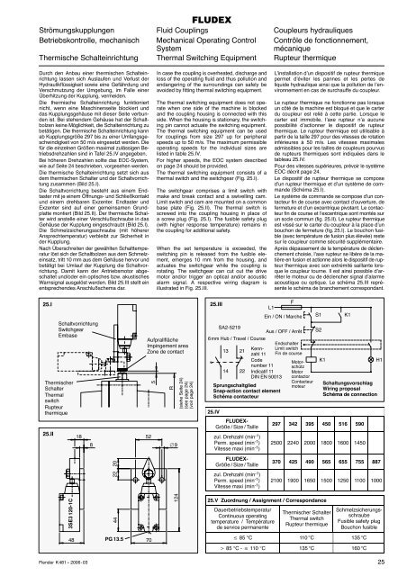
Die thermische Schalteinrichtung setzt sich aus<br />
dem thermischen Schalter und der Schaltvorrichtung<br />
zusammen (Bild 25.I).<br />
Die Schaltvorrichtung besteht aus einem Endtaster<br />
mit je einem Öffnungs- und Schließkontakt<br />
und einem drehbaren Exzenter. Endtaster und<br />
Exzenter sind auf einer gemeinsamen Grundplatte<br />
montiert (Bild 25.II). Der thermische Schalter<br />
wird anstelle einer Verschlußschraube in das<br />
Gehäuse der Kupplung eingeschraubt (Bild 25.I).<br />
Die Schmelzsicherungsschraube (mit höherer<br />
Ansprechtemperatur) verbleibt zur Sicherheit in<br />
der Kupplung.<br />
Nach Überschreiten der gewählten Schalttemperatur<br />
löst sich der Schaltbolzen aus dem Schmelzeinsatz,<br />
tritt 10 mm aus dem Gehäuse hervor und<br />
betätigt bei Umlauf der Kupplung die Schaltvorrichtung.<br />
Damit kann der Antriebsmotor abgeschaltet<br />
und/oder ein optisches bzw. akustisches<br />
Warnsignal ausgelöst werden. Bild 25.III stellt ein<br />
entsprechendes Anschlußschema dar.<br />
25.I<br />
25.II<br />
Schaltvorrichtung<br />
Switchgear<br />
Embase<br />
Thermischer<br />
Schalter<br />
Thermal<br />
switch<br />
Rupteur<br />
thermique<br />
3SE3 120-1C<br />
48<br />
18<br />
Flender K 481 � 2006 - 03<br />
8<br />
20<br />
22<br />
44<br />
PG 13.5<br />
In case the coupling is overheated, discharge and<br />
loss of the operating fluid and thus pollution and<br />
endangering of the surroundings can safely be<br />
avoided by fitting thermal switching equipment.<br />
The thermal switching equipment does not operate<br />
when one side of the machine is blocked<br />
and the coupling housing is connected with this<br />
side. When the housing is stationary, the switching<br />
pin cannot actuate the switching equipment.<br />
The thermal switching equipment can be used<br />
for couplings from size 297 up for peripheral<br />
speeds up to 50 m/s. The maximum permissible<br />
operating speeds for the individual sizes are<br />
listed in table 25.IV.<br />
For higher speeds, the EOC system described<br />
on page 24 should be provided.<br />
The thermal switching equipment consists of a<br />
thermal switch and the switchgear (Fig. 25.I).<br />
The switchgear comprises a limit switch with<br />
make and break contact and a swivelling cam.<br />
Limit switch and cam are mounted on a common<br />
base plate (Fig. 25.II). The thermal switch is<br />
screwed into the coupling housing in place of<br />
a screw plug (Fig. 25.I). The fusible safety plug<br />
(with higher response temperature) remains in<br />
the coupling for additional safety.<br />
When the set temperature is exceeded, the<br />
switching pin is released from the fusible element,<br />
emerges 10 mm from the housing, and<br />
actuates the switchgear while the coupling is<br />
rotating. The switchgear can cut out the drive<br />
motor and/or trigger an optical and/or acoustic<br />
alarm signal. A respective wiring diagram is<br />
illustrated in Fig. 25.III.<br />
Aufprallfläche<br />
Impingement area<br />
Zone de contact<br />
52<br />
70<br />
5<br />
R<br />
∅9<br />
124<br />
(siehe Seite 24)<br />
(see page 24)<br />
(voir page 24)<br />
25.III<br />
SA2-5219<br />
Aus / OFF / Arrêt<br />
6 mm Hub / Travel / Course<br />
25.IV<br />
13<br />
21<br />
14 22<br />
FLUDEX-<br />
Größe / Size / Taille<br />
zul. Drehzahl (min -1 )<br />
Perm. speed (min -1 )<br />
Vitesse maxi (min -1 )<br />
FLUDEX-<br />
Größe / Size / Taille<br />
zul. Drehzahl (min -1 )<br />
Perm. speed (min -1 )<br />
Vitesse maxi (min -1 )<br />
L’installation d’un dispositif de rupteur thermique<br />
permet d’éviter les pannes et les pertes de<br />
liquide hydraulique ainsi que la pollution de l’environnement<br />
en cas de surchauffe du coupleur.<br />
Le rupteur thermique ne fonctionne pas lorsque<br />
un côté de la machine est bloqué et que le carter<br />
du coupleur est relié à cette partie. Lorsque le<br />
carter est immobile, l’axe rupteur n’a aucune<br />
possibilité d’actionner le dispositif de rupteur<br />
thermique. Le rupteur thermique est utilisable à<br />
partir de la taille 297 pour des vitesses de rotation<br />
inférieures à 50 m/s. Les vitesses maximales<br />
admissibles pour les tailles de coupleurs pourvus<br />
de rupteurs thermiques sont indiquées dans le<br />
tableau 25.IV.<br />
Pour des vitesses supérieures, prévoir le système<br />
EOC décrit page 24.<br />
Le dispositif de rupteur thermique se compose<br />
d’un rupteur thermique et d’un système de commande<br />
(Schéma 25.I).<br />
Le système de commande se compose d’un contacteur<br />
fin de course avec contact d’ouverture, de<br />
fermeture et d’un excentrique pivotant. Le contacteur<br />
fin de course et l’excentrique sont montés sur<br />
un socle commun (fig. 25.II). Le rupteur thermique<br />
est vissé sur le carter du coupleur à la place d’un<br />
bouchon de fermeture (fig. 25.I). Le bouchon fusible<br />
(avec température de fusion plus élevée) reste<br />
sur le coupleur comme sécurité supplémentaire.<br />
Après dépassement de la température de déclenchement<br />
choisie, l’axe rupteur se libère de la matière<br />
en fusion et actionne alors le dispositif de rupteur<br />
thermique avec son extrémité saillante lorsque<br />
le coupleur tourne. Il est ainsi possible d’arrêter<br />
le moteur ou de déclencher signal d’alarme<br />
acoustique ou optique. Le schéma 25.III représente<br />
le schéma de branchement correspondant.<br />
297 342 395 450 516 590<br />
2500 2240 2000 1800 1600 1450<br />
370 425 490 565 655 755 887<br />
2100 1900 1650 1500 1250 1100 1000<br />
25.V Zuordnung / Assignment / Correspondance<br />
L1<br />
Kennzahl<br />
11<br />
Code<br />
number 11<br />
Indicatif 11<br />
DIN EN 50013<br />
Sprungschaltglied<br />
Snap-action contact element<br />
Schéma contacteur<br />
Dauerbetriebstemperatur<br />
Continuous operating<br />
temperature / Température<br />
de service permanente<br />
F<br />
Ein / ON / Marche<br />
Endschalter<br />
Limit switch<br />
Fin de course<br />
Motorschütz<br />
Motor<br />
contactor<br />
Contacteur<br />
moteur<br />
Thermischer Schalter<br />
Thermal switch<br />
Rupteur thermique<br />
Schaltungsvorschlag<br />
Wiring proposal<br />
Schéma de connection<br />
Schmelzsicherungsschraube<br />
Fusible safety plug<br />
Bouchon fusible<br />
� 85 °C 110 °C 135 °C<br />
� 85 °C - � 110 °C 135 °C 160 °C<br />
S1<br />
S2<br />
K1<br />
K1<br />
H1<br />
25


