
Create successful ePaper yourself
Turn your PDF publications into a flip-book with our unique Google optimized e-Paper software.
Strömungskupplungen<br />
������<br />
Fluid Couplings Coupleurs hydrauliques<br />
Betriebskontrolle, elektronisch Electronic Operating Contrôle de fonctionnement,<br />
EOC-System Control System électronique système EOC<br />
Mit dem “Electronic Operating Control”-System<br />
wird der Soll-Betriebszustand der FLUDEX-Kupplung<br />
berührungslos und wartungsfrei überwacht.<br />
Im Falle einer Überhitzung der Kupplung lassen<br />
sich Abspritzen und der Verlust der Betriebsflüssigkeit<br />
und die damit verbundene Verschmutzung<br />
und Gefährdung der Umgebung sowie eine längere<br />
Betriebsstörung vermeiden.<br />
Bei Antrieb über das Innenteil (Schaufelrad) kann<br />
zusätzlich zur Temperatur die Abtriebsdrehzahl<br />
(Mindestwert) überwacht werden.<br />
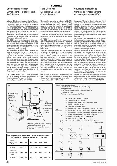
Das EOC-System besteht aus dem Geber, dem<br />
Aufnehmer und dem Auswertegerät. Der Geber<br />
wird anstelle einer Verschlußschraube in das<br />
Kupplungsgehäuse eingeschraubt (Bild 24.I), die<br />
Schmelzsicherungschraube (160 �C) verbleibt als<br />
Notsicherung in der Kupplung.<br />
Bei rotierender Kupplung und unterhalb der<br />
Ansprechtemperatur von 125 °C löst der Geber<br />
bei jeder Vorbeifahrt im Aufnehmer ein Impulssignal<br />
aus, das an das Auswertegerät weitergeleitet<br />
wird. Bleiben durch Überschreitung<br />
der Ansprechtemperatur die Impulse ganz<br />
aus (Temperaturüberwachungsfunktion), schaltet<br />
das Auswertegerät sofort und das Ausgangsrelais<br />
fällt ab. Mit Hilfe des Ausgangsrelais<br />
kann eine Störmeldung oder die Abschaltung<br />
des Antriebs ausgelöst werden (Schaltungsvorschlag<br />
24.III). Nach dem Abkühlen ist die<br />
Kupplung wieder betriebsbereit.<br />
Das Auswertegerät besitzt eine Anlaufüberbrückung,<br />
die eine Fehlermeldung während der<br />
Anlaufphase des Antriebes verhindert.<br />
Anschlußspannung: 20 ... 250 VAC/DC<br />
24.II Flugradius “R” zum Geber / Radius of travel “R” past<br />
the transmitter / Rayon de rotation “R” à l’indicateur<br />
FLUDEX-<br />
Größe / Size<br />
Taille<br />
297 342 395 450 516 590<br />
R (mm) 188 215 239 271 307 346<br />
FLUDEX-<br />
Größe / Size<br />
Taille<br />
370 425 490 565 655 755 887<br />
R (mm) 226 251 292 330 383 435 507<br />
The specified operating condition of a FLUDEX<br />
fluid coupling is monitored by a non-contacting,<br />
maintenance-free ”Electronic Operating Control”<br />
system. In case the coupling is overheated,<br />
discharge and loss of operating fluid and thus<br />
pollution and endangering of the surroundings<br />
as well as a longer downtime can be avoided.<br />
If driven via the impeller, the output speed (minimum<br />
value) can be monitored in addition to the<br />
temperature.<br />
The EOC system consists of a transmitter, a<br />
sensor and an evaluation instrument. The transmitter<br />
is screwed into the coupling housing in<br />
place of a screw plug (fig. 24.I). The fusible safety<br />
plug (160 �C) remains in the coupling for additional<br />
safety.<br />
When the coupling rotates and the response<br />
temperature is below 125 �C, the transmitter<br />
emits pulse signals to the sensor every time it<br />
passes. These signals are passed on to the<br />
evaluation instrument. If the pulses stop altogether<br />
because the response temperature is<br />
exceeded (temperature monitoring function),<br />
the evaluation instrument actuates immediately<br />
and the output relay is de-energized. The output<br />
relay can trigger a fault signal or switch off<br />
the drive (wiring proposal 24.III). The coupling<br />
is ready for operation again after having cooled<br />
down.<br />
One property of the evaluation instrument is delayed<br />
timing which inhibits an error message being<br />
tripped during the starting phase of the drive.<br />
Supply voltage: 20 ... 250 VAC/DC<br />
24.I 24.III<br />
Auswertegerät<br />
Evaluation<br />
instrument<br />
Système<br />
d’évaluation<br />
R<br />
2<br />
70<br />
M18 x 1<br />
FLUDEX<br />
SW 24<br />
Geber<br />
Transmitter<br />
Indicateur<br />
Aufnehmer<br />
Sensor<br />
Capteur<br />
Halterung (gehört nicht zur Lieferung)<br />
Bracket (not supplied by us)<br />
Support (ne fait pas partie de notre<br />
fourniture)<br />
Le système “Electronic Operating Control“ (EOC)<br />
sans contact et sans entretien permet de contrôler<br />
le fonctionnement du coupleur hydraulique<br />
FLUDEX en évitant les fuites et les pertes de<br />
liquide hydraulique, la pollution de l’environnement<br />
ainsi qu’une panne prolongée.<br />
Dans le cas d’entraînement par la partie interne<br />
(rotor de turbine) il est possible de contrôler, en<br />
plus de la température, la vitesse de sortie (valeur<br />
minimale).<br />
Le dispositif de surveillance est composé d’un<br />
indicateur de température, d’un capteur électromagnétique<br />
et du système d’évaluation. L’indicateur<br />
est monté sur le carter du coupleur à la<br />
place d’un bouchon de fermeture (schéma 24.I),<br />
le bouchon fusible (160 �C) reste sur le coupleur<br />
comme sécurité supplémentaire.<br />
Lorsque le coupleur tourne en dessous de la<br />
température de déclenchement de 125 °C, l’indicateur<br />
envoie à chaque passage un signal<br />
par impulsions au capteur. Ces signaux sont<br />
transmis au système d’évaluation. Les impulsions<br />
s’arrêtent lorsque la température est<br />
dépassé (fonction surveillance de la température),<br />
le système d’évaluation s’actualise immédiatement<br />
et le relais de sortie n’est plus alimenté.<br />
Le relais de sortie permet d’annoncer<br />
une panne ou bien de déclencher l’arrêt du<br />
système d’entraînement (Exemple de circuit<br />
24.III). Après refroidissement, le coupleur est<br />
de nouveau prêt à fonctionner.<br />
Le dispositif d’évaluation est muni d’un système<br />
de temporisation qui empêche le déclenchement<br />
de l’appareil pendant la phase de démarrage.<br />
Tension de raccordement: 20 ... 250 VAC/DC<br />
Schaltungsvorschlag:<br />
Motorabschaltung mit Meldeleuchte Störung<br />
Wiring proposal:<br />
Motor cut-out switch with trouble indicating lamp<br />
Exemple de circuit:<br />
Arrêt du moteur avec signal d’alerte<br />
B1 Aufnehmer / Sensor / Capteur<br />
F1 Sicherung / Fuse / Fusible<br />
F2 Motorschutzschalter / Motor protection switch<br />
Relais protection moteur<br />
H1 Störung / Fault / Anomalie<br />
K1 Motorschütz / Motor contactor / Contacteur de moteur<br />
K2 Hilfsschütz / Auxiliary contactor / Contacteur auxiliaire<br />
K3 Hilfsschütz / Auxiliary contactor / Contacteur auxiliaire<br />
S1 Not-Aus / Emergency OFF / Arrêt d’urgence<br />
S2 Motor Aus / Motor OFF / Arrêt moteur<br />
S3 Motor Ein / Motor ON / Marche moteur<br />
U1 Auswertegerät / Evaluation instrument / Système<br />
d’évaluation<br />
4 13 14<br />
2<br />
21 22<br />
31 32<br />
43 44<br />
24 Flender K 481 � 2006 - 03<br />
L1<br />
N<br />
-F1 1<br />
2<br />
-S1 11<br />
12<br />
-U1 5<br />
4 3<br />
-F2 1.21<br />
-K2 13<br />
-K1<br />
1.22<br />
2 14<br />
1<br />
3<br />
5<br />
A1<br />
A2<br />
2<br />
4<br />
6<br />
-S2 11<br />
-K2 23<br />
-S2 13<br />
21<br />
-K3 21<br />
-K2<br />
12<br />
14 22<br />
3 22<br />
A1<br />
A2<br />
3<br />
2 13 14<br />
3<br />
23 24<br />
3<br />
33 34<br />
5 43 44<br />
2 24<br />
-U1 5<br />
4 4<br />
-K2<br />
-S3 21<br />
-K3<br />
33<br />
2 34<br />
2 22<br />
A1<br />
A2<br />
-K3 13 -U1<br />
-H1<br />
3 14<br />
31<br />
32<br />
-B1<br />
-K2 43<br />
2 44<br />
1 13 14 15 16<br />
2 3 5 6 8<br />
3 4 5 7 8<br />
2 11 12 9- 10+<br />
-BU +BN<br />
NAMUR