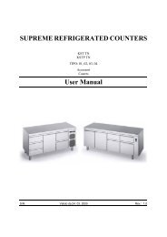
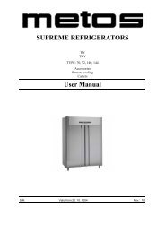
K/KU TN 70/72 K/KU TNV 70/140
K/KU TN 70/72 K/KU TNV 70/140
K/KU TN 70/72 K/KU TNV 70/140

Create successful ePaper yourself
Turn your PDF publications into a flip-book with our unique Google optimized e-Paper software.
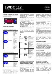
The appliance is fitted with a control panel found on the panel<br />
at the top of the door.<br />
The panel has been fitted with all the command and control<br />
devices required to operate the appliance:<br />
� - ON-OFF TELLTALE SWITCH<br />
�- FAN SWITCH ( NOT AVAILABLE ON MODELS WITH<br />
PLANT TYPE K<strong>TN</strong> 12 E K<strong>TN</strong> 13 ).<br />
�- LIGHT SWITCH (ONLY FOR GLASS DOOR)<br />
�- DEFROST LIGHT<br />
�- ELECTRONIC THERMOSTAT<br />
1.0 - TELLTALE SWITCH<br />
To turn the appliance on and off. The green light signals that<br />
voltage is supplied to the electric plant of the appliance.<br />
2.0 - FAN TELLTALE SWITCH<br />
To start or stop the fan inside the unit and to signal its<br />
operating status.<br />
By switching off the yellow switch the unit will operate by<br />
convection.<br />
3.0- LIGHT TELLTALE SWITCH<br />
Found only on the K <strong>TN</strong>V models (with glass door), coloured<br />
white.<br />
To turn ON and OFF the inside light and signal its status<br />
4.0- DEFROST LIGHT<br />
The red light referring to the unit defrost cycle.<br />
When ON, it signals that the unit is in the defrost phase.<br />
5.0 - ELECTRONIC THERMOSTAT<br />
To regulate the control and management of the operation of<br />
the appliance.<br />
5.1 - THERMOREGULATION<br />
The electronic thermostat acts to maintain the temperature<br />
inside the fridge compartment as close as possible to the Set<br />
Point value.<br />
Further to the Set Point the regulator uses another parameter<br />
- Hysterysis , that is factory set, and determines the range<br />
of fluctuation from the Set Point permitted for the fridge<br />
compartment temperature<br />
Example :<br />
with Set Point = -2°C and Hysterysis = 2°C we have :<br />
Pag. 18<br />
CONTROL PANEL<br />
CONTENTS:<br />
1.0 - ON-OFF TELLTALE SWITCH<br />
2.0 - FAN TELLTALE SWITCH<br />
3.0 - LIGHT TELLTALE SWITCH<br />
4.0 - DEFROST LIGHT<br />
5.0 - ELECTRONIC THERMOSTAT<br />
5.1 - THERMOREGULATION<br />
5.2 - COMPRESSOR TIMING<br />
5.3 - MAXIMUM AND MINIMUM TEMPERATURE ALARMS<br />
5.4 - EVAPORATOR FAN OPERATION MANAGEMENT<br />
5.5 - DEFROST MANAGEMENT<br />
6.0 - SET POINT<br />
6.1 - SET POINT VARIATION<br />
7.0 - OPERATING STATUS OF THE APPLIANCE COMPONENTS<br />
8.0 - ALARM CODE<br />
The compressor will start when the compartment temperature<br />
rises above :<br />
-2°C + ( 2°C ) = 0°C.<br />
The compressor stops when the compartment’s temperature<br />
reaches:<br />
-2 °C<br />
The Set Point is available to the user who can set the value,<br />
in degrees centigrade, as desired within a factory set range.<br />
This range is established to ensure the well being of the<br />
appliance and to ensure that the performance is respected.<br />
5.2 - COMPRESSOR TIMING<br />
The regulator, in controlling the compressor, accounts for<br />
certain timings. These timings have the function of:<br />
a) To limit the number of compressor starts per hour to a<br />
value established by its constructor.<br />
b) To ensure that, between one stop and the subsequent<br />
start-up of the compressor, there is a minimum delay to<br />
equalise the internal pressures.<br />
It is important to emphasise how the timing at point (a) counts<br />
the delay between one compressor start-up and the next.<br />
The values associated with each timing delay can only be<br />
set by parameters that are only accessible to the constructor<br />
or an authorised service centre.<br />
The compressor timing is signalled by the compressor LED<br />
flashing on the face of the thermostat, indicated by "comp"<br />
�.<br />
5.3 - MAXIMUM AND MINIMUM TEMPERATURE ALARMS<br />
The regulator supervises the management of both the maximum<br />
and minimum temperature alarms of the compartment.<br />
The values are set by parameters that are only<br />
accessible to the constructor or an authorised service centre<br />
and should be considered as the distance from the Set Point<br />
5.4 - EVAPORATOR FAN OPERATION MANAGEMENT<br />
( Function not available on models with plant type K <strong>TN</strong> 12<br />
e K <strong>TN</strong> 13 ).<br />
The regulator functions so that the fans inside the compartment<br />
only operate when specifically required. The parameters,<br />
only accessible to the constructor or the authorised<br />
service centres may be used to define<br />
- if the fans shutdown or not during defrost