4.1 Transfersystem TS 2plus Transfer system TS ... - Flex Industries bv
4.1 Transfersystem TS 2plus Transfer system TS ... - Flex Industries bv 4.1 Transfersystem TS 2plus Transfer system TS ... - Flex Industries bv
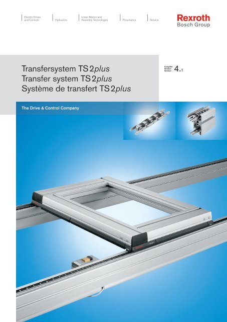
Electric Drives and Controls Hydraulics Linear Motion and Assembly Technologies Pneumatics Service Transfersystem TS 2plus Transfer system TS 2plus Système de transfert TS 2plus The Drive & Control Company Ausgabe Version Version 4.1
- Page 2 and 3: 0-2 Symbole Symbols Symbols 60 kg 1
- Page 4 and 5: 0-4 Bosch Rexroth AG TS 2plus 4.1 3
- Page 6 and 7: 1-2 Bosch Rexroth AG TS 2plus 4.1 E
- Page 8 and 9: 1-4 Bosch Rexroth AG TS 2plus 4.1 E
- Page 10 and 11: 1-6 Bosch Rexroth AG TS 2plus 4.1 E
- Page 12 and 13: 1-8 Bosch Rexroth AG TS 2plus 4.1 E
- Page 14 and 15: 1-10 Bosch Rexroth AG TS 2plus 4.1
- Page 16 and 17: 1-12 Bosch Rexroth AG TS 2plus 4.1
- Page 18 and 19: 1-14 Bosch Rexroth AG TS 2plus 4.1
- Page 20 and 21: 1-16 Bosch Rexroth AG TS 2plus 4.1
- Page 22 and 23: 1-18 Bosch Rexroth AG TS 2plus 4.1
- Page 24 and 25: 1-20 Bosch Rexroth AG TS 2plus 4.1
- Page 26 and 27: 1-22 Bosch Rexroth AG TS 2plus 4.1
- Page 28 and 29: 2-2 Bosch Rexroth AG TS 2plus 4.1 W
- Page 30 and 31: 2-4 Bosch Rexroth AG TS 2plus 4.1 W
- Page 32 and 33: 2-6 Bosch Rexroth AG TS 2plus 4.1 W
- Page 34 and 35: 2-8 Bosch Rexroth AG TS 2plus 4.1 W
- Page 36 and 37: 2-10 Bosch Rexroth AG TS 2plus 4.1
- Page 38 and 39: 2-12 Bosch Rexroth AG TS 2plus 4.1
- Page 40 and 41: 2-14 Bosch Rexroth AG TS 2plus 4.1
- Page 42 and 43: 2-16 Bosch Rexroth AG TS 2plus 4.1
- Page 44 and 45: 2-18 Bosch Rexroth AG TS 2plus 4.1
- Page 46 and 47: 2-20 Bosch Rexroth AG TS 2plus 4.1
- Page 48 and 49: 3-2 Bosch Rexroth AG TS 2plus 4.1 L
- Page 50 and 51: 3-4 Bosch Rexroth AG TS 2plus 4.1 L
Electric Drives<br />
and Controls<br />
Hydraulics<br />
Linear Motion and<br />
Assembly Technologies Pneumatics Service<br />
<strong><strong>Transfer</strong><strong>system</strong></strong> <strong>TS</strong> <strong>2plus</strong><br />
<strong>Transfer</strong> <strong>system</strong> <strong>TS</strong> <strong>2plus</strong><br />
Système de transfert <strong>TS</strong> <strong>2plus</strong><br />
The Drive & Control Company<br />
Ausgabe<br />
Version<br />
Version<br />
<strong>4.1</strong>
0–2<br />
Symbole<br />
Symbols<br />
Symbols<br />
60 kg<br />
1200mm<br />
240 mm<br />
100 N<br />
4...6 bar<br />
4 mm<br />
Clean<br />
Room<br />
Bosch Rexroth AG <strong>TS</strong> <strong>2plus</strong> <strong>4.1</strong><br />
Produkteigenschaften<br />
Product features<br />
Charactéristiques du produit<br />
Zulässige Belastung, Einzellast<br />
Permissible load, single load<br />
Charge maximale autorisée, charge unique<br />
Zulässige Belastung, Summenlast<br />
Permissible load, sum of loads<br />
Charge maximale autorisée, total des charges<br />
Reversierbetrieb bis 1200 mm zulässig<br />
Reverse operation permissible up to 1200 mm<br />
Fonctionnement inverse autorisée jusqu’à 1200 mm<br />
Hub über Transportniveau<br />
Lift above transpotation level<br />
Hauteur de levée sur niveau de transport<br />
Wiederholgenauigkeit<br />
Reproducing accuracy<br />
Précision de répétition<br />
Zulässige Prozesskraft<br />
Permissible process force<br />
Force de traitement maximale autorisée<br />
Einheit verfügt über eigenen Antrieb<br />
Unit has an own drive<br />
Module avec moteur traction<br />
Druckluftanschluß erforderlich<br />
Pneumatic connection required<br />
Raccordement pneumatique nécessaire<br />
Druckluft-Klemmanschluss "Steckfix"<br />
Pneumatic connection "Steckfix"<br />
kg/cm<br />
Raccordement pneumatique "Steckfix" Klassifikation LC (Light Class)<br />
Einsatztemperatur<br />
Operating temperature<br />
Température d‘utilisation<br />
Transportebene<br />
Transport level<br />
kg/cm<br />
Niveau de Transport Klassifikation HD (Heavy Duty)<br />
Geeignet für den Einsatz in Reinräumen<br />
Suitable for use in clean rooms<br />
Indiqué pour l’utilisation en zones propres<br />
Geeignet für Einsatz in elektrostatisch<br />
gefährdeten Bereichen. Die Rücksprache mit<br />
Ihrer Rexroth-Fachvertretung wird empfohlen.<br />
Suitable for use in ESD sensitive areas.<br />
A contact with your Rexroth representative is<br />
recommended.<br />
Indiqué pour l’utilisation en zones sensibles aux<br />
décharges électrostatiques. Nous conseillons<br />
contacter votre représentant Rexroth.<br />
Fördermittel<br />
Conveying media<br />
Convoyeurs<br />
Vplus<br />
Klassifikation<br />
Classification<br />
Classification<br />
kg/cm<br />
Verweise<br />
References<br />
Renvois<br />
Zahnriemen<br />
Toothed belt<br />
Courroie dentée<br />
Gurt<br />
Belt<br />
Courroie<br />
Flachplattenkette<br />
Flat top chain<br />
Chaîne à plate-formes<br />
Staurollenkette<br />
Accumulation roller chain<br />
Chaîne à rouleaux d’accumulation<br />
Rollen<br />
Rollers<br />
Rouleaux<br />
LC (Light Class) classification<br />
Classification LC (Light Class)<br />
Klassifikation MR (Mid Range)<br />
MR (Mid Range) classification<br />
Classification MR (Mid Range)<br />
HD (Heavy Duty) classification<br />
Classification HD (Heavy Duty)<br />
3 842 531 138 (2011.04)<br />
Staurollenkette Vplus<br />
Vplus Accumulation roller chain<br />
Chaîne à rouleaux d’accumulation Vplus<br />
Rundriemen<br />
Rounded belt<br />
Courroie ronde<br />
Verweis auf weiterführende Informationen<br />
Reference to additional information<br />
Renvoi à des informations supplémentaires<br />
Verweis auf technische Daten / Maße<br />
Reference to technical data/dimensions<br />
Renvoi à des données techniques/dimensions
3 842 531 138 (2011.04)<br />
<strong>TS</strong> <strong>2plus</strong> <strong>4.1</strong> Bosch Rexroth AG 0–3<br />
Systemübersicht <strong>TS</strong> <strong>2plus</strong><br />
System overview of <strong>TS</strong> <strong>2plus</strong><br />
Vue d’ensemble du système <strong>TS</strong> <strong>2plus</strong><br />
00108286.eps<br />
00108434.eps<br />
00108295.eps<br />
00013240.eps<br />
00013181.eps<br />
00013241.eps<br />
�� 2-5 �� 2-6 �� 2-8 �� 2-18<br />
00013208.eps<br />
�� 3-6 �� 3-12 �� 3-14 �� 3-16<br />
�� 3-26 �� 3-34 �� 3-38 �� 3-40<br />
�� 3-54 �� 3-60 �� 3-64 �� 3-66<br />
00125186.eps<br />
00012741.eps<br />
00012745.eps<br />
00012919.eps<br />
00012748.eps<br />
�� 4-4 �� 4-6 �� 4-16 �� 4-22<br />
00116138.eps<br />
00116135.eps<br />
�� 5-4 �� 5-14 �� 5-34 �� 5-38<br />
00116809.eps<br />
00116807.eps<br />
�� 6-4 �� 6-6 �� 6-7<br />
�� 7-4 �� 7-12 �� 7-16 �� 7-24<br />
00116596.eps<br />
00116592.eps<br />
00116805.eps<br />
00117846.eps 00116737.eps 00116755.eps<br />
�� 8-4 �� 8-19 �� 8-23 �� 8-31<br />
00117829.eps<br />
00116594.eps<br />
00012896.eps<br />
00012914.eps<br />
00116760.eps
0–4 Bosch Rexroth AG <strong>TS</strong> <strong>2plus</strong> <strong>4.1</strong> 3 842 531 138 (2011.04)
3 842 531 138 (2011.04)<br />
<strong>TS</strong> <strong>2plus</strong> <strong>4.1</strong> Bosch Rexroth AG 1–1<br />
Eigenschaften <strong>TS</strong> <strong>2plus</strong> · <strong>TS</strong> <strong>2plus</strong> features · Caractéristiques <strong>TS</strong> <strong>2plus</strong><br />
Inhaltsverzeichnis<br />
Table of Contents<br />
Sommaire<br />
Eigenschaften <strong>TS</strong> <strong>2plus</strong><br />
Werkstückträger<br />
Längstransport<br />
Kurven<br />
Quertransport<br />
Stützen<br />
Positionieren und Orientieren<br />
Transportsteuerung<br />
Identifikations<strong>system</strong>e<br />
Projektierung<br />
Technische Daten<br />
Bestellnummern-Übersicht<br />
Index<br />
Die angegebenen Daten dienen allein der Produktbeschreibung. Eine<br />
Aussage über eine bestimmte Beschaffenheit oder eine Eignung für einen<br />
bestimmten Einsatzzweck kann aus unseren Angaben nicht abgeleitet<br />
werden. Die Angaben entbinden den Verwender nicht von eigenen<br />
Beurteilungen und Prüfungen. Es ist zu beachten, dass unsere Produkte<br />
einem natürlichen Verschleiß- und Alterungsprozess unterliegen.<br />
<strong>TS</strong> <strong>2plus</strong> features<br />
Workpiece pallets<br />
Longitudinal conveyors<br />
Curves<br />
Transverse conveyors<br />
Leg sets<br />
Positioning and Orientation<br />
Transportation control<br />
Identification <strong>system</strong>s<br />
Planning<br />
Technical data<br />
Overview of part numbers<br />
Index<br />
The data specified above only serve to describe the product. No<br />
statements concerning a certain condition or suitability for a certain<br />
application can be derived from our information. The information given<br />
does not release the user from the obligation of own judgment and<br />
verification. It must be remembered that our products are subject to a<br />
natural process of wear and aging.<br />
Caractéristiques <strong>TS</strong> <strong>2plus</strong><br />
Palettes porte-pièces<br />
Transport longitudinal<br />
Courbes<br />
Transport transversal<br />
Supports<br />
Positionnement et Orientation<br />
Commande de transport<br />
Systèmes d’identification<br />
Projeter<br />
Données techniques<br />
Sommaire des références<br />
Index<br />
Les indications données servent exclusivement à la description du<br />
produit. Il ne peut être déduit de nos indications aucune déclaration<br />
quant aux propriétés précises ou à l’adéquation du produit en vue d’une<br />
application précise. Ces indications ne dispensent pas l’utilisateur d’une<br />
appréciation et d’une vérification personnelle. Il convient de tenir compte<br />
du fait que nos produits sont soumis à un processus naturel d’usure et<br />
de vieillissement.<br />
1<br />
2<br />
3<br />
4<br />
5<br />
6<br />
7<br />
8<br />
9<br />
10<br />
11<br />
12<br />
13<br />
14<br />
15<br />
16<br />
17
1–2<br />
Bosch Rexroth AG <strong>TS</strong> <strong>2plus</strong> <strong>4.1</strong><br />
Eigenschaften <strong>TS</strong> <strong>2plus</strong> · <strong>TS</strong> <strong>2plus</strong> features · Caractéristiques <strong>TS</strong> <strong>2plus</strong><br />
Funktionsprinzip<br />
Operating principle<br />
Principe de fonctionnement<br />
�<br />
In einer Montagelinie werden mit Hilfe<br />
eines <strong><strong>Transfer</strong><strong>system</strong></strong>s Werkstücke von<br />
Station zu Station befördert.<br />
Auf zwei stetig umlaufenden Gurten,<br />
Zahnriemen, Flachplattenketten oder<br />
Staurollenketten oder Rundriemen<br />
werden Werkstückträger (WT) über<br />
Reibung mitgenommen. Die WT<br />
nehmen die Werkstücke auf. Alle<br />
Bearbeitungen erfährt das Werk stück<br />
auf dem WT. Im Datenspeicher auf dem<br />
WT werden Infor mationen über Ziele<br />
und Bearbeitungszustände mitgeführt.<br />
An den Stationen (Handarbeitsplätzen<br />
oder Automatikstationen) wird der<br />
WT durch Verein ze ler VE angehalten,<br />
während das Fördermittel weiterläuft. Vor<br />
einzelnen Stationen können mehrere WT<br />
aufgestaut werden. Damit können kleine<br />
Puffer gebildet werden. Nach beendetem<br />
Arbeitsgang an der je weiligen Station<br />
wird der WT für den Transport zur<br />
nächs ten Ar beitsstation freigegeben.<br />
Das Öff nen des pneumatischen VE<br />
erfolgt dabei manuell oder durch eine<br />
Stationssteuerung.<br />
Am Ende des Montageablaufes wird das<br />
fertig montierte Werkstück aus dem WT<br />
entnommen.<br />
�<br />
On an assembly line workpieces have<br />
to be transported from one station to<br />
another using a transfer <strong>system</strong>.<br />
Workpiece pallets (WT) are conveyed<br />
by friction on two constantly moving<br />
belts, toothed belts, flat top chains,<br />
accumulation roller chains or rounded<br />
belts. The workpiece pallets hold<br />
the workpieces. A workpiece on the<br />
workpiece pallets is transported through<br />
all the processing stages. Information<br />
about destination and processing<br />
stage are carried in the workpiece<br />
pallet memory. The workpiece pallet is<br />
stopped by stop gates at stations (areas<br />
for manual work or automatic stations),<br />
while the conveyor continues moving.<br />
Several workpiece pallets can be built up<br />
in front of certain stations, to form small<br />
buffers. Once the processing stage at<br />
a station is completed, the workpiece<br />
pallet is released to travel on to the<br />
next work station. At the same time, the<br />
pneumatic stop gate is opened, either<br />
manually or with a station control.<br />
At the end of the assembly process<br />
the workpiece is removed from the<br />
workpiece pallet.<br />
Hauptschluss<br />
Main circuit<br />
Circuit principal<br />
3 842 531 138 (2011.04)<br />
�<br />
Dans une chaîne de montage les pièces<br />
sont transportées d’un poste à l’autre à<br />
l’aide d’un système de transfert.<br />
Des palettes porte-pièces (WT)<br />
sont convoyées par friction sur deux<br />
courroies de transport, courroies<br />
dentées, chaînes à plate-formes,<br />
chaînes à galets d‘accumulation ou<br />
corroies rondes continuellement en<br />
mouvement. Les palettes porte-pièces<br />
servent à la réception des pièces. La<br />
pièce est entièrement usinée sur la<br />
palette porte-pièces. Les informations<br />
concernant les destinations et l‘état<br />
d‘usinage sont enregistrées dans la<br />
mémoire de données sur la palette<br />
porte-pièces. La palette porte-pièces est<br />
stoppée aux postes de travail (postes de<br />
travail manuel et postes automatiques)<br />
grâce au séparateur VE pendant que<br />
le convoyeur continue à avancer.<br />
Plusieurs palettes porte-pièces peuvent<br />
être accumulées devant un poste<br />
permettant d‘en avoir quelques-unes<br />
d‘avance. Une fois l‘opération terminée<br />
au poste de travail correspondant, la<br />
palette porte-pièce peut passer au<br />
poste de travail suivant. L‘ouverture du<br />
séparateur pneumatique VE se fait alors<br />
soit manuellement, soit à l‘aide de la<br />
commande poste.<br />
En fin de chaîne de montage, la pièce<br />
assemblée est enlevée de la palette<br />
porte-pièce.
3 842 531 138 (2011.04)<br />
<strong>TS</strong> <strong>2plus</strong> <strong>4.1</strong> Bosch Rexroth AG 1–3<br />
Eigenschaften <strong>TS</strong> <strong>2plus</strong> · <strong>TS</strong> <strong>2plus</strong> features · Caractéristiques <strong>TS</strong> <strong>2plus</strong><br />
Layoutplanung<br />
Layout planning<br />
Conception du schéma d‘implantation<br />
�<br />
Bei der Planung eines Anlagen-Layouts<br />
spielt die Frage nach den individuellen<br />
Anforderungen, Zielen und Zielprioritäten<br />
des Unternehmens eine wichtige Rolle.<br />
Komplexe Montageabläufe erfordern<br />
häufig eine hohe Systemflexibilität<br />
aufgrund:<br />
– hoher Umrüsthäufigkeit<br />
– variantenabhängiger<br />
Abtaktungsprobleme<br />
– unterschiedlicher Arbeitsinhalte in den<br />
Stationen<br />
– häufiger Erzeugnisänderungen<br />
– starker Stückzahlschwankungen<br />
In solchen Fällen ist ein Ausschleusen<br />
der WT aus dem Hauptumlauf<br />
(Hauptschluss) in taktunabhängige<br />
Nebenschlussplätze sinnvoll.<br />
Als Hauptschluss bezeichnet man die<br />
Anordnung von Arbeitsplätzen/Stationen<br />
in Reihe.<br />
Nebenschluss ist das Ausschleu sen<br />
von WT aus dem Hauptschluss zur<br />
taktunabhängigen Bearbeitung mit<br />
anschließendem Wiedereinschleusen in<br />
den Hauptschluss.<br />
Nebenschluss<br />
Shunt<br />
Circuit dérivé<br />
�<br />
When planning the layout of a <strong>system</strong>,<br />
it is very important to enquire about the<br />
individual requirements, targets and<br />
priorities of a company. A very flexible<br />
<strong>system</strong> is often required for complex<br />
assembly procedures.<br />
This may be due to:<br />
– very frequent conversion<br />
– cycle problems due to different<br />
models<br />
– differences in the work involved at<br />
each station<br />
– frequent product alterations<br />
– great fluctuation in number of<br />
workpieces<br />
In cases like this, it is practical to<br />
transfer the workpiece pallet off the<br />
main conveyor (main circuit) into a shunt<br />
<strong>system</strong> which is independent of the main<br />
cycle.<br />
The term main circuit is used to describe<br />
workplaces or stations arranged in<br />
series.<br />
A shunt is when workpiece pallets<br />
are directed out of the main circuit for<br />
processing independently of the main<br />
cycle, and then reintegrated in the main<br />
circuit.<br />
Mischform<br />
Mixed System<br />
Forme mixte<br />
�<br />
Lors de la conception du schéma<br />
d'implantation d'une installation, les<br />
besoins individuels, les objectifs et les<br />
priorités d'une entreprise jouent un rôle<br />
primordial. La complexité de certains<br />
cycles de montage demande souvent<br />
une grande flexibilité de la part du<br />
système en raison de:<br />
– des transformations très fréquentes<br />
– des problèmes de concordance des<br />
cadences différentes suivant les<br />
variantes utilisées<br />
– des différentes opérations réalisées<br />
dans les postes de travail<br />
– des changements fréquents de produit<br />
– des variations importantes dans le<br />
nombre de pièces<br />
Dans ces cas là, il est utile de prévoir<br />
une sortie de la palette porte-pièces du<br />
circuit principaI dans un circuit dérivé<br />
ayant sa propre cadence.<br />
On désigne comme circuit principal<br />
l‘alignement les uns à côté des autres<br />
des postes de travail. Un circuit dérivé<br />
est conçu pour dégager les palettes<br />
porte-pièces du circuit principal, pour<br />
un usinage à une autre cadence et<br />
pour ensuite les remettre sur le circuit<br />
principal.<br />
1<br />
2<br />
3<br />
4<br />
5<br />
6<br />
7<br />
8<br />
9<br />
10<br />
11<br />
12<br />
13<br />
14<br />
15<br />
16<br />
17
1–4<br />
Bosch Rexroth AG <strong>TS</strong> <strong>2plus</strong> <strong>4.1</strong><br />
Eigenschaften <strong>TS</strong> <strong>2plus</strong> · <strong>TS</strong> <strong>2plus</strong> features · Caractéristiques <strong>TS</strong> <strong>2plus</strong><br />
Anlagenlayouts<br />
System layouts<br />
Schémas d‘implantation des installations<br />
Hauptschluss<br />
Main circuit<br />
Circuit principal<br />
Karreebauweise<br />
Rectangular circuit<br />
Circuit carrée<br />
3 842 531 138 (2011.04)<br />
Linienbauweise (mit Lift*)<br />
Linear construction (with lift*)<br />
Construction en ligne<br />
(avec élévateur*)<br />
U-Form (mit Lift*)<br />
U-shape (with lift*)<br />
Forme en U (avec élévateur*)<br />
*Über Lifte beraten Sie unsere Partner.<br />
*Our partners can advise you about lifts.<br />
*Nos partenaires vous conseilleront<br />
sur les élévateurs.<br />
U-Form<br />
U-shape<br />
Forme en U
3 842 531 138 (2011.04)<br />
<strong>TS</strong> <strong>2plus</strong> <strong>4.1</strong> Bosch Rexroth AG 1–5<br />
Eigenschaften <strong>TS</strong> <strong>2plus</strong> · <strong>TS</strong> <strong>2plus</strong> features · Caractéristiques <strong>TS</strong> <strong>2plus</strong><br />
Nebenschluss<br />
Shunt<br />
Circuit dérivé<br />
Mischformen<br />
Mixed <strong>system</strong>s<br />
Formes mixtes<br />
Parallelarbeitsplätze<br />
Parallel workplaces<br />
Postes de travail en parallèle<br />
Karreebauweise mit Parallel-<br />
arbeitsplätzen<br />
Rectangular circuits with<br />
parallel workplaces<br />
Circuits carrées avec postes<br />
de travail en parallèle<br />
1<br />
2<br />
3<br />
4<br />
5<br />
6<br />
7<br />
8<br />
9<br />
10<br />
11<br />
12<br />
13<br />
14<br />
15<br />
16<br />
17
1–6<br />
Bosch Rexroth AG <strong>TS</strong> <strong>2plus</strong> <strong>4.1</strong><br />
Eigenschaften <strong>TS</strong> <strong>2plus</strong> · <strong>TS</strong> <strong>2plus</strong> features · Caractéristiques <strong>TS</strong> <strong>2plus</strong><br />
Lösungsbeispiele<br />
Design ideas<br />
Suggestions<br />
Längstransport<br />
Longitudinal conveyors<br />
Transport longitudinal<br />
�<br />
Für kürzere Strecken<br />
BS 2<br />
�<br />
Für größere Strecken und Lasten<br />
AS 2/R<br />
�<br />
For short units<br />
SZ 2<br />
�<br />
For long units and heavy loads<br />
ST 2 UM 2/R<br />
SZ 2<br />
3 842 531 138 (2011.04)<br />
�<br />
Pour des sections moins importantes<br />
�<br />
Pour des sections et des charges<br />
plus importantes
3 842 531 138 (2011.04)<br />
<strong>TS</strong> <strong>2plus</strong> <strong>4.1</strong> Bosch Rexroth AG 1–7<br />
Eigenschaften <strong>TS</strong> <strong>2plus</strong> · <strong>TS</strong> <strong>2plus</strong> features · Caractéristiques <strong>TS</strong> <strong>2plus</strong><br />
WT-Umlauf<br />
WT circuit<br />
Circuit WT<br />
�<br />
Für parallele Umsetzung der<br />
Werkstückträger<br />
�<br />
Für Karreebauweise<br />
HQ 2<br />
BS 2<br />
HQ 2<br />
RS 2<br />
�<br />
For parallel transfer of the pallets<br />
�<br />
For rectangular circuits<br />
�<br />
Pour une transposition parallèle des<br />
palettes<br />
�<br />
Pour des circuits carrées<br />
1<br />
2<br />
3<br />
4<br />
5<br />
6<br />
7<br />
8<br />
9<br />
10<br />
11<br />
12<br />
13<br />
14<br />
15<br />
16<br />
17
1–8<br />
Bosch Rexroth AG <strong>TS</strong> <strong>2plus</strong> <strong>4.1</strong><br />
Eigenschaften <strong>TS</strong> <strong>2plus</strong> · <strong>TS</strong> <strong>2plus</strong> features · Caractéristiques <strong>TS</strong> <strong>2plus</strong><br />
Systeme<br />
Systems<br />
Systèmes<br />
�<br />
Kostengünstige Standardlösung<br />
AS 2<br />
ST 2<br />
BS 2<br />
HQ 2<br />
HQ 2<br />
�<br />
Hohe Umbauflexibilität<br />
(einfacher Austausch von Stationen)<br />
�<br />
Economical standard solution<br />
UM 2<br />
HQ 2<br />
�<br />
Very versatile design<br />
(simple to inter-change stations)<br />
HQ 2<br />
SE 3<br />
3 842 531 138 (2011.04)<br />
�<br />
Solution standard à un prix avantageux<br />
00013022.eps<br />
�<br />
Construction facilement transformable<br />
(en échangeant les postes de travail)<br />
00013021.eps
3 842 531 138 (2011.04)<br />
<strong>TS</strong> <strong>2plus</strong> <strong>4.1</strong> Bosch Rexroth AG 1–9<br />
Eigenschaften <strong>TS</strong> <strong>2plus</strong> · <strong>TS</strong> <strong>2plus</strong> features · Caractéristiques <strong>TS</strong> <strong>2plus</strong><br />
Systeme<br />
Systems<br />
Systèmes<br />
�<br />
– Einfache Erweiterung der Anlage mit<br />
zusätzlichen Stationen<br />
– Hohe Wiederverwendbarkeit ganzer<br />
Anlagenteile<br />
HQ 2<br />
HQ 2<br />
�<br />
– Simple extension of <strong>system</strong> with<br />
additional stations<br />
– High degree of reusability of whole<br />
sections of the <strong>system</strong><br />
BS 2<br />
BS 2<br />
�<br />
– Installation facile à agrandir en<br />
ajoutant des postes supplémentaires<br />
– Taux de réutilisation élévé de parties<br />
entières de l’installation<br />
00013023.eps<br />
1<br />
2<br />
3<br />
4<br />
5<br />
6<br />
7<br />
8<br />
9<br />
10<br />
11<br />
12<br />
13<br />
14<br />
15<br />
16<br />
17
1–10<br />
Bosch Rexroth AG <strong>TS</strong> <strong>2plus</strong> <strong>4.1</strong><br />
Eigenschaften <strong>TS</strong> <strong>2plus</strong> · <strong>TS</strong> <strong>2plus</strong> features · Caractéristiques <strong>TS</strong> <strong>2plus</strong><br />
<strong><strong>Transfer</strong><strong>system</strong></strong>e – Übersicht<br />
<strong>Transfer</strong> <strong>system</strong>s – overview<br />
Systèmes de transfert – vue d‘ensemble<br />
�<br />
Material- und<br />
Informationsflusstechnik MIT<br />
Die Bezeichnung <strong>TS</strong> steht für flexibles<br />
<strong><strong>Transfer</strong><strong>system</strong></strong>. Die Systeme<br />
– <strong>TS</strong> 1, <strong>TS</strong> <strong>2plus</strong> und <strong>TS</strong> 5 –<br />
unterscheiden sich in Abmessungen und<br />
zulässigen Traglasten.<br />
Die <strong><strong>Transfer</strong><strong>system</strong></strong>e bestehen aus<br />
standardisierten Baueinheiten,die<br />
beliebig zu einem System kombinierbar<br />
sind. Dies ermöglicht die Ausführung<br />
zahlreicher Varianten und führt<br />
zu maßgeschneiderten Anlagen,<br />
abgestimmt auf die jeweilige<br />
Montageaufgabe.<br />
�<br />
Material and information flow<br />
technology MIT<br />
The letters <strong>TS</strong> stand for a flexible transfer<br />
<strong>system</strong>. The <strong>system</strong>s available<br />
– <strong>TS</strong> 1, <strong>TS</strong> <strong>2plus</strong> and <strong>TS</strong> 5<br />
– differ in size and permissible load.<br />
The transfer <strong>system</strong>s consist of<br />
standardized components that are<br />
freely combinable to form a <strong>system</strong>. This<br />
permits the construction of numerous<br />
variants and provides made-to-measure<br />
<strong>system</strong>s, tailored to the particular<br />
assembly task.<br />
�<br />
Technique de gestion du flux de<br />
matériels et d`informations MIT<br />
La dénomination <strong>TS</strong> est une abréviation<br />
pour un système de transfert flexible.<br />
Les systèmes – <strong>TS</strong> 1, <strong>TS</strong> <strong>2plus</strong> et <strong>TS</strong> 5<br />
– se différencient par leurs dimensions<br />
et les charges admissibles. Les<br />
systèmes de transfert sont composés de<br />
composants standardisés, combinables<br />
à volonté. Cela permet la construction<br />
de nombreuses variantes et l’obtention<br />
d’installations sur mesure, adaptées aux<br />
besoins spécifiques de chaque montage.<br />
<strong>TS</strong> 1<br />
<strong>TS</strong> 5<br />
<strong>TS</strong> <strong>2plus</strong><br />
3 842 531 138 (2011.04)
3 842 531 138 (2011.04)<br />
<strong>TS</strong> <strong>2plus</strong> <strong>4.1</strong> Bosch Rexroth AG 1–11<br />
Eigenschaften <strong>TS</strong> <strong>2plus</strong> · <strong>TS</strong> <strong>2plus</strong> features · Caractéristiques <strong>TS</strong> <strong>2plus</strong><br />
�<br />
Identifikations- und Datenträger<strong>system</strong>e<br />
speichern alle produkt- und<br />
prozessbezogenen Daten direkt am<br />
Werkstückträger und ermöglichen deren<br />
dezentrale oder zentrale Verarbeitung.<br />
�<br />
Identification and data storage <strong>system</strong>s<br />
store all product and process-related<br />
data directly on the workpiece pallet and<br />
enable local or central data processing.<br />
�<br />
Les systèmes d’identification et de<br />
supports de données enregistrent<br />
l’ensemble des données relatives aux<br />
produits et aux processus directement<br />
sur la palette porte pièces et permettent<br />
un traitement centralisé ou décentralisé.<br />
ID 15 ID 40<br />
ID 200<br />
1<br />
2<br />
3<br />
4<br />
5<br />
6<br />
7<br />
8<br />
9<br />
10<br />
11<br />
12<br />
13<br />
14<br />
15<br />
16<br />
17
1–12<br />
Bosch Rexroth AG <strong>TS</strong> <strong>2plus</strong> <strong>4.1</strong><br />
Eigenschaften <strong>TS</strong> <strong>2plus</strong> · <strong>TS</strong> <strong>2plus</strong> features · Caractéristiques <strong>TS</strong> <strong>2plus</strong><br />
Auswahldaten<br />
Selection data<br />
Données de sélection<br />
�<br />
Verfügbare Werkstückträger (WT) -<br />
Abmessungen<br />
Werkstückträger mit einer Grundfläche<br />
von 80 x 80 mm (<strong>TS</strong> 1) bis<br />
1243 x 1243 mm (<strong>TS</strong> <strong>2plus</strong>) erlauben<br />
die bedarfsgerechte Anpassung an die<br />
entsprechende WerkstückGeometrie.<br />
Bei Bedarf können auch mehrere<br />
Werkstücke auf einem Werkstückträger<br />
(WT) fixiert werden.<br />
Zulässige Werkstückträger (WT)<br />
-Auflagegewichtskraft F WT<br />
Um die zulässige Flächen pres sung<br />
zwischen WT und Fördermittel nicht zu<br />
überschreiten, ist für jede WTGröße<br />
die WTAuflagegewichtskraft F WT<br />
beschränkt.<br />
Die WTAuflagegewichtskraft F WT<br />
resultiert aus:<br />
– WTLeergewicht<br />
– WTZuladung (Werkstück, Aufnahme<br />
etc.)<br />
– Gewicht der Sonderausstattung<br />
(Datenspeicher, etc.)<br />
Bei nicht quadratischen Werkstückträgern<br />
ist zu beachten, dass die zulässige WT<br />
Auflagegewichtskraft F WT im Längs und<br />
Quertransport unterschiedlich sein kann.<br />
300 kg<br />
<strong>TS</strong> 5<br />
�<br />
Available workpiece pallet (WT)<br />
dimensions<br />
Workpiece pallets with a surface<br />
from 80 x 80 mm (<strong>TS</strong> 1) up to<br />
1243 x 1243 mm (<strong>TS</strong> <strong>2plus</strong>) allow for<br />
the correct choice of workpiece pallet<br />
for the particular workpiece geometry.<br />
If necessary, a number of work pieces<br />
can be accommodated on a single<br />
workpiece pallet (WT).<br />
Permissible loading weight for<br />
workpiece pallet F WT<br />
The workpiece pallet loading weight F WT<br />
of each workpiece pallet size is limited<br />
so that the permissible surface pressure<br />
between the workpiece pallet and<br />
conveying media is not exceeded.<br />
The workpiece pallet loading weight F WT<br />
consists of the following:<br />
– the empty weight of the workpiece<br />
pallet<br />
– the weight supported by the workpiece<br />
pallet (workpiece, holder, etc.)<br />
– the weight of special equipment (data<br />
storage, etc.)<br />
For workpiece pallets that are not<br />
square, please note that the permissible<br />
WT loading weight F WT may be different<br />
for longitudinal conveyors and transverse<br />
conveyors.<br />
250 kg<br />
<strong>TS</strong> 4plus<br />
k<br />
240 g<br />
<strong>TS</strong> <strong>2plus</strong><br />
3 842 531 138 (2011.04)<br />
�<br />
Dimensions de palettes porte-pièces<br />
(WT) disponibles<br />
Des palettes portepièces dont<br />
les dimensions sont comprises<br />
de 80 x 80 mm (<strong>TS</strong> 1) jusqu’à<br />
1243 x 1243 mm (<strong>TS</strong> <strong>2plus</strong>) permettent<br />
l’adaptation parfaite à la géométrie<br />
spécifique de la pièce. Une seule palette<br />
portepièces (WT) peut également<br />
recevoir plusieurs pièces, en fonction<br />
des besoins.<br />
Force massique admissible de palette<br />
porte-pièces F WT<br />
Pour ne pas dépasser la force<br />
superficielle admissible entre la palette<br />
portepièces et le convoyeur, la force<br />
massique F WT de la palette portepièces<br />
est limitée pour chaque taille de palette<br />
portepièces.<br />
La force massique F WT de palette<br />
portepièces résulte :<br />
– du poids propre de la palette<br />
portepièces<br />
– de la charge de la palette portepièces<br />
(pièce à usiner, support, etc.)<br />
– du poids des équipements spécifiques<br />
(support mobile de données, etc.)<br />
Pour des palettes portepièces non<br />
carrées, noter que la force massique<br />
autorisée de palette portepièces<br />
F WT peut différer en cas de transport<br />
longitudinal et transversal.<br />
3<br />
kg<br />
<strong>TS</strong> 1
3 842 531 138 (2011.04)<br />
<strong>TS</strong> <strong>2plus</strong> <strong>4.1</strong> Bosch Rexroth AG 1–13<br />
Eigenschaften <strong>TS</strong> <strong>2plus</strong> · <strong>TS</strong> <strong>2plus</strong> features · Caractéristiques <strong>TS</strong> <strong>2plus</strong><br />
Systemkenngrößen<br />
System parameters<br />
Grandeurs caractéristiques du système<br />
�<br />
Zulässige Streckenbelastung F G zul.<br />
Bei der Auslegung der Förderstrecken<br />
ist darauf zu achten, dass die<br />
Summe F G aller Werkstückträger-<br />
Auflagegewichtskräfte F WT , die sich<br />
gleichzeitig auf der Förderstrecke<br />
im Stau befinden, kleiner ist als die<br />
zulässige Streckenbelastung der<br />
Förderstrecke F G zul.<br />
Wird die zulässige Streckenbelastung<br />
F G zul. der Förderstrecke dabei überschritten,<br />
muss diese in mehrere<br />
Einzelstrecken unterteilt werden.<br />
Die zulässige Streckenbelastung<br />
der einzelnen Förderstrecken ist den<br />
Einzelbeschreibungen zu entnehmen.<br />
F =<br />
WT<br />
^<br />
�<br />
Permissible section loading F G zul.<br />
When designing the conveyor sections,<br />
it is important to ensure that the total<br />
mass F G of the loading weight of all<br />
workpiece pallets F WT which are on<br />
the conveyor section in accumulation<br />
operation at one time is below the<br />
permissible load for conveyor<br />
sections F G zul.<br />
If this permissible load F G zul. for the<br />
conveyor section is exceeded, the<br />
section must be divided into several<br />
individual sections. The permissible<br />
section loading of the individual<br />
conveyor sections can be determined<br />
from the individual descriptions.<br />
�<br />
Charge de section admissible F G zul.<br />
Lors de la conception des sections de<br />
transport, veillez à ce que le total F G<br />
des forces massiques de toutes les<br />
palettes porte-pièces F WT se trouvant<br />
sur un même convoyeur en accumulation<br />
soit inférieur à la charge maximale<br />
admissible des convoyeurs F G zul.<br />
Si ce total dépasse la charge maximale<br />
autorisée du convoyeur F G zul. il doit<br />
être réparti sur plusieurs sections.<br />
Vous trouverez la charge de section<br />
admissible dans la description détaillée<br />
de chaque convoyeur.<br />
1<br />
2<br />
3<br />
4<br />
5<br />
6<br />
7<br />
8<br />
9<br />
10<br />
11<br />
12<br />
13<br />
14<br />
15<br />
16<br />
17
1–14<br />
Bosch Rexroth AG <strong>TS</strong> <strong>2plus</strong> <strong>4.1</strong><br />
Eigenschaften <strong>TS</strong> <strong>2plus</strong> · <strong>TS</strong> <strong>2plus</strong> features · Caractéristiques <strong>TS</strong> <strong>2plus</strong><br />
Systemkenngrößen<br />
System parameters<br />
Grandeurs caractéristiques du système<br />
�<br />
Längstransport, Quertransport<br />
Das Transportniveau des Quertransports<br />
liegt über dem des Längs transports. Die<br />
Haupttransportrichtung einer Anlage ist<br />
der Längstransport.<br />
�<br />
Spurbreite<br />
Die Spurbreite b ergibt sich<br />
direkt aus den entsprechenden<br />
Werkstückträger-Abmes sun gen<br />
b WT und l WT. Daher ist zu beachten,<br />
dass bei rechteckigen (also nicht<br />
quadratischen) Werkstückträgern die<br />
Spurbreiten b für Längstransport und<br />
Quertransport unterschiedlich sind.<br />
�<br />
Longitudinal conveyor, transverse<br />
conveyor<br />
The transport level of transverse conveyor<br />
is above that of the longitudinal<br />
conveyor. A <strong>system</strong>‘s main direction<br />
of transportation is the longitudinal<br />
conveyor.<br />
�<br />
Track width<br />
The track width b is directly related<br />
to the workpiece pallet dimensions<br />
b WT and l WT. For this reason, the<br />
conveyor track widths b are different<br />
for the longitudinal and transverse<br />
conveyors if the workpiece pallet is<br />
rectangular, i.e. not square.<br />
b Q<br />
b L<br />
3 842 531 138 (2011.04)<br />
�<br />
Transport longitudinal, transport<br />
transversal<br />
Le niveau de transport transversal<br />
est supérieur à celui du transport<br />
longitudinal. Le sens principal de<br />
transport d‘une installation est celui<br />
longitudinal.<br />
�<br />
Ecartement de la voie<br />
L‘écartement de la voie b est<br />
calculé à partir des dimensions<br />
correspon dantes de la palette<br />
porte-pièces b WT et l WT. C‘est<br />
pourquoi, les écartements de la voie<br />
b de la section pour les transports<br />
longitudinales et transversales sont<br />
différent si la palette porte-pièces<br />
est rectangulaire (c’est à dire pas<br />
carrée).
3 842 531 138 (2011.04)<br />
<strong>TS</strong> <strong>2plus</strong> <strong>4.1</strong> Bosch Rexroth AG 1–15<br />
Eigenschaften <strong>TS</strong> <strong>2plus</strong> · <strong>TS</strong> <strong>2plus</strong> features · Caractéristiques <strong>TS</strong> <strong>2plus</strong><br />
�<br />
Zulässige Schwerpunktlage<br />
Um die Beschleunigungskräfte bei<br />
Vereinzelung oder Richtungsänderungen<br />
(Kurven, Wechsel in die<br />
Quertransportrichtung) störungsfrei<br />
aufnehmen zu können, ist die Lage des<br />
Beladungsschwerpunktes auf dem<br />
Werkstückträger zu beachten.<br />
Generell empfehlen wir:<br />
1. die Werkstückträger möglichst mittig<br />
zu belasten<br />
2. den Beladungsschwerpunkt<br />
in der Höhe hS nicht über<br />
1/2 bWT (mit bWT ≤ lWT) hinauskommen zu lassen<br />
�<br />
Permissible gravity center position<br />
When separating pallets or changing<br />
directions (curves, change in the<br />
transverse conveyor direction), it is<br />
important to observe the position of the<br />
gravity center load on the workpiece<br />
pallet to ensure that the acceleration<br />
forces can be absorbed without any<br />
interferences.<br />
Generally we recommend that:<br />
1. The load should be positioned in the<br />
center of the workpiece pallet<br />
2. The center of gravity should<br />
not exceed a height h S of<br />
1/2 b WT (with b WT ≤ l WT)<br />
�<br />
Position admissible du centre de<br />
gravité<br />
Afin de pouvoir supporter les forces<br />
accélératrices lors de séparation ou<br />
modifications de direction (courbes,<br />
changement dans la direction de transport<br />
transversal) sans défaut, il faut faire<br />
attention à la position du centre de gravité<br />
de la charge sur la palette porte-pièces.<br />
En generale nous conseillons :<br />
1. de charger la palette porte-pièces le<br />
plus au centre possible<br />
2. de ne pas laisser le centre de gravité<br />
de la charge dépasser dans la hauteur<br />
h S 1/2 b WT (avec b WT ≤ l WT)<br />
1<br />
2<br />
3<br />
4<br />
5<br />
6<br />
7<br />
8<br />
9<br />
10<br />
11<br />
12<br />
13<br />
14<br />
15<br />
16<br />
17
1–16<br />
Bosch Rexroth AG <strong>TS</strong> <strong>2plus</strong> <strong>4.1</strong><br />
Eigenschaften <strong>TS</strong> <strong>2plus</strong> · <strong>TS</strong> <strong>2plus</strong> features · Caractéristiques <strong>TS</strong> <strong>2plus</strong><br />
Systemkenngrößen<br />
System parameters<br />
Grandeurs caractéristiques du système<br />
�<br />
Verwendete Materialien,<br />
Medienbeständigkeit<br />
Die Rexroth-<strong><strong>Transfer</strong><strong>system</strong></strong>e werden<br />
für den Dauereinsatz aus hochwertigen<br />
Materialien hergestellt. Sie sind<br />
beständig gegen die in normaler<br />
Industrieumgebung üblicherweise<br />
vorkommenden Schmier- und<br />
Pflegemittel. Im Rahmen dieses<br />
Kataloges kann jedoch keine Gewähr<br />
für die Beständigkeit gegenüber allen<br />
möglichen Kombinationen an Prüffluiden,<br />
Gasen oder Lösemitteln übernommen<br />
werden. Bitte erkundigen Sie sich<br />
hierzu im Zweifelsfall bei Ihrer Rexroth-<br />
Fachvertretung.<br />
Verwendbarkeit in elektrostatisch<br />
gefährdeten Bereichen<br />
Nahezu alle Komponenten und Bauteile<br />
der Rexroth-<strong><strong>Transfer</strong><strong>system</strong></strong>e sind<br />
leitfähig beziehungsweise in leitfähiger<br />
Ausführung erhältlich. Sie sind damit<br />
grundsätzlich für den Einsatz in EPA<br />
(ESD Protected Areas – elektrostatisch<br />
gefährdeten Bereichen) geeignet.<br />
Im Einzelfall empfehlen wir hierzu<br />
die Rücksprache mit Ihrer Rexroth-<br />
Fachvertretung.<br />
�<br />
Materials used, resistance to media<br />
Rexroth transfer <strong>system</strong>s are<br />
manufactured with high-quality materials<br />
to ensure continuous use. They are<br />
resistant to lubricating and cleansing<br />
agents that are common in an industrial<br />
environment. However, we cannot<br />
guarantee that the products contained<br />
in this catalog are resistant to all<br />
combinations of testing liquids, gases,<br />
or solvents. Please contact your Rexroth<br />
representative if you have any doubts.<br />
Suitability for electrostatically<br />
sensitive areas<br />
Almost all of the components and<br />
parts in Rexroth transfer <strong>system</strong>s<br />
are ESD-compatible or available in<br />
ESD-compatible design. They can<br />
thus principally be used in EPA (ESD<br />
protected areas). We do, however,<br />
recommend that you contact your<br />
Rexroth representative.<br />
3 842 531 138 (2011.04)<br />
�<br />
Matériaux utilisés, résistance<br />
chimique<br />
Les systèmes de transfert Rexroth<br />
sont fabriqués pour l‘utilisation de<br />
longue durée à partir de matériaux de<br />
haute qualité. Ils sont résistants aux<br />
matières lubrifiantes et aux produits<br />
d‘entretien rencontrés d‘habitude dans<br />
un environnement industriel normal.<br />
Dans le cadre de ce catalogue, aucune<br />
garantie ne peut toutefois être donnée<br />
pour la résistance vis-à-vis de toutes<br />
les combinaisons possibles de fluides<br />
d‘essai, gaz ou solvants. Dans le doute,<br />
veuillez vous renseigner sur ce point<br />
auprès de votre représentant spécialisé<br />
Rexroth.<br />
Utilité pratique dans les zones<br />
sensibles aux décharges<br />
électrostatiques<br />
Presque tous les composants et<br />
éléments de construction des systèmes<br />
de transfert Rexroth possèdent une<br />
capacité de décharge électrostatique<br />
ou sont disponibles en version avec<br />
capacité de décharge électrostatique.<br />
Ils sont ainsi essentiellement<br />
appropriés pour l‘utilisation en EPA<br />
(zones protegées contre décharges<br />
électrostatiques). Au cas par cas, nous<br />
conseillons sur ce point un entretien<br />
préliminaire avec votre représentant<br />
spécialisé Rexroth.
3 842 531 138 (2011.04)<br />
<strong>TS</strong> <strong>2plus</strong> <strong>4.1</strong> Bosch Rexroth AG 1–17<br />
Eigenschaften <strong>TS</strong> <strong>2plus</strong> · <strong>TS</strong> <strong>2plus</strong> features · Caractéristiques <strong>TS</strong> <strong>2plus</strong><br />
Eigenschaften <strong>TS</strong> <strong>2plus</strong><br />
<strong>TS</strong> <strong>2plus</strong> Features<br />
Caractéristiques du <strong>TS</strong> <strong>2plus</strong><br />
�<br />
Das Rexroth <strong><strong>Transfer</strong><strong>system</strong></strong> <strong>TS</strong> <strong>2plus</strong><br />
ist das Multitalent für die wirtschaftliche<br />
Fertigung. Es bildet einen vielseitigen<br />
Systembaukasten, der zu einem breiten<br />
Spektrum an Produkten passt.<br />
Vielseitig, robust, variabel<br />
Durch die Vielzahl der Baukastenelemente<br />
ist die Anpassung an spezielle<br />
Fertigungsaufgaben und individuelle<br />
Layoutwünsche ohne weiteres möglich:<br />
– Vier kombinierbare Fördermittel<br />
(Polyamidgurt, Zahnriemen,<br />
Flachplattenkette und Staurollenkette)<br />
entsprechend den Erfordernissen des<br />
Montageprozesses.<br />
– Auf die Produktgröße abgestimmte<br />
Werkstückträgergrößen<br />
(160 x 160 mm bis 1040 x 800 mm)<br />
– Hohe Maximalbelastung von bis zu<br />
70 kg pro Werkstückträger.<br />
Spezielle <strong>TS</strong> <strong>2plus</strong> Baueinheiten<br />
Neben den verschiedenen Fördermitteln<br />
bietet <strong>TS</strong> <strong>2plus</strong> eine Fülle spezifischer<br />
Baueinheiten im Bereich Kurven, Quertransport,<br />
Positionier- und Antriebseinheiten.<br />
Außerdem lassen sich<br />
Planungs- und Projektierungsaufwand<br />
mit dem Angebot an vordefinierten<br />
Makromodulen auf ein Minimum<br />
reduzieren.<br />
Die über den Katalog bestellbaren<br />
Material-Kombinationen sind für den<br />
regulären Betrieb des <strong>TS</strong> <strong>2plus</strong> optimiert.<br />
Für besondere Anwendungen sind weitere<br />
Materialkombinationen möglich. Bei<br />
Bedarf empfehlen wir eine Rücksprache<br />
mit Ihrer Rexroth-Fachvertretung.<br />
�<br />
The Rexroth <strong>TS</strong> <strong>2plus</strong> transfer <strong>system</strong> is a<br />
multi-talented <strong>system</strong>, which guarantees<br />
economic production. It is a diverse modular<br />
<strong>system</strong> that meets the requirements<br />
of a wide range of different products.<br />
Diverse, sturdy, adaptable<br />
Due to the large number of modular<br />
components incorporated in the<br />
<strong>system</strong>, it can be adapted to suit<br />
specific production conditions and<br />
individual layouts without requiring<br />
any extra parts:<br />
– Four types of conveying media<br />
(polyamide belts, toothed belts, flat<br />
top chains and accumulation roller<br />
chains) which can be combined<br />
together to meet the needs of the<br />
assembly process.<br />
– Workpiece pallets sizes (from<br />
160 x 160 mm up to 1040 x 800 mm)<br />
specifically designed for the product sizes.<br />
– A high maximum load of up to 70 kg per<br />
workpiece pallet.<br />
Special <strong>TS</strong> <strong>2plus</strong> units<br />
Apart from the different types of<br />
conveying media, the <strong>TS</strong> <strong>2plus</strong> also<br />
provides an abundance of specific units<br />
including curves, transverse conveyors,<br />
positioning and drive units. In addition to<br />
this, the time and effort spent on planning<br />
and designing can also be reduced<br />
to a minimum thanks to the range of<br />
predefined macro modules.<br />
Material combinations that can be ordered<br />
from the catalog have been optimized for<br />
standard operation with <strong>TS</strong> <strong>2plus</strong>. For<br />
special applications, additional material<br />
combinations are available. Please<br />
contact your Rexroth sales office if you<br />
require a special combination.<br />
�<br />
Le système de transfert <strong>TS</strong> <strong>2plus</strong> de<br />
Rexroth possède plusieurs facettes et de<br />
ce fait permet de produire de manière rentable.<br />
C’est un système modulaire doté de<br />
nombreuses facettes, adapté à une large<br />
gamme de produits.<br />
A usages multiples, robuste, variable<br />
Les nombreux éléments du système<br />
modulaire permettent une adaptation à des<br />
tâches de production et des schémas d’implantation<br />
spécifiques, sans problèmes,<br />
grâce à :<br />
– Quatre modes de transport (des<br />
courroies en polyamide, des courroies<br />
crantées, des chaînes à plates-formes et<br />
des chaînes à rouleaux d’accumulation)<br />
pouvant être combinés en fonction des<br />
impératifs du processus de montage<br />
– Des tailles des palettes porte-pièces<br />
(de 160 x 160 mm jusqu’a<br />
1040 x 800 mm) adaptées à la taille du<br />
produit<br />
– Une capacité de charge maximale élevée<br />
pouvant atteindre 70 kg par palette<br />
porte-pièces.<br />
Modules <strong>TS</strong> <strong>2plus</strong> spéciaux<br />
Mis à part les différents modes de transport,<br />
le <strong>TS</strong> <strong>2plus</strong> offre toute une série de<br />
modules spécifiques relatifs aux courbes,<br />
au transport transversal, aux unités de positionnement<br />
et d’entraînement. En outre, les<br />
coûts de planification et de projet peuvent<br />
être réduits à un minimum grâce à l’utilisation<br />
de macro-modules prédéfinis.<br />
Les combinaison de matériaux pouvant<br />
être commandés avec le catalogue sont<br />
optimisées pour l’exploitation régulière du<br />
<strong>TS</strong> <strong>2plus</strong>. Toutefois, d’autres combinaisons<br />
de matériaux sont possibles pour des applications<br />
particulières. En cas de besoin,<br />
nous vous conseillons de contacter votre<br />
représentant Rexroth.<br />
1<br />
2<br />
3<br />
4<br />
5<br />
6<br />
7<br />
8<br />
9<br />
10<br />
11<br />
12<br />
13<br />
14<br />
15<br />
16<br />
17
1–18<br />
Bosch Rexroth AG <strong>TS</strong> <strong>2plus</strong> <strong>4.1</strong><br />
Eigenschaften <strong>TS</strong> <strong>2plus</strong> · <strong>TS</strong> <strong>2plus</strong> features · Caractéristiques <strong>TS</strong> <strong>2plus</strong><br />
Eigenschaften <strong>TS</strong> <strong>2plus</strong><br />
<strong>TS</strong> <strong>2plus</strong> Features<br />
Caractéristiques du <strong>TS</strong> <strong>2plus</strong><br />
�<br />
Applikationsbeispiele<br />
Mit der großen Bandbreite unterschiedlichster<br />
Einsatzmöglichkeiten lässt sich<br />
die Vielfalt des <strong>TS</strong> <strong>2plus</strong> am besten<br />
beschreiben, z.B. in den Bereichen<br />
Kfz-Zulieferer (Getriebe, Autoradios,<br />
Scheinwerfer, Schiebedächer),<br />
Elektronik (Computer, Monitore, Drucker,<br />
Decoder) bis hin zu Haushaltsgeräten<br />
(Kaffeemaschinen, Waschmaschinen)<br />
und Elektrowerkzeugen (Bohrschrauber,<br />
Schleifgeräte).<br />
l = 160 - 1040 mm F<br />
WT WT max<br />
bb =<br />
160-800 mm<br />
WT<br />
�<br />
Application examples<br />
The wide range of different applications<br />
demonstrates just how diverse<br />
the <strong>TS</strong> <strong>2plus</strong> is: it is used for example<br />
in the fields of automotive suppliers<br />
(gears, car radios, headlights, sunroofs),<br />
electronics (computers, monitors,<br />
printers, decoders) as well as for<br />
producing household appliances (coffee<br />
machines, washing machines) and<br />
electric tools (drills, cutters).<br />
v =<br />
12 m/min<br />
N<br />
3 842 531 138 (2011.04)<br />
00116126.eps<br />
�<br />
Exemples d’utilisation<br />
Les différents aspects du système<br />
<strong>TS</strong> <strong>2plus</strong> permettent un grand nombre<br />
d’applications dont les exemples les<br />
plus significatifs sont la sous-traitance<br />
de l’industrie automobile (boîtes de<br />
vitesses, autoradios, phares, toits<br />
ouvrants), l’électronique (ordinateurs,<br />
écrans, imprimantes, décodeurs) et<br />
également l’électroménager (cafetières<br />
électriques, lavelinges) et les outils<br />
électriques (perceuses-visseuses,<br />
ponceuses).
3 842 531 138 (2011.04)<br />
<strong>TS</strong> <strong>2plus</strong> <strong>4.1</strong> Bosch Rexroth AG 1–19<br />
Eigenschaften <strong>TS</strong> <strong>2plus</strong> · <strong>TS</strong> <strong>2plus</strong> features · Caractéristiques <strong>TS</strong> <strong>2plus</strong><br />
Anwendungsklassen<br />
Application classes<br />
Classes d‘application<br />
kg/cm kg/cm kg/cm<br />
�<br />
Mit seinem umfangreichen Baukasten<br />
kann das <strong><strong>Transfer</strong><strong>system</strong></strong> <strong>TS</strong> <strong>2plus</strong><br />
für eine Vielzahl von Anwendungen<br />
maßgeschneidert werden. Abhängig von<br />
Werkstückgröße und -gewicht, sowie<br />
den sonstigen Einsatzbedingungen<br />
lassen sich dabei folgende<br />
Anwendungsklassen unterscheiden:<br />
Klassifikation:<br />
Classification:<br />
Classification :<br />
kg/cm<br />
Klassifikation<br />
Classification<br />
Classification<br />
�<br />
With its extensive construction kit<br />
the transfer <strong>system</strong> <strong>TS</strong> <strong>2plus</strong> can be<br />
tailored for a variety of applications.<br />
Depending on the size and the weight<br />
of the workpiece and further application<br />
conditions you can distinguish between<br />
the following application classes:<br />
(Light Class)<br />
Produkt: Kleine, leichte Produkte in<br />
vorzugweise sauberer Umgebung<br />
Beispiele: Elektronik,<br />
Sensorik,<br />
leichte Elektrogeräte<br />
Product: Small, light products, preferably in<br />
clean environments<br />
Examples: Electronics,<br />
sensors,<br />
light electric devices<br />
Produit : Petits produits légers en<br />
environnement de préférence propre<br />
WT-Größen:<br />
WT sizes:<br />
Tailles WT :<br />
WT-Last:<br />
WT-load:<br />
Charge de WT :<br />
Fördermittel:<br />
Conveyor medium:<br />
Convoyeur :<br />
Exemples : Electronique,<br />
technologie des capteurs,<br />
appareils électriques légers<br />
160 ... 400 mm<br />
0,5 ... 1 kg/cm<br />
kg/cm<br />
(Mid Range)<br />
Produkte mittlerer Größe und<br />
mittleren Gewichtes in mäßig<br />
sauberer Umgebung<br />
Elektro-Hausgeräte,<br />
Unterhaltungselektronik,<br />
leichte Kfz- Baugruppen<br />
Products with medium sizes<br />
and weights in moderately clean<br />
environments<br />
Electric household appliances,<br />
entertainment electronics,<br />
light vehicle assemblies<br />
Produits de taille et poids moyens en<br />
environnement moyennement propre<br />
Appareils électroménagers,<br />
électronique de divertissement,<br />
modules automobiles légers<br />
320 ... 640 mm<br />
1 ... 1,5 kg/cm<br />
�<br />
Avec ses multiples modules, le système<br />
de transfert <strong>TS</strong> <strong>2plus</strong> est la solution sur<br />
mesure pour les applications les plus<br />
diverses. Dépendant des dimensions<br />
et du poids des pièces à fabriquer ainsi<br />
que des spécificités de fabrication,<br />
on peut différencier entre les classes<br />
d’application suivantes :<br />
kg/cm<br />
(Heavy Duty)<br />
Große, schwere Produkte in rauer,<br />
medienbelasteter Umgebung<br />
Kfz-Zulieferindustrie, Lenkung,<br />
Achsschenkel, Getriebe<br />
Large, heavy products in rough<br />
environments with many types of<br />
media<br />
Automotive supplier industry,<br />
steering, steering knuckles,<br />
transmissions<br />
Produits gros, lourds en<br />
environnement dur, chargé en<br />
substances<br />
Industrie d‘accessoires automobiles,<br />
direction, fusée d‘essieu, boîte de<br />
vitesses<br />
400 ... 1040 mm<br />
1,5 ... 2 kg/cm<br />
1<br />
2<br />
3<br />
4<br />
5<br />
6<br />
7<br />
8<br />
9<br />
10<br />
11<br />
12<br />
13<br />
14<br />
15<br />
16<br />
17
1–20<br />
Bosch Rexroth AG <strong>TS</strong> <strong>2plus</strong> <strong>4.1</strong><br />
Eigenschaften <strong>TS</strong> <strong>2plus</strong> · <strong>TS</strong> <strong>2plus</strong> features · Caractéristiques <strong>TS</strong> <strong>2plus</strong><br />
Anwendungsklassen<br />
Application classes<br />
Classes d‘application<br />
�<br />
Im vorliegenden Katalog sind die<br />
Komponenten jeweils mit Symbolen<br />
den vorgesehenen Anwendungsklassen<br />
zugeordnet. Damit wird eine<br />
schnelle Vorauswahl von geeigneten<br />
Baueinheiten bereits in der<br />
Projektierungsphase unterstützt.<br />
Komponenten ohne Klassenzuordnung<br />
sind universell in allen Anwendungen<br />
einsetzbar.<br />
Im Einzelfall empfehlen wir hierzu<br />
die Rücksprache mit Ihrer Rexroth<br />
Fachvertretung.<br />
Werkstückträger-Belastung<br />
Die Belastbarkeit eines<br />
Werkstückträgers ergibt sich<br />
– aus seiner Auflagelänge auf dem<br />
Fördermittel,<br />
– aus der Kombination von Fördermittel,<br />
Gleitprofilen und Werkstückträger-<br />
Laufsohle.<br />
In der umseitigen Tabelle finden Sie<br />
Kombinationsmöglichkeiten und die<br />
zugehörigen maximalen Auflagelasten in<br />
kg/cm.<br />
�<br />
The components in the existing<br />
catalogue are assigned to the specified<br />
application classes with corresponding<br />
symbols. This facilitates a fast<br />
preselection already in the period of<br />
project planning.<br />
Components without class assignment<br />
can be used universally for every<br />
application.<br />
In individual cases we recommend<br />
consulting your Rexroth special agency.<br />
Workpiece pallet load<br />
The load carrying capacity of a<br />
workpiece pallet results from<br />
– the surface length on the conveyor<br />
medium,<br />
– the combination of conveyor medium,<br />
glide profiles, and workpiece pallet<br />
wear pad.<br />
You can find the combination options<br />
and associated maximum loads from<br />
above in kg/cm in the table on the next<br />
page.<br />
3 842 531 138 (2011.04)<br />
�<br />
Les composants dans le catalogue<br />
ci-joint sont associés aux classes<br />
d’application via les symboles<br />
correspondants. Cette présélection<br />
permet une définition plus rapide des<br />
composants lors de la phase d´étude du<br />
projet.<br />
Les composants sans marquage<br />
de classe peuvent être utilisés<br />
universellement pour chaque type<br />
d´application. Pour des solutions<br />
spécifiques nous recommandons la<br />
consultation auprès de votre spécialiste<br />
Rexroth.<br />
Charge de la palette porte-pièces<br />
La résistance d‘une palette porte-pièces<br />
dépend de<br />
– sa longueur de support sur le<br />
convoyeur,<br />
– la combinaison du convoyeur, des<br />
profilés de guidage et de la semelle<br />
des palettes porte-pièces.<br />
Vous trouverez des possibilités de<br />
combinaisons, ainsi que les charges<br />
maximales de support correspondantes<br />
en kg/cm, dans le tableau situé au verso<br />
de cette page.
3 842 531 138 (2011.04)<br />
<strong>TS</strong> <strong>2plus</strong> <strong>4.1</strong> Bosch Rexroth AG 1–21<br />
Eigenschaften <strong>TS</strong> <strong>2plus</strong> · <strong>TS</strong> <strong>2plus</strong> features · Caractéristiques <strong>TS</strong> <strong>2plus</strong><br />
Kombination von Fördermittel, Gleitprofilen und Werkstückträger-Laufsohle<br />
Kombination of conveyor medium, slide profiles, and workpiece pallet wear pad<br />
Kombinaison du convoyeur, des profilés de guidage et de la semelle des palettes porte-pièces<br />
�<br />
Die Belastbarkeit eines<br />
Werkstückträgers ergibt sich<br />
– aus der Kombination von Fördermittel,<br />
Gleitprofilen und Werkstückträger-<br />
Laufsohle sowie<br />
– aus seiner Auflagelänge auf dem<br />
Fördermittel.<br />
Fördermittel<br />
Conveyor medium<br />
Convoyeur<br />
Stahl-Gleitprofil<br />
Steel glide profile<br />
Profilé de guidage en acier<br />
Kunststoff-Gleitprofil<br />
Plastic glide profile<br />
Profilé de guidage en plastique<br />
Symbole<br />
Symbols<br />
Symbols<br />
1,0<br />
kg<br />
1 cm<br />
1,5<br />
kg<br />
1 cm<br />
2,0<br />
kg<br />
1 cm<br />
Auflagelast max. 1,0 kg/cm<br />
Surface load<br />
Charge d‘appui<br />
Auflagelast max. 1,5 kg/cm<br />
Surface load<br />
Charge d‘appui<br />
PA<br />
1,0<br />
kg<br />
1 cm<br />
Auflagelast max. 2,0 kg/cm<br />
Surface load<br />
Charge d‘appui<br />
Gurt<br />
Belt<br />
Courroie<br />
Zahnriemen<br />
Toothed belt<br />
Courroie dentée<br />
�<br />
The load carrying capacity of a<br />
workpiece pallet results from the<br />
– combination of conveyor medium,<br />
glide profiles, and workpiece pallet<br />
wear pad as well as<br />
– the surface length on the conveyor<br />
medium.<br />
Standard-Laufsohle (PA)<br />
Standard wear pad (PA)<br />
Semelle standard (PA) PE<br />
1,0<br />
kg<br />
1 cm<br />
1,5<br />
kg<br />
1 cm<br />
1,0<br />
kg<br />
1 cm<br />
1,0<br />
kg<br />
1 cm<br />
Spezial-Laufsohle (PE)<br />
Special wear pad (PE)<br />
Semelle spéciale (PE)<br />
St Vplus St<br />
1,5<br />
kg<br />
1 cm<br />
1,5<br />
kg<br />
1 cm<br />
1,5<br />
kg<br />
1 cm<br />
1,5<br />
kg<br />
1 cm<br />
Kunststoff-Flachplattenkette<br />
Plastic flat top chain<br />
Chaîne à plateformes en plastique<br />
St Stahl-Flachplattenkette<br />
Steel flat top chain<br />
Chaîne à plateformes en acier<br />
Vplus<br />
�<br />
La résistance d‘une palette porte-pièces<br />
dépend de<br />
– la combinaison du convoyeur, des<br />
profilés de guidage et de la semelle<br />
des palettes porte-pièces ainsi que de<br />
– sa longueur de support sur le<br />
convoyeur.<br />
Staurollenkette Vplus<br />
Vplus accumulation roller chain<br />
Chaîne à galets d’accumulation Vplus<br />
2,0<br />
kg<br />
1 cm<br />
1,5<br />
kg<br />
1 cm<br />
Kunststoff-Staurollenkette<br />
Plastic accumulation roller chain<br />
Chaîne à galets d‘accumulation en plastique<br />
St Stahl-Staurollenkette<br />
Steel accumulation roller chain<br />
Chaîne à galets d‘accumulation en acier<br />
1<br />
2<br />
3<br />
4<br />
5<br />
6<br />
7<br />
8<br />
9<br />
10<br />
11<br />
12<br />
13<br />
14<br />
15<br />
16<br />
17
1–22<br />
Bosch Rexroth AG <strong>TS</strong> <strong>2plus</strong> <strong>4.1</strong><br />
Eigenschaften <strong>TS</strong> <strong>2plus</strong> · <strong>TS</strong> <strong>2plus</strong> features · Caractéristiques <strong>TS</strong> <strong>2plus</strong><br />
3 842 531 138 (2011.04)
3 842 531 138 (2011.04)<br />
<strong>TS</strong> <strong>2plus</strong> <strong>4.1</strong> Bosch Rexroth AG 2–1<br />
Werkstückträger · Workpiece pallets · Palettes porte-pièces<br />
Werkstückträger<br />
Workpiece pallets<br />
Palettes porte-pièces<br />
Auswahl Werkstückträger �� 2-2<br />
Workpiece pallet selection<br />
Choisir une palette porte-pièces<br />
Kunststoff-Werkstückträger WT 2/E �� 2-5<br />
WT 2/E plastic workpiece pallets<br />
Palettes porte-pièces en plastique WT 2/E<br />
Standard-Werkstückträger WT 2 �� 2-6<br />
WT 2 standard workpiece pallets<br />
Palettes porte-pièces standard WT 2<br />
Bauelemente für Standard-Werkstückträger WT 2 �� 2-8<br />
Elements for WT 2 standard workpiece pallets<br />
Composants pour palettes porte-pièces standard WT 2<br />
Rahmen-Werkstückträger WT 2/F �� 2-18<br />
WT 2/F frame workpiece pallets<br />
Palettes porte-pièces à cadre WT 2/F<br />
1<br />
2<br />
3<br />
4<br />
5<br />
6<br />
7<br />
8<br />
9<br />
10<br />
11<br />
12<br />
13<br />
14<br />
15<br />
16<br />
17
2–2<br />
Bosch Rexroth AG <strong>TS</strong> <strong>2plus</strong> <strong>4.1</strong><br />
Werkstückträger · Workpiece pallets · Palettes porte-pièces<br />
Auswahl Werkstückträger<br />
Workpiece pallet selection<br />
Choisir une palette porte-pièces<br />
Einsatzgebiete der Werkstückträger<br />
Workpiece pallet applications<br />
Utilisation des palettes porte-pieces<br />
�<br />
Der Werkstückträger (WT) dient im<br />
<strong><strong>Transfer</strong><strong>system</strong></strong> als Transportmittel für<br />
das Werkstück auf dem Weg durch die<br />
Stationen der Bearbeitung.<br />
– Über integrierte Positionierbuchsen<br />
wird eine definierte Positionierung des<br />
aufgenommenen Werkstückes in der<br />
Bearbeitungsstation ermöglicht.<br />
– In optional verfügbaren Datenträgern<br />
können werkstückrelevante<br />
Informationen das Werkstück auf dem<br />
Bearbeitungsweg begleiten. Diese<br />
können vor Ort ausgewertet und<br />
aktualisiert werden.<br />
Verschiedene WT stehen zur Auswahl:<br />
– Der WT 2/E als ein besonders preisgünstiger<br />
leichter Werkstückträger in<br />
Vollkunststoffausführung für leichte<br />
Transport- und Positionieraufgaben.<br />
�� 2-5.<br />
– Der WT 2 als robuster und universell<br />
einsetzbarer Werkstückträger mit<br />
Stahl-Trägerplatte �� 2-6.<br />
– Die WT 2 – Einzelbauteile<br />
ermöglichen eine individuelle<br />
Konfiguration des WT aus<br />
unterschiedlichen Rahmenmodulen<br />
und Trägerplatten �� 2-8.<br />
– WT 2/F in Aluminium-Rahmenprofilbauweise<br />
für große Werkstücke.<br />
Nuten im umlaufenden Rahmenprofil<br />
erleichtern den Aufbau von Teilehaltern<br />
�� 2-18.<br />
�<br />
The workpiece pallet (WT) is used in the<br />
transfer <strong>system</strong> to convey the workpiece<br />
through the processing stations.<br />
– Integrated positioning bushings enable<br />
defined positioning of the incoming<br />
workpiece in the processing station.<br />
– Optional data tags contain workpiecerelevant<br />
information and accompany<br />
the piece throughout the processing<br />
circuit. This information can be<br />
evaluated on-site and also up-dated.<br />
Various WT workpiece pallets are<br />
available:<br />
– The WT 2/E is an especially<br />
inexpensive, light-weight workpiece<br />
pallet with an all-plastic design that<br />
can be used for simple conveying and<br />
positioning tasks �� 2-5.<br />
– The WT 2 is a sturdy and universally<br />
applicable workpiece pallet with a<br />
steel carrying plate �� 2-6.<br />
– The WT 2 components enable<br />
individual configuration of the WT<br />
using various frame modules and<br />
carrying plates �� 2-8.<br />
– The WT 2/F with an aluminum<br />
frame profile design can be used<br />
for especially large workpieces.<br />
Grooves throughout the frame profile<br />
make it easier to install parts holders<br />
�� 2-18.<br />
3 842 531 138 (2011.04)<br />
�<br />
La palette porte-pièces (WT) sert à<br />
convoyer la pièce à travers les postes de<br />
traitement dans le système de transfert.<br />
– Les douilles de positionnement<br />
intégrées permettent le<br />
positionnement précis de la pièce<br />
dans le poste de traitement.<br />
– Avec les supports de données<br />
disponibles en option, les informations<br />
importantes pour la pièce peuvent<br />
accompagner cette dernière sur<br />
le parcours de traitement. Ces<br />
informations peuvent être évaluées et<br />
actualisées sur place.<br />
Différentes WT palettes porte-pièces<br />
sont disponibles au choix :<br />
– Le modèle WT 2/E – une palette<br />
porte-pièces particulièrement<br />
économique et légère entièrement<br />
en plastique assurant des tâches de<br />
transport et de positionnement simples.<br />
�� 2-5.<br />
– Le modèle WT 2 – une palette<br />
porte-pièces solide et d’utilisation<br />
universelle équipée de plaque-support<br />
en acier. �� 2-6.<br />
– Les composants du WT 2 permettent<br />
une configuration individuelle de<br />
la palette porte-pièces à partir de<br />
différents modules de cadre et de<br />
plaques-support.<br />
�� 2-8.<br />
– Le modèle WT 2/F en construction<br />
profilée à cadre d’aluminium pour<br />
les pièces particulièrement grosses.<br />
Les rainures du profil à cadre rotatif<br />
facilitent le montage d’élèments de<br />
fixation des pièces.<br />
�� 2-18.
3 842 531 138 (2011.04)<br />
<strong>TS</strong> <strong>2plus</strong> <strong>4.1</strong> Bosch Rexroth AG 2–3<br />
Werkstückträger · Workpiece pallets · Palettes porte-pièces<br />
Größe, Kombination mit Fördermittel<br />
Size, combination with conveyor medium<br />
Taille, combinaison avec des convoyeurs<br />
�<br />
Die Belastbarkeit eines<br />
Werkstückträgers ergibt sich<br />
– aus der Kombination von Fördermittel,<br />
Gleitprofilen und Werkstückträger-<br />
Laufsohle sowie<br />
– aus seiner Auflagelänge auf dem<br />
Fördermittel �� 1-21.<br />
Als Kenngrößen können angesetzt<br />
werden:<br />
– Fördermittel Gurt und Zahnriemen:<br />
Auf Werkstückträgern mit PA-<br />
Laufsohle sind als Auflagelast bis zu<br />
1 kg/cm möglich.<br />
– Fördermittel Flachplattenkette:<br />
In der Kombination mit Kunststoff-<br />
Flachplattenkette wird die PA-<br />
Laufsohle an den Werkstückträgern<br />
empfohlen. Dies erlaubt in der<br />
Standardausführung mit Kunststoff-<br />
Gleitprofilen im Streckenprofil<br />
Auflagelasten von 1 kg/cm, während<br />
mit der optional bestellbaren<br />
Ausführung mit Stahl-Gleitprofilen<br />
Auflagelasten von 1,5 kg/cm möglich<br />
werden.<br />
In der Kombination mit Stahl-<br />
Flachplattenkette ist die Verwendung<br />
der Kunststoff-Gleitprofile im<br />
Streckenprofil erforderlich. An den<br />
Werkstückträgern wird die PE-<br />
Laufsohle empfohlen. In dieser<br />
Kombination sind Auflagelasten von<br />
1,5 kg/cm möglich.<br />
– Fördermittel Staurollenkette:<br />
In der Kombination mit PE-Laufsohlen<br />
an den Werkstückträgern erlaubt die<br />
Standardausführung mit Kunststoff-<br />
Gleitprofilen im Streckenprofil<br />
Auflagelasten von 1,5 kg/cm,<br />
während mit der optional bestellbaren<br />
Ausführung mit Stahl-Gleitprofilen<br />
und der Staurollenkette mit Rollen<br />
aus Stahl Auflagelasten von 2 kg/cm<br />
möglich werden.<br />
�<br />
The load carrying capacity of a<br />
workpiece pallet results from the<br />
– combination of conveyor medium,<br />
glide profiles, and workpiece pallet<br />
wear pad as well as<br />
– the surface length on the conveyor<br />
medium �� 1-21.<br />
The following estimated parameters can<br />
be used:<br />
– Conveyor media belt and toothed belt:<br />
A surface load of up to 1 kg/cm is<br />
permissible on workpiece pallets with<br />
PA wear pads.<br />
– Conveyor medium flat top chain:<br />
PA wear pads on the workpiece<br />
pallets are recommended in the<br />
combination with a plastic flat top<br />
chain. This permits in the standard<br />
design with plastic glide profiles in<br />
the section profile surface loads of<br />
up to 1 kg/cm, whereas the optionally<br />
available version with steel glide<br />
profiles can tolerate surface loads of<br />
up to 1.5 kg/cm.<br />
In the combination with a steel flat top<br />
chain, the plastic glide profile must<br />
be used in the section profile. PE<br />
wear pads are recommended on the<br />
workpiece pallets. Surface loads of<br />
up to 1.5 kg/cm are possible with this<br />
combination.<br />
– Conveyor medium accumulation roller<br />
chain:<br />
In conjunction with PE wear pads on<br />
the workpiece pallets, the standard<br />
design with plastic glide profiles in<br />
the section profile permits surface<br />
loads of up to 1.5 kg/cm, whereas the<br />
optionally available version with steel<br />
glide profiles and accumulation roller<br />
chain with steel rollers can tolerate<br />
surface loads up to 2 kg/cm.<br />
�<br />
La résistance d‘une palette porte-pièces<br />
dépend de<br />
– la combinaison du convoyeur, des<br />
profilés de guidage et de la semelle<br />
des palettes porte-pièces ainsi que de<br />
– sa longueur de support sur le<br />
convoyeur �� 1-21.<br />
Les valeurs caractéristiques suivantes<br />
peuvent être retenues :<br />
– Convoyeurs courroie et cour. dentée :<br />
Sur les palettes porte-pièces avec<br />
semelle en PA, jusqu‘à 1 kg/cm sont<br />
possibles pour la charge d‘appui.<br />
– Convoyeur chaîne à plateformes :<br />
Recommandé dans la combinaison<br />
avec la chaîne à plateformes en<br />
plastique PA sur les palettes portepièces.<br />
Ceci permet, en construction<br />
standard avec profilés de glissage en<br />
matière plastique dans le profilé de<br />
section, des charges d‘appui de<br />
1 kg/cm, tandis qu‘avec la<br />
construction commandable en option<br />
avec profilés de glissage en acier, des<br />
charges d‘appui de 1,5 kg/cm sont<br />
possibles.<br />
En association avec la chaîne à<br />
plateformes en acier, il est nécessaire<br />
d‘utiliser des profilés de glissage en<br />
plastique dans le profilé de section.<br />
La semelle PE est recommandée<br />
sur les palettes porte-pièces. Dans<br />
cette combinaison, il est possible<br />
d‘appliquer des charges de 1,5 kg/cm.<br />
– Convoyeur chaîne à galets<br />
d’accumulation :<br />
Dans la combinaison avec les<br />
semelles en PE sur les palettes<br />
porte-pièces, la construction standard<br />
avec profilés de glissage en matière<br />
plastique dans le profilé de section<br />
permet des charges d‘appui de<br />
1,5 kg/cm dans le profilé de section,<br />
tandis qu‘avec la construction<br />
commandable en option avec profilés<br />
de glissage en acier et avec la chaîne<br />
d‘accumulation à galets en acier, des<br />
charges d‘appui de 2 kg/cm sont<br />
possibles.<br />
1<br />
2<br />
3<br />
4<br />
5<br />
6<br />
7<br />
8<br />
9<br />
10<br />
11<br />
12<br />
13<br />
14<br />
15<br />
16<br />
17
2–4<br />
Bosch Rexroth AG <strong>TS</strong> <strong>2plus</strong> <strong>4.1</strong><br />
Werkstückträger · Workpiece pallets · Palettes porte-pièces<br />
Auswahl Werkstückträger<br />
Workpiece pallet selection<br />
Choisir une palette porte-pièces<br />
�<br />
Die Belastbarkeit F G eines<br />
Werkstückträgers ergibt sich<br />
– aus der Kombination von Fördermittel,<br />
Gleitprofilen und Werkstückträger-<br />
Laufsohle sowie<br />
– aus seiner Auflagelänge auf dem<br />
Fördermittel.<br />
Die Auflagelänge auf dem Fördermittel<br />
kann bei nichtquadratischen<br />
Werkstückträgern im Längs- und<br />
Quertransport verschieden sein.<br />
00013227.eps<br />
F GL<br />
�<br />
The F G load carrying capacity of a<br />
workpiece pallet results from the<br />
– combination of conveyor medium,<br />
glide profiles, and workpiece pallet<br />
wear pad as well as<br />
– the surface length on the conveyor<br />
medium.<br />
The surface length on the conveyor<br />
medium may vary in longitudinal and<br />
transverse conveying with non-square<br />
pallets.<br />
lWT<br />
00013228.eps<br />
F GQ<br />
3 842 531 138 (2011.04)<br />
�<br />
La résistance F G d‘une palette portepièces<br />
dépend de<br />
– la combinaison du convoyeur, des<br />
profilés de guidage et de la semelle<br />
des palettes porte-pièces ainsi que de<br />
– sa longueur de support sur le<br />
convoyeur.<br />
La longueur de support sur le convoyeur<br />
peut, avec les palettes porte-pièces<br />
non carrées, varier pour le transport<br />
longitudinal et transversal.<br />
bWT
3 842 531 138 (2011.04)<br />
<strong>TS</strong> <strong>2plus</strong> <strong>4.1</strong> Bosch Rexroth AG 2–5<br />
Werkstückträger · Workpiece pallets · Palettes porte-pièces<br />
Werkstückträger WT 2/E<br />
WT 2/E workpiece pallet<br />
Palette porte-pièces WT 2/E<br />
�<br />
Verwendung:<br />
Ein kostengünstiger Werkstückträger in<br />
Vollkunststoff-Ausführung, geeignet für<br />
Anwendungen bei geringeren Auflage-<br />
und Fügekräften bis zu 0,5 kg/cm.<br />
Gesamtlast max. 8 kg.<br />
Ausführung:<br />
– Integrierte Positionierbuchsen für<br />
eine Positioniergenauigkeit von<br />
± 0,3 mm.<br />
– 1 Standardgröße mit den<br />
Abmessungen lWT x bWT<br />
240 x 240 mm<br />
– Vorbereitet für den Einbau von mobilen<br />
Datenträgern der Ident<strong>system</strong>e ID 10,<br />
ID 40 (Anbausatz 3 842 532 630) und<br />
ID 200<br />
� Katalog RFID-Systeme<br />
Werkstoff:<br />
Vollkunststoffausführung aus Polyamid<br />
(PA 6)<br />
Lieferumfang:<br />
Werkstückträger, komplett<br />
Lieferzustand:<br />
Montiert.<br />
1) Leergewicht/Eigengewicht des<br />
Werkstückträgers<br />
�� 2-2<br />
�� 11-10<br />
�<br />
Application:<br />
A cost-effective workpiece pallet<br />
with an all-plastic design, suitable for<br />
applications with low loads from above<br />
and on the joints of up to 0.5 kg/cm.<br />
Max. total load 8 kg.<br />
Design:<br />
– Integrated positioning bushings for a<br />
positioning accuracy of ± 0.3 mm.<br />
– 1 standard size with the dimensions<br />
length lWT x width bWT 240 x 240 mm<br />
– Prepared for installation of mobile<br />
data tags from the ID 10, ID 40<br />
(attachment kit 3 842 532 630) and<br />
ID 200 identification <strong>system</strong>s<br />
� RFID <strong>system</strong>s catalog<br />
Material:<br />
All-plastic polyamide version (PA 6)<br />
Scope of delivery:<br />
Workpiece pallet, complete<br />
Condition on delivery:<br />
Fully assembled<br />
1) Empty weight/workpiece pallet <strong>system</strong><br />
weight<br />
Clean<br />
Room �� 11-109<br />
00013240.eps<br />
�<br />
Utilisation :<br />
Une palette porte-pièces économique et<br />
entièrement en plastique, adaptée aux<br />
applications nécessitant des forces de<br />
support et de jonction faibles pouvant<br />
aller jusqu‘à 0,5 kg/cm. Charge totale<br />
max. 8 kg.<br />
Construction :<br />
– Douilles de positionnement<br />
intégrées pour une exactitude de<br />
positionnement de ± 0,3 mm.<br />
– 1 taille standard aux dimensions<br />
longueur lWT x largeur bWT<br />
240 x 240 mm<br />
– Préparation au montage de supports<br />
de données mobiles des systèmes<br />
d’identification ID 10, ID 40 (kit de<br />
montage 3 842 532 630) et ID 200<br />
� Catalogue de systèmes RFID<br />
Matériau :<br />
Modèle entièrement en plastique en<br />
polyamide (PA 6)<br />
Fournitures :<br />
Palette porte-pièces, complète<br />
Etat à la livraison :<br />
Montée<br />
WT 2/E<br />
WT 2/E<br />
WT 2/E<br />
I WT b WT m WT 1) Nr./No./N°<br />
[mm] [mm] [kg]<br />
240 240 11,6 3 842 352 171<br />
1) Poids à vide/poids propre de la palette<br />
porte-pièces<br />
1<br />
2<br />
3<br />
4<br />
5<br />
6<br />
7<br />
8<br />
9<br />
10<br />
11<br />
12<br />
13<br />
14<br />
15<br />
16<br />
17
2–6<br />
Bosch Rexroth AG <strong>TS</strong> <strong>2plus</strong> <strong>4.1</strong><br />
Werkstückträger · Workpiece pallets · Palettes porte-pièces<br />
WT 2: komplett montiert<br />
WT 2: fully assembled<br />
WT 2: entièrement montée<br />
�<br />
Verwendung:<br />
Robuster Werkstückträger mit<br />
hoher Steifigkeit in Kunststoff-Stahl-<br />
Mischbauweise zur Aufnahme und<br />
Transport von Werkstücken im<br />
<strong><strong>Transfer</strong><strong>system</strong></strong> <strong>TS</strong> <strong>2plus</strong>.<br />
Einsatz nicht auf Staurollenkette!<br />
Ausführung:<br />
– Kunststoff-Rahmenmodule mit<br />
universeller Stahl-Trägerplatte<br />
– 15 Standardgrößen<br />
– Integrierte Positionierbuchsen<br />
– Werkstückträger-Abmessungen<br />
lWT x bWT von 160 x 160 mm bis<br />
640 x 640 mm<br />
– Vorbereitet für den Einbau von mobilen<br />
Datenträgern der Ident<strong>system</strong>e ID 10,<br />
ID 40 und ID 200<br />
� Katalog RFID-Systeme<br />
Werkstoff:<br />
Rahmenmodule mit Laufsohle aus<br />
Polyamid (PA), Trägerplatte aus Stahl<br />
(4,8 mm)<br />
Lieferumfang:<br />
Trägerplatte, Rahmenmodule,<br />
Verbindungsteile, Positionierbuchsen<br />
Lieferzustand:<br />
Montiert<br />
�� 2-2<br />
�� 11-11<br />
�<br />
Application:<br />
Sturdy workpiece pallet with high rigidity<br />
in a composite plastic-steel construction<br />
used to pick up and convey workpieces<br />
in the <strong>TS</strong> <strong>2plus</strong> transfer <strong>system</strong>.<br />
Not for use on accumulation roller<br />
chains.<br />
Design:<br />
– Plastic frame modules with universal<br />
steel carrying plate<br />
– 15 standard sizes<br />
– Integrated positioning bushings.<br />
– Workpiece pallet dimensions<br />
length lWT x width bWT from<br />
160 x 160 mm to 640 x 640 mm<br />
– Prepared for installation of mobile data<br />
tags from the ID 10, ID 40 and ID 200<br />
identification <strong>system</strong>s<br />
� RFID <strong>system</strong>s catalog<br />
Material:<br />
Polyamide (PA) frame modules with wear<br />
pad, steel carrying plate (4.8 mm)<br />
Scope of delivery:<br />
Carrying plate, frame modules,<br />
connection parts, positioning bushings<br />
Condition on delivery:<br />
Fully assembled<br />
Clean<br />
Room �� 11-109<br />
00013241.eps<br />
3 842 531 138 (2011.04)<br />
�<br />
Utilisation :<br />
Palette porte-pièce solide à grande<br />
rigidité de construction mixte acier/<br />
plastique pour la réception et le<br />
transport de pièces dans le système de<br />
transfert <strong>TS</strong> <strong>2plus</strong>.<br />
Pas adapté à une utilisation sur une<br />
chaîne à galets d’accumulation<br />
Construction :<br />
– Modules de cadre en plastique avec<br />
plaque-support universelle en acier<br />
– 15 tailles standard<br />
– Douilles de positionnement intégrées<br />
– Dimensions de la palette portepièces<br />
longueur lWT x largeur bWT de<br />
160 x 160 mm jusqu’à 640 x 640 mm<br />
– Préparation au montage de supports<br />
de données mobiles des systèmes<br />
d’identification ID 10, ID 40 et ID 200<br />
� Catalogue de systèmes RFID<br />
Matériau :<br />
Modules de cadre avec semelle en<br />
polyamide (PA), plaque-support en acier<br />
(4,8 mm)<br />
Fournitures :<br />
Plaque-support, modules de cadre,<br />
éléments de raccord, douilles de<br />
positionnement<br />
Etat à la livraison :<br />
Montée
3 842 531 138 (2011.04)<br />
<strong>TS</strong> <strong>2plus</strong> <strong>4.1</strong> Bosch Rexroth AG 2–7<br />
Werkstückträger · Workpiece pallets · Palettes porte-pièces<br />
1) Leergewicht/Eigengewicht des<br />
Werkstückträgers<br />
Sonderabmessungen auf Anfrage<br />
b WT<br />
l WT<br />
WT 2: komplett montiert<br />
WT 2: fully assembled<br />
WT 2: entièrement montée<br />
00012886.eps<br />
l WT b WT m WT 1) Nr./No./N°<br />
[mm] [mm] [kg]<br />
160 160 1,6 0 842 090 030<br />
240 160 2,2 0 842 090 032<br />
240 240 3,1 0 842 090 039<br />
320 160 2,8 0 842 090 034<br />
320 240 3,9 0 842 090 041<br />
320 320 4,9 0 842 090 048<br />
400 240 4,7 0 842 090 043<br />
400 320 6,0 0 842 090 050<br />
400 400 7,4 0 842 090 080<br />
480 320 7,2 0 842 090 051<br />
480 400 8,7 0 842 090 081<br />
480 480 10,2 0 842 090 086<br />
640 400 11,4 0 842 090 083<br />
640 480 13,4 0 842 090 088<br />
640 640 17,5 3 842 523 405<br />
1) Empty weight/workpiece pallet <strong>system</strong><br />
weight<br />
Special dimensions on request<br />
1) Poids à vide/poids propre de la palette<br />
porte-pièce<br />
Dimensions spéciales sur demande<br />
1<br />
2<br />
3<br />
4<br />
5<br />
6<br />
7<br />
8<br />
9<br />
10<br />
11<br />
12<br />
13<br />
14<br />
15<br />
16<br />
17
2–8<br />
Bosch Rexroth AG <strong>TS</strong> <strong>2plus</strong> <strong>4.1</strong><br />
Werkstückträger · Workpiece pallets · Palettes porte-pièces<br />
WT 2: Bauelemente<br />
WT 2: components<br />
WT 2: composants<br />
�<br />
Für besondere Anforderungen können<br />
die Werkstückträger in der Ausführung<br />
mit Trägerplatte im Selbstbau<br />
individuell konfiguriert werden. Neben<br />
Rahmenmodulen mit verschiedenen<br />
Laufsohlen stehen dafür verschiedene<br />
Trägerplatten, Positionierbuchsen und<br />
die erforderlichen Befestigungselemente<br />
zur Verfügung.<br />
Rahmenmodule<br />
– aus PA sind die Basislösung für<br />
den Einsatz auf den Fördermitteln<br />
Gurt/Zahnriemen und Kunststoff-<br />
Flachplattenkette.<br />
– mit PE-Laufsohle erlauben eine<br />
Steigerung der WT-Auflagelast<br />
auf Stahl-Flachplattenkette und<br />
Staurollenkette.<br />
– verstärkt (PA oder PE) für<br />
Lasten > 50 kg und<br />
Fördergeschwindigkeiten > 12 m/min.<br />
Trägerplatten<br />
– Stahl-Trägerplatten in Stärke 4,8 mm<br />
für Werkstückträger bis mittlerer<br />
Größe. Die hohe Stabilität erlaubt<br />
den einfachen Aufbau eigener<br />
Werkstückaufnahmen.<br />
– Aluminium-Trägerplatten in Stärken<br />
von 8 und 12,7 mm als leichte und<br />
biegesteife Alternative für mittlere und<br />
große Werkstückträger.<br />
Positionierbuchsen<br />
– zur definierten Aufnahme<br />
des Werkstückträgers in den<br />
Positioniereinheiten.<br />
Verbindungselemente<br />
– Spannstifte zur Verbindung der<br />
Verlängerungsmodule mit der<br />
Trägerplatte.<br />
– Bolzen zur Verbindung der verstärkten<br />
Rahmenmodule mit der Trägerplatte<br />
bei großen Werkstückträgern (ab<br />
480 x 400 mm) und Gewichten über<br />
50 kg.<br />
�<br />
To fulfill special needs, the workpiece<br />
pallets can also be individually configured<br />
in a design where the carrying plate is<br />
assembled by the customer.<br />
In addition to frame modules with<br />
different wear pads, various carrying<br />
plates, positioning bushings, and all<br />
the necessary fastening elements are<br />
available.<br />
Frame modules<br />
– PA frame modules are the basic<br />
solution for use on belts, toothed<br />
belts, and plastic flat top chains.<br />
– PE wear pads permit an increase to<br />
the WT load on steel flat top chains<br />
and accumulation roller chains.<br />
– Reinforced (PA or PE) for<br />
loads > 50 kg and conveyor<br />
speeds > 12 m/min.<br />
Carrying plates<br />
– Steel carrying plates with a thickness<br />
of 4.8 mm for workpiece pallets up<br />
to medium size. High stability allows<br />
for easy integration of your own<br />
workpiece supports.<br />
– Aluminum carrying plates with a<br />
thickness of 8 or 12.7 mm are a light<br />
and rigid alternative for medium and<br />
large workpiece pallets.<br />
Positioning bushings<br />
– For defined pick-up of the workpiece<br />
pallet in the positioning units.<br />
Connection elements<br />
– Dowel pins to connect the extension<br />
modules to the carrying plate.<br />
– Bolts to connect the reinforced<br />
frame modules to the carrying plates<br />
for large workpiece pallets (from<br />
480 x 400 mm) and weights over<br />
50 kg.<br />
3 842 531 138 (2011.04)<br />
�<br />
Afin de répondre aux exigences<br />
spécifiques, il est possible de configurer<br />
individuellement les palettes porte-pièces<br />
dans la version avec plaque-support.<br />
Pour ce faire, différentes plaquessupport,<br />
douilles de positionnement ainsi<br />
que les éléments de fixation nécessaires<br />
sont disponibles en plus des modules de<br />
cadre à semelles différentes.<br />
Modules de cadre<br />
– En PA, les modules de cadre sont la<br />
solution de base pour une utilisation<br />
sur les convoyeurs à courroie/courroie<br />
dentée et chaîne à plateformes en<br />
plastique.<br />
– Avec semelle en PE, ils permettent<br />
une augmentation de la résistance sur<br />
la chaîne à plateformes en acier et la<br />
chaîne à galets d’accumulation.<br />
– Renforcés (PA ou PE), pour des<br />
charges > 50 kg et des vitesses de<br />
transport > 12 m/min.<br />
Plaques-support<br />
– Plaques-support en acier d’une<br />
épaisseur de 4,8 mm pour les palettes<br />
porte-pièces de petite et moyenne<br />
taille. La haute stabilité permet le<br />
montage facile de supports de pièces<br />
propres.<br />
– Plaques-support en aluminium d’une<br />
épaisseur de 8 et 12,7 mm en tant<br />
qu’alternative légère et rigide pour les<br />
moyennes et grandes palettes portepièces.<br />
Douilles de positionnement<br />
– Pour la réception définie de la<br />
palette porte-pièces dans l’unité de<br />
positionnement.<br />
Eléments de raccord<br />
– Goupilles de serrage pour le raccord<br />
des prolongateurs à la plaque-support.<br />
– Boulons pour le raccord des modules<br />
de cadre renforcés à la plaque-support<br />
pour les grosses palettes porte-pièces<br />
(à partir de 480 x 400 mm) et les<br />
charges supérieures à 50 kg.
3 842 531 138 (2011.04)<br />
<strong>TS</strong> <strong>2plus</strong> <strong>4.1</strong> Bosch Rexroth AG 2–9<br />
Werkstückträger · Workpiece pallets · Palettes porte-pièces<br />
Bauteile - Übersicht<br />
Parts - overview<br />
Composants - vue d’ensemble<br />
00012919.eps<br />
Rahmenmodule, Standard/Verstärkt 2-10<br />
Frame modules, standard/reinforced<br />
Modules de cadre, standard/renforcés<br />
Positionierbuchse 2-14<br />
Positioning bushings<br />
Douilles de positionnement<br />
Bolzen 2-15<br />
Bolts<br />
Boulons<br />
Trägerplatten 2-16<br />
Carrying plates<br />
Plaques-support<br />
1<br />
2<br />
3<br />
4<br />
5<br />
6<br />
7<br />
8<br />
9<br />
10<br />
11<br />
12<br />
13<br />
14<br />
15<br />
16<br />
17
2–10<br />
Bosch Rexroth AG <strong>TS</strong> <strong>2plus</strong> <strong>4.1</strong><br />
Werkstückträger · Workpiece pallets · Palettes porte-pièces<br />
WT 2: Bauelemente<br />
WT 2: components<br />
WT 2: composants<br />
WT 2: Rahmenmodule Standard<br />
WT 2: standard frame modules<br />
WT 2: modules de cadre standard<br />
�<br />
Verwendung:<br />
Selbstbau von Werkstückträgern.<br />
Ausführung:<br />
– Eckmodule für Seitenlängen 160, 240,<br />
320 und 400 mm<br />
– Rahmenverlängerungsmodule mit<br />
Länge 320 mm<br />
– Durch Kombination 21 WT-<br />
Standardgrößen realisierbar<br />
(Kombinationsmöglichkeiten<br />
�� 2-12/13)<br />
– Rahmenmodule mit Laufsohle<br />
aus PA für den Betrieb auf den<br />
Fördermitteln Gurt/Zahnriemen und<br />
Flachplattenkette.<br />
– Rahmenmodule mit Laufsohle<br />
aus PE für den Betrieb auf der<br />
Staurollenkette.<br />
Hinweis: Die PE-Laufsohle ist nicht<br />
geeignet für Staubetrieb auf ESD-<br />
Flachplattenkette.<br />
Werkstoff:<br />
Siehe Bestelltabelle<br />
PA = Polyamid<br />
PE = Polyethylen (nur Laufsohle) UHMW<br />
A<br />
b WT , l WT Nr./No./N° Nr./No./N°<br />
[mm]<br />
160 3 842 174 301 3 842 526 760 *)<br />
240 3 842 174 302 3 842 526 761<br />
320 3 842 174 303 3 842 526 762<br />
400 3 842 174 304 3 842 526 763<br />
B<br />
Eckmodule (PA) Eckmodule (PA+PE)<br />
Corner modules (PA) Corner modules (PA+PE)<br />
b WT , l WT Nr./No./N° Nr./No./N°<br />
[mm]<br />
+ 320 3 842 513 458 3 842 526 764<br />
�� 2-8<br />
Modules d’angle (PA Modules d’angle (PA+PE)<br />
Verlängerungsmodul (PA) Verlängerungsmodul (PA+PE)<br />
Extension module (PA) Extension module (PA+PE)<br />
Prolongateur (PA) Prolongateur (PA+PE)<br />
*) kein Bedämpfungsplättchen für die Abfrage<br />
mit induktiven Näherungsschaltern von<br />
unten enthalten. Bei dieser Ausführung ist<br />
die Abfrage nur seitlich möglich.<br />
�� 11-12,<br />
�� 11-13<br />
�<br />
Application:<br />
Used to create your own workpiece<br />
pallets.<br />
Design:<br />
– Corner modules for sides with lengths<br />
of 160, 240, 320 and 400 mm<br />
– Frame extension modules with a<br />
length of 320 mm<br />
– Using different combinations, up to<br />
21 different WT standard sizes are<br />
possible (combination options<br />
�� 2-12/13)<br />
– Frame modules with PA wear pads for<br />
use on belts, toothed belts, and flat<br />
top chains.<br />
– Frame modules with PE wear pads for<br />
use on accumulation roller chains.<br />
Note: The PE wear pads are not<br />
suitable for accumulation operation on<br />
ESD flat top chains.<br />
Material:<br />
See ordering table<br />
PA = polyamide<br />
PE = polyethylene (wear pads) UHMW<br />
*) No exciter plate for position inquiry from<br />
below with inductive proximity switches<br />
is included. Only lateral position inquiry is<br />
possible with this design.<br />
Clean<br />
Room �� 11-109<br />
00013243.eps<br />
b WT, l WT<br />
3 842 531 138 (2011.04)<br />
�<br />
Utilisation :<br />
Pour monter soi-même des palettes<br />
porte-pièces.<br />
Construction :<br />
– Modules d’angle pour les longueurs<br />
latérales de 160, 240, 320 et 400 mm<br />
– Prolongateurs de cadre d’une<br />
longueur de 320 mm<br />
– En effectuant des combinaisons, il est<br />
possible de réaliser 21 tailles standard<br />
de palette porte-pièces (possibilités de<br />
combinaison �� 2-12/13)<br />
– Modules de cadre avec semelle en<br />
PA pour le fonctionnement sur les<br />
convoyeurs courroie/courroie dentée<br />
et chaîne à plateformes.<br />
– Modules de cadre avec semelle en PE<br />
pour le fonctionnement sur chaîne à<br />
galet d’accumulation.<br />
Remarque : la semelle PE ne<br />
convient pas à un fonctionnement en<br />
accumulation sur chaîne à plateformes<br />
ESD.<br />
Matériau :<br />
Voir tableau d’ordre<br />
PA = polyamide<br />
PE = polyéthylène (semelle) UHMW<br />
320<br />
A<br />
B<br />
00012888.eps<br />
*) Module n’est pas équipé de pastilles de<br />
commutation pour la détection par le<br />
dessous avec des détecteurs de proximité<br />
inductifs. Seule une détection latérale est<br />
possible avec cette version.
3 842 531 138 (2011.04)<br />
<strong>TS</strong> <strong>2plus</strong> <strong>4.1</strong> Bosch Rexroth AG 2–11<br />
Werkstückträger · Workpiece pallets · Palettes porte-pièces<br />
WT 2: Bauelemente<br />
WT 2: Components<br />
WT 2: Éléments<br />
WT 2: Rahmenmodule verstärkt<br />
WT 2: reinforced frame modules<br />
WT 2: modules de cadre renforcés<br />
�<br />
Verwendung:<br />
Zum Selbstbau von Werkstückträgern mit<br />
Abmessungen ab 400 x 400 mm. Erforderlich<br />
für Gesamtgewicht F G > 50 kg) oder bei<br />
Fördergeschwindigkeiten v N > 12 m/min.<br />
Ausführung:<br />
– Die Rahmenmodule verfügen über eine<br />
zusätzliche Bohrung für einen Bolzen,<br />
der die Verstärkung gewährleistet.<br />
– Verstärktes Eckmodul für Seitenlänge<br />
400 mm<br />
– Verstärktes Rahmenverlängerungs-<br />
modul mit Länge 320 mm<br />
– Durch Kombination auch mit<br />
Standard-Modulen zahlreiche<br />
Werkstückträgergrößen realisierbar<br />
(Kombinationsmöglichkeiten<br />
�� 2-12/13)<br />
– Rahmenmodule mit Laufsohle aus PA<br />
für den Betrieb auf den Fördermitteln<br />
Gurt/Zahnriemen und Flachplattenkette.<br />
– Rahmenmodule mit Laufsohle aus PE<br />
für den Betrieb auf der Staurollenkette.<br />
Werkstoff:<br />
Siehe Bestelltabelle<br />
PA = Polyamid<br />
PE = Polyethylen (nur Laufsohle) UHMW<br />
Erforderliches Zubehör:<br />
– Bolzen �� 2-15<br />
A<br />
b WT , l WT Nr./No./N° Nr./No./N°<br />
[mm]<br />
400 3 842 525 998 3 842 528 292<br />
B<br />
b WT , l WT Nr./No./N° Nr./No./N°<br />
[mm]<br />
+ 320 3 842 525 999 3 842 528 293<br />
�� 2-8<br />
�� 11-12,<br />
�� 11-13<br />
�<br />
Application:<br />
Used to individually configure workpiece<br />
pallets with dimensions from 400 x 400 mm.<br />
Required with a total weight of F G > 50 kg<br />
or with conveyor speeds v N > 12 m/min.<br />
Design:<br />
– The frame modules have an additional<br />
hole for a bolt for extra reinforcement.<br />
– Reinforced corner module for sides<br />
with lengths of 400 mm<br />
– Reinforced frame extension module<br />
with a length of 320 mm<br />
– Wide variety of workpiece pallet sizes<br />
possible through combinations of<br />
standard modules<br />
(combination options �� 2-12/13)<br />
– Frame modules with PA wear pads for<br />
use on belts, toothed belts, and flat<br />
top chains.<br />
– Frame modules with PE wear pads for<br />
use on accumulation roller chains.<br />
Material:<br />
See ordering table<br />
PA = polyamide<br />
PE = polyethylene (wear pads) UHMW<br />
Required accessories:<br />
– Bolts �� 2-15<br />
Eckmodule, verstärkt (PA) Eckmodule, verstärkt (PA+PE)<br />
Corner modules, reinforced (PA) Corner modules, reinforced (PA+PE)<br />
Modules d’angle, renforcé (PA) Modules d’angle, renforcé (PA+PE)<br />
Verlängerungsmodul, verstärkt (PA) Verlängerungsmodul , verstärkt (PA+PE)<br />
Extension module, reinforced (PA) Extension module, reinforced (PA+PE)<br />
Prolongateur, renforcé (PA) Prolongateur, renforcé (PA+PE)<br />
Clean<br />
Room �� 11-109<br />
�<br />
Utilisation :<br />
Palettes porte-pièces à monter soi-même avec<br />
des dimensions à partir de 400 x 400 mm.<br />
Nécessaire pour un poids total F G > 50 kg ou<br />
pour des vitesses de transport v N > 12 m/min.<br />
Construction :<br />
– Les modules de cadre disposent d’un<br />
trou supplémentaire pour un boulon<br />
garantissant le renforcement.<br />
– Module d’angle renforcé pour les<br />
longueurs latérales de 400 mm<br />
– Prolongateur de cadre renforcé d’une<br />
longueur de 320 mm<br />
– En effectuant des combinaisons, il est<br />
aussi possible de réaliser plusieurs<br />
tailles standard de palette porte-pièces<br />
avec des modules standard (possibilités<br />
de combinaison �� 2-12/13)<br />
– Modules de cadre avec semelle en<br />
PA pour le fonctionnement sur les<br />
convoyeurs courroie/courroie dentée et<br />
chaîne à plateformes.<br />
– Modules de cadre avec semelle en PE pour<br />
le fonctionnement sur chaîne à galet<br />
d’accumulation.<br />
Matériau :<br />
Voir tableau d’ordre<br />
PA = polyamide<br />
PE = polyéthylène (semelle) UHMW<br />
Accessoires nécessaires :<br />
–Boulons �� 2-15<br />
b WT, l WT<br />
320<br />
A<br />
B<br />
00012888.eps<br />
1<br />
2<br />
3<br />
4<br />
5<br />
6<br />
7<br />
8<br />
9<br />
10<br />
11<br />
12<br />
13<br />
14<br />
15<br />
16<br />
17
2–12<br />
Bosch Rexroth AG <strong>TS</strong> <strong>2plus</strong> <strong>4.1</strong><br />
Werkstückträger · Workpiece pallets · Palettes porte-pièces<br />
WT 2: Bauelemente<br />
WT 2: components<br />
WT 2: composants<br />
WT 2: Rahmenmodule mit PA-Laufsohle - Stückliste<br />
WT 2: Frame moduleswith PA-wear pad - parts list<br />
WT 2: Modules de cadre avec semelle PA - liste des pièces<br />
Für Werkstückträger F G < 50 kg oder v N < 12 m/min<br />
For workpiece-pallets F G < 50 kg or v N < 12 m/min<br />
Pour des palettes-pièces F G < 50 kg ou v N < 12 m/min<br />
3 842 174 301<br />
3 842 174 302<br />
3 842 174 303<br />
3 842 174 304<br />
3 842 513 458<br />
b WT l WT<br />
[mm] [mm]<br />
160 160 4<br />
240 160 2 2<br />
240 4<br />
320 160 2 2<br />
240 2 2<br />
320 4<br />
400 240 2 2<br />
320 2 2<br />
400 4<br />
480 320 2 2 2<br />
400 2 2 2<br />
480 4 4<br />
640 400 2 2 2<br />
480 2 2 4<br />
640 4 4<br />
800 400 2 2 4<br />
480 4 6<br />
640 2 2 6<br />
800 4 8<br />
1040 640 2 2 6<br />
800 2 2 8<br />
b WT l WT<br />
[mm] [mm]<br />
3 842 174 301<br />
3 842 174 303<br />
3 842 174 304<br />
3 842 531 138 (2011.04)<br />
Für Werkstückträger F G > 50 kg oder v N > 12 m/min<br />
For workpiece-pallets F G > 50 kg or v N > 12 m/min<br />
Pour des palettes-pièces F G > 50 kg ou v N > 12 m/min<br />
3 842 513 458<br />
3 842 525 998* )<br />
3 842 525 999* )<br />
480 320 2 2 2<br />
400 2 2 2<br />
480 4 4<br />
640 400 2 2 2<br />
480 2 2 4<br />
640 4 4<br />
800 400 2 2 2 2<br />
480 4 2 4<br />
640 2 2 2 4<br />
800 4 4 4<br />
1040 640 2 2 2 4<br />
800 2 2 4 4<br />
* ) Verstärktes Modul<br />
Reinforced module<br />
Module renforcée
3 842 531 138 (2011.04)<br />
<strong>TS</strong> <strong>2plus</strong> <strong>4.1</strong> Bosch Rexroth AG 2–13<br />
Werkstückträger · Workpiece pallets · Palettes porte-pièces<br />
WT 2: Rahmenmodule mit PE-Laufsohle - Stückliste<br />
WT 2: Frame moduleswith PE-wear pad - parts list<br />
WT 2: Modules de cadre avec semelle PE - liste des pièces<br />
Für Werkstückträger F G < 50 kg oder v N < 12 m/min<br />
For workpiece-pallets F G < 50 kg or v N < 12 m/min<br />
Pour des palettes-pièces F G < 50 kg ou v N < 12 m/min<br />
3 842 526 760 1)<br />
3 842 526 761<br />
3 842 526 762<br />
b WT l WT<br />
[mm] [mm]<br />
160 160 4<br />
240 160 2 2<br />
240 4<br />
320 160 2 2<br />
240 2 2<br />
320 4<br />
400 240 2 2<br />
320 2 2<br />
400 4<br />
480 320 2 2 2<br />
400 2 2 2<br />
480 4 4<br />
640 400 2 2 2<br />
480 2 2 4<br />
640 4 4<br />
800 400 2 2 4<br />
480 4 6<br />
640 2 2 6<br />
800 4 8<br />
1040 640 2 2 6<br />
800 2 2 8<br />
1) Beim Rahmenmodul 160mm mit PE-<br />
Laufsohle (3 842 526 760) ist kein<br />
Bedämpfungsplättchen für die Abfrage mit<br />
induktiven Näherungsschaltern von unten<br />
enthalten. Bei dieser Ausführung ist die<br />
Abfrage nur seitlich möglich.<br />
3 842 526 763<br />
3 842 526 764<br />
Für Werkstückträger F G > 50 kg oder v N > 12 m/min<br />
For workpiece-pallets F G > 50 kg or v N > 12 m/min<br />
Pour des palettes-pièces F G > 50 kg ou v N > 12 m/min<br />
b WT l WT<br />
[mm] [mm]<br />
3 842 526 760 1)<br />
480 320 2 2 2<br />
400 2 2 2<br />
480 4 4<br />
640 400 2 2 2<br />
480 2 2 4<br />
640 4 4<br />
800 400 2 2 2 2<br />
480 4 2 4<br />
640 2 2 2 4<br />
800 4 4 4<br />
1040 640 2 2 2 4<br />
800 2 2 4 4<br />
* ) Verstärktes Modul<br />
Reinforced module<br />
Module renforcée<br />
1) No exciter plate for position inquiry from<br />
below with inductive proximity switches is<br />
included with the 160 mm frame module<br />
with PE wear pads (3 842 526 760). Only<br />
lateral position inquiry is possible with this<br />
design.<br />
3 842 526 762<br />
3 842 526 763<br />
3 842 526 764<br />
3 842 528 292* )<br />
3 842 528 293* )<br />
1) Le module de cadre 160 mm avec semelle<br />
d’usure en polyéthylène (3 842 526 760)<br />
n’est pas équipé de pastilles de<br />
commutation pour la détection par le<br />
dessous avec des détecteurs de proximité<br />
inductifs. Seule une détection latérale est<br />
possible avec cette version.<br />
1<br />
2<br />
3<br />
4<br />
5<br />
6<br />
7<br />
8<br />
9<br />
10<br />
11<br />
12<br />
13<br />
14<br />
15<br />
16<br />
17
2–14<br />
Bosch Rexroth AG <strong>TS</strong> <strong>2plus</strong> <strong>4.1</strong><br />
Werkstückträger · Workpiece pallets · Palettes porte-pièces<br />
WT 2: Bauelemente<br />
WT 2: components<br />
WT 2: composants<br />
WT 2: Positionierbuchse<br />
WT 2: positioning bushings<br />
WT 2: douille de positionnement<br />
�<br />
Verwendung:<br />
Fixierung von Rahmenmodulen und<br />
Trägerplatten sowie Positionierung<br />
Hinweis: das Maß 12H7 bezieht sich auf<br />
den Zustand vor dem Einpressen. Nach<br />
dem Einpressen mit dem Einpressdorn<br />
kann das Maß 12H7 im Bereich ”b”<br />
gewährleistet werden.<br />
Werkstoff:<br />
Stahl gehärtet.<br />
Zubehör<br />
Einpressdorn<br />
00012890.eps<br />
WT 2: Einpressdorn<br />
WT 2: press-fit mandrel<br />
WT 2: mandrin d’enfoncement<br />
�<br />
Verwendung:<br />
Einpressen der Positionierbuchsen in die<br />
Trägerplatte.<br />
Werkstoff:<br />
Stahl gehärtet.<br />
�� 2-8<br />
�<br />
Application:<br />
Used to mount frame modules and carrying<br />
plates, as well as for positioning tasks<br />
Note: The dimension 12H7 refers to the<br />
state before press-fitting. After pressfitting<br />
with the mandrel the dimension<br />
12H7 is guaranteed to be in the ”b”<br />
range.<br />
Material:<br />
Hardened steel<br />
Accessories:<br />
Press-fit mandrel<br />
a<br />
10<br />
Clean<br />
00012894.eps<br />
16 r6<br />
12 H7<br />
20<br />
Room �� 11-109<br />
b 4,5<br />
�<br />
Application:<br />
Used to press-fit the positioning<br />
bushings in the carrying plate.<br />
Material:<br />
Hardened steel<br />
00012891.eps<br />
3 842 531 138 (2011.04)<br />
00013245.eps<br />
�<br />
Utilisation :<br />
Fixation des modules de cadre et des<br />
plaques-support et positionnement<br />
Remarque : La dimension 12H7 se<br />
rapporte à l’état avant l’enfoncement.<br />
Après l’enfoncement avec le mandrin, la<br />
dimension 12H7 peut être garantie dans<br />
le domaine « b ».<br />
Matériau :<br />
Acier trempé<br />
Accessoire :<br />
Mandrin d’enfoncement<br />
a [mm]* Nr./No./N°<br />
4,8 - 0,1 3 842 174 341<br />
8,0 - 0,1 3 842 524 614<br />
12,7 - 0,1 3 842 524 615<br />
* muss der WT-Plattendicke entsprechen<br />
* has to correspond to the WT plate<br />
thickness<br />
* doit correspondre à l’épaisseur de la<br />
plaque de la palette porte-pièces<br />
�<br />
Utilisation :<br />
Enfoncement des douilles de<br />
positionnement dans la plaque-support.<br />
Matériau :<br />
Acier trempé<br />
Einpressdorn<br />
Press-fit mandrel<br />
Mandrin d’enfoncement<br />
Nr./No./N°<br />
3 842 525 846
3 842 531 138 (2011.04)<br />
<strong>TS</strong> <strong>2plus</strong> <strong>4.1</strong> Bosch Rexroth AG 2–15<br />
Werkstückträger · Workpiece pallets · Palettes porte-pièces<br />
WT 2: Bolzen<br />
WT 2: bolts<br />
WT 2: boulons<br />
�<br />
Verwendung:<br />
Zur Abstützung der verstärkten<br />
Rahmenmodule �� 2-11 an der<br />
Anlaufstelle des Werkstückträgers an<br />
den Vereinzeler.<br />
Werkstoff:<br />
Stahl verzinkt.<br />
Hinweis:<br />
Alle WT-Platten mit l WT x b WT ab<br />
480 x 400 mm werden standardmaßig<br />
mit vier zusätzlichen Gewindebohrungen<br />
geliefert.<br />
16<br />
SW6<br />
WT 2: Spannstift<br />
WT 2: dowel pin<br />
WT 2: goupille de serrage<br />
�<br />
Verwendung:<br />
Verbindung von Trägerplatte und<br />
Verlängerungsmodul. Je Verlängerungsmodul<br />
werden 2 Spannstifte benötigt.<br />
Werkstoff:<br />
Stahl<br />
�� 2-8<br />
19,5<br />
�<br />
Application:<br />
Supports the reinforced frame modules<br />
�� 2-11 on the workpiece pallet<br />
contact points with the stop gate.<br />
Material:<br />
Galvanized steel.<br />
Note:<br />
All WT plates with length l WT x width b WT<br />
from 480 x 400 mm are delivered with<br />
four additional holes as standard.<br />
a<br />
M12x1<br />
00012892.eps<br />
�<br />
Application:<br />
Connects the carrying plate and the<br />
extension module. 2 dowel pins are<br />
required per extension module.<br />
Material:<br />
Steel<br />
a [mm]* Nr./No./N°<br />
4,8 - 0,2 3 842 525 803<br />
8,0 - 0,2 3 842 525 804<br />
12,7 - 0,2 3 842 525 805<br />
00012895.eps Nr./No./N°<br />
100 3 842 532 812<br />
Clean<br />
Room �� 11-109<br />
�<br />
Utilisation :<br />
Pour le support des module de cadre<br />
renforcés �� 2-11 au point de<br />
contact de la palette porte-pièces avec le<br />
séparateur.<br />
Matériau :<br />
Acier galvanisé.<br />
Remarque :<br />
Toutes les plaques des palettes portepièces<br />
avec longueur l WT x largeur<br />
b WT à partir de 480 x 400 mm sont<br />
livrés en standard avec 4 taraudages<br />
supplémentaires.<br />
* muss der WT-Plattendicke entsprechen<br />
* has to correspond to the WT plate<br />
thickness<br />
* doit correspondre à l’épaisseur de la<br />
plaque de la palette porte-pièces<br />
�<br />
Utilisation :<br />
Raccord entre la plaque-support et le<br />
prolongateur. 2 goupilles de serrage<br />
sont nécessaires par prolongateur.<br />
Matériau :<br />
Acier<br />
Spannstift<br />
Dowel pin<br />
Goupille de serrage<br />
1<br />
2<br />
3<br />
4<br />
5<br />
6<br />
7<br />
8<br />
9<br />
10<br />
11<br />
12<br />
13<br />
14<br />
15<br />
16<br />
17
2–16<br />
Bosch Rexroth AG <strong>TS</strong> <strong>2plus</strong> <strong>4.1</strong><br />
Werkstückträger · Workpiece pallets · Palettes porte-pièces<br />
WT 2: Bauelemente<br />
WT 2: components<br />
WT 2: composants<br />
WT 2: Trägerplatten<br />
WT 2: carrying plates<br />
WT 2: plaques-support<br />
�<br />
Verwendung<br />
Zum Selbstbau von Werkstückträgern<br />
WT2 mit Rahmenmodulen und<br />
Befestigungselementen<br />
Ausführung<br />
– Trägerplatte, montagefertig komplett<br />
gebohrt.<br />
– 15 Standardgrößen in Stahl,<br />
4,8 mm dick, KTL-beschichtet<br />
– 10 Standardgrößen in Aluminium,<br />
8 mm dick<br />
– 13 Standardgrößen in Aluminium,<br />
12,7 mm dick<br />
Bohrbilder für Identifikations- und<br />
Datenspeicher<strong>system</strong>e<br />
� Katalog RFID-Systeme<br />
00013247.eps<br />
l WT b WT d Pl * m Pl Nr./No./N° d Pl m Pl Nr./No./N° d Pl m Pl Nr./No./N°<br />
[mm] [mm] [mm] [mm] [kg] [mm] [mm] [kg] [mm] [mm] [kg]<br />
160 160 4,8 0,3 0,9 3 842 174 311<br />
240 160 4,8 0,3 1,4 3 842 174 313<br />
240 240 4,8 0,3 2,1 3 842 174 321<br />
320 160 4,8 0,3 1,8 3 842 174 315<br />
320 240 4,8 0,5 2,8 3 842 174 323<br />
320 320 4,8 0,5 4,3 3 842 174 331 8,0 0,5 2,1 3 842 524 595<br />
400 240 4,8 0,5 4,1 3 842 174 325 8,0 0,5 2,0 3 842 524 594<br />
400 320 4,8 0,6 5,3 3 842 174 333 8,0 0,6 2,7 3 842 524 596<br />
400 400 4,8 0,6 6,6 3 842 174 375 8,0 0,6 3,4 3 842 524 598 12,7 0,6 5,3 3 842 538 307<br />
480 320 4,8 0,6 6,4 3 842 174 334 8,0 0,6 3,2 3 842 524 597 12,7 0,6 5,1 3 842 538 346<br />
480 400 4,8 0,6 7,8 3 842 174 376 8,0 0,6 4,0 3 842 524 599 12,7 0,6 6,4 3 842 538 308<br />
480 480 4,8 0,8 9,3 3 842 174 381 8,0 0,8 4,9 3 842 524 602 12,7 0,8 7,7 3 842 538 309<br />
640 400 4,8 0,8 10,4 3 842 174 378 8,0 0,8 5,4 3 842 524 600 12,7 0,8 8,6 3 842 538 310<br />
640 480 4,8 1,0 12,3 3 842 174 383 8,0 1,0 6,5 3 842 524 603 12,7 1,0 10,3 3 842 538 311<br />
640 640 4,8 1,0 16,3 3 842 523 381 8,0 1,0 8,7 3 842 524 605 12,7 1,0 13,8 3 842 538 312<br />
800 400 12,7 1,0 10,8 3 842 524 601<br />
800 480 12,7 1,0 12,9 3 842 524 604<br />
800 640 12,7 1,0 17,3 3 842 524 606<br />
800 800 12,7 1,0 21,7 3 842 524 608<br />
1040 640 12,7 1,2 22,5 3 842 524 607<br />
1040 800 12,7 1,2 28,2 3 842 524 609<br />
d Pl Plattendicke<br />
* Ebenheit<br />
m Pl Gewicht der Platte<br />
Andere Abmessungen auf Anfrage<br />
�� 2-8<br />
�� 11-16,<br />
�� 11-18,<br />
�� 11-20<br />
�<br />
Application:<br />
Used to create your own WT2<br />
workpiece pallets using frame modules<br />
and mounting elements<br />
Design:<br />
– Carrying plate, completely drilled and<br />
ready for assembly.<br />
– 15 standard sizes in steel, 4.8 mm<br />
thick, with KTL (cataphoretic primer)<br />
coating<br />
– 10 standard sizes in aluminum,<br />
8 mm thick<br />
– 13 standard sizes in aluminum,<br />
12.7 mm thick<br />
Drilling plans for identification and data<br />
storage <strong>system</strong>s<br />
� RFID <strong>system</strong>s catalog<br />
Clean<br />
Room �� 11-109<br />
3 842 531 138 (2011.04)<br />
�<br />
Utilisation :<br />
Palettes porte-pièces WT2 à monter<br />
soi-même avec des modules de cadre et<br />
des élèments de fixation<br />
Construction :<br />
– Plaque-support, prête à monter et<br />
entièrement percée.<br />
– 15 tailles standards en acier, 4,8<br />
mm d’épaisseur, revêtement par<br />
cataphorèse<br />
– 10 tailles standard en aluminium,<br />
épaisseur 8 mm<br />
– 13 tailles standard en aluminium,<br />
épaisseur 12,7 mm<br />
Gabarits de perçage pour les systèmes<br />
d’identification et de mémorisation de<br />
données � Catalogue de systèmes<br />
RFID<br />
Stahl/Steel/Acier Aluminium/Aluminum/Aluminium Aluminium/Aluminum/Aluminium<br />
d Pl Thickness of plate<br />
* Flatness<br />
m Pl Weight of plate<br />
Other dimensions on request<br />
d Pl Èpaisseur de la plaque<br />
* Planéité<br />
m Pl Poids propre de la plaque<br />
Autres dimensions sur demande
3 842 531 138 (2011.04)<br />
<strong>TS</strong> <strong>2plus</strong> <strong>4.1</strong> Bosch Rexroth AG 2–17<br />
Werkstückträger · Workpiece pallets · Palettes porte-pièces<br />
1<br />
2<br />
3<br />
4<br />
5<br />
6<br />
7<br />
8<br />
9<br />
10<br />
11<br />
12<br />
13<br />
14<br />
15<br />
16<br />
17
2–18<br />
Bosch Rexroth AG <strong>TS</strong> <strong>2plus</strong> <strong>4.1</strong><br />
Werkstückträger · Workpiece pallets · Palettes porte-pièces<br />
Rahmen-Werkstückträger WT 2/F<br />
WT 2/F frame workpiece pallets<br />
Palette porte-pièces à cadre WT 2/F<br />
Rahmen-Werkstückträger WT 2/F<br />
WT 2/F frame workpiece pallet<br />
Palette porte-pièces à cadre WT 2/F<br />
�<br />
Verwendung:<br />
Der Werkstückträger WT 2/F eignet<br />
sich durch sein geringes Eigengewicht<br />
und die besonders hohe Stabilität<br />
des Aluminium-Rahmens für den<br />
kostengünstigen Transport großer<br />
Produkte.<br />
Ausführung:<br />
– Aluminium-Rahmenausführung<br />
mit hoher Stabilität bei geringem<br />
Eigengewicht<br />
– Umlaufende Standardnuten zur<br />
leichten Befestigung von Querstreben<br />
und Werkstückaufnahmen.<br />
– 12 Standardgrößen<br />
– Integrierte Positionierbuchsen.<br />
– Werkstückträger-Abmessungen<br />
lWT x bWT von 400 x 400 mm bis<br />
1040 x 800 mm, �� 2-19<br />
– Laufsohle aus PA (LS = 0) für den<br />
Betrieb auf Gurt/Zahnriemen oder<br />
Flachplattenkette.<br />
– Laufsohle aus PE (LS = 1) für den<br />
Betrieb auf Stahl-Flachplattenkette<br />
oder Staurollenkette �� 1-21.<br />
Lieferumfang:<br />
Rahmenprofile, Rahmenmodule,<br />
Verbindungsteile, Positionierbuchsen<br />
Lieferzustand:<br />
Montiert (MT = 1) oder<br />
Bausatz, unmontiert (MT = 0)<br />
�� 2-8<br />
�� 11-22<br />
�<br />
Application:<br />
The WT 2F workpiece pallet is ideal for<br />
economically transporting large products<br />
due to its light weight and a particularly<br />
stable aluminum frame.<br />
Design:<br />
– Aluminum frame design with high<br />
stability and low <strong>system</strong> weight<br />
– Continuous standard grooves to easily<br />
fasten cross struts and workpiece<br />
supports.<br />
– 12 standard sizes<br />
– Integrated positioning bushings<br />
– Workpiece pallet dimensions<br />
length lWT x width bWT from<br />
400 x 400 mm to 1040 x 800 mm,<br />
�� 2-19<br />
– PA wear pads (LS = 0) for use on<br />
belts, toothed belts, or flat top chains.<br />
– PE wear pads (LS = 1) for use on<br />
steel flat top chains or accumulation<br />
roller chains �� 1-21.<br />
Scope of delivery:<br />
Frame profiles, frame modules,<br />
connection parts, positioning bushings<br />
Condition on delivery:<br />
Assembled (MT = 1) or<br />
assembly kit, not assembled (MT = 0)<br />
Clean<br />
Room �� 11-109<br />
3 842 531 138 (2011.04)<br />
00012896.eps<br />
�<br />
Utilisation :<br />
En raison de son poids propre faible et<br />
de la stabilité particulièrement élevée du<br />
cadre en aluminium, la palette portepièces<br />
WT 2/F permet de transporter<br />
des produits de grande taille à peu de<br />
frais.<br />
Construction :<br />
– Construction en cadre d‘aluminium<br />
de grande stabilité et de poids propre<br />
faible<br />
– Rainures standard continues pour<br />
la fixation simple des renforcements<br />
diagonaux et des supports de pièces.<br />
– 12 tailles standard<br />
– Douilles de positionnement intégrées.<br />
– Dimensions de la palette porte-pièces<br />
longueur lWT x largeur bWT à<br />
partir de 400 x 400 mm jusqu‘à<br />
1040 x 800 mm, �� 2-19<br />
– Semelle en PA (LS = 0) pour le<br />
fonctionnement sur courroie/courroie<br />
dentée ou chaîne à plateformes.<br />
– Semelle en PE (LS = 1) pour<br />
le fonctionnement sur chaîne à<br />
plateformes en acier ou sur chaîne à<br />
galets d‘accumulation �� 1-21.<br />
Fournitures :<br />
Profils de cadre, modules de cadre,<br />
éléments de raccord, douilles de<br />
positionnement<br />
Etat à la livraison :<br />
Montée (MT = 1) ou<br />
kit de montage, non monté (MT = 0)
3 842 531 138 (2011.04)<br />
<strong>TS</strong> <strong>2plus</strong> <strong>4.1</strong> Bosch Rexroth AG 2–19<br />
Werkstückträger · Workpiece pallets · Palettes porte-pièces<br />
Rahmen-Werkstückträger WT 2/F - Standardausführung<br />
WT 2/F frame workpiece pallet - standard design<br />
Palette porte-pièces à cadre WT 2/F - construction standard<br />
Rahmen-Werkstückträger WT 2/F - Standardausführung<br />
WT 2/F frame workpiece pallet - standard design<br />
Palette porte-pièces à cadre WT 2/F - construction standard<br />
lWT b WT m WT 1) MT LS Nr./No./N°<br />
[mm] [mm] [kg]<br />
b WT<br />
400 400 6,6 0; 1 0; 1 3 842 999 941<br />
480 400 7,1 0; 1 0; 1 l WT = ______ mm<br />
480 480 7,7 0; 1 0; 1 b WT = ______ mm<br />
640 400 8,9 0; 1 0; 1 MT = ______<br />
640 480 9,4 0; 1 0; 1 LS = ______<br />
640 640 11,2 0; 1 0; 1<br />
800 400 10,2 0; 1 0; 1<br />
800 480 10,8 0; 1 0; 1<br />
800 640 12,5 0; 1 0; 1<br />
800 800 13,9 0; 1 0; 1<br />
1040 640 15,0 0; 1 0; 1<br />
1040 800 16,0 0; 1 0; 1<br />
1) Leergewicht/Eigengewicht des<br />
Werkstückträgers<br />
Sonderabmessungen auf Anfrage<br />
l WT<br />
1) Empty weight/workpiece pallet <strong>system</strong><br />
weight<br />
Special dimensions on request<br />
00012893.eps<br />
1) Poids à vide/poids propre de la palette<br />
porte-pièces<br />
Dimensions spéciales sur demande<br />
1<br />
2<br />
3<br />
4<br />
5<br />
6<br />
7<br />
8<br />
9<br />
10<br />
11<br />
12<br />
13<br />
14<br />
15<br />
16<br />
17
2–20<br />
Bosch Rexroth AG <strong>TS</strong> <strong>2plus</strong> <strong>4.1</strong><br />
Werkstückträger · Workpiece pallets · Palettes porte-pièces<br />
3 842 531 138 (2011.04)
3 842 531 138 (2011.04)<br />
<strong>TS</strong> <strong>2plus</strong> <strong>4.1</strong> Bosch Rexroth AG 3–1<br />
Längstransport · Longitudinal conveyor · Transport longitudinal<br />
Längstransport<br />
Longitudinal conveyor<br />
Transport longitudinal<br />
Fördermittel<br />
Conveyor media<br />
Convoyeurs<br />
�� 3-2<br />
1<br />
2<br />
3<br />
4<br />
5<br />
6<br />
7<br />
8<br />
9<br />
10<br />
11<br />
12<br />
13<br />
14<br />
15<br />
16<br />
17
3–2<br />
Bosch Rexroth AG <strong>TS</strong> <strong>2plus</strong> <strong>4.1</strong><br />
Längstransport · Longitudinal conveyor · Transport longitudinal<br />
Fördermittel<br />
Conveyor media<br />
Convoyeurs<br />
�<br />
Als Fördermittel für den Längstransport<br />
stehen Gurt, Zahnriemen, Flachplatten-<br />
und Staurollenkette zur Verfügung.<br />
Gurt/Zahnriemen<br />
Der Gurt aus Polyamid ist elektrisch<br />
leitfähig. Er ist für Streckenbelastungen<br />
bis 250 kg ausgelegt und wird mit einer<br />
speziellen Vorrichtung vorgespannt und<br />
endlos verklebt. Sein Einsatzschwerpunkt<br />
liegt in Anlagen mit kleinen Transportlasten<br />
und Streckenlängen über 2 m.<br />
Für kurze Strecken stehen Bandstrecken<br />
mit Zahnriemen zur Verfügung. Die Förderung<br />
der Werkstückträger erfolgt mit<br />
der gewebeverstärkten Rückseite. Der<br />
Wechsel der Laufrichtung (Reversierbetrieb)<br />
ist möglich. Für den Betrieb in EPA<br />
ist eine antistatische Ausführung des<br />
Zahnriemens erhältlich.<br />
Flachplattenkette<br />
Bei der Kunststoff-Flachplattenkette<br />
sitzen zum Erzielen niedriger Reibung<br />
und eines ruhigen Laufes verschleißfeste<br />
Kappen aus Polyamid auf jedem Kettenglied.<br />
Eine gekennzeichnete Kappe ist<br />
für den Kettenstoß erhältlich. Die auch<br />
zur Seite hin gelenkige Ausführung der<br />
Kunststoff-Flachplattenkette erlaubt deren<br />
Verwendung auch in Kurven.<br />
Einsatzschwerpunkt sind Anlagen mit<br />
mittleren Transportlasten.<br />
Für schwere Transportlasten steht eine<br />
Stahl-Flachplattenkette zur Verfügung.<br />
Staurollenkette<br />
Die Rollenelemente der Staurollenkette<br />
erlauben ein leichtes Abrollen der Kette<br />
unter dem Werkstückträger bei Stau. Ihr<br />
Einsatzgebiet ist der Transport schwerer<br />
Lasten unter rauen Umgebungsbedingungen.<br />
Die beiden Kettentypen werden<br />
mittels Kettenschloss zu einer Endloskette<br />
geschlossen (je 1 Kettenschloss im<br />
Lieferumfang).<br />
�<br />
Belts, toothed belts, flat top chains, and<br />
accumulation roller chains are available<br />
conveyor belts for longitudinal conveying.<br />
Belts/Toothed belts<br />
The polyamide belt is electrically conductive.<br />
It has been designed for loads<br />
of up to 250 kg and is pretensioned with<br />
a special device and then bonded to<br />
form a continuous belt. It is mainly used<br />
in <strong>system</strong>s with light conveying loads<br />
and section lengths of over 2 m. Belt<br />
sections with toothed belts are available<br />
for shorter sections. The workpiece pallet<br />
is conveyed on the back side, which<br />
has been reinforced with fabric. A change<br />
to the conveying direction (reversible<br />
operation) is also possible. An anti-static<br />
version of the toothed belt is available for<br />
use in electrical and pneumatic equipment.<br />
Flat top chain<br />
Plastic flat top chains have wear-free<br />
polyamide caps on each chain link which<br />
reduce friction and help the <strong>system</strong> run<br />
more quietly. A marked cap is available<br />
for the chain joint. A design that is also<br />
flexible on the side enables use of the<br />
plastic flat top chain in curves. It is<br />
mainly used in <strong>system</strong>s with medium<br />
conveying loads.<br />
A steel flat top chain is available for<br />
heavy conveying loads.<br />
Accumulation roller chain<br />
The roller elements of the accumulation<br />
roller chain allow the chain to lightly roll<br />
underneath the workpiece pallet when<br />
pallets accumulate. It is mainly used to<br />
convey heavy loads in rough environments.<br />
Both types of chains are closed<br />
using a master link to create an endless<br />
chain (1 master link each in scope of<br />
delivery).<br />
3 842 531 138 (2011.04)<br />
�<br />
Des courroies, des courroies dentées,<br />
des chaînes à plateformes et des chaînes<br />
à galets d‘accumulation sont disponibles<br />
en tant que convoyeurs pour les<br />
transports longitudinaux.<br />
Courroies/courroies dentées<br />
La courroie en polyamide est<br />
conductrice. Elle est prévue pour des<br />
charges de section jusqu‘à 250 kg,<br />
prétendue avec un dispositif spécial<br />
et collée en continu. Son application<br />
principale se situe dans les installations<br />
avec des faibles charges de transport et<br />
des longueurs de section supérieures à<br />
2 m. Des sections à bande avec courroie<br />
dentée sont disponibles pour les petites<br />
sections. Le transport des palettes portepièces<br />
est réalisé avec la face arrière en<br />
toile renforcée. Le changement du sens<br />
de marche (fonctionnement réversible)<br />
est possible. Une version anti-statique de<br />
la courroie dentée est disponible pour le<br />
fonctionnement dans EPA.<br />
Chaîne à plateformes<br />
Les chaînes à plateformes en plastique<br />
possèdent sur chaque maillon de chaîne<br />
un cache en polyamide résistant à l‘usure<br />
afin de réduire les frottements et d‘obtenir<br />
un fonctionnement plus silencieux. Un<br />
cache marqué est disponible pour le<br />
maillon raccord. Une construction qui est<br />
aussi flexible sur le côté permet également<br />
d‘utiliser la chaîne à plateformes en<br />
plastique dans les courbes. L‘application<br />
principale se situe dans les installations<br />
avec des charges de transport moyennes.<br />
Une chaîne à platef. en acier est disponible<br />
pour les charges de transport lourdes.<br />
Chaîne à galets d’accumulation<br />
Les éléments à rouleaux de la chaîne à<br />
galets d‘accumulation permettent à la<br />
chaîne de rouler légèrement sous la palette<br />
porte-pièces en accumulation. Son<br />
domaine d‘application est le transport de<br />
charges lourdes dans de dures conditions<br />
ambiantes. Les deux types de chaîne sont<br />
fermés en une chaîne continue à l‘aide du<br />
maillon raccord (1 maillon raccord par ensemble<br />
de pièces comprises à la livraison).
3 842 531 138 (2011.04)<br />
<strong>TS</strong> <strong>2plus</strong> <strong>4.1</strong> Bosch Rexroth AG 3–3<br />
Längstransport · Longitudinal conveyor · Transport longitudinal<br />
Fördermittel Gurt und Zahnriemen<br />
Conveyor media belt and toothed belt<br />
Convoyeurs courroie et courroie dentée<br />
Fördermittel Flachplattenkette<br />
Conveyor medium flat top chain<br />
Convoyeur chaîne à plateformes<br />
Vplus<br />
Fördermittel Staurollenkette<br />
Conveyor medium accumulation roller chain<br />
Convoyeur chaîne à galets d’accumulation<br />
Verbindungssätze<br />
Connection kits<br />
Jeux de jonction<br />
00126850.eps<br />
00126851.eps<br />
00126852.eps<br />
�� 3-4<br />
�� 3-24<br />
�� 3-52<br />
�� 3-92<br />
1<br />
2<br />
3<br />
4<br />
5<br />
6<br />
7<br />
8<br />
9<br />
10<br />
11<br />
12<br />
13<br />
14<br />
15<br />
16<br />
17
3–4<br />
Bosch Rexroth AG <strong>TS</strong> <strong>2plus</strong> <strong>4.1</strong><br />
Längstransport · Longitudinal conveyor · Transport longitudinal<br />
Längstransport<br />
Longitudinal conveyor<br />
Transport longitudinal<br />
�<br />
Die Fördermittel Gurt und Zahnriemen<br />
eignen sich für die Beförderung von<br />
Werkstückträgern kleiner und mittlerer<br />
Größe in schmutzarmer und trockener<br />
Umgebung. Die Hohe <strong>Flex</strong>ibilität und<br />
flache Bauform des Fördermittels<br />
erlauben schmale Fördergräben<br />
zwischen den Segmenten der Strecken<br />
sowie niedrige Bauhöhen bei den<br />
Streckenprofilen.<br />
Während der Gurt als besonders<br />
preisgünstiges Fördermittel vorwiegend<br />
auf langen Streckenabschnitten<br />
eingesetzt wird, erlaubt der Zahnriemen<br />
kurze Streckensegmente und/oder<br />
den zusätzlichen Antrieb benachbarter<br />
Module ohne eigenen Antrieb.<br />
Die Fördermittel bzw. die damit<br />
ausgerüsteten Module finden Ihr<br />
Einsatzgebiet in der Montage leichter<br />
Produkte, wie es beispielsweise bei<br />
Elektro-Haushaltsgeräten üblich ist.<br />
Eine geringe Einzugsgefahr sowie die<br />
niedrige Profilbauhöhe erleichtern neben<br />
dem leisen Lauf den Einsatz auch an<br />
manuell unterstützten Montagestationen.<br />
Auf Werkstückträgern mit PA-Laufsohle<br />
sind als Auflagelast bis zu 1 kg/cm<br />
möglich.<br />
Fördermittel Gurt und Zahnriemen<br />
Conveyor media belt and toothed belt<br />
Convoyeurs courroie et courroie dentée<br />
�<br />
The conveyor media belt and toothed<br />
belt are suitable for conveying small and<br />
medium-sized workpiece pallets in clean,<br />
dry environments. The high flexibility and<br />
flat design of the conveyor media allow<br />
for narrow conveyor trenches between<br />
section segments, as well as low section<br />
profile heights.<br />
Whereas the belt is an especially<br />
economical conveyor medium, primarily<br />
utilized on longer section segments,<br />
the toothed belt is suitable for shorter<br />
section segments and/or driving<br />
neighboring modules without their own<br />
drives.<br />
The conveyor media, or the modules<br />
equipped with these media, are used<br />
for assembly of lightweight products,<br />
e.g. electrical household appliances.<br />
Features such as a low risk of drawingin<br />
and low profile construction height,<br />
as well as quiet operation, facilitate use<br />
at manual assembly stations. A surface<br />
load of up to 1 kg/cm is permissible on<br />
workpiece pallets with PA wear pads.<br />
3 842 531 138 (2011.04)<br />
�<br />
Les convoyeurs courroie et courroie<br />
dentée sont appropriés pour le transport<br />
de palettes porte-pièces de taille réduite<br />
et moyenne dans un environnement<br />
pauvre en salissures et sec. La grande<br />
flexibilité et l‘exécution plate du<br />
convoyeur permettent des creux de<br />
transport étroits entre les segments des<br />
sections ainsi que des faibles hauteurs<br />
de construction des profilés de section.<br />
Alors que la courroie est implantée<br />
comme convoyeur particulièrement bon<br />
marché principalement sur des longs<br />
tronçons de section, la courroie dentée<br />
permet des segments de section courts<br />
et/ou l‘entraînement supplémentaire<br />
de modules voisins sans entraînement<br />
propre.<br />
Les convoyeurs ou les modules<br />
équipés des convoyeurs sont<br />
principalement utilisés dans le<br />
montage de produits légers comme<br />
cela est par exemple usuel pour les<br />
appareils électroménagers. Un danger<br />
d‘entraînement faible ainsi que les faibles<br />
hauteurs de construction facilitent le<br />
roulement silencieux de l‘insertion et<br />
également sur les postes de montage<br />
aidés manuellement. Sur les palettes<br />
porte-pièces avec semelle en PA, jusqu‘à<br />
1 kg/cm sont possibles pour la charge<br />
d‘appui.
3 842 531 138 (2011.04)<br />
<strong>TS</strong> <strong>2plus</strong> <strong>4.1</strong> Bosch Rexroth AG 3–5<br />
Längstransport · Longitudinal conveyor · Transport longitudinal<br />
Bandstrecken<br />
Belt sections<br />
Sections à bande<br />
Bauteile der Streckeneinheiten<br />
Parts for conveyor units<br />
Pièces pour unités de section<br />
Verbindungssätze<br />
Connection kits<br />
Jeux de jonction<br />
00013181.eps<br />
00127905.eps<br />
00127906.eps<br />
00126853.eps<br />
�� 3-6<br />
�� 3-10<br />
�� 3-92<br />
1<br />
2<br />
3<br />
4<br />
5<br />
6<br />
7<br />
8<br />
9<br />
10<br />
11<br />
12<br />
13<br />
14<br />
15<br />
16<br />
17
3–6<br />
Bosch Rexroth AG <strong>TS</strong> <strong>2plus</strong> <strong>4.1</strong><br />
Längstransport · Longitudinal conveyor · Transport longitudinal<br />
Bandstrecke BS 2<br />
BS 2 belt section<br />
Section à bande BS 2<br />
60 kg<br />
�<br />
Verwendung:<br />
– Längstransport des Werkstückträgers<br />
auf Förderstrecken bis 6000 mm.<br />
– Quertransport des Werkstückträgers<br />
zwischen parallelen Förderstrecken<br />
(in Verbindung mit zwei Hub-<br />
Quereinheiten HQ 2)<br />
Ausführung:<br />
– Funktionsbereite Förderstrecke mit<br />
eigenem Antrieb. Motoranbau rechts<br />
(MA = R), links (MA = L), bei größeren<br />
Baugrößen auch in der Mitte (MA = M).<br />
– Streckenlasten bis 60 kg im<br />
Staubetrieb<br />
– Fördermittel: Zahnriemen mit<br />
Gewebeauflage, optional in<br />
Antistatikausführung (ZA = A).<br />
– Geeignet für Reversierbetrieb<br />
– Motoranschluss wahlweise mit Kabel/<br />
Stecker (AT = S) oder Klemmenkasten<br />
(AT = K)<br />
Lieferzustand:<br />
Montiert<br />
Zubehör, optional:<br />
Verbindungssatz �� 3-92<br />
Stützen SZ 2/… �� 6-2<br />
�� 3-4<br />
�� 11-23<br />
Clean<br />
Room �� 11-109<br />
kg/cm<br />
�<br />
Application:<br />
– Longitudinal conveying of the<br />
workpiece pallet on conveyor sections<br />
up to 6000 mm.<br />
– Transverse conveying of the workpiece<br />
pallet between parallel conveyor<br />
sections (in conjunction with two<br />
HQ 2 lift transverse units)<br />
Design:<br />
– Ready for operation conveyor section<br />
with own drive. Motor mounting<br />
MA = R (right), MA = L (left), on<br />
bigger sizes also MA = M (middle).<br />
– Max. permissible load up to 60 kg in<br />
accumulation operation<br />
– Conveyor medium: toothed belt with<br />
a woven surface, optional as antistatic<br />
version (ZA = A).<br />
– Suitable for reversible operation<br />
– Motor connection either with cable/<br />
plug (AT = S) or terminal box (AT = K)<br />
Condition on delivery:<br />
Fully assembled<br />
Optional accessories:<br />
Connection kit �� 3-92<br />
Leg sets SZ 2/… �� 6-2<br />
00013181.eps<br />
3 842 531 138 (2011.04)<br />
�<br />
Utilisation :<br />
– Transport longitudinal de la palette<br />
porte-pièces sur des sections de<br />
transport jusqu’à 6 000 mm.<br />
– Transport transversal de la palette<br />
porte-pièces entre sections de transport<br />
parallèles (en liaison avec deux unités<br />
de levée transversale HQ 2)<br />
Construction :<br />
– Section de transport prête à fonctionner<br />
avec propre entraînement. Montage<br />
du moteur MA = R (à droite), MA = L<br />
(à gauche), pour les grandes tailles<br />
également MA = M (milieu).<br />
– Charges de section jusqu’à 60 kg en<br />
acc.<br />
– Convoyeur : courroie dentée à<br />
revêtement de toile, version antistatic en<br />
option (ZA = A).<br />
– Appropriée pour fonctionnement<br />
réversible<br />
– Raccordement du moteur au choix avec<br />
câble/connecteur (AT = S) ou bornier<br />
de connexion (AT = K)<br />
Etat à la livraison :<br />
Montée<br />
Accessoires en option :<br />
Jeu de jonction �� 3-92<br />
Supports de section SZ 2/… �� 6-2
3 842 531 138 (2011.04)<br />
<strong>TS</strong> <strong>2plus</strong> <strong>4.1</strong> Bosch Rexroth AG 3–7<br />
Längstransport · Longitudinal conveyor · Transport longitudinal<br />
BS 2<br />
60 kg<br />
Bandstrecke BS 2<br />
BS 2 belt section<br />
Section à bande BS 2<br />
b 1) l 2) v N 3) U, f AT MA ZA Nr./No./N°<br />
[mm] [mm] [m/min] �� 11-122<br />
160 240-6000 0; 6; 9; 12; 15; 18 S; K R; L N; A 3 842 999 716<br />
240 240-6000 0; 6; 9; 12; 15; 18 S; K R; L; M N; A b = … mm<br />
320 240-6000 0; 6; 9; 12; 15; 18 S; K R; L; M N; A l = … mm 4)<br />
400 240-6000 0; 6; 9; 12; 15; 18 S; K R; L; M N; A v N = … m/min<br />
480 240-6000 0; 6; 9; 12; 15; 18 S; K R; L; M N; A U = … V<br />
640 240-6000 0; 6; 9; 12; 15; 18 S; K R; L; M N; A f = … Hz<br />
800 240-6000 0; 6; 9; 12; 15; 18 S; K R; L; M N; A AT = …<br />
1040 240-6000 0; 6; 9; 12; 15; 18 S; K R; L; M N; A MA = …<br />
160-1040 240-6000 0; 6; 9; 12; 15; 18 S; K R; L N; A ZA = ...<br />
240-1040 240-6000 0; 6; 9; 12; 15; 18 S; K R; L; M N; A<br />
1) b = Spurbreite in Transportrichtung<br />
2) l = Länge<br />
3)<br />
vN = Nenngeschwindigkeit;<br />
vN = 0: ohne Motor und ohne Getriebe<br />
4) Wird entsprechend der Zahnriementeilung<br />
abgerundet<br />
Sonderausführungen auf Anfrage<br />
l<br />
b<br />
00013182.eps<br />
1) b = Track width in direction of transport<br />
2) l = Length<br />
3)<br />
vN = Nominal transportation speed;<br />
vN = 0: without motor or gear<br />
4) Is rounded in accordance with the toothed<br />
belt pitch<br />
Special models on request<br />
MA = Motoranordnung<br />
MA = Motor layout<br />
MA = Disposition du moteur<br />
R<br />
M<br />
MA = L<br />
00116761.eps<br />
1) b = Ecartement de voie en direction du transport<br />
2) l = Longueur<br />
3)<br />
vN = Vitesse nominale de transport;<br />
v = 0 : sans moteur et sans engrenage<br />
N<br />
4) Arrondi en fonction du partage de la courroie<br />
dentée<br />
Versions spéciales sur demande<br />
1<br />
2<br />
3<br />
4<br />
5<br />
6<br />
7<br />
8<br />
9<br />
10<br />
11<br />
12<br />
13<br />
14<br />
15<br />
16<br />
17
3–8<br />
Bosch Rexroth AG <strong>TS</strong> <strong>2plus</strong> <strong>4.1</strong><br />
Längstransport · Longitudinal conveyor · Transport longitudinal<br />
Bandstrecke BS 2/M<br />
BS 2/M belt section<br />
Section à bande BS 2/M<br />
60 kg<br />
�<br />
Verwendung:<br />
– Längstransport des Werkstückträgers<br />
von und zu Bearbeitungsstationen<br />
an denen kein Einbauraum für den<br />
Motor an den Enden der Bandstrecke<br />
gegeben ist.<br />
Ausführung:<br />
– Funktionsbereite Förderstrecke<br />
– Streckenlasten bis 60 kg im<br />
Staubetrieb<br />
– Fördermittel: Zahnriemen mit<br />
Gewebeauflage, optional in<br />
Antistatikausführung (ZA = A).<br />
– Geeignet für Reversierbetrieb<br />
– Motoranbau je nach Ausführung<br />
seitlich rechts (MA = R), links<br />
(MA = L) oder mittig (MA = M)<br />
– Motoranschluss wahlweise mit Kabel/<br />
Stecker (AT = S) oder Klemmenkasten<br />
(AT = K)<br />
Lieferzustand:<br />
Montiert<br />
Zubehör, optional:<br />
Verbindungssatz �� 3-92<br />
Stützen SZ 2/… �� 6-2<br />
�� 3-4<br />
�� 11-24<br />
Clean<br />
Room �� 11-109<br />
kg/cm<br />
�<br />
Application:<br />
– Longitudinal conveying of the<br />
workpiece pallet from and to<br />
processing stations that do not have<br />
enough room to install the motor on<br />
the ends of the belt section.<br />
Design:<br />
– Ready for operation conveyor section<br />
– Max. permissible load up to 60 kg in<br />
accumulation operation<br />
– Conveyor medium: toothed belt with<br />
a woven surface, optional as antistatic<br />
version (ZA = A).<br />
– Suitable for reversible operation<br />
– Motor mounted depending on version<br />
on side, right (MA = R), left (MA = L)<br />
or in the center (MA = M)<br />
– Motor connection either with cable/<br />
plug (AT = S) or terminal box (AT = K)<br />
Condition on delivery:<br />
Fully assembled<br />
Optional accessories:<br />
Connection kit �� 3-92<br />
Leg sets SZ 2/… �� 6-2<br />
3 842 531 138 (2011.04)<br />
00012189.eps<br />
�<br />
Utilisation :<br />
– Transport longitudinal de la palette<br />
porte-pièces allant et venant des<br />
stations d’usinage pour lesquelles<br />
aucun emplacement de montage n’est<br />
prévu pour le moteur aux extrémités de<br />
la section à bande.<br />
Construction :<br />
– Section de transport prête à<br />
fonctionner<br />
– Charges de section jusqu’à 60 kg en<br />
acc.<br />
– Convoyeur : courroie dentée à<br />
revêtement de toile, version antistatic<br />
en option (ZA = A).<br />
– Appropriée pour fonctionnement<br />
réversible<br />
– Selon la construction, montage du<br />
moteur MA = R (à droite), MA = L (à<br />
gauche) ou MA = M (milieu)<br />
– Raccordement du moteur au choix<br />
avec câble/connecteur (AT = S) ou<br />
bornier de connexion (AT = K)<br />
Etat à la livraison :<br />
Montée<br />
Accessoires en option :<br />
Jeu de jonction �� 3-92<br />
Supports de section SZ 2/… �� 6-2
3 842 531 138 (2011.04)<br />
<strong>TS</strong> <strong>2plus</strong> <strong>4.1</strong> Bosch Rexroth AG 3–9<br />
Längstransport · Longitudinal conveyor · Transport longitudinal<br />
BS 2/M<br />
60 kg<br />
b<br />
Bandstrecke BS 2/M<br />
BS 2/M belt section<br />
Section à bande BS 2/M<br />
l<br />
00012190.eps<br />
b 1) l 2) l 1 v N 3) U, f AT MA ZA Nr./No./N°<br />
[mm] [mm] [mm] [m/min] �� 11-122<br />
160 310-6000 90-5770 0; 6; 9; 12; 15; 18<br />
S; K R; L N; A 3 842 999 717<br />
240 310-6000 90-5770 0; 6; 9; 12; 15; 18 S; K R; L; M N; A b = … mm<br />
320 310-6000 90-5770 0; 6; 9; 12; 15; 18 S; K R; L; M N; A l = … mm4) 400 310-6000 90-5770 0; 6; 9; 12; 15; 18 S; K R; L; M N; A l 1= … mm<br />
480 310-6000 90-5770 0; 6; 9; 12; 15; 18 S; K R; L; M N; A vN = … m/min<br />
640 310-6000 90-5770 0; 6; 9; 12; 15; 18 S; K R; L; M N; A U = … V<br />
800 310-6000 90-5770 0; 6; 9; 12; 15; 18 S; K R; L; M N; A f = … Hz<br />
1040 310-6000 90-5770 0; 6; 9; 12; 15; 18 S; K R; L; M N; A AT = …<br />
160-1040 310-6000 90-5770 0; 6; 9; 12; 15; 18 S; K R; L N; A MA = …<br />
240-1040 310-6000 90-5770 0; 6; 9; 12; 15; 18 S; K R; L; M N; A ZA = …<br />
1) b = Spurbreite in Transportrichtung<br />
2) l = Länge<br />
3)<br />
vN = Nenngeschwindigkeit;<br />
vN = 0: ohne Motor und ohne Getriebe<br />
4) Wird entsprechend der Zahnriementeilung<br />
abgerundet<br />
Sonderausführungen auf Anfrage<br />
l 1<br />
l – l 1 > 230 mm<br />
1) b = Track width in direction of transport<br />
2) l = Length<br />
3)<br />
vN = Nominal transportation speed;<br />
vN = 0: without motor or gear<br />
4) Is rounded in accordance with the toothed<br />
belt pitch<br />
Special models on request<br />
MA = Motoranordnung<br />
MA = Motor layout<br />
MA = Disposition du moteur<br />
R<br />
M<br />
MA = L<br />
00116761.eps<br />
1) b = Ecartement de voie en direction du transport<br />
2) l = Longueur<br />
3)<br />
vN = Vitesse nominale de transport;<br />
v = 0 : sans moteur et sans engrenage<br />
N<br />
4) Arrondi en fonction du partage de la courroie<br />
dentée<br />
Versions spéciales sur demande<br />
1<br />
2<br />
3<br />
4<br />
5<br />
6<br />
7<br />
8<br />
9<br />
10<br />
11<br />
12<br />
13<br />
14<br />
15<br />
16<br />
17
3–10<br />
Bosch Rexroth AG <strong>TS</strong> <strong>2plus</strong> <strong>4.1</strong><br />
Längstransport · Longitudinal conveyor · Transport longitudinal<br />
Streckeneinheiten<br />
Conveyor units<br />
Unités de section<br />
Bauteile für Fördermittel Gurt<br />
Parts for conveyor medium belt<br />
Eléments pour convoyeur courroie<br />
�<br />
Verwendung:<br />
Eine Streckeneinheit ist eine vollständige<br />
Einheit für den linearen Transport von<br />
Werkstückträgern. Sie besteht aus<br />
– Antriebsstation AS 2/B-… �� 3-12<br />
– Umlenkung UM 2/B �� 3-14<br />
– Strecke ST 2/…�� 3-16<br />
– Streckenstützen SZ 2/… �� 6-2<br />
UM 2/B und AS 2/B-… können<br />
direkt aneinandergrenzen, somit sind<br />
Kombinationen von Streckeneinheiten<br />
möglich.<br />
Ausführungen:<br />
– Antriebsstation für Streckenlasten<br />
bis zu FG = 150 kg bzw. bis zu<br />
FG = 250 kg pro Streckeneinheit.<br />
�<br />
Application:<br />
A conveyor unit is a complete unit used<br />
for linear conveying of workpiece pallets.<br />
It includes the<br />
– AS 2/B drive module �� 3-12<br />
– UM 2/B return unit �� 3-14<br />
– ST 2/… conveyor section �� 3-16<br />
– SZ 2/… leg sets �� 6-2<br />
The UM 2/B and AS 2/B may be set up<br />
right next to each other, which allows for<br />
conveyor unit combinations.<br />
Designs:<br />
– Drive module for loads up to<br />
FG = 150 kg or up to FG = 250 kg per<br />
conveyor unit.<br />
3 842 531 138 (2011.04)<br />
�<br />
Utilisation :<br />
Une unité de section est une section<br />
complète pour le transport linéaire de<br />
palettes porte-pièces. Elle est constituée<br />
– d’un poste d’entraînement AS 2/B-...<br />
�� 3-12<br />
– d’un renvoi UM 2/B �� 3-14<br />
– de sections de transport ST 2/…<br />
�� 3-16<br />
– de supports de section SZ 2/…<br />
�� 6-2<br />
UM 2/B et AS 2/B-... peuvent être<br />
directement contigus rendant ainsi<br />
des combinaisons d’unités de section<br />
possibles.<br />
Constructions :<br />
– Poste d’entraînement pour des<br />
charges de section jusqu’à<br />
FG = 150 kg ou jusqu’à FG = 250 kg<br />
par unité de section.
3 842 531 138 (2011.04)<br />
<strong>TS</strong> <strong>2plus</strong> <strong>4.1</strong> Bosch Rexroth AG 3–11<br />
Längstransport · Longitudinal conveyor · Transport longitudinal<br />
AS 2/B-150<br />
AS 2/B-250<br />
ST 2/B<br />
ST 2/B-100<br />
3 842 528 746<br />
3 842 507 204<br />
UM 2/B<br />
00013230.eps<br />
Antriebsstation AS<br />
AS drive module<br />
Poste d’entraînement AS �� 3-12<br />
Umlenkung<br />
Return unit<br />
Renvoi �� 3-14<br />
Strecke, Bauelemente<br />
Conveyor section, elements<br />
Section de transport, éléments �� 3-16<br />
Fördermittel Gurt, Zubehör<br />
Conveyor medium belt, accessories<br />
Convoyeur courroie, accessoires �� 3-21<br />
SZ 2<br />
1<br />
2<br />
3<br />
4<br />
5<br />
6<br />
7<br />
8<br />
9<br />
10<br />
11<br />
12<br />
13<br />
14<br />
15<br />
16<br />
17
3–12<br />
150 kg<br />
Bosch Rexroth AG <strong>TS</strong> <strong>2plus</strong> <strong>4.1</strong><br />
Längstransport · Longitudinal conveyor · Transport longitudinal<br />
Antriebsstation AS 2/B-150, AS 2/B-250<br />
AS 2/B-150, AS 2/B-250 drive module<br />
Poste d’entraînement AS 2/B-150, AS 2/B-250<br />
250 kg<br />
�<br />
Verwendung:<br />
Antrieb des Fördermediums Gurt beim<br />
Selbstbau von Streckeneinheiten mit<br />
Strecke, Umlenkung und Gurt.<br />
Ausführungen:<br />
– für Streckenlasten bis zu F G = 150 kg<br />
bzw. bis zu F G = 250 kg pro<br />
Streckeneinheit im Staubetrieb.<br />
– Motoranbau je nach Ausführung<br />
seitlich rechts (MA = R), links<br />
(MA = L) oder mittig (MA = M)<br />
– Motoranschluss wahlweise mit<br />
Kabel und Stecker (AT = S) oder<br />
Klemmenkasten (AT = K)<br />
Lieferumfang:<br />
– Antriebsstation AS 2/B-…<br />
– Befestigungselemente zur Montage<br />
an eine Strecke ST 2/… sowie<br />
zur Montage an eine angrenzende<br />
Umlenkstation.<br />
Lieferzustand:<br />
Montiert.<br />
Nur in diesen Ausführungen teilmontiert:<br />
3 842 999 083, b = 160, vN = 0<br />
3 842 999 720, b = 160, vN = 0<br />
�� 3-10<br />
�� 11-29,<br />
�� 11-30<br />
Clean<br />
Room �� 11-109<br />
kg/cm<br />
�<br />
Application:<br />
Drives the conveyor medium in self-built<br />
conveyor section elements with section,<br />
return unit and conveyor belt.<br />
Designs:<br />
– For loads up to F G = 150 kg or up<br />
to F G = 250 kg per conveyor unit in<br />
accumulation operation.<br />
– Motor mounted depending on version<br />
on side, right (MA = R), left (MA = L)<br />
or in the center (MA = M)<br />
– Motor connection either with cable<br />
and plug (AT = S) or terminal box<br />
(AT = K)<br />
Scope of delivery:<br />
- AS 2/B-… drive module<br />
- Fastening hardware to mount on an<br />
ST 2/… conveyor section, as well as a<br />
bordering return unit.<br />
Condition on delivery:<br />
Fully assembled.<br />
Partially assembled only in these<br />
versions:<br />
3 842 999 083, b = 160, vN = 0<br />
3 842 999 720, b = 160, vN = 0<br />
3 842 531 138 (2011.04)<br />
00013208.eps<br />
�<br />
Utilisation :<br />
Entraînement du convoyeur courroie<br />
pour des unités de section à monter soimême<br />
avec sections de transport, renvoi<br />
et courroie.<br />
Constructions :<br />
– Pour des charges de section jusqu’à<br />
F G = 150 kg ou jusqu’à F G = 250 kg<br />
par unité de section en accumulation.<br />
– Selon la construction, montage du<br />
moteur MA = R (à droite), MA = L (à<br />
gauche) ou MA = M (milieu)<br />
– Raccordement du moteur au choix<br />
avec câble et connecteur (AT = S) ou<br />
bornier de connexion (AT = K)<br />
Fournitures :<br />
- Poste d’entraînement AS 2/B-...<br />
- Eléments de fixation pour le montage<br />
sur une section de transport ST 2/…<br />
ainsi que pour le montage sur un<br />
renvoi contigu.<br />
Etat à la livraison :<br />
Monté.<br />
Montage partiel uniquement dans les<br />
versions suivantes :<br />
3 842 999 083, b = 160, vN = 0<br />
3 842 999 720, b = 160, vN = 0
3 842 531 138 (2011.04)<br />
<strong>TS</strong> <strong>2plus</strong> <strong>4.1</strong> Bosch Rexroth AG 3–13<br />
Längstransport · Longitudinal conveyor · Transport longitudinal<br />
150 kg<br />
b1) v N 2) U, f AT Nr./No./N° Nr./No./N°<br />
[mm] [m/min] �� 11-122 MA = M MA = R/L<br />
160 0; 6; 9; 12; 15; 18 S; K 3 842 999 083 3 842 999 190<br />
240 0; 6; 9; 12; 15; 18 S; K b = … mm b = … mm<br />
320 0; 6; 9; 12; 15; 18 S; K v N = … m/min v N = … m/min<br />
400 0; 6; 9; 12; 15; 18 S; K U = … V U = … V<br />
480 0; 6; 9; 12; 15; 18 S; K f = … Hz f = … Hz<br />
640 0; 6; 9; 12; 15; 18 S; K AT = … AT = …<br />
800 0; 6; 9; 12; 15; 18 S; K MA = …<br />
1040 0; 6; 9; 12; 15; 18 S; K<br />
160-1040 0; 6; 9; 12; 15; 18 S; K<br />
250 kg<br />
AS 2/B-250<br />
MA=M<br />
AS 2/B-250<br />
MA=R<br />
Antriebsstation AS 2/B-150<br />
AS 2/B-150 drive module<br />
Poste d’entraînement AS 2/B-150<br />
Antriebsstation AS 2/B-250<br />
AS 2/B-250 drive module<br />
Poste d’entraînement AS 2/B-250<br />
b1) v N 2) U, f AT Nr./No./N° Nr./No./N°<br />
[mm] [m/min] �� 11-122 MA = M MA = R/L<br />
160 0; 6; 9; 12; 15; 18 S; K 3 842 999 720 3 842 999 721<br />
240 0; 6; 9; 12; 15; 18 S; K b = … mm *) b = … mm<br />
320 0; 6; 9; 12; 15; 18 S; K v N = … m/min v N = … m/min<br />
400 0; 6; 9; 12; 15; 18 S; K U = … V U = … V<br />
480 0; 6; 9; 12; 15; 18 S; K f = … Hz f = … Hz<br />
640 0; 6; 9; 12; 15; 18 S; K AT = … AT = …<br />
800 0; 6; 9; 12; 15; 18 S; K MA = …<br />
1040 0; 6; 9; 12; 15; 18 S; K *) b ≥ 240 mm<br />
160-1040 0; 6; 9; 12; 15; 18 S; K<br />
1) b = Spurbreite in Transportrichtung<br />
2)<br />
vN = Nenngeschwindigkeit;<br />
vN = 0: ohne Motor und ohne Getriebe<br />
Sonderausführungen auf Anfrage<br />
b<br />
00012916.eps<br />
1) b = Track width in direction of transport<br />
2) vN = Nominal transportation speed;<br />
vN = 0: without motor or gear<br />
Special models on request<br />
MA = Motoranordnung<br />
MA = Motor layout<br />
MA = Disposition du moteur<br />
R<br />
M<br />
MA = L<br />
00116761.eps<br />
1) b = Ecartement de voie en direction du transport<br />
2) vN = Vitesse nominale de transport ;<br />
v N = 0 : sans moteur et sans engrenage<br />
Versions spéciales sur demande<br />
1<br />
2<br />
3<br />
4<br />
5<br />
6<br />
7<br />
8<br />
9<br />
10<br />
11<br />
12<br />
13<br />
14<br />
15<br />
16<br />
17
3–14<br />
Bosch Rexroth AG <strong>TS</strong> <strong>2plus</strong> <strong>4.1</strong><br />
Längstransport · Longitudinal conveyor · Transport longitudinal<br />
Umlenkung UM 2/B<br />
UM 2/B return unit<br />
Renvoi UM 2/B<br />
�<br />
Verwendung:<br />
Die Umlenkung UM 2/B führt das<br />
Fördermittel im Strecken-Element<br />
ST 2/… zurück zur Antriebsstation.<br />
Ausführung<br />
Universelle Ausführung für<br />
Streckenlasten bis zu F G = 250 kg pro<br />
Streckeneinheit<br />
Lieferumfang:<br />
inklusive Befestigungselementen zur<br />
Montage an ein Förderstrecken-Element<br />
ST 2/…<br />
Lieferzustand:<br />
Montiert<br />
�� 3-10<br />
�� 11-31<br />
Clean<br />
Room �� 11-109<br />
b<br />
kg/cm<br />
�<br />
Application:<br />
The UM 2/B return unit guides the<br />
conveyor medium in the ST 2/... section<br />
element back to the drive module.<br />
Design:<br />
Universal design for section loads of up<br />
to F G = 250 kg per conveyor unit<br />
Scope of delivery:<br />
Includes fastening hardware to mount on<br />
an ST 2/… conveyor section element.<br />
Condition on delivery:<br />
Fully assembled<br />
00012915.eps<br />
00013211.eps<br />
Umlenkung UM 2/B<br />
UM 2/B return unit<br />
Renvoi UM 2/B<br />
3 842 531 138 (2011.04)<br />
�<br />
Utilisation :<br />
Le renvoi UM 2/B ramène au poste<br />
d’entraînement le convoyeur dans<br />
l’élément pour sections ST 2/... .<br />
Construction<br />
Construction universelle pour des<br />
charges de section jusqu’à F G = 250 kg<br />
par unité de section<br />
Fournitures :<br />
Eléments de fixation inclus pour le<br />
montage sur un élément pour sections<br />
de transport ST 2/…<br />
Etat à la livraison :<br />
Monté<br />
b Nr./No./N°<br />
[mm]<br />
160 3 842 999 090<br />
240 b = … mm<br />
320<br />
400<br />
480<br />
640<br />
800<br />
1040<br />
160-1040
3 842 531 138 (2011.04)<br />
<strong>TS</strong> <strong>2plus</strong> <strong>4.1</strong> Bosch Rexroth AG 3–15<br />
Längstransport · Longitudinal conveyor · Transport longitudinal<br />
Rollenbahn RB 2<br />
RB 2 roller conveyor<br />
Transrouleur à roulettes RB 2<br />
�<br />
Verwendung:<br />
Zur Unterstützung der Werkstückträger<br />
beim Übergang von einer<br />
Streckeneinheit zu einer angrenzenden<br />
weiteren Streckeneinheit wird die<br />
Rollenbahn RB 2 eingesetzt. Erforderlich<br />
für Werkstückträger mit einer<br />
Auflagelänge < 320 mm.<br />
Ausführung<br />
Universelle Ausführung. Werkstoff:<br />
Rollenhalter: Aluminium<br />
Rollen: Stahl, gehärtet<br />
Lieferumfang:<br />
Die Rollenbahn RB 2 wird mit dem<br />
erforderlichen Befestigungsmaterial<br />
geliefert.<br />
Lieferzustand:<br />
Montiert<br />
00126831.eps<br />
AS 2<br />
�<br />
Application:<br />
The RB 2 roller conveyor is used to<br />
support the workpiece pallets at the<br />
transition point between a conveyor unit<br />
and the next conveyor unit. Necessary<br />
for workpiece pallets with a surface<br />
length < 320 mm.<br />
Design:<br />
Universal design.Material:<br />
Tape roll holder: aluminium<br />
Tape roll: steel, hardened<br />
Scope of delivery:<br />
The roller conveyor “RB 2 is supplied<br />
with all the necessary fastening<br />
hardware.<br />
Condition on delivery:<br />
Fully assembled<br />
UM 2<br />
00126830.eps<br />
�<br />
Utilisation :<br />
Pour soutenir les pallettes porte-pièces<br />
lors de leur passage d’une section à une<br />
autre unité avoisinante, le transrouleur<br />
à roulettes RB 2 est utilisé. Nécessaire<br />
pour les palettes porte-pièces avec une<br />
longueur de support < 320 mm.<br />
Construction<br />
Construction universelle.Matériau :<br />
Porte-roulettes : aluminium<br />
Roulettes : acier trempé<br />
Fourniture :<br />
Le transrouleur RB 2 est livré avec le<br />
matériel de fixation nécessaire.<br />
Etat à la livraison :<br />
Monté<br />
Rollenbahn RB 2<br />
RB 2 roller conveyor<br />
Transrouleur à roulettes RB 2<br />
Nr./No./N°<br />
2 3 842 532 822<br />
1<br />
2<br />
3<br />
4<br />
5<br />
6<br />
7<br />
8<br />
9<br />
10<br />
11<br />
12<br />
13<br />
14<br />
15<br />
16<br />
17
3–16<br />
00012913.eps<br />
Bosch Rexroth AG <strong>TS</strong> <strong>2plus</strong> <strong>4.1</strong><br />
Längstransport · Longitudinal conveyor · Transport longitudinal<br />
Strecke ST 2/B, ST 2/B-100<br />
ST 2/B, ST 2/B-100 section<br />
Section ST 2/B, ST 2/B-100<br />
�<br />
Verwendung:<br />
Selbstbau von Streckeneinheiten in<br />
Verbindung mit Antriebsstation AS 2/<br />
B-… und Umlenkung UM 2/B.<br />
Ausführung:<br />
Streckenprofil aus eloxiertem Aluminium,<br />
Führungsprofil aus Polyamid. Das<br />
Führungsprofil wird in das Streckenprofil<br />
eingelegt und kann bei Verschleiß leicht<br />
ausgewechselt werden.<br />
Lieferumfang ST 2/B:<br />
2x Streckenprofil SP 2/B<br />
2x Führungsprofil FP 2/B<br />
Lieferumfang ST 2/B-100:<br />
2x Streckenprofil SP 2/B-100<br />
2x Führungsprofil FP 2/B<br />
Lieferzustand:<br />
Unmontiert<br />
Zubehör, optional:<br />
– Streckenstützen SZ 2/… �� 6-2<br />
– Profilverbinder �� 3-19<br />
– Querverbinder �� 3-19<br />
ST 2/B-100<br />
�� 3-10<br />
l<br />
�� 11-40<br />
Strecke ST 2/B<br />
ST 2/B section<br />
Section ST 2/B<br />
l Nr./No./N°<br />
[mm]<br />
Clean<br />
3 842 992 650<br />
60-6000 l = … mm<br />
Room �� 11-109<br />
kg/cm<br />
�<br />
Application:<br />
Used for self-construction of conveyor<br />
units in conjunction with the AS 2/B<br />
drive module and the UM 2/B return unit.<br />
Design:<br />
Conveyor section profiles of anodized<br />
aluminum, polyamide guide profile. The<br />
guide profile is put in the section profile<br />
and can be easily exchanged in case of<br />
wear.<br />
ST 2/B scope of delivery:<br />
2x SP 2/B conveyor section profiles<br />
2x FP 2/B guide profiles<br />
ST 2/B-100 scope of delivery:<br />
2x SP 2/B-100 conveyor section profiles<br />
2x FP 2/B guide profiles<br />
Condition on delivery:<br />
Not assembled<br />
Optional accessories:<br />
– SZ 2/… leg sets �� 6-2<br />
– Profile connectors �� 3-19<br />
– Cross connectors �� 3-19<br />
3 842 531 138 (2011.04)<br />
00012914.eps<br />
�<br />
Utilisation :<br />
Unités de section à monter soi-même en<br />
association avec le poste d’entraînement<br />
AS 2/B-... et le renvoi UM 2/B.<br />
Construction :<br />
Profilé de section en aluminium anodisé,<br />
profilé de guidage en polyamide. Le<br />
profilé de guidage est inséré dans le<br />
profilé de section et peut être facilement<br />
remplacé en cas d’usure.<br />
Fournitures ST 2/B :<br />
2x profilé de section SP 2/B<br />
2x profilé de guidage FP 2/B<br />
Fournitures ST 2/B-100 :<br />
2x profilé de section SP 2/B-100<br />
2x profilé de guidage FP 2/B<br />
Etat à la livraison :<br />
Non monté<br />
Accessoires en option :<br />
– Supports de section SZ 2/... �� 6-2<br />
– Jonction de profilé �� 3-19<br />
– Liaison transversale �� 3-19<br />
Strecke ST 2/B-100<br />
ST 2/B-100 section<br />
Section ST 2/B-100<br />
l Nr./No./N°<br />
[mm]<br />
3 842 994 927<br />
60-6000 l = … mm
3 842 531 138 (2011.04)<br />
<strong>TS</strong> <strong>2plus</strong> <strong>4.1</strong> Bosch Rexroth AG 3–17<br />
Längstransport · Longitudinal conveyor · Transport longitudinal<br />
Profile<br />
Profiles<br />
Profilés<br />
10<br />
8<br />
10<br />
Streckenprofile SP 2/B-…<br />
SP 2/B-… section profiles<br />
Profilés de section SP 2/B-…<br />
�<br />
Verwendung:<br />
Selbstbau von Streckeneinheiten mit<br />
geringer Bauhöhe in Verbindung mit<br />
Antriebsstation AS 2/B-…, Umlenkung<br />
UM 2/B, Fördermittel Gurt und<br />
Führungsprofil FP 2/B.<br />
Ausführung:<br />
Aluminium-Strangpressprofil.<br />
Längsnuten dienen der leichten und<br />
problemlosen Montage.<br />
10<br />
�� 3-10<br />
�� 11-39,<br />
�� 11-44<br />
SP 2/B<br />
SP 2/B-50<br />
SP 2/BH<br />
Clean<br />
Room �� 11-109<br />
kg/cm<br />
�<br />
Application:<br />
Used for self-construction of low-profile<br />
conveyor units in conjunction with the<br />
AS 2/B-… drive module, UM 2/B return<br />
unit, belt conveyor medium, and FP 2/B<br />
guide profile.<br />
Design:<br />
Extruded aluminum profile.<br />
Longitudinal grooves for easy and<br />
problem-free assembly.<br />
00013287.eps<br />
l<br />
00013285.eps<br />
l<br />
l<br />
00013286.eps<br />
�<br />
Utilisation :<br />
Unités de section de faible hauteur<br />
de montage à monter soi-même en<br />
association avec le poste d’entraînement<br />
AS 2/B-..., le renvoi UM 2/B, le<br />
convoyeur courroie et le profilé de<br />
guidage FP 2/B.<br />
Construction :<br />
Profilé en aluminium extrudé.<br />
Des rainures longitudinales permettent<br />
un montage simple et sans problèmes.<br />
Streckenprofil SP 2/B<br />
SP 2/B conveyor section profile<br />
Profilé de section SP 2/B<br />
l Nr./No./N°<br />
[mm]<br />
3 842 992 884<br />
200-6000 l = … mm<br />
Nr./No./N°<br />
16 x l = 6070 mm 3 842 532 695<br />
Streckenprofil SP 2/B-50<br />
SP 2/B-50 conveyor section profile<br />
Profilé de section SP 2/B-50<br />
l Nr./No./N°<br />
[mm]<br />
3 842 992 903<br />
200-6000 l = … mm<br />
Nr./No./N°<br />
20 x l = 6070 mm 3 842 532 697<br />
Streckenprofil SP 2/BH<br />
SP 2/BH conveyor section profile<br />
Profilé de section SP 2/BH<br />
l Nr./No./N°<br />
[mm]<br />
3 842 990 409<br />
200-6000 l = … mm<br />
Nr./No./N°<br />
16 x l = 6070 mm 3 842 532 696<br />
1<br />
2<br />
3<br />
4<br />
5<br />
6<br />
7<br />
8<br />
9<br />
10<br />
11<br />
12<br />
13<br />
14<br />
15<br />
16<br />
17
3–18<br />
Bosch Rexroth AG <strong>TS</strong> <strong>2plus</strong> <strong>4.1</strong><br />
Längstransport · Longitudinal conveyor · Transport longitudinal<br />
Profile<br />
Profiles<br />
Profilés<br />
10<br />
Streckenprofil SP 2/B-100<br />
SP 2/B-100 section profile<br />
Profilé de section SP 2/B-100<br />
�<br />
Verwendung:<br />
Selbstbau von Streckeneinheiten mit<br />
Bauhöhe 100 mm in Verbindung mit<br />
Antriebsstation AS 2/B, Umlenkung<br />
UM 2/B, Fördermittel Gurt und<br />
Führungsprofil FP 2.<br />
Ausführung:<br />
Aluminium-Strangpressprofil.<br />
Längsnuten dienen der leichten und<br />
problemlosen Montage.<br />
Führungsprofil FP 2/B<br />
FP 2/B guide profile<br />
Profilé de guidage FP 2/B<br />
�<br />
Verwendung<br />
Zum Aufstecken auf die Streckenprofile<br />
SP 2/B-…<br />
Material:<br />
– Kunststoff PA (antistatisch)<br />
�� 3-10<br />
�� 11-39,<br />
�� 11-44<br />
SP 2/B-100<br />
FP 2/B<br />
Clean<br />
Room �� 11-109<br />
l<br />
kg/cm<br />
�<br />
Application:<br />
Used for self-construction of 100 mm<br />
conveyor units in conjunction with the<br />
AS 2/B drive module, UM 2/B return<br />
unit, belt conveyor medium, and FP 2<br />
guide profile.<br />
Design:<br />
Extruded aluminum profile.<br />
Longitudinal grooves for easy and<br />
problem-free assembly.<br />
l<br />
00013288.eps<br />
�<br />
Application<br />
For clipping onto the SP 2/B-… section<br />
profiles.<br />
Material:<br />
– Plastic PA (anti-static)<br />
00013289.eps<br />
3 842 531 138 (2011.04)<br />
�<br />
Utilisation :<br />
Unités de section ayant une hauteur<br />
de montage de 100 mm à monter<br />
soi-même en association avec le poste<br />
d’entraînement AS 2/B, le renvoi UM 2/<br />
B, le convoyeur courroie et le profilé de<br />
guidage FP 2.<br />
Construction :<br />
Profilé en aluminium extrudé.<br />
Des rainures longitudinales permettent<br />
un montage simple et sans problèmes.<br />
Streckenprofil SP 2/B-100<br />
SP 2/B-100 conveyor section profile<br />
Profilé de section SP 2/B-100<br />
l Nr./No./N°<br />
[mm]<br />
3 842 993 259<br />
200-6000 l = … mm<br />
Nr./No./N°<br />
16 x l = 6070 mm 3 842 532 608<br />
�<br />
Utilisation<br />
Pour enficher dans les profilés de<br />
section SP 2/B-…<br />
Matériau :<br />
– Plastique PA (antistatique)<br />
Führungsprofil FP 2/B<br />
FP 2/B guide profile<br />
Profilé de guidage FP 2/B<br />
Nr./No./N°<br />
16 x l = 6000 mm 3 842 532 675
3 842 531 138 (2011.04)<br />
<strong>TS</strong> <strong>2plus</strong> <strong>4.1</strong> Bosch Rexroth AG 3–19<br />
Längstransport · Longitudinal conveyor · Transport longitudinal<br />
Verbinder<br />
Connectors<br />
Eléments de jonction<br />
Profilverbinder<br />
Profile connector<br />
Jonction de profilés<br />
�<br />
Verwendung<br />
Mittels Profilverbinder werden zwei<br />
Profile SP 2/B… stirnseitig miteinander<br />
verbunden. Für jeden Profil stoß werden<br />
zwei Profilver binder empfohlen.<br />
Material:<br />
Stahl, verzinkt.<br />
Lieferumfang<br />
Profilverbinder, Schrauben<br />
00013231.eps 00013291.eps<br />
Querverbinder QV 2<br />
QV 2 cross connector<br />
Liaison transversale QV 2<br />
�<br />
Verwendung<br />
Mit den Querverbindern werden die<br />
Streckenprofile miteinander verbunden.<br />
Verwenden Sie Quer verbinder QV 2 zur<br />
Definition der Spurweite.<br />
00013202.eps<br />
max. 2000 mm<br />
�� 3-10<br />
l<br />
b<br />
�<br />
Application<br />
Profile connectors join two SP 2/<br />
B… profiles end-to-end. Two profile<br />
connectors are needed for each profile<br />
joint.<br />
Material:<br />
Galvanized steel.<br />
Scope of delivery<br />
Profile connector, screws<br />
180 mm<br />
�<br />
Application<br />
The cross connectors serve to connect<br />
the conveyor section profiles.<br />
Use QV 2 cross connectors to<br />
determine the track width.<br />
00013292.eps<br />
Clean<br />
Room �� 11-109<br />
�<br />
Utilisation<br />
Les jonctions de profilés servent à relier<br />
deux profilés de section SP 2/B… bout<br />
à bout. Deux jonctions de profilés sont<br />
nécessaires par jonction.<br />
Matériau :<br />
Acier galvanisé.<br />
Fourniture<br />
Jonction de profilés, vis<br />
Profilverbinder<br />
Profile connector<br />
Jonction de profilés<br />
A QV =<br />
l<br />
2000 mm<br />
Nr./No./N°<br />
3 842 528 746<br />
�<br />
Utilisation<br />
Les liaisons transversales servent à relier<br />
les profilés de section.<br />
Pour définir l‘écartement de la voie,<br />
utiliser les liaisons transversales QV 2.<br />
+1<br />
A QV = Anzahl Querverbinder<br />
A QV = Number of cross connectors<br />
A QV = Nombre de liaisons transversales<br />
Querverbinder QV 2<br />
QV 2 cross connector<br />
Liaison transversale QV 2<br />
b [mm] Nr./No./N°<br />
160 - 1040 3 842 994 635<br />
b = ..... mm<br />
1<br />
2<br />
3<br />
4<br />
5<br />
6<br />
7<br />
8<br />
9<br />
10<br />
11<br />
12<br />
13<br />
14<br />
15<br />
16<br />
17
3–20<br />
Bosch Rexroth AG <strong>TS</strong> <strong>2plus</strong> <strong>4.1</strong><br />
Längstransport · Longitudinal conveyor · Transport longitudinal<br />
Abstreifer<br />
Scraper<br />
Racleur<br />
�<br />
Verwendung:<br />
Zum Abstreifen von Kleinteilen vom<br />
Fördermittel. Der Abstreifer eignet sich<br />
zum Einsatz mit Werkstückträgern mit<br />
einem Mindestgewicht von 3 kg.<br />
Ausführung:<br />
– für Montage seitlich rechts (R) oder<br />
seitlich links (L).<br />
Lieferumfang:<br />
– 1 Abstreifer rechts oder links incl.<br />
Befestigungsmaterial.<br />
Hinweis:<br />
Auf Strecken, die mit Abstreifern<br />
ausgerüstet sind, ist kein<br />
Reversierbetrieb möglich.<br />
�� 3-10<br />
�<br />
Application:<br />
To scrape small parts from the conveyor<br />
medium. The scraper is used with<br />
workpiece pallets with a minimum weight<br />
of 3 kg.<br />
Design:<br />
– May be mounted on the right side (R)<br />
or left side (L).<br />
Scope of delivery:<br />
– 1 piece, right or left, including<br />
fastening material.<br />
Note:<br />
Reversible operation is not possible on<br />
sections with scrapers!<br />
R<br />
00013293.eps<br />
00116762.eps<br />
3 842 531 138 (2011.04)<br />
�<br />
Utilisation :<br />
Pour éliminer le petit matériel du<br />
convoyeur. Le racleur est conçu pour<br />
être utilisé avec une palette porte-pièces<br />
d’un poids min. de 3 kg.<br />
Construction :<br />
– Pour montage latéral à droite (R) ou à<br />
gauche (L).<br />
Fournitures :<br />
– 1 racleur, à droite ou à gauche,<br />
matériel de fixation compris.<br />
Remarque :<br />
Le fonctionnement réversible n’est pas<br />
possible pour les sections équipées de<br />
racleurs !<br />
Abstreifer<br />
Scraper<br />
Racleur<br />
Nr./No./N°<br />
R<br />
3 842 532 679<br />
L 3 842 532 680
3 842 531 138 (2011.04)<br />
<strong>TS</strong> <strong>2plus</strong> <strong>4.1</strong> Bosch Rexroth AG 3–21<br />
Längstransport · Longitudinal conveyor · Transport longitudinal<br />
Fördermittel Gurt, Klebstoff<br />
Conveyor medium belt, glue<br />
Convoyeur courroie, colle<br />
�� 3-2<br />
Gurt GT 2<br />
GT 2 belt<br />
Courroie GT 2<br />
�<br />
Die Gurte aus Polyamid sind elektrisch<br />
leitfähig. Die Gurte werden bei Montage<br />
gespannt und zu einem endlosen Band<br />
verklebt. Zum Fügen, Spannen und Ver -<br />
kleben dient ein Gurtmontagewerkzeug -<br />
satz (�� 3-22).<br />
Erforderliche Gurtlänge l GT 2 �� 11-46<br />
Klebstoff<br />
Glue<br />
Colle<br />
00013294.eps<br />
�<br />
Verwendung<br />
Verkleben der Gurte in Verbindung mit<br />
dem Gurtmontage-Werkzeugsatz.<br />
Nur für den gewerblichen Gebrauch –<br />
Sicherheitshinweise beachten!<br />
�� 11-47<br />
�<br />
The polyamide belts are electrically<br />
conductive. The belts are pretensioned<br />
during installation and bonded to form<br />
a continuous belt. A belt mounting tool<br />
kit is used for jointing, tensioning and<br />
bonding (�� 3-22).<br />
Required belt length l GT 2 �� 11-46<br />
Gurt GT 2<br />
GT 2 belt<br />
Courroie GT 2<br />
IGT 2<br />
Nr./No./N°<br />
250 m 3 842 539 479<br />
I GT 2<br />
1 m ≤ I GT 2 ≤ 150 m 1)<br />
1) Längenangabe und Lieferung nur in vollen Metern möglich.<br />
1) Please round the ordering length up to the next full meter.<br />
1) Lors de la commande veuillez arrondir au mètre supérieur.<br />
�<br />
Application<br />
Used to bond the belts with the belt<br />
mounting tool kit.<br />
Only for industrial use – please read<br />
safety instructions!<br />
Clean<br />
Room �� 11-109<br />
00012281.eps<br />
�<br />
Les courroies en polyamide sont<br />
conductrices. Les courroies sont<br />
tendues lors du montage et collées<br />
en une bande continue. Un kit d'outils<br />
de montage (�� 3-22) permet de<br />
raccorder, précontraindre et coller les<br />
courroies.<br />
Longueur de courroie requise l GT 2 �� 11-46<br />
Nr./No./N°<br />
3 842 992 811<br />
I = …. m<br />
GT 2<br />
�<br />
Utilisation<br />
Coller des courroies en association avec<br />
le kit d’outils de montage de courroies.<br />
Seulement pour usage industriel –<br />
veuillez respecter les conseils de sécurité !<br />
Klebstoff<br />
Glue<br />
Colle<br />
Nr./No./N°<br />
50 ml 3 842 315 106<br />
1<br />
2<br />
3<br />
4<br />
5<br />
6<br />
7<br />
8<br />
9<br />
10<br />
11<br />
12<br />
13<br />
14<br />
15<br />
16<br />
17
3–22<br />
Bosch Rexroth AG <strong>TS</strong> <strong>2plus</strong> <strong>4.1</strong><br />
Längstransport · Longitudinal conveyor · Transport longitudinal<br />
Gurtmontagewerkzeuge<br />
Belt mounting tools<br />
Outils de montage de courroies<br />
�<br />
Verwendung<br />
Zum Verbinden von Gurten für<br />
Streckenlängen l > 2000 mm.<br />
Lieferumfang:<br />
– Ausschärfeinrichtung (A) zum<br />
Schärfen der Gurte an der Ver bindungsstelle.<br />
– Heizpresse (B) zum Warmkleben der<br />
Gurte.<br />
– Einrichtung zum Vorspannen (C) der<br />
Gurte.<br />
– Zubehör (Schleifband, Pinsel).<br />
Erforderliches Zubehör:<br />
– Klebstoff 3 842 315 106 �� 3-21<br />
Zubehör, optional:<br />
Mit einer zweiten Heizpresse (B) können<br />
zwei nebeneinander liegende Gurte<br />
gleichzeitig verklebt werden.<br />
A B C<br />
Gurtmontage-Werkzeugsatz<br />
Belt mounting tool kit<br />
Kit d’outils de montage de courroies<br />
00108252.eps 00108253.eps<br />
Nr./No./N°<br />
A, B + C 3 842 532 810<br />
�� 3-2<br />
�<br />
Application<br />
Used to join the ends of belts for section<br />
lengths l > 2000 mm.<br />
Scope of delivery:<br />
– Beveling tool (A) to sharpen off the<br />
belt ends where they are joined.<br />
– Heat press (B) to glue the belt ends<br />
thermally.<br />
– Belt pretensioning device (C).<br />
– Accessories (abrasive belt, brush).<br />
Required accessories:<br />
– Glue 3 842 315 106 �� 3-21<br />
Optional accessories:<br />
If a second heating press (B) is used,<br />
two adjacent belts can be glued at the<br />
same time.<br />
3 842 531 138 (2011.04)<br />
�<br />
Utilisation<br />
Joindre les courroies d’une section de<br />
transport avec I > 2 000 mm.<br />
Fournitures :<br />
– Dispositif de biseautage (A) pour<br />
biseauter les courroies aux jonctions.<br />
– Presse thermique (B) pour le collage à<br />
chaud des courroies.<br />
– Dispositif de précontrainte (C) de la<br />
courroie.<br />
– Accessoires (toile émeri, pinceau).<br />
Accessoires nécessaires :<br />
– Colle 3 842 315 106 �� 3-21<br />
Accessoires en option :<br />
Lorsque deux courroies sont l’une à côté<br />
de l‘autre, elles peuvent être collées<br />
simultanément à l‘aide d‘une deuxième<br />
presse thermique (B).<br />
Heizpresse, einzeln<br />
Heating press, single<br />
Presse thermique, simple<br />
00012282.eps<br />
Nr./No./N°<br />
B 3 842 315 101
3 842 531 138 (2011.04)<br />
<strong>TS</strong> <strong>2plus</strong> <strong>4.1</strong> Bosch Rexroth AG 3–23<br />
Längstransport · Longitudinal conveyor · Transport longitudinal<br />
1<br />
2<br />
3<br />
4<br />
5<br />
6<br />
7<br />
8<br />
9<br />
10<br />
11<br />
12<br />
13<br />
14<br />
15<br />
16<br />
17
3–24<br />
Bosch Rexroth AG <strong>TS</strong> <strong>2plus</strong> <strong>4.1</strong><br />
Längstransport · Longitudinal conveyor · Transport longitudinal<br />
Längstransport<br />
Longitudinal conveyor<br />
Transport longitudinal<br />
Fördermittel Flachplattenkette<br />
Conveyor medium flat top chain<br />
Convoyeur chaîne à plateformes<br />
�<br />
Mit der Flachplattenkette werden<br />
vorzugsweise mittlere und große<br />
Werkstückträger in einer gering bis<br />
mäßig durch Fertigungsemissionen<br />
belasteten Umgebung befördert.<br />
Die Bogenlauffähigkeit der Kunststoff-<br />
Flachplattenkette erlaubt durchgehende<br />
Antriebskombinationen mit Kurvenbögen<br />
(�� 4-20).<br />
In der Kombination mit Kunststoff-<br />
Flachplattenkette wird die PA-Laufsohle<br />
an den Werkstückträgern empfohlen.<br />
Dies erlaubt in der Standardausführung<br />
mit Kunststoff-Gleitprofilen im<br />
Streckenprofil Auflagelasten von<br />
1 kg/cm, während mit der optional<br />
bestellbaren Ausführung mit Stahl-<br />
Gleitprofilen Auflagelasten von<br />
1,5 kg/cm möglich werden. In der<br />
Kombination mit Stahl-Flachplattenkette<br />
ist die Verwendung der Kunststoff-<br />
Gleitprofile im Streckenprofil erforderlich.<br />
An den Werkstückträgern wird die<br />
PE-Laufsohle empfohlen. In dieser<br />
Kombination sind Auflagelasten von<br />
1,5 kg/cm möglich.<br />
Eine besonders robuste Kombination<br />
ergibt sich aus den HD-Profilen in<br />
Kombination mit Stahl-Gleitprofilen und<br />
Stahl-Führungsprofil.<br />
�<br />
The flat top chain conveys primarily<br />
medium and large-sized workpiece<br />
pallets in environments with low to<br />
moderate production emissions.<br />
The arcing capacity of the plastic flat<br />
top chain permits continuous drive<br />
combinations with curve arcs<br />
(�� 4-20).<br />
PA wear pads on the workpiece pallets<br />
are recommended in the combination<br />
with a plastic flat top chain. This permits<br />
in the standard design with plastic glide<br />
profiles in the section profile surface<br />
loads of up to 1 kg/cm, whereas the<br />
optionally available version with steel<br />
glide profiles can tolerate surface loads<br />
of up to 1.5 kg/cm.<br />
In the combination with a steel flat top<br />
chain, the plastic glide profile must be<br />
used in the section profile. PE wear pads<br />
are recommended on the workpiece<br />
pallets. Surface loads of up to 1.5 kg/cm<br />
are possible with this combination.<br />
A particularly robust combination can<br />
be created from the HD profiles in<br />
combination with steel glide profiles and<br />
steel guide profile.<br />
3 842 531 138 (2011.04)<br />
�<br />
Avec la chaîne à plateformes sont<br />
transportées de préférence des palettes<br />
porte-pièces de taille moyenne et grande<br />
dans un environnement pollué faiblement<br />
jusqu‘à moyennement par des émissions<br />
de fabrication.<br />
La possibilité de marche dans les<br />
arcs de la chaîne à plateformes en<br />
plastique permet des combinaisons<br />
d‘entraînement continues avec les arcs<br />
de courbe (�� 4-20).<br />
Recommandé dans la combinaison avec<br />
la chaîne à plateformes en plastique<br />
PA sur les palettes porte-pièces. Ceci<br />
permet, en construction standard avec<br />
profilés de glissage en matière plastique<br />
dans le profilé de section, des charges<br />
d‘appui de 1 kg/cm, tandis qu‘avec la<br />
construction commandable en option<br />
avec profilés de glissage en acier, des<br />
charges d‘appui de 1,5 kg/cm sont<br />
possibles.<br />
En association avec la chaîne à<br />
plateformes en acier, il est nécessaire<br />
d‘utiliser des profilés de glissage en<br />
plastique dans le profilé de section.<br />
La semelle PE est recommandée sur<br />
les palettes porte-pièces. Dans cette<br />
combinaison, il est possible d‘appliquer<br />
des charges de 1,5 kg/cm.<br />
L’association des profilés HD et des<br />
profilés de glissage et de guidage en<br />
acier permet une combinaison robuste.
3 842 531 138 (2011.04)<br />
<strong>TS</strong> <strong>2plus</strong> <strong>4.1</strong> Bosch Rexroth AG 3–25<br />
Längstransport · Longitudinal conveyor · Transport longitudinal<br />
Bandstrecken<br />
Belt sections<br />
Sections à bande<br />
Bauteile der Streckeneinheiten<br />
Parts for conveyor units<br />
Pièces pour unités de section<br />
Verbindungssätze<br />
Connection kits<br />
Jeux de jonction<br />
00127908.eps<br />
00127905.eps 00127906.eps<br />
00126854.eps<br />
�� 3-26<br />
�� 3-32<br />
�� 3-92<br />
1<br />
2<br />
3<br />
4<br />
5<br />
6<br />
7<br />
8<br />
9<br />
10<br />
11<br />
12<br />
13<br />
14<br />
15<br />
16<br />
17
3–26<br />
Bosch Rexroth AG <strong>TS</strong> <strong>2plus</strong> <strong>4.1</strong><br />
Längstransport · Longitudinal conveyor · Transport longitudinal<br />
Strecke CS/C Einspur<br />
Single-track CS/C section<br />
Section CS/C à simple voie<br />
70 kg<br />
100 kg<br />
�<br />
Verwendung:<br />
– Zuführung von Kleinteilen zu Bestück-<br />
und Montagearbeitsplätzen über<br />
Strecken von 350 bis 6000 mm<br />
Ausführung:<br />
– Funktionsbereite Förderstrecke<br />
– Transportbreiten 42, 52, 62 und<br />
72 mm<br />
– Streckenlasten bis 100 kg<br />
– Fördermittel:<br />
Kunststoff-Flachplattenkette,<br />
optional in Antistatikausführung<br />
(KA = A).<br />
– Motoranbau je nach Ausführung<br />
seitlich rechts (MA = R) oder links<br />
(MA = L)<br />
– Motoranschluss wahlweise mit Kabel/<br />
Stecker (AT = S) oder Klemmenkasten<br />
(AT = K)<br />
Lieferzustand:<br />
Montiert<br />
Zubehör, optional:<br />
– Verbindungssätze �� 3-92<br />
– Stützen SZ 2/… �� 6-2<br />
Hinweis:<br />
Für die kurze Bauausführung (bis<br />
2000 mm) ist in kleinteilefreier<br />
Umgebung Reversierbetrieb möglich.<br />
�� 3-24<br />
�� 11-25<br />
�<br />
Application:<br />
– Supply of small parts for equipment<br />
and assembly workplaces over<br />
sections from 350 to 6000 mm<br />
Design:<br />
– Ready for operation conveyor section<br />
– Transport widths 42, 52, 62 and<br />
72 mm<br />
– Section loads of up to 100 kg<br />
– Conveyor medium:<br />
plastic flat top chain,<br />
optional as antistatic version (KA = A).<br />
– Depending on version, motor mounted<br />
on side, right (MA = R) or left<br />
(MA = L)<br />
– Motor connection either with cable/<br />
plug (AT = S) or terminal box (AT = K)<br />
Condition on delivery:<br />
Fully assembled<br />
Optional accessories:<br />
– Connection kits �� 3-92<br />
– SZ 2/… leg sets �� 6-2<br />
Note:<br />
For shorter models (up to 2000 mm),<br />
reversible operation is possible in<br />
environments with no small parts.<br />
Clean<br />
Room �� 11-109<br />
00125195.eps<br />
3 842 531 138 (2011.04)<br />
�<br />
Utilisation :<br />
– Amenée de petit matériel aux postes<br />
de travail d‘équipement et de montage<br />
sur des sections de 350 à 6000 mm<br />
Construction :<br />
– Section de transport prête à<br />
fonctionner<br />
– Largeurs de transport 42, 52, 62 et<br />
72 mm<br />
– Charges de section jusqu‘à 100 kg<br />
– Convoyeur :<br />
chaîne à plateformes en plastique,<br />
version antistatic en option (KA = A).<br />
– Selon la construction,<br />
montage du moteur MA = R (à droite)<br />
ou MA = L (à gauche)<br />
– Raccordement du moteur au choix<br />
avec câble/connecteur (AT = S) ou<br />
bornier de connexion (AT = K)<br />
Etat à la livraison :<br />
Montée<br />
Accessoires en option :<br />
– Jeux de jonction �� 3-92<br />
– Supports de section SZ 2/… �� 6-2<br />
Remarque:<br />
Pour le modèle court (jusqu‘à 2000 mm),<br />
un mode réversible est possible dans un<br />
environnement libre de petits éléments.
3 842 531 138 (2011.04)<br />
<strong>TS</strong> <strong>2plus</strong> <strong>4.1</strong> Bosch Rexroth AG 3–27<br />
Längstransport · Longitudinal conveyor · Transport longitudinal<br />
CS/C<br />
(l ≥ 2001 mm)<br />
00125193.eps<br />
70 kg<br />
l<br />
00125193.eps<br />
l<br />
b<br />
1) bT 2) l 3)<br />
vN U, f AT MA KA Nr./No./N°<br />
[mm] [mm] [m/min] �� 11-122<br />
42, 52, 62, 72 350-2000 6; 9; 12; 15; 18 S; K R; L N; A 3 842 998 277<br />
b = … mm<br />
l = … mm<br />
v N = … m/min<br />
U = … V<br />
f = … Hz<br />
AT = …<br />
MA = …<br />
KA = …<br />
100 kg<br />
Strecke CS/C Einspur<br />
Single-track CS/C section<br />
Section CS/C à simple voie<br />
Strecke CS/C Einspur<br />
Single-track CS/C section<br />
Section CS/C à simple voie<br />
R<br />
MA = L<br />
1) bT 2) l 3)<br />
vN U, f AT MA KA Nr./No./N°<br />
[mm] [mm] [m/min] �� 11-122<br />
00126856.eps<br />
42, 52, 62, 72 2001-6000 6; 9; 12; 15; 18 S; K R; L N; A 3 842 998 277<br />
b = … mm<br />
l = … mm<br />
v N = … m/min<br />
U = … V<br />
f = … Hz<br />
AT = …<br />
MA = …<br />
KA = …<br />
1)<br />
bT = Spurbreite in Transportrichtung<br />
2) l = Länge<br />
3)<br />
vN = Nenngeschwindigkeit;<br />
v = 0; ohne Motor und ohne Getriebe<br />
N<br />
Sonderausführungen auf Anfrage<br />
1)<br />
bT = Track width in direction of transport<br />
2) l = Length<br />
3) v = Nominal transportation speed;<br />
v = 0: without motor or gear<br />
N<br />
Special models on request<br />
MA = Motoranordnung<br />
MA = Motor layout<br />
MA = Disposition du moteur<br />
1)<br />
bT = Ecart. de voie en direction du transport<br />
2) l = Longueur<br />
3)<br />
vN = Vitesse nominale de transport ;<br />
v = 0 : sans moteur et sans engrenage<br />
N<br />
Versions spéciales sur demande<br />
1<br />
2<br />
3<br />
4<br />
5<br />
6<br />
7<br />
8<br />
9<br />
10<br />
11<br />
12<br />
13<br />
14<br />
15<br />
16<br />
17
3–28<br />
Bosch Rexroth AG <strong>TS</strong> <strong>2plus</strong> <strong>4.1</strong><br />
Längstransport · Longitudinal conveyor · Transport longitudinal<br />
Bandstrecke BS 2/C<br />
BS 2/C belt section<br />
Section à bande BS 2/C<br />
100 kg 250 kg<br />
�<br />
Verwendung:<br />
– Längstransport des Werkstückträgers<br />
auf Förderstrecken bis 6000 mm<br />
– Quertransport des Werkstückträgers<br />
zwischen parallelen Förderstrecken<br />
(in Verbindung mit zwei Hub-<br />
Quereinheiten HQ 2)<br />
Ausführung:<br />
– Funktionsbereite Förderstrecke<br />
– Streckenlasten bis 100 kg bzw. bis<br />
250 kg<br />
– Fördermittel:<br />
Kunststoff-Flachplattenkette,<br />
optional in Antistatikausführung<br />
(KA = A).<br />
– Motoranbau je nach Ausführung<br />
seitlich rechts (MA = R), links<br />
(MA = L) oder mittig (MA = M)<br />
– Motoranschluss wahlweise mit Kabel/<br />
Stecker (AT = S) oder Klemmenkasten<br />
(AT = K)<br />
Lieferzustand:<br />
Montiert<br />
Zubehör, optional:<br />
– Verbindungssätze �� 3-92<br />
– Stützen SZ 2/… �� 6-2<br />
�� 3-24<br />
�� 11-26,<br />
�� 11-27<br />
Clean<br />
Room �� 11-109<br />
kg/cm<br />
�<br />
Application:<br />
– Longitudinal conveying of the<br />
workpiece pallet on conveyor sections<br />
up to 6000 mm<br />
– Transverse conveying of the workpiece<br />
pallet between parallel conveyor<br />
sections (in conjunction with two<br />
HQ 2 lift transverse units)<br />
Design:<br />
– Ready for operation conveyor section<br />
– Section loads of up to 100 kg or<br />
250 kg<br />
– Conveyor medium:<br />
plastic flat top chain,<br />
optional as antistatic version (KA = A).<br />
– Depending on version, motor mounted<br />
on side, right (MA = R), left (MA = L)<br />
or in the center (MA = M)<br />
– Motor connection either with cable/<br />
plug (AT = S) or terminal box (AT = K)<br />
Condition on delivery:<br />
Fully assembled<br />
Optional accessories:<br />
– Connection kits �� 3-92<br />
– SZ 2/… leg sets �� 6-2<br />
3 842 531 138 (2011.04)<br />
00013195.eps<br />
�<br />
Utilisation :<br />
– Transport longitudinal de la palette<br />
porte-pièces sur des sections de<br />
transport jusqu’à 6 000 mm<br />
– Transport transversal de la palette<br />
porte-pièces entre sections de<br />
transport parallèles (en liaison avec<br />
deux unités de levée transversale<br />
HQ 2)<br />
Construction :<br />
– Section de transport prête à<br />
fonctionner<br />
– Charges de section jusqu’a 100 kg ou<br />
250 kg<br />
– Convoyeur :<br />
chaîne à plateformes en plastique,<br />
version antistatic en option (KA = A).<br />
– Selon la construction, montage du<br />
moteur MA = R (à droite), MA = L (à<br />
gauche) ou MA = M (milieu)<br />
– Raccordement du moteur au choix<br />
avec câble/connecteur (AT = S) ou<br />
bornier de connexion (AT = K)<br />
Etat à la livraison :<br />
Montée<br />
Accessoires en option :<br />
– Jeux de jonction �� 3-92<br />
– Supports de section SZ 2/… �� 6-2
3 842 531 138 (2011.04)<br />
b<br />
<strong>TS</strong> <strong>2plus</strong> <strong>4.1</strong> Bosch Rexroth AG 3–29<br />
Längstransport · Longitudinal conveyor · Transport longitudinal<br />
BS 2/C-100<br />
100 kg<br />
l<br />
00013196.eps<br />
b 1) l 2) v N 3) U, f AT MA KA Nr./No./N°<br />
[mm] [mm] [m/min] �� 11-122<br />
160 300-6000 0; 6; 9; 12; 15; 18 S; K R; L N; A 3 842 999 917<br />
240 300-6000 0; 6; 9; 12; 15; 18 S; K R; L; M N; A b = … mm<br />
320 300-6000 0; 6; 9; 12; 15; 18 S; K R; L; M N; A l = … mm<br />
400 300-6000 0; 6; 9; 12; 15; 18 S; K R; L; M N; A v N = … m/min<br />
480 300-6000 0; 6; 9; 12; 15; 18 S; K R; L; M N; A U = … V<br />
640 300-6000 0; 6; 9; 12; 15; 18 S; K R; L; M N; A f = … Hz<br />
800 300-6000 0; 6; 9; 12; 15; 18 S; K R; L; M N; A AT = …<br />
1040 300-6000 0; 6; 9; 12; 15; 18 S; K R; L; M N; A MA = …<br />
160-1040 300-6000 0; 6; 9; 12; 15; 18 S; K R; L; (M) N; A KA = …<br />
250 kg<br />
Bandstrecke BS 2/C-100<br />
BS 2/C-100 belt section<br />
Section à bande BS 2/C-100<br />
Bandstrecke BS 2/C-250<br />
BS 2/C-250 belt section<br />
Section à bande BS 2/C-250<br />
b 1) l 2) v N 3) U, f AT MA KA Nr./No./N°<br />
[mm] [mm] [m/min] �� 11-122<br />
160 300-6000 0; 6; 9; 12; 15; 18<br />
S; K R; L N; A 3 842 999 985<br />
240<br />
320<br />
400<br />
480<br />
640<br />
800<br />
1040<br />
160-1040<br />
300-6000<br />
300-6000<br />
300-6000<br />
300-6000<br />
300-6000<br />
300-6000<br />
300-6000<br />
300-6000<br />
0; 6; 9; 12; 15; 18<br />
0; 6; 9; 12; 15; 18<br />
0; 6; 9; 12; 15; 18<br />
0; 6; 9; 12; 15; 18<br />
0; 6; 9; 12; 15; 18<br />
0; 6; 9; 12; 15; 18<br />
0; 6; 9; 12; 15; 18<br />
0; 6; 9; 12; 15; 18<br />
S; K<br />
S; K<br />
S; K<br />
S; K<br />
S; K<br />
S; K<br />
S; K<br />
S; K<br />
R; L<br />
R; L<br />
R; L<br />
R; L<br />
R; L<br />
R; L<br />
R; L<br />
R; L<br />
N; A<br />
N; A<br />
N; A<br />
N; A<br />
N; A<br />
N; A<br />
N; A<br />
N; A<br />
b = … mm<br />
l = … mm<br />
v = … m/min<br />
N<br />
U = … V<br />
f = … Hz<br />
AT = …<br />
MA = …<br />
KA = …<br />
1) b = Spurbreite in Transportrichtung<br />
2) l = Länge<br />
3)<br />
vN = Nenngeschwindigkeit;<br />
vN = 0: ohne Motor und ohne Getriebe<br />
Sonderausführungen auf Anfrage<br />
1) b = Track width in direction of transport<br />
2) l = Length<br />
3)<br />
vN = Nominal transportation speed;<br />
vN = 0: without motor or gear<br />
Special models on request<br />
MA = Motoranordnung<br />
MA = Motor layout<br />
MA = Disposition du moteur<br />
R<br />
M<br />
MA = L<br />
00116761.eps<br />
1) b = Ecart. de voie en direction du transport<br />
2) l = Longueur<br />
3)<br />
vN = Vitesse nominale de transport ;<br />
vN = 0 : sans moteur et sans engrenage<br />
Versions spéciales sur demande<br />
1<br />
2<br />
3<br />
4<br />
5<br />
6<br />
7<br />
8<br />
9<br />
10<br />
11<br />
12<br />
13<br />
14<br />
15<br />
16<br />
17
3–30<br />
Bosch Rexroth AG <strong>TS</strong> <strong>2plus</strong> <strong>4.1</strong><br />
Längstransport · Longitudinal conveyor · Transport longitudinal<br />
Bandstrecke BS 2/C-H<br />
BS 2/C-H belt section<br />
Section à bande BS 2/C-H<br />
400 kg<br />
�<br />
Verwendung:<br />
– Längstransport des Werkstückträgers<br />
auf Förderstrecken bis 6000 mm<br />
– Quertransport des Werkstückträgers<br />
zwischen parallelen Förderstrecken<br />
(in Verbindung mit zwei Hub-<br />
Quereinheiten HQ 2)<br />
Ausführung:<br />
– Funktionsbereite Förderstrecke<br />
– Robuste Ausführung für besonders<br />
stark belastete Anlagen<br />
– Streckenlasten bis 400 kg<br />
– Fördermittel:<br />
Kunststoff-Flachplattenkette,<br />
optional in Antistatikausführung<br />
(KA = A).<br />
– Komplettstrecke mit integrierten<br />
Gleitprofilen wahlweise aus<br />
korrosionsbeständigem Stahl (GP = 1)<br />
oder aus Kunststoff (GP = 0).<br />
– Werkstückträger-Seitenführung aus<br />
Edelstahl<br />
– Motoranbau seitlich rechts (MA = R),<br />
links (MA = L) oder mittig (MA = M)<br />
– Motoranschluss wahlweise mit Kabel/<br />
Stecker (AT = S) oder Klemmenkasten<br />
(AT = K)<br />
Lieferzustand:<br />
Montiert<br />
Zubehör, optional:<br />
– Verbindungssätze �� 3-92<br />
– Stützen SZ 2/…-H �� 6-2<br />
�� 3-24<br />
�� 11-28<br />
Clean<br />
Room �� 11-109<br />
kg/cm<br />
�<br />
Application:<br />
– Longitudinal conveying of the<br />
workpiece pallet on conveyor sections<br />
up to 6000 mm<br />
– Transverse conveying of the workpiece<br />
pallet between parallel conveyor<br />
sections (in conjunction with two<br />
HQ 2 lift transverse units)<br />
Design:<br />
– Ready for operation conveyor section<br />
– Sturdy design for especially heavyduty<br />
<strong>system</strong>s<br />
– Section loads of up to 400 kg<br />
– Conveyor medium:<br />
plastic flat top chain,<br />
optional as antistatic version (KA = A).<br />
– Complete section with integrated glide<br />
profiles made of corrosion-resistant<br />
steel (GP = 1) or plastic (GP = 0).<br />
– Stainless steel workpiece pallet lateral<br />
guide<br />
– Motor mounted on side, right<br />
(MA = R), left (MA = L) or in the<br />
center (MA = M)<br />
– Motor connection either with cable/<br />
plug (AT = S) or terminal box (AT = K)<br />
Condition on delivery:<br />
Fully assembled<br />
Optional accessories:<br />
– Connection kits �� 3-92<br />
– SZ 2/…-H leg sets �� 6-2<br />
00125192.eps<br />
3 842 531 138 (2011.04)<br />
�<br />
Utilisation :<br />
– Transport longitudinal de la palette<br />
porte-pièces sur des sections de<br />
transport jusqu’à 6 000 mm<br />
– Transport transversal de la palette<br />
porte-pièces entre sections de<br />
transport parallèles (en liaison avec<br />
deux unités de levée transversale<br />
HQ 2)<br />
Construction :<br />
– Section de transport prête à<br />
fonctionner<br />
– Construction robuste pour des<br />
installations à charge particulièrement<br />
élevée<br />
– Charges de section jusqu’a 400 kg<br />
– Convoyeur :<br />
chaîne à plateformes en plastique,<br />
version antistatic en option (KA = A).<br />
– Section complète avec profilés de<br />
glissage intégrés au choix en acier<br />
résistant à la corrosion (GP = 1) ou en<br />
plastique (GP = 0).<br />
– Guidage latéral de la palette portepièces<br />
en acier fin<br />
– Montage du moteur MA = R (à droite),<br />
MA = L (à gauche) ou MA = M (millieu)<br />
– Raccordement du moteur au choix<br />
avec câble/connecteur (AT = S) ou<br />
bornier de connexion (AT = K)<br />
Etat à la livraison :<br />
Montée<br />
Accessoires en option :<br />
– Jeux de jonction �� 3-92<br />
– Supports de section SZ 2/…-H<br />
�� 6-2
3 842 531 138 (2011.04)<br />
00125191.eps<br />
b<br />
<strong>TS</strong> <strong>2plus</strong> <strong>4.1</strong> Bosch Rexroth AG 3–31<br />
Längstransport · Longitudinal conveyor · Transport longitudinal<br />
BS 2/C-H<br />
400 kg<br />
Bandstrecke BS 2/C-H<br />
BS 2/C-H belt section<br />
Section à bande BS 2/C-H<br />
l<br />
b 1) l 2) v N 3) U, f GP AT MA KA Nr./No./N°<br />
[mm] [mm] [m/min] �� 11-122 K/S<br />
400-1040 650-6000 0; 6; 9; 12; 15; 18 0, 1 S; K R; L; M N; A 3 842 998 239<br />
b = … mm<br />
l = … mm<br />
v N = … m/min<br />
U = … V<br />
f = … Hz<br />
GP = …<br />
AT = …<br />
MA = …<br />
KA = …<br />
1) b = Spurbreite in Transportrichtung<br />
2) l = Länge<br />
3)<br />
vN = Nenngeschwindigkeit;<br />
vN = 0: ohne Motor und ohne Getriebe<br />
Sonderausführungen auf Anfrage<br />
1) b = Track width in direction of transport<br />
2) l = Length<br />
3)<br />
vN = Nominal transportation speed;<br />
vN = 0: without motor or gear<br />
Special models on request<br />
MA = Motoranordnung<br />
MA = Motor layout<br />
MA = Disposition du moteur<br />
R<br />
M<br />
MA = L<br />
00116761.eps<br />
1) b = Ecart. de voie en direction du transport<br />
2) l = Longueur<br />
3)<br />
vN = Vitesse nominale de transport ;<br />
vN = 0 : sans moteur et sans engrenage<br />
Versions spéciales sur demande<br />
1<br />
2<br />
3<br />
4<br />
5<br />
6<br />
7<br />
8<br />
9<br />
10<br />
11<br />
12<br />
13<br />
14<br />
15<br />
16<br />
17
3–32<br />
Bosch Rexroth AG <strong>TS</strong> <strong>2plus</strong> <strong>4.1</strong><br />
Längstransport · Longitudinal conveyor · Transport longitudinal<br />
Streckeneinheiten<br />
Conveyor units<br />
Unités de section<br />
Bauteile für Fördermittel Flachplattenkette<br />
Parts for conveyor medium flat top chain<br />
Eléments pour convoyeur chaîne à plateformes<br />
�<br />
Verwendung:<br />
Eine Streckeneinheit ist eine vollständige<br />
Einheit für den linearen Transport von<br />
Werkstückträgern. Sie besteht aus<br />
– Antriebsstation AS 2/C �� 3-34<br />
– Umlenkung UM 2/C �� 3-38<br />
– Strecken ST 2/…�� 3-40<br />
– Streckenstützen SZ 2/… �� 6-2<br />
UM 2/C und AS 2/C können direkt<br />
aneinandergrenzen, somit sind<br />
Kombinationen von Streckeneinheiten<br />
möglich.<br />
Ausführungen:<br />
– Antriebsstation für Streckenlasten bis<br />
zu FG = 100 kg; 250 kg; 400 kg bzw.<br />
bis zu FG = 700 kg pro Streckeneinheit<br />
�<br />
Application:<br />
A conveyor unit is a complete unit used<br />
for linear conveying of workpiece pallets.<br />
It includes the<br />
– AS 2/C drive module �� 3-34<br />
– UM 2/C return unit �� 3-38<br />
– ST 2/… conveyor section �� 3-40<br />
– SZ 2/… leg sets �� 6-2<br />
The UM 2/C and AS 2/C may be set up<br />
right next to each other, which allows for<br />
conveyor unit combinations.<br />
Designs:<br />
– Drive module for loads up to<br />
FG = 100 kg; 250 kg; 400 kg or up to<br />
FG = 700 kg per conveyor unit<br />
3 842 531 138 (2011.04)<br />
�<br />
Utilisation :<br />
Une unité de section est une section<br />
complète pour le transport linéaire de<br />
palettes porte-pièces. Elle est constituée<br />
– d’un poste d’entraînement AS 2/C<br />
�� 3-34<br />
– d’un renvoi UM 2/C �� 3-38<br />
– de sections de transport ST 2/…<br />
�� 3-40<br />
– de supports de section SZ 2/…<br />
�� 6-2<br />
UM 2/C et AS 2/C peuvent être<br />
directement contigus rendant ainsi<br />
des combinaisons d’unité de section<br />
possibles.<br />
Constructions :<br />
– Poste d’entraînement pour des<br />
charges de section jusqu’à<br />
FG = 100 kg ; 250 kg ; 400 kg ou<br />
jusqu’à FG = 700 kg par unité de<br />
section
3 842 531 138 (2011.04)<br />
<strong>TS</strong> <strong>2plus</strong> <strong>4.1</strong> Bosch Rexroth AG 3–33<br />
Längstransport · Longitudinal conveyor · Transport longitudinal<br />
AS 2/C-100<br />
AS 2/C-250<br />
AS 2/C-400<br />
AS 2/C-700<br />
ST 2/C-100<br />
ST 2/C-H<br />
3 842 528 746<br />
3 842 523 913<br />
3 842 535 327<br />
3 842 538 394<br />
UM 2/C-60<br />
UM 2/C-170<br />
SZ 2<br />
00012871.eps<br />
Antriebsstation AS<br />
AS drive module<br />
Poste d’entraînement AS �� 3-34<br />
Umlenkung<br />
Return unit<br />
Renvoi �� 3-38<br />
Strecke, Bauelemente<br />
Conveyor section, elements<br />
Section de transport, élémentsi �� 3-39<br />
Fördermittel Flachplattenkette<br />
Conveyor medium flat top chain<br />
Convoyeur chaîne à plateformesi �� 3-49<br />
1<br />
2<br />
3<br />
4<br />
5<br />
6<br />
7<br />
8<br />
9<br />
10<br />
11<br />
12<br />
13<br />
14<br />
15<br />
16<br />
17
3–34<br />
Bosch Rexroth AG <strong>TS</strong> <strong>2plus</strong> <strong>4.1</strong><br />
Längstransport · Longitudinal conveyor · Transport longitudinal<br />
Antriebsstation AS 2/C-100, AS 2/C-250<br />
AS 2/C-100, AS 2/C-250 drive module<br />
Poste d’entraînement AS 2/C-100, AS 2/C-250<br />
100 kg 250 kg<br />
�<br />
Verwendung:<br />
Antrieb des Fördermediums<br />
Flachplattenkette beim Selbstbau<br />
von Streckeneinheiten mit Strecke,<br />
Umlenkung und Flachplattenkette.<br />
Ausführung:<br />
– für Streckenlasten bis zu F G = 100 kg<br />
bzw. bis zu F G = 250 kg pro<br />
Streckeneinheit im Staubetrieb.<br />
– Motoranbau je nach Ausführung<br />
seitlich rechts (MA = R), links<br />
(MA = L) oder mittig (MA = M)<br />
– Motoranschluss wahlweise mit<br />
Kabel und Stecker (AT = S) oder<br />
Klemmenkasten (AT = K)<br />
Lieferzustand:<br />
Montiert<br />
Lieferumfang:<br />
inklusive Befestigungselemente zur<br />
Montage an eine Strecke ST 2/… sowie<br />
zur Montage an eine angrenzende<br />
Umlenkstation.<br />
Zubehör, optional:<br />
– Verbindungssätze �� 3-92<br />
�� 3-32<br />
�� 11-32,<br />
�� 11-33<br />
Clean<br />
Room �� 11-109<br />
kg/cm<br />
�<br />
Application:<br />
Drives the conveyor medium flat top<br />
chain in self-built conveyor units with<br />
section, return unit and flat top chain.<br />
Design:<br />
– For loads up to F G = 100 kg or up<br />
to F G = 250 kg per conveyor unit in<br />
accumulation operation.<br />
– Depending on version, motor mounted<br />
on side, right (MA = R), left (MA = L)<br />
or in the center (MA = M)<br />
– Motor connection either with cable/<br />
plug (AT = S) or terminal box (AT = K)<br />
Condition on delivery:<br />
Fully assembled<br />
Scope of delivery:<br />
Includes fastening hardware to attach to<br />
an ST 2/… conveyor section, as well as<br />
to mount on a bordering return unit.<br />
Optional accessories:<br />
– Connection kit �� 3-92<br />
00013263.eps<br />
3 842 531 138 (2011.04)<br />
�<br />
Utilisation :<br />
Entraînement du convoyeur chaîne à<br />
plateformes pour des unités de section<br />
à monter soi-même avec sections de<br />
transport, renvoi et chaîne à plateformes.<br />
Construction :<br />
– Pour des charges de section jusqu’à<br />
F G = 100 kg ou jusqu’à F G = 250 kg<br />
par unité de section en accumulation.<br />
– Selon la construction, montage du<br />
moteur MA = R (à droite), MA = L (à<br />
gauche) ou MA = M (milieu)<br />
– Raccordement du moteur au choix<br />
avec câble et connecteur (AT = S) ou<br />
bornier de connexion (AT = K)<br />
Etat à la livraison :<br />
Monté<br />
Fournitures :<br />
Eléments de fixation inclus pour le<br />
montage sur section de transport<br />
ST 2/… ainsi que pour le montage sur<br />
un renvoi contigu.<br />
Accessoires en option :<br />
– Jeux de jonction �� 3-92
3 842 531 138 (2011.04)<br />
<strong>TS</strong> <strong>2plus</strong> <strong>4.1</strong> Bosch Rexroth AG 3–35<br />
Längstransport · Longitudinal conveyor · Transport longitudinal<br />
100 kg<br />
AS 2/C-250<br />
AS 2/C-100<br />
00012872.eps<br />
b 1) v N 2) U, f AT MA Nr./No./N°<br />
[mm] [m/min] �� 11-122<br />
160 0; 6; 9; 12; 15; 18 S; K R; L 3 842 998 053<br />
240 0; 6; 9; 12; 15; 18 S; K R; L; M b = … mm<br />
320 0; 6; 9; 12; 15; 18 S; K R; L; M v N = … m/min<br />
400 0; 6; 9; 12; 15; 18 S; K R; L; M U = … V<br />
480 0; 6; 9; 12; 15; 18 S; K R; L; M f = … Hz<br />
640 0; 6; 9; 12; 15; 18 S; K R; L; M AT = …<br />
800 0; 6; 9; 12; 15; 18 S; K R; L; M MA = …<br />
1040 0; 6; 9; 12; 15; 18 S; K R; L; M<br />
160-1040 0; 6; 9; 12; 15; 18 S; K R; L; (M)<br />
250 kg<br />
Antriebsstation AS 2/C-100<br />
AS 2/C-100 drive module<br />
Poste d’entraînement AS 2/C-100<br />
Antriebsstation AS 2/C-250<br />
AS 2/C-250 drive module<br />
Poste d’entraînement AS 2/C-250<br />
b 1) v N 2) U, f AT MA Nr./No./N°<br />
[mm] [m/min] �� 11-122<br />
160 0; 6; 9; 12; 15; 18 S; K R; L 3 842 998 087<br />
240 0; 6; 9; 12; 15; 18 S; K R; L b = … mm<br />
320 0; 6; 9; 12; 15; 18 S; K R; L v N = … m/min<br />
400 0; 6; 9; 12; 15; 18 S; K R; L U = … V<br />
480 0; 6; 9; 12; 15; 18 S; K R; L f = … Hz<br />
640 0; 6; 9; 12; 15; 18 S; K R; L AT = …<br />
800 0; 6; 9; 12; 15; 18 S; K R; L MA = …<br />
1040 0; 6; 9; 12; 15; 18 S; K R; L<br />
160-1040 0; 6; 9; 12; 15; 18 S; K R; L<br />
1) b = Spurbreite in Transportrichtung<br />
2)<br />
vN = Nenngeschwindigkeit;<br />
vN = 0: ohne Motor und ohne Getriebe<br />
Sonderausführungen auf Anfrage<br />
1) b = Track width in direction of transport<br />
2)<br />
vN = Nominal transportation speed;<br />
vN = 0: without motor or gear<br />
Special models on request<br />
MA = Motoranordnung<br />
MA = Motor layout<br />
MA = Disposition du moteur<br />
R<br />
M<br />
MA = L<br />
00116761.eps<br />
1) b = Ecart. de voie en direction du transport<br />
2)<br />
vN = Vitesse nominale de transport ;<br />
vN = 0 : sans moteur et sans engrenage<br />
Versions spéciales sur demande<br />
1<br />
2<br />
3<br />
4<br />
5<br />
6<br />
7<br />
8<br />
9<br />
10<br />
11<br />
12<br />
13<br />
14<br />
15<br />
16<br />
17
3–36<br />
Bosch Rexroth AG <strong>TS</strong> <strong>2plus</strong> <strong>4.1</strong><br />
Längstransport · Longitudinal conveyor · Transport longitudinal<br />
Antriebsstation AS 2/C-400, AS 2/C-700<br />
AS 2/C-400, AS 2/C-700 drive module<br />
Poste d’entraînement AS 2/C-400, AS 2/C-700<br />
400 kg 700 kg<br />
�<br />
Verwendung:<br />
Antrieb des Fördermediums<br />
Flachplattenkette beim Selbstbau<br />
von Streckeneinheiten mit Strecke,<br />
Umlenkung und Flachplattenkette.<br />
Ausführung:<br />
– für Streckenlasten bis zu F G = 400 kg<br />
bzw. bis zu F G = 700 kg pro<br />
Streckeneinheit im Staubetrieb.<br />
– Motoranbau je nach Ausführung<br />
seitlich rechts (MA = R), links<br />
(MA = L) oder mittig (MA = M)<br />
– Motoranschluss wahlweise mit Kabel/<br />
Stecker (AT = S) oder Klemmenkasten<br />
(AT = K)<br />
Lieferzustand:<br />
Montiert<br />
Lieferumfang:<br />
inklusive Befestigungselemente zur<br />
Montage an eine Strecke ST 2/…<br />
Zubehör, optional:<br />
– Verbindungssätze �� 3-92<br />
�� 3-32<br />
�� 11-3,<br />
�� 11-35<br />
Clean<br />
Room �� 11-109<br />
kg/cm<br />
�<br />
Application:<br />
Drives the conveyor medium flat top<br />
chain in self-built conveyor units with<br />
section, return unit and flat top chain.<br />
Design:<br />
– For loads up to F G = 400 kg or up<br />
to F G = 700 kg per conveyor unit in<br />
accumulation operation.<br />
– Depending on version, motor mounted<br />
on side, right (MA = R), left (MA = L)<br />
or in the center (MA = M)<br />
– Motor connection either with cable/<br />
plug (AT = S) or terminal box (AT = K)<br />
Condition on delivery:<br />
Fully assembled<br />
Scope of delivery:<br />
Includes fastening hardware to attach to<br />
an ST 2/… conveyor section.<br />
Optional accessories:<br />
– Connection kit �� 3-92<br />
00013267.eps<br />
3 842 531 138 (2011.04)<br />
�<br />
Utilisation :<br />
Entraînement du convoyeur chaîne à<br />
plateformes pour des unités de section<br />
à monter soi-même avec sections de<br />
transport, renvoi et chaîne à plateformes.<br />
Construction :<br />
– Pour des charges de section jusqu’à<br />
F G = 400 kg ou jusqu’à F G = 700 kg<br />
par unité de section en accumulation.<br />
– Selon les constructions, montage du<br />
moteur MA = R (à droite), MA = L (à<br />
gauche) ou MA = M (milieu)<br />
– Raccordement du moteur au choix<br />
avec câble/connecteur (AT = S) ou<br />
bornier de connexion (AT = K)<br />
Etat à la livraison :<br />
Monté<br />
Fournitures :<br />
Eléments de fixation inclus pour le<br />
montage sur section de transport<br />
ST 2/…<br />
Accessoires en option :<br />
– Jeux de jonction �� 3-92
3 842 531 138 (2011.04)<br />
<strong>TS</strong> <strong>2plus</strong> <strong>4.1</strong> Bosch Rexroth AG 3–37<br />
Längstransport · Longitudinal conveyor · Transport longitudinal<br />
400 kg<br />
AS 2/C-700<br />
AS 2/C-400<br />
00012872.eps<br />
b 1) v N 2) U, f AT MA Nr./No./N°<br />
[mm] [m/min] �� 11-122<br />
160 0; 6; 9; 12; 15; 18 *) S; K R; L 3 842 998 038<br />
240 0; 6; 9; 12; 15; 18 *) S; K R; L b = … mm<br />
320 0; 6; 9; 12; 15; 18 *) S; K R; L; M v N = … m/min<br />
400 0; 6; 9; 12; 15; 18 *) S; K R; L; M U = … V<br />
480 0; 6; 9; 12; 15; 18 *) S; K R; L; M f = … Hz<br />
640 0; 6; 9; 12; 15; 18 *) S; K R; L; M AT = …<br />
800 0; 6; 9; 12; 15; 18 *) S; K R; L; M MA = …<br />
1040 0; 6; 9; 12; 15; 18 *) S; K R; L; M<br />
160-1040 0; 6; 9; 12; 15; 18 *) S; K R; L; (M)<br />
700 kg<br />
Antriebsstation AS 2/C-400<br />
AS 2/C-400 drive module<br />
Poste d’entraînement AS 2/C-400<br />
*) Nicht möglich bei f = 60 Hz *) Not possible if f = 60 Hz *) Pas possible pour f = 60 Hz<br />
Antriebsstation AS 2/C-700<br />
AS 2/C-700 drive module<br />
Poste d’entraînement AS 2/C-700<br />
b 1) v N 2) U, f AT MA Nr./No./N°<br />
[mm] [m/min] �� 11-122<br />
160 0; 6; 9; 12; 15; 18* S; K R; L 3 842 998 039<br />
240 0; 6; 9; 12; 15; 18* S; K R; L; M b = … mm<br />
320 0; 6; 9; 12; 15; 18* S; K R; L; M v N = … m/min<br />
400 0; 6; 9; 12; 15; 18* S; K R; L; M U = … V<br />
480 0; 6; 9; 12; 15; 18* S; K R; L; M f = … Hz<br />
640 0; 6; 9; 12; 15; 18* S; K R; L; M AT = …<br />
800 0; 6; 9; 12; 15; 18* S; K R; L; M MA = …<br />
1040 0; 6; 9; 12; 15; 18* S; K R; L; M<br />
160-1040 0; 6; 9; 12; 15; 18* S; K R; L; (M)<br />
1) b = Spurbreite in Transportrichtung<br />
2)<br />
vN = Nenngeschwindigkeit;<br />
vN = 0: ohne Motor und ohne Getriebe<br />
* Reduzierte Belastung auf 600 kg<br />
Sonderausführungen auf Anfrage<br />
1) b = Track width in direction of transport<br />
2)<br />
vN = Nominal transportation speed;<br />
vN = 0: without motor or gear<br />
* Load reduced to 600 kg<br />
Special models on request<br />
MA = Motoranordnung<br />
MA = Motor layout<br />
MA = Disposition du moteur<br />
R<br />
M<br />
MA = L<br />
00116761.eps<br />
1) b = Ecart. de voie en direction du transport<br />
2)<br />
vN = Vitesse nominale de transport ;<br />
vN = 0 : sans moteur et sans engrenage<br />
* Charge réduite à 600 kg<br />
Versions spéciales sur demande<br />
1<br />
2<br />
3<br />
4<br />
5<br />
6<br />
7<br />
8<br />
9<br />
10<br />
11<br />
12<br />
13<br />
14<br />
15<br />
16<br />
17
3–38<br />
00013256.eps<br />
00013257.eps<br />
Bosch Rexroth AG <strong>TS</strong> <strong>2plus</strong> <strong>4.1</strong><br />
Längstransport · Longitudinal conveyor · Transport longitudinal<br />
Umlenkung UM 2/C-60, UM 2/C-170<br />
UM 2/C-60, UM 2/C-170 return unit<br />
Renvoi UM 2/C-60, UM 2/C-170<br />
�<br />
Verwendung:<br />
Die Umlenkung führt das Fördermittel<br />
im Strecken-Element ST 2 zurück zur<br />
Antriebsstation.<br />
Ausführung:<br />
– UM 2/C-60 Ausführung mit Gleitstück<br />
zur Umlenkung, empfohlen für<br />
Strecken bis l = 6000 mm.<br />
– UM 2/C-170 Ausführung mit Ritzel zur<br />
Umlenkung, empfohlen für Strecken<br />
l > 6000 mm.<br />
Lieferzustand:<br />
Montiert<br />
Lieferumfang:<br />
– Ein Paar Umlenkköpfe<br />
– Befestigungselemente zur Montage an<br />
eine Strecke ST 2/…<br />
Zubehör, erforderlich:<br />
– Verbindungssätze �� 3-92<br />
�� 3-32<br />
�� 11-36<br />
�<br />
Application:<br />
The return unit guides the conveyor<br />
medium in the ST 2 section element<br />
back to the drive module.<br />
Design:<br />
– UM 2/C-60 design with sliding piece<br />
for return, recommended for sections<br />
up to l = 6000 mm.<br />
– UM 2/C-170 design with pinion for<br />
return, recommended for sections<br />
where l > 6000 mm.<br />
Condition on delivery:<br />
Fully assembled<br />
Scope of delivery:<br />
– One pair of return unit heads<br />
– Fastening hardware to mount on an<br />
ST 2/… conveyor section<br />
Required accessories:<br />
– Connection kit �� 3-92<br />
00013270.eps<br />
00013272.eps<br />
Clean<br />
Room �� 11-109<br />
Umlenkung UM 2/C-60<br />
UM 2/C-60 return unit<br />
Renvoi UM 2/C-60<br />
3 842 531 138 (2011.04)<br />
�<br />
Utilisation :<br />
Le renvoi ramène au poste<br />
d’entraînement le convoyeur dans<br />
l’élément pour les sections ST 2.<br />
Construction :<br />
– UM 2/C-60 - construction avec pièce<br />
coulissante pour renvoi, recommandé<br />
pour des sections de transport jusqu’à<br />
I = 6 000 mm.<br />
– UM 2/C-170 - construction avec pignon<br />
pour renvoi, recommandé pour des<br />
sections de transport avec I > 6 000 mm.<br />
Etat à la livraison :<br />
Monté<br />
Fournitures :<br />
– Deux têtes de renvoi<br />
– Eléments de fixation pour le montage<br />
sur section de transport ST 2/…<br />
Accessoires nécessaires :<br />
– Jeux de jonction �� 3-92<br />
Umlenkung UM 2/C-170<br />
UM 2/C-170 return unit<br />
Renvoi UM 2/C-170<br />
Nr./No./N°<br />
3 842 528 802<br />
Nr./No./N°<br />
3 842 528 806
3 842 531 138 (2011.04)<br />
<strong>TS</strong> <strong>2plus</strong> <strong>4.1</strong> Bosch Rexroth AG 3–39<br />
Längstransport · Longitudinal conveyor · Transport longitudinal<br />
Strecke, Streckenprofile<br />
Section, section profiles<br />
Section, profilés de section<br />
�<br />
Für besondere Anforderungen können<br />
die Strecken in der Auswahl der<br />
Strecken-, Gleit und Führungsprofile<br />
individuell konfiguriert werden.<br />
Je nach Belastungsspektrum des<br />
Fördermittels können Gleitprofile<br />
aus Edelstahl oder Kunststoff<br />
in das Streckenprofil eingelegt<br />
werden. Die Verwendung von Stahl-<br />
Gleitprofilen erhöht die Verschleiß- und<br />
Temperaturbeständigkeit. Damit werden<br />
dem <strong>TS</strong> <strong>2plus</strong> neue Anwendungsgebiete<br />
erschlossen.<br />
Die bewährten Profile SP 2/C-100<br />
eignen sich dabei vor allem für<br />
mittlere Belastungen in einfachen<br />
Anlagenlayouts.<br />
Speziell für hohe Beanspruchungen<br />
und für besonders hohe Lasten<br />
geeignet, wurden die neuen robusten<br />
Streckenprofile SP 2/C-H für<br />
Flachplattenketten entwickelt. Neben<br />
einem kräftigeren Profilquerschnitt und<br />
Verbesserungen im Detail (integrierter<br />
Kabelkanal) wird durch den Einsatz<br />
von Edelstahl als Führungsprofil das<br />
System aufgewertet. Eine Adapterplatte<br />
ermöglicht nicht nur eine optisch<br />
gefällige Montage der Streckenprofile<br />
SP 2/C-H an den Antriebsstationen<br />
des <strong>TS</strong> <strong>2plus</strong>, sondern sichert auch die<br />
Gleitprofile (Gleitführungen) zuverlässig<br />
gegen Verrutschen.<br />
�� 3-32<br />
�<br />
Sections can be individually configured<br />
for special requirements by selecting<br />
various section, glide, and guide profiles.<br />
Depending on the load spectrum of<br />
the conveyor medium, stainless steel<br />
or plastic glide profiles can be inserted<br />
in the section profile. Use of steel glide<br />
profiles increases resistance to wear and<br />
temperature, opening up new areas of<br />
application for the <strong>TS</strong> <strong>2plus</strong>.<br />
The proven SP 2/C-100 profiles are<br />
primarily suitable for medium loads in<br />
simple <strong>system</strong> layouts.<br />
Especially suited for high strains and<br />
loads, the new, sturdy SP 2/C-H section<br />
profiles have been developed for flat<br />
top chains. In addition to a more robust<br />
profile cross section and improvements<br />
to details (integrated cable duct), the<br />
use of stainless steel in the guide profile<br />
enhances the <strong>system</strong>. An adapter plate<br />
not only enables visually attractive<br />
mounting of the SP 2/C-H section<br />
profiles on the drive modules in the<br />
<strong>TS</strong> <strong>2plus</strong>, it also securely keeps the glide<br />
profiles (sliding guides) from shifting.<br />
�<br />
Pour des exigences particulières, les<br />
sections peuvent être configurées<br />
individuellement en ce qui concerne<br />
le choix des profilés de section, de<br />
glissage et de guidage.<br />
Selon la gamme de charge du<br />
convoyeur, des profilés de glissage en<br />
acier inoxydable ou en plastique peuvent<br />
être insérés dans le profilé de section.<br />
L‘utilisation de profilés de glissage en<br />
acier augmente la résistance à l‘usure<br />
et aux températures. Ainsi, de nouveaux<br />
domaines d‘application sont ouverts au<br />
<strong>TS</strong> <strong>2plus</strong>.<br />
Les profilés SP 2/C-100 éprouvés<br />
conviennent avant tout aux charges<br />
moyennes dans des schémas<br />
d‘implantation des installations simples.<br />
Spécialement pour les sollicitations<br />
importantes et approprié pour les<br />
charges particulièrement élevées, ont<br />
été développés les nouveaux profilés<br />
de section robustes SP 2/C-H pour les<br />
chaînes à plateformes. En plus d‘une<br />
section de profilés plus forte et des<br />
améliorations dans le détail (chemin<br />
de câbles intégré), le système est<br />
revalorisé par l‘utilisation d‘acier fin<br />
comme profilé de guidage. Une plaque<br />
d‘adaptation permet non seulement<br />
un montage optiquement plaisant des<br />
profilés de section SP 2/C-H aux postes<br />
de travail du <strong>TS</strong> <strong>2plus</strong>, mais protège<br />
également les profilés de glissage<br />
(guidages coulissants) sûrement contre<br />
le glissement.<br />
1<br />
2<br />
3<br />
4<br />
5<br />
6<br />
7<br />
8<br />
9<br />
10<br />
11<br />
12<br />
13<br />
14<br />
15<br />
16<br />
17
3–40<br />
Bosch Rexroth AG <strong>TS</strong> <strong>2plus</strong> <strong>4.1</strong><br />
Längstransport · Longitudinal conveyor · Transport longitudinal<br />
Strecke ST 2/C-100<br />
ST 2/C-100 section<br />
Section ST 2/C-100<br />
�<br />
Verwendung:<br />
In Verbindung mit Antriebsstationen<br />
AS 2/C und Umlenkung UM 2/C zum<br />
Aufbau von Streckeneinheiten mit<br />
Kunststoff-Flachplattenketten.<br />
Material:<br />
Streckenprofil (A) aus eloxiertem<br />
Aluminium, Führungs- und Gleitprofile<br />
(B) aus Polyamid.<br />
Lieferumfang:<br />
2x Streckenprofil SP 2/C (A) mit<br />
montierten Führungs- und Gleitprofilen<br />
(B1 und B2).<br />
Lieferzustand:<br />
Montiert<br />
Zubehör, erforderlich:<br />
– Sperrbolzen<br />
– Querverbinder �� 3-46<br />
Zubehör, optional:<br />
– Streckenstützen SZ 2/… �� 6-2<br />
– Profilverbinder �� 3-45<br />
– Querverbinder �� 3-46<br />
B1<br />
B2<br />
00125242.eps<br />
�� 3-32<br />
�� 11-41<br />
l<br />
Clean<br />
A<br />
Room �� 11-109<br />
kg/cm<br />
�<br />
Application:<br />
Used in conjunction with the AS 2/C<br />
drive module and the UM 2/C return unit<br />
to construct conveyor units with plastic<br />
flat top chains.<br />
Material:<br />
Section profiles (A) of anodized<br />
aluminum, guide and glide profiles (B) of<br />
polyamide.<br />
Scope of delivery:<br />
2x SP 2/C section profiles (A) with<br />
assembled guide and glide profiles (B1<br />
and B2).<br />
Condition on delivery:<br />
Assembled<br />
Required accessories:<br />
– Blocking bolts<br />
– Cross connectors �� 3-46<br />
Optional accessories:<br />
– SZ 2/… leg sets �� 6-2<br />
– Profile connectors �� 3-45<br />
– Cross connectors �� 3-46<br />
00125244.eps<br />
3 842 531 138 (2011.04)<br />
�<br />
Utilisation :<br />
Avec le poste d’entraînement AS 2/C et<br />
le renvoi UM 2/C pour la construction<br />
d‘unités de section avec chaînes à<br />
plateformes en plastique.<br />
Matériau :<br />
Profilés de section (A) en aluminium<br />
anodisé, profilés de guidage et de<br />
glissage (B) en polyamide.<br />
Fournitures :<br />
2x profilé de section SP 2/C (A) avec<br />
profilés de guidage et de glissage (B1 et<br />
B2) montés.<br />
Etat à la livraison :<br />
Monté<br />
Accessoires nécessaires :<br />
– Boulons de blocage<br />
– Liaison transversale �� 3-46<br />
Accessoires en option :<br />
– Supports de section SZ 2/... �� 6-2<br />
– Jonction de profilé �� 3-45<br />
– Liaison transversale �� 3-46<br />
Strecke ST 2/C-100<br />
ST 2/C-100 section<br />
Section ST 2/C-100<br />
l Nr./No./N°<br />
[mm]<br />
3 842 994 890<br />
60-6000 l = … mm<br />
Sperrbolzen<br />
Blocking bolts<br />
Boulons de blocage<br />
Nr./No./N°<br />
1 x 8 3 842 537 353
3 842 531 138 (2011.04)<br />
<strong>TS</strong> <strong>2plus</strong> <strong>4.1</strong> Bosch Rexroth AG 3–41<br />
Längstransport · Longitudinal conveyor · Transport longitudinal<br />
Strecke ST 2/C-H<br />
ST 2/C-H section<br />
Section ST 2/C-H<br />
�<br />
Verwendung:<br />
In Verbindung mit Antriebsstationen<br />
AS 2/C und Umlenkung UM 2/C<br />
zum Aufbau von hochbelasteten<br />
Streckeneinheiten mit Stahl- oder<br />
Kunststoff-Flachplattenketten.<br />
Ausführung:<br />
Streckenprofil (A) aus eloxiertem<br />
Aluminium in 50 mm breiter, besonders<br />
robuster Ausführung für bis zu 30 %<br />
höhere Streckenlasten, Führungsprofil<br />
(B1) aus korrosionsbeständigem Stahl<br />
und Gleitprofile (B2) wahlweise aus<br />
korrosionsbeständigem Stahl (GP = 1)<br />
oder Kunststoff (GP = 0).<br />
Lieferumfang:<br />
2x Streckenprofil SP 2/C-H (A) mit<br />
montierten Führungs- und Gleitprofilen<br />
(B1 und B2).<br />
Zubehör, erforderlich:<br />
Adapterplattensatz ST 2/C-H, �� 3-43<br />
Wenn GP = 0, Adapterplatten zwischen<br />
jedem Streckenstoß.<br />
Zubehör, optional:<br />
– Streckenstützen SZ 2/…-H �� 6-2<br />
– Profilverbinder �� 3-45<br />
– Querverbinder �� 3-46<br />
00125179.eps<br />
B1<br />
B2<br />
�� 3-32<br />
�� 11-42<br />
l<br />
Clean<br />
A<br />
Room �� 11-109<br />
kg/cm<br />
�<br />
Application:<br />
Used in conjunction with AS 2/C drive<br />
modules and UM 2/C return units to<br />
construct heavy-duty conveyor units with<br />
steel or plastic flat top chains.<br />
Design:<br />
Section profiles (A) of anodized<br />
aluminum with a 50 mm wide, especially<br />
sturdy design for up to 30 % higher<br />
section loads, guide profiles (B1) of<br />
corrosion-resistant steel and glide<br />
profiles (B2) of either corrosion-resistant<br />
steel (GP = 1) or plastic (GP = 0).<br />
Scope of delivery:<br />
2x SP 2/C-H section profiles (A) with<br />
assembled guide and glide profiles (B1<br />
and B2).<br />
Required accessories:<br />
ST 2/C-H adapter plate kit, �� 3-43<br />
If GP = 0, then adapter plates are to be<br />
fitted between each section joint.<br />
Optional accessories:<br />
– SZ 2/…-H leg sets �� 6-2<br />
– Profile connectors �� 3-45<br />
– Cross connectors �� 3-46<br />
B1<br />
A0<br />
0<br />
5<br />
1<br />
5 5<br />
2<br />
�<br />
Utilisation :<br />
Avec le poste d‘entraînement AS 2/C et<br />
le renvoi UM 2/C pour la construction<br />
d‘unités de section fortement chargées<br />
avec chaînes à plateformes en acier ou en<br />
plastique.<br />
Construction :<br />
Profilé de section (A) en aluminium<br />
anodisé, avec une largeur de 50 mm et<br />
en construction particulièrement robuste<br />
pour des charges de section élevées de<br />
jusqu‘à 30 %, profilé de guidage (B1) en<br />
acier résistant à la corrosion et profilés de<br />
glissage (B2) au choix en acier résistant<br />
à la corrosion (GP = 1) ou en plastique<br />
(GP = 0).<br />
Fournitures :<br />
2x profilé de section SP 2/C-H (A) avec<br />
profilés de guidage et de glissage (B1 et<br />
B2) montés.<br />
Accessoires nécessaires :<br />
Jeu de plaques d‘adaptation ST 2/C-H,<br />
�� 3-43<br />
Si GP = 0, plaques d’adaptation à chaque<br />
jonction de sections.<br />
Accessoires en option :<br />
– Supports de section SZ 2/...-H �� 6-2<br />
– Jonction de profilé �� 3-45<br />
– Liaison transversale �� 3-46<br />
Strecke ST 2/C-H<br />
ST 2/C-H section<br />
Section ST 2/C-H<br />
l GP A0 Nr./No./N°<br />
[mm] K/S<br />
200-6000 0 2 3 842 994 973<br />
200-6000 1 0,1,2 l = … mm<br />
GP = …<br />
A0 = …<br />
Aluminium-Abdeckleiste für Kabelkanal<br />
Aluminum cover rail for cable duct<br />
Couvre-joint en alum. pour chemin de câbles<br />
Nr./No./N°<br />
10 x l = 2000 mm 3 842 523 258<br />
1<br />
2<br />
3<br />
4<br />
5<br />
6<br />
7<br />
8<br />
9<br />
10<br />
11<br />
12<br />
13<br />
14<br />
15<br />
16<br />
17
3–42<br />
Bosch Rexroth AG <strong>TS</strong> <strong>2plus</strong> <strong>4.1</strong><br />
Längstransport · Longitudinal conveyor · Transport longitudinal<br />
Profile<br />
Profiles<br />
Profilés<br />
10<br />
Streckenprofil SP 2/C-100<br />
SP 2/C-100 section profile<br />
Profilé de section SP 2/C-100<br />
�<br />
Verwendung:<br />
Selbstbau von Streckeneinheiten mit<br />
Bauhöhe 100 mm in Verbindung mit<br />
Antriebsstation AS 2/C, Umlenkung<br />
UM 2/C, Fördermittel Flachplattenkette<br />
und Führungsprofil.<br />
Material:<br />
Aluminium-Strangpressprofil.<br />
GP 2<br />
�� 3-32<br />
SP 2/C-100<br />
l<br />
00126871.eps<br />
�� 11-44<br />
FP 2<br />
Clean<br />
Room �� 11-109<br />
kg/cm<br />
�<br />
Application:<br />
To set up conveyor units with a 100 mm<br />
profile in conjunction with an AS 2/C<br />
drive station, UM 2/C return unit, flat top<br />
chain conveyor medium, and FP 2 guide<br />
profile.<br />
Material:<br />
Extruded aluminum profile.<br />
Führungs- und Gleitprofile FP 2, GP 2<br />
FP 2, GP 2 guide and glide profiles<br />
Profilés de guidage et de glissage FP 2, GP 2<br />
�<br />
Verwendung<br />
Zum Aufschieben auf die Streckenprofile<br />
SP 2/C-100.<br />
Material:<br />
– Kunststoff PA (antistatisch)<br />
Zubehör:<br />
– Sperrbolzen zur Verhinderung der<br />
Längsbewegung der Gleitprofile.<br />
(Bohrschablone �� 3-51)<br />
l<br />
00013284.eps<br />
�<br />
Application<br />
For sliding onto the SP 2/C-100 section<br />
profiles.<br />
Material:<br />
– Plastic PA (anti-static)<br />
Accessories:<br />
– Blocking bolts to prevent glide profiles<br />
moving in a longitudinal direction.<br />
(Drilling template �� 3-51)<br />
00125244.eps<br />
3 842 531 138 (2011.04)<br />
�<br />
Utilisation :<br />
Unités de section ayant une hauteur<br />
de montage de 100 mm à monter<br />
soi-même en association avec le poste<br />
d’entraînement AS 2/C, le renvoi UM 2/<br />
C, le convoyeur chaîne à plateformes et<br />
le profilé de guidage.<br />
Matériau :<br />
Profilé en aluminium extrudé.<br />
Streckenprofil SP 2/C-100<br />
SP 2/C-100 section profile<br />
Profilé de section SP 2/C-100<br />
Nr./No./N°<br />
16 x l = 6070 mm 3 842 532 609<br />
�<br />
Utilisation<br />
Pour enficher dans les profilés de<br />
section SP 2/C-100.<br />
Matériau :<br />
– Plastique PA (antistatique)<br />
Accessoires :<br />
– Boulons de blocage pour empêcher le<br />
mouvement longitudinal des profilés<br />
de glissage.<br />
(Gabarit de perçage �� 3-51)<br />
Führungs-und Gleitprofile FP 2,GP 2 (Satz)<br />
Guide-and glide profiles FP 2,GP 2 (set)<br />
Profilé de guidage et de glissage FP 2,GP 2 (lot)<br />
Nr./No./N°<br />
(16 + 64) x l = 6000 mm 3 842 529 933<br />
Sperrbolzen<br />
Blocking bolts<br />
Boulons de blocage<br />
Nr./No./N°<br />
1 x 8 3 842 537 353
3 842 531 138 (2011.04)<br />
<strong>TS</strong> <strong>2plus</strong> <strong>4.1</strong> Bosch Rexroth AG 3–43<br />
Längstransport · Longitudinal conveyor · Transport longitudinal<br />
00125199.eps<br />
10<br />
Streckenprofil SP 2/C-H<br />
SP 2/C-H conveyor section profile<br />
Profilé de section SP 2/C-H<br />
�<br />
Verwendung:<br />
Aufbau von hochbelastbaren<br />
Streckeneinheiten mit Bauhöhe 100 mm<br />
in Verbindung mit Antriebsstation<br />
AS 2/C, Umlenkung UM 2/C,<br />
Fördermittel Flachplattenkette und<br />
Führungsprofil.<br />
Ausführung:<br />
Aluminium-Strangpressprofil in<br />
besonders robuster Ausführung.<br />
Integrierter Kabelkanal am Profilfuß<br />
(optional verschließbar mit Aluminium-<br />
Abdeckleiste).<br />
�� 3-32<br />
SP 2/C-H<br />
l<br />
�� 11-44<br />
00125207.eps<br />
Clean<br />
5<br />
Room �� 11-109<br />
kg/cm<br />
�<br />
Application:<br />
Used to construct heavy-duty conveyor<br />
units with a height of 100 mm in<br />
conjunction with AS 2/C drive modules,<br />
UM 2/C return units, flat top chain<br />
conveyor medium and guide profile.<br />
Design:<br />
Extruded aluminum profile with an<br />
especially sturdy design.<br />
Adapterplattensatz ST 2/C-H<br />
ST 2/C-H adapter plate kit<br />
Jeu de plaques d‘adaptation ST 2/C-H<br />
�<br />
Verwendung:<br />
Stirnseitiger Abschluss und zur<br />
Verbindung von Streckenprofil SP 2/C-H<br />
und AS 2/C.<br />
Material:<br />
Korrosionsbeständiger Stahl<br />
Integrated cable duct in profile base<br />
(can be optionally closed with an<br />
aluminum cover rail).<br />
�<br />
Application:<br />
Front cover, and to connect the<br />
SP 2/C-H section profile and AS 2/C.<br />
Material:<br />
Corrosion-resistant steel<br />
�<br />
Utilisation :<br />
Construction d‘unités de section à haute<br />
capacité de charge avec une hauteur<br />
de montage de 100 mm en association<br />
avec le poste d‘entraînement AS 2/C, le<br />
renvoi UM 2/C, le convoyeur chaîne à<br />
plateformes et le profilé de guidage.<br />
Construction :<br />
Profilé en aluminium extrudé en<br />
construction particulièrement robuste.<br />
Chemin de câbles intégré sur le pied du<br />
profilé (peut être fermé en option avec le<br />
couvre-joint en aluminium).<br />
�<br />
Utilisation :<br />
Fermeture frontale et pour relier les<br />
profilés de section SP 2/C-H et AS 2/C.<br />
Matériau :<br />
Acier résistant à la corrosion<br />
Streckenprofil SP 2/C-H<br />
SP 2/C-H section profile<br />
Profilé de section SP 2/C-H<br />
Nr./No./N°<br />
12 x l = 6000 mm 3 842 536 793<br />
Adapterplattensatz ST 2/C-H<br />
ST 2/C-H adapter plate kit<br />
Jeu de plaques d‘adaptation ST 2/C-H<br />
Nr./No./N°<br />
Set 3 842 536 801<br />
Aluminium-Abdeckleiste für Kabelkanal<br />
Aluminum cover rail for cable duct<br />
Couvre-joint en alum. pour chemin de câbles<br />
Nr./No./N°<br />
10 x l = 2000 mm 3 842 523 258<br />
1<br />
2<br />
3<br />
4<br />
5<br />
6<br />
7<br />
8<br />
9<br />
10<br />
11<br />
12<br />
13<br />
14<br />
15<br />
16<br />
17
3–44<br />
00125198.eps<br />
Bosch Rexroth AG <strong>TS</strong> <strong>2plus</strong> <strong>4.1</strong><br />
Längstransport · Longitudinal conveyor · Transport longitudinal<br />
Profile<br />
Profiles<br />
Profilés<br />
Führungsprofil FP 2/H-St<br />
FP 2/H-St guide profile<br />
Profilé de guidage FP 2/H-St<br />
�<br />
Verwendung<br />
Seitenführung des Werkstückträgers auf<br />
der Strecke<br />
Material:<br />
Korrosionsbeständiger Stahl<br />
Gleitprofile GP 2/H-St<br />
GP 2/H-St glide profiles<br />
Profilés de glissage GP 2/H-St<br />
�<br />
Verwendung<br />
Als Gleitbahn der Kunststoff-<br />
Flachplattenkette in den Streckenprofilen<br />
SP 2/C-H<br />
Material:<br />
Korrosionsbeständiger Stahl<br />
Gleitprofile GP 2/H-Kst<br />
GP 2/H-Kst glide profiles<br />
Profilés de glissage GP 2/H-Kst<br />
�<br />
Verwendung<br />
Als Gleitbahn der Flachplattenkette in<br />
den Streckenprofilen SP 2/C-H<br />
Material:<br />
Kunststoff PA (antistatisch)<br />
Führungsprofile FP 2/H-St (Satz)<br />
FP 2/H-St guide profiles (set)<br />
Profilés de guidage FP 2/H-St (lot)<br />
Nr./No./N°<br />
24 x l = 3000 mm 3 842 537 890<br />
�� 3-32<br />
�<br />
Application<br />
Lateral guiding of the workpiece pallet<br />
on the section<br />
Material:<br />
Corrosion-resistant steel<br />
�<br />
Application<br />
Used as a gliding track for the plastic flat<br />
top chain in SP 2/C-H section profiles<br />
Material:<br />
Corrosion-resistant steel<br />
�<br />
Application<br />
Used as a gliding track for the flat top<br />
chain in SP 2/C-H section profiles<br />
Material:<br />
Plastic PA (anti-static)<br />
FP2/H-St<br />
GP2/H-St<br />
Gleitprofile GP 2/H-St (Satz)<br />
GP 2/H-St glide profiles (set)<br />
Profilés de glissage GP 2/H-St (lot)<br />
Nr./No./N°<br />
48 x l = 3000 mm 3 842 537 888<br />
Clean<br />
Room �� 11-109<br />
FP2/H-St<br />
3 842 531 138 (2011.04)<br />
�<br />
Utilisation<br />
Guidage latéral de la palette portepièces<br />
sur la section<br />
Matériau :<br />
Acier résistant à la corrosion<br />
�<br />
Utilisation<br />
Comme voie de glissage de la chaîne<br />
à plateformes en plastique dans les<br />
profilés de section SP 2/C-H<br />
Matériau :<br />
Acier résistant à la corrosion<br />
�<br />
Utilisation<br />
Comme voie de glissage de la chaîne à<br />
plateformes dans les profilés de section<br />
SP 2/C-H<br />
Matériau :<br />
Plastique PA (antistatique)<br />
GP2/H-Kst<br />
Gleitprofile GP 2/H-Kst (Satz)<br />
GP 2/H-Kst glide profiles (set)<br />
Profilés de glissage GP 2/H-Kst (lot)<br />
Nr./No./N°<br />
48 x l = 3000 mm 3 842 537 889
3 842 531 138 (2011.04)<br />
<strong>TS</strong> <strong>2plus</strong> <strong>4.1</strong> Bosch Rexroth AG 3–45<br />
Längstransport · Longitudinal conveyor · Transport longitudinal<br />
Verbinder<br />
Connectors<br />
Eléments de jonction<br />
Profilverbinder<br />
Profile connector<br />
Jonction de profilés<br />
�<br />
Verwendung<br />
Mittels Profilverbinder werden zwei<br />
Profile SP 2/C… stirnseitig miteinander<br />
verbunden. Für jeden Profil stoß werden<br />
zwei Profilver binder empfohlen.<br />
Material:<br />
Stahl, verzinkt.<br />
Lieferumfang<br />
Profilverbinder, Schrauben<br />
00013231.eps 00013291.eps<br />
�� 3-32<br />
�<br />
Application<br />
Profile connectors join two SP 2/<br />
C… profiles end-to-end. Two profile<br />
connectors are needed for each profile<br />
joint.<br />
Material:<br />
Galvanized steel.<br />
Scope of delivery<br />
Profile connector, screws<br />
180 mm<br />
�<br />
Utilisation<br />
Les jonctions de profilés servent à relier<br />
deux profilés de section SP 2/C… bout<br />
à bout. Deux jonctions de profilés sont<br />
nécessaires par jonction.<br />
Matériau :<br />
Acier galvanisé.<br />
Fourniture<br />
Jonction de profilés, vis<br />
Profilverbinder<br />
Profile connector<br />
Jonction de profilés<br />
Nr./No./N°<br />
3 842 528 746<br />
1<br />
2<br />
3<br />
4<br />
5<br />
6<br />
7<br />
8<br />
9<br />
10<br />
11<br />
12<br />
13<br />
14<br />
15<br />
16<br />
17
3–46<br />
Bosch Rexroth AG <strong>TS</strong> <strong>2plus</strong> <strong>4.1</strong><br />
Längstransport · Longitudinal conveyor · Transport longitudinal<br />
Verbinder<br />
Connectors<br />
Eléments de jonction<br />
Querverbinder QV 2, QV 2-H<br />
QV 2, QV 2-H cross connector<br />
Liaison transversale QV 2, QV 2-H<br />
�<br />
Verwendung<br />
Mit den Querverbindern werden die<br />
Streckenprofile miteinander verbunden.<br />
Verwenden Sie Quer verbinder QV 2 zur<br />
Definition der Spurweite.<br />
Die Querverbinder QV 2-H eignen<br />
sich besonders für die Verbindung von<br />
Streckenprofilen in hochbelasteten<br />
Anlagen.<br />
00013202.eps<br />
max. 2000 mm<br />
l<br />
l<br />
A = +1<br />
QV 2000 mm<br />
A QV = Anzahl Querverbinder<br />
A QV = Number of cross connectors<br />
A QV = Nombre de liaisons transversales<br />
�� 3-32<br />
b<br />
�<br />
Application<br />
The cross connectors serve to connect<br />
the conveyor section profiles.<br />
Use QV 2 cross connectors to<br />
determine the track width.<br />
QV 2-H cross connectors are particularly<br />
suitable for connections between<br />
section profiles in heavy-duty <strong>system</strong>s.<br />
00013292.eps 00125184.eps<br />
Querverbinder QV 2<br />
QV 2 cross connector<br />
Liaison transversale QV 2<br />
b [mm] Nr./No./N°<br />
160 - 1040 3 842 994 635<br />
b = ..... mm<br />
Querverbinder QV 2-H<br />
QV 2-H cross connector<br />
Liaison transversale QV 2-H<br />
3 842 531 138 (2011.04)<br />
�<br />
Utilisation<br />
Les liaisons transversales servent à relier<br />
les profilés de section.<br />
Pour définir l‘écartement de la voie,<br />
utiliser les liaisons transversales QV 2.<br />
Les liaisons transversales QV 2-H<br />
conviennent en particulier pour la<br />
jonction de profilés de section dans des<br />
installations fortement chargées.<br />
b [mm] Nr./No./N°<br />
160 - 1040 3 842 993 052<br />
b = ..... mm
3 842 531 138 (2011.04)<br />
<strong>TS</strong> <strong>2plus</strong> <strong>4.1</strong> Bosch Rexroth AG 3–47<br />
Längstransport · Longitudinal conveyor · Transport longitudinal<br />
Wartungsstrecke ST 2/C-...-W<br />
ST 2/C-...-W Maintenance section<br />
Section de maintenance ST 2/C-...-W<br />
�<br />
Verwendung:<br />
Streckenelement mit abnehmbaren<br />
Deckeln zur Wartung (Montage,<br />
Demontage, Schmierung) des<br />
Fördermediums Flachplattenkette.<br />
Ausführung:<br />
– Einheiten zu 400 mm<br />
– Je zwei abnehmbare Seitendeckel<br />
(PE)<br />
Lieferumfang:<br />
Inkl. 8 Profilverbindern<br />
Lieferzustand:<br />
2 Wartungsstreckenelemente,<br />
400 mm lang<br />
00126834.eps<br />
00126835.eps<br />
�� 3-32<br />
400 mm<br />
�<br />
Application:<br />
Section element with removable cap for<br />
maintenance (assembly, disassembly,<br />
lubrication) of the flat top chain.<br />
Design:<br />
– Units to 400 mm<br />
– Two removable side covers each (PE)<br />
Scope of delivery:<br />
Incl. 8 profile connectors<br />
Condition on delivery:<br />
2 maintenance section elements,<br />
400 mm long, assembled<br />
Clean<br />
Room �� 11-109<br />
00116763.eps<br />
�<br />
Utilisation :<br />
Elément de section avec caches<br />
amovibles pour la maintenance<br />
(montage, démontage, lubrification) du<br />
convoyeur chaîne à plateformes.<br />
Construction :<br />
– Unités de 400 mm<br />
– Deux couvercles latéraux amovibles<br />
(PE) chacun<br />
Fournitures :<br />
8 jonctions de profilé incluses<br />
Etat à la livraison :<br />
2 éléments de section de maintenance,<br />
longueur de 400 mm<br />
Wartungsstrecke ST 2/C-W<br />
ST 2/C-W Maintenance section<br />
Section de maintenance ST 2/C-W<br />
Nr./No./N°<br />
3 842 532 777<br />
Wartungsstrecke ST 2/C-H-W<br />
ST 2/C-H-W Maintenance section<br />
Section de maintenance ST 2/C-H-W<br />
Nr./No./N°<br />
3 842 537 310<br />
1<br />
2<br />
3<br />
4<br />
5<br />
6<br />
7<br />
8<br />
9<br />
10<br />
11<br />
12<br />
13<br />
14<br />
15<br />
16<br />
17
3–48<br />
Bosch Rexroth AG <strong>TS</strong> <strong>2plus</strong> <strong>4.1</strong><br />
Längstransport · Longitudinal conveyor · Transport longitudinal<br />
Abstreifer<br />
Scraper<br />
Racleur<br />
�<br />
Verwendung:<br />
Zum Abstreifen von Kleinteilen vom<br />
Fördermittel. Der Abstreifer eignet sich<br />
zum Einsatz mit Werkstückträger mit<br />
einem Mindestgewicht von 3 kg.<br />
Ausführung:<br />
– für Montage seitlich rechts (R) oder<br />
seitlich links (L).<br />
Lieferumfang:<br />
– 1 Abstreifer rechts oder links incl.<br />
Befestigungsmaterial.<br />
Hinweis:<br />
Auf Strecken, die mit Abstreifern<br />
ausgerüstet sind, ist kein<br />
Reversierbetrieb möglich.<br />
�� 3-32<br />
�<br />
Application:<br />
To scrape small parts from the conveyor<br />
medium. The scraper is suitable for use<br />
with workpiece pallets with a minimum<br />
weight of 3 kg.<br />
Design:<br />
– May be mounted on the right side (R)<br />
or left side (L).<br />
Scope of delivery:<br />
– 1 scraper, right or left, including<br />
fastening material.<br />
Note:<br />
Reversible operation is not possible on<br />
sections equipped with scrapers!<br />
R<br />
00013293.eps<br />
00116762.eps<br />
Abstreifer<br />
Scraper<br />
Racleur<br />
3 842 531 138 (2011.04)<br />
�<br />
Utilisation :<br />
Pour éliminer le petit matériel du<br />
convoyeur. Le racleur est conçu pour<br />
être utilisé avec une palette porte-pièces<br />
d’un poids min. de 3 kg.<br />
Construction :<br />
– Pour montage latéral à droite (R) ou à<br />
gauche (L).<br />
Fournitures :<br />
– 1 racleur, à droite ou à gauche,<br />
matériel de fixation compris.<br />
Remarque :<br />
Le fonctionnement réversible n’est pas<br />
possible pour les sections équipées de<br />
racleurs !<br />
Nr./No./N°<br />
R 3 842 532 679<br />
L 3 842 532 680
3 842 531 138 (2011.04)<br />
<strong>TS</strong> <strong>2plus</strong> <strong>4.1</strong> Bosch Rexroth AG 3–49<br />
Längstransport · Longitudinal conveyor · Transport longitudinal<br />
Kunststoff-Flachplattenkette<br />
Plastic flat top chain<br />
Chaîne à plateformes en plastique<br />
�<br />
Verwendung:<br />
Fördermittel für die Werkstückträger des<br />
<strong>TS</strong> <strong>2plus</strong> in Verbindung mit Strecken<br />
ST 2/C und ST 2/C-H.<br />
Ausführung:<br />
– Stahlkette mit Tragplatten aus<br />
Polyamid PA 66<br />
– Lieferung in Einheiten zu 12000 mm.<br />
Längen l > 12000 mm können durch<br />
Verbinden mehrerer Flachplattenketten<br />
mittels Kettenschloss hergestellt<br />
werden<br />
Lieferumfang:<br />
Einheit zu 12000 mm, inkl.<br />
1 Kettenschloss.<br />
Zubehör, optional:<br />
– Zusätzliches Kettenschloss<br />
3 842 535 333.<br />
– Werkzeug für Flachplattenkette<br />
�� 3-51<br />
Hinweis:<br />
Die Kunststoff-Flachplattenkette in<br />
Antistatikausführung ist zum Einsatz in<br />
Kurven und Kurvenbögen nicht geeignet.<br />
Staubetrieb mit Werkstückträger mit PE-<br />
Laufsohlen nicht empfohlen, da erhöhter<br />
Verschleiß.<br />
�� 3-2,<br />
�� 3-24<br />
�� 11-45<br />
�<br />
Application:<br />
Conveyor medium for the workpiece<br />
pallets in the <strong>TS</strong> <strong>2plus</strong> <strong>system</strong> in<br />
conjunction with ST 2/C and ST 2/C-H<br />
conveyor section.<br />
Design:<br />
– Steel chain with PA 66 polyamide<br />
support caps<br />
– Available in units up to 12000 mm.<br />
Lengths l > 12000 mm can be<br />
produced using master links to<br />
connect chains<br />
Scope of delivery:<br />
Units up to 12000 mm including 1<br />
master link .<br />
Optional accessories:<br />
– Additional master link 3 842 535 333.<br />
– Tool for flat top chain<br />
�� 3-51<br />
Note:<br />
The anti-static plastic flat top chain is not<br />
suitable for use in curves and curve arcs.<br />
Accumulation operation with workpiece<br />
pallets fitted with PE wear pads not<br />
recommended as this increases wear.<br />
00013260.eps<br />
Kunststoff-Flachplattenkette<br />
Plastic flat top chain<br />
Chaîne à plateformes en plastique<br />
Clean<br />
Nr./No./N°<br />
12000 mm 3 842 523 913<br />
12000 mm 3 842 535 327<br />
Room �� 11-109<br />
00013260.eps<br />
�<br />
Utilisation :<br />
Convoyeur pour la palette porte-pièces<br />
du <strong>TS</strong> <strong>2plus</strong> en association avec les<br />
sections ST 2/C et ST 2/C-H.<br />
Construction :<br />
– Chaîne en métal avec plaques-support<br />
en polyamide PA 66<br />
– Livraison par unités de 12 000 mm.<br />
Des longueurs l > 12 000 mm peuvent<br />
être réalisées en reliant plusieurs<br />
chaînes à plateformes à l’aide d’un<br />
maillon raccord<br />
Fournitures :<br />
Unité de 12 000 mm avec 1 maillon<br />
raccord.<br />
Accessoires en option :<br />
– Maillon raccord supplémentaire<br />
3 842 535 333.<br />
– Outil pour chaîne à plateformes<br />
�� 3-51<br />
Remarque :<br />
La chaîne à plateformes en plastique<br />
en version antistatique ne convient pas<br />
à l‘emploi dans les courbes et dans les<br />
arcs de courbes.<br />
Le fonctionnement en accumulation<br />
sur une palette porte-pièces à semelle<br />
PE est déconseillé en raison de la forte<br />
usure engendrée.<br />
00012874.eps<br />
Zusätzliches Kettenschloss<br />
Additional master link<br />
Maillon raccord supplémentaire<br />
Nr./No./N°<br />
3 842 535 333<br />
1<br />
2<br />
3<br />
4<br />
5<br />
6<br />
7<br />
8<br />
9<br />
10<br />
11<br />
12<br />
13<br />
14<br />
15<br />
16<br />
17
3–50<br />
Bosch Rexroth AG <strong>TS</strong> <strong>2plus</strong> <strong>4.1</strong><br />
Längstransport · Longitudinal conveyor · Transport longitudinal<br />
Stahl-Flachplattenkette<br />
Steel flat top chain<br />
Chaîne à plateformes en acier<br />
�<br />
Verwendung:<br />
Fördermittel für die Werkstückträger<br />
des <strong>TS</strong> <strong>2plus</strong> in Verbindung mit geraden<br />
Strecken ST 2/C-H mit Kunststoff-<br />
Gleitprofilen GP 2/H-Kst.<br />
Ausführung:<br />
– Stahlkette mit Tragplatten aus<br />
VA-Stahl<br />
– Lieferung in Einheiten zu 12000 mm.<br />
Längen l > 12000 mm können durch<br />
Verbinden mehrerer Flachplattenketten<br />
mittels Kettenschloss hergestellt<br />
werden<br />
Lieferumfang:<br />
Einheit zu 12000 mm, inkl.<br />
1 Kettenschloss.<br />
Zubehör, optional:<br />
– Zusätzliches Kettenschloss<br />
3 842 538 254.<br />
– Werkzeug für Flachplattenkette<br />
�� 3-51<br />
Hinweis:<br />
Die Stahl-Flachplattenkette ist zum<br />
Einsatz in Kurven und Kurvenbögen nicht<br />
geeignet.<br />
�� 3-2,<br />
�� 3-24<br />
�� 11-45<br />
�<br />
Application:<br />
Conveyor medium for the workpiece<br />
pallets in the <strong>TS</strong> <strong>2plus</strong> <strong>system</strong> in<br />
conjunction with straight ST 2/C-H<br />
sections with GP 2/H-Kst plastic glide<br />
profiles.<br />
Design:<br />
– Steel chain with VA steel support caps<br />
– Available in units up to 12000 mm.<br />
Lengths l > 12000 mm can be<br />
produced using master links to<br />
connect chains<br />
Scope of delivery:<br />
Units up to 12000 mm including 1<br />
master link .<br />
Optional accessories:<br />
– Additional master link 3 842 538 254.<br />
– Tool for flat top chain<br />
�� 3-51<br />
Note:<br />
The steel flat top chain is not suitable for<br />
use in curves and curve arcs.<br />
00127891.eps<br />
Stahl-Flachplattenkette<br />
Steel flat top chain<br />
Chaîne à plateformes en acier<br />
Nr./No./N°<br />
12000 mm 3 842 538 349<br />
Clean<br />
Room �� 11-109<br />
00127891.eps<br />
00127892.eps<br />
3 842 531 138 (2011.04)<br />
�<br />
Utilisation :<br />
Convoyeur pour la palette porte-pièces<br />
du <strong>TS</strong> <strong>2plus</strong> en association avec les<br />
sections droites ST 2/C-H avec profilés<br />
de glissage en plastique GP 2/H-Kst.<br />
Construction :<br />
– Chaîne en métal avec plaques-support<br />
en acier VA<br />
– Livraison par unités de 12 000 mm.<br />
Des longueurs l > 12 000 mm peuvent<br />
être réalisées en reliant plusieurs<br />
chaînes à plateformes à l’aide d’un<br />
maillon raccord<br />
Fournitures :<br />
Unité de 12 000 mm avec 1 maillon<br />
raccord.<br />
Accessoires en option :<br />
– Maillon raccord supplémentaire<br />
3 842 538 254.<br />
– Outil pour chaîne à plateformes<br />
�� 3-51<br />
Remarque :<br />
La chaîne à plateformes en acier ne<br />
convient pas à l‘emploi dans les courbes<br />
et dans les arcs de courbes.<br />
Zusätzliches Kettenschloss<br />
Additional master link<br />
Maillon raccord supplémentaire<br />
Nr./No./N°<br />
3 842 538 254
3 842 531 138 (2011.04)<br />
<strong>TS</strong> <strong>2plus</strong> <strong>4.1</strong> Bosch Rexroth AG 3–51<br />
Längstransport · Longitudinal conveyor · Transport longitudinal<br />
Werkzeug für Flachplattenkette<br />
Tool for flat top chain<br />
Outil pour chaîne à plateformes<br />
00126836.eps<br />
00127890.eps<br />
00130156.eps<br />
�� 3-2<br />
Demontagewerkzeug<br />
Chain breaker<br />
Outil de démontage<br />
Demontagewerkzeug<br />
Chain breaker<br />
Outil de démontage<br />
Bohrschablone<br />
Drilling template<br />
Gabarit de perçage<br />
00126836.eps<br />
Nr./No./N°<br />
Für Kunststoff-Flachplattenkette 8 981 010 510<br />
For plastic flat top chain<br />
Pour chaîne à plateformes en plastique<br />
Nr./No./N°<br />
Für Stahl-Flachplattenkette 3 842 538 366<br />
For steel flat top chain<br />
Pour chaîne à plateformes en acier<br />
Nr./No./N°<br />
Für Sperrbolzen 3 842 538 972<br />
For blocking bolts<br />
Pour boulons de blocage<br />
1<br />
2<br />
3<br />
4<br />
5<br />
6<br />
7<br />
8<br />
9<br />
10<br />
11<br />
12<br />
13<br />
14<br />
15<br />
16<br />
17
3–52<br />
Bosch Rexroth AG <strong>TS</strong> <strong>2plus</strong> <strong>4.1</strong><br />
Längstransport · Longitudinal conveyor · Transport longitudinal<br />
Längstransport<br />
Longitudinal conveyor<br />
Transport longitudinal<br />
Fördermittel Staurollenkette<br />
Conveyor medium accumulation roller chain<br />
Convoyeur chaîne à galets d’accumulation<br />
�<br />
Die Staurollenkette ist für schwere<br />
und große Werkstückträger geeignet.<br />
Medienbelastungen wie sie durch<br />
Prüföle oder Fertigungsemissionen<br />
auftreten beeinflussen die<br />
Funktionssicherheit nicht.<br />
Die Staurollen ermöglichen nicht nur<br />
eine Minderung des Staudruckes<br />
an Vereinzelern, sondern über<br />
Beschleunigungselemente eine<br />
rasche Wiederaufnahme der<br />
Transportgeschwindigkeit nach<br />
Bearbeitungsstationen.<br />
In der Kombination mit PE-Laufsohlen<br />
an den Werkstückträgern erlaubt die<br />
Standardausführung mit Kunststoff-<br />
Gleitprofilen im Streckenprofil<br />
Auflagelasten von 1,5 kg/cm, während<br />
mit der optional bestellbaren Ausführung<br />
mit Stahl-Gleitprofilen und der<br />
Staurollenkette mit Rollen aus Stahl<br />
Auflagelasten von 2 kg/cm möglich<br />
werden.<br />
Eine besonders robuste und nahezu<br />
wartungsfreie Kombination ergibt sich<br />
aus den neuen HD-Profilen in der<br />
Ausstattung mit Stahl-Gleitprofilen und<br />
Stahl-Führungsprofil.<br />
�<br />
The accumulation roller chain is suitable<br />
for large, heavy workpiece pallets. Stress<br />
occuring due to media such as test oils<br />
or production emissions does not affect<br />
functional reliability.<br />
The accumulation rollers do not only<br />
reduce the accumulation pressure on<br />
stop gates, but also enable a quick<br />
return to the transport speed following<br />
work at a processing station.<br />
In conjunction with PE wear pads on<br />
the workpiece pallets, the standard<br />
design with plastic glide profiles in the<br />
section profile permits surface loads of<br />
up to 1.5 kg/cm, whereas the optionally<br />
available version with steel glide profiles<br />
and accumulation roller chain with steel<br />
rollers can tolerate surface loads up to<br />
2 kg/cm.<br />
The new HD profiles equipped with<br />
steel glide profiles and steel guide<br />
profile provide a particularly sturdy, lowmaintenance<br />
combination.<br />
3 842 531 138 (2011.04)<br />
�<br />
La chaîne à galets d‘accumulation<br />
est appropriée pour les palettes<br />
porte-pièces lourdes et grandes. Les<br />
substances polluantes apparaissant<br />
avec les huiles d‘essai ou les émissions<br />
de fabrication n‘influencent pas la<br />
sécurité de fonctionnement.<br />
Les galets d‘accumulation permettent<br />
non seulement une réduction de<br />
la charge d‘accumulation sur les<br />
séparateurs mais également une reprise<br />
rapide de la vitesse de transport après la<br />
manipulation dans les postes de travail<br />
grâce aux éléments d‘accélération.<br />
Dans la combinaison avec les semelles<br />
en PE sur les palettes porte-pièces, la<br />
construction standard avec profilés de<br />
glissage en matière plastique dans le<br />
profilé de section permet des charges<br />
d‘appui de 1,5 kg/cm dans le profilé de<br />
section, tandis qu‘avec la construction<br />
commandable en option avec profilés<br />
de glissage en acier et avec la chaîne<br />
d‘accumulation à galets en acier, des<br />
charges d‘appui de 2 kg/cm sont<br />
possibles.<br />
Une combinaison particulièrement<br />
robuste et presque exempte d‘entretien<br />
est obtenue avec les nouveaux profilés<br />
HD en version avec profilé de glissage<br />
en acier et profilé de guidage en acier.
3 842 531 138 (2011.04)<br />
<strong>TS</strong> <strong>2plus</strong> <strong>4.1</strong> Bosch Rexroth AG 3–53<br />
Längstransport · Longitudinal conveyor · Transport longitudinal<br />
Bandstrecken<br />
Belt sections<br />
Sections à bande<br />
Bauteile der Streckeneinheiten<br />
Parts for conveyor units<br />
Pièces pour unités de section<br />
Verbindungssätze<br />
Connection kits<br />
Jeux de jonction<br />
00127909.eps<br />
00127905.eps 00127906.eps<br />
00126855.eps<br />
�� 3-54<br />
�� 3-58<br />
�� 3-92<br />
1<br />
2<br />
3<br />
4<br />
5<br />
6<br />
7<br />
8<br />
9<br />
10<br />
11<br />
12<br />
13<br />
14<br />
15<br />
16<br />
17
3–54<br />
Bosch Rexroth AG <strong>TS</strong> <strong>2plus</strong> <strong>4.1</strong><br />
Längstransport · Longitudinal conveyor · Transport longitudinal<br />
Bandstrecke BS 2/R<br />
BS 2/R belt section<br />
Section à bande BS 2/R<br />
300 kg 700 kg<br />
�� 3-52<br />
2000 mm<br />
�<br />
Verwendung:<br />
– Längstransport des Werkstückträgers<br />
auf Förderstrecken bis 6000 mm<br />
– Quertransport des Werkstückträgers<br />
zwischen parallelen Förderstrecken<br />
(in Verbindung mit zwei Hub-<br />
Quereinheiten HQ 2)<br />
Ausführung:<br />
– Funktionsbereite Förderstrecke<br />
– Streckenlasten bis zu 300 kg bzw.<br />
700 kg im Staubetrieb<br />
– Fördermittel: Staurollenkette<br />
– Ausrüstung mit verschiedenen<br />
Kettentypen: Staurollenkette mit<br />
Polyamid-Staurollen (KT = 1),<br />
mit Stahl-Staurollen (KT = 2),<br />
mit Polyamid-Staurollen und<br />
Kleinteileschutz (KT = 3) oder mit<br />
Stahl-Staurollen und Kleinteileschutz<br />
(KT = 4).<br />
– Gleitprofil wahlweise<br />
in Polyamid (GP = K)<br />
oder Stahl (GP = S)<br />
– BS 2/R-300 Ausführung für<br />
Reversierbetrieb optional<br />
bis l = 2000 mm (RV = 1).<br />
Kein Reversierbetrieb bei<br />
Kettenausrüstung mit Kleinteileschutz<br />
(KT = 3 oder KT = 4).<br />
– Motoranbau seitlich rechts (MA = R),<br />
links (MA = L) oder mittig (MA = M)<br />
– Motoranschluss wahlweise mit<br />
Kabel und Stecker (AT = S) oder<br />
Klemmenkasten (AT = K)<br />
Lieferzustand:<br />
Montiert<br />
Zubehör, optional:<br />
– Verbindungssätze �� 3-92<br />
– Stützen SZ 2/… �� 6-2<br />
�� 11-26,<br />
�� 11-27<br />
�<br />
Application:<br />
– Longitudinal conveying of the<br />
workpiece pallet on conveyor sections<br />
of up to 6000 mm<br />
– Transverse conveying of the workpiece<br />
pallet between parallel conveyor<br />
sections (in conjunction with two<br />
HQ 2 lift transverse units)<br />
Design:<br />
– Ready for operation conveyor section<br />
– Max. permissible load up to 300 kg or<br />
700 kg in accumulation operation<br />
– Conveyor medium: accumulation roller<br />
chain<br />
– Equipment with various chain types:<br />
accumulation roller chain with<br />
polyamide rollers (KT = 1), with steel<br />
rollers (KT = 2), with polyamide rollers<br />
and small parts protection (KT = 3)<br />
or with steel rollers and small parts<br />
protection (KT = 4).<br />
– Glide profile either in<br />
polyamide (GP = K)<br />
or steel (GP = S)<br />
– BS 2/R-300 version suitable for<br />
reversible operation, optionally up to<br />
l = 2000 mm (RV = 1).<br />
No reversible operation with chain<br />
equipment with small parts protection<br />
(KT = 3 or KT = 4).<br />
– Motor mounted on side, right<br />
(MA = R), left (MA = L) or in the<br />
center (MA = M)<br />
– Motor connection either with cable/<br />
plug (AT = S) or terminal box (AT = K)<br />
Condition on delivery:<br />
Fully assembled<br />
Optional accessories:<br />
– Connection kits �� 3-92<br />
– SZ 2/… leg sets �� 6-2<br />
Clean<br />
Room �� 11-109<br />
3 842 531 138 (2011.04)<br />
00013197.eps<br />
�<br />
Utilisation :<br />
– Transport longitudinal de la palette<br />
porte-pièces sur des sections de<br />
transport jusqu’à 6 000 mm<br />
– Transport transversal de la palette<br />
porte-pièces entre sections de transport<br />
parallèles (en liaison avec deux unités<br />
de levée transversale HQ 2)<br />
Construction :<br />
– Section de transport prête à<br />
fonctionner<br />
– Charges de section jusqu’à 300 kg ou<br />
700 kg en accumulation<br />
– Convoyeur : chaîne à galets<br />
d’accumulation<br />
– Equipement avec différents<br />
types de chaîne : chaîne à galets<br />
d‘accumulation avec galets en<br />
polyamide (KT = 1), avec galets<br />
en acier (KT = 2), avec galets en<br />
polyamide et protection pour des<br />
éléments petits (KT = 3) ou avec<br />
galets en acier et protection pour des<br />
éléments petits (KT = 4).<br />
– Profilé de glissage au choix<br />
en polyamide (GP = K)<br />
ou en acier (GP = S)<br />
– BS 2/R-300 version appropriée<br />
pour fonctionnement réversible en<br />
option jusqu‘à I = 2000 mm (RV = 1).<br />
Aucun fonctionnement réversible<br />
avec l‘équipement de chaîne avec<br />
protection pour des éléments petits<br />
(KT = 3 ou KT = 4).<br />
– Montage du moteur MA = R (à droite),<br />
MA = L (à gauche) ou MA = M (millieu)<br />
– Raccordement du moteur au choix<br />
avec câble et connecteur (AT = S) ou<br />
bornier de connexion (AT = K)<br />
Etat à la livraison :<br />
Montée<br />
Accessoires en option :<br />
– Jeux de jonction �� 3-92<br />
– Supports de section SZ 2/… �� 6-2
3 842 531 138 (2011.04)<br />
b<br />
<strong>TS</strong> <strong>2plus</strong> <strong>4.1</strong> Bosch Rexroth AG 3–55<br />
Längstransport · Longitudinal conveyor · Transport longitudinal<br />
300 kg<br />
l<br />
00013198.eps<br />
b 1) l 2) KT v N 3) U, f RV GP AT MA Nr./No./N°<br />
[mm] [mm] [m/min] �� 11-122<br />
160 300-6000 1, 2, 3, 4 0; 6; 9; 12; 15; 18 0; 1 K/S S; K R; L 3 842 999 904<br />
240 300-6000 1, 2, 3, 4 0; 6; 9; 12; 15; 18 0; 1 K; S S; K R; L; M b = … mm<br />
320 300-6000 1, 2, 3, 4 0; 6; 9; 12; 15; 18 0; 1 K; S S; K R; L; M l = … mm<br />
400 300-6000 1, 2, 3, 4 0; 6; 9; 12; 15; 18 0; 1 K; S S; K R; L; M KT = …<br />
480 300-6000 1, 2, 3, 4 0; 6; 9; 12; 15; 18 0; 1 K; S S; K R; L; M v N = … m/min<br />
640 300-6000 1, 2, 3, 4 0; 6; 9; 12; 15; 18 0; 1 K; S S; K R; L; M U = …<br />
800 300-6000 1, 2, 3, 4 0; 6; 9; 12; 15; 18 0; 1 K; S S; K R; L; M f = … Hz<br />
1040 300-6000 1, 2, 3, 4 0; 6; 9; 12; 15; 18 0; 1 K; S S; K R; L; M RV = …<br />
160-1040 300-6000 1, 2, 3, 4 0; 6; 9; 12; 15; 18 0; 1 K; S S; K R; L; (M) GP = …<br />
AT = …<br />
MA = …<br />
700 kg<br />
Bandstrecke BS 2/R-300<br />
BS 2/R-300 belt section<br />
Section à bande BS 2/R-300<br />
Bandstrecke BS 2/R-700<br />
BS 2/R-700 belt section<br />
Section à bande BS 2/R-700<br />
b 1) l 2) KT v N 3) U, f GP AT MA Nr./No./N°<br />
[mm] [mm] [m/min] �� 11-122<br />
160 300-6000 1, 2, 3, 4 0; 6; 9; 12; 15; 18 K; S S; K R; L 3 842 998 096<br />
240 300-6000 1, 2, 3, 4 0; 6; 9; 12; 15; 18 K; S S; K R; L b = … mm<br />
320 300-6000 1, 2, 3, 4 0; 6; 9; 12; 15; 18 K; S S; K R; L l = … mm<br />
400 300-6000 1, 2, 3, 4 0; 6; 9; 12; 15; 18 K; S S; K R; L KT = …<br />
480 300-6000 1, 2, 3, 4 0; 6; 9; 12; 15; 18 K; S S; K R; L v N = … m/min<br />
640 300-6000 1, 2, 3, 4 0; 6; 9; 12; 15; 18 K; S S; K R; L U = …<br />
800 300-6000 1, 2, 3, 4 0; 6; 9; 12; 15; 18 K; S S; K R; L f = … Hz<br />
1040 300-6000 1, 2, 3, 4 0; 6; 9; 12; 15; 18 K; S S; K R; L GP = …<br />
160-1040 300-6000 1, 2, 3, 4 0; 6; 9; 12; 15; 18 K; S S; K R; L AT = …<br />
MA = …<br />
1) b = Spurbreite in Transportrichtung<br />
2) l = Länge<br />
3)<br />
vN = Nenngeschwindigkeit;<br />
vN = 0: ohne Motor und ohne Getriebe<br />
Sonderausführungen auf Anfrage<br />
1) b = Track width in direction of transport<br />
2) l = Length<br />
3)<br />
vN = Nominal transportation speed;<br />
vN = 0: without motor or gear<br />
Special models on request<br />
MA = Motoranordnung<br />
MA = Motor layout<br />
MA = Disposition du moteur<br />
R<br />
M<br />
MA = L<br />
00116761.eps<br />
1) b = Ecart. de voie en direction du transport<br />
2) l = Longueur<br />
3)<br />
vN = Vitesse nominale de transport ;<br />
vN = 0 : sans moteur et sans engrenage<br />
Versions spéciales sur demande<br />
1<br />
2<br />
3<br />
4<br />
5<br />
6<br />
7<br />
8<br />
9<br />
10<br />
11<br />
12<br />
13<br />
14<br />
15<br />
16<br />
17
3–56<br />
Bosch Rexroth AG <strong>TS</strong> <strong>2plus</strong> <strong>4.1</strong><br />
Längstransport · Longitudinal conveyor · Transport longitudinal<br />
Bandstrecke BS 2/R-H<br />
BS 2/R-H belt section<br />
Section à bande BS 2/R-H<br />
1200 kg<br />
�� 3-52<br />
2000 mm<br />
�<br />
Verwendung:<br />
– Längstransport des Werkstückträgers<br />
auf Förderstrecken bis 6000 mm<br />
– Quertransport des Werkstückträgers<br />
zwischen parallelen Förderstrecken<br />
(in Verbindung mit zwei Hub-<br />
Quereinheiten HQ 2)<br />
Ausführung:<br />
– Funktionsbereite Förderstrecke<br />
– Robuste Ausführung für besonders<br />
stark belastete Anlagen<br />
– Streckenlasten bis 1200 kg<br />
– Fördermittel: Staurollenkette<br />
– Ausrüstung mit verschiedenen<br />
Kettentypen: Staurollenkette mit<br />
Polyamid-Staurollen (KT = 1),<br />
mit Stahl-Staurollen (KT = 2),<br />
mit Polyamid-Staurollen und<br />
Kleinteileschutz (KT = 3) oder mit<br />
Stahl-Staurollen und Kleinteileschutz<br />
(KT = 4).<br />
– Ausführung für Reversierbetrieb<br />
optional bis l = 2000 mm und<br />
Streckenlasten < 400 kg (RV = 1).<br />
Kein Reversierbetrieb bei<br />
Kettenausrüstung mit Kleinteileschutz<br />
(KT = 3 oder KT = 4).<br />
– Komplettstrecke mit integrierten<br />
Gleitprofilen wahlweise aus<br />
korrosionsbeständigem Stahl (GP = 1)<br />
oder aus Kunststoff (GP = 0).<br />
– Motoranbau seitlich rechts (MA = R),<br />
links (MA = L) oder mittig (MA = M)<br />
– Motoranschluss wahlweise mit<br />
Kabel und Stecker (AT = S) oder<br />
Klemmenkasten (AT = K)<br />
Lieferzustand:<br />
Montiert<br />
Zubehör, optional:<br />
– Verbindungssätze �� 3-92<br />
– Stützen SZ 2/…-H �� 6-2<br />
�� 11-28<br />
Clean<br />
Room �� 11-109<br />
kg/cm<br />
�<br />
Application:<br />
– Longitudinal conveying of the<br />
workpiece pallet on conveyor sections<br />
of up to 6000 mm<br />
– Transverse conveying of the workpiece<br />
pallet between parallel conveyor<br />
sections (in conjunction with two<br />
HQ 2 lift transverse units)<br />
Design:<br />
– Ready for operation conveyor section<br />
– Sturdy design for especially heavyduty<br />
<strong>system</strong>s<br />
– Section loads of up to 1200 kg<br />
– Conveyor medium: accumulation roller<br />
chain<br />
– Equipment with various chain types:<br />
accumulation roller chain with<br />
polyamide rollers (KT = 1), with steel<br />
rollers (KT = 2), with polyamide rollers<br />
and small parts protection (KT = 3)<br />
or with steel rollers and small parts<br />
protection (KT = 4).<br />
– Version suitable for reversible<br />
operation, optionally up to<br />
l = 2000 mm and section loads<br />
< 400 kg (RV = 1).<br />
No reversible operation with chain<br />
equipment with small parts protection<br />
(KT = 3 or KT = 4).<br />
– Complete section with integrated glide<br />
profiles made of corrosion-resistant<br />
steel (GP = 1) or plastic (GP = 0).<br />
– Motor mounted on side, right<br />
(MA = R), left (MA = L) or in the<br />
center (MA = M)<br />
– Motor connection either with cable/<br />
plug (AT = S) or terminal box (AT = K)<br />
Condition on delivery:<br />
Fully assembled<br />
Optional accessories:<br />
– Connection kits �� 3-92<br />
– SZ 2/…-H leg sets �� 6-2<br />
00125190.eps<br />
3 842 531 138 (2011.04)<br />
�<br />
Utilisation :<br />
– Transport longitudinal de la palette<br />
porte-pièces sur des sections de<br />
transport jusqu’à 6 000 mm<br />
– Transport transversal de la palette<br />
porte-pièces entre sections de transport<br />
parallèles (en liaison avec deux unités<br />
de levée transversale HQ 2)<br />
Construction :<br />
– Section de transport prête à<br />
fonctionner<br />
– Construction robuste pour des<br />
installations à charge particulièrement<br />
élevée<br />
– Charges de section jusqu’a 1200 kg<br />
– Convoyeur : chaîne à galets<br />
d’accumulation<br />
– Equipement avec différents types de<br />
chaîne : chaîne à galets d‘acc. avec<br />
galets en polyamide (KT = 1), avec<br />
galets en acier (KT = 2), avec galets<br />
en polyamide et protection pour des<br />
éléments petits (KT = 3) ou avec<br />
galets en acier et protection pour des<br />
éléments petits (KT = 4).<br />
– Version appropriée pour<br />
fonctionnement réversible en option<br />
jusqu‘à I = 2000 mm et charges de<br />
section < 400 kg (RV = 1). Aucun<br />
fonct. révers. avec l‘équipement de<br />
chaîne avec protection pour des<br />
éléments petits (KT = 3 ou KT = 4).<br />
– Section complète avec profilés de<br />
glissage intégrés au choix en acier<br />
résistant à la corrosion (GP = 1) ou en<br />
plastique (GP = 0).<br />
– Montage du moteur MA = R (à droite),<br />
MA = L (à gauche) ou MA = M (millieu)<br />
– Raccordement du moteur au choix<br />
avec câble et connecteur (AT = S) ou<br />
bornier de connexion (AT = K)<br />
Etat à la livraison :<br />
Montée<br />
Accessoires en option :<br />
– Jeux de jonction �� 3-92<br />
– Supports de section SZ 2/…-H<br />
�� 6-2
3 842 531 138 (2011.04)<br />
BS 2/R-H<br />
00125189.eps<br />
b<br />
<strong>TS</strong> <strong>2plus</strong> <strong>4.1</strong> Bosch Rexroth AG 3–57<br />
Längstransport · Longitudinal conveyor · Transport longitudinal<br />
1200 kg<br />
Bandstrecke BS 2/R-H<br />
BS 2/R-H belt section<br />
Section à bande BS 2/R-H<br />
l<br />
MA = Motoranordnung<br />
MA = Motor layout<br />
MA = Disposition du moteur<br />
R<br />
M<br />
MA = L<br />
b 1) l 2) KT v N 3) U, f RV GP AT MA Nr./No./N°<br />
[mm] [mm] [m/min] �� 11-122 K/S<br />
00116761.eps<br />
400-1040 650-6000 1, 2, 3, 4 0; 6; 9; 12; 15; 18 0, 1 0, 1 S; K R; L; M 3 842 998 238<br />
b = … mm<br />
l = … mm<br />
KT = …<br />
v N = … m/min<br />
U = … V<br />
f = … Hz<br />
RV = …<br />
GP = …<br />
AT = …<br />
MA = …<br />
1) b = Spurbreite in Transportrichtung<br />
2) l = Länge<br />
3)<br />
vN = Nenngeschwindigkeit;<br />
vN = 0: ohne Motor und ohne Getriebe<br />
Sonderausführungen auf Anfrage<br />
1) b = Track width in direction of transport<br />
2) l = Length<br />
3)<br />
vN = Nominal transportation speed;<br />
vN = 0: without motor or gear<br />
Special models on request<br />
1) b = Ecart. de voie en direction du transport<br />
2) l = Longueur<br />
3)<br />
vN = Vitesse nominale de transport ;<br />
vN = 0 : sans moteur et sans engrenage<br />
Versions spéciales sur demande<br />
1<br />
2<br />
3<br />
4<br />
5<br />
6<br />
7<br />
8<br />
9<br />
10<br />
11<br />
12<br />
13<br />
14<br />
15<br />
16<br />
17
3–58<br />
Bosch Rexroth AG <strong>TS</strong> <strong>2plus</strong> <strong>4.1</strong><br />
Längstransport · Longitudinal conveyor · Transport longitudinal<br />
Streckeneinheiten<br />
Conveyor units<br />
Unités de section<br />
Bauteile für Fördermittel Staurollenkette<br />
Parts for conveyor medium accumulation roller chain<br />
Eléments pour convoyeur chaîne à galets d’accumulation<br />
�<br />
Verwendung:<br />
Eine Streckeneinheit ist eine vollständige<br />
Einheit für den linearen Transport von<br />
Werkstückträgern. Sie besteht aus<br />
– Antriebsstation AS 2/R �� 3-60<br />
– Umlenkung UM 2/R �� 3-64<br />
– Strecken ST 2/R… �� 3-66<br />
– Streckenstützen SZ 2/… �� 6-2<br />
UM 2/R und AS 2/R können direkt<br />
aneinandergrenzen, somit sind<br />
Kombinationen von Streckeneinheiten<br />
möglich.<br />
Ausführungen:<br />
– Antriebsstation für Streckenlasten<br />
bis zu F G = 300 kg; 700 kg; 1200<br />
kg bzw. bis zu F G = 2200 kg pro<br />
Streckeneinheit.<br />
�<br />
Application:<br />
A conveyor unit is a complete unit used<br />
for linear conveying of workpiece pallets.<br />
It includes the<br />
– AS 2/R drive module �� 3-60<br />
– UM 2/R return unit �� 3-64<br />
– ST 2/… conveyor section element<br />
�� 3-66<br />
– SZ 2/… leg sets �� 6-2<br />
The UM 2/R and AS 2/R may be set up<br />
right next to each other, which allows for<br />
conveyor unit combinations.<br />
Designs:<br />
– Drive module for loads up to<br />
F G = 300 kg; 700 kg; 1200 kg or up to<br />
F G = 2200 kg per conveyor unit.<br />
3 842 531 138 (2011.04)<br />
�<br />
Utilisation :<br />
Une unité de section est une section<br />
complète pour le transport linéaire de<br />
palettes porte-pièces. Elle est constituée<br />
– d’un poste d’entraînement AS 2/R<br />
�� 3-60<br />
– d’un renvoi UM 2/R �� 3-64<br />
– de sections de transport ST 2/R…<br />
�� 3-66<br />
– de supports de section SZ 2/…<br />
�� 6-2<br />
UM 2/R et AS 2/R peuvent être<br />
directement contigus rendant ainsi<br />
des combinaisons d’unités de section<br />
possibles.<br />
Constructions :<br />
– Poste d’entraînement pour des<br />
charges de section jusqu’à<br />
F G = 300 kg ; 700 kg ; 1 200 kg ou<br />
jusqu’à F G = 2 200 kg par unité de<br />
section.
3 842 531 138 (2011.04)<br />
<strong>TS</strong> <strong>2plus</strong> <strong>4.1</strong> Bosch Rexroth AG 3–59<br />
Längstransport · Longitudinal conveyor · Transport longitudinal<br />
AS 2/R-300<br />
AS 2/R-700<br />
AS 2/R-1200<br />
AS 2/R-2200<br />
ST 2/R-100<br />
3 842 528 746<br />
3 842 523 918<br />
UM 2/R-60<br />
UM 2/R-170<br />
SZ 2<br />
00012875.eps<br />
Antriebsstation AS<br />
AS drive module<br />
Poste d’entraînement AS �� 3-60<br />
Umlenkung<br />
Return unit<br />
Renvoi �� 3-64<br />
Strecke, Bauelemente<br />
Conveyor section, elements<br />
Section de transport, éléments �� 3-66<br />
Fördermittel Staurollenkette, Zubehör<br />
Conveyor medium accumulation roller chain, accessories<br />
Convoyeur chaîne à galets d’accumulation, accessoires �� 3-74<br />
1<br />
2<br />
3<br />
4<br />
5<br />
6<br />
7<br />
8<br />
9<br />
10<br />
11<br />
12<br />
13<br />
14<br />
15<br />
16<br />
17
3–60<br />
Bosch Rexroth AG <strong>TS</strong> <strong>2plus</strong> <strong>4.1</strong><br />
Längstransport · Longitudinal conveyor · Transport longitudinal<br />
Antriebsstation AS 2/R-300, AS 2/R-700<br />
AS 2/R-300, AS 2/R-700 drive module<br />
Poste d’entraînement AS 2/R-300, AS 2/R-700<br />
300 kg 700 kg<br />
�<br />
Verwendung:<br />
Antrieb des Fördermediums<br />
Staurollenkette beim Selbstbau<br />
von Streckeneinheiten mit Strecke<br />
Umlenkung und Staurollenkette.<br />
Ausführungen Antriebsstation:<br />
– für Streckenlasten bis zu F G = 300 kg<br />
bzw. bis zu F G = 700 kg pro<br />
Streckeneinheit im Staubetrieb.<br />
– Motoranbau seitlich rechts (MA = R),<br />
links (MA = L) oder mittig (MA = M)<br />
– Motoranschluss wahlweise mit Kabel/<br />
Stecker (AT = S) oder Klemmenkasten<br />
(AT = K)<br />
Lieferzustand:<br />
Montiert<br />
�� 3-58<br />
�� 11-32,<br />
�� 11-33<br />
Clean<br />
Room �� 11-109<br />
kg/cm<br />
�<br />
Application:<br />
Drives the conveyor medium<br />
accumulation roller chain in self-built<br />
conveyor units with section, return unit<br />
and accumulation roller chain.<br />
Drive module designs:<br />
– For loads up to F G = 300 kg or up<br />
to F G = 700 kg per conveyor unit in<br />
accumulation operation.<br />
– Motor mounted on side, right<br />
(MA = R), left (MA = L) or in the<br />
center (MA = M)<br />
– Motor connection either with cable/<br />
plug (AT = S) or terminal box (AT = K)<br />
Condition on delivery:<br />
Fully assembled<br />
00013263.eps<br />
3 842 531 138 (2011.04)<br />
�<br />
Utilisation :<br />
Entraînement du convoyeur chaîne à<br />
galets d‘accumulation pour des unités<br />
de section à monter soi-même avec<br />
sections de transport, renvoi et chaîne à<br />
galets d‘accumulation.<br />
Constructions poste d’entraînement :<br />
– Pour des charges de section jusqu’à<br />
F G = 300 kg ou jusqu’à F G = 700 kg<br />
par unité de section en accumulation.<br />
– Selon la contruction, montage du<br />
moteur MA = R (à droite), MA = L (à<br />
gauche) ou MA = M (milieu)<br />
– Raccordement du moteur au choix<br />
avec câble/connecteur (AT = S) ou<br />
bornier de connexion (AT = K)<br />
Etat à la livraison :<br />
Monté
3 842 531 138 (2011.04)<br />
<strong>TS</strong> <strong>2plus</strong> <strong>4.1</strong> Bosch Rexroth AG 3–61<br />
Längstransport · Longitudinal conveyor · Transport longitudinal<br />
300 kg<br />
b 1) v N 2) U, f AT MA Nr./No./N°<br />
[mm] [m/min] �� 11-122<br />
160 0; 6; 9; 12; 15; 18 S; K R; L 3 842 998 052<br />
240 0; 6; 9; 12; 15; 18 S; K R; L; M b = … mm<br />
320 0; 6; 9; 12; 15; 18 S; K R; L; M v N = … m/min<br />
400 0; 6; 9; 12; 15; 18 S; K R; L; M U = … V<br />
480 0; 6; 9; 12; 15; 18 S; K R; L; M f = … Hz<br />
640 0; 6; 9; 12; 15; 18 S; K R; L; M AT = …<br />
800 0; 6; 9; 12; 15; 18 S; K R; L; M MA = …<br />
1040 0; 6; 9; 12; 15; 18 S; K R; L; M<br />
160-1040 0; 6; 9; 12; 15; 18 S; K R; L; (M)<br />
700 kg<br />
AS 2/R-700<br />
AS 2/R-300<br />
Antriebsstation AS 2/R-300<br />
AS 2/R-300 drive module<br />
Poste d’entraînement AS 2/R-300<br />
Antriebsstation AS 2/R-700<br />
AS 2/R-700 drive module<br />
Poste d’entraînement AS 2/R-700<br />
b<br />
00012912.eps<br />
b 1) v N 2) U, f AT MA Nr./No./N°<br />
[mm] [m/min] �� 11-122<br />
160 0; 6; 9; 12; 15; 18 S; K R; L 3 842 998 072<br />
240 0; 6; 9; 12; 15; 18 S; K R; L b = … mm<br />
320 0; 6; 9; 12; 15; 18 S; K R; L v N = … m/min<br />
400 0; 6; 9; 12; 15; 18 S; K R; L U = … V<br />
480 0; 6; 9; 12; 15; 18 S; K R; L f = … Hz<br />
640 0; 6; 9; 12; 15; 18 S; K R; L AT = …<br />
800 0; 6; 9; 12; 15; 18 S; K R; L MA = …<br />
1040 0; 6; 9; 12; 15; 18 S; K R; L<br />
160-1040 0; 6; 9; 12; 15; 18 S; K R; L<br />
1) b = Spurbreite in Transportrichtung<br />
2)<br />
vN = Nenngeschwindigkeit;<br />
vN = 0: ohne Motor und ohne Getriebe<br />
Sonderausführungen auf Anfrage<br />
1) b = Track width in direction of transport<br />
2)<br />
vN = Nominal transportation speed;<br />
vN = 0: without motor or gear<br />
Special models on request<br />
MA = Motoranordnung<br />
MA = Motor layout<br />
MA = Disposition du moteur<br />
R<br />
M<br />
MA = L<br />
00116761.eps<br />
1) b = Ecart. de voie en direction du transport<br />
2)<br />
vN = Vitesse nominale de transport ;<br />
vN = 0 : sans moteur et sans engrenage<br />
Versions spéciales sur demande<br />
1<br />
2<br />
3<br />
4<br />
5<br />
6<br />
7<br />
8<br />
9<br />
10<br />
11<br />
12<br />
13<br />
14<br />
15<br />
16<br />
17
3–62<br />
Bosch Rexroth AG <strong>TS</strong> <strong>2plus</strong> <strong>4.1</strong><br />
Längstransport · Longitudinal conveyor · Transport longitudinal<br />
Antriebsstation AS 2/R-1200, AS 2/R-2200<br />
AS 2/R-1200, AS 2/R-2200 drive module<br />
Poste d’entraînem. AS 2/R-1200, AS 2/R-2200<br />
1200 kg 2200 kg<br />
�<br />
Verwendung:<br />
Antrieb des Fördermediums<br />
Staurollenkette beim Selbstbau<br />
von Streckeneinheiten mit Strecke<br />
Umlenkung und Staurollenkette.<br />
Ausführungen Antriebsstation:<br />
– für Streckenlasten bis zu F G = 1200 kg<br />
bzw. bis zu F G = 2200 kg pro<br />
Streckeneinheit im Staubetrieb.<br />
– Motoranbau seitlich rechts (MA = R),<br />
links (MA = L) oder mittig (MA = M)<br />
– Motoranschluss wahlweise mit Kabel/<br />
Stecker (AT = S) oder Klemmenkasten<br />
(AT = K)<br />
Lieferzustand:<br />
Montiert<br />
�� 3-58<br />
�� 11-34,<br />
�� 11-35<br />
Clean<br />
Room �� 11-109<br />
kg/cm<br />
�<br />
Application:<br />
Drives the conveyor medium<br />
accumulation roller chain in self-built<br />
conveyor units with a section, return unit,<br />
and accumulation roller chain.<br />
Drive module designs:<br />
– For loads up to F G = 1200 kg or up<br />
to F G = 2200 kg per conveyor unit in<br />
accumulation operation.<br />
– Motor mounted on side, right<br />
(MA = R), left (MA = L) or in the center<br />
(MA = M)<br />
– Motor connection either with cable/<br />
plug (AT = S) or terminal box (AT = K)<br />
Condition on delivery:<br />
Fully assembled<br />
00013267.eps<br />
3 842 531 138 (2011.04)<br />
�<br />
Utilisation :<br />
Entraînement du convoyeur chaîne<br />
à galets d‘accumulation pour des unités<br />
de section à monter soi-même avec<br />
sections de transport, renvoi et chaîne<br />
à galets d‘accumulation.<br />
Constructions poste d’entraînement :<br />
– Pour des charges de section jusqu’à<br />
F G =1 200 kg ou jusqu’à F G = 2 200 kg<br />
par unité de section en accumulation.<br />
– Selon les contructions, montage du<br />
moteur MA = R (à droite), MA = L<br />
(à gauche) ou MA = M (milieu)<br />
– Raccordement du moteur au choix<br />
avec câble/connecteur (AT = S) ou<br />
bornier de connexion (AT = K)<br />
Etat à la livraison :<br />
Monté
3 842 531 138 (2011.04)<br />
<strong>TS</strong> <strong>2plus</strong> <strong>4.1</strong> Bosch Rexroth AG 3–63<br />
Längstransport · Longitudinal conveyor · Transport longitudinal<br />
AS 2/R-2200<br />
1200 kg<br />
AS 2/R-1200<br />
b<br />
b 1) v N 2) U, f AT MA Nr./No./N°<br />
[mm] [m/min] �� 11-122<br />
160 0; 6; 9; 12; 15; 18 S; K R; L 3 842 998 040<br />
240 0; 6; 9; 12; 15; 18 S; K R; L; M b = … mm<br />
320 0; 6; 9; 12; 15; 18 S; K R; L; M v N = … m/min<br />
400 0; 6; 9; 12; 15; 18 S; K R; L; M U = … V<br />
480 0; 6; 9; 12; 15; 18 S; K R; L; M f = … Hz<br />
640 0; 6; 9; 12; 15; 18 S; K R; L; M AT = …<br />
800 0; 6; 9; 12; 15; 18 S; K R; L; M MA = …<br />
1040 0; 6; 9; 12; 15; 18 S; K R; L; M<br />
160-1040 0; 6; 9; 12; 15; 18 S; K R; L; (M)<br />
2200 kg<br />
Antriebsstation AS 2/R-1200<br />
AS 2/R-1200 drive module<br />
Poste d’entraînement AS 2/R-1200<br />
Antriebsstation AS 2/R-2200<br />
AS 2/R-2200 drive module<br />
Poste d’entraînement AS 2/R-2200<br />
00012911.eps<br />
b 1) v N 2) U, f AT MA Nr./No./N°<br />
[mm] [m/min] �� 11-122<br />
160 0; 6; 9; 12; 15; 18* S; K R; L 3 842 998 041<br />
240 0; 6; 9; 12; 15; 18* S; K R; L; M b = … mm<br />
320 0; 6; 9; 12; 15; 18* S; K R; L; M v N = … m/min<br />
400 0; 6; 9; 12; 15; 18* S; K R; L; M U = … V<br />
480 0; 6; 9; 12; 15; 18* S; K R; L; M f = … Hz<br />
640 0; 6; 9; 12; 15; 18* S; K R; L; M AT = …<br />
800 0; 6; 9; 12; 15; 18* S; K R; L; M MA = …<br />
1040 0; 6; 9; 12; 15; 18* S; K R; L; M<br />
160-1040 0; 6; 9; 12; 15; 18* S; K R; L; (M)<br />
1) b = Spurbreite in Transportrichtung<br />
2)<br />
vN = Nenngeschwindigkeit;<br />
vN = 0: ohne Motor und ohne Getriebe<br />
* Reduzierte Belastung auf 1800 kg<br />
Sonderausführungen auf Anfrage<br />
1) b = Track width in direction of transport<br />
2)<br />
vN = Nominal transportation speed;<br />
vN = 0: without motor or gear<br />
* Load reduced to 1800 kg<br />
Special models on request<br />
MA = Motoranordnung<br />
MA = Motor layout<br />
MA = Disposition du moteur<br />
R<br />
M<br />
MA = L<br />
00116761.eps<br />
1) b = Ecart. de voie en direction du transport<br />
2)<br />
vN = Vitesse nominale de transport ;<br />
vN = 0 : sans moteur et sans engrenage<br />
* Charge réduite à 1800 kg<br />
Versions spéciales sur demande<br />
1<br />
2<br />
3<br />
4<br />
5<br />
6<br />
7<br />
8<br />
9<br />
10<br />
11<br />
12<br />
13<br />
14<br />
15<br />
16<br />
17
3–64<br />
Bosch Rexroth AG <strong>TS</strong> <strong>2plus</strong> <strong>4.1</strong><br />
Längstransport · Longitudinal conveyor · Transport longitudinal<br />
Umlenkung UM 2/R-60, UM 2/R-170<br />
UM 2/R-60, UM 2/R-170 return unit<br />
Renvoi UM 2/R-60, UM 2/R-170<br />
�<br />
Verwendung:<br />
Die Umlenkung führt das Fördermittel<br />
im Strecken-Element ST 2 zurück zur<br />
Antriebsstation.<br />
Ausführung:<br />
– UM 2/R-60 Ausführung mit Gleitstück<br />
zur Umlenkung, empfohlen für<br />
Strecken bis l = 6000 mm.<br />
– UM 2/R-170 Ausführung mit Ritzel zur<br />
Umlenkung, empfohlen für Strecken<br />
l > 6000 mm oder Reversierbetrieb<br />
Lieferzustand:<br />
Montiert<br />
Lieferumfang:<br />
– Ein Paar Umlenkköpfe<br />
– Befestigungselemente zur Montage an<br />
eine Strecke ST 2/R-…<br />
00013256.eps<br />
00013257.eps<br />
�� 3-58<br />
�� 11-36<br />
�<br />
Application:<br />
The return unit guides the conveyor<br />
medium in the ST 2 section element<br />
back to the drive module.<br />
Design:<br />
– UM 2/R-60 design with sliding piece<br />
for return, recommended for sections<br />
up to l = 6000 mm.<br />
– UM 2/R-170 design with pinion for<br />
return, recommended for sections l ><br />
6000 mm or reversible operation.<br />
Condition on delivery:<br />
Fully assembled<br />
Scope of delivery:<br />
– One pair of return unit heads<br />
– Fastening hardware to mount on an<br />
ST 2/R-… conveyor section<br />
00013270.eps<br />
00013272.eps<br />
Clean<br />
Room �� 11-109<br />
Umlenkung UM 2/R-60<br />
UM 2/R-60 return unit<br />
Renvoi UM 2/R-60<br />
3 842 531 138 (2011.04)<br />
�<br />
Utilisation :<br />
Le renvoi ramène au poste<br />
d’entraînement le convoyeur dans<br />
l’élément pour sections ST 2.<br />
Construction :<br />
– UM 2/R-60 - construction avec pièce<br />
coulissante pour renvoi, recommandé<br />
pour des sections de transport jusqu’à<br />
I = 6 000 mm.<br />
– UM 2/R-170 - construction avec<br />
pignon pour renvoi, recommandé<br />
pour des sections de transport avec I<br />
> 6 000 mm.<br />
Etat à la livraison :<br />
Monté<br />
Fournitures :<br />
– Deux têtes de renvoi<br />
– Eléments de fixation pour le montage<br />
sur section de transport ST 2/R-…<br />
Nr./No./N°<br />
UM 2/R-60 3 842 528 803<br />
Umlenkung UM 2/R-170<br />
UM 2/R-170 return unit<br />
Renvoi UM 2/R-170<br />
Nr./No./N°<br />
UM 2/R-170 3 842 528 807
3 842 531 138 (2011.04)<br />
<strong>TS</strong> <strong>2plus</strong> <strong>4.1</strong> Bosch Rexroth AG 3–65<br />
Längstransport · Longitudinal conveyor · Transport longitudinal<br />
Strecke, Streckenprofile<br />
Section, section profiles<br />
Section, profilés de section<br />
�<br />
Für besondere Anforderungen können<br />
die Strecken in der Auswahl der<br />
Strecken-, Gleit und Führungsprofile<br />
individuell konfiguriert werden.<br />
Je nach Belastungsspektrum des<br />
Fördermittels können Gleitprofile<br />
aus Edelstahl oder Kunststoff<br />
in das Streckenprofil eingelegt<br />
werden. Die Verwendung von Stahl-<br />
Gleitprofilen erhöht die Verschleiß- und<br />
Temperaturbeständigkeit. Damit werden<br />
dem <strong>TS</strong> <strong>2plus</strong> neue Anwendungsgebiete<br />
erschlossen.<br />
Die bewährten Profile SP 2/R-100<br />
eignen sich dabei vor allem für mittlere<br />
bis große Belastungen in einfachen<br />
Anlagenlayouts.<br />
Speziell für große Beanspruchungen<br />
und für besonders hohe Lasten<br />
geeignet, wurden die neuen robusten<br />
Streckenprofile SP 2/R-H für<br />
Staurollenketten entwickelt. Neben<br />
einem kräftigeren Profilquerschnitt und<br />
Verbesserungen im Detail (integrierter<br />
Kabelkanal) wird durch den Einsatz<br />
von Edelstahl als Führungsprofil<br />
das System aufgewertet. Eine<br />
Adapterplatte ermöglicht nicht nur eine<br />
optisch ansprechende Verbindung<br />
der Streckenprofile SP 2/R-H mit<br />
den Antriebsstationen des <strong>TS</strong> <strong>2plus</strong>,<br />
sondern sichert auch die Gleitprofile<br />
(Gleitführungen) zuverlässig gegen<br />
Verrutschen.<br />
�� 3-62<br />
�<br />
Sections can be individually configured<br />
for special requirements by selecting<br />
various section, glide, and guide profiles.<br />
Depending on the load spectrum of<br />
the conveyor medium, stainless steel<br />
or plastic glide profiles can be inserted<br />
in the section profile. Use of steel glide<br />
profiles increases resistance to wear and<br />
temperature, opening up new areas of<br />
application for the <strong>TS</strong> <strong>2plus</strong>.<br />
The proven SP 2/R-100 profiles are<br />
primarily suitable for medium to high<br />
loads in simple <strong>system</strong> layouts.<br />
Especially suited for high strains and<br />
loads, the new, sturdy SP 2/R-H<br />
section profiles have been developed<br />
for accumulator roller chains. In addition<br />
to a more robust profile cross section<br />
and improvements to details (integrated<br />
cable duct), the use of stainless steel in<br />
the guide profile enhances the <strong>system</strong>.<br />
An adapter plate not only enables<br />
visually attractive mounting of the SP 2/<br />
R-H section profiles with drive modules<br />
in the <strong>TS</strong> <strong>2plus</strong>, it also securely keeps<br />
the glide profiles (sliding guides) from<br />
shifting.<br />
�<br />
Pour des exigences particulières, les<br />
sections peuvent être configurées<br />
individuellement en ce qui concerne<br />
le choix des profilés de section, de<br />
glissage et de guidage.<br />
Selon la gamme de charge du<br />
convoyeur, des profilés de glissage en<br />
acier inoxydable ou en plastique peuvent<br />
être insérés dans le profilé de section.<br />
L‘utilisation de profilés de glissage en<br />
acier augmente la résistance à l‘usure<br />
et aux températures. Ainsi, de nouveaux<br />
domaines d‘application sont ouverts au<br />
<strong>TS</strong> <strong>2plus</strong>.<br />
Les profilés SP 2/R-100 éprouvés<br />
conviennent avant tout pour les charges<br />
moyennes à grandes dans les schémas<br />
d‘implatation des installations simples.<br />
Spécialement pour les fortes<br />
sollicitations et approprié pour les<br />
charges particulièrement élevées, ont<br />
été développés les nouveaux profilés<br />
de section robustes SP 2/R-H pour<br />
les chaînes à galets d‘accumulation.<br />
En plus d‘une section de profilés plus<br />
performante et des améliorations dans<br />
le détail (chemin de câbles intégré), le<br />
système est revalorisé par l‘utilisation<br />
d‘acier inoxydable comme profilé de<br />
guidage. Une plaque d‘adaptation<br />
permet non seulement une jonction<br />
visuellement esthétique des profilés<br />
de section SP 2/R-H avec les postes<br />
de travail du <strong>TS</strong> <strong>2plus</strong>, mais protège<br />
également les profilés de glissage<br />
(guidages coulissants) sûrement contre<br />
le glissement.<br />
1<br />
2<br />
3<br />
4<br />
5<br />
6<br />
7<br />
8<br />
9<br />
10<br />
11<br />
12<br />
13<br />
14<br />
15<br />
16<br />
17
3–66<br />
B1<br />
B2<br />
00012876.eps<br />
Bosch Rexroth AG <strong>TS</strong> <strong>2plus</strong> <strong>4.1</strong><br />
Längstransport · Longitudinal conveyor · Transport longitudinal<br />
Strecke ST 2/R-100, ST 2/R-100 ST<br />
ST 2/R, ST 2/R-100 ST section<br />
Section ST 2/R, ST 2/R-100ST<br />
�<br />
Verwendung:<br />
In Verbindung mit Antriebsstationen<br />
AS 2/R und Umlenkung UM 2/R zum<br />
Aufbau von Streckeneinheiten.<br />
Material:<br />
Streckenprofil (A) aus eloxiertem<br />
Aluminium.<br />
ST2/R-100:<br />
Gleitprofile (B2) und Führungsprofil<br />
(B1) aus Polyamid.<br />
ST2/R-100-ST:<br />
Obere Gleitprofile (B3) aus Stahl.<br />
Untere Gleitprofile (B2) und<br />
Führungsprofil (B1) aus Polyamid.<br />
Ketten-Führungsprofil (B4) aus<br />
Polyamid.<br />
Lieferumfang:<br />
2x Streckenprofil SP 2/R (A) mit<br />
montierten Führungs- und Gleitprofilen<br />
(B...).<br />
Lieferzustand:<br />
Montiert<br />
Zubehör, optional:<br />
– Streckenstützen SZ 2/… �� 6-2<br />
– Profilverbinder �� 3-71<br />
– Querverbinder �� 3-72<br />
ST 2/R-100<br />
�� 3-58<br />
B1<br />
B3<br />
B2<br />
�� 11-41<br />
l<br />
B4<br />
A<br />
Clean<br />
Room �� 11-109<br />
l<br />
kg/cm<br />
�<br />
Application:<br />
Used in conjunction with the AS 2/R<br />
drive module and the UM 2/R return unit<br />
to construct conveyor units.<br />
Material:<br />
Section profiles (A) of anodized<br />
aluminum.<br />
ST2/R-100:<br />
Glide profiles (B2) and guide profile<br />
(B1) of polyamide.<br />
ST2/R-100-ST:<br />
Upper glide profiles (B3) of steel.<br />
Lower glide profiles (B2) and guide<br />
profile (B1) of polyamide.<br />
Chain guide profile (B4) made of<br />
polyamide.<br />
Scope of delivery::<br />
2x SP 2/R section profiles (A) with<br />
assembled guide and glide profiles (B...).<br />
Condition on delivery:<br />
Assembled<br />
Optional accessories:<br />
– SZ 2/… leg sets �� 6-2<br />
– Profile connectors �� 3-71<br />
– Cross connectors �� 3-72<br />
A<br />
ST 2/R-100-ST<br />
3 842 531 138 (2011.04)<br />
�<br />
Utilisation :<br />
Avec le poste d’entraînement AS 2/R et<br />
le renvoi UM 2/R pour la construction des<br />
unités de section.<br />
Matériau :<br />
Profilés de section (A) en aluminium<br />
anodisé.<br />
ST2/R-100:<br />
Profilés de glissage (B2) et de guidage<br />
(B1) en polyamide.<br />
ST2/R-100-ST:<br />
Profilés de glissage supérieur (B3) en acier.<br />
Profilés de glissage (B2) en bas et<br />
profilés de guidage (B1) en polyamide.<br />
Profilé de guidage de chaîne (B4) en<br />
polyamide.<br />
Fournitures :<br />
2x profilé de section SP 2/R (A) avec<br />
profilés de guidage et de glissage (B...)<br />
montés.<br />
Etat à la livraison :<br />
Monté<br />
Accessoires en option :<br />
– Supports de section SZ 2/… �� 6-2<br />
– Jonction de profilé �� 3-71<br />
– Liaison transversale �� 3-72<br />
Strecke ST 2/R-100<br />
ST 2/R-100 section<br />
Section ST 2/R-100<br />
l Nr./No./N°<br />
[mm]<br />
3 842 994 889<br />
60-6000 l = … mm<br />
Strecke ST 2/R-100 ST<br />
ST 2/R-100 ST section<br />
Section ST 2/R-100 ST<br />
l Nr./No./N°<br />
[mm]<br />
3 842 994 907<br />
60-6000 l = … mm
3 842 531 138 (2011.04)<br />
<strong>TS</strong> <strong>2plus</strong> <strong>4.1</strong> Bosch Rexroth AG 3–67<br />
Längstransport · Longitudinal conveyor · Transport longitudinal<br />
Strecke ST 2/R-H<br />
ST 2/R-H section<br />
Section ST 2/R-H<br />
00125180.eps<br />
B1<br />
B2<br />
�� 3-58<br />
NEW 2006<br />
�<br />
Verwendung:<br />
In Verbindung mit Antriebsstationen<br />
AS 2/R und Umlenkung UM 2/R<br />
zum Aufbau von hochbelasteten<br />
Streckeneinheiten.<br />
Ausführung:<br />
Streckenprofil (A) aus eloxiertem<br />
Aluminium in 50 mm breiter, besonders<br />
robuster Ausführung für bis zu 30 %<br />
höhere Streckenlasten, Führungsprofil<br />
(B1) aus korrosionsbeständigem Stahl<br />
und Gleitprofile (B2) wahlweise aus<br />
korrosionsbeständigem Stahl (GP = 1)<br />
oder Kunststoff (GP = 0).<br />
Lieferumfang:<br />
2x Streckenprofil SP 2/R-H (A) mit<br />
montierten Führungs- und Gleitprofilen<br />
(B1 und B2).<br />
Zubehör, erforderlich:<br />
Adapterplattensatz ST 2/R-H �� 3-69<br />
Wenn GP = 0, Adapterplatten zwischen<br />
jedem Streckenstoß.<br />
Zubehör, optional:<br />
– Streckenstützen SZ 2/…-H �� 6-2<br />
– Profilverbinder �� 3-71<br />
– Querverbinder �� 3-72<br />
�� 11-42<br />
l<br />
Clean<br />
A<br />
Room �� 11-109<br />
kg/cm<br />
�<br />
Application:<br />
Used in conjunction with AS 2/R drive<br />
modules and UM 2/R return units to<br />
construct heavy-duty conveyor units.<br />
Design:<br />
Section profiles (A) of anodized<br />
aluminum with a 50 mm wide, especially<br />
sturdy design for up to 30 % higher<br />
section loads, guide profiles (B1) of<br />
corrosion-resistant steel and glide<br />
profiles (B2) of either corrosion-resistant<br />
steel (GP = 1) or plastic (GP = 0).<br />
Scope of delivery:<br />
2x SP 2/R-H section profiles (A) with<br />
assembled guide and glide profiles (B1<br />
and B2).<br />
Required accessories:<br />
ST 2/R-H adapter plate kit �� 3-69<br />
If GP = 0, then adapter plates are to be<br />
fitted between each section joint.<br />
Optional accessories:<br />
– SZ 2/…-H leg sets �� 6-2<br />
– Profile connectors �� 3-71<br />
– Cross connectors �� 3-72<br />
B1<br />
A0<br />
0<br />
5<br />
1<br />
5 5<br />
2<br />
�<br />
Utilisation :<br />
Avec le poste d‘entraînement AS 2/R et<br />
le renvoi UM 2/R pour la construction<br />
d‘unités de section fortement chargées.<br />
Construction :<br />
Profilé de section (A) en aluminium<br />
anodisé, avec une largeur de 50 mm et<br />
en construction particulièrement robuste<br />
pour des charges de section élevées de<br />
jusqu‘à 30 %, profilé de guidage (B1) en<br />
acier résistant à la corrosion et profilés<br />
de glissage (B2) au choix en acier<br />
résistant à la corrosion (GP = 1) ou en<br />
plastique (GP = 0).<br />
Fournitures :<br />
2x profilé de section SP 2/R-H (A) avec<br />
profilés de guidage et de glissage (B1 et<br />
B2) montés.<br />
Accessoires nécessaires :<br />
Jeu de plaques d‘adaptation ST 2/R-H<br />
�� 3-69<br />
Si GP = 0, plaques d’adaptation à<br />
chaque jonction de sections.<br />
Accessoires en option :<br />
– Supports de section SZ 2/...-H<br />
�� 6-2<br />
– Jonction de profilé �� 3-71<br />
– Liaison transversale �� 3-72<br />
Strecke ST 2/R-H<br />
ST 2/R-H section<br />
Section ST 2/R-H<br />
l GP A0 Nr./No./N°<br />
[mm] K/S<br />
200-6000 0 2 3 842 994 972<br />
200-6000 1 0,1,2 l = … mm<br />
GP = …<br />
A0 = …<br />
Aluminium-Abdeckleiste für Kabelkanal<br />
Aluminum cover rail for cable duct<br />
Couvre-joint en alum. pour chemin de câbles<br />
Nr./No./N°<br />
10 x l = 2000 mm 3 842 523 258<br />
1<br />
2<br />
3<br />
4<br />
5<br />
6<br />
7<br />
8<br />
9<br />
10<br />
11<br />
12<br />
13<br />
14<br />
15<br />
16<br />
17
3–68<br />
Bosch Rexroth AG <strong>TS</strong> <strong>2plus</strong> <strong>4.1</strong><br />
Längstransport · Longitudinal conveyor · Transport longitudinal<br />
Profile<br />
Profiles<br />
Profilés<br />
10<br />
Streckenprofil SP 2/R-100<br />
SP 2/R-100 section profile<br />
Profilé de section SP 2/R-100<br />
�<br />
Verwendung:<br />
Selbstbau von Streckeneinheiten mit<br />
Bauhöhe 100 mm in Verbindung mit<br />
Antriebsstation AS 2/R, Umlenkung<br />
UM 2/R, Fördermittel Staurollenkette,<br />
Führungsprofil.<br />
Ausführung:<br />
Aluminium-Strangpressprofil.<br />
GP 2<br />
�� 3-58<br />
l<br />
00126871.eps<br />
�� 11-44<br />
FP 2<br />
SP 2/R-100<br />
Clean<br />
GP 2/ST<br />
Room �� 11-109<br />
kg/cm<br />
�<br />
Application:<br />
For setting up conveyor units with a 100<br />
mm profile, in conjunction with an AS<br />
2/R drive station, UM 2/R return unit,<br />
accumulation roller chain, and guide<br />
profile.<br />
Design:<br />
Extruded aluminum profile.<br />
Führungs- und Gleitprofile FP 2, GP 2<br />
FP 2, GP 2 Guide and glide profiles<br />
Profilés de guidage et de glissage FP 2, GP 2<br />
�<br />
Verwendung<br />
FP 2, GP 2 zum Aufschieben auf das<br />
Streckenprofil SP 2/R-100. Kunststoff<br />
PA 12 (antistatisch).<br />
Separates Gleitprofil GP 2/ST aus<br />
korrosionsbeständigem Stahl für den<br />
Einsatz unter besonderen Bedingungen<br />
(antistatisch).<br />
l<br />
00013236.eps<br />
�<br />
Application<br />
FP 2, GP 2 for sliding onto the SP 2/R-100<br />
section profile, PA 12 plastic (anti-static).<br />
Corrosion-resistant steel glide profiles<br />
GP 2/ST for special use (anti-static).<br />
l<br />
00126872.eps<br />
3 842 531 138 (2011.04)<br />
�<br />
Utilisation :<br />
Unités de section ayant une hauteur<br />
de montage de 100 mm à monter<br />
soi-même en association avec le poste<br />
d’entraînement AS 2/R, le renvoi<br />
UM 2/R, le convoyeur chaîne à galets<br />
d’accumulation et le profilé de guidage.<br />
Construction :<br />
Profilé en aluminium extrudé.<br />
Streckenprofil SP 2/R-100<br />
SP 2/R-100 conveyor section profile<br />
Profilé de section SP 2/R-100<br />
Nr./No./N°<br />
16 x l = 6070 mm 3 842 529 931<br />
�<br />
Utilisation<br />
FP 2, GP 2 pour enficher dans le profilé<br />
de section SP 2/R-100, Plastique PA 12<br />
(antistatique).<br />
Profilé de glissage GP 2/ST en acier<br />
résistant à la corrosion pour une utilisation<br />
dans des conditions spéciales.<br />
Führungs- und Gleitprofile FP 2, GP 2 (Satz)<br />
Guide- and glide profiles FP 2, GP 2 (set)<br />
Profilé de guidage et de glissage FP 2, GP 2 (lot)<br />
Nr./No./N°<br />
(16 +64) x l = KDW 3 842 996 070<br />
(16 +64) x l = 2000 mm 3 842 540 463<br />
(16 +64) x l = 6000 mm 3 842 529 933<br />
Gleitprofil GP 2/ST<br />
GP 2/ST glide profiles<br />
Profilé de glissage GP 2/ST<br />
Nr./No./N°<br />
32 x l = 3000 mm 3 842 532 676
3 842 531 138 (2011.04)<br />
<strong>TS</strong> <strong>2plus</strong> <strong>4.1</strong> Bosch Rexroth AG 3–69<br />
Längstransport · Longitudinal conveyor · Transport longitudinal<br />
00125197.eps<br />
10<br />
Streckenprofil SP 2/R-H<br />
SP 2/R-H conveyor section profile<br />
Profilé de section SP 2/R-H<br />
�<br />
Verwendung:<br />
Aufbau von hochbelastbaren<br />
Streckeneinheiten mit Bauhöhe 100 mm<br />
in Verbindung mit Antriebsstation<br />
AS 2/R, Umlenkung UM 2/R,<br />
Fördermittel Flachplattenkette und<br />
Führungsprofil.<br />
Ausführung:<br />
Aluminium-Strangpressprofil in<br />
besonders robuster Ausführung.<br />
Integrierter Kabelkanal am Profilfuß<br />
(optional verschließbar mit Aluminium-<br />
Abdeckleiste).<br />
�� 3-58<br />
SP 2/R-H<br />
l<br />
�� 11-44<br />
00125209.eps<br />
Clean<br />
5<br />
Room �� 11-109<br />
kg/cm<br />
�<br />
Application:<br />
Used to construct heavy-duty conveyor<br />
units with a height of 100 mm in<br />
conjunction with AS 2/R drive modules,<br />
UM 2/R return units, flat top chain<br />
conveyor medium and guide profile.<br />
Design:<br />
Extruded aluminum profile with an<br />
especially sturdy design.<br />
Adapterplattensatz ST 2/R-H<br />
ST 2/R-H adapter plate kit<br />
Jeu de plaques d‘adaptation ST 2/R-H<br />
�<br />
Verwendung:<br />
Stirnseitiger Abschluss und zur<br />
Verbindung von Streckenprofil SP 2/R-H<br />
und AS 2/R.<br />
Material:<br />
Korrosionsbeständiger Stahl<br />
Integrated cable duct in profile base<br />
(can be optionally closed with an<br />
aluminum cover rail).<br />
�<br />
Application:<br />
Front cover, and to connect the<br />
SP 2/R-H section profile and AS 2/R.<br />
Material:<br />
Corrosion-resistant steel<br />
�<br />
Utilisation :<br />
Construction d‘unités de section à haute<br />
capacité de charge avec une hauteur<br />
de montage de 100 mm en association<br />
avec le poste d‘entraînement AS 2/R, le<br />
renvoi UM 2/R, le convoyeur chaîne à<br />
plateformes et le profilé de guidage.<br />
Construction :<br />
Profilé en aluminium extrudé en<br />
construction particulièrement robuste.<br />
Chemin de câbles intégré sur le pied du<br />
profilé (peut être fermé en option avec le<br />
couvre-joint en aluminium).<br />
�<br />
Utilisation :<br />
Fermeture frontale et pour relier les<br />
profilés de section SP 2/R-H et AS 2/R.<br />
Matériau :<br />
Acier résistant à la corrosion<br />
Streckenprofil SP 2/R-H<br />
SP 2/R-H conveyor section profile<br />
Profilé de section SP 2/R-H<br />
Nr./No./N°<br />
12 x l = 6000 mm 3 842 536 792<br />
Adapterplattensatz ST 2/R-H<br />
ST 2/R-H adapter plate kit<br />
Jeu de plaques d‘adaptation ST 2/R-H<br />
Nr./No./N°<br />
Set 3 842 536 800<br />
Aluminium-Abdeckleiste für Kabelkanal<br />
Aluminum cover rail for cable duct<br />
Couvre-joint en alum. pour chemin de câbles<br />
Nr./No./N°<br />
10 x l = 2000 mm 3 842 523 258<br />
1<br />
2<br />
3<br />
4<br />
5<br />
6<br />
7<br />
8<br />
9<br />
10<br />
11<br />
12<br />
13<br />
14<br />
15<br />
16<br />
17
3–70<br />
00125198.eps<br />
Bosch Rexroth AG <strong>TS</strong> <strong>2plus</strong> <strong>4.1</strong><br />
Längstransport · Longitudinal conveyor · Transport longitudinal<br />
Profile<br />
Profiles<br />
Profilés<br />
Führungsprofil FP 2/H-St<br />
FP 2/H-St guide profile<br />
Profilé de guidage FP 2/H-St<br />
�<br />
Verwendung<br />
Seitenführung des Werkstückträgers auf<br />
der Strecke<br />
Material:<br />
Korrosionsbeständiger Stahl<br />
Gleitprofile GP 2/H-St<br />
GP 2/H-St glide profiles<br />
Profilés de glissage GP 2/H-St<br />
�<br />
Verwendung<br />
Als Gleitbahn der Staurollenkette in den<br />
Streckenprofilen SP 2/R-H<br />
Material:<br />
Korrosionsbeständiger Stahl<br />
Gleitprofile GP 2/H-Kst<br />
GP 2/H-Kst glide profiles<br />
Profilés de glissage GP 2/H-Kst<br />
�<br />
Verwendung<br />
Als Gleitbahn der Staurollenkette in den<br />
Streckenprofilen SP 2/R-H<br />
Material:<br />
Kunststoff PA (antistatisch)<br />
Führungsprofile FP 2/H-St (Satz)<br />
FP 2/H-St guide profiles (set)<br />
Profilés de guidage FP 2/H-St (lot)<br />
�� 3-58<br />
Nr./No./N°<br />
24 x l = 3000 mm 3 842 537 890<br />
�<br />
Application<br />
Lateral guiding of the workpiece pallet<br />
on the section<br />
Material:<br />
Corrosion-resistant steel<br />
�<br />
Application<br />
Used as a gliding track for the<br />
accumulation roller chain in SP 2/R-H<br />
section profiles<br />
Material:<br />
Corrosion-resistant steel<br />
�<br />
Application<br />
Used as a gliding track for the<br />
accumulation roller chain in SP 2/R-H<br />
section profiles<br />
Material:<br />
Plastic PA (anti-static)<br />
FP2/H-St<br />
Clean<br />
GP2/H-St<br />
Gleitprofile GP 2/H-St (Satz)<br />
GP 2/H-St glide profiles (set)<br />
Profilés de glissage GP 2/H-St (lot)<br />
Room �� 11-109<br />
Nr./No./N°<br />
48 x l = 3000 mm 3 842 537 888<br />
FP2/H-St<br />
3 842 531 138 (2011.04)<br />
�<br />
Utilisation<br />
Guidage latéral de la palette portepièces<br />
sur la section<br />
Matériau :<br />
Acier résistant à la corrosion<br />
�<br />
Utilisation<br />
Comme voie de glissage de la chaîne à<br />
galets d‘accumulation dans les profilés<br />
de section SP 2/R-H.<br />
Matériau :<br />
Acier résistant à la corrosion<br />
�<br />
Utilisation<br />
Comme voie de glissage de la chaîne à<br />
galets d‘accumulation dans les profilés<br />
de section SP 2/R-H.<br />
Matériau :<br />
Plastique PA (antistatique)<br />
GP2/H-Kst<br />
Gleitprofile GP 2/H-Kst (Satz)<br />
GP 2/H-Kst glide profiles (set)<br />
Profilés de glissage GP 2/H-Kst (lot)<br />
Nr./No./N°<br />
48 x l = 3000 mm 3 842 537 889
3 842 531 138 (2011.04)<br />
<strong>TS</strong> <strong>2plus</strong> <strong>4.1</strong> Bosch Rexroth AG 3–71<br />
Längstransport · Longitudinal conveyor · Transport longitudinal<br />
Verbinder<br />
Connectors<br />
Eléments de jonction<br />
Profilverbinder<br />
Profile connector<br />
Jonction de profilés<br />
�<br />
Verwendung<br />
Mittels Profilverbinder werden zwei<br />
Profile SP 2/R… stirnseitig miteinander<br />
verbunden. Für jeden Profil stoß werden<br />
zwei Profilver binder empfohlen.<br />
Material:<br />
Stahl, verzinkt.<br />
Lieferumfang<br />
Profilverbinder, Schrauben<br />
00013231.eps 00013291.eps<br />
�� 3-58<br />
�<br />
Application<br />
Profile connectors join two SP 2/<br />
R… profiles end-to-end. Two profile<br />
connectors are recommended for each<br />
profile joint.<br />
Material:<br />
Galvanized steel.<br />
Scope of delivery<br />
Profile connector, screws<br />
180 mm<br />
�<br />
Utilisation<br />
Les jonctions de profilés servent à relier<br />
deux profilés de section SP 2/R… bout<br />
à bout. Deux jonctions de profilés sont<br />
nécessaires par jonction.<br />
Matériau :<br />
Acier galvanisé.<br />
Fourniture<br />
Jonction de profilés, vis<br />
Profilverbinder<br />
Profile connector<br />
Jonction de profilés<br />
Nr./No./N°<br />
3 842 528 746<br />
1<br />
2<br />
3<br />
4<br />
5<br />
6<br />
7<br />
8<br />
9<br />
10<br />
11<br />
12<br />
13<br />
14<br />
15<br />
16<br />
17
3–72<br />
00013202.eps<br />
Bosch Rexroth AG <strong>TS</strong> <strong>2plus</strong> <strong>4.1</strong><br />
Längstransport · Longitudinal conveyor · Transport longitudinal<br />
Verbinder<br />
Connectors<br />
Eléments de jonction<br />
Querverbinder QV 2, QV 2-H<br />
QV 2, QV 2-H cross connector<br />
Liaison transversale QV 2, QV 2-H<br />
�<br />
Verwendung<br />
Mit den Querverbindern werden die<br />
Streckenprofile miteinander verbunden.<br />
Verwenden Sie Quer verbinder QV 2 zur<br />
Definition der Spurweite.<br />
Die Querverbinder QV 2-H eignen<br />
sich besonders für die Verbindung von<br />
Streckenprofilen in hochbelasteten<br />
Anlagen.<br />
max. 2000 mm<br />
l<br />
l<br />
A = +1<br />
QV 2000 mm<br />
A QV = Anzahl Querverbinder<br />
A QV = Number of cross connectors<br />
A QV = Nombre de liaisons transversales<br />
�� 3-58<br />
b<br />
�<br />
Application<br />
The cross connectors serve to connect<br />
the conveyor section profiles.<br />
Use QV 2 cross connectors to<br />
determine the track width.<br />
QV 2-H cross connectors are particularly<br />
suitable for connections between<br />
section profiles in heavy-duty <strong>system</strong>s.<br />
00013292.eps 00125184.eps<br />
Querverbinder QV 2<br />
QV 2 cross connector<br />
Liaison transversale QV 2<br />
b [mm] Nr./No./N°<br />
160 - 1040 3 842 994 635<br />
b = ..... mm<br />
Querverbinder QV 2-H<br />
QV 2-H cross connector<br />
Liaison transversale QV 2-H<br />
3 842 531 138 (2011.04)<br />
�<br />
Utilisation<br />
Les liaisons transversales servent à relier<br />
les profilés de section.<br />
Pour définir l‘écartement de la voie,<br />
utiliser les liaisons transversales QV 2.<br />
Les liaisons transversales QV 2-H<br />
conviennent en particulier pour la<br />
jonction de profilés de section dans des<br />
installations fortement chargées.<br />
b [mm] Nr./No./N°<br />
160 - 1040 3 842 993 052<br />
b = ..... mm
3 842 531 138 (2011.04)<br />
<strong>TS</strong> <strong>2plus</strong> <strong>4.1</strong> Bosch Rexroth AG 3–73<br />
Längstransport · Longitudinal conveyor · Transport longitudinal<br />
Wartungsstrecke ST 2/R-...-W<br />
ST 2/R-...-W Maintenance section<br />
Section de maintenance ST 2/R-...-W<br />
�<br />
Verwendung:<br />
Streckenelement mit abnehmbaren<br />
Deckeln zur Wartung (Montage,<br />
Demontage, Schmierung) des<br />
Fördermediums Staurollenkette.<br />
Ausführung:<br />
– Einheiten zu 400 mm.<br />
– Je zwei abnehmbare Seitendeckel<br />
(PE)<br />
– Elektrisch leitfähig<br />
Lieferumfang:<br />
Inkl. 8 Profilverbindern<br />
Lieferzustand:<br />
2 Wartungsstreckenelemente,<br />
400 mm lang<br />
00012908.eps<br />
00012909.eps<br />
�� 3-58<br />
400 mm<br />
�<br />
Application:<br />
Section element with removable cap for<br />
maintenance (assembly, disassembly,<br />
lubrication) of the accumulation roller<br />
chain.<br />
Design:<br />
– Units to 400 mm<br />
– Two removable PA 66 side covers<br />
each<br />
– Electrically conductive<br />
Scope of delivery:<br />
Incl. 8 profile connectors<br />
Condition on delivery:<br />
2 maintenance section elements,<br />
400 mm long<br />
00116764.eps<br />
Clean<br />
Room �� 11-109<br />
00116764.eps<br />
�<br />
Utilisation :<br />
Elément de section avec caches<br />
amovibles pour la maintenance (montage,<br />
démontage, lubrification) du convoyeur<br />
chaîne à galets d’accumulation<br />
Construction :<br />
– Unités de 400 mm.<br />
– Deux couvercles latéraux amovibles<br />
(PE) chacun<br />
– Conductrice<br />
Fournitures :<br />
8 jonctions de profilé incluses<br />
Etat à la livraison :<br />
2 éléments de section de maintenance,<br />
longueur de 400 mm<br />
Wartungsstrecke ST 2/R-W<br />
ST 2/R-W Maintenance section<br />
Section de maintenance ST 2/R-W<br />
Nr./No./N°<br />
3 842 532 778<br />
Wartungsstrecke ST 2/R-H-W<br />
ST 2/R-H-W Maintenance section<br />
Section de maintenance ST 2/R-H-W<br />
Nr./No./N°<br />
3 842 537 319<br />
1<br />
2<br />
3<br />
4<br />
5<br />
6<br />
7<br />
8<br />
9<br />
10<br />
11<br />
12<br />
13<br />
14<br />
15<br />
16<br />
17
3–74<br />
00125172.eps<br />
Bosch Rexroth AG <strong>TS</strong> <strong>2plus</strong> <strong>4.1</strong><br />
Längstransport · Longitudinal conveyor · Transport longitudinal<br />
Staurollenkette<br />
Accumulation roller chain<br />
Chaîne à galets d’accumulation<br />
�<br />
Verwendung:<br />
Fördermittel für die Werkstückträger<br />
des <strong>TS</strong> <strong>2plus</strong> in Verbindung mit<br />
Förderstrecken-Elementen ST 2/R und<br />
ST 2/R-H.<br />
Ausführung:<br />
– Lieferung in Einheiten zu 12000 mm.<br />
Längen l > 12000 mm können durch<br />
Verbinden mehrerer Staurollenketten<br />
mittels Kettenschloss hergestellt<br />
werden.<br />
– Staurollenkette<br />
A: mit Rollen aus Polyamid PA 12,<br />
A 1) : mit Rollen aus Polyamid PA 12<br />
und Kleinteileschutz 2) ,<br />
B: mit Rollen aus Stahl,<br />
B 1) : mit Rollen aus Stahl und<br />
Kleinteileschutz ( = Füllstücke in<br />
der Staurollenkette verhindern das<br />
Einklemmen von Kleinteilen) 2) .<br />
– Antistatisch<br />
Lieferumfang:<br />
Einheit zu 12000 mm, inkl.<br />
1 Kettenschloss zum Schließen der<br />
Staurollenkette nach dem Einziehen in<br />
das Förderstrecken-Element.<br />
A<br />
Polyamid<br />
Polyamide<br />
Polyamide<br />
�� 3-2<br />
A 1)<br />
Staurollenkette, Rollen aus Polyamid<br />
Accumulation roller chain, polyamide rollers<br />
Chaîne à galets d’acc., galets en polyamide<br />
Nr./No./N°<br />
A 12000 mm 3 842 523 918<br />
A 1) 12000 mm 3 842 536 268<br />
1) Staurollenenkette mit Kleinteileschutz<br />
2) Reversierbetrieb nicht zulässig!<br />
�� 11-45<br />
�<br />
Application:<br />
Conveyor medium for the workpiece<br />
pallets in the <strong>TS</strong> <strong>2plus</strong> <strong>system</strong> in<br />
conjunction with ST 2/R and ST 2/R-H<br />
conveyor section elements.<br />
Design:<br />
– Available in units up to 12000 mm.<br />
Lengths l > 12000 mm can be<br />
produced using master links to<br />
connect chains.<br />
– Accumulation roller chain<br />
A: with PA 12 polyamide rollers,<br />
A 1) : with PA 12 polyamide rollers and<br />
small parts protection 2) ,<br />
B: with steel rollers,<br />
B 1) : with steel rollers and small parts<br />
protection ( = filler pieces in the<br />
accumulation roller chain prevent small<br />
parts from being wedged) 2) .<br />
– Anti-static<br />
Scope of delivery:<br />
Units up to 12000 mm incl. 1 master<br />
link to close the accumulation roller<br />
chain after insertion in conveyor section<br />
element.<br />
B<br />
00125172.eps<br />
Nr./No./N°<br />
B 12000 mm 3 842 530 864<br />
B 1) 12000 mm 3 842 536 270<br />
Clean<br />
Stahl<br />
Steel<br />
Acier<br />
Room �� 11-109<br />
B 1)<br />
Staurollenkette, Rollen aus Stahl<br />
Accumulation roller chain, steel rollers<br />
Chaîne à galets d’acc., galets en acier<br />
1) Accumulation roller chain with small parts<br />
protection<br />
2) Reversible operation not permitted!<br />
00013261.eps<br />
00126874.eps<br />
Zusätzliches Kettenschloss<br />
Additional master link<br />
Maillon raccord supplémentaire<br />
3 842 531 138 (2011.04)<br />
�<br />
Utilisation :<br />
Convoyeur pour la palette porte-pièces<br />
du <strong>TS</strong> <strong>2plus</strong> en association avec les<br />
sections ST 2/R et ST 2/R-H.<br />
Construction :<br />
– Livraison par unités de 12 000 mm.<br />
Des longueurs l > 12 000 mm peuvent<br />
être réalisées en reliant plusieurs<br />
chaînes à galets d’accumulation à<br />
l’aide d’un maillon raccord.<br />
– Chaîne à galets d‘accumulation<br />
A : avec galets en polyamide PA 12,<br />
A 1) : avec galets en polyamide PA 12 et<br />
protection pour des éléments petits 2) ,<br />
B : avec galets en acier,<br />
B 1) : avec galets en acier et protection<br />
pour des éléments petits ( = des<br />
pièces de remplissage dans la chaîne<br />
à galets d‘accumulation empêchent le<br />
coincement du petit matériel). 2)<br />
– Antistatique<br />
Fournitures :<br />
Unités de 12 000 mm avec 1 maillon<br />
raccord inclus pour fermer la chaîne à<br />
galets d’accumulation après l’insertion<br />
dans l’élément de la section de<br />
transport.<br />
Nr./No./N°<br />
3 842 530 417<br />
1) Chaîne à galets d‘accumulation avec<br />
protection pour des éléments petits<br />
2) Fonctionnement réversible non autorisé !
3 842 531 138 (2011.04)<br />
<strong>TS</strong> <strong>2plus</strong> <strong>4.1</strong> Bosch Rexroth AG 3–75<br />
Längstransport · Longitudinal conveyor · Transport longitudinal<br />
Beschleunigungselement<br />
Acceleration element<br />
Elément d‘accélération<br />
�<br />
Verwendung:<br />
Das Beschleunigungselement wird<br />
in Verbindung mit dem Fördermittel<br />
Staurollenkette mit Rollen aus Stahl<br />
eingesetzt. Es dient zum beschleunigten<br />
Transport eines Werkstückträgers nach<br />
einem Vereinzeler.<br />
Das Beschleunigungselement<br />
wird in das Streckenprofil des<br />
Förderstrecken-Elements eingesetzt.<br />
Die Tragrollen der Kettenelemente<br />
werden angehoben, rollen reibschlüssig<br />
zwischen Beschleunigungselement und<br />
Werkstückträger ab und erhalten eine<br />
Umfangsgeschwindigkeit v U = 2x v N .<br />
Die Wirkung kann in öligen Umgebungen<br />
eingeschränkt sein. Staubetrieb nicht<br />
zulässig.<br />
Das Beschleunigungselement wird<br />
in Strecken nach dem Vereinzeler<br />
eingebaut.<br />
Ausführung:<br />
– Abriebfester Kunststoff (PE)<br />
– Auch für nachträglichen Einbau<br />
geeignet<br />
Lieferzustand:<br />
Unmontiert<br />
3 842 536 382<br />
3 842 537 615<br />
00125215.eps<br />
�<br />
Application:<br />
The acceleration element is used in<br />
conjunction with the accumulation roller<br />
chain with steel rollers and accelerates<br />
the conveying of a workpiece pallet after<br />
a stop gate.<br />
The acceleration element is mounted<br />
in the profile of the conveyor section<br />
element. The support wheels of the<br />
chain are lifted and roll frictionally<br />
engaged between the acceleration<br />
element and the workpiece pallet with a<br />
peripheral speed of v U = 2x v N .<br />
This may be limited in oily environments.<br />
Accumulation operation not permitted.<br />
The acceleration element is installed<br />
behind the stop gate on section<br />
elements.<br />
Design:<br />
– Abrasion-free plastic (PE)<br />
– Also suitable for installation at a later<br />
date<br />
Condition on delivery:<br />
Not assembled<br />
120<br />
130<br />
126<br />
6 H13<br />
2 x v N<br />
v N<br />
2 x v N<br />
v N<br />
00125214.eps<br />
�<br />
Utilisation :<br />
L’élément d’accélération est monté en<br />
association avec le convoyeur chaîne<br />
à galets d’accumulation avec galets en<br />
acier. Il permet un transport accéléré<br />
d’une palette porte-pièce depuis un<br />
accumulateur.<br />
L’élément d’accélération est montée<br />
dans le profilé de section de l’élément<br />
de section de transport. Les rouleaux<br />
d’appui de l’élément de chaîne sont<br />
soulevés, roulent entraînés par friction<br />
entre l’élément d’accélération et la<br />
palette porte-pièces et obtiennent une<br />
vitesse circonférentielle v U = 2x v N .<br />
L’effet peut être limité à des<br />
environnements huileux. Fonctionnement<br />
à accumulation non permis.<br />
L’élément d’accélération est implanté<br />
dans l’élément de section après le<br />
séparateur.<br />
Construction :<br />
– Matière plastique résistante à l’usure<br />
(PE)<br />
– Également approprié pour un montage<br />
ultérieur<br />
État à la livraison :<br />
Non monté<br />
Beschleunigungselement<br />
Acceleration element<br />
Elément d’accélération<br />
Nr./No./N°<br />
SP 2/R 1) 2 3 842 536 382<br />
SP 2/R-H 1) 2 3 842 537 615<br />
1) Einsatz bei WT 2/F nur auf Anfrage<br />
1) Application with WT 2/F only on request<br />
1) Utilisation avec WT 2/F seulement sur<br />
demande<br />
1<br />
2<br />
3<br />
4<br />
5<br />
6<br />
7<br />
8<br />
9<br />
10<br />
11<br />
12<br />
13<br />
14<br />
15<br />
16<br />
17
3–76<br />
Bosch Rexroth AG <strong>TS</strong> <strong>2plus</strong> <strong>4.1</strong><br />
Längstransport · Longitudinal conveyor · Transport longitudinal<br />
Werkzeug für Staurollenkette<br />
Tool for accumulation roller chain<br />
Outil pour chaîne à galets d’accumulation<br />
�<br />
Verwendung:<br />
Das Demontagewerkzeug erleichtert<br />
das Öffnen und die Demontage der<br />
Staurollenkette. Durch Zudrehen des<br />
Gewindedorns wird ein Kettenniet<br />
seitlich ausgetrieben und die Kette kann<br />
entnommen werden.<br />
Ausführung:<br />
– Gewindedorn gehärtet mit<br />
Sechskantaufnahme für einen Sechskantschraubenschlüssel<br />
SW 13 als<br />
Hebelarm<br />
– Nuten für genaue Positionierung der<br />
Kettenglieder<br />
Lieferzustand:<br />
Montiert<br />
�� 3-2<br />
�<br />
Application:<br />
The chain breaker makes it easier to<br />
open and disassemble the accumulation<br />
roller chain. Turning the thread mandrel<br />
pushes out a chain bolt and the chain<br />
can be removed.<br />
Design:<br />
– Thread mandrel hardened with<br />
hexagonal fixture for size 13 wrench as<br />
a lever arm<br />
– Grooves to exactly position the chain<br />
links<br />
Condition on delivery:<br />
Fully assembled<br />
Demontagewerkzeug<br />
Chain breaker<br />
Outil de démontage<br />
3 842 531 138 (2011.04)<br />
00013259.eps<br />
�<br />
Utilisation :<br />
L’outil de démontage facilite l’ouverture<br />
et le démontage de la chaîne à galets<br />
d’accumulation. En fermant en tournant<br />
le mandrin de filetage, un rivet de chaîne<br />
est expulsé sur le côté et la chaîne peut<br />
être enlevée.<br />
Construction :<br />
– Mandrin de filetage trempé avec prise<br />
hexagonale pour une clé pour vis<br />
hexagonale SW 13 comme bras de<br />
levier<br />
– Rainures pour un positionnement<br />
exact des éléments de chaîne<br />
Etat à la livraison :<br />
Monté<br />
Nr./No./N°<br />
8 981 010 511
3 842 531 138 (2011.04)<br />
<strong>TS</strong> <strong>2plus</strong> <strong>4.1</strong> Bosch Rexroth AG 3–77<br />
Längstransport · Longitudinal conveyor · Transport longitudinal<br />
Staurollenkette Vplus<br />
Vplus accumulation roller chain<br />
Chaîne à galets d’accumulation Vplus<br />
Vplus<br />
Fördermittel Staurollenkette Vplus<br />
Conveyor medium Vplus accumulation roller chain<br />
Convoyeur chaîne à galets d’accumulation Vplus<br />
�<br />
Mit der Staurollenkette Vplus<br />
errreicht der Werkstückträger eine<br />
gegenüber der Nenngeschwindigkeit<br />
der Kette um den Faktor 2,5 höhere<br />
Transportgeschwindigkeit.<br />
Damit können zugunsten größerer<br />
Laufruhe und geringeren Verschleißes<br />
mit der Staurollenkette Vplus Antriebe<br />
mit niedriger Kettengeschwindigkeit<br />
gewählt werden.<br />
Weiterer Vorteil der Staurollenkette<br />
Vplus ist die Beschleunigungs wirkung<br />
die eine schnelle Wiederaufnahme<br />
der Transportgeschwindigkeit nach<br />
Bearbeitungsstationen ohne zusätzliche<br />
Einbauelemente bewirkt.<br />
Es werden generell gedämpfte<br />
Vereinzeler und Dämpfer empfohlen.<br />
Sollen mit der Vplus-Kette Transportgeschwindigkeiten<br />
über 18 m/min<br />
realisiert werden, sind die damit<br />
einhergehenden höheren dynamischen<br />
Belastungen auf das Gesamt<strong>system</strong> zu<br />
berücksichtigen.<br />
Bitte wenden Sie sich im Zweifel an Ihre<br />
Rexroth-Fachvertretung.<br />
Bei Verwendung der Staurollenkette<br />
Vplus sind grundsätzlich<br />
Werkstückträger mit PE-Laufsohle<br />
zu verwenden. Die max. zulässige<br />
Streckenlast beträgt 1,5 kg/cm.<br />
�<br />
With the Vplus accumulation roller chain,<br />
the workpiece pallet attains conveying<br />
speeds to the factor of 2.5 higher than<br />
the nominal chain speed.<br />
Smoother running and less wear can<br />
thus be achieved by using drives with<br />
lower chain speeds with the Vplus<br />
accumulation roller chain.<br />
Another benefit of the Vplus<br />
accumulation roller chain is the<br />
acceleration effect: after each<br />
processing station, the conveying speed<br />
is picked up quickly without requiring any<br />
additional internal elements.<br />
As a rule, dampened stop gates and<br />
dampers are recommended.<br />
If conveying speeds over 18 m/min are<br />
to be attained with the Vplus chain,<br />
the resulting higher dynamic loads on<br />
the entire <strong>system</strong> must be taken into<br />
account.<br />
Please contact your Rexroth specialist if<br />
in any doubt.<br />
Workpiece pallets with PE wear pads<br />
must be used on the Vplus accumulation<br />
roller chain. The maximum permissible<br />
section load is 1.5 kg/cm.<br />
�<br />
Avec la chaîne à galets d’accumulation<br />
Vplus, la palette porte-pièces atteint une<br />
vitesse de transport 2,5 fois supérieure à<br />
la vitesse nominale de la chaîne.<br />
Il est donc possible de sélectionner<br />
des entraînements avec une vitesse de<br />
chaîne réduite en faveur d‘une meilleure<br />
stabilité de marche et d‘une usure plus<br />
faible.<br />
L‘effet d‘accélération, qui sans éléments<br />
incorporés, engendre une rapide reprise<br />
de la vitesse de transport après un<br />
arrêt aux stations d‘usinage constitue<br />
un autre avantage de la chaîne à galets<br />
d’accumulation Vplus.<br />
Des séparateurs amortis et des<br />
amortisseurs sont généralement<br />
recommandés.<br />
Si la chaîne Vplus doit atteindre des<br />
vitesses de transport supérieures à<br />
18 m/min, il convient de prendre en<br />
compte les charges dynamiques élevées<br />
qui en résultent sur l‘ensemble du<br />
système.<br />
En cas de doute, adressez-vous au<br />
représentant spécialisé de Rexroth.<br />
La mise en œuvre de la chaîne à<br />
galets d’accumulation Vplus nécessite<br />
l‘utilisation de palettes porte-pièces<br />
équipées d‘une semelle en PE. La<br />
charge de section max. autorisée est de<br />
1,5 kg/cm.<br />
1<br />
2<br />
3<br />
4<br />
5<br />
6<br />
7<br />
8<br />
9<br />
10<br />
11<br />
12<br />
13<br />
14<br />
15<br />
16<br />
17
3–78<br />
Bosch Rexroth AG <strong>TS</strong> <strong>2plus</strong> <strong>4.1</strong><br />
Längstransport · Longitudinal conveyor · Transport longitudinal<br />
Bandstrecke BS 2/R-V-1200<br />
BS 2/R-V-1200 belt section<br />
Section à bande BS 2/R-V-1200<br />
1200 kg<br />
Vplus<br />
�� 3-52<br />
2000 mm<br />
�<br />
Verwendung:<br />
– Längstransport des Werkstückträgers<br />
für hohe Geschwindigkeiten auf<br />
Förderstrecken bis 6000 mm<br />
– Quertransport des Werkstückträgers<br />
zwischen parallelen Förderstrecken<br />
(in Verbindung mit zwei Hub-<br />
Quereinheiten HQ 2)<br />
Ausführung:<br />
– Funktionsbereite Förderstrecke<br />
– Robuste Ausführung für hohe<br />
Beschleunigung und große<br />
Geschwindigkeiten<br />
– Streckenlasten bis 1200 kg<br />
– Fördermittel: Staurollenkette Vplus<br />
– Ausrüstung mit verschiedenen<br />
Kettentypen: Staurollenkette Vplus<br />
mit Rollen aus Stahl (KT = 2) oder mit<br />
Rollen aus Stahl und Kleinteileschutz<br />
(KT = 4).<br />
– Ausführung für Reversierbetrieb<br />
optional bis l = 2000 mm und<br />
Streckenlasten < 200 kg (RV = 1).<br />
Kein Reversierbetrieb bei<br />
Kettenausrüstung mit Kleinteileschutz<br />
(KT = 4).<br />
– Komplettstrecke mit<br />
integrierten Gleitprofilen aus<br />
korrosionsbeständigem Stahl.<br />
– Motoranbau seitlich rechts (MA = R),<br />
links (MA = L) oder mittig (MA = M)<br />
– Motoranschluss wahlweise mit<br />
Kabel und Stecker (AT = S) oder<br />
Klemmenkasten (AT = K)<br />
Lieferzustand:<br />
Montiert<br />
Zubehör, optional:<br />
– Verbindungssätze �� 3-92<br />
– Stützen SZ 2/…-H �� 6-2<br />
�� 11-28<br />
Clean<br />
NEW 2008<br />
Room �� 11-109<br />
kg/cm<br />
�<br />
Application:<br />
– Longitudinal conveying of the<br />
workpiece pallet at high speeds on<br />
conveyor sections of up to 6000 mm<br />
– Transverse conveying of the workpiece<br />
pallet between parallel conveyor<br />
sections (in conjunction with two<br />
HQ 2 lift transverse units)<br />
Design:<br />
– Ready for operation conveyor section<br />
– Sturdy design for fast acceleration and<br />
high speeds<br />
– Section loads of up to 1200 kg<br />
– Conveyor medium: Vplus<br />
accumulation roller chain<br />
– Equipment with various chain types:<br />
Vplus accumulation roller chain with<br />
steel rollers (KT = 2) or with steel<br />
rollers and small parts protection<br />
(KT = 4).<br />
– Version suitable for reversible<br />
operation, optionally up to l = 2000<br />
mm and section loads < 200 kg<br />
(RV = 1).<br />
No reversible operation with chain<br />
equipment with small parts protection<br />
(KT = 4).<br />
– Complete section with integrated glide<br />
profiles made of corrosion-resistant<br />
steel.<br />
– Motor mounted on side, right<br />
(MA = R), left (MA = L) or in the<br />
center (MA = M)<br />
– Motor connection either with cable/<br />
plug (AT = S) or terminal box (AT = K)<br />
Condition on delivery:<br />
Fully assembled<br />
Optional accessories:<br />
– Connection kits �� 3-92<br />
– SZ 2/…-H leg sets �� 6-2<br />
00125190.eps<br />
3 842 531 138 (2011.04)<br />
�<br />
Utilisation :<br />
– Transport longitudinal de la palette<br />
porte-pièces pour vitesses élevées<br />
sur des sections de transport jusqu’à<br />
6000 mm<br />
– Transport transversal de la palette<br />
porte-pièces entre sections de<br />
transport parallèles (en liaison avec<br />
deux unités de levée transversale<br />
HQ 2)<br />
Construction :<br />
– Section de transport prête à<br />
fonctionner<br />
– Construction robuste pour<br />
accélération et vitesses importantes<br />
– Charges de section jusqu’a 1200 kg<br />
– Convoyeur : chaîne à galets<br />
d’accumulation Vplus<br />
– Equipement avec différents<br />
types de chaîne : chaîne à galets<br />
d’accumulation Vplus avec galets en<br />
acier (KT = 2) ou avec galets en acier<br />
et protection pour des éléments petits<br />
(KT = 4).<br />
– Version appropriée pour<br />
fonctionnement réversible en option<br />
jusqu‘à I = 2000 mm et charges de<br />
section < 200 kg (RV = 1). Aucun<br />
fonct. révers. avec l‘équipement de<br />
chaîne avec protection pour des<br />
éléments petits (KT = 4).<br />
– Section complète avec profilés de<br />
glissage intégrés en acier résistant à<br />
la corrosion.<br />
– Montage du moteur MA = R (à droite),<br />
MA = L (à gauche) ou MA = M<br />
(millieu)<br />
– Raccordement du moteur au choix<br />
avec câble et connecteur (AT = S) ou<br />
bornier de connexion (AT = K)<br />
Etat à la livraison :<br />
Montée<br />
Accessoires en option :<br />
– Jeux de jonction �� 3-92<br />
– Supports de section SZ 2/…-H<br />
�� 6-2
3 842 531 138 (2011.04)<br />
BS 2/R-V-1200<br />
00125189.eps<br />
b<br />
<strong>TS</strong> <strong>2plus</strong> <strong>4.1</strong> Bosch Rexroth AG 3–79<br />
Längstransport · Longitudinal conveyor · Transport longitudinal<br />
1200 kg<br />
Bandstrecke BS 2/R-V-1200<br />
BS 2/R-V-1200 belt section<br />
Section à bande BS 2/R-V-1200<br />
l<br />
MA = Motoranordnung<br />
MA = Motor layout<br />
MA = Disposition du moteur<br />
R<br />
M<br />
MA = L<br />
b 1) l 2) KT v N 3) U, f RV AT MA Nr./No./N°<br />
[mm] [mm] [m/min] �� 11-122<br />
00116761.eps<br />
400-1040 650-6000 2, 4 0; 6; 9; 12; 15; 18 0, 1 S; K R; L; M 3 842 998 492<br />
b = … mm<br />
l = … mm<br />
KT = …<br />
v N = … m/min<br />
U = … V<br />
f = … Hz<br />
RV = …<br />
AT = …<br />
MA = …<br />
1) b = Spurbreite in Transportrichtung<br />
2) l = Länge<br />
3)<br />
vN = Nenngeschwindigkeit der Kette;<br />
vN = 0: ohne Motor und ohne Getriebe<br />
Sonderausführungen auf Anfrage<br />
HINWEIS: Auf der Vplus-Kette erreicht<br />
der Werkstückträger eine Geschwindigkeit<br />
die bis zum Faktor 2,5 höher liegt als die<br />
der Kette. Für Kettengeschwindigkeiten<br />
oberhalb 9 m/min sind deshalb besondere<br />
Maßgaben zu beachten!<br />
1) b = Track width in direction of transport<br />
2) l = Length<br />
3)<br />
vN = Nominal chain speed;<br />
vN = 0: without motor or gear<br />
Special models on request<br />
NOTE: On the Vplus chain, the workpiece<br />
pallet attains a speed up to the factor of<br />
2.5 higher than that of the chain.<br />
Special requirements have to be observed<br />
for chain speeds above 9 m/min!<br />
1) b = Ecart. de voie en direction du transport<br />
2) l = Longueur<br />
3)<br />
vN = Vitesse nominale de la chaîne ;<br />
vN = 0 : sans moteur et sans engrenage<br />
Versions spéciales sur demande<br />
REMARQUE : Sur la chaîne Vplus, la<br />
palette porte-pièces atteint une vitesse<br />
jusqu a 2,5 fois supérieure à la vitesse de<br />
la chaîne. Des mesures particulières sont<br />
donc à observer pour des vitesses de<br />
chaîne supérieures à 9 m/min !<br />
1<br />
2<br />
3<br />
4<br />
5<br />
6<br />
7<br />
8<br />
9<br />
10<br />
11<br />
12<br />
13<br />
14<br />
15<br />
16<br />
17
3–80<br />
Vplus<br />
Bosch Rexroth AG <strong>TS</strong> <strong>2plus</strong> <strong>4.1</strong><br />
Längstransport · Longitudinal conveyor · Transport longitudinal<br />
Streckeneinheiten<br />
Conveyor units<br />
Unités de section<br />
Bauteile für Fördermittel Staurollenkette Vplus<br />
Parts for conveyor medium acceleration roller chain Vplus<br />
Eléments pour convoyeur chaîne à galets d’accumulation Vplus<br />
�<br />
Verwendung:<br />
Eine Streckeneinheit ist eine vollständige<br />
Einheit für den linearen Transport von<br />
Werkstückträgern. Sie besteht aus<br />
– Antriebsstation AS 2/R-V �� 3-60<br />
– Umlenkung UM 2/R-V �� 3-64<br />
– Strecken ST 2/R-V… �� 3-66<br />
– Streckenstützen SZ 2/… �� 6-2<br />
UM 2/R-V und AS 2/R-V können<br />
direkt aneinandergrenzen, somit sind<br />
Kombinationen von Streckeneinheiten<br />
möglich.<br />
Ausführungen:<br />
– Antriebsstation für Streckenlasten bis<br />
zu F G = 2200 kg pro Streckeneinheit.<br />
�<br />
Application:<br />
A conveyor unit is a complete unit used<br />
for linear conveying of workpiece pallets.<br />
It includes the<br />
– AS 2/R-V drive module �� 3-60<br />
– UM 2/R-V return unit �� 3-64<br />
– ST 2/… conveyor section element<br />
�� 3-66<br />
– SZ 2/… leg sets �� 6-2<br />
The UM 2/R-V and AS 2/R-V may be set<br />
up right next to each other, which allows<br />
for conveyor unit combinations.<br />
Designs:<br />
– Drive module for loads up to<br />
F G = 2200 kg per conveyor unit.<br />
3 842 531 138 (2011.04)<br />
�<br />
Utilisation :<br />
Une unité de section est une section<br />
complète pour le transport linéaire de<br />
palettes porte-pièces. Elle est constituée<br />
– d’un poste d’entraînement AS 2/R-V<br />
�� 3-60<br />
– d’un renvoi UM 2/R-V �� 3-64<br />
– de sections de transport ST 2/R-V…<br />
�� 3-66<br />
– de supports de section SZ 2/…<br />
�� 6-2<br />
UM 2/R-V et AS 2/R-V peuvent être<br />
directement contigus rendant ainsi<br />
des combinaisons d’unités de section<br />
possibles.<br />
Constructions :<br />
– Poste d’entraînement pour des<br />
charges de section jusqu’à<br />
F G = 2 200 kg par unité de section.
3 842 531 138 (2011.04)<br />
<strong>TS</strong> <strong>2plus</strong> <strong>4.1</strong> Bosch Rexroth AG 3–81<br />
Längstransport · Longitudinal conveyor · Transport longitudinal<br />
AS 2/R-V-1200<br />
AS 2/R-V-2200<br />
ST 2/R-V<br />
3 842 528 746<br />
3 842 538 869<br />
3 842 538 870<br />
UM 2/R-V-170<br />
SZ 2<br />
00012875.eps<br />
Antriebsstation AS<br />
AS drive module<br />
Poste d’entraînement AS �� 3-82<br />
Umlenkung<br />
Return unit<br />
Renvoi �� 3-84<br />
Strecke, Bauelemente<br />
Conveyor section, elements<br />
Section de transport, éléments �� 3-85<br />
Fördermittel Staurollenkette Vplus, Zubehör<br />
Conveyor medium Vplus accumulation roller chain, accessories<br />
Convoyeur chaîne à galets d’accumulation Vplus, accessoires �� 3-90<br />
1<br />
2<br />
3<br />
4<br />
5<br />
6<br />
7<br />
8<br />
9<br />
10<br />
11<br />
12<br />
13<br />
14<br />
15<br />
16<br />
17
3–82<br />
Bosch Rexroth AG <strong>TS</strong> <strong>2plus</strong> <strong>4.1</strong><br />
Längstransport · Longitudinal conveyor · Transport longitudinal<br />
Antriebsstation AS 2/R-V-...<br />
AS 2/R-V-... drive module<br />
Poste d’entraînem. AS 2/R-V-...<br />
1200 kg<br />
2200 kg<br />
�� 3-58<br />
Vplus<br />
�<br />
Verwendung:<br />
Antrieb des Fördermediums<br />
Staurollenkette beim Selbstbau<br />
von Streckeneinheiten mit Strecke<br />
Umlenkung und Staurollenkette Vplus.<br />
Ausführungen Antriebsstation:<br />
– für Streckenlasten bis zu F G = 1200 kg<br />
bzw. bis zu F G = 2200 kg pro<br />
Streckeneinheit im Staubetrieb.<br />
– Motoranbau seitlich rechts (MA = R),<br />
links (MA = L) oder mittig (MA = M)<br />
– Motoranschluss wahlweise mit Kabel/<br />
Stecker (AT = S) oder Klemmenkasten<br />
(AT = K)<br />
Lieferzustand:<br />
Montiert<br />
HINWEIS: Auf der Vplus-Kette erreicht<br />
der Werkstückträger eine Geschwindigkeit<br />
die bis zum Faktor 2,5 höher liegt als die<br />
der Kette. Für Kettengeschwindigkeiten<br />
oberhalb 9 m/min sind deshalb besondere<br />
Maßgaben zu beachten!<br />
�� 11-34,<br />
�� 11-35<br />
Clean<br />
NEW 2008<br />
Room �� 11-109<br />
kg/cm<br />
�<br />
Application:<br />
Drives the conveyor medium<br />
accumulation roller chain in self-built<br />
conveyor units with a section, return unit,<br />
and Vplus accumulation roller chain.<br />
Drive module designs:<br />
– For loads up to F G = 1200 kg or up<br />
to F G = 2200 kg per conveyor unit in<br />
accumulation operation.<br />
– Motor mounted on side, right<br />
(MA = R), left (MA = L) or in the center<br />
(MA = M)<br />
– Motor connection either with cable/<br />
plug (AT = S) or terminal box (AT = K)<br />
Condition on delivery:<br />
Fully assembled<br />
NOTE: On the Vplus chain, the workpiece<br />
pallet attains a speed up to the factor of<br />
2.5 higher than that of the chain.<br />
Special requirements have to be observed<br />
for chain speeds above 9 m/min!<br />
00013267.eps<br />
3 842 531 138 (2011.04)<br />
�<br />
Utilisation :<br />
Entraînement du convoyeur chaîne<br />
à galets d‘accumulation pour des<br />
unités de section à monter soi-même<br />
avec section, renvoi et chaîne à galets<br />
d’accumulation Vplus.<br />
Constructions poste d’entraînement :<br />
– Pour des charges de section jusqu’à<br />
F G =1 200 kg ou jusqu’à F G = 2 200 kg<br />
par unité de section en accumulation.<br />
– Selon les contructions, montage du<br />
moteur MA = R (à droite), MA = L<br />
(à gauche) ou MA = M (milieu)<br />
– Raccordement du moteur au choix<br />
avec câble/connecteur (AT = S) ou<br />
bornier de connexion (AT = K)<br />
Etat à la livraison :<br />
Monté<br />
REMARQUE : Sur la chaîne Vplus, la<br />
palette porte-pièces atteint une vitesse<br />
jusqu a 2,5 fois supérieure à la vitesse de<br />
la chaîne. Des mesures particulières sont<br />
donc à observer pour des vitesses de<br />
chaîne supérieures à 9 m/min !
3 842 531 138 (2011.04)<br />
<strong>TS</strong> <strong>2plus</strong> <strong>4.1</strong> Bosch Rexroth AG 3–83<br />
Längstransport · Longitudinal conveyor · Transport longitudinal<br />
AS 2/R-V-2200<br />
1200 kg<br />
AS 2/R-V-1200<br />
b<br />
00130152.eps<br />
b 1) v N 2) U, f AT MA Nr./No./N°<br />
[mm] [m/min] �� 11-122<br />
400 0; 6; 9; 12; 15; 18 S; K R; L; M 3 842 998 233<br />
480 0; 6; 9; 12; 15; 18 S; K R; L; M b = … mm<br />
640 0; 6; 9; 12; 15; 18 S; K R; L; M v N = … m/min<br />
800 0; 6; 9; 12; 15; 18 S; K R; L; M U = … V<br />
1040 0; 6; 9; 12; 15; 18 S; K R; L; M f = … Hz<br />
400-1040 0; 6; 9; 12; 15; 18 S; K R; L; M AT = …<br />
MA = …<br />
2200 kg<br />
Antriebsstation AS 2/R-V-1200<br />
AS 2/R-V-1200 drive module<br />
Poste d’entraînement AS 2/R-V-1200<br />
Antriebsstation AS 2/R-V-2200<br />
AS 2/R-V-2200 drive module<br />
Poste d’entraînement AS 2/R-V-2200<br />
R<br />
M<br />
MA = L<br />
b 1) v N 2) U, f AT MA Nr./No./N°<br />
[mm] [m/min] �� 11-122<br />
00116761.eps<br />
400 0; 6; 9; 12; 15; 18* S; K R; L; M 3 842 998 234<br />
480 0; 6; 9; 12; 15; 18* S; K R; L; M b = … mm<br />
640 0; 6; 9; 12; 15; 18* S; K R; L; M v N = … m/min<br />
800 0; 6; 9; 12; 15; 18* S; K R; L; M U = … V<br />
1040 0; 6; 9; 12; 15; 18* S; K R; L; M f = … Hz<br />
400-1040 0; 6; 9; 12; 15; 18* S; K R; L; M AT = …<br />
MA = …<br />
1) b = Spurbreite in Transportrichtung<br />
2)<br />
vN = Nenngeschwindigkeit der Kette<br />
Die Transportgeschwindigkeit kann bis zum<br />
Faktor 2,5 höher liegen -> Hinweise<br />
vN = 0: ohne Motor und ohne Getriebe<br />
* Reduzierte Belastung auf 1800 kg<br />
Sonderausführungen auf Anfrage<br />
1) b = Track width in direction of transport<br />
2)<br />
vN = Nominal chain speed<br />
The conveying speed can be up to the factor<br />
of 2.5 higher -> See notes<br />
vN = 0: without motor or gear<br />
* Load reduced to 1800 kg<br />
Special models on request<br />
MA = Motoranordnung<br />
MA = Motor layout<br />
MA = Disposition du moteur<br />
1) b = Ecart. de voie en direction du transport<br />
2)<br />
vN = Vitesse nominale de transport<br />
La vitesse de transport peut être supérieure<br />
jusqu a 2,5 fois -> Remarque<br />
vN = 0 : sans moteur et sans engrenage<br />
* Charge réduite à 1800 kg<br />
Versions spéciales sur demande<br />
1<br />
2<br />
3<br />
4<br />
5<br />
6<br />
7<br />
8<br />
9<br />
10<br />
11<br />
12<br />
13<br />
14<br />
15<br />
16<br />
17
3–84<br />
Bosch Rexroth AG <strong>TS</strong> <strong>2plus</strong> <strong>4.1</strong><br />
Längstransport · Longitudinal conveyor · Transport longitudinal<br />
Umlenkung UM 2/R-V-170<br />
UM 2/R-V-170 return unit<br />
Renvoi UM 2/R-V-170<br />
Vplus<br />
00013257.eps<br />
�� 3-58<br />
NEW 2008<br />
�<br />
Verwendung:<br />
Die Umlenkung führt das Fördermittel<br />
im Strecken-Element ST 2 zurück zur<br />
Antriebsstation.<br />
Ausführung:<br />
– UM 2/R-V-170 Ausführung mit<br />
Ritzel zur Umlenkung, empfohlen<br />
für Strecken l > 6000 mm oder<br />
Reversierbetrieb<br />
Lieferzustand:<br />
Montiert<br />
Lieferumfang:<br />
– Ein Paar Umlenkköpfe<br />
– Befestigungselemente zur Montage an<br />
eine Strecke ST 2/R-V…<br />
�� 11-36<br />
�<br />
Application:<br />
The return unit guides the conveyor<br />
medium in the ST 2 section element<br />
back to the drive module.<br />
Design:<br />
– UM 2/R-V-170 design with pinion for<br />
return, recommended for sections l ><br />
6000 mm or reversible operation.<br />
Condition on delivery:<br />
Fully assembled<br />
Scope of delivery:<br />
– One pair of return unit heads<br />
– Fastening hardware to mount on an<br />
ST 2/R-V… conveyor section<br />
00013272.eps<br />
Clean<br />
Room �� 11-109<br />
3 842 531 138 (2011.04)<br />
�<br />
Utilisation :<br />
Le renvoi ramène au poste<br />
d’entraînement le convoyeur dans<br />
l’élément pour sections ST 2.<br />
Construction :<br />
– UM 2/R-V-170 - construction avec<br />
pignon pour renvoi, recommandé<br />
pour des sections de transport avec I<br />
> 6 000 mm.<br />
Etat à la livraison :<br />
Monté<br />
Fournitures :<br />
– Deux têtes de renvoi<br />
– Eléments de fixation pour le montage<br />
sur section de transport ST 2/R-V…<br />
Umlenkung UM 2/R-V-170<br />
UM 2/R-V-170 return unit<br />
Renvoi UM 2/R-V-170<br />
Nr./No./N°<br />
UM 2/R-V-170 3 842 536 803
3 842 531 138 (2011.04)<br />
<strong>TS</strong> <strong>2plus</strong> <strong>4.1</strong> Bosch Rexroth AG 3–85<br />
Längstransport · Longitudinal conveyor · Transport longitudinal<br />
Strecke ST 2/R-V<br />
ST 2/R-V section<br />
Section ST 2/R-V<br />
Vplus<br />
00130142.eps<br />
B1<br />
B2<br />
�� 3-58<br />
NEW 2008<br />
�<br />
Verwendung:<br />
In Verbindung mit Antriebsstationen<br />
AS 2/R-V und Umlenkung UM 2/R-V<br />
zum Aufbau von Streckeneinheiten mit<br />
der Staurollenkette Vplus.<br />
Ausführung:<br />
Streckenprofil (A) aus eloxiertem<br />
Aluminium in 50 mm breiter, besonders<br />
robuster Ausführung für bis zu 30 %<br />
höhere Streckenlasten, Führungsprofil<br />
(B1) aus korrosionsbeständigem<br />
Stahl und Gleitprofile (B2) aus<br />
korrosionsbeständigem Stahl.<br />
Lieferumfang:<br />
2x Streckenprofil SP 2/R-H (A) mit<br />
montierten Führungs- und Gleitprofilen<br />
(B1 und B2).<br />
Lieferzustand:<br />
Montiert<br />
Zubehör, erforderlich:<br />
Adapterplattensatz ST 2/R-V<br />
�� 3-69<br />
Zubehör, optional:<br />
– Streckenstützen SZ 2/…-H �� 6-2<br />
– Profilverbinder �� 3-87<br />
– Querverbinder �� 3-88<br />
�� 11-43<br />
l<br />
Clean<br />
A<br />
Room �� 11-109<br />
kg/cm<br />
�<br />
Application:<br />
Used in conjunction with AS 2/R-V drive<br />
modules and UM 2/R-V return units to<br />
construct conveyor units with the Vplus<br />
chain.<br />
Design:<br />
Section profile (A) of anodized aluminum<br />
with a 50 mm wide, especially sturdy<br />
design for up to 30% higher section<br />
loads, guide profile (B1) and glide<br />
profiles (B2) made of corrosion-resistant<br />
steel.<br />
Scope of delivery:<br />
2x SP 2/R-H section profiles (A) with<br />
assembled guide and glide profiles (B1<br />
and B2).<br />
Condition on delivery:<br />
Assembled<br />
Required accessories:<br />
ST 2/R-V adapter plate kit �� 3-69<br />
Optional accessories:<br />
– SZ 2/…-H leg sets �� 6-2<br />
– Profile connectors �� 3-87<br />
– Cross connectors �� 3-88<br />
B1<br />
A0<br />
0<br />
5<br />
1<br />
5 5<br />
2<br />
�<br />
Utilisation :<br />
Avec le poste d‘entraînement AS<br />
2/R-V et le renvoi UM 2/R-V pour la<br />
construction d‘unités de section avec la<br />
chaîne Vplus.<br />
Construction :<br />
Profilé de section (A) en aluminium<br />
anodisé, avec une largeur de 50 mm et<br />
en construction particulièrement robuste<br />
pour des charges de section élevées de<br />
jusqu‘à 30 %, profilé de guidage (B1)<br />
et profilés de glissage (B2) en acier<br />
résistant à la corrosion.<br />
Fournitures :<br />
2x profilé de section SP 2/R-H (A) avec<br />
profilés de guidage et de glissage (B1 et<br />
B2) montés.<br />
Etat à la livraison :<br />
Monté<br />
Accessoires nécessaires :<br />
Jeu de plaques d‘adaptation ST 2/R-V<br />
�� 3-69<br />
Accessoires en option :<br />
– Supports de section SZ 2/...-H<br />
�� 6-2<br />
– Jonction de profilé �� 3-87<br />
– Liaison transversale �� 3-88<br />
Strecke ST 2/R-V<br />
ST 2/R-V section<br />
Section ST 2/R-V<br />
l GP A0 Nr./No./N°<br />
[mm] S<br />
200-6000 1 0,1,2 3 842 995 000<br />
l = … mm<br />
GP = …<br />
A0 = …<br />
Aluminium-Abdeckleiste für Kabelkanal<br />
Aluminum cover rail for cable duct<br />
Couvre-joint en alum. pour chemin de câbles<br />
Nr./No./N°<br />
10 x l = 2000 mm 3 842 523 258<br />
1<br />
2<br />
3<br />
4<br />
5<br />
6<br />
7<br />
8<br />
9<br />
10<br />
11<br />
12<br />
13<br />
14<br />
15<br />
16<br />
17
3–86<br />
Bosch Rexroth AG <strong>TS</strong> <strong>2plus</strong> <strong>4.1</strong><br />
Längstransport · Longitudinal conveyor · Transport longitudinal<br />
Profile<br />
Profiles<br />
Profilés<br />
Vplus<br />
�<br />
Für die Staurollenkette Vplus können<br />
— die Streckenprofile SP 2/R-H,<br />
— das zugehörige Führungsprofil<br />
FP 2/H-St<br />
— die Gleitprofile GP 2/H-St<br />
(jedoch in anderer Einbaulage)<br />
verwendet werden.<br />
Vplus<br />
�� 3-58<br />
Strecken-, Führungs- und Gleitprofile<br />
Section, guide and glide profiles<br />
Profilés de section, de guidage et de glissage<br />
�� 11-44<br />
00130153.eps<br />
Adapterplattensatz ST 2/R-V<br />
ST 2/R-V adapter plate kit<br />
Jeu de plaques d‘adaptation ST 2/R-V<br />
�<br />
Verwendung:<br />
Stirnseitiger Abschluss und zur<br />
Verbindung von Streckenprofil SP 2/R-H<br />
und AS 2/R-V.<br />
Material:<br />
Korrosionsbeständiger Stahl<br />
�<br />
For the acceleration roller chain Vplus<br />
can be used<br />
— SP 2/R-H section profiles,<br />
— the suitable FP 2/H-St guide profile,<br />
— GP 2/H-St glide profiles<br />
(in a different mounting position).<br />
00130145.eps<br />
5<br />
Clean<br />
Room �� 11-109<br />
NEW 2008<br />
�<br />
Application:<br />
Front cover, and to connect the<br />
SP 2/R-H section profile and AS 2/R-V.<br />
Material:<br />
Corrosion-resistant steel<br />
3 842 531 138 (2011.04)<br />
�<br />
Pour la chaîne Vplus, il est possible<br />
d‘utiliser<br />
— les profilés de section SP 2/R-H,<br />
— le profilé de guidage correspondant<br />
FP 2/H-St,<br />
— les profilés de glissage GP 2/H-St<br />
(cependant dans une autre position de<br />
montage).<br />
�<br />
Utilisation :<br />
Fermeture frontale et pour relier les<br />
profilés de section SP 2/R-H et AS<br />
2/R-V.<br />
Matériau :<br />
Acier résistant à la corrosion<br />
Adapterplattensatz ST 2/R-V<br />
ST 2/R-V adapter plate kit<br />
Jeu de plaques d‘adaptation ST 2/R-V<br />
Nr./No./N°<br />
4 3 842 536 802
3 842 531 138 (2011.04)<br />
<strong>TS</strong> <strong>2plus</strong> <strong>4.1</strong> Bosch Rexroth AG 3–87<br />
Längstransport · Longitudinal conveyor · Transport longitudinal<br />
Verbinder<br />
Connectors<br />
Eléments de jonction<br />
Profilverbinder<br />
Profile connector<br />
Jonction de profilés<br />
�<br />
Verwendung<br />
Mittels Profilverbinder werden zwei<br />
Profile SP 2/R… stirnseitig miteinander<br />
verbunden. Für jeden Profil stoß werden<br />
zwei Profilver binder empfohlen.<br />
Material:<br />
Stahl, verzinkt.<br />
Lieferumfang<br />
Profilverbinder, Schrauben<br />
00013231.eps 00013291.eps<br />
�� 3-58<br />
�<br />
Application<br />
Profile connectors join two SP 2/<br />
R… profiles end-to-end. Two profile<br />
connectors are recommended for each<br />
profile joint.<br />
Material:<br />
Galvanized steel.<br />
Scope of delivery<br />
Profile connector, screws<br />
180 mm<br />
�<br />
Utilisation<br />
Les jonctions de profilés servent à relier<br />
deux profilés de section SP 2/R… bout<br />
à bout. Deux jonctions de profilés sont<br />
nécessaires par jonction.<br />
Matériau :<br />
Acier galvanisé.<br />
Fourniture<br />
Jonction de profilés, vis<br />
Profilverbinder<br />
Profile connector<br />
Jonction de profilés<br />
Nr./No./N°<br />
3 842 528 746<br />
1<br />
2<br />
3<br />
4<br />
5<br />
6<br />
7<br />
8<br />
9<br />
10<br />
11<br />
12<br />
13<br />
14<br />
15<br />
16<br />
17
3–88<br />
00013202.eps<br />
Bosch Rexroth AG <strong>TS</strong> <strong>2plus</strong> <strong>4.1</strong><br />
Längstransport · Longitudinal conveyor · Transport longitudinal<br />
Verbinder<br />
Connectors<br />
Eléments de jonction<br />
Querverbinder QV 2, QV 2-H<br />
QV 2, QV 2-H cross connector<br />
Liaison transversale QV 2, QV 2-H<br />
�<br />
Verwendung<br />
Mit den Querverbindern werden die<br />
Streckenprofile miteinander verbunden.<br />
Verwenden Sie Quer verbinder QV 2 zur<br />
Definition der Spurweite.<br />
Die Querverbinder QV 2-H eignen<br />
sich besonders für die Verbindung von<br />
Streckenprofilen in hochbelasteten<br />
Anlagen.<br />
max. 2000 mm<br />
l<br />
l<br />
A = +1<br />
QV 2000 mm<br />
A QV = Anzahl Querverbinder<br />
A QV = Number of cross connectors<br />
A QV = Nombre de liaisons transversales<br />
�� 3-58<br />
b<br />
�<br />
Application<br />
The cross connectors serve to connect<br />
the conveyor section profiles.<br />
Use QV 2 cross connectors to<br />
determine the track width.<br />
QV 2-H cross connectors are particularly<br />
suitable for connections between<br />
section profiles in heavy-duty <strong>system</strong>s.<br />
00013292.eps 00125184.eps<br />
Querverbinder QV 2<br />
QV 2 cross connector<br />
Liaison transversale QV 2<br />
b [mm] Nr./No./N°<br />
160 - 1040 3 842 994 635<br />
b = ..... mm<br />
Querverbinder QV 2-H<br />
QV 2-H cross connector<br />
Liaison transversale QV 2-H<br />
3 842 531 138 (2011.04)<br />
�<br />
Utilisation<br />
Les liaisons transversales servent à relier<br />
les profilés de section.<br />
Pour définir l‘écartement de la voie,<br />
utiliser les liaisons transversales QV 2.<br />
Les liaisons transversales QV 2-H<br />
conviennent en particulier pour la<br />
jonction de profilés de section dans des<br />
installations fortement chargées.<br />
b [mm] Nr./No./N°<br />
160 - 1040 3 842 993 052<br />
b = ..... mm
3 842 531 138 (2011.04)<br />
<strong>TS</strong> <strong>2plus</strong> <strong>4.1</strong> Bosch Rexroth AG 3–89<br />
Längstransport · Longitudinal conveyor · Transport longitudinal<br />
Wartungsstrecke ST 2/R-V-W<br />
ST 2/R-V-W Maintenance section<br />
Section de maintenance ST 2/R-V-W<br />
Vplus<br />
00012908.eps<br />
00012909.eps<br />
�� 3-58<br />
NEW 2008<br />
�<br />
Verwendung:<br />
Streckenelement mit abnehmbaren<br />
Deckeln zur Wartung (Montage,<br />
Demontage, Schmierung) des<br />
Fördermediums Staurollenkette Vplus.<br />
Ausführung:<br />
– Einheiten zu 400 mm.<br />
– Je zwei abnehmbare Seitendeckel<br />
(PE)<br />
– Elektrisch leitfähig<br />
Lieferumfang:<br />
Inkl. 8 Profilverbindern<br />
Lieferzustand:<br />
2 Wartungsstreckenelemente,<br />
400 mm lang<br />
400 mm<br />
�<br />
Application:<br />
Section element with removable cap for<br />
maintenance (assembly, disassembly,<br />
lubrication) of the Vplus accumulation<br />
roller chain.<br />
Design:<br />
– Units to 400 mm<br />
– Two removable PA 66 side covers<br />
each<br />
– Electrically conductive<br />
Scope of delivery:<br />
Incl. 8 profile connectors<br />
Condition on delivery:<br />
2 maintenance section elements,<br />
400 mm long<br />
00116764.eps<br />
Clean<br />
Room �� 11-109<br />
00116764.eps<br />
�<br />
Utilisation :<br />
Elément de section avec caches<br />
amovibles pour la maintenance<br />
(montage, démontage, lubrification)<br />
du convoyeur à chaîne à galets<br />
d’accumulation Vplus.<br />
Construction :<br />
– Unités de 400 mm.<br />
– Deux couvercles latéraux amovibles<br />
(PE) chacun<br />
– Conductrice<br />
Fournitures :<br />
8 jonctions de profilé incluses<br />
Etat à la livraison :<br />
2 éléments de section de maintenance,<br />
longueur de 400 mm<br />
Wartungsstrecke ST 2/R-V-W<br />
ST 2/R-V-W Maintenance section<br />
Section de maintenance ST 2/R-V-W<br />
Nr./No./N°<br />
3 842 537 320<br />
1<br />
2<br />
3<br />
4<br />
5<br />
6<br />
7<br />
8<br />
9<br />
10<br />
11<br />
12<br />
13<br />
14<br />
15<br />
16<br />
17
3–90<br />
A<br />
Bosch Rexroth AG <strong>TS</strong> <strong>2plus</strong> <strong>4.1</strong><br />
Längstransport · Longitudinal conveyor · Transport longitudinal<br />
Staurollenkette Vplus<br />
Vplus accumulation roller chain<br />
Chaîne à galets d’accumulation Vplus<br />
Vplus<br />
00130141.eps<br />
�� 3-2<br />
NEW 2008<br />
�<br />
Verwendung:<br />
Fördermittel für die Werkstückträger<br />
des <strong>TS</strong> <strong>2plus</strong> in Verbindung mit<br />
Förderstrecken-Elementen ST 2/R-V und<br />
ST 2/R-H.<br />
Ausführung:<br />
– Lieferung in Einheiten zu 12000 mm.<br />
Längen l > 12000 mm können durch<br />
Verbinden mehrerer Staurollenkette<br />
Vplusn mittels Kettenschloss<br />
hergestellt werden.<br />
– Staurollenkette Vplus<br />
A: mit Rollen aus Stahl,<br />
A 1) : mit Rollen aus Stahl und<br />
Kleinteileschutz ( = Füllstücke in der<br />
Staurollenkette Vplus verhindern<br />
das Einklemmen von Kleinteilen) aus<br />
Polyamid PA 12.<br />
– Antistatisch<br />
Lieferumfang:<br />
Einheit zu 12000 mm, inkl.<br />
1 Kettenschloss zum Schließen der<br />
Staurollenkette Vplus nach dem<br />
Einziehen in das Förderstrecken-<br />
Element.<br />
PA12<br />
A 1)<br />
Staurollenkette Vplus, Rollen aus Stahl<br />
Vplus accumulation roller chain, steel rollers<br />
Chaîne à galets d’acc. Vplus, galets en acier<br />
Nr./No./N°<br />
A 12000 mm 3 842 538 869<br />
A 1) 12000 mm 3 842 538 870<br />
1) Staurollenkette Vplus mit Kleinteileschutz<br />
1) Vplus accumulation roller chain with small parts<br />
protection<br />
Stahl<br />
Steel<br />
Acier<br />
�� 11-45<br />
�<br />
Application:<br />
Conveyor medium for the workpiece<br />
pallets in the <strong>TS</strong> <strong>2plus</strong> <strong>system</strong> in<br />
conjunction with ST 2/R-V and<br />
ST 2/R-H conveyor section elements.<br />
Design:<br />
– Available in units of 12000 mm.<br />
Lengths l > 12000 mm can be<br />
produced using master links to<br />
connect multiple acceleration roller<br />
chains.<br />
– Vplus accumulation roller chain<br />
A: with steel rollers,<br />
A 1) : with steel rollers and small parts<br />
protection ( = filler pieces in the Vplus<br />
accumulation roller chain prevent small<br />
parts from being wedged) made of<br />
PA 12 polyamide.<br />
– Anti-static<br />
Scope of delivery:<br />
Units up to 12000 mm incl. 1 master link<br />
to close the Vplus accumulation roller<br />
chain after insertion in conveyor section<br />
element.<br />
Clean<br />
Room �� 11-109<br />
00130140.eps<br />
00130146.eps<br />
Zusätzliches Kettenschloss<br />
Additional master link<br />
Maillon raccord supplémentaire<br />
3 842 531 138 (2011.04)<br />
�<br />
Utilisation :<br />
Convoyeur pour la palette porte-pièces<br />
du <strong>TS</strong> <strong>2plus</strong> en association avec les<br />
sections ST 2/R-V et ST 2/R-H.<br />
Construction :<br />
– Livraison par unités de 12 000 mm.<br />
Des longueurs l > 12 000 mm peuvent<br />
être réalisées en reliant plusieurs<br />
chaînes à galets Vplus à l’aide d’un<br />
maillon raccord.<br />
– Chaîne à galets d’accumulation Vplus<br />
A : avec galets en acier,<br />
A 1) : avec galets en acier et avec<br />
protection pour des éléments petits<br />
( = des pièces de remplissage dans la<br />
chaîne à galets d’accumulation Vplus<br />
empêchent le coincement du petit<br />
matériel) en polyamide PA 12.<br />
– Antistatique<br />
Fournitures :<br />
Unités de 12 000 mm avec 1 maillon<br />
raccord inclus pour fermer la chaîne à<br />
galets d’accumulation après l’insertion<br />
dans l’élément de la section de<br />
transport.<br />
Nr./No./N°<br />
3 842 538 872<br />
1) Chaîne à galets d‘acceleration Vplus avec<br />
protection pour des éléments petits
3 842 531 138 (2011.04)<br />
<strong>TS</strong> <strong>2plus</strong> <strong>4.1</strong> Bosch Rexroth AG 3–91<br />
Längstransport · Longitudinal conveyor · Transport longitudinal<br />
Werkzeug für Staurollenkette Vplus<br />
Tool for Vplus accumulation roller chain<br />
Outil pour chaîne à galets d’accumulation Vplus<br />
Vplus<br />
�<br />
Verwendung:<br />
Das Demontagewerkzeug erleichtert<br />
das Öffnen und die Demontage der<br />
Staurollenkette Vplus. Durch Zudrehen<br />
des Gewindedorns wird ein Kettenniet<br />
seitlich ausgetrieben und die Kette kann<br />
entnommen werden.<br />
Ausführung:<br />
– Gewindedorn gehärtet mit<br />
Sechskantaufnahme für einen Sech<br />
skantschraubenschlüssel SW 13 als<br />
Hebelarm<br />
– Nuten für genaue Positionierung der<br />
Kettenglieder<br />
Lieferzustand:<br />
Montiert<br />
�� 3-2<br />
�<br />
Application:<br />
The chain breaker makes it easier<br />
to open and disassemble the Vplus<br />
accumulation roller chain. Turning the<br />
thread mandrel pushes out a chain bolt<br />
and the chain can be removed.<br />
Design:<br />
– Thread mandrel hardened with<br />
hexagonal fixture for size 13 wrench as<br />
a lever arm<br />
– Grooves to exactly position the chain<br />
links<br />
Condition on delivery:<br />
Fully assembled<br />
00130147.eps<br />
�<br />
Utilisation :<br />
L’outil de démontage facilite l’ouverture<br />
et le démontage de la chaîne à galets<br />
d’accumulation Vplus. En tournant le<br />
mandrin de filetage pour le fermer, un<br />
rivet de chaîne est expulsé sur le côté et<br />
la chaîne peut être enlevée.<br />
Construction :<br />
– Mandrin de filetage trempé avec prise<br />
hexagonale pour une clé pour vis<br />
hexagonale SW 13 comme bras de<br />
levier<br />
– Rainures pour un positionnement<br />
exact des éléments de chaîne<br />
Etat à la livraison :<br />
Monté<br />
Demontagewerkzeug<br />
Chain breaker<br />
Outil de démontage<br />
Nr./No./N°<br />
3 842 539 357<br />
1<br />
2<br />
3<br />
4<br />
5<br />
6<br />
7<br />
8<br />
9<br />
10<br />
11<br />
12<br />
13<br />
14<br />
15<br />
16<br />
17
3–92<br />
Bosch Rexroth AG <strong>TS</strong> <strong>2plus</strong> <strong>4.1</strong><br />
Längstransport · Longitudinal conveyor · Transport longitudinal<br />
Verbindungssätze<br />
Connection kits<br />
Jeux de jonction<br />
Verbindungssätze für den Längstransport<br />
Connection kits for longitudinal conveyor<br />
Jeu de jonction pour le transport longitudinal<br />
�<br />
Verwendung:<br />
Mittels Verbindungssätzen werden<br />
die Module des <strong>TS</strong> <strong>2plus</strong> miteinander<br />
verbunden:<br />
- Für den Einsatz im Längstransport<br />
stirnseitig (Kopf-an-Kopf)<br />
Antrieb (antriebsseitig)<br />
Drive Unit (drive side)<br />
Entraînement (côté entr.)<br />
Umlenkung (umlenkseitig)<br />
Return unit (return side)<br />
Renvoi (côté de renvoi)<br />
�<br />
Application:<br />
The modules in the <strong>TS</strong> <strong>2plus</strong> <strong>system</strong> are<br />
linked using connection kits:<br />
- For use in longitudinal conveying end<br />
to end (head to head)<br />
3 842 531 138 (2011.04)<br />
�<br />
Utilisation:<br />
Les modules du <strong>TS</strong> <strong>2plus</strong> peuvent<br />
être relies entre eux á l’aide de jeux de<br />
jonction:<br />
- Pour l’utilisation en transport<br />
longitudinal, sur la face (tête à tête)<br />
UM 2/B BS 2 KE 2 UM 2/C-170, UM 2/C-60,<br />
(Zahnriemen), UM 2/R-170; UM 2/R-60;<br />
(toothed belt), BS 2/C, /C-H, BS 2/C,<br />
(courroie dentée), BS 2/R, /R-H; BS 2/R<br />
CU 2 KU 2<br />
AS 2/B-150, -250 3 842 179 574*) 3 842 518 828 3 842 518 828 3 842 530 871 3 842 530 871<br />
BS 2<br />
(Zahnriemen)<br />
(toothed belt)<br />
(courroie dentée) 3 842 518 828 3 842 525 110 3 842 525 110 3 842 525 110 3 842 525 110<br />
KE 2/90, KE 2/180 3 842 518 828 3 842 525 110 3 842 525 110 X X<br />
AS 2/C-400,<br />
AS 2/C -700;<br />
AS 2/R-1200,<br />
AS 2/R-2200;<br />
BS 2/C-H, BS 2/R-H 3 842 179 574 3 842 518 828 X 3 842 530 871 3 842 530 871<br />
AS 2/C-100,<br />
AS 2/C-250;<br />
AS 2/R-300,<br />
AS 2/R-700; 3 842 179 574<br />
BS 2/C, BS2/R 3 842 530 871 3 842 525 110 X oder/or/ou 3 842 529 881<br />
3 842 529 881<br />
*) = im Lieferumfang X = Verbindung nicht zulässig<br />
with scope of delivery joining not allowed<br />
compris dans la fourniture combinaison non autorisée
3 842 531 138 (2011.04)<br />
<strong>TS</strong> <strong>2plus</strong> <strong>4.1</strong> Bosch Rexroth AG 3–93<br />
Längstransport · Longitudinal conveyor · Transport longitudinal<br />
Verbindungssätze für den Quertransport<br />
Connection kits for transverse conveyor<br />
Jeu de jonction pour le transport transversal<br />
�<br />
Verwendung:<br />
Mittels Verbindungssätzen werden<br />
die Module des <strong>TS</strong> <strong>2plus</strong> miteinander<br />
verbunden:<br />
- Für den Einsatz im Quertransport<br />
seitlich (Kopf-an-Strecke) - für den<br />
Wechsel in den Quertransport ist eine<br />
Hub-Quereinheit erforderlich.<br />
Antrieb, Umlenkung<br />
Drive unit, return unit<br />
Entraînement, renvoi<br />
�<br />
Application:<br />
The modules in the <strong>TS</strong> <strong>2plus</strong> <strong>system</strong> are<br />
linked using connection kits:<br />
- For use in transverse conveying head<br />
by side (head on section); a lifttransverse<br />
unit is necessary to change<br />
to transverse conveying.<br />
Profil der Strecke im Längstransport<br />
Profile of longitudinal conveyor section<br />
Profilé du transport longitudinal<br />
ST 2/B ST 2/B-100; ST 2/C-H;<br />
SP 2/B ST 2/C-100; ST 2/R-H;<br />
ST 2/R-100 ST 2/R-V<br />
AS 2/B-150, -250<br />
UM 2/B 3 842 518 828 3 842 518 828<br />
AS 2/C-400, -700;<br />
AS 2/R-1200, -2200 3 842 518 828 3 842 518 828<br />
UM 2/C-60; UM 2/R-60<br />
UM 2/C-170; UM 2/R-170 3 842 528 192 3 842 528 192<br />
BS 2/C, /C-H, /R, /R-H;<br />
KU 2/... 3 842 528 192 3 842 528 192 3 842 530 868<br />
AS 2/C-100, -250;<br />
AS 2/R-300, -700 3 842 528 192 3 842 528 192<br />
BS 2 (Zahnriemen)<br />
(toothed belt)<br />
(courroie dentée) 3 842 525 110 3 842 525 110<br />
�<br />
Utilisation:<br />
Les modules du <strong>TS</strong> <strong>2plus</strong> peuvent<br />
être relies entre eux á l’aide de jeux de<br />
jonction:<br />
- Pour l’utilisation en transport<br />
transversal sur le côté (tête à séction);<br />
pour le changement dans le transport<br />
transversale une unité de levée<br />
transversale est nécessaire.<br />
1<br />
2<br />
3<br />
4<br />
5<br />
6<br />
7<br />
8<br />
9<br />
10<br />
11<br />
12<br />
13<br />
14<br />
15<br />
16<br />
17
3–94<br />
Bosch Rexroth AG <strong>TS</strong> <strong>2plus</strong> <strong>4.1</strong><br />
Längstransport · Longitudinal conveyor · Transport longitudinal<br />
Übertrieb BS 2/C+R<br />
Connection belt BS 2/C+R<br />
Courroie de liaison BS 2/C+R<br />
�<br />
Verwendung:<br />
Zur Überbrückung von Fördergräben<br />
> 180 mm bei Verwendung kurzer<br />
Werkstückträger (I WT < 320 mm)<br />
Ausführung:<br />
– Funktionsbereiter Übertrieb<br />
– Fördermittel: Zahnriemen mit<br />
Gewebeauflage, Antistatikausführung.<br />
Lieferzustand:<br />
Montiert<br />
1)<br />
3 842 528 480 1 )<br />
3 842 539 096 2 )<br />
Info:<br />
Bei der Kopf-an-Kopf-Verbindung von<br />
Antriebs- und Umlenkköpfen ergeben<br />
sich kurze, nichtangetriebene Abschnitte,<br />
die als „Fördergraben“ bezeichnet<br />
werden.<br />
Bei einer Fördergrabenbreite von<br />
180 mm ist der sichere Transport kurzer<br />
Werkstückträger (I WT < 320 mm) nicht<br />
gewährleistet.<br />
�� 3-32<br />
2)<br />
�� 11-26<br />
�<br />
Application:<br />
To bridge conveyor trenches > 180 mm<br />
by using short workpiece pallets<br />
(I WT < 320 mm)<br />
Design:<br />
– Ready for operation connection belt<br />
– Conveyor medium: toothed belt with a<br />
woven surface, antistatic version.<br />
Condition on delivery:<br />
Fully assembled<br />
Clean<br />
2)<br />
Room �� 11-109<br />
2)<br />
00130158.eps<br />
Info:<br />
The head-to-head connection of the<br />
drive and return heads results in short,<br />
non-driven sections, which are described<br />
as „conveyor trenches“.<br />
Safe transport of short workpiece pallets<br />
(I WT < 320 mm) is not guaranteed with<br />
conveyor trench widths of 180 mm.<br />
3 842 528 480<br />
00130159.eps<br />
3 842 531 138 (2011.04)<br />
3 842 539 096<br />
�<br />
Utilisation:<br />
Transition de fossés de transport<br />
> 180 mm lors de l‘utilisation de<br />
palettes porte-pièces courtes (largeur<br />
I WT < 320 mm).<br />
Construction :<br />
– Courroie de liaison prête à fonctionner<br />
– Convoyeur : courroie dentée à<br />
revêtement de toile, version antistatic.<br />
Etat à la livraison :<br />
Montée<br />
Übertrieb<br />
Connection belt<br />
Courroie de liaison<br />
Übertrieb<br />
Connection belt<br />
Courroie de liaison<br />
Nr./No./N°<br />
3 842 528 480<br />
Nr./No./N°<br />
3 842 539 096<br />
Information:<br />
Lors de la connexion tête à tête des têtes<br />
d‘entraînement et des têtes de renvoi, des<br />
sections courtes sans entraînements dites<br />
« fossés de transport » se forment.<br />
Pour une largeur des fossés de transport de<br />
180 mm, le transport sûr de palettes portepièces<br />
courtes (largeur I WT < 320 mm)<br />
n’est pas garanti.
3 842 531 138 (2011.04)<br />
<strong>TS</strong> <strong>2plus</strong> <strong>4.1</strong> Bosch Rexroth AG 3–95<br />
Längstransport · Longitudinal conveyor · Transport longitudinal<br />
Auslegungshinweis Vplus<br />
Vplus planning advice<br />
Avis de projeter Vplus<br />
�<br />
Auf der Staurollenkette Vplus kann sich<br />
rein rechnerisch eine Transportgeschwin-<br />
digkeit einstellen, die das 2,5-fache der<br />
Nenngeschwindigkeit des Fördermittels<br />
beträgt.<br />
In der Praxis werden sich abhängig von<br />
— dem Werkstückträgergewicht<br />
— dem Schmierungs- und<br />
Verschleißzustand der Kette sowie<br />
— der Länge der Beschleunigungsstrecke<br />
Transportgeschwindigkeiten einstellen,<br />
die typisch bis zum 2,5-fachen der<br />
Nenngeschwindigkeit des Fördermittels<br />
reichen.<br />
Das System ist auf die damit deutlich<br />
höhere kinetische Energie der bewegten<br />
Werkstückträger abzustimmen:<br />
— Dämpfer und gedämpfte Vereinzeler<br />
sind auf die rechnerische<br />
Transportgeschwindigkeit auszulegen.<br />
— Vor der Einfahrt in Kurven muss<br />
sichergestellt sein, dass die<br />
Transportgeschwindigkeit höchstens<br />
18 m/min beträgt.<br />
[ V T / V N ]<br />
2,5<br />
2,0<br />
1,5<br />
1,0<br />
0,5<br />
�<br />
The Vplus accumulation roller chain can<br />
mathematically reach a transportation<br />
speed that is 2.5 times the nominal<br />
speed of the conveyor medium.<br />
In practice,<br />
— the weight of the workpiece pallet,<br />
— the lubrication and wear of the chain,<br />
as well as<br />
— the length of the acceleration section<br />
can cause transportation speeds that<br />
are typically up to 2.5 times the nominal<br />
speed of the conveyor medium.<br />
The <strong>system</strong> must be adjusted to the<br />
significantly higher kinetic energy of the<br />
workpiece pallet:<br />
— Dampers and dampened stop<br />
gates must be designed for the<br />
mathematical transportation speed.<br />
— Before entering a curve, ensure that<br />
the transportation speed is max.<br />
18 m/min.<br />
Staurollenkette Vplus – Transportgeschwindigkeit über Wegstrecke<br />
Vplus accumulation roller chain – transportation speed over distance<br />
Chaîne à galets d’accumulation Vplus – vitesse de transport sur distance parcourue<br />
vN vT = Nenngeschwindigkeit<br />
= Max. Transportgeschwindigkeit<br />
0 0,5<br />
1,0 1,5 [m]<br />
vN vT = Nominal speed<br />
= Max. transportation speed<br />
�<br />
Sur la chaîne à galets d’accumulation<br />
Vplus peut se produire, par voie de<br />
calcul, une vitesse de transport qui<br />
est jusqu‘à 2,5 fois plus élevée que la<br />
vitesse nominale du convoyeur.<br />
En pratique se produiront, selon<br />
- le poids de la palette porte-pièces<br />
- l‘état de lubrification et d‘usure de la<br />
chaîne ainsi que<br />
- la longueur de la section d‘accélération<br />
des vitesses de transport pouvant être<br />
jusqu‘à 2,5 fois plus élevées que la<br />
vitesse nominale du convoyeur.<br />
Par conséquent, le système doit être<br />
adapté à l‘énergie cinétique nettement<br />
plus élevée des palettes porte-pièces en<br />
mouvement :<br />
— L‘amortisseur et le séparateur amorti<br />
doivent être dimensionnés pour la<br />
vitesse de transport calculée<br />
— Avant l‘entrée dans des courbes, il faut<br />
s‘assurer que la vitesse de transport<br />
comporte au max. 18 m/min<br />
vN vT = Vitesse nominale<br />
= Vitesse max. de transport<br />
1<br />
2<br />
3<br />
4<br />
5<br />
6<br />
7<br />
8<br />
9<br />
10<br />
11<br />
12<br />
13<br />
14<br />
15<br />
16<br />
17
3–96<br />
Bosch Rexroth AG <strong>TS</strong> <strong>2plus</strong> <strong>4.1</strong><br />
Längstransport · Longitudinal conveyor · Transport longitudinal<br />
3 842 531 138 (2011.04)
3 842 531 138 (2011.04)<br />
Kurven · Curves · Courbes<br />
Kurven<br />
Curves<br />
Courbes<br />
<strong>TS</strong> <strong>2plus</strong> <strong>4.1</strong> Bosch Rexroth AG 4–1<br />
Einsatz von Kurven �� 4‑2<br />
Use of curves<br />
Utilisation des courbes<br />
1<br />
2<br />
3<br />
4<br />
5<br />
6<br />
7<br />
8<br />
9<br />
10<br />
11<br />
12<br />
13<br />
14<br />
15<br />
16<br />
17
4–2<br />
Bosch Rexroth AG <strong>TS</strong> <strong>2plus</strong> <strong>4.1</strong><br />
Kurven · Curves · Courbes<br />
Einsatz von Kurven<br />
Use of curves<br />
Utilisation des courbes<br />
�<br />
Kurven werden eingesetzt, um die<br />
Laufrichtung eines Werkstückträgers zu<br />
ändern und dabei die Teileorientierung<br />
beizubehalten (vorne bleibt vorne).<br />
Pneumatischer und elektrischer<br />
Installations‑ und Steu er ungsauf wand ist<br />
bei diesen Bauein heiten gering.<br />
Für das <strong>TS</strong> <strong>2plus</strong>‑System werden<br />
Kurven mit verschiedenen Fördermedien<br />
angeboten:<br />
Kurve CU 2/90<br />
Mit dem Fördermittel Zahnriemen ohne<br />
zusätzlichen Antrieb.<br />
Kurven KE<br />
Mit dem Fördermedium Rundriemen als<br />
KE 2/90 und KE 2/180 mit und ohne<br />
eigenem Antrieb.<br />
Geeignet für den Einsatz mit<br />
Längsstrecken mit Gurt oder<br />
Zahnriemen.<br />
Kurven KU<br />
mit dem Fördermedium Flachplattenkette<br />
als KU 2/90 und KU 2/180 mit und ohne<br />
eigenem Antrieb und Fördermedium<br />
sowie der KU 2/180B für kleine<br />
Streckenabstände.<br />
�<br />
Curves are used to change the direction<br />
of a workpiece pallet and to keep the<br />
orientation of the parts travelling (the<br />
front is always the front). Installation<br />
effort, and pneumatic and electrical<br />
control requirements for these modules<br />
are minimal.<br />
A variety of curves that use different<br />
types of conveyor media are available for<br />
the <strong>TS</strong> <strong>2plus</strong> <strong>system</strong>:<br />
CU 2/90 curve<br />
Used with toothed belt conveyor<br />
medium and without an additional drive.<br />
KE curves<br />
Used with round belt conveyor medium<br />
in KE 2/90 and KE 2/180 versions with<br />
and without own drive.<br />
Suitable for use with longitudinal<br />
sections with belt or toothed belt.<br />
KU curves<br />
Used with flat top chain conveyor<br />
medium in KU 2/90 and KU 2/180<br />
versions with and without own drive<br />
and conveyor medium, as well as the<br />
KU 2/180B version for narrow section<br />
distances.<br />
3 842 531 138 (2011.04)<br />
�<br />
Les courbes sont utilisées pour changer<br />
la direction d’une palette porte‑pièces et<br />
maintenir l’orientation de la pièce (l’avant<br />
reste devant). Ces unités modulaires<br />
nécessitent peu d’installation et de<br />
commande pneumatique et électrique.<br />
Des courbes avec différents convoyeurs<br />
sont disponibles pour le système <strong>TS</strong> <strong>2plus</strong> :<br />
Courbe CU 2/90<br />
Avec le convoyeur courroie dentée sans<br />
entraînement supplémentaire.<br />
Courbes KE<br />
avec le convoyeur courroie ronde en tant<br />
que KE 2/90 et KE 2/180 avec ou sans<br />
entraînement propre.<br />
Approprié pour utilisation avec sections<br />
transversales à courroie ou à courroie<br />
dentée.<br />
Courbes KU<br />
avec le convoyeur chaîne à plateformes<br />
en tant que KU 2/90 et KU 2/180<br />
avec ou sans entraînement propre et<br />
convoyeur, ainsi qu’en tant que KU 2/<br />
180B pour les petites distances.
3 842 531 138 (2011.04)<br />
Kurven · Curves · Courbes<br />
Kurve CU 2/90<br />
CU 2/90 curve<br />
Courbe CU 2/90<br />
Kurven KE 2/…, KE 2/O‑…<br />
KE 2/…, KE 2/O‑… curves<br />
Courbes KE 2/…, KE 2/O‑…<br />
Kurven KU 2/…<br />
KU 2/… curves<br />
Courbes KU 2/…<br />
Kurvenbogen KU 2/O<br />
KU 2/O curve arc<br />
Arc de courbe KU 2/O<br />
<strong>TS</strong> <strong>2plus</strong> <strong>4.1</strong> Bosch Rexroth AG 4–3<br />
00125186.eps<br />
00012741.eps<br />
00012742.eps<br />
00012745.eps 00012746.eps<br />
00012748.eps<br />
00012749.eps<br />
00012743.eps<br />
00012744.eps<br />
�� 4‑4<br />
�� 4‑6<br />
�� 4‑16<br />
�� 4‑20<br />
1<br />
2<br />
3<br />
4<br />
5<br />
6<br />
7<br />
8<br />
9<br />
10<br />
11<br />
12<br />
13<br />
14<br />
15<br />
16<br />
17
4–4<br />
Bosch Rexroth AG <strong>TS</strong> <strong>2plus</strong> <strong>4.1</strong><br />
Kurven · Curves · Courbes<br />
Kurve CU 2/90<br />
CU 2/90 curve<br />
Courbe CU 2/90<br />
60 kg<br />
�<br />
Verwendung:<br />
– 90°‑Kurventransport des<br />
Werkstückträgers ohne Staubetrieb<br />
Ausführung:<br />
– Der Antrieb erfolgt durch die<br />
Bandstrecke. Für die Kurvenfunktion<br />
ist kein zusätzlicher Antrieb notwendig.<br />
– Werkstückträgerlast bis 10 kg<br />
– Fördermedium: Zahnriemen in ESD‑<br />
Ausführung<br />
– Kurvenrichtung KR = R (rechts),<br />
KR = L (links)<br />
– Kurve in Antistatikausführung<br />
– Motoranbau außen, seitlich<br />
– Motoranschluss wahlweise mit Kabel/<br />
Stecker (AT = S) oder Klemmenkasten<br />
(AT = K)<br />
Lieferumfang:<br />
Bandstrecke, Innenführung,<br />
Außenführung, Befestigungsmaterial,<br />
Verbindungssatz 3 842 538 259<br />
Lieferzustand:<br />
teilmontiert<br />
Zubehör, optional:<br />
– Stützen SZ 2/…�� 6‑2<br />
– Staudruckregulierung z. B. mit Wippe<br />
WI /M �� 8‑33<br />
�� 4‑2<br />
�� 11‑46<br />
Clean<br />
Room �� 11‑109<br />
kg/cm<br />
�<br />
Application:<br />
– 90° curve conveying of the workpiece<br />
pallet without accumulation<br />
operation<br />
Design:<br />
– System driven by the belt section. No<br />
additional drive is necessary for the<br />
curve function.<br />
– Workpiece pallet loads up to 10 kg<br />
– Conveyor medium: toothed belts in<br />
ESD version<br />
– Curve direction KR=R (right),<br />
KR=L (left)<br />
– Curve in anti‑static version<br />
– Motor mounting on the outside, on the<br />
side<br />
– Motor connection with either cable/<br />
plug (AT=S) or terminal box (AT=K)<br />
Scope of delivery:<br />
Belt section, inner guide, outer guide,<br />
mounting material, connection kit<br />
3 842 538 259<br />
Condition on delivery:<br />
Partially assembled<br />
Optional accessories:<br />
– SZ 2/… leg sets�� 6‑2<br />
– Accumulation stop gate, e. g. with<br />
WI/M rocker �� 8‑33<br />
00125212.eps<br />
3 842 531 138 (2011.04)<br />
�<br />
Utilisation :<br />
– Transport à courbe de 90° de la palette<br />
porte‑pièces sans accumulation.<br />
Construction :<br />
– L’entraînement s’effectue par la<br />
section à bande. Pour la fonction<br />
de courbe, un entraînement<br />
supplémentaire est inutile.<br />
– Charge de la palette porte‑pièces<br />
jusque 10 kg<br />
– Convoyeur : courroie dentée en<br />
version ESD<br />
– Sens de la courbe KR = R (à droite),<br />
KR = L (vers la gauche)<br />
– Courbe en version antistatique<br />
– Montage du moteur à l’extérieur, sur le<br />
côté<br />
– Raccordement du moteur au choix par<br />
câble/fiche (AT = S) ou par borne de<br />
connexion (AT = K)<br />
Fournitures :<br />
Section à bande, guidage intérieur,<br />
guidage extérieur, matériel de fixation,<br />
jeu de jonction 3 842 538 259<br />
Etat à la livraison :<br />
Prémonté<br />
Accessoires en option :<br />
– Supports SZ 2/…�� 6‑2<br />
– Régulation de la charge<br />
d’accumulation par ex. à l’aide d‘une<br />
bascule WI /M �� 8‑33
3 842 531 138 (2011.04)<br />
Kurven · Curves · Courbes<br />
CU 2/90<br />
00125185.eps<br />
b T<br />
Kurve CU 2/90<br />
CU 2/90 curve<br />
Courbe CU 2/90<br />
<strong>TS</strong> <strong>2plus</strong> <strong>4.1</strong> Bosch Rexroth AG 4–5<br />
1) 2) 3) b lT<br />
I vN<br />
U, f AT KR Nr./No./N°<br />
T<br />
[mm] [mm] [mm] [m/min] �� 11‑122<br />
240 240 721‑6000 0; 6; 9; 12; 15; 18 S; K R; L 3 842 998 288<br />
320 801‑6000 0; 6; 9; 12; 15; 18 S; K R; L b T = … mm<br />
320 320 881‑6000 0; 6; 9; 12; 15; 18 S; K R; L l T = … mm<br />
400 961‑6000 0; 6; 9; 12; 15; 18 S; K R; L l = … mm<br />
v N = … m/min<br />
U = … V<br />
f = … Hz<br />
AT = …<br />
KR = …<br />
1) bT = Spurbreite in Transportrichtung<br />
2) lT = Länge in Transportrichtung<br />
3) vN = Nenngeschwindigkeit;<br />
v N = 0; ohne Motor und ohne Getriebe<br />
Sonderausführungen auf Anfrage<br />
l<br />
1) bT = Track width in direction of transport<br />
2) lT = Length in direction of transport<br />
3) vN = Nominal transportation speed<br />
v N = 0: without motor and without gears<br />
Special models on request<br />
KR=R<br />
l i<br />
l T<br />
1) bT = Ecart. de voie en direc. du transport<br />
2) lT = Longueur en direction du transport<br />
3) vN = Vitesse nominale de transport<br />
v N = 0 : sans moteur et sans engrenage<br />
Versions spéciales sur demande<br />
1<br />
2<br />
3<br />
4<br />
5<br />
6<br />
7<br />
8<br />
9<br />
10<br />
11<br />
12<br />
13<br />
14<br />
15<br />
16<br />
17
4–6<br />
Bosch Rexroth AG <strong>TS</strong> <strong>2plus</strong> <strong>4.1</strong><br />
Kurven · Curves · Courbes<br />
Kurve KE 2/90<br />
KE 2/90 curve<br />
Courbe KE 2/90<br />
�<br />
Verwendung:<br />
– 90° Kurventransport des<br />
Werkstückträgers ohne Staubetrieb.<br />
– In Kombination mit Gurt‑ oder<br />
Zahnriemen‑Längsstrecken.<br />
Ausführung:<br />
– Kurvenmodul mit eigenem Antrieb<br />
Motoranbau am Kurvenende außen,<br />
seitlich (MA = S), ab Spurbreite<br />
b T = 320 mm auch mittig (MA = M)<br />
– Werkstückträgerlast bis 20 kg<br />
– Fördermedium Rundriemen in ESD‑<br />
Ausführung<br />
– Kurvenrichtung rechts (KR = R) oder<br />
links (KR = L)<br />
– Motoranschluss wahlweise mit Kabel/<br />
Stecker (AT = S) oder Klemmenkasten<br />
(AT = K)<br />
Lieferumfang:<br />
Kurve, komplett mit Antriebsmotor<br />
Lieferzustand:<br />
teilmontiert: Innenführung und Motor<br />
sind beigelegt.<br />
Zubehör, optional:<br />
– Verbindungssätze �� 4‑26<br />
– Stützen SZ 2/… �� 6‑2<br />
Hinweis:<br />
Für fett‑ und ölfreie Umgebungen<br />
vorgesehen.<br />
�� 4‑2<br />
�� 11‑47<br />
Clean<br />
Room �� 11‑109<br />
kg/cm<br />
�<br />
Application:<br />
– 90° curve conveying of the workpiece<br />
pallet without accumulation operation.<br />
– In combination with belt or toothed<br />
belt longitudinal sections.<br />
Design:<br />
– Curve module with own drive.<br />
Motor mounting at the end of the<br />
curve outside, on the side (MA = S),<br />
from track width b T = 320 mm, also<br />
possible in the middle (MA = M)<br />
– Max. permissible workpiece pallet load<br />
up to 20 kg<br />
– Conveyor medium: round belt in ESD<br />
version<br />
– Curve direction right (KR = R) or<br />
left (KR = L)<br />
– Motor connection with either cable/<br />
plug (AT = S) or terminal box (AT = K)<br />
Scope of delivery:<br />
Curve; complete with drive motor<br />
Condition on delivery:<br />
Partially assembled: inner guide and<br />
motor included.<br />
Optional accessories:<br />
– Connection kits �� 4‑26<br />
– SZ 2/… leg sets �� 6‑2<br />
Note:<br />
Intended for grease‑free and oil‑free<br />
environments.<br />
00012803.eps<br />
3 842 531 138 (2011.04)<br />
�<br />
Utilisation :<br />
– Transport à courbe de 90° de la<br />
palette porte‑pièces sans possibilité<br />
d’accumulation.<br />
– En combinaison avec sections<br />
longitudinales à courroies dentées ou<br />
à sangles.<br />
Construction :<br />
– Module de courbe avec entraînement<br />
propre. Montage du moteur à la fin de<br />
la courbe à l’extérieur, sur le côté<br />
(MA = S), ou au milieu (MA = M) à<br />
partir de l’écartement de voie b T = 320<br />
mm<br />
– Charge maximale de la palette porte‑<br />
pièces : 20 kg<br />
– Convoyeur à courroie ronde en version<br />
ESD<br />
– Orientation de la courbe vers la droite<br />
(KR = R) ou vers la gauche (KR = L)<br />
– Raccord du moteur soit par câble/<br />
connecteur (AT = S) soit par bornier<br />
de connexion (AT = K)<br />
Fournitures :<br />
Courbe, complète avec moteur<br />
d’entraînement<br />
Etat à la livraison :<br />
Prémonté : guidage intérieur et moteur<br />
sont fournis.<br />
Accessoires en option :<br />
– Jeux de jonction �� 4‑26<br />
– Supports de section SZ 2/… �� 6‑2<br />
Remarque :<br />
Prévu pour des environnements sans<br />
graisse ni lubrifiant.
3 842 531 138 (2011.04)<br />
Kurven · Curves · Courbes<br />
KE 2/90<br />
00012752.eps<br />
Kurve KE 2/90<br />
KE 2/90 curve<br />
Courbe KE 2/90<br />
<strong>TS</strong> <strong>2plus</strong> <strong>4.1</strong> Bosch Rexroth AG 4–7<br />
1) bT [mm]<br />
2) lT [mm]<br />
v 3)<br />
N<br />
[m/min]<br />
U, f<br />
�� 11‑122<br />
AT MA KR Nr./No./N°<br />
160 160; 240 0; 6; 9; 12; 15; 18 S; K S R; L 3 842 999 727<br />
240 160; 240; 320 0; 6; 9; 12; 15; 18 S; K S R; L bT = … mm<br />
320 240; 320; 400 0; 6; 9; 12; 15; 18 S; K S; M R; L lT = … mm<br />
400 320; 400 0; 6; 9; 12; 15; 18 S; K S; M R; L vN = … m/min<br />
U = … V<br />
f = … Hz<br />
AT = …<br />
MA = …<br />
KR = …<br />
1)<br />
bT = Spurbreite in Transportrichtung<br />
2)<br />
lT = Länge in Transportrichtung<br />
3)<br />
vN = Nenngeschwindigkeit<br />
vN = 0: ohne Motor und ohne Getriebe<br />
Sonderausführungen auf Anfrage<br />
b T<br />
l T<br />
1) bT = Track width in direction of transport<br />
2) lT = Length in direction of transport<br />
3) vN = Nominal transportation speed<br />
vN = 0: without motor and gear<br />
Special models on request<br />
KR = R<br />
MA = S<br />
1) bT = Ecartement de voie en direc. du transport<br />
2) lT = Longueur en direction du transport<br />
3) vN = Vitesse nominale de transport<br />
vN = 0: sans moteur et sans engrenage<br />
Versions spéciales sur demande<br />
1<br />
2<br />
3<br />
4<br />
5<br />
6<br />
7<br />
8<br />
9<br />
10<br />
11<br />
12<br />
13<br />
14<br />
15<br />
16<br />
17
4–8<br />
Bosch Rexroth AG <strong>TS</strong> <strong>2plus</strong> <strong>4.1</strong><br />
Kurven · Curves · Courbes<br />
Kurve KE 2/180<br />
KE 2/180 curve<br />
Courbe KE 2/180<br />
�<br />
Verwendung:<br />
– 180° Kurventransport des<br />
Werkstückträgers ohne Staubetrieb.<br />
Ausführung:<br />
– Kurvenmodul mit eigenem Antrieb<br />
Motoranbau am Kurvenende außen,<br />
seitlich (MA = S), ab Spurbreite<br />
b T = 320 mm auch mittig (MA = M)<br />
– Werkstückträgerlast bis 20 kg<br />
– Fördermedium Rundriemen in ESD‑<br />
Ausführung)<br />
– Kurvenrichtung rechts (KR = R) oder<br />
links (KR = L)<br />
– Motoranschluss wahlweise mit Kabel/<br />
Stecker (AT = S) oder Klemmenkasten<br />
(AT = K)<br />
Lieferumfang:<br />
Kurve, komplett mit Antriebsmotor<br />
Lieferzustand:<br />
teilmontiert: Innenführung und Motor<br />
sind beigelegt.<br />
Zubehör, optional:<br />
– Verbindungssätze �� 4‑26<br />
– Stützen SZ 2/… �� 6‑2<br />
Hinweis:<br />
Für fett‑ und ölfreie Umgebungen<br />
vorgesehen.<br />
�� 4‑2<br />
�� 11‑48<br />
Clean<br />
Room �� 11‑109<br />
kg/cm<br />
�<br />
Application:<br />
– 180° curve conveying of the<br />
workpiece pallet without accumulation<br />
operation.<br />
Design:<br />
– Curve module with own drive.<br />
Motor mounting at the end of the<br />
curve outside, on the side (MA = S),<br />
from track width b T = 320 mm also<br />
possible in the middle (MA = M)<br />
– Max. permissible workpiece pallet load<br />
up to 20 kg<br />
– Conveyor medium: round belt in ESD<br />
version<br />
– Curve direction right (KR = R) or left<br />
(KR = L)<br />
– Motor connection with either cable/<br />
plug (AT = S) or terminal box (AT = K)<br />
Scope of delivery:<br />
Curve, complete with drive motor<br />
Condition on delivery:<br />
Partially assembled: inner guide and<br />
motor included.<br />
Optional accessories:<br />
– Connection kit �� 4‑26<br />
– SZ 2/… leg set �� 6‑2<br />
Note:<br />
Intended for grease‑free and oil‑free<br />
environments.<br />
00012801.eps<br />
3 842 531 138 (2011.04)<br />
�<br />
Utilisation :<br />
– Transport à courbe de 180° de la<br />
palette porte‑pièces sans possibilité<br />
d’accumulation.<br />
Construction :<br />
– Module de courbe avec entraînement<br />
propre. Montage du moteur à la fin de<br />
la courbe à l’extérieur, sur le côté<br />
(MA = S), ou au milieu (MA = M) à<br />
partir de l’écartement de voie b T = 320<br />
mm<br />
– Charge maximale de la palette porte‑<br />
pièces : 20 kg<br />
– Convoyeur à courroie ronde en version<br />
ESD<br />
– Orientation de la courbe vers la droite<br />
(KR = R) ou vers la gauche (KR = L)<br />
– Raccord du moteur soit par câble/<br />
connecteur (AT = S) soit par bornier<br />
de connexion (AT = K)<br />
Fournitures :<br />
Courbe, complète avec moteur<br />
d’entraînement<br />
Etat à la livraison :<br />
Prémonté : guidage intérieur et moteur<br />
fournis.<br />
Accessoires en option :<br />
– Jeux de jonction �� 4‑26<br />
– Supports de section SZ 2/… �� 6‑2<br />
Remarque :<br />
Prévu pour des environnements sans<br />
graisse ni lubrifiant.
3 842 531 138 (2011.04)<br />
Kurven · Curves · Courbes<br />
KE 2/180<br />
00012753.eps<br />
Kurve KE 2/180<br />
KE 2/180 curve<br />
Courbe KE 2/180<br />
<strong>TS</strong> <strong>2plus</strong> <strong>4.1</strong> Bosch Rexroth AG 4–9<br />
1) bT [mm]<br />
2) lT [mm]<br />
a<br />
[mm]<br />
3) vN [m/min]<br />
U, f<br />
�� 11‑122<br />
AT MA KR Nr./No./N°<br />
160 160; 240 90; 135 0; 6; 9; 12; 15; 18 S; K S R; L 3 842 999 728<br />
240 160; 240; 320 90; 135 0; 6; 9; 12; 15; 18 S; K S R; L bT = … mm<br />
320 240; 320; 400 90; 135 0; 6; 9; 12; 15; 18 S; K S; M R; L lT = … mm<br />
400 320; 400 90; 135 0; 6; 9; 12; 15; 18 S; K S; M R; L a = … mm<br />
vN = … m/min<br />
U = … V<br />
f = … Hz<br />
AT = …<br />
MA = …<br />
KR = …<br />
1)<br />
bT = Spurbreite in Transportrichtung<br />
2)<br />
lT = Länge in Transportrichtung<br />
3)<br />
vN = Nenngeschwindigkeit<br />
vN = 0: ohne Motor und ohne Getriebe<br />
Sonderausführungen auf Anfrage<br />
a<br />
b T<br />
1) bT = Track width in direction of transport<br />
2) lT = Length in direction of transport<br />
3) vN = Nominal transportation speed<br />
vN = 0: without motor and gear<br />
Special models on request<br />
l T<br />
KR = R<br />
MA = S<br />
1) bT = Ecartement de voie en direc. du transport<br />
2) lT = Longueur en direction du transport<br />
3) vN = Vitesse nominale de transport<br />
vN = 0: sans moteur et sans engrenage<br />
Versions spéciales sur demande<br />
1<br />
2<br />
3<br />
4<br />
5<br />
6<br />
7<br />
8<br />
9<br />
10<br />
11<br />
12<br />
13<br />
14<br />
15<br />
16<br />
17
4–10<br />
Bosch Rexroth AG <strong>TS</strong> <strong>2plus</strong> <strong>4.1</strong><br />
Kurven · Curves · Courbes<br />
Kurve KE 2/O‑90<br />
KE 2/O‑90 curve<br />
Courbe KE 2/O‑90<br />
�<br />
Verwendung:<br />
– 90°‑Kurventransport des Werkstück‑<br />
trägers ohne Staubetrieb mit Band‑<br />
strecken BS 2/K in Zu‑ und Ablauf‑<br />
strecke.<br />
Ausführung:<br />
– Kurvenmodul ohne eigenen Antrieb<br />
– Werkstückträgerlast bis 20 kg<br />
– Fördermedium Rundriemen in ESD‑<br />
Ausführung für Kurvenrichtung rechts<br />
oder links verwendbar<br />
Lieferumfang:<br />
Kurve, komplett mit Befestigungsteilen.<br />
Lieferzustand:<br />
teilmontiert, Innenführung beigelegt.<br />
Zubehör, erforderlich:<br />
– 2x Bandstrecke BS 2/K<br />
Zubehör, optional:<br />
– Stützen SZ 2/… �� 6‑2<br />
�� 4‑2<br />
�� 11‑49<br />
Clean<br />
Room �� 11‑115<br />
kg/cm<br />
�<br />
Application:<br />
– 90° curve conveying of the workpiece<br />
pallet without accumulation operation in<br />
conjunction with BS 2/K belt sections<br />
in infeed and outfeed sections.<br />
Design:<br />
– Curve module without own drive<br />
– Max. permissible workpiece pallet load<br />
up to 20 kg<br />
– Round belt conveyor medium in ESD<br />
design can be used for left and right<br />
curve directions<br />
Scope of delivery:<br />
Curve, complete with mounting<br />
hardware.<br />
Condition on delivery:<br />
Partially assembled, inner guide<br />
included.<br />
Required accessories:<br />
– 2x BS 2/K belt section<br />
Optional accessories:<br />
– SZ 2/… leg set �� 6‑2<br />
00012802.eps<br />
3 842 531 138 (2011.04)<br />
�<br />
Utilisation :<br />
– Transport à courbe de 90° de la<br />
palette porte‑pièces sans possibilité<br />
d’accumulation avec des sections à<br />
bande BS 2/K dans les voies d’entrée<br />
et de sortie.<br />
Construction :<br />
– Module de courbe sans entraînement<br />
propre<br />
– Charge maximale de la palette porte‑<br />
pièces : 20 kg<br />
– Convoyeur à courroie ronde en version<br />
ESD, utilisable pour sens gauche ou<br />
droite de la courbe<br />
Fournitures :<br />
Courbe, complète avec éléments de<br />
fixation.<br />
Etat à la livraison :<br />
Prémonté : guidage intérieur fourni.<br />
Accessoires nécessaires :<br />
– 2x section à bande BS 2/K<br />
Accessoires en option :<br />
– Supports de section SZ 2/… �� 6‑2
3 842 531 138 (2011.04)<br />
Kurven · Curves · Courbes<br />
KE 2/O-90<br />
Kurve KE 2/O‑90<br />
KE 2/O‑90 curve<br />
Courbe KE 2/O‑90<br />
<strong>TS</strong> <strong>2plus</strong> <strong>4.1</strong> Bosch Rexroth AG 4–11<br />
1) bT l 2)<br />
T Nr./No./N°<br />
[mm] [mm]<br />
160 160; 240 3 842 999 725<br />
240 160; 240; 320 l T = … mm<br />
320 240; 320; 400 b T = … mm<br />
400 320; 400<br />
1) bT = Spurbreite in Transportrichtung<br />
2) lT = Länge in Transportrichtung<br />
Sonderausführungen auf Anfrage<br />
b T<br />
l T<br />
1) bT = Track width in direction of transport<br />
2) lT = Length in direction of transport<br />
Special models on request<br />
00012754.eps<br />
1) bT = Ecartement de voie en direc. du transport<br />
2) lT = Longueur en direction du transport<br />
Versions spéciales sur demande<br />
1<br />
2<br />
3<br />
4<br />
5<br />
6<br />
7<br />
8<br />
9<br />
10<br />
11<br />
12<br />
13<br />
14<br />
15<br />
16<br />
17
4–12<br />
Bosch Rexroth AG <strong>TS</strong> <strong>2plus</strong> <strong>4.1</strong><br />
Kurven · Curves · Courbes<br />
Kurve KE 2/O‑180<br />
KE 2/O‑180 curve<br />
Courbe KE 2/O‑180<br />
�<br />
Verwendung:<br />
– 180°‑Kurventransport des Werkstück‑<br />
trägers ohne Staubetrieb mit Band‑<br />
strecken BS 2/K in Zu‑ und Ablauf‑<br />
strecke.<br />
Ausführung:<br />
– Kurvenmodul ohne eigenen Antrieb<br />
– Werkstückträgerlast bis 20 kg<br />
– Fördermedium Rundriemen in ESD‑<br />
Ausführung für Kurvenrichtung rechts<br />
oder links verwendbar<br />
Lieferumfang:<br />
Kurve, komplett mit Befestigungsteilen<br />
Lieferzustand:<br />
teilmontiert, Innenführung beigelegt.<br />
Zubehör, erforderlich:<br />
– 2x Bandstrecke BS 2/K<br />
Zubehör, optional:<br />
– Stützen SZ 2/… �� 6‑2<br />
�� 4‑2<br />
�� 11‑49<br />
Clean<br />
Room �� 11‑109<br />
kg/cm<br />
�<br />
Application:<br />
– 180° curve conveying of the workpiece<br />
pallet without accumulation operation in<br />
conjunction with BS 2/K belt sections<br />
in infeed and outfeed sections.<br />
Design:<br />
– Curve module without own drive<br />
– Max. permissible workpiece pallet load<br />
up to 20 kg<br />
– Round belt conveyor medium in ESD<br />
design can be used for left and right<br />
curve directions<br />
Scope of delivery:<br />
Curve, complete with mounting<br />
hardware<br />
Condition on delivery:<br />
Partially assembled, inner guide<br />
included.<br />
Required accessories:<br />
– 2x BS 2/K belt section<br />
Optional accessories:<br />
– SZ 2/… leg set �� 6‑2<br />
00012800.eps<br />
3 842 531 138 (2011.04)<br />
�<br />
Utilisation :<br />
– Transport à courbe de 180° de la<br />
palette porte‑pièces sans possibilité<br />
d’accumulation avec des sections à<br />
bande BS 2/K dans les voies d’entrée<br />
et de sortie.<br />
Construction :<br />
– Module de courbe sans entraînement<br />
– Charge maximale de la palette porte‑<br />
pièces : 20 kg<br />
– Convoyeur à courroie ronde en version<br />
ESD, utilisable pour sens gauche ou<br />
droite de la courbe<br />
Fournitures :<br />
Courbe, complète avec élèments de<br />
fixation<br />
Etat à la livraison :<br />
Prémonté : guidage intérieur fourni.<br />
Accessoires nécessaires :<br />
– 2x section à bande BS 2/K<br />
Accessoires en option :<br />
– Supports de section SZ 2/… �� 6‑2
3 842 531 138 (2011.04)<br />
Kurven · Curves · Courbes<br />
KE 2/O-180<br />
00012755.eps<br />
Kurve KE 2/O‑180<br />
KE 2/O‑180 curve<br />
Courbe KE 2/O‑180<br />
a<br />
<strong>TS</strong> <strong>2plus</strong> <strong>4.1</strong> Bosch Rexroth AG 4–13<br />
b T<br />
1) bT l 2)<br />
T a Nr./No./N°<br />
[mm] [mm] [mm]<br />
160 160; 240 90; 135 3 842 999 726<br />
240 160; 240; 320 90; 135 l T = … mm<br />
320 240; 320; 400 90; 135 b T = … mm<br />
400 320; 400 90; 135<br />
1) bT = Spurbreite in Transportrichtung<br />
2) lT = Länge in Transportrichtung<br />
1) bT = Track width in direction of transport<br />
2) lT = Length in direction of transport<br />
l T<br />
1) bT = Ecartement de voie en direc. du transport<br />
2) lT = Longueur en direction du transport<br />
1<br />
2<br />
3<br />
4<br />
5<br />
6<br />
7<br />
8<br />
9<br />
10<br />
11<br />
12<br />
13<br />
14<br />
15<br />
16<br />
17
4–14<br />
Bosch Rexroth AG <strong>TS</strong> <strong>2plus</strong> <strong>4.1</strong><br />
Kurven · Curves · Courbes<br />
Bandstrecke BS 2/K<br />
BS 2/K belt section<br />
Section à bande BS 2/K<br />
60 kg<br />
�<br />
Verwendung:<br />
– Antrieb einer Kurve KE 2/O sowie<br />
Längstransport des Werkstückträgers<br />
in deren Zu‑ und Ablaufstrecke.<br />
Ausführung:<br />
– Funktionsbereite Förderstrecke<br />
– Streckenlasten bis 60 kg im Staubetrieb<br />
(incl. der angetriebenen Kurve)<br />
– Fördermedium: Zahnriemen<br />
mit Gewebeauflage, optional in<br />
Antistatikausführung (ZA = A)<br />
bestellbar.<br />
– Motoranschluss wahlweise mit Kabel/<br />
Stecker (AT = S) oder Klemmenkasten<br />
(AT = K)<br />
Lieferumfang:<br />
Bandstrecke BS 2/K, komplett mit<br />
Antriebsmotor<br />
Lieferzustand:<br />
Montiert<br />
�� 4‑12<br />
�� 11‑51<br />
Clean<br />
Room �� 11‑109<br />
kg/cm<br />
�<br />
Application:<br />
– Drives a KE 2/O curve and<br />
longitudinally conveys workpiece<br />
pallets in the infeed and outfeed<br />
sections.<br />
Design:<br />
– Ready‑for‑operation conveyor section<br />
– Max. permissible section load up to<br />
60 kg in accumulation operation (incl.<br />
the driven curve section)<br />
– Conveyor medium: toothed belt with a<br />
woven surface, optionally available in<br />
an anti‑static version (ZA = A).<br />
– Motor connection with either cable/<br />
plug (AT = S) or terminal box (AT = K)<br />
Scope of delivery:<br />
BS 2/K belt section, complete with drive<br />
motor<br />
Condition on delivery:<br />
Assembled<br />
00013191.eps<br />
3 842 531 138 (2011.04)<br />
�<br />
Utilisation :<br />
– Entraînement d’une courbe KE<br />
2/O ainsi que pour les transports<br />
longitudinaux de la palette porte‑pièces<br />
dans les voies d’entrée et de sortie.<br />
Construction :<br />
– Section de transport prête à<br />
fonctionner<br />
– Charge de section jusqu’à 60 kg<br />
en accumulation (courbe entraînée<br />
comprise)<br />
– Convoyeur : courroie dentée à<br />
revêtement de toile, version antistatique<br />
disponible en option (ZA = A)<br />
– Raccord du moteur soit par câble/<br />
connecteur (AT = S) soit par bornier<br />
de connexion (AT = K)<br />
Fournitures :<br />
Section à bande BS 2/K, complète avec<br />
moteur d’entraînement<br />
Etat à la livraison :<br />
Monté
3 842 531 138 (2011.04)<br />
Kurven · Curves · Courbes<br />
BS 2/K<br />
00013192a.eps<br />
60 kg<br />
Bandstrecke BS 2/K<br />
BS 2/K belt section<br />
Section à bande BS 2/K<br />
<strong>TS</strong> <strong>2plus</strong> <strong>4.1</strong> Bosch Rexroth AG 4–15<br />
2)<br />
b l T<br />
2) v 2)<br />
N U, f AT MA ZA Nr./No./N°<br />
[mm] [mm] [m/min] �� 11‑122<br />
160 320‑6000 0; 6; 9; 12; 15; 18 S; K R; L N; A 3 842 999 715<br />
240 320‑6000 0; 6; 9; 12; 15; 18 S; K R; L N; A b T = … mm<br />
320 320‑6000 0; 6; 9; 12; 15; 18 S; K R; L; M N; A l = … mm<br />
400 320‑6000 0; 6; 9; 12; 15; 18 S; K R; L; M N; A v N = … m/min<br />
480 320‑6000 0; 6; 9; 12; 15; 18 S; K R; L; M N; A U = … V<br />
f = … Hz<br />
AT = …<br />
MA = …<br />
ZA = …<br />
1)<br />
bT = Spurbreite in Transportrichtung<br />
2)<br />
lT = Länge in Transportrichtung<br />
3)<br />
vN = Nenngeschwindigkeit<br />
vN = 0: ohne Motor und ohne Getriebe<br />
Sonderausführungen auf Anfrage<br />
b<br />
l = 320 - 6000 mm<br />
1) bT = Track width in direction of transport<br />
2) lT = Length in direction of transport<br />
3) vN = Nominal transportation speed<br />
vN = 0: without motor and gear<br />
Special models on request<br />
1) bT = Ecartement de voie en direc. du transport<br />
2) lT = Longueur en direction du transport<br />
3) vN = Vitesse nominale de transport<br />
vN = 0: sans moteur et sans engrenage<br />
Versions spéciales sur demande<br />
1<br />
2<br />
3<br />
4<br />
5<br />
6<br />
7<br />
8<br />
9<br />
10<br />
11<br />
12<br />
13<br />
14<br />
15<br />
16<br />
17
4–16<br />
Bosch Rexroth AG <strong>TS</strong> <strong>2plus</strong> <strong>4.1</strong><br />
Kurven · Curves · Courbes<br />
Kurve KU 2/90<br />
KU 2/90 curve<br />
Courbe KU 2/90<br />
90 kg 00012756.eps<br />
�<br />
Verwendung:<br />
– 90° Kurventransport des<br />
Werkstückträgers mit Staubetrieb.<br />
Ausführung:<br />
– Kurvenmodul mit eigenem Antrieb.<br />
Motoranbau rechts (MA = R), links<br />
(MA = L), ab Spurbreite b T = 240 mm<br />
auch mittig (MA = M)<br />
– Streckenlasten bis 90 kg im Staubetrieb<br />
– Fördermedium: Flachplattenkette<br />
– Kurvenrichtung rechts (KR = R), links<br />
(KR = L)<br />
– Automatische Kettenspanneinrichtung<br />
– Kettenführungen aus Kunststoff<br />
– Motoranschluss wahlweise mit Kabel/<br />
Stecker (AT = S) oder Klemmenkasten<br />
(AT = K)<br />
Lieferumfang:<br />
Kurve, komplett<br />
Lieferzustand:<br />
Montiert<br />
Zubehör, optional:<br />
– Stützen SZ 2/… �� 6‑2<br />
– Staudruckregulierung z.B. mit Wippe<br />
WI /M �� 8‑35<br />
– Verbindungssätze �� 4‑26<br />
�� 4‑2<br />
�� 11‑52<br />
Clean<br />
Room �� 11‑109<br />
kg/cm<br />
�<br />
Application:<br />
– 90° curve conveying of the workpiece<br />
pallet with accumulation operation.<br />
Design:<br />
– Curve module with own drive.<br />
Motor mounting to the right (MA = R),<br />
left (MA = L), from track width b T = 240<br />
mm also possible in the middle<br />
(MA = M)<br />
– Max. permissible section load up to<br />
90 kg in accumulation operation<br />
– Conveyor medium: flat top chain<br />
– Curve direction right (KR = R) or left<br />
(KR = L)<br />
– Automatic chain tensioning <strong>system</strong><br />
– Plastic chain guides<br />
– Motor connection with either cable/<br />
plug (AT = S) or terminal box (AT = K)<br />
Scope of delivery:<br />
Curve, complete<br />
Condition on delivery:<br />
Assembled<br />
Optional accessories:<br />
– SZ 2/… leg set �� 6‑2<br />
– Accumulation stop gate, e.g. with<br />
WI/M rocker �� 8‑35<br />
– Connection kits �� 4‑26<br />
3 842 531 138 (2011.04)<br />
�<br />
Utilisation :<br />
– Transport à courbe de 90° de la<br />
palette porte‑pièces avec possibilité<br />
d’accumulation.<br />
Construction :<br />
– Module de courbe avec entraînement<br />
propre. Montage du moteur à droite<br />
(MA = R), à gauche (MA = L),<br />
ou au milieu (MA = M) à partir de<br />
l’écartement de voie b T = 240 mm<br />
– Charge de section jusqu’à 90 kg en<br />
accumulation<br />
– Convoyeur : chaîne à plateformes<br />
– Orientation de la courbe vers la droite<br />
(KR = R) ou vers la gauche (KR = L)<br />
– Dispositif de tension de chaîne<br />
automatique<br />
– Guidages de chaîne en plastique<br />
– Raccord du moteur soit par câble/<br />
connecteur (AT = S) soit par bornier<br />
de connexion (AT = K)<br />
Fournitures :<br />
Courbe, complète<br />
Etat à la livraison :<br />
Monté<br />
Accessoires en option :<br />
– Supports de section SZ 2/… �� 6‑2<br />
– Régulation de la charge<br />
d’accumulation par ex. avec bascule<br />
WI /M �� 8‑35<br />
– Jeux de jonction �� 4‑26
3 842 531 138 (2011.04)<br />
Kurven · Curves · Courbes<br />
KU 2/90<br />
00012757.eps<br />
90 kg<br />
b T<br />
l T<br />
Kurve KU 2/90<br />
KU 2/90 curve<br />
Courbe KU 2/90<br />
<strong>TS</strong> <strong>2plus</strong> <strong>4.1</strong> Bosch Rexroth AG 4–17<br />
1) 2) b l v 3)<br />
T<br />
T<br />
N U, f AT MA KR Nr./No./N°<br />
[mm] [mm] [m/min] �� 11‑122<br />
160 160; 240; 320 0; 6; 9; 12; 15; 18 S; K R; L R; L 3 842 998 098<br />
240 160; 240; 320; 400 0; 6; 9; 12; 15; 18 S; K R; L; M R; L b T = … mm<br />
320 160; 240; 320; 400; 480 0; 6; 9; 12; 15; 18 S; K R; L; M R; L l T = … mm<br />
400 240; 320; 400; 480; 640 0; 6; 9; 12; 15; 18 S; K R; L; M R; L v N = … m/min<br />
480 320; 400; 480; 640 0; 6; 9; 12; 15; 18 S; K R; L; M R; L U = … V<br />
480 800 0; 6; 9; 12; 15; 18 S; K R; L; M R; L f = … Hz<br />
640 400; 480; 640 0; 6; 9; 12; 15; 18 S; K R; L; M R; L AT = …<br />
640 800; 1040 0; 6; 9; 12; 15; 18 S; K R; L; M R; L MA = …<br />
800 480; 640 0; 6; 9; 12; 15; 18 S; K R; L; M R; L KR = …<br />
800 800; 1040 0; 6; 9; 12; 15; 18 S; K R; L; M R; L<br />
1)<br />
bT = Spurbreite in Transportrichtung<br />
2)<br />
lT = Länge in Transportrichtung<br />
3)<br />
vN = Nenngeschwindigkeit<br />
vN = 0: ohne Motor und ohne Getriebe<br />
Sonderausführungen auf Anfrage<br />
1) bT = Track width in direction of transport<br />
2) lT = Length in direction of transport<br />
3) vN = Nominal transportation speed<br />
vN = 0: without motor and gear<br />
Special models on request<br />
KR = R<br />
MA = L<br />
1) bT = Ecartement de voie en direc. du transport<br />
2) lT = Longueur en direction du transport<br />
3) vN = Vitesse nominale de transport<br />
vN = 0: sans moteur et sans engrenage<br />
Versions spéciales sur demande<br />
1<br />
2<br />
3<br />
4<br />
5<br />
6<br />
7<br />
8<br />
9<br />
10<br />
11<br />
12<br />
13<br />
14<br />
15<br />
16<br />
17
4–18<br />
Bosch Rexroth AG <strong>TS</strong> <strong>2plus</strong> <strong>4.1</strong><br />
Kurven · Curves · Courbes<br />
Kurve KU 2/180<br />
KU 2/180 curve<br />
Courbe KU 2/180<br />
70 kg 00012758.eps<br />
�<br />
Verwendung:<br />
– 180° Kurventransport des<br />
Werkstückträgers mit Staubetrieb.<br />
Ausführung:<br />
– Kurvenmodul mit eigenem Antrieb<br />
Motoranbau rechts (MA = R), links<br />
(MA = L), ab Spurbreite b T = 240 mm<br />
auch mittig (MA = M).<br />
– Streckenlasten bis 70 kg im Staubetrieb<br />
– Fördermedium: Flachplattenkette<br />
– Kurvenrichtung KR = R (rechts),<br />
KR = L (links)<br />
– Automatische Kettenspanneinrichtung<br />
– Kettenführungen aus Kunststoff<br />
– Motoranschluss wahlweise mit Kabel/<br />
Stecker (AT = S) oder Klemmenkasten<br />
(AT = K)<br />
Lieferumfang:<br />
Kurve, komplett<br />
Lieferzustand:<br />
Montiert<br />
Zubehör, optional:<br />
– Stützen SZ 2/… �� 6‑2<br />
– Staudruckregulierung z. B. mit Wippe<br />
WI /M �� 8‑35<br />
– Verbindungssätze �� 4‑26<br />
�� 4‑2<br />
�� 11‑53<br />
Clean<br />
Room �� 11‑109<br />
kg/cm<br />
�<br />
Application:<br />
– 180° curve conveying of the<br />
workpiece pallet with accumulation<br />
operation.<br />
Design:<br />
– Curve module with own drive.<br />
Motor mounting to the right (MA = R),<br />
left (MA = L), from track width b T = 240<br />
mm also possible in the middle<br />
(MA = M).<br />
– Max. permissible section load up to<br />
70 kg in accumulation operation<br />
– Conveyor medium: flat top chain<br />
– Curve direction right (KR = R) or left<br />
(KR = L)<br />
– Automatic chain tensioning <strong>system</strong><br />
– Plastic chain guides<br />
– Motor connection with either cable/<br />
plug (AT = S) or terminal box (AT = K)<br />
Scope of delivery:<br />
Curve, complete<br />
Condition on delivery:<br />
Assembled<br />
Optional accessories:<br />
– SZ 2/… leg set �� 6‑2<br />
– Accumulation stop gate, e. g. with<br />
WI/M rocker �� 8‑35<br />
– Connection kit �� 4‑26<br />
3 842 531 138 (2011.04)<br />
�<br />
Utilisation :<br />
– Transport à courbe de 180° de la<br />
palette porte‑pièces avec possibilité<br />
d’accumulation.<br />
Construction :<br />
– Module de courbe avec entraînement<br />
propre. Montage du moteur à droite<br />
(MA = R), à gauche (MA = L),<br />
ou au milieu (MA = M) à partir de<br />
l’écartement de voie b T = 240 mm.<br />
– Charge de section jusqu’à 70 kg en<br />
accumulation<br />
– Convoyeur : chaîne à plateformes<br />
– Orientation de la courbe vers la droite<br />
(KR = R) ou vers la gauche (KR = L)<br />
– Dispositif de tension de chaîne<br />
automatique<br />
– Guidages de chaîne en plastique<br />
– Raccord du moteur soit par câble/<br />
connecteur (AT = S) soit par bornier<br />
de connexion (AT = K)<br />
Fournitures :<br />
Courbe, complète<br />
Etat à la livraison :<br />
Monté<br />
Accessoires en option :<br />
– Supports de section SZ 2/… �� 6‑2<br />
– Régulation de la charge<br />
d’accumulation par ex. avec une<br />
bascule WI /M �� 8‑35<br />
– Jeux de jonction �� 4‑26
3 842 531 138 (2011.04)<br />
Kurven · Curves · Courbes<br />
KU 2/180<br />
00012759.eps<br />
70 kg<br />
b T<br />
Kurve KU 2/180<br />
KU 2/180 curve<br />
Courbe KU 2/180<br />
<strong>TS</strong> <strong>2plus</strong> <strong>4.1</strong> Bosch Rexroth AG 4–19<br />
1) 2) b l a v 3)<br />
T<br />
T<br />
N U, f AT MA KR Nr./No./N°<br />
[mm] [mm] [mm] [m/min] �� 11‑122<br />
160 160; 240; 320 640 0; 6; 9; 12; 15; 18 S; K R; L R; L 3 842 998 099<br />
240 160; 240; 320; 400 640 0; 6; 9; 12; 15; 18 S; K R; L; M R; L b T = … mm<br />
320 160; 240; 320; 400; 480 640 0; 6; 9; 12; 15; 18 S; K R; L; M R; L l T = … mm<br />
400 240; 320; 400; 480; 640 640 0; 6; 9; 12; 15; 18 S; K R; L; M R; L v N = … m/min<br />
480 320; 400; 480; 640 640 0; 6; 9; 12; 15; 18 S; K R; L; M R; L U = … V<br />
480 800 800 0; 6; 9; 12; 15; 18 S; K R; L; M R; L f = … Hz<br />
640 400; 480; 640 640 0; 6; 9; 12; 15; 18 S; K R; L; M R; L AT = …<br />
640 800; 1040 800 0; 6; 9; 12; 15; 18 S; K R; L; M R; L MA = …<br />
800 480; 640 640 0; 6; 9; 12; 15; 18 S; K R; L; M R; L KR = …<br />
800 800; 1040 800 0; 6; 9; 12; 15; 18 S; K R; L; M R; L<br />
1)<br />
bT = Spurbreite in Transportrichtung<br />
2)<br />
lT = Länge in Transportrichtung<br />
3)<br />
vN = Nenngeschwindigkeit<br />
vN = 0: ohne Motor und ohne Getriebe<br />
Sonderausführungen auf Anfrage<br />
r<br />
l T<br />
1) bT = Track width in direction of transport<br />
2) lT = Length in direction of transport<br />
3) vN = Nominal transportation speed<br />
vN = 0: without motor and gear<br />
Special models on request<br />
KR = R<br />
MA = L<br />
1) bT = Ecartement de voie en direc. du transport<br />
2) lT = Longueur en direction du transport<br />
3) vN = Vitesse nominale de transport<br />
vN = 0: sans moteur et sans engrenage<br />
Versions spéciales sur demande<br />
1<br />
2<br />
3<br />
4<br />
5<br />
6<br />
7<br />
8<br />
9<br />
10<br />
11<br />
12<br />
13<br />
14<br />
15<br />
16<br />
17
4–20<br />
00012763.eps<br />
Bosch Rexroth AG <strong>TS</strong> <strong>2plus</strong> <strong>4.1</strong><br />
Kurven · Curves · Courbes<br />
Kurvenbogen KU 2/O‑…<br />
KU 2/O‑… curve arcs<br />
Arcs des courbe KU 2/O‑…<br />
�<br />
Das Konstruktionsprinzip der Kurven<br />
KU 2/O‑… mit dem Fördermedium<br />
Flachplattenkette erlaubt auch deren<br />
nahtlose Integration in längere, mit<br />
einem einzigen Antrieb angetriebene<br />
Streckeneinheiten.<br />
Zum Aufbau solcher Einheiten<br />
werden die Bogen der KU 2/O‑…<br />
ohne Fördermedium, Antriebs‑ und<br />
Umlenkköpfe angeboten.<br />
Bei der Auslegung von Strecken<br />
mit integrierten Kurven sind die<br />
Kurvenfaktoren zu berücksichtigen.<br />
Für Antrieb und Umlenkung können<br />
die AS 2/...‑C und UM 2/...‑C der<br />
Streckeneinheiten eingesetzt werden.<br />
Die Länge der Flachplattenkette ergibt<br />
sich als Summe der für jedes Bauelement<br />
erforderlichen Fördermittellänge.<br />
�<br />
The construction principle of KU 2/O‑…<br />
curves with the conveyor medium flat<br />
top chain allows smooth integration into<br />
longer conveyor units driven by a single<br />
drive.<br />
In order to mount such units, the KU 2/<br />
O‑… curve arcs are offered without the<br />
conveyor medium, and drive and return<br />
heads.<br />
The curve factors must be taken into<br />
account when designing sections with<br />
integrated curves.<br />
The AS 2/...‑C and UM 2/...‑C on the<br />
conveyor units can be used for driving<br />
and returning purposes.<br />
The overall length of the flat top chain<br />
results from the sum of the required<br />
length of the conveyor belt for each<br />
component.<br />
3 842 531 138 (2011.04)<br />
�<br />
Le principe de construction des courbes<br />
KU 2/O‑… avec chaîne à plateformes<br />
en tant que convoyeur permet aussi de<br />
les intégrer facilement dans des unités<br />
de sections longues équipées d’un seul<br />
entraînement.<br />
Afin de mettre de telles unités en place,<br />
les arcs de la courbe KU 2/O‑… sont<br />
aussi disponibles sans convoyeur, têtes<br />
d’entraînement et de renvoi.<br />
Il faudra, lors de la conception de<br />
sections à courbes intégrées, veiller à<br />
respecter les facteurs de courbes.<br />
Les AS 2/...‑C et UM 2/...‑C des unités<br />
de sections peuvent être utilisés pour<br />
l’entraînement et le renvoi.<br />
La longueur de la chaîne à plateformes<br />
correspond à la somme de toutes les<br />
longueurs de convoyeurs nécessaires<br />
pour chaque élément.
3 842 531 138 (2011.04)<br />
Kurven · Curves · Courbes<br />
Auslegung der Antriebe<br />
Drive layout<br />
Conception de l’entraînement<br />
�<br />
Jede Richtungsänderung des<br />
Fördermediums in der Transportebene<br />
– wie zum Beispiel an Kurven KU 2<br />
– ist mit Reibungsverlusten verbunden,<br />
die vom Antrieb der Strecke mit<br />
aufgebracht werden müssen. Diese<br />
Mehrbelastung des Antriebes wird<br />
über den Kurvenfaktor berücksichtigt.<br />
Durch Multiplikation der vor der Kurve<br />
anfallenden Werkstückträger‑Lasten mit<br />
dem Kurvenfaktor wird die erforderliche<br />
Belastbarkeit des Antriebes ermittelt.<br />
Der Kurvenfaktor beträgt für je 90°<br />
Kurvenwinkel 1,5.<br />
Beispiele:<br />
– Die Werkstückträger‑Lasten vor und in<br />
einer 90° Kurve betragen 50 kg.<br />
Daraus resultiert die mindestens<br />
erforderliche Belastbarkeit von<br />
50 kg * 1,5 = 75 kg. Für die Strecke<br />
muss die Antriebsstation<br />
AS 2/C‑100 gewählt werden.<br />
– Die Werkstückträger‑Lasten vor und in<br />
einer 180° Kurve betragen die maximal<br />
zulässigen 70 kg und nach der Kurve<br />
weitere 100 kg.<br />
Daraus resultiert die mindestens<br />
erforderliche Belastbarkeit von<br />
(70 kg * 1,5 * 1,5) + 100 kg<br />
= 257,5 kg. Für die Strecke muss die<br />
Antriebsstation AS 2/C‑400 gewählt<br />
werden.<br />
– Die Werkstückträger‑Lasten vor und in<br />
der 1. 90° Kurve betragen 50 kg, vor<br />
und in der 2. 90° Kurve weitere 40 kg<br />
und nach der 2. Kurve weitere 400 kg.<br />
Daraus resultiert die mindestens<br />
erforderliche Belastbarkeit von<br />
(50 kg * 1,5 * 1,5) + (40 kg * 1,5)<br />
+ 400 kg = 572,5 kg. Für die Strecke<br />
muss die Antriebsstation AS 2/C‑700<br />
gewählt werden.<br />
<strong>TS</strong> <strong>2plus</strong> <strong>4.1</strong> Bosch Rexroth AG 4–21<br />
�<br />
Each change in the direction of the<br />
conveyor medium on the transport level,<br />
such as with KU 2 curves, results in<br />
a loss through friction which must be<br />
compensated by the drive. This increase<br />
in stress on the drive is taken into<br />
account by the curve factor. Multiplying<br />
the workpiece pallet load that arises<br />
before the curve with the curve factor<br />
results in the necessary load carrying<br />
capacity of the drive. The curve factor is<br />
1.5 for every 90° curve angle.<br />
Examples:<br />
– The workpiece pallet load before and<br />
in a 90° curve is 50 kg. From this<br />
arises the minimum required load<br />
capacity of 50 kg * 1.5 = 75 kg. The<br />
AS 2/C‑100 drive station must be<br />
selected for this section.<br />
– The workpiece pallet load before<br />
and in a 180° curve is 70 kg and an<br />
additional 100 kg after the curve.<br />
From this arises the minimum required<br />
load capacity of (70 kg * 1.5 * 1.5)<br />
+ 100 kg = 257.5 kg.<br />
The AS 2/C‑400 drive station must<br />
be selected for this section.<br />
– The workpiece pallet load before and<br />
in the 1st 90° curve is 50 kg, before<br />
and in the 2nd 90° curve an additional<br />
40 kg and another 400 kg after the<br />
2nd curve.<br />
From this arises the minimum required<br />
load capacity of (50 kg * 1.5 * 1.5)<br />
+ (40 kg * 1.5) + 400 kg = 572.5 kg.<br />
The AS 2/C‑700 drive station must<br />
be selected for this section.<br />
�<br />
Chaque changement de direction<br />
du convoyeur pendant le transport,<br />
comme par exemple au niveau des<br />
courbes KU 2, engendre des pertes par<br />
frottement devant être compensées<br />
par l’entraînement de la section. Cette<br />
charge additionnelle pour l’entraînement<br />
est prise en compte par le facteur de<br />
courbe. La résistance nécessaire de<br />
l’entraînement est obtenue en multipliant<br />
les charges de la palette porte‑pièces<br />
incombant avant la courbe par le facteur<br />
de la courbe. Le facteur de la courbe est<br />
de 1,5 pour chaque angle de courbe de<br />
90°.<br />
Exemples :<br />
– Les charges de la palette porte‑pièces<br />
avant et dans une courbe de 90° sont<br />
de 50 kg.<br />
Il en résulte la capacité de<br />
charge minimale nécessaire de<br />
50 kg * 1,5 = 75 kg. Pour la<br />
section doit être choisi le poste<br />
d’entraînement AS 2/C‑100.<br />
– Les charges de la palette porte‑pièces<br />
avant et dans une courbe de 180°<br />
sont de max. 70 kg, après le virage<br />
elles augmentent de 100 kg.<br />
Il en résulte la capacité de<br />
charge minimale nécessaire de<br />
(70 kg * 1,5 * 1,5)<br />
+ 100 kg = 257,5 kg. Pour la<br />
section doit être choisi le poste<br />
d’entraînement AS 2/C‑400.<br />
– Les charges de la palette porte‑pièces<br />
avant et dans la 1ère courbe de 90°<br />
sont de 50 kg, avant et dans la 2ème<br />
courbe de 90° d’encore 40 kg et après<br />
la 2ème courbe d’encore 400 kg.<br />
Il en résulte la capacité de charge<br />
minimale nécessaire de<br />
(50 kg * 1,5 * 1,5) + (40 kg * 1,5)<br />
+ 400 kg = 572,5 kg. Pour la<br />
section doit être choisi le poste<br />
d’entraînement AS 2/C‑700.<br />
1<br />
2<br />
3<br />
4<br />
5<br />
6<br />
7<br />
8<br />
9<br />
10<br />
11<br />
12<br />
13<br />
14<br />
15<br />
16<br />
17
4–22<br />
Bosch Rexroth AG <strong>TS</strong> <strong>2plus</strong> <strong>4.1</strong><br />
Kurven · Curves · Courbes<br />
Kurvenbogen KU 2/O‑90<br />
KU 2/O‑90 curve arc<br />
Arc de courbe KU 2/O‑90<br />
�<br />
Verwendung:<br />
– Kurvenbogen 90° zum Bau von<br />
Strecken mit integrierten Kurven zum<br />
Transport des Werkstückträgers mit<br />
Staubetrieb.<br />
Ausführung:<br />
– Kurvenbogen ohne Antrieb und<br />
Fördermedium<br />
– Kettenführungen aus Kunststoff<br />
Lieferzustand:<br />
Montiert<br />
Zubehör, erforderlich:<br />
– Fördermedium Kunststoff‑<br />
Flachplattenkette 3 842 523 913<br />
(Nicht für Flachplattenkette in<br />
ESD‑Ausführung und Stahl‑<br />
Flachplattenkette geeignet.)<br />
– Antriebsstation AS 2/C‑…<br />
– Umlenkung UM 2/C‑…<br />
Zubehör, optional:<br />
– Stützen SZ 2/… �� 6‑2<br />
– Strecke ST 2/C‑100 �� 3‑40<br />
– Profilverbinder �� 3‑45<br />
�� 4‑20<br />
�� 11‑54<br />
Clean<br />
Room �� 11‑109<br />
kg/cm<br />
�<br />
Application:<br />
– 90° curve arc used for setting up<br />
sections with integrated curves to<br />
transport the workpiece pallets in<br />
accumulation operation.<br />
Design:<br />
– Curve arc without drive and conveyor<br />
medium<br />
– Plastic chain guides<br />
Condition on delivery:<br />
Assembled<br />
Required accessories:<br />
– Conveyor medium plastic flat top<br />
chain 3 842 523 913<br />
(Not suitable for ESD and steel<br />
flat top chains.)<br />
– Drive AS 2/C‑…<br />
– Return unit UM 2/C‑…<br />
Optional accessories:<br />
– SZ 2/… leg set �� 6‑2<br />
– ST 2/C‑100 section �� 3‑40<br />
– Profile connector �� 3‑45<br />
00012764.eps<br />
3 842 531 138 (2011.04)<br />
�<br />
Utilisation :<br />
– Arc de courbe de 90° pour le montage<br />
de sections à courbes intégrées pour<br />
le transport de la palette porte‑pièces<br />
avec possibilité d’accumulation.<br />
Construction :<br />
– Arc de courbe sans entraînement ni<br />
convoyeur<br />
– Guidages de chaîne en plastique<br />
Etat à la livraison :<br />
Monté<br />
Accessoires nécessaires :<br />
– Convoyeur chaîne à plateformes en<br />
plastique 3 842 523 913<br />
(ne convient pas à la chaîne<br />
à plateformes en version ESD,<br />
ni à la chaîne à plateformes en acier.)<br />
– Poste d’entraînement AS 2/C‑…<br />
– Renvoi UM 2/C‑…<br />
Accessoires en option :<br />
– Supports de section SZ 2/… �� 6‑2<br />
– Section ST 2/C‑100 �� 3‑40<br />
– Jonction de profilés �� 3‑45
3 842 531 138 (2011.04)<br />
Kurven · Curves · Courbes<br />
KU 2/O-90<br />
00012765.eps<br />
b T<br />
Kurvenbogen KU 2/O‑90<br />
KU 2/O‑90 curve arc<br />
Arc de courbe KU 2/O‑90<br />
<strong>TS</strong> <strong>2plus</strong> <strong>4.1</strong> Bosch Rexroth AG 4–23<br />
1) 2) b l Nr./No./N°<br />
T<br />
T<br />
[mm] [mm]<br />
160 160; 240; 320 3 842 999 994<br />
240 160; 240; 320; 400 bT = … mm<br />
320 160; 240; 320; 400; 480 l T = … mm<br />
400 240; 320; 400; 480; 640<br />
480 320; 400; 480; 640<br />
480 800<br />
640 400; 480; 640<br />
640 800; 1040<br />
800 480; 640<br />
800 800; 1040<br />
1) bT = Spurbreite in Transportrichtung<br />
2) lT = Länge in Transportrichtung<br />
Sonderausführungen auf Anfrage<br />
l T<br />
1) bT = Track width in direction of transport<br />
2) lT = Length in direction of transport<br />
Special models on request<br />
1) bT = Ecartement de voie en direc. du transport<br />
2) lT = Longueur en direction du transport<br />
Versions spéciales sur demande<br />
1<br />
2<br />
3<br />
4<br />
5<br />
6<br />
7<br />
8<br />
9<br />
10<br />
11<br />
12<br />
13<br />
14<br />
15<br />
16<br />
17
4–24<br />
Bosch Rexroth AG <strong>TS</strong> <strong>2plus</strong> <strong>4.1</strong><br />
Kurven · Curves · Courbes<br />
Kurvenbogen KU 2/O‑180<br />
KU 2/O‑180 curve arc<br />
Arc de courbe KU 2/O‑180<br />
�<br />
Verwendung:<br />
– Kurvenbogen 180° zum Bau von<br />
Strecken mit integrierten Kurven zum<br />
Transport des Werkstückträgers mit<br />
Staubetrieb.<br />
Ausführung:<br />
– Kurvenbogen ohne Antrieb und<br />
Fördermedium<br />
– Kettenführungen aus Kunststoff<br />
Lieferzustand:<br />
Montiert<br />
Zubehör, erforderlich:<br />
– Fördermedium Kunststoff‑<br />
Flachplattenkette 3 842 523 913<br />
(Nicht für Flachplattenkette in<br />
ESD‑Ausführung und Stahl‑<br />
Flachplattenkette geeignet.)<br />
– Antriebsstation AS 2/C‑…<br />
– Umlenkung UM 2/C‑…<br />
Zubehör, optional:<br />
– Stützen SZ 2/… �� 6‑2<br />
– Strecke ST 2/C‑100 �� 3‑40<br />
– Profilverbinder �� 3‑45<br />
�� 4‑20<br />
�� 11‑55<br />
Clean<br />
Room �� 11‑109<br />
kg/cm<br />
�<br />
Application:<br />
– 180° curve arc used for setting up<br />
sections with integrated curves to<br />
transport the workpiece pallets in<br />
accumulation operation.<br />
Design:<br />
– Curve arc without drive and conveyor<br />
medium<br />
– Plastic chain guides<br />
Condition on delivery:<br />
Assembled<br />
Required accessories:<br />
– Conveyor medium plastic flat top<br />
chain 3 842 523 913<br />
(Not suitable for ESD and steel<br />
flat top chains.)<br />
– Drive AS 2/C‑…<br />
– Return unit UM 2/C‑…<br />
Optional accessories:<br />
– SZ 2/… leg set �� 6‑2<br />
– ST 2/C‑100 section �� 3‑40<br />
– Profile connector �� 3‑45<br />
00012766.eps<br />
3 842 531 138 (2011.04)<br />
�<br />
Utilisation :<br />
– Arc de courbe de 90° pour le montage<br />
de sections à courbes intégrées pour<br />
le transport de la palette porte‑pièces<br />
avec possibilité d’accumulation.<br />
Construction :<br />
– Arc de courbe sans entraînement ni<br />
convoyeur<br />
– Guidages de chaîne en plastique<br />
Etat à la livraison :<br />
Monté<br />
Accessoires nécessaires :<br />
– Convoyeur chaîne à plateformes en<br />
plastique 3 842 523 913<br />
(ne convient pas à la chaîne<br />
à plateformes en version ESD,<br />
ni à la chaîne à plateformes en acier.)<br />
– Poste d’entraînement AS 2/C‑…<br />
– Renvoi UM 2/C‑…<br />
Accessoires en option :<br />
– Supports de section SZ 2/… �� 6‑2<br />
– Section ST 2/C‑100 �� 3‑40<br />
– Jonction de profilés �� 3‑45
3 842 531 138 (2011.04)<br />
Kurven · Curves · Courbes<br />
KU 2/O-180<br />
00012767.eps<br />
Kurvenbogen KU 2/O‑180<br />
KU 2/O‑180 curve arc<br />
Arc de courbe KU 2/O‑180<br />
<strong>TS</strong> <strong>2plus</strong> <strong>4.1</strong> Bosch Rexroth AG 4–25<br />
1) 2) b l a Nr./No./N°<br />
T<br />
T<br />
[mm] [mm] [mm]<br />
160 160; 240; 320 640 3 842 999 995<br />
240 160; 240; 320; 400 640 b T = … mm<br />
320 160; 240; 320; 400; 480 640 l T = … mm<br />
400 240; 320; 400; 480; 640 640<br />
480 320; 400; 480; 640 640<br />
480 800 800<br />
640 400; 480; 640 640<br />
640 800; 1040 800<br />
800 480; 640 640<br />
800 800; 1040 800<br />
1) bT = Spurbreite in Transportrichtung<br />
2) lT = Länge in Transportrichtung<br />
Sonderausführungen auf Anfrage<br />
b T<br />
a<br />
l T<br />
1) bT = Track width in direction of transport<br />
2) lT = Length in direction of transport<br />
Special models on request<br />
1) bT = Ecartement de voie en direc. du transport<br />
2) lT = Longueur en direction du transport<br />
Versions spéciales sur demande<br />
1<br />
2<br />
3<br />
4<br />
5<br />
6<br />
7<br />
8<br />
9<br />
10<br />
11<br />
12<br />
13<br />
14<br />
15<br />
16<br />
17
4–26<br />
Bosch Rexroth AG <strong>TS</strong> <strong>2plus</strong> <strong>4.1</strong><br />
Kurven · Curves · Courbes<br />
Verbindungssätze<br />
Connection kits<br />
Jeux de jonction<br />
�<br />
Verwendung:<br />
Mittels Verbindungssätzen werden<br />
die Module des <strong>TS</strong> <strong>2plus</strong> miteinander<br />
verbunden:<br />
‑ Für den Einsatz im Längstransport<br />
stirnseitig (Kopf‑an‑Kopf)<br />
Antrieb (antriebsseitig)<br />
Drive Unit (drive side)<br />
Entraînement (côté entr.)<br />
�� 4‑2<br />
Umlenkung (umlenkseitig)<br />
Return unit (return side)<br />
Renvoi (côté de renvoi)<br />
�<br />
Application:<br />
The modules in the <strong>TS</strong> <strong>2plus</strong> <strong>system</strong> are<br />
linked using connection kits:<br />
‑ For use in longitudinal conveying end<br />
to end (head to head)<br />
Clean<br />
Room �� 11‑109<br />
3 842 531 138 (2011.04)<br />
�<br />
Utilisation:<br />
Les modules du <strong>TS</strong> <strong>2plus</strong> peuvent<br />
être relies entre eux á l’aide de jeux de<br />
jonction:<br />
‑ Pour l’utilisation en transport<br />
longitudinal, sur la face (tête à tête)<br />
UM 2/B BS 2 KE 2 UM 2/C‑170, UM 2/C‑60,<br />
(Zahnriemen), UM 2/R‑170; UM 2/R‑60;<br />
(toothed belt), BS 2/C, /C‑H, BS 2/C,<br />
(courroie dentée), BS 2/R, /R‑H; BS 2/R<br />
CU 2 KU 2<br />
AS 2/B‑150, ‑250 3 842 179 574*) 3 842 518 828 3 842 518 828 3 842 530 871 3 842 530 871<br />
BS 2<br />
(Zahnriemen)<br />
(toothed belt)<br />
(courroie dentée) 3 842 518 828 3 842 525 110 3 842 525 110 3 842 525 110 3 842 525 110<br />
KE 2/90, KE 2/180 3 842 518 828 3 842 525 110 3 842 525 110 X X<br />
AS 2/C‑400,<br />
AS 2/C ‑700;<br />
AS 2/R‑1200,<br />
AS 2/R‑2200;<br />
BS 2/C‑H, BS 2/R‑H 3 842 179 574 3 842 518 828 X 3 842 530 871 3 842 530 871<br />
AS 2/C‑100,<br />
AS 2/C‑250;<br />
AS 2/R‑300,<br />
AS 2/R‑700; 3 842 179 574<br />
BS 2/C, BS2/R 3 842 530 871 3 842 525 110 X oder/or/ou 3 842 529 881<br />
3 842 529 881<br />
*) = im Lieferumfang X = Verbindung nicht zulässig<br />
with scope of delivery joining not allowed<br />
compris dans la fourniture combinaison non autorisée
3 842 531 138 (2011.04)<br />
Quertransport · Transverse conveyor · Transport transversal<br />
Quertransport<br />
Transverse conveyor<br />
Transport transversal<br />
<strong>TS</strong> <strong>2plus</strong> <strong>4.1</strong> Bosch Rexroth AG 5–1<br />
00108265.eps<br />
1<br />
2<br />
3<br />
4<br />
5<br />
6<br />
7<br />
8<br />
9<br />
10<br />
11<br />
12<br />
13<br />
14<br />
15<br />
16<br />
17
5–2<br />
Bosch Rexroth AG <strong>TS</strong> <strong>2plus</strong> <strong>4.1</strong><br />
Quertransport · Transverse conveyor · Transport transversal<br />
Quertransport<br />
Transverse conveyors<br />
Transport transversal<br />
�<br />
Quertransporte werden zur Änderung<br />
der Werkstückträger-Transportrichtung<br />
eingesetzt. Sie dienen zur Verzweigung<br />
der Werkstückträgerwege zu den<br />
einzelnen Bearbeitungsstationen.<br />
Beim Wechsel vom Längstransport<br />
in den Quertransport und umgekehrt<br />
findet gleichzeitig eine Änderung der<br />
Werkstückträger-Orientierung bezüglich<br />
seiner Transportrichtung statt.<br />
Quertransporte lassen sich im<br />
<strong><strong>Transfer</strong><strong>system</strong></strong> <strong>TS</strong> <strong>2plus</strong> auf zwei Arten<br />
realisieren:<br />
– Elektrische Quertransporte EQ 2/…<br />
�� 5-4 (Ausführung EQ 2/TR mit<br />
Rollenstrecke)<br />
oder<br />
– Hub-Quereinheiten HQ 2/… �� 5-14<br />
in Kombination mit Bandstrecken<br />
BS 2/… oder Streckeneinheiten.<br />
Die elektrischen Quertransporte EQ 2/…<br />
sind komplette Makromodule. Sie<br />
bestehen aus einer oder zwei HQ 2/…<br />
und zusätzlichen Quertransportstrecken<br />
(BS 2 / RS 2).<br />
Das Transportniveau der Querstrecke<br />
ist 10 mm über dem Transportniveau der<br />
Längsstrecke.<br />
�<br />
Transverse conveyors are used to<br />
change the conveying direction of the<br />
workpiece pallet and also to create a<br />
branch in the pallet path to the individual<br />
processing stations. The orientation<br />
of the workpiece pallet relative to its<br />
conveying direction changes when it is<br />
moved from longitudinal conveying to<br />
transverse conveying and vice versa.<br />
Transverse conveyors can be<br />
implemented in the <strong>TS</strong> <strong>2plus</strong> transfer<br />
<strong>system</strong> in two different ways:<br />
– EQ 2/… electrical transverse<br />
conveyors �� 5-4 (EQ 2/TR version<br />
with roller section)<br />
or<br />
– HQ 2/… lift transverse units �� 5-14<br />
in combination with BS 2/… belt<br />
sections or conveyor units.<br />
The EQ 2/… electrical transverse<br />
conveyors are complete macro modules.<br />
They consist of one or two HQ 2/… and<br />
additional transverse conveyor sections<br />
(BS 2 / RS 2).<br />
The transverse transport level is 10<br />
mm above the transport level of the<br />
longitudinal section.<br />
3 842 531 138 (2011.04)<br />
�<br />
Les transports transversaux sont utilisés<br />
pour modifier la direction de transport<br />
de la palette porte-pièces. Ils permettent<br />
l’embranchement des parcours de la<br />
palette porte-pièces sur les postes<br />
de traitement individuels. Lors du<br />
changement de transport longitudinal en<br />
transport transversal et inversement, il y<br />
a lieu en même temps une modification<br />
de l’orientation de la palette porte-pièces<br />
relative à sa direction de transport.<br />
Les transports transversaux peuvent être<br />
réalisés dans le système de transfert<br />
<strong>TS</strong> <strong>2plus</strong> de deux manières :<br />
– Convoyeurs transversaux électriques<br />
EQ 2/… �� 5-4 (modèle EQ 2/TR<br />
avec section à rouleaux)<br />
ou<br />
– Unités de levée transversale HQ 2/…<br />
�� 5-14 en combinaison avec des<br />
sections à bandes BS 2/… ou des<br />
unités de section.<br />
Les convoyeurs transversaux électriques<br />
EQ 2/… sont des macromodules<br />
complets. Ils sont composés d’une<br />
ou deux HQ 2/… et de sections de<br />
transport transversal supplémentaires<br />
(BS 2 / RS 2).<br />
Le niveau de transport dans la section<br />
transversale est 10 mm au-dessus<br />
du niveau de transport de la section<br />
longitudinale.
3 842 531 138 (2011.04)<br />
Quertransport · Transverse conveyor · Transport transversal<br />
Elektrische Quertransporte EQ 2/…<br />
EQ 2/… electrical transverse conveyors<br />
Convoyeurs transversaux électriques EQ 2/…<br />
Hub-Quereinheiten HQ 2/…<br />
HQ 2/… lift transverse units<br />
Unités de levée transversales HQ 2/…<br />
Rollenstrecke RS 2<br />
RS 2 roller section<br />
Section à rouleaux RS 2<br />
<strong>TS</strong> <strong>2plus</strong> <strong>4.1</strong> Bosch Rexroth AG 5–3<br />
00116131.eps<br />
00116088.eps<br />
00116130.eps<br />
�� 5-4<br />
�� 5-14<br />
�� 5-38<br />
1<br />
2<br />
3<br />
4<br />
5<br />
6<br />
7<br />
8<br />
9<br />
10<br />
11<br />
12<br />
13<br />
14<br />
15<br />
16<br />
17
5–4<br />
Bosch Rexroth AG <strong>TS</strong> <strong>2plus</strong> <strong>4.1</strong><br />
Quertransport · Transverse conveyor · Transport transversal<br />
Elektrische Quertransporte<br />
Electrical transverse conveyors<br />
Convoyeurs transversaux électriques<br />
�<br />
Mit elektrischen Quertransporten<br />
EQ 2 werden Werkstückträger von einer<br />
Längsstrecke in eine zweite, parallel<br />
laufende Längsstrecke umgesetzt.<br />
EQ 2 sind komplette Makromodule,<br />
sie bestehen aus HQ 2 und einer<br />
Quertransportstrecke (BS 2…/RS 2).<br />
Alle Transportriemen werden von<br />
einem Motor angetrieben.<br />
Für das <strong><strong>Transfer</strong><strong>system</strong></strong> <strong>TS</strong> <strong>2plus</strong> sind<br />
elektrische Quertransporte mit folgender<br />
Transportfunktion lieferbar:<br />
EQ 2/TR<br />
zum Umsetzen von Werk stückträgern<br />
aus einer Längsstrecke in eine<br />
zweite, in kleinem Abstand parallel<br />
laufende Längsstrecke über eine quer -<br />
laufende Rollenstrecke.<br />
EQ 2/T<br />
zum Umsetzen von Werk stückträgern<br />
aus einer Längsstrecke auf eine zweite,<br />
in großem Abstand parallel laufende<br />
Längsstrecke über eine querlaufende<br />
Bandstrecke.<br />
EQ 2/TE<br />
zum Umsetzen von einer Längsstrecke<br />
in eine querlaufende Bandstrecke und<br />
umgekehrt.<br />
EQ 2/M<br />
zum Aufbau von taktunabhängigen<br />
Arbeitsplätzen.<br />
Hinweis: Stau auf der HQ 2 ist nicht<br />
zulässig.<br />
Alle Ausführungen der EQ 2 werden<br />
pneumatisch anschlussfertig für die<br />
obere Hubstellung geliefert.<br />
�<br />
EQ 2 electrical transverse conveyors<br />
are used to move workpiece pallets from<br />
a longitudinal conveyor section onto a<br />
second, parallel longitudinal section.<br />
EQ 2 are complete macro modules<br />
which consist of HQ 2 and a transverse<br />
conveyor section (BS 2…/RS 2). All the<br />
transport belts are driven by a motor.<br />
For the transfer <strong>system</strong> <strong>TS</strong> <strong>2plus</strong><br />
electrical transverse conveyors are<br />
available with the following transport<br />
function:<br />
EQ 2/TR<br />
Moving workpiece pallets from one<br />
longitudinal section to a second one,<br />
which runs parallel a small distance<br />
away, across a roller section.<br />
EQ 2/T<br />
Moving workpiece pallets from one<br />
longitudinal section to a second one,<br />
which runs parallel a large distance<br />
away, across a transverse belt section.<br />
EQ 2/TE<br />
Moving pallets from a longitudinal<br />
section to a transverse belt section and<br />
vice versa.<br />
EQ 2/M<br />
to construct workstations which are<br />
independent of the main cycle.<br />
Note: Accumulation is not permitted on<br />
the HQ 2.<br />
All EQ 2 designs are delivered with<br />
pneumatic connections for the upper lift<br />
position.<br />
3 842 531 138 (2011.04)<br />
�<br />
Les palettes porte-pièces sont<br />
transférées d’une section longitudinale<br />
vers une seconde section longitudinale<br />
parallèle à l’aide de convoyeurs<br />
transversaux électriques EQ 2. Les<br />
EQ 2 sont des macromodules complets,<br />
composés de HQ 2 et d’une section de<br />
transport transversal (BS 2…/RS 2).<br />
Toutes les courroies de transport sont<br />
entraînées par un moteur.<br />
Pour le système de transfert<br />
<strong>TS</strong> <strong>2plus</strong>, les convoyeurs transvers aux<br />
électriques sont disponibles avec la<br />
fonction de transport suivante :<br />
EQ 2/TR<br />
Pour transférer des palettes porte-pièces<br />
venant d‘une section longitudinale vers<br />
une deuxième section longitudinale<br />
parallèle à la première à une petite<br />
distance par l‘intermédiaire d‘une section<br />
à rouleaux transversale.<br />
EQ 2/T<br />
Pour transférer des palettes porte-pièces<br />
venant d‘une section longitudinale vers<br />
une seconde section longitudinale<br />
parallèle à la première à une grande<br />
distance par l‘intermédiaire d‘une section<br />
à bande transversale.<br />
EQ 2/TE<br />
Pour transférer vers une section à bande<br />
transversale à partir de la section à<br />
bande longitudinale et vice-versa.<br />
EQ 2/M<br />
pour la construction de postes de travail<br />
qui ne vont pas à la même cadence.<br />
Remarque : Eviter toute accumu lation<br />
sur la HQ 2.<br />
Toutes les versions d’EQ 2 sont livrées<br />
prêtes au raccordement pneumatique<br />
pour la position de levage supérieure.
3 842 531 138 (2011.04)<br />
Quertransport · Transverse conveyor · Transport transversal<br />
<strong>TS</strong> <strong>2plus</strong> <strong>4.1</strong> Bosch Rexroth AG 5–5<br />
EQ 2/TR 00127901.eps<br />
EQ 2/TR-90<br />
EQ 2/TE<br />
60 kg<br />
00127902.eps<br />
160 x 160<br />
240 x 160<br />
�� 5-8<br />
EQ 2/T<br />
160 x 160<br />
–<br />
800 x 480 �� 5-10<br />
60 kg<br />
4...6 bar<br />
4...6 bar<br />
4...6 bar<br />
4...6 bar<br />
00116100.eps<br />
00127893.eps<br />
160 x 160<br />
–<br />
800 x 480<br />
160 x 160<br />
–<br />
800 x 480<br />
�� 5-6<br />
�� 5-12<br />
1<br />
2<br />
3<br />
4<br />
5<br />
6<br />
7<br />
8<br />
9<br />
10<br />
11<br />
12<br />
13<br />
14<br />
15<br />
16<br />
17
5–6<br />
Bosch Rexroth AG <strong>TS</strong> <strong>2plus</strong> <strong>4.1</strong><br />
Quertransport · Transverse conveyor · Transport transversal<br />
Elektrischer Quertransport EQ 2/TR<br />
EQ 2/TR electrical transverse conveyor<br />
Convoyeur transversal électrique EQ 2/TR<br />
�<br />
Verwendung:<br />
Der elektrische Quertransport EQ 2/TR<br />
in Tandemausführung mit Rollenstrecke<br />
RS 2 wird zur Verbindung von zwei in<br />
geringem Abstand parallel verlaufenden<br />
Längsstrecken eingesetzt.<br />
Ausführung:<br />
komplettes Makromodul, bestehend aus:<br />
1x Hub-Quereinheit HQ 2/O 1<br />
1x Verbindungssatz 2<br />
1x Motoranbausatz 3<br />
1x Antriebsmotor 4<br />
1x Hub-Quereinheit HQ 2/T 5<br />
1x Antriebsbausatz 6<br />
1x Zwischenstrecke mit<br />
Rollenelementen und<br />
zugehörigem Schutzkasten 7<br />
1x Schutzkasten für<br />
Hub-Quereinheit HQ 2/O<br />
in Verbindung mit HQ 2/T 8<br />
1x Schutzkasten für<br />
Hub-Quereinheit HQ 2/T 9<br />
– Motoranschluss wahlweise mit Kabel/<br />
Stecker (AT = S) oder Klemmenkasten<br />
(AT = K).<br />
Lieferumfang:<br />
incl. Befestigungsmaterial, Pneumatik-<br />
Elemente �� 11-59.<br />
Lieferzustand:<br />
1, 5: komplett montiert,<br />
2, 3, 4: beiliegend,<br />
7, 8, 9: unmontiert.<br />
�� 5-4<br />
�� 11-57<br />
Clean<br />
4...6 bar<br />
Room �� 11-109<br />
kg/cm<br />
�<br />
Application:<br />
This EQ 2/TR tandem design electrical<br />
trans verse conveyor with RS 2 roller<br />
section is used to link two parallel<br />
longitudinal conveyor sections sepa ra ted<br />
by a short distance.<br />
Design:<br />
Complete macro module, consisting of:<br />
1x HQ 2/O lift transverse unit 1<br />
1x connection kit 2<br />
1x motor attachment kit 3<br />
1x drive motor 4<br />
1x HQ 2/T lift transverse unit 5<br />
1x drive kit 6<br />
1x intermediate section with 7<br />
roller elements and housing<br />
1x housing element for HQ 2/O 8<br />
lift transverse unit<br />
combined with HQ 2/T<br />
1x housing element for HQ 2/T 9<br />
lift transverse unit<br />
– Motor connection with either cable/<br />
plug (AT = S) or terminal box (AT = K).<br />
Scope of delivery:<br />
Incl. mounting material, pneumatic<br />
elements �� 11-59.<br />
Condition on delivery:<br />
1, 5: fully assembled,<br />
2, 3, 4: included,<br />
7, 8, 9: not assembled.<br />
00116096.eps<br />
3 842 531 138 (2011.04)<br />
�<br />
Utilisation :<br />
Le convoyeur transversal électrique<br />
EQ 2/TR en version tandem avec des<br />
sections à rouleaux RS 2 est utilisé<br />
comme jonction de deux sections<br />
longitudinales parallèles et proches l‘une<br />
de l‘autre.<br />
Construction :<br />
Macromodule complet, celui-ci<br />
comprend :<br />
1x unité de levée transversale HQ 2/O 1<br />
1x jeu de jonction 2<br />
1x kit de montage du moteur 3<br />
1x moteur d‘entraînement 4<br />
1x unité de levée transversale HQ 2/T 5<br />
1x kit d‘entraînement 6<br />
1x section intermédiaire avec 7<br />
des éléments à rouleaux et<br />
le carter correspondant<br />
1x carter pour l'unité 8<br />
de levée transversale HQ 2/O<br />
utilisée avec la HQ 2/T<br />
1x carter pour l'unité 9<br />
de levée transversale HQ 2/T<br />
– Raccordement du moteur au choix<br />
avec câble/connecteur (AT = S) ou<br />
bornier de connexion (AT = K).<br />
Fournitures :<br />
Matériel de fixation et éléments<br />
pneumatiques inclus �� 11-59.<br />
Etat à la livraison :<br />
1, 5 : entièrement monté,<br />
2, 3, 4 : joint,<br />
7, 8, 9 : en pièces détachées.
3 842 531 138 (2011.04)<br />
Quertransport · Transverse conveyor · Transport transversal<br />
EQ 2/TR<br />
00116798.eps<br />
<strong>TS</strong> <strong>2plus</strong> <strong>4.1</strong> Bosch Rexroth AG 5–7<br />
2<br />
3<br />
Elektrischer Quertransport EQ 2/TR<br />
EQ 2/TR electrical transverse conveyor<br />
Convoyeur transversal électrique EQ 2/TR<br />
b Q b L a v N U, f AT Nr./No./N°<br />
[mm] [mm] [mm] [m/min] �� 11-122<br />
160 160 1) 45 0; 6; 9; 12; 15; 18 S; K 3 842 999 894<br />
160 240 45; 90 0; 6; 9; 12; 15; 18 S; K b Q = … mm<br />
160 320 45; 90; 135 0; 6; 9; 12; 15; 18 S; K b L = … mm<br />
240 160 1) 45 0; 6; 9; 12; 15; 18 S; K a = … mm<br />
240 240 45; 90 0; 6; 9; 12; 15; 18 S; K v N = … m/min<br />
240 320 45; 90; 135 0; 6; 9; 12; 15; 18 S; K U = … V<br />
240 400 45; 90; 135 0; 6; 9; 12; 15; 18 S; K f = … Hz<br />
320 160 1) 45 0; 6; 9; 12; 15; 18 S; K AT = ...<br />
320 240 45; 90 0; 6; 9; 12; 15; 18 S; K<br />
320 320 45; 90; 135 0; 6; 9; 12; 15; 18 S; K<br />
320 400 45; 90; 135 0; 6; 9; 12; 15; 18 S; K<br />
400 240 45; 90 0; 6; 9; 12; 15; 18 S; K<br />
400 320 45; 90; 135 0; 6; 9; 12; 15; 18 S; K<br />
400 400 45; 90; 135 0; 6; 9; 12; 15; 18 S; K<br />
400 480 45; 90; 135 0; 6; 9; 12; 15; 18 S; K<br />
480 320 45; 90; 135 0; 6; 9; 12; 15; 18 S; K<br />
480 400 45; 90; 135 0; 6; 9; 12; 15; 18 S; K<br />
480 480 45; 90; 135 0; 6; 9; 12; 15; 18 S; K<br />
640 400 45; 90; 135 0; 6; 9; 12; 15; 18 S; K<br />
640 480 45; 90; 135 0; 6; 9; 12; 15; 18 S; K<br />
800 400 45; 90; 135 0; 6; 9; 12; 15; 18 S; K<br />
800 480 45; 90; 135 0; 6; 9; 12; 15; 18 S; K<br />
1) Nicht geeignet für Strecken<br />
ST 2/B-100, ST 2/C-100 und ST 2/R-100.<br />
1<br />
4<br />
1) Not suitable for conveyor sections<br />
ST 2/B-100, ST 2/C-100, and ST 2/R-100.<br />
8<br />
7<br />
b L<br />
9<br />
b Q<br />
a<br />
1) N’est pas adapté pour les sections<br />
ST 2/B-100, ST 2/C-100 et ST 2/R-100.<br />
5<br />
6<br />
1<br />
2<br />
3<br />
4<br />
5<br />
6<br />
7<br />
8<br />
9<br />
10<br />
11<br />
12<br />
13<br />
14<br />
15<br />
16<br />
17
5–8<br />
Bosch Rexroth AG <strong>TS</strong> <strong>2plus</strong> <strong>4.1</strong><br />
Quertransport · Transverse conveyor · Transport transversal<br />
Elektrischer Quertransport EQ 2/TR-90<br />
EQ 2/TR-90 electrical transverse conveyor<br />
Convoyeur transversal électr. EQ 2/TR-90<br />
�<br />
Verwendung:<br />
Der elektrische Quertransport<br />
EQ 2/TR-90 in Tandemausführung mit<br />
angetriebener Zwischenstrecke wird zur<br />
Verbindung von zwei in 90 mm Abstand<br />
parallel verlaufenden Längsstrecken<br />
eingesetzt.<br />
Ausführung:<br />
komplettes Makromodul, bestehend aus:<br />
1x Hub-Quereinheit HQ 2/O 1<br />
1x Verbindungssatz 2<br />
1x Motoranbausatz 3<br />
1x Antriebsmotor 4<br />
2x Hub-Quereinheit HQ 2/T 5<br />
2x Antriebsbausatz 6<br />
1x Schutzkasten für<br />
Hub-Quereinheit HQ 2/O<br />
in Verbindung mit HQ 2/T 7<br />
– Motoranschluss wahlweise mit<br />
Kabel/Stecker (AT = S) oder<br />
Klemmenkasten (AT = K).<br />
Lieferumfang:<br />
incl. Befestigungsmaterial, Pneumatik-<br />
Elemente �� 11-61.<br />
Lieferzustand:<br />
1, 5, 6: komplett montiert,<br />
2, 3, 4: beiliegend,<br />
7: unmontiert.<br />
�� 5-4<br />
�� 11-59<br />
Clean<br />
4...6 bar<br />
Room �� 11-109<br />
kg/cm<br />
�<br />
Application:<br />
This EQ 2/TR-90 tandem design<br />
electrical transverse conveyor with driven<br />
intermediate section is used to link two<br />
parallel longitudinal conveyor sections<br />
separated by 90 mm.<br />
Design:<br />
Complete macro module, consisting of:<br />
1x HQ 2/O lift transverse unit 1<br />
1x connection kit 2<br />
1x motor attachment kit 3<br />
1x drive motor 4<br />
2x HQ 2/T lift transverse unit 5<br />
2x drive kit 6<br />
1x housing element for HQ 2/O<br />
lift transverse unit<br />
combined with HQ 2/T 7<br />
– Motor connection with either cable/<br />
plug (AT = S) or terminal box (AT = K).<br />
Scope of delivery:<br />
Incl. mounting material, pneumatic<br />
elements �� 11-61.<br />
Condition on delivery:<br />
1, 5, 6: fully assembled,<br />
2, 3, 4: included,<br />
7: not assembled.<br />
00125183.eps<br />
3 842 531 138 (2011.04)<br />
�<br />
Utilisation :<br />
Le convoyeur transversal électrique<br />
EQ 2/TR-90 en version tandem avec<br />
section intermédiaire entraînée est<br />
utilisé comme jonction de deux sections<br />
longitudinales parallèles avec un<br />
écartement de 90 mm.<br />
Construction :<br />
Macromodule complet, celui-ci<br />
comprend :<br />
1x unité de levée transversale HQ 2/O 1<br />
1x jeu de jonction 2<br />
1x kit de montage du moteur 3<br />
1x moteur d‘entraînement 4<br />
2x unité de levée transversale HQ 2/T 5<br />
2x kit d‘entraînement 6<br />
1x carter pour l'unité<br />
de levée transversale HQ 2/O<br />
utilisée avec la HQ 2/T 7<br />
– Raccordement du moteur au choix<br />
avec câble/connecteur (AT = S) ou<br />
bornier de connexion (AT = K).<br />
Fournitures :<br />
Matériel de fixation et éléments<br />
pneumatiques inclus �� 11-61.<br />
Etat à la livraison :<br />
1, 5, 6 : entièrement monté,<br />
2, 3, 4 : joint,<br />
7 : en pièces détachées.
3 842 531 138 (2011.04)<br />
Quertransport · Transverse conveyor · Transport transversal<br />
EQ 2/TR-90<br />
00125182.eps<br />
1<br />
2<br />
3<br />
4<br />
<strong>TS</strong> <strong>2plus</strong> <strong>4.1</strong> Bosch Rexroth AG 5–9<br />
Elektrischer Quertransport EQ 2/TR-90<br />
EQ 2/TR-90 electrical transverse conveyor<br />
Convoyeur transversal électrique EQ 2/TR-90<br />
b Q b L a v N U, f AT Nr./No./N°<br />
[mm] [mm] [mm] [m/min] �� 11-122<br />
160 160 1) 90 0; 6; 9; 12; 15; 18 S; K 3 842 998 289<br />
240 160 90 0; 6; 9; 12; 15; 18 S; K b Q = … mm<br />
b L = … mm<br />
v N = … m/min<br />
U = … V<br />
f = … Hz<br />
ZA = ...<br />
AT = ...<br />
1) Nicht geeignet für Strecken<br />
ST 2/B-100, ST 2/C-100, ST 2/R-100,<br />
ST 2/C-H, ST 2/R-H, ST 2/R-V.<br />
.<br />
7<br />
1) Not suitable for conveyor sections<br />
ST 2/B-100, ST 2/C-100, ST 2/R-100,<br />
ST 2/C-H, ST 2/R-H, ST 2/R-V.<br />
5<br />
b Q<br />
b L<br />
a<br />
5<br />
6<br />
1) N’est pas adapté pour les sections<br />
ST 2/B-100, ST 2/C-100, ST 2/R-100,<br />
ST 2/C-H, ST 2/R-H, ST 2/R-V.<br />
1<br />
2<br />
3<br />
4<br />
5<br />
6<br />
7<br />
8<br />
9<br />
10<br />
11<br />
12<br />
13<br />
14<br />
15<br />
16<br />
17
5–10<br />
Bosch Rexroth AG <strong>TS</strong> <strong>2plus</strong> <strong>4.1</strong><br />
Quertransport · Transverse conveyor · Transport transversal<br />
Elektrischer Quertransport EQ 2/T<br />
EQ 2/T electrical transverse conveyor<br />
Convoyeur transversal électrique EQ 2/T<br />
60 kg<br />
�<br />
Verwendung:<br />
Der elektrische Quertransport in<br />
Tandemausführung EQ 2/T wird<br />
zur Verbindung von zwei parallel<br />
verlaufenden Längsstrecken eingesetzt.<br />
Gesamtlast 60 kg, auf der<br />
Hub-Quereinheit jedoch nur 30 kg.<br />
Ausführung:<br />
In einzelnen Baugruppen, bestehend<br />
aus:<br />
2x Hub-Quereinheit HQ 2/O<br />
1x Bandstrecke in Tandemausführung<br />
BS 2/T<br />
2x Verbindungssatz<br />
2x Schutzkasten SK 2/B<br />
– Motoranbau in Transportrichtung<br />
rechts (MA = R), mitte (MA = M) oder<br />
links (MA = L).<br />
– Motoranschluss wahlweise mit Kabel/<br />
Stecker (AT = S) oder Klemmenkasten<br />
(AT = K).<br />
– Zahnriemen in nicht leitfähiger<br />
(ZA = N) und leitfähiger<br />
Ausführung (ZA = A).<br />
Lieferumfang:<br />
Incl. Befestigungsmaterial, Pneumatik-<br />
Elemente �� 11-63.<br />
Lieferzustand:<br />
In Baugruppen vormontiert.<br />
�� 5-4 �� 11-61<br />
4...6 bar<br />
kg/cm<br />
�<br />
Application:<br />
This EQ 2/T tandem design electrical<br />
trans verse conveyor is used to join two<br />
parallel longitudinal conveyor sections.<br />
Total load 60 kg, but only 30 kg on the<br />
lift transverse unit.<br />
Design:<br />
Complete macro module, consisting of:<br />
2x HQ 2/O lift transverse unit<br />
1x BS 2/T tandem design belt section<br />
2x connection kit<br />
2x SK 2/B housing element<br />
– Motor installation in conveying<br />
direction to the right (MA = R),<br />
center (MA = M), or left (MA = L).<br />
– Motor connection with either cable/<br />
plug (AT = S) or terminal box (AT = K).<br />
– Toothed belts available in a nonconductive<br />
(ZA = N) and conductive<br />
(ZA = A) designs.<br />
Scope of delivery:<br />
Incl. mounting material, pneumatic<br />
elements �� 11-63.<br />
Condition on delivery:<br />
Pre-assembled in modular units.<br />
00116749.eps<br />
3 842 531 138 (2011.04)<br />
�<br />
Utilisation :<br />
Le convoyeur transversal électrique<br />
en version tandem EQ 2/T est utilisé<br />
comme jonction de deux sections<br />
longitudinales parallèles.<br />
Charge totale 60 kg, mais 30 kg<br />
seulement sur l‘unité de levée<br />
transversale.<br />
Construction :<br />
En modules simples, celui-ci comprend :<br />
2x unité de levée transversale<br />
HQ 2/O<br />
1x section à bande en version tandem<br />
BS 2/T<br />
2x jeu de jonction<br />
2x carter SK 2/B<br />
– Montage du moteur dans la direction<br />
de transport à droite (MA = R),<br />
au milieu (MA = M) ou à gauche<br />
(MA = L).<br />
– Raccordement du moteur au choix<br />
avec câble/connecteur (AT = S) ou<br />
bornier de connexion (AT = K).<br />
– Courroie dentée en version<br />
non conductible (ZA = N) et<br />
conductible (ZA = A).<br />
Fournitures :<br />
Matérial de fixation et éléments<br />
pneumatiques inclus �� 11-63.<br />
Etat à la livraison :<br />
Prémonté en unités modulaires.
3 842 531 138 (2011.04)<br />
Quertransport · Transverse conveyor · Transport transversal<br />
EQ 2/T<br />
00012788.eps<br />
60 kg<br />
<strong>TS</strong> <strong>2plus</strong> <strong>4.1</strong> Bosch Rexroth AG 5–11<br />
b Q b L l v N U, f MA AT ZA Nr./No./N°<br />
[mm] [mm] [mm] [m/min] �� 11-122<br />
160 160 1) 320-6000 0; 6; 9; 12; 15; 18 R; L S; K N; A 3 842 999 895<br />
160 240 320-6000 0; 6; 9; 12; 15; 18 R; L S; K N; A b Q = … mm<br />
160 320 320-6000 0; 6; 9; 12; 15; 18 R; L S; K N; A b L = … mm<br />
240 160 1) 320-6000 0; 6; 9; 12; 15; 18 R; L S; K N; A l = … mm<br />
240 240 320-6000 0; 6; 9; 12; 15; 18 R; L S; K N; A v N = … m/min<br />
240 320 320-6000 0; 6; 9; 12; 15; 18 R; L S; K N; A U = … V<br />
240 400 320-6000 0; 6; 9; 12; 15; 18 R; L S; K N; A f = … Hz<br />
320 160 1) 320-6000 0; 6; 9; 12; 15; 18 R; M; L S; K N; A MA = …<br />
320 240 320-6000 0; 6; 9; 12; 15; 18 R; M; L S; K N; A AT = …<br />
320 320 320-6000 0; 6; 9; 12; 15; 18 R; M; L S; K N; A ZA = …<br />
320 400 320-6000 0; 6; 9; 12; 15; 18 R; M; L S; K N; A<br />
400 240 320-6000 0; 6; 9; 12; 15; 18 R; M; L S; K N; A<br />
400 320 320-6000 0; 6; 9; 12; 15; 18 R; M; L S; K N; A<br />
400 400 320-6000 0; 6; 9; 12; 15; 18 R; M; L S; K N; A<br />
400 480 320-6000 0; 6; 9; 12; 15; 18 R; M; L S; K N; A<br />
480 320 320-6000 0; 6; 9; 12; 15; 18 R; M; L S; K N; A<br />
480 400 320-6000 0; 6; 9; 12; 15; 18 R; M; L S; K N; A<br />
480 480 320-6000 0; 6; 9; 12; 15; 18 R; M; L S; K N; A<br />
640 400 320-6000 0; 6; 9; 12; 15; 18 R; M; L S; K N; A<br />
640 480 320-6000 0; 6; 9; 12; 15; 18 R; M; L S; K N; A<br />
800 400 320-6000 0; 6; 9; 12; 15; 18 R; M; L S; K N; A<br />
800 480 320-6000 0; 6; 9; 12; 15; 18 R; M; L S; K N; A<br />
1) Nicht geeignet für Strecken<br />
ST 2/B-100, ST 2/C-100 und ST 2/R-100.<br />
Elektrischer Quertransport EQ 2/T<br />
EQ 2/T electrical transverse conveyor<br />
Convoyeur transversal électrique EQ 2/T<br />
l<br />
b L<br />
1) Not suitable for conveyor sections<br />
ST 2/B-100, ST 2/C-100, and ST 2/R-100.<br />
b Q<br />
MA = R<br />
1) N’est pas adapté pour les sections<br />
ST 2/B-100, ST 2/C-100 et ST 2/R-100.<br />
1<br />
2<br />
3<br />
4<br />
5<br />
6<br />
7<br />
8<br />
9<br />
10<br />
11<br />
12<br />
13<br />
14<br />
15<br />
16<br />
17
5–12<br />
Bosch Rexroth AG <strong>TS</strong> <strong>2plus</strong> <strong>4.1</strong><br />
Quertransport · Transverse conveyor · Transport transversal<br />
Elektrischer Quertransport EQ 2/TE<br />
EQ 2/TE electrical transverse conveyor<br />
Convoyeur transversal électrique EQ 2/TE<br />
60 kg<br />
�<br />
Verwendung:<br />
Der elektrische Quertransport EQ 2/TE<br />
wird als abzweigende Querstrecke<br />
eingesetzt, bei der das zweite Ende nicht<br />
in eine weitere Querstrecke mündet<br />
(Stichstrecke).<br />
Gesamtlast 60 kg, auf der<br />
Hub-Quereinheit jedoch nur 30 kg.<br />
Ausführung:<br />
In einzelnen Baugruppen, bestehend<br />
aus:<br />
1x Hub-Quereinheit HQ 2/O<br />
1x Bandstrecke BS 2/TE<br />
1x Verbindungssatz<br />
1x Schutzkasten SK 2/B<br />
– Motoranbau in Transportrichtung<br />
rechts (MA = R), mitte (MA = M) oder<br />
links (MA = L).<br />
– Motoranschluss wahlweise mit Kabel/<br />
Stecker (AT = S) oder Klemmenkasten<br />
(AT = K).<br />
– Zahnriemen in nicht<br />
leitfähiger (ZA = N) und leitfähiger<br />
Ausführung (ZA = A).<br />
Lieferzustand:<br />
Hub-Quereinheit HQ 2/O, Bandstrecke<br />
BS 2/TE:<br />
komplett montiert.<br />
Verbindungssatz: beiliegend.<br />
Schutzkasten: unmontiert.<br />
�� 5-4<br />
�� 11-63<br />
Clean<br />
4...6 bar<br />
Room �� 11-109<br />
kg/cm<br />
�<br />
Application:<br />
This EQ 2/TE electrical trans verse<br />
conveyor is used anywhere as a<br />
transverse section where the second<br />
end does not lead onto another<br />
transverse section (dead end section).<br />
Total load 60 kg, but only 30 kg on the<br />
lift transverse unit.<br />
Design:<br />
Complete macro module, consisting of:<br />
1x HQ 2/O lift transverse unit<br />
1x BS 2/TE belt section<br />
1x connection kit<br />
1x SK 2/B housing element<br />
– Motor installation in conveying<br />
direction to the right (MA = R),<br />
center (MA = M), or left (MA = L).<br />
– Motor connection with either cable/<br />
plug (AT = S) or terminal box (AT = K).<br />
– Toothed belts available in a nonconductive<br />
(ZA = N) and conductive<br />
(ZA = A) designs.<br />
Condition on delivery:<br />
HQ 2/O lift transverse unit, BS 2/TE belt<br />
section: fully assembled.<br />
Connection kit: included.<br />
Housing element: not assembled.<br />
00116101.eps<br />
3 842 531 138 (2011.04)<br />
�<br />
Utilisation :<br />
Le convoyeur transversal électrique<br />
en version tandem EQ 2/TE est<br />
utilisé comme section transversale de<br />
bifurcation, la deuxième sortie ne menant<br />
pas à une autre section transversale<br />
(section à voie unique).<br />
Charge totale 60 kg, mais 30 kg<br />
seulement sur l‘unité de levée<br />
transversale.<br />
Construction :<br />
En modules simples, celui-ci comprend :<br />
1x unité de levée transversale<br />
HQ 2/O<br />
1x section à bande BS 2/TE<br />
1x jeux de jonction<br />
1x carter SK 2/B<br />
– Montage du moteur dans la direction<br />
de transport à droite (MA = R),<br />
au milieu (MA = M) ou à gauche<br />
(MA = L).<br />
– Raccordement du moteur au choix<br />
avec câble/connecteur (AT = S) ou<br />
bornier de connexion (AT = K).<br />
– Courroie dentée en version<br />
non conductible (ZA = N) et<br />
conductible (ZA = A).<br />
Etat à la livraison :<br />
Unité de levée transversale<br />
HQ 2/O, section à bande BS 2/TE :<br />
entièrement monté.<br />
jeux de jonction : joint.<br />
carter : en pièces détachées.
3 842 531 138 (2011.04)<br />
Quertransport · Transverse conveyor · Transport transversal<br />
EQ 2/TE<br />
00012796.eps<br />
60 kg<br />
<strong>TS</strong> <strong>2plus</strong> <strong>4.1</strong> Bosch Rexroth AG 5–13<br />
b Q b L l v N U, f MA AT ZA Nr./No./N°<br />
[mm] [mm] [mm] [m/min] �� 11-122<br />
160 160 1) 240-6000 0; 6; 9; 12; 15; 18 R; L S; K N; A 3 842 999 896<br />
160 240 240-6000 0; 6; 9; 12; 15; 18 R; L S; K N; A b Q = … mm<br />
160 320 240-6000 0; 6; 9; 12; 15; 18 R; L S; K N; A b L = … mm<br />
240 160 1) 240-6000 0; 6; 9; 12; 15; 18 R; L S; K N; A l = … mm<br />
240 240 240-6000 0; 6; 9; 12; 15; 18 R; L S; K N; A v N = … m/min<br />
240 320 240-6000 0; 6; 9; 12; 15; 18 R; L S; K N; A U = … V<br />
240 400 240-6000 0; 6; 9; 12; 15; 18 R; L S; K N; A f = … Hz<br />
320 160 1) 240-6000 0; 6; 9; 12; 15; 18 R; M; L S; K N; A MA = …<br />
320 240 240-6000 0; 6; 9; 12; 15; 18 R; M; L S; K N; A AT = …<br />
320 320 240-6000 0; 6; 9; 12; 15; 18 R; M; L S; K N; A ZA = …<br />
320 400 240-6000 0; 6; 9; 12; 15; 18 R; M; L S; K N; A<br />
400 240 240-6000 0; 6; 9; 12; 15; 18 R; M; L S; K N; A<br />
400 320 240-6000 0; 6; 9; 12; 15; 18 R; M; L S; K N; A<br />
400 400 240-6000 0; 6; 9; 12; 15; 18 R; M; L S; K N; A<br />
400 480 240-6000 0; 6; 9; 12; 15; 18 R; M; L S; K N; A<br />
480 320 240-6000 0; 6; 9; 12; 15; 18 R; M; L S; K N; A<br />
480 400 240-6000 0; 6; 9; 12; 15; 18 R; M; L S; K N; A<br />
480 480 240-6000 0; 6; 9; 12; 15; 18 R; M; L S; K N; A<br />
640 400 240-6000 0; 6; 9; 12; 15; 18 R; M; L S; K N; A<br />
640 480 240-6000 0; 6; 9; 12; 15; 18 R; M; L S; K N; A<br />
800 400 240-6000 0; 6; 9; 12; 15; 18 R; M; L S; K N; A<br />
800 480 240-6000 0; 6; 9; 12; 15; 18 R; M; L S; K N; A<br />
1) Nicht geeignet für Strecken<br />
ST 2/B-100, ST 2/C und ST 2/R.<br />
Elektrischer Quertransport EQ 2/TE<br />
EQ 2/TE electrical transverse conveyor<br />
Convoyeur transversal électrique EQ 2/TE<br />
MA = R<br />
1) Not suitable for conveyor sections<br />
ST 2/B-100, ST 2/C, and ST 2/R.<br />
b Q<br />
b L<br />
1) N’est pas adapté pour les sections<br />
ST 2/B-100, ST 2/C et ST 2/R.<br />
1<br />
2<br />
3<br />
4<br />
5<br />
6<br />
7<br />
8<br />
9<br />
10<br />
11<br />
12<br />
13<br />
14<br />
15<br />
16<br />
17
5–14<br />
Bosch Rexroth AG <strong>TS</strong> <strong>2plus</strong> <strong>4.1</strong><br />
Quertransport · Transverse conveyor · Transport transversal<br />
Hub-Quereinheiten<br />
Lift transverse units<br />
Unités de levée transversale<br />
�<br />
Die Hub-Quereinheiten haben die<br />
Aufgabe:<br />
– Werkstückträger von einer<br />
Längsstrecke in eine Querstrecke<br />
ausschleusen,<br />
– Werkstückträger von einer<br />
Querstrecke in eine Längsstrecke<br />
einschleusen.<br />
Für das <strong><strong>Transfer</strong><strong>system</strong></strong> <strong>TS</strong> <strong>2plus</strong> sind<br />
Hub-Quereinheiten für WT-Gewichte bis<br />
100 kg lieferbar.<br />
Allen Hub-Quereinheiten gemeinsam<br />
ist die pneumatische Vertikalbewe gung<br />
und der horizontale Transport. Die<br />
Vertikalbewegung kann dabei in drei<br />
Stellungen positioniert werden:<br />
– Federzentrierte Mittelstellung<br />
(Grundstellung, 1 mm unter<br />
Transportniveau).<br />
Sie dient als Durchlaufstellung bei<br />
abgesenktem oder als Sperrstellung<br />
bei hochgestelltem Anschlagnocken.<br />
– Quertransportstellung<br />
(10 mm über Transportniveau des<br />
Längstransports).<br />
– Untere Durchlaufstellung<br />
(11 mm unter Transportniveau).<br />
In der unteren Stellung wird ein<br />
Werkstückträger auch bei hoch -<br />
gestelltem Anschlagnocken auf<br />
der Längsstrecke freigegeben.<br />
�<br />
The lift transverse units have to:<br />
– Move the workpiece pallets from<br />
a longitudinal conveyor section<br />
to a transverse conveyor section,<br />
– Move the workpiece pallets from<br />
a transverse conveyor onto a<br />
longitudinal conveyor section.<br />
For the <strong>TS</strong> <strong>2plus</strong> transfer <strong>system</strong> lift<br />
transverse units for workpiece pallet<br />
weights up to 100 kg are available.<br />
All lift transverse units have one thing<br />
in common – the vertical pneumatic<br />
movement and horizontal transportation<br />
action. The vertical movement can be<br />
positioned in three positions:<br />
– Spring-centered middle position<br />
(basic position, 1 mm below transport<br />
level).<br />
It serves as the transport position<br />
when the lug cam is lowered and<br />
as the locked position when the lug<br />
cam is raised.<br />
– Transverse conveying position<br />
(10 mm above transport level of<br />
longitudinal conveyor).<br />
– Lower transport position<br />
(11 mm below conveying level).<br />
In this low position a workpiece<br />
pallet is also released onto a<br />
longitudinal conveyor section<br />
when the lug cam is raised.<br />
3 842 531 138 (2011.04)<br />
�<br />
Les unités de levée transversales<br />
servent à :<br />
– éjecter les palettes porte-pièces<br />
d’une section longitudinale vers<br />
une section transversale,<br />
– injecter les palettes porte-pièces<br />
d’une section transversale dans<br />
une section longitudinale.<br />
Pour le système de transfert <strong>TS</strong> <strong>2plus</strong>,<br />
des unités de levée transversale sont<br />
disponibles pour des palettes portepièces<br />
allant jusqu’à 100 kg.<br />
Toutes les unités de levée transversales<br />
peuvent réaliser un mouvement<br />
pneumatique vertical et un transport<br />
horizontal. Le mouvement vertical peut<br />
être divisé en trois positions :<br />
– Position médiane centrée par ressort<br />
(position de base, 1 mm sous le<br />
niveau de transport). Elle sert de<br />
position de passage en cas de came<br />
de butée abaissée ou comme position<br />
de blocage en cas de came de butée<br />
relevée.<br />
– Position de transport transversal<br />
(10 mm au dessus du niveau de<br />
transport longitudinal).<br />
– Position de passage basse<br />
(11 mm sous le niveau de transport).<br />
En position basse, une palette<br />
porte-pièces est aussi éjectée sur<br />
la section longitudinale en cas de<br />
came de butée relevée.
3 842 531 138 (2011.04)<br />
Quertransport · Transverse conveyor · Transport transversal<br />
HQ 2/S<br />
HQ 2/O<br />
HQ 2/T<br />
HQ 2/U<br />
HQ 2/U2<br />
HQ 2/H<br />
<strong>TS</strong> <strong>2plus</strong> <strong>4.1</strong> Bosch Rexroth AG 5–15<br />
4...6 bar<br />
4...6 bar<br />
4...6 bar<br />
4...6 bar<br />
4...6 bar<br />
4...6 bar<br />
00116138.eps<br />
00116827.eps<br />
00116137.eps<br />
00116092.eps<br />
00116136.eps<br />
00116135.eps<br />
160 x 160<br />
–<br />
800 x 480<br />
160 x 160<br />
–<br />
800 x 480<br />
160 x 160<br />
–<br />
800 x 480<br />
160 x 160<br />
–<br />
400 x 400<br />
480 x 320<br />
400 x 480<br />
–<br />
800 x 640<br />
480 x 480<br />
–<br />
1040 x 800<br />
�� 5-16<br />
�� 5-18<br />
�� 5-26<br />
�� 5-30<br />
�� 5-32<br />
�� 5-34<br />
1<br />
2<br />
3<br />
4<br />
5<br />
6<br />
7<br />
8<br />
9<br />
10<br />
11<br />
12<br />
13<br />
14<br />
15<br />
16<br />
17
5–16<br />
Bosch Rexroth AG <strong>TS</strong> <strong>2plus</strong> <strong>4.1</strong><br />
Quertransport · Transverse conveyor · Transport transversal<br />
Hub-Quereinheit HQ 2/S<br />
HQ 2/S lift transverse unit<br />
Unité de levée transversale HQ 2/S<br />
�<br />
Verwendung:<br />
Quertransport von Werkstückträgern<br />
WT 2/…<br />
– Ausschleusen von Werkstückträgern<br />
von einer Längsstrecke in eine<br />
Querstrecke<br />
– Einschleusen von Werkstückträgern<br />
von einer Querstrecke in eine<br />
Längsstrecke.<br />
Geeignet für den Betrieb mit<br />
zweistöckigen Förderstrecken.<br />
Ausführung:<br />
– Für Werkstückträgerabmessungen von<br />
b Q x b L = 160 x 160 bis 800 x 480 mm<br />
– Geringe Bauhöhe durch seitlich<br />
montierten Getriebemotor.<br />
– Fördermittel: Zahnriemen.<br />
– Motoranschluss wahlweise mit Kabel/<br />
Stecker (AT = S) oder Klemmenkasten<br />
(AT = K).<br />
– Vorbereitet zum Anbau von<br />
Näherungsschaltern M12x1 zur<br />
Abfrage der oberen und/oder unteren<br />
Stellung.<br />
Lieferumfang:<br />
incl. Befestigungsmaterial zum Anbau an<br />
die Förderstrecke, Pneumatik-Elemente<br />
�� 11-67, Bausatz für elektrische<br />
Stellungsabfrage, Schutzkasten.<br />
Lieferzustand:<br />
vormontiert, in Baugruppen,<br />
Schutzkasten unmontiert.<br />
Zubehör, erforderlich:<br />
– je Stellungsabfrage:<br />
1x Näherungsschalter M12x1,<br />
Schaltabstand 4 mm.<br />
Zubehör, optional:<br />
– Dämpfer DA 2/10, 3 842 515 349<br />
bzw. DA 2/30, 3 842 515 351 zum<br />
Ausschleusen von einer Hauptstrecke<br />
in eine Nebenstrecke �� 8-20.<br />
�� 5-14 �� 11-64<br />
4...6 bar<br />
kg/cm<br />
�<br />
Application:<br />
Transverse conveying of WT 2/…<br />
workpiece pallets<br />
– Outfeeds workpiece pallets from a<br />
longitudinal section to a transverse<br />
section.<br />
– Infeeds workpiece pallets from a<br />
transverse section to a longitudinal<br />
section. Suitable for use with two-level<br />
conveyor sections.<br />
Design:<br />
– For workpiece pallet dimensions from<br />
b Q x b L = 160 x 160 to 800 x 480 mm<br />
– Low height with gear motor mounted<br />
on side.<br />
– Conveyor medium: toothed belts.<br />
– Motor connection with either cable/<br />
plug (AT = S) or terminal box (AT = K).<br />
– Ready for installation of M12x1<br />
proximity switches for position inquiry<br />
of upper and/or lower position.<br />
Scope of delivery:<br />
Incl. mounting material for installing<br />
on the conveyor section, pneumatic<br />
elements �� 11-67, electric position<br />
inquiry kit, housing element.<br />
Condition on delivery:<br />
Pre-assembled, in modular units,<br />
housing element not assembled.<br />
Required accessories:<br />
– Per position inquiry:<br />
1x M12x1 proximity switch,<br />
switch distance 4 mm.<br />
Optional accessories:<br />
– DA 2/10 damper, 3 842 515 349 or<br />
DA 2/30, 3 842 515 351 to outfeed<br />
pallets from a main section to a<br />
secondary section �� 8-20.<br />
00012787.eps<br />
3 842 531 138 (2011.04)<br />
�<br />
Utilisation :<br />
Transport transversal de palettes portepièces<br />
WT 2/…<br />
– Éjecter les palettes porte-pièces d’une<br />
section longitudinale vers une section<br />
transversale<br />
– Injecter les palettes porte-pièces<br />
d’une section transversale vers une<br />
section longitudinale.<br />
Approprié pour l’exploitation avec des<br />
sections de transport à deux étages.<br />
Construction :<br />
– Pour des dimensions de palette<br />
porte-pièces de b Q x b L = 160 x 160<br />
à 800 x 480 mm<br />
– Faible encombrement en hauteur<br />
grâce au moteur d’entraînement monté<br />
latéralement.<br />
– Convoyeur : courroie dentée.<br />
– Raccordement du moteur au choix<br />
avec câble/connecteur (AT = S) ou<br />
bornier de connexion (AT = K).<br />
– Préparé pour le montage de<br />
détecteurs de proximité M12x1 pour la<br />
détection de position supérieure et/ou<br />
inférieure.<br />
Fournitures :<br />
Matériel de fixation pour le montage<br />
sur la section de transport, éléments<br />
pneumatiques �� 11-67, kit pour<br />
détection de position électrique, carter<br />
inclus.<br />
Etat à la livraison :<br />
Prémonté, en modules, carter non monté.<br />
Accessoires nécessaires :<br />
– Pour chaque détection de position :<br />
1x détecteur de proximité M12x1, écart<br />
de commutation 4 mm.<br />
Accessoires en option :<br />
– Amortisseur DA 2/10, 3 842 515 349<br />
ou DA 2/30, 3 842 515 351 pour<br />
l’éjection d’une section principale vers<br />
une section secondaire �� 8-20.
3 842 531 138 (2011.04)<br />
Quertransport · Transverse conveyor · Transport transversal<br />
HQ 2/S<br />
00012789.eps<br />
Hub-Quereinheit HQ 2/S<br />
HQ 2/S lift transverse unit<br />
Unité de levée transversale HQ 2/S<br />
<strong>TS</strong> <strong>2plus</strong> <strong>4.1</strong> Bosch Rexroth AG 5–17<br />
b Q b L v N U, f AT Nr./No./N°<br />
[mm] [mm] [m/min] �� 11-122<br />
160 1601) , 240, 320 0; 6 12; 15; 18 S; K 3 842 999 888<br />
240 1601) 320<br />
, 240, 320, 400<br />
160<br />
0; 6 12; 15; 18 S; K bQ = … mm<br />
1) 400<br />
480<br />
640<br />
800<br />
, 240, 320, 400<br />
240, 320, 400, 480<br />
320, 400, 480<br />
400, 480<br />
400, 480<br />
0; 6 12; 15; 18<br />
0; 6 12; 15; 18<br />
0; 6 12; 15; 18<br />
0; 6 12; 15; 18<br />
0; 6 12; 15; 18<br />
S; K<br />
S; K<br />
S; K<br />
S; K<br />
S; K<br />
bL = … mm<br />
vN = … m/min<br />
U = … V<br />
f = … Hz<br />
AT = …<br />
1) Nicht geeignet für Strecken ST 2/B-100,<br />
ST 2/C-100 und ST 2/R-100.<br />
b Q<br />
1) Not suitable for conveyor sections<br />
ST 2/B-100, ST 2/C-100, and ST 2/R-100.<br />
b L<br />
1) N’est pas adapté pour les sections<br />
ST 2/B-100, ST 2/C-100 et ST 2/R-100.<br />
1<br />
2<br />
3<br />
4<br />
5<br />
6<br />
7<br />
8<br />
9<br />
10<br />
11<br />
12<br />
13<br />
14<br />
15<br />
16<br />
17
5–18<br />
Bosch Rexroth AG <strong>TS</strong> <strong>2plus</strong> <strong>4.1</strong><br />
Quertransport · Transverse conveyor · Transport transversal<br />
Hub-Quereinheit HQ 2/O<br />
HQ 2/O lift transverse unit<br />
Unité de levée transversale HQ 2/O<br />
�<br />
Verwendung:<br />
Quertransport von Werkstückträgern<br />
WT 2/…<br />
– Ausschleusen von Werkstückträgern<br />
von einer Längsstrecke in eine<br />
Querstrecke,<br />
– Einschleusen von Werkstückträgern<br />
von einer Querstrecke in eine<br />
Längsstrecke.<br />
Die HQ 2/O hat keinen eigenen Antrieb.<br />
Sie ist Bestandteil aller elektrischen<br />
Quertransporte und kann darüber hinaus<br />
für Sonderkonstruktionen anderweitig<br />
eingesetzt werden.<br />
Ausführung:<br />
– Für Werkstückträgerabmessungen von<br />
160 x 160 bis 800 x 480 mm.<br />
– Ohne Motor, Antrieb erfolgt durch<br />
Zahnriemenkopplung von einer<br />
Bandstrecke BS 2/T, BS 2/TE,<br />
HQ 2/S oder durch separaten<br />
Antriebsmotor.<br />
– Vertikalbewegungen durch einen<br />
pneumatischen Hubzylinder<br />
(Baugröße 1) bzw. für Werkstückträ<br />
gerabmessungen ab 400 x 480 mm<br />
durch zwei Hubzylinder (Baugröße 2).<br />
– Fördermittel: Zahnriemen.<br />
– Vorbereitet zum Anbau von<br />
Näherungsschaltern M12x1 zur<br />
Abfrage der oberen und/oder unteren<br />
Stellung.<br />
Lieferumfang:<br />
incl. Befestigungsmaterial, Pneumatik-<br />
Elemente �� 11-66<br />
Lieferzustand:<br />
Montiert.<br />
Zubehör �� 5-20.<br />
�� 5-14<br />
�� 11-65<br />
4...6 bar<br />
Clean<br />
Room �� 11-109<br />
kg/cm<br />
�<br />
Application:<br />
Transverse conveying of WT 2/…<br />
workpiece pallets<br />
– Outfeeds workpiece pallets from a<br />
longitudinal section to a transverse<br />
section.<br />
– Infeeds workpiece pallets from a<br />
transverse section to a longitudinal<br />
section.<br />
The HQ 2/O does not have its own<br />
drive. It is a part of all EQ 2 electrical<br />
transverse conveyors and can also be<br />
used in special <strong>system</strong> designs.<br />
Design:<br />
– For workpiece pallet dimensions from<br />
160 x 160 to 800 x 480 mm.<br />
– Without a motor, driven by a toothed<br />
belt coupled with a BS 2/T, BS 2/TE,<br />
HQ 2/S belt section or by a separate<br />
drive motor.<br />
– Vertical movements with one<br />
pneumatic lifting cylinder (size 1) or<br />
with two lifting cylinders (size 2) for<br />
workpiece pallet dimensions from<br />
400 x 480 mm.<br />
– Conveyor medium: toothed belt.<br />
– Ready for installation of M12x1<br />
proximity switches for position inquiry<br />
of upper and/or lower position.<br />
Scope of delivery:<br />
Incl. mounting material, pneumatic<br />
elements �� 11-66.<br />
Condition on delivery:<br />
Assembled.<br />
Accessories �� 5-20.<br />
00116011.eps<br />
3 842 531 138 (2011.04)<br />
�<br />
Utilisation :<br />
Transport transversal de palettes portepièces<br />
WT 2/…<br />
– Éjecter les palettes porte-pièces d’une<br />
section longitudinale vers une section<br />
transversale,<br />
– Injecter les palettes porte-pièces<br />
d’une section transversale vers une<br />
section longitudinale.<br />
La HQ 2/O ne possède pas<br />
d’entraînement propre. Elle fait partie<br />
de tous les convoyeurs transversaux<br />
électriques EQ 2, mais peut également<br />
être utilisée pour des constructions<br />
spéciales.<br />
Construction :<br />
– Pour des dimensions de palettes<br />
porte-pièces de 160 x 160 à<br />
800 x 480 mm.<br />
– Sans moteur, l’entraînement est réalisé<br />
par une courroie dentée couplée<br />
à une section à bande BS 2/T,<br />
BS 2/TE, HQ 2/S ou par un moteur<br />
d’entraînement séparé.<br />
– Mouvements verticaux réalisés par un<br />
vérin de levée pneumatique (taille 1)<br />
ou pour des dimensions de palettes<br />
porte-pièces de 400 x 480 mm par<br />
deux vérins de levée (taille 2).<br />
– Convoyeur : courroie dentée.<br />
– Préparé pour le montage de<br />
détecteurs de proximité M12x1 pour la<br />
détection de position supérieure et/ou<br />
inférieure.<br />
Fournitures :<br />
Matériel de fixation et éléments<br />
pneumatiques �� 11-66 incl.<br />
Etat à la livraison :<br />
Monté.<br />
Accessoires �� 5-20.
3 842 531 138 (2011.04)<br />
Quertransport · Transverse conveyor · Transport transversal<br />
<strong>TS</strong> <strong>2plus</strong> <strong>4.1</strong> Bosch Rexroth AG 5–19<br />
HQ 2/O mit Schutzkasten SK 2/B für die Kombination HQ 2/O – BS 2/T<br />
HQ 2/O with SK 2/B housing element for the combination HQ 2/O – BS 2/T<br />
HQ 2/O avec carter SK 2/B pour la combinaison HQ 2/O – BS 2/T<br />
HQ 2/O + SK 2/B<br />
00012796a.eps<br />
Hub-Quereinheit HQ 2/O<br />
HQ 2/O lift transverse unit<br />
Unité de levée transversale HQ 2/O<br />
B augröße/Size/Taille<br />
bQ bL Nr./No./N°<br />
BG [mm] [mm]<br />
BG 1 160 1) 160 , 240, 320 3 842 998 113<br />
BG 1 240 1601) BG 1 320<br />
, 240, 320, 400<br />
160<br />
bQ = … mm<br />
1) BG 1 400<br />
, 240, 320, 400<br />
240, 320, 400<br />
bL = … mm<br />
BG 1 480 320<br />
BG 2 400 480<br />
BG 2 480 400, 480<br />
BG 2 640 400, 480<br />
BG 2 800 400, 480<br />
1) Nicht geeignet für Strecken ST 2/B-100,<br />
ST 2/C-100 und ST 2/R-100.<br />
1) Not suitable for conveyor sections<br />
ST 2/B-100, ST 2/C-100, and ST 2/R-100.<br />
Übertriebssatz für Verbindung der HQ 2/O mit BS 2/…<br />
Connection kit to connect the HQ 2/O with BS 2/…<br />
Kit de liaison pour la connexion de HQ 2/O avec BS 2/…<br />
B augröße/Size/Taille<br />
bQ bL Nr./No./N°<br />
BG [mm] [mm]<br />
BG 1 160 160, 240, 320 3 842 328 196<br />
BG 1 240 160, 240, 320, 400 3 842 328 196<br />
BG 1 320 160, 240, 320, 400 3 842 328 196<br />
BG 1 400 240, 320, 400 3 842 328 196<br />
BG 1 480 320 3 842 328 196<br />
BG 2 400 480 3 842 328 197<br />
BG 2 480 400, 480 3 842 328 197<br />
BG 2 640 400, 480 3 842 328 197<br />
BG 2 800 400, 480 3 842 328 197<br />
b Q<br />
b L<br />
1) N’est pas adapté pour les sections<br />
ST 2/B-100, ST 2/C-100 et ST 2/R-100.<br />
1<br />
2<br />
3<br />
4<br />
5<br />
6<br />
7<br />
8<br />
9<br />
10<br />
11<br />
12<br />
13<br />
14<br />
15<br />
16<br />
17
5–20<br />
00116034.eps<br />
Bosch Rexroth AG <strong>TS</strong> <strong>2plus</strong> <strong>4.1</strong><br />
Quertransport · Transverse conveyor · Transport transversal<br />
Zubehör<br />
Accessories<br />
Accessoires<br />
�<br />
Zubehör, erforderlich:<br />
– je Stellungsabfrage<br />
1x Näherungsschalter M12X1,<br />
Schaltabstand 4 mm<br />
– Wird die HQ 2/O über eine<br />
Bandstrecke angetrieben, ist der<br />
Übertriebssatz 3 842 328 196<br />
(Baugröße 1 = BG 1) bzw.<br />
3 842 328 197 (Baugröße 2 = BG 2)<br />
erforderlich<br />
– Schutzkasten SK 2/H (für HQ 2/O in<br />
Verbindung mit HQ 2/T)<br />
– Schutzkasten SK 2/B (für HQ 2/O in<br />
Verbindung mit BS 2/T, BS 2/TE)<br />
Material:<br />
– Schutzkasten: Aluminium natur,<br />
eloxiert / PA, schwarz.<br />
Zubehör, optional:<br />
– Dämpfer DA 2/10, 3 842 515 349<br />
bzw. DA 2/30, 3 842 515 351 zum<br />
Ausschleusen von einer Hauptstrecke<br />
in eine Nebenstrecke �� 8-20.<br />
�<br />
Required accessories:<br />
– Per position inquiry:<br />
1x M12x1 proximity switch,<br />
switch distance 4 mm.<br />
– A 3 842 328 196<br />
(size 1 = BG 1) or 3 842 328 197<br />
(size 2 = BG 2) connection kit is<br />
required if the HQ 2/O is driven by a<br />
belt section<br />
– SK 2/H housing element (for HQ 2/O<br />
in conjunctin with HQ 2/T)<br />
– SK 2/B housing element (for HQ 2/O<br />
in conjunction with BS 2/T, BS 2/TE)<br />
Material:<br />
– Housing element: natural aluminum,<br />
anodized / PA, black.<br />
Optional accessories:<br />
– DA 2/10 damper, 3 842 515 349 or<br />
DA 2/30, 3 842 515 351 to outfeed<br />
pallets from a main section to a<br />
secondary section �� 8-20.<br />
3 842 531 138 (2011.04)<br />
�<br />
Accessoires nécessaires :<br />
– Pour chaque détection de position :<br />
1x détecteur de proximité M12x1, écart<br />
de commutation 4 mm<br />
– Si la HQ 2/O est entraînée par une<br />
section à bande, le kit de liaison<br />
3 842 328 196 (taille 1 = BG 1) ou<br />
3 842 328 197 (taille 2 = BG 2) est<br />
nécessaire<br />
– Carter SK 2/H (pour HQ 2/O en<br />
association avec HQ 2/T)<br />
– Carter SK 2/B (pour HQ 2/O en<br />
association avec BS 2/T, BS 2/TE)<br />
Matériau :<br />
– Carter : aluminium naturel, anodisé /<br />
PA, noir.<br />
Accessoires en option :<br />
– Amortisseur DA 2/10, 3 842 515 349<br />
ou DA 2/30, 3 842 515 351 pour<br />
l’éjection d’une section principale vers<br />
une section secondaire �� 8-20.<br />
Übertriebssatz für HQ 2/O-BS 2/TE und HQ 2/O-BS 2/T<br />
Connection kit for HQ 2/O-BS 2/TE and HQ 2/O-BS 2/T<br />
Kit de liaison pour HQ 2/O-BS 2/TE et HQ 2/O-BS 2/T<br />
Nr./No./N°<br />
00116033.eps<br />
BG 1 3 842 328 196<br />
BG 2 3 842 328 197
3 842 531 138 (2011.04)<br />
Quertransport · Transverse conveyor · Transport transversal<br />
00126814.eps<br />
Schutzkasten SK 2/H für HQ 2/O-HQ 2/T<br />
SK 2/H housing element for HQ 2/O-HQ 2/T<br />
Carter SK 2/H pour HQ 2/O-HQ 2/T<br />
<strong>TS</strong> <strong>2plus</strong> <strong>4.1</strong> Bosch Rexroth AG 5–21<br />
b Q b L Nr./No./N°<br />
[mm] [mm]<br />
160 160 3 842 345 100<br />
160 240 3 842 345 105<br />
160 320 3 842 345 110<br />
240 160 3 842 345 101<br />
240 240 3 842 345 106<br />
240 320 3 842 345 111<br />
240 400 3 842 345 116<br />
320 160 3 842 345 102<br />
320 240 3 842 345 107<br />
320 320 3 842 345 112<br />
320 400 3 842 345 117<br />
400 240 3 842 345 108<br />
400 320 3 842 345 113<br />
400 400 3 842 345 118<br />
400 480 3 842 345 126<br />
480 320 3 842 345 114<br />
480 400 3 842 345 121<br />
480 480 3 842 345 127<br />
640 400 3 842 345 123<br />
640 480 3 842 345 129<br />
800 400 3 842 345 125<br />
800 480 3 842 345 131<br />
Schutzkasten SK 2/B für HQ 2/O-BS 2/T, HQ 2/O-BS 2/TE<br />
SK 2/B housing elem. for HQ 2/O-BS 2/T, HQ 2/O-BS 2/TE<br />
Carter SK 2/B pour HQ 2/O-BS 2/T, HQ 2/O-BS 2/TE<br />
b Q b L Nr./No./N°<br />
[mm] [mm]<br />
160 160 3 842 338 750<br />
160 240 3 842 338 755<br />
160 320 3 842 338 760<br />
240 160 3 842 338 751<br />
240 240 3 842 338 756<br />
240 320 3 842 338 761<br />
240 400 3 842 338 766<br />
320 160 3 842 338 752<br />
320 240 3 842 338 757<br />
320 320 3 842 338 762<br />
320 400 3 842 338 767<br />
400 240 3 842 338 758<br />
400 320 3 842 338 763<br />
400 400 3 842 338 768<br />
400 480 3 842 338 776<br />
480 320 3 842 338 764<br />
480 400 3 842 338 771<br />
480 480 3 842 338 777<br />
640 400 3 842 338 773<br />
640 480 3 842 338 779<br />
800 400 3 842 338 775<br />
800 480 3 842 338 781<br />
1<br />
2<br />
3<br />
4<br />
5<br />
6<br />
7<br />
8<br />
9<br />
10<br />
11<br />
12<br />
13<br />
14<br />
15<br />
16<br />
17
5–22<br />
Bosch Rexroth AG <strong>TS</strong> <strong>2plus</strong> <strong>4.1</strong><br />
Quertransport · Transverse conveyor · Transport transversal<br />
Bandstrecke BS 2/T<br />
BS 2/T belt section<br />
Section à bande BS 2/T<br />
60 kg<br />
�<br />
Verwendung:<br />
– Quertransport des Werkstückträgers<br />
zwischen parallelen Förderstrecken<br />
mit Möglichkeit des Antriebes jeweils<br />
einer Hub-Quereinheit HQ 2/O an<br />
beiden Enden.<br />
Ausführung:<br />
– Funktionsbereite Förderstrecke mit<br />
eigenem Antrieb. Motoranbau MA = R<br />
(rechts), MA = L (links), bei Breite<br />
b ≥ 240 mm auch MA = M (Mitte).<br />
– Motoranschluss wahlweise mit Kabel/<br />
Stecker (AT = S) oder Klemmenkasten<br />
(AT = K).<br />
– Streckenlasten bis 60 kg im<br />
Staubetrieb.<br />
– Fördermittel: Zahnriemen mit<br />
Gewebeauflage, optional in<br />
Antistatikausführung (ZA = A)<br />
bestellbar.<br />
– Geeignet für Reversierbetrieb.<br />
– Zusätzliche Zahnräder zum Antrieb<br />
jeweils einer Hub-Quereinheit HQ 2/<br />
O an beiden Enden. Position der<br />
Zahnräder abhängig von Baugröße<br />
der HQ 2/O (Bestellparameter UB).<br />
Lieferzustand:<br />
Montiert<br />
Zubehör, optional:<br />
– 1x Verbindungssatz 3 842 525 110 für<br />
den Einbau der Bandstrecke BS 2/T<br />
zwischen die Förderstrecken ST 2/…<br />
– Stützen SZ 2/… �� 6-2<br />
�� 5-18<br />
�� 11-66<br />
Clean<br />
Room �� 11-109<br />
kg/cm<br />
�<br />
Application:<br />
– Transverse conveying of the workpiece<br />
pallet between parallel conveyor<br />
sections with the option of driving an<br />
HQ 2/O lift transverse unit each on<br />
both ends.<br />
Design:<br />
– Ready for operation conveyor section<br />
with own drive. Motor mounting<br />
MA = R (right), MA = L (left), for<br />
b ≥ 240 mm also MA = M (middle).<br />
– Motor connection either with cable/<br />
plug (AT = S) or terminal box (AT = K).<br />
– Max. permissible load up to 60 kg in<br />
accumulation operation.<br />
– Conveyor medium: Toothed belt with<br />
a woven surface, optional as antistatic<br />
version (ZA = A).<br />
– Suitable for reversible operation.<br />
– Additional toothed gears to drive<br />
an HQ 2/Q lift transverse unit each<br />
on both ends. Position of the gears<br />
depend on the size of the HQ 2/O<br />
(ordering parameter UB).<br />
Condition on delivery:<br />
Fully assembled<br />
Optional accessories:<br />
– 1x connection kit 3 842 525 110 for<br />
installing the BS 2 between conveyor<br />
sections ST 2.<br />
– SZ 2/… leg sets �� 6-2<br />
00013185.eps<br />
3 842 531 138 (2011.04)<br />
�<br />
Utilisation :<br />
– Transport transversal de la palette<br />
porte-pièces entre des sections de<br />
transport parallèles avec possibilité<br />
d‘entraînement de respectivement une<br />
unité de levée transversale HQ 2/O<br />
aux deux extrémités.<br />
Construction :<br />
– Section de transport prête à<br />
fonctionner avec entraînement propre.<br />
Disposition du moteur MA = R (à<br />
droite), MA = L (à gauche), pour<br />
b ≥ 240 mm aussi MA = M (au<br />
milieu).<br />
– Raccordement du moteur au choix<br />
avec câble/connecteur (AT = S) ou<br />
bornier de connexion (AT = K).<br />
– Charge de section jusqu’à 60 kg en<br />
accumulation.<br />
– Convoyeur : courroie dentée à<br />
revêtement de toile, version antistatic<br />
en option (ZA = A).<br />
– Appropriée pour fonctionnement<br />
réversible.<br />
– Roues dentées supplémentaires pour<br />
l‘entraînement de respectivement une<br />
unitée de levée HQ 2/O aux deux<br />
extrémités. La position des roues<br />
dentées dépend de la dimension de la<br />
HQ 2/O (paramètre de commande UB)<br />
Etat à la livraison :<br />
Monté<br />
Accessoires en option :<br />
– 1x jeu de jonction 3 842 525 110 pour<br />
le montage de la section à bande BS<br />
2/T entre les sections de transport ST 2.<br />
– Supports SZ 2/… �� 6-2
3 842 531 138 (2011.04)<br />
Quertransport · Transverse conveyor · Transport transversal<br />
BS 2/T<br />
00016779.eps<br />
60 kg<br />
Bandstrecke BS 2/T<br />
BS 2/T belt section<br />
Section à bande BS 2/T<br />
<strong>TS</strong> <strong>2plus</strong> <strong>4.1</strong> Bosch Rexroth AG 5–23<br />
b l v N U, f AT MA ZA UB 1) Nr./No./N°<br />
[mm] [mm] [m/min] �� 11-122<br />
160<br />
240<br />
320<br />
400<br />
480<br />
480<br />
640<br />
800<br />
320-6000<br />
320-6000<br />
320-6000<br />
320-6000<br />
320-6000<br />
320-6000<br />
320-6000<br />
320-6000<br />
0; 6 12; 15; 18<br />
0; 6 12; 15; 18<br />
0; 6 12; 15; 18<br />
0; 6 12; 15; 18<br />
0; 6 12; 15; 18<br />
0; 6 12; 15; 18<br />
0; 6 12; 15; 18<br />
0; 6 12; 15; 18<br />
S; K<br />
S; K<br />
S; K<br />
S; K<br />
S; K<br />
S; K<br />
S; K<br />
S; K<br />
R; L<br />
R; L<br />
R; L; M<br />
R; L; M<br />
R; L; M<br />
R; L; M<br />
R; L; M<br />
R; L; M<br />
N, A<br />
N, A<br />
N, A<br />
N, A<br />
N, A<br />
N, A<br />
N, A<br />
N, A<br />
1<br />
1<br />
1<br />
1<br />
1<br />
2<br />
2<br />
2<br />
3 842 999 722<br />
b = … mm<br />
l = … mm<br />
vN = … m/min<br />
U = … V<br />
f = … Hz<br />
AT = …<br />
MA = …<br />
ZA = …<br />
UB = …<br />
1) UB: Übertrieb für HQ 2-Baugröße<br />
BG 1 oder BG 2.<br />
b<br />
l<br />
1) UB: connection belt for HQ 2 size<br />
BG 1 or BG 2.<br />
MA = R<br />
1) UB : Courroie de liaison pour HQ 2 de taille<br />
BG 1 ou BG 2.<br />
1<br />
2<br />
3<br />
4<br />
5<br />
6<br />
7<br />
8<br />
9<br />
10<br />
11<br />
12<br />
13<br />
14<br />
15<br />
16<br />
17
5–24<br />
Bosch Rexroth AG <strong>TS</strong> <strong>2plus</strong> <strong>4.1</strong><br />
Quertransport · Transverse conveyor · Transport transversal<br />
Bandstrecke BS 2/TE<br />
BS 2/TE belt section<br />
Section à bande BS 2/TE<br />
60 kg<br />
�<br />
Verwendung:<br />
– Quertransport des Werkstückträgers<br />
aus einer Förderstrecke in eine<br />
Stichstrecke mit Möglichkeit des<br />
Antriebes einer Hub-Quereinheit<br />
HQ 2/O.<br />
Ausführung:<br />
– Funktionsbereite Förderstrecke.<br />
– Streckenlasten bis 60 kg im<br />
Staubetrieb.<br />
– Fördermittel: Zahnriemen mit<br />
Gewebeauflage, optional in<br />
Antistatikausführung (ZA = A)<br />
bestellbar.<br />
– Geeignet für Reversierbetrieb.<br />
– Zusätzliches Zahnrad zum Antrieb<br />
einer Hub-Quereinheit HQ 2/O.<br />
Position des Zahnrads abhängig<br />
von Baugröße der HQ 2/O<br />
(Bestellparameter UB).<br />
– Motoranbau seitlich rechts (MA = R),<br />
links (MA = L) oder mittig (MA = M).<br />
– Motoranschluss wahlweise mit Kabel/<br />
Stecker (AT = S) oder Klemmenkasten<br />
(AT = K).<br />
Lieferzustand:<br />
Montiert<br />
Zubehör, optional:<br />
– 1x Verbindungssatz 3 842 525 110 für<br />
den Einbau der Bandstrecke BS 2/TE<br />
an eine Förderstrecke ST 2/…<br />
– Stützen SZ 2/… �� 6-2<br />
�� 5-18<br />
�� 11-67<br />
Clean<br />
Room �� 11-109<br />
kg/cm<br />
�<br />
Application:<br />
– Transverse conveying of the workpiece<br />
pallet from a conveyor section in a<br />
dead end section with possibility of<br />
driving a HQ 2/O lift transverse unit.<br />
Design:<br />
– Ready for operation conveyor section.<br />
– Max. permissible load up to 60 kg in<br />
accumulation operation.<br />
– Conveyor medium: Toothed belt with a<br />
woven surface, optionally available in<br />
an anti-static version (ZA = A).<br />
– Suitable for reversible operation.<br />
– Additional toothed gear to drive an<br />
HQ 2/O lift transverse unit. Position of<br />
gear depends on the size of the<br />
HQ 2/O (ordering parameter UB).<br />
– Motor mounted on side, right<br />
(MA = R), left (MA = L) or in the<br />
center (MA = M).<br />
– Motor connection either with cable/<br />
plug (AT = S) or terminal box (AT = K).<br />
Condition on delivery:<br />
Fully assembled<br />
Optional accessories:<br />
– 1x connection kit 3 842 525 110 to<br />
install the BS 2 on a ST 2 conveyor<br />
section.<br />
– SZ 2/… leg sets �� 6-2<br />
00013187.eps<br />
3 842 531 138 (2011.04)<br />
�<br />
Utilisation :<br />
– Transport transversal de la palette<br />
porte-pièces d’une section de<br />
transport vers une section à voie<br />
unique avec la possibilité d’entrainer<br />
une unité de levée transversale HQ 2/O.<br />
Construction :<br />
– Section de transport prête à<br />
fonctionner.<br />
– Charges de section jusqu’à 60 kg en<br />
accumulation.<br />
– Convoyeur : courroie dentée à<br />
revêtement de toile, version antistatique<br />
(ZA = A) en option.<br />
– Appropriée pour fonctionnement<br />
réversible.<br />
– Roue dentée supplémentaire pour<br />
l‘entraînement d‘une unité de levée<br />
transversale HQ 2/O. La position<br />
de la roue dentée dépend de la<br />
dimension de la HQ 2/O (paramètre<br />
de commande UB).<br />
– Montage du moteur à droite (MA = R),<br />
à gauche (MA = L) ou millieu<br />
(MA = M).<br />
– Raccordement du moteur au choix<br />
avec câble/connecteur (AT = S) ou<br />
bornier de connexion (AT = K).<br />
Etat à la livraison :<br />
Monté<br />
Accessoires en option :<br />
– 1x jeu de jonction 3 842 525 110 pour<br />
le montage de la section à bande BS<br />
2 à une section de transport ST 2.<br />
– Supports SZ 2/… �� 6-2
3 842 531 138 (2011.04)<br />
Quertransport · Transverse conveyor · Transport transversal<br />
BS 2/T-E<br />
00116780.eps<br />
60 kg<br />
Bandstrecke BS 2/TE<br />
BS 2/TE belt section<br />
Section à bande BS 2/TE<br />
<strong>TS</strong> <strong>2plus</strong> <strong>4.1</strong> Bosch Rexroth AG 5–25<br />
b l v N U, f AT MA ZA UB 1) Nr./No./N°<br />
[mm] [mm] [m/min] �� 11-122<br />
160 240-6000 0; 6; 9; 12; 15; 18 S; K R; L N, A 1 3 842 999 723<br />
240 240-6000 0; 6; 9; 12; 15; 18 S; K R; L N, A 1 b = … mm<br />
320 240-6000 0; 6; 9; 12; 15; 18 S; K R; L; M N, A 1 l = … mm<br />
400 240-6000 0; 6; 9; 12; 15; 18 S; K R; L; M N, A 1 v N = … m/min<br />
480 240-6000 0; 6; 9; 12; 15; 18 S; K R; L; M N, A 1 U = … V<br />
480 240-6000 0; 6; 9; 12; 15; 18 S; K R; L; M N, A 2 f = … Hz<br />
640 240-6000 0; 6; 9; 12; 15; 18 S; K R; L; M N, A 2 AT = …<br />
800 240-6000 0; 6; 9; 12; 15; 18 S; K R; L; M N, A 2 MA = …<br />
ZA = …<br />
UB = …<br />
1) UB: Übertrieb für HQ 2-Baugröße<br />
BG 1 oder BG 2.<br />
b<br />
l<br />
1) UB: connection belt for HQ 2 size<br />
BG 1 or BG 2.<br />
MA = R<br />
1) UB : Courroie de liaison pour HQ 2 de taille<br />
BG 1 ou BG 2.<br />
1<br />
2<br />
3<br />
4<br />
5<br />
6<br />
7<br />
8<br />
9<br />
10<br />
11<br />
12<br />
13<br />
14<br />
15<br />
16<br />
17
5–26<br />
Bosch Rexroth AG <strong>TS</strong> <strong>2plus</strong> <strong>4.1</strong><br />
Quertransport · Transverse conveyor · Transport transversal<br />
Hub-Quereinheit HQ 2/T<br />
HQ 2/T lift transverse unit<br />
Unité de levée transversale HQ 2/T<br />
�<br />
Verwendung:<br />
Quertransport von Werkstückträgern<br />
WT 2/…<br />
– Ausschleusen von Werkstückträgern<br />
von einer Längsstrecke in eine<br />
Querstrecke mit Rollenstrecke,<br />
– Einschleusen von Werkstückträgern<br />
von einer Querstrecke mit<br />
Rollenstrecke in eine Längsstrecke.<br />
Die HQ 2/T wird zusammen mit<br />
einer HQ 2/O als Tandemausführung<br />
eingesetzt. Die HQ 2/T ist Bestandteil<br />
aller elektrischen Quertransporte<br />
EQ 2/TR, kann darüber hinaus für<br />
Sonderkonstruktionen anderweitig<br />
eingesetzt werden.<br />
Ausführung:<br />
– Für Werkstückträgerabmessungen von<br />
160 x 160 bis 800 x 480 mm.<br />
– Ohne Motor, Antrieb erfolgt durch<br />
Zahnriemenkopplung z.B. mit einer<br />
HQ 2/O.<br />
– Vertikalbewegungen durch<br />
pneumatischen Hubzylinder.<br />
– Fördermittel: Zahnriemen.<br />
– Vorbereitet zum Anbau von<br />
Näherungsschaltern M12x1 zur<br />
Abfrage der oberen und/oder unteren<br />
Stellung.<br />
Lieferumfang:<br />
incl. Befestigungsmaterial, Pneumatik-<br />
Elemente �� 11-69.<br />
Lieferzustand:<br />
Montiert<br />
Zubehör �� 5-28<br />
�� 5-14<br />
�� 11-68<br />
4...6 bar<br />
Clean<br />
Room �� 11-109<br />
kg/cm<br />
�<br />
Application:<br />
Transverse conveying of WT 2/…<br />
workpiece pallets<br />
– Outfeeds workpiece pallets from a<br />
longitudinal section to a transverse<br />
section with roller elements.<br />
– Infeeds workpiece pallets from<br />
a transverse section with roller<br />
elements to a longitudinal section.<br />
The HQ 2/T is used together with<br />
an HQ 2/O in a tandem design. The<br />
HQ 2/T is a part of all EQ 2/TR electrical<br />
transverse conveyors and can also be<br />
used in special <strong>system</strong> designs.<br />
Design:<br />
– For workpiece pallet dimensions from<br />
160 x 160 to 800 x 480 mm.<br />
– Without a motor, driven by a toothed<br />
belt coupled to, e.g., an HQ 2/O.<br />
– Vertical movements with pneumatic<br />
lifting cylinder.<br />
– Conveyor medium: toothed belt.<br />
– Ready for installation of M12x1<br />
proximity switches for position inquiry<br />
of upper and/or lower position.<br />
Scope of delivery:<br />
Incl. mounting material, pneumatic<br />
elements �� 11-69.<br />
Condition on delivery:<br />
Fully assembled<br />
Accessories �� 5-28<br />
00012799.eps<br />
3 842 531 138 (2011.04)<br />
�<br />
Utilisation :<br />
Transport transervsal de palettes portepièces<br />
WT 2/…<br />
– Éjecter les palettes porte-pièces d’une<br />
section longitudinale vers une section<br />
transversale avec section à rouleaux,<br />
– Injecter les palettes porte-pièces<br />
d’une section transversale avec<br />
section à rouleaux vers une section<br />
longitudinale.<br />
La HQ 2/T est utilisée avec HQ 2/O<br />
comme version tandem. La HQ 2/T<br />
fait partie de tous les convoyeurs<br />
transversaux électriques EQ 2/TR, mais<br />
peut également être utilisée pour des<br />
constructions spéciales.<br />
Construction :<br />
– Pour des dimensions de palettes<br />
porte-pièces de 160 x 160 à<br />
800 x 480 mm.<br />
– Sans moteur, l’entraînement est réalisé<br />
par une courroie dentée couplée par<br />
ex. avec une HQ 2/O.<br />
– Mouvements verticaux réalisés par<br />
vérin de levée pneumatique.<br />
– Convoyeur : courroie dentée.<br />
– Préparé pour le montage de<br />
détecteurs de proximité M12x1 pour la<br />
détection de position supérieure et/ou<br />
inférieure.<br />
Fournitures :<br />
Matériel de fixation et éléments<br />
pneumatiques �� 11-69 incl.<br />
Etat à la livraison :<br />
Monté<br />
Accessoires �� 5-28
3 842 531 138 (2011.04)<br />
Quertransport · Transverse conveyor · Transport transversal<br />
00117855a.eps<br />
Hub-Quereinheit HQ 2/T<br />
HQ 2/T lift transverse unit<br />
Unité de levée transversale HQ 2/T<br />
<strong>TS</strong> <strong>2plus</strong> <strong>4.1</strong> Bosch Rexroth AG 5–27<br />
B augröße/Size/Taille<br />
bQ bL Nr./No./N°<br />
BG [mm] [mm]<br />
BG 1 160 160 1) , 240, 320 3 842 998 114<br />
BG 1 240 160 1) , 240, 320, 400 b Q = … mm<br />
BG 1 320 160 1) , 240, 320, 400 b L = … mm<br />
BG 1 400 240, 320, 400<br />
BG 1 480 320<br />
BG 2 400 480<br />
BG 2 480 400, 480<br />
BG 2 640 400, 480<br />
BG 2 800 400, 480<br />
1) Nicht geeignet für Strecken ST 2/B-100,<br />
ST 2/C-100 und ST 2/R-100.<br />
HQ2/O<br />
1) Not suitable for conveyor sections<br />
ST 2/B-100, ST 2/C-100 and ST 2/R-100.<br />
a<br />
b Q<br />
HQ2/T<br />
b L<br />
1) N’est pas adapté pour les sections<br />
ST 2/B-100, ST 2/C-100 et ST 2/R-100.<br />
1<br />
2<br />
3<br />
4<br />
5<br />
6<br />
7<br />
8<br />
9<br />
10<br />
11<br />
12<br />
13<br />
14<br />
15<br />
16<br />
17
5–28<br />
Bosch Rexroth AG <strong>TS</strong> <strong>2plus</strong> <strong>4.1</strong><br />
Quertransport · Transverse conveyor · Transport transversal<br />
Zubehör<br />
Accessories<br />
Accessoires<br />
�<br />
Zubehör, erforderlich:<br />
– je Stellungsabfrage<br />
1x Näherungsschalter M12X1,<br />
Schaltabstand 4 mm<br />
– Schutzkasten SK 2/H (für HQ 2/O in<br />
Verbindung mit HQ 2/T)<br />
– Schutzkasten SK 2/T (für HQ 2/O in<br />
Verbindung mit BS 2/T, BS2/E)<br />
Material:<br />
– Schutzkasten: Aluminium natur,<br />
eloxiert / PA, schwarz.<br />
Zubehör, optional:<br />
– Dämpfer DA 2/10, 3 842 515 349<br />
bzw. DA 2/30, 3 842 515 351 zum<br />
Ausschleusen von einer Hauptstrecke<br />
in eine Nebenstrecke �� 8-20.<br />
b L<br />
�<br />
Required accessories:<br />
– Per position inquiry:<br />
1x M12x1 proximity switch,<br />
switch distance 4 mm.<br />
– SK 2/H housing element (for HQ 2/O<br />
in conjunctin with HQ 2/T)<br />
– SK 2/T housing element (for HQ 2/O<br />
in conjunction with BS 2/T, BS 2/TE)<br />
Material:<br />
– Housing element: natural aluminum,<br />
anodized / PA, black.<br />
Optional accessories:<br />
– DA 2/10 damper, 3 842 515 349 or<br />
DA 2/30, 3 842 515 351 to outfeed<br />
pallets from a main section to a<br />
secondary section �� 8-20.<br />
a<br />
HQ 2/O HQ 2/T 00117854.eps<br />
b L<br />
3 842 531 138 (2011.04)<br />
�<br />
Accessoires nécessaires :<br />
– Pour chaque détection de position :<br />
1x détecteur de proximité M12x1, écart<br />
de commutation 4 mm<br />
– Carter SK 2/H (pour HQ 2/O en<br />
association avec HQ 2/T)<br />
– Carter SK 2/T (pour HQ 2/O en<br />
association avec BS 2/T, BS 2/TE)<br />
Matériau :<br />
– Carter : aluminium naturel, anodisé /<br />
PA, noir.<br />
Accessoires en option :<br />
– Amortisseur DA 2/10, 3 842 515 349<br />
ou DA 2/30, 3 842 515 351 pour<br />
l’éjection d’une section principale vers<br />
une section secondaire �� 8-20.<br />
a = Streckenabstand<br />
a = Distance between conveyors<br />
a = Ecart de section
3 842 531 138 (2011.04)<br />
Quertransport · Transverse conveyor · Transport transversal<br />
00126813.eps<br />
Schutzkasten SK 2/T für HQ 2/T<br />
SK 2/T housing element for HQ 2/T<br />
Carter SK 2/T pour HQ 2/T<br />
<strong>TS</strong> <strong>2plus</strong> <strong>4.1</strong> Bosch Rexroth AG 5–29<br />
b Q b L Nr./No./N°<br />
[mm] [mm]<br />
160 160 3 842 345 100<br />
160 240 3 842 345 105<br />
160 320 3 842 345 110<br />
240 160 3 842 345 101<br />
240 240 3 842 345 106<br />
240 320 3 842 345 111<br />
240 400 3 842 345 116<br />
320 160 3 842 345 102<br />
320 240 3 842 345 107<br />
320 320 3 842 345 112<br />
320 400 3 842 345 117<br />
400 240 3 842 345 108<br />
400 320 3 842 345 113<br />
400 400 3 842 345 118<br />
400 480 3 842 345 126<br />
480 320 3 842 345 114<br />
480 400 3 842 345 121<br />
480 480 3 842 345 127<br />
640 400 3 842 345 123<br />
640 480 3 842 345 129<br />
800 400 3 842 345 125<br />
800 480 3 842 345 131<br />
1<br />
2<br />
3<br />
4<br />
5<br />
6<br />
7<br />
8<br />
9<br />
10<br />
11<br />
12<br />
13<br />
14<br />
15<br />
16<br />
17
5–30<br />
Bosch Rexroth AG <strong>TS</strong> <strong>2plus</strong> <strong>4.1</strong><br />
Quertransport · Transverse conveyor · Transport transversal<br />
Hub-Quereinheit HQ 2/U<br />
HQ 2/U lift transverse unit<br />
Unité de levée transversale HQ 2/U<br />
�<br />
Verwendung:<br />
Quertransport von Werkstückträgern<br />
WT 2/…<br />
– Ausschleusen von Werkstückträgern<br />
von einer Längsstrecke in eine<br />
Querstrecke,<br />
– Einschleusen von Werkstückträgern<br />
von einer Querstrecke in eine<br />
Längsstrecke.<br />
Ausführung:<br />
– Für kleine Werkstückträgerabmessungen<br />
von b Q x b L = 160 x 160<br />
bis 480 x 320 mm.<br />
– Besonders kompakte Bauweise<br />
durch unten hängenden<br />
Getriebemotor. Geeignet für beengte<br />
Einbauverhältnisse (baut nicht breiter<br />
als Strecke). Bedingt durch die<br />
Bauweise ist jedoch die Bauhöhe<br />
größer und eine Antriebskopplung mit<br />
weiteren Baueinheiten nicht möglich.<br />
– Fördermittel: Zahnriemen.<br />
– Motoranschluss wahlweise mit Kabel/<br />
Stecker (AT = S) oder Klemmenkasten<br />
(AT = K).<br />
Lieferumfang:<br />
incl. Befestigungsmaterial, Pneumatik-<br />
Elemente �� 11-70, Schutzkasten,<br />
Bausatz für elektrische Stellungsabfrage<br />
(1x Schalterhalter).<br />
Lieferzustand:<br />
Montiert, Bausatz für Stellungsabfrage<br />
beigelegt.<br />
Zubehör, erforderlich:<br />
– je Stellungsabfrage<br />
1x Näherungsschalter M12X1,<br />
Schaltabstand 4 mm.<br />
Zubehör, optional:<br />
– Dämpfer DA 2/10, 3 842 515 349<br />
bzw. DA 2/30, 3 842 515 351 zum<br />
Ausschleusen von einer Hauptstrecke<br />
in eine Nebenstrecke �� 8-20.<br />
�� 5-14 �� 11-69<br />
4...6 bar<br />
kg/cm<br />
�<br />
Application:<br />
Transverse conveying of WT 2/…<br />
workpiece pallets<br />
– Outfeeds workpiece pallets from a<br />
longitudinal section to a transverse<br />
section.<br />
– Infeeds workpiece pallets from a<br />
transverse section to a longitudinal<br />
section.<br />
Design:<br />
– For small workpiece pallet dimensions<br />
from b Q x b L = 160 x 160 to<br />
480 x 320 mm.<br />
– Especially compact since the gear<br />
motor is suspended below the <strong>system</strong>.<br />
Suitable for tight spaces (is not wider<br />
than the belt section). Increased<br />
height due to design, the drive cannot<br />
be coupled to additional modular<br />
units.<br />
– Conveyor medium: toothed belt.<br />
– Motor connection with either cable/<br />
plug (AT = S) or terminal box (AT = K).<br />
Scope of delivery:<br />
Incl. mounting material, pneumatic<br />
elements �� 11-70, assembly kit for<br />
electric position inquiry (1x switch<br />
bracket).<br />
Condition on delivery:<br />
Assembled, position inquiry kit included.<br />
Required accessories:<br />
– Per position inquiry:<br />
1x M12x1 proximity switch,<br />
switch distance 4 mm.<br />
Optional accessories:<br />
– DA 2/10 damper, 3 842 515 349 or<br />
DA 2/30, 3 842 515 351 to outfeed<br />
pallets from a main section to a<br />
secondary section �� 8-20.<br />
00116134.eps<br />
3 842 531 138 (2011.04)<br />
�<br />
Utilisation :<br />
Transport transversal de palettes portepièces<br />
WT 2/…<br />
– Éjecter les palettes porte-pièces d’une<br />
section longitudinale vers une section<br />
transversale,<br />
– Injecter les palettes porte-pièces<br />
d’une section transversale vers une<br />
section longitudinale.<br />
Construction :<br />
– Pour des petites dimensions<br />
de palettes porte-pièces de<br />
b Q x b L = 160 x 160 à 480 x 320 mm.<br />
– Construction particulièrement<br />
compacte grâce au moteur<br />
d’entraînement suspendu au-dessous.<br />
Approprié pour des emplacements<br />
étroits (construction pas plus large<br />
que la section). En raison de la forme<br />
de construction, l’encombrement en<br />
hauteur est toutefois plus grand et un<br />
couplage d’entraînement avec d’autres<br />
unités modulaires n’est pas possible.<br />
– Convoyeur : courroie dentée.<br />
– Raccordement du moteur au choix<br />
avec câble/connecteur (AT = S) ou<br />
bornier de connexion (AT = K).<br />
Fournitures :<br />
Matériel de fixation, éléments<br />
pneumatiques �� 11-70, carter, kit de<br />
construction pour détection de position<br />
électrique, 1x support d’interrupteur<br />
inclus.<br />
Etat à la livraison :<br />
Monté, kit pour détection de position joint.<br />
Accessoires nécessaires :<br />
– Pour chaque détection de position :<br />
1x détecteur de proximité M12x1, écart<br />
de commutation 4 mm.<br />
Accessoires en option :<br />
– Amortisseur DA 2/10, 3 842 515 349<br />
ou DA 2/30, 3 842 515 351 pour<br />
l’éjection d’une section principale vers<br />
une section secondaire �� 8-20.
3 842 531 138 (2011.04)<br />
Quertransport · Transverse conveyor · Transport transversal<br />
HQ 2/U<br />
00116587.eps<br />
Hub-Quereinheit HQ 2/U<br />
HQ 2/U lift transverse unit<br />
Unité de levée transversale HQ 2/U<br />
<strong>TS</strong> <strong>2plus</strong> <strong>4.1</strong> Bosch Rexroth AG 5–31<br />
b Q b L v N U, f AT Nr./No./N°<br />
[mm] [mm] [m/min] �� 11-122<br />
160 1601) , 240, 320 0; 6; 9; 12; 15; 18 S; K 3 842 999 903<br />
240 1601) 320<br />
, 240, 320, 400<br />
160<br />
0; 6; 9; 12; 15; 18 S; K bQ = … mm<br />
1) 400<br />
480<br />
, 240, 320, 400<br />
240, 320, 400<br />
320<br />
0; 6; 9; 12; 15; 18<br />
0; 6; 9; 12; 15; 18<br />
0; 6; 9; 12; 15; 18<br />
S; K<br />
S; K<br />
S; K<br />
bL = … mm<br />
vN = … m/min<br />
U = … V<br />
f = … Hz<br />
AT= …<br />
1) Nicht geeignet für Strecken ST 2/B-100,<br />
ST 2/C-100 und ST 2/R-100.<br />
b Q<br />
1) Not suitable for conveyor sections<br />
ST 2/B-100, ST 2/C-100, and ST 2/R-100.<br />
b L<br />
1) N’est pas adapté pour les sections<br />
ST 2/B-100, ST 2/C-100 et ST 2/R-100.<br />
1<br />
2<br />
3<br />
4<br />
5<br />
6<br />
7<br />
8<br />
9<br />
10<br />
11<br />
12<br />
13<br />
14<br />
15<br />
16<br />
17
5–32<br />
Bosch Rexroth AG <strong>TS</strong> <strong>2plus</strong> <strong>4.1</strong><br />
Quertransport · Transverse conveyor · Transport transversal<br />
Hub-Quereinheit HQ 2/U2<br />
HQ 2/U2 lift transverse unit<br />
Unité de levée transversale HQ 2/U2<br />
�<br />
Verwendung:<br />
Quertransport von Werkstückträgern<br />
WT 2/…<br />
– Ausschleusen von Werkstückträgern von<br />
einer Längsstrecke in eine Querstrecke,<br />
– Einschleusen von Werkstückträgern von<br />
einer Querstrecke in eine Längsstrecke.<br />
Ausführung:<br />
– Verstärkte Ausführung mit zwei<br />
Hubzylindern für große Werkstückträ<br />
gerabmessungen von 400 x 480 bis<br />
800 x 640 mm.<br />
– Besonders kompakte Bauweise<br />
durch unten hängenden<br />
Getriebemotor. Geeignet für beengte<br />
Einbauverhältnisse. Bedingt durch die<br />
Bauweise ist jedoch die Bauhöhe größer<br />
und eine Antriebskopplung mit weiteren<br />
Baueinheiten daher nicht möglich.<br />
– Fördermittel: Zahnriemen.<br />
– Motoranschluss wahlweise mit Kabel/<br />
Stecker (AT = S) oder Klemmenkasten<br />
(AT = K).<br />
Lieferumfang:<br />
incl. Befestigungsmaterial, Pneumatik-<br />
Elemente �� 11-73, Schutzkasten,<br />
Bausatz für elektrische Stellungsabfrage<br />
(1x Schalterhalter).<br />
Lieferzustand:<br />
Montiert, Bausatz für Stellungsabfrage<br />
beigelegt.<br />
Zubehör, erforderlich:<br />
– je Stellungsabfrage<br />
1x Näherungsschalter M12x1,<br />
Schaltabstand 4 mm.<br />
Zubehör, optional:<br />
– Dämpfer DA 2/100-B 3 842 525 733<br />
beim Ausschleusen von der Haupt- in<br />
die Nebenstrecke und Werkstückträger-<br />
Gesamtgewichten ≥ 30 kg oder<br />
Transportgeschwindigkeiten ≥ 12 m/min<br />
erforderlich.<br />
�� 5-14<br />
�� 11-70<br />
Clean<br />
4...6 bar<br />
Room �� 11-109<br />
kg/cm<br />
�<br />
Application:<br />
Transverse conveying of WT 2/…<br />
workpiece pallets<br />
– Outfeeds workpiece pallets from a<br />
longitudinal section to a transverse<br />
section.<br />
– Infeeds workpiece pallets from a<br />
transverse section to a longitudinal<br />
section.<br />
Design:<br />
– Reinforced design with two lifting<br />
cylinders for large workpiece pallet<br />
dimensions from 400 x 480 to<br />
800 x 640 mm.<br />
– Especially compact with gear motor<br />
suspended below. Suitable for tight<br />
spaces. Increased height due to<br />
design, the drive cannot be coupled to<br />
additional modular units.<br />
– Conveyor medium: toothed belt.<br />
– Motor connection with either cable/<br />
plug (AT = S) or terminal box (AT = K).<br />
Scope of delivery:<br />
Incl. mounting material, pneumatic<br />
elements �� 11-73, housing element,<br />
assembly kit for electric position inquiry<br />
(1x switch bracket).<br />
Condition on delivery:<br />
Assembled, position inquiry kit included.<br />
Required accessories:<br />
– Per position inquiry:<br />
1x M12x1 proximity switch,<br />
switch distance 4 mm.<br />
Optional accessories:<br />
– DA 2/100-B damper, 3 842 525 733,<br />
required when moving from the main<br />
to a secondary section and total<br />
workpiece pallet weight is ≥ 30 kg or<br />
transport speed is ≥ 12 m/min.<br />
00012791.eps<br />
3 842 531 138 (2011.04)<br />
�<br />
Utilisation :<br />
Transport transversal de palettes portepièces<br />
WT 2/…<br />
– Éjecter les palettes porte-pièces d’une<br />
section longitudinale vers une section<br />
transversale,<br />
– Injecter les palettes porte-pièces d’une<br />
section transversale vers une section<br />
longitudinale.<br />
Construction :<br />
– Version renforcée avec deux vérins de<br />
levée pour des grandes dimensions de<br />
palette porte-pièces de 400 x 480 à<br />
800 x 640 mm.<br />
– Construction particulièrement compacte<br />
grâce au moteur d’entraînement<br />
suspendu au-dessous. Approprié<br />
pour des emplacements étroits. En<br />
raison de la forme de construction,<br />
l’encombrement en hauteur est<br />
toutefois plus grand et un couplage<br />
d’entraînement avec d’autres unités<br />
modulaires n’est pas possible.<br />
– Convoyeur : courroie dentée.<br />
– Raccordement du moteur au choix avec<br />
câble/connecteur (AT = S) ou bornier de<br />
connexion (AT = K).<br />
Fournitures :<br />
Matériel de fixation, éléments<br />
pneumatiques �� 11-73, carter, kit de<br />
construction pour détection de position<br />
électrique, 1x support d’interrupteur inclus.<br />
Etat à la livraison :<br />
Monté, kit pour détection de position joint.<br />
Accessoires nécessaires :<br />
– Pour chaque détection de position :<br />
1x détecteur de proximité M12x1, écart<br />
de commutation 4 mm.<br />
Accessoires en option :<br />
– Amortisseur DA 2/100-B 3 842 525 733<br />
exigé en cas d’éjection de la section<br />
principale à la section secondaire et de<br />
poids totale de palette porte-pièces ≥<br />
30 kg ou de vitesses de transport ≥ 12<br />
m/min.
3 842 531 138 (2011.04)<br />
Quertransport · Transverse conveyor · Transport transversal<br />
HQ 2/U2<br />
00116588.eps<br />
Hub-Quereinheit HQ 2/U2<br />
HQ 2/U2 lift transverse unit<br />
Unité de levée transversale HQ 2/U2<br />
<strong>TS</strong> <strong>2plus</strong> <strong>4.1</strong> Bosch Rexroth AG 5–33<br />
b Q<br />
b Q b L v N U, f AT Nr./No./N°<br />
[mm] [mm] [m/min] �� 11-122<br />
400 480; 640 0; 6; 9; 12; 15; 18 S; K 3 842 999 843<br />
480 400; 480; 640 0; 6; 9; 12; 15; 18 S; K b Q = … mm<br />
640 400; 480; 640 0; 6; 9; 12; 15; 18 S; K b L = … mm<br />
800 400; 480; 640 0; 6; 9; 12; 15; 18 S; K v N = … m/min<br />
U = … V<br />
f = … Hz<br />
AT = …<br />
b L<br />
1<br />
2<br />
3<br />
4<br />
5<br />
6<br />
7<br />
8<br />
9<br />
10<br />
11<br />
12<br />
13<br />
14<br />
15<br />
16<br />
17
5–34<br />
Bosch Rexroth AG <strong>TS</strong> <strong>2plus</strong> <strong>4.1</strong><br />
Quertransport · Transverse conveyor · Transport transversal<br />
Hub-Quereinheit HQ 2/H<br />
HQ 2/H lift transverse unit<br />
Unité de levée transversale HQ 2/H<br />
�<br />
Verwendung:<br />
Quertransport von Werkstückträgern<br />
WT 2/…<br />
– Ausschleusen von Werkstückträgern<br />
von einer Längsstrecke in eine<br />
Querstrecke,<br />
– Einschleusen von Werkstückträgern<br />
von einer Querstrecke in eine<br />
Längsstrecke.<br />
Rollenstrecke RS 2 als<br />
Verbindungsstrecke nicht länger als<br />
l = 90 mm.<br />
Bei Verwendung von Werkstückträgern<br />
mit PE-Laufsohlen wird eine<br />
Sonderausführung (auf Anfrage) mit<br />
gummierten Rollen empfohlen.<br />
Ausführung:<br />
– Für große Gewichte und große<br />
Werkstückträger von 480 x 480 bis<br />
1040 x 800 mm.<br />
– Zwei angetriebene Tragrollen für<br />
Horizontalbewegung.<br />
– Geeignet für Stau- und<br />
Reversierbetrieb.<br />
– Fördermittel: Stahltragrolle.<br />
Lieferumfang:<br />
incl. Befestigungsmaterial, Pneumatik-<br />
Elemente �� 11-72 für Hub von<br />
mittlerer in obere Hubstellung.<br />
Lieferzustand:<br />
Montiert<br />
Zubehör, erforderlich:<br />
– beim Ausschleusen von der Haupt- in<br />
die Nebenstrecke: Dämpfer DA 2/100<br />
3 842 523 645 �� 8-21.<br />
– je Stellungsabfrage<br />
1x Näherungsschalter M12X1,<br />
Schaltabstand 4 mm.<br />
Zubehör, optional:<br />
– Pneumatik-Bausatz 3 842 523 734<br />
�� 5-35 zur Ansteuerung der unteren<br />
Hubstellung.<br />
�� 5-14 �� 11-71<br />
4...6 bar<br />
kg/cm<br />
�<br />
Application:<br />
Transverse conveying of WT 2/…<br />
workpiece pallets<br />
– Outfeeds workpiece pallets from a<br />
longitudinal section to a transverse<br />
section.<br />
– Infeeds workpiece pallets from a<br />
transverse section to a longitudinal<br />
section.<br />
RS 2 roller section should not be longer<br />
than l = 90 mm if used as a connecting<br />
section.<br />
A special design (on request) with<br />
rubberized rollers is recommended if<br />
using workpiece pallets with PE wear<br />
pads.<br />
Design:<br />
– For heavy weights and workpiece<br />
pallet dimensions from 480 x 480 to<br />
1040 x 800 mm.<br />
– Two driven support wheels for<br />
horizontal movements.<br />
– Suitable for accumulation operation<br />
and reversible operation.<br />
– Conveyor medium: steel support<br />
wheels.<br />
Scope of delivery:<br />
Incl. mounting material, pneumatic<br />
elements �� 11-72 to lift from the<br />
middle to upper position.<br />
Condition on delivery:<br />
Assembled<br />
Required accessories:<br />
– To outfeed from the main section to a<br />
secondary section: DA 2/100 damper<br />
3 842 523 645 �� 8-21.<br />
– Per position inquiry:<br />
1x M12x1 proximity switch,<br />
switch distance 4 mm.<br />
Optional accessories:<br />
– Pneumatic assembly kit<br />
3 842 523 734 �� 5-35 to control<br />
the lower lift position.<br />
00116021.eps<br />
3 842 531 138 (2011.04)<br />
�<br />
Utilisation :<br />
Transport transversal de palettes portepièces<br />
WT 2/…<br />
– Éjecter les palettes porte-pièces d’une<br />
section longitudinale vers une section<br />
transversale,<br />
– Injecter les palettes porte-pièces<br />
d’une section transversale vers une<br />
section longitudinale.<br />
Section à rouleaux RS 2 comme<br />
section de jonction pas plus grande que<br />
l = 90 mm.<br />
En cas d‘utilisation de palettes portepièces<br />
à semelles PE, une version<br />
spéciale (sur demande) à rouleaux<br />
caoutchoutés est recommandée.<br />
Construction :<br />
– Pour des poids élevés et des grandes<br />
palettes porte-pièces de 480 x 480 à<br />
1040 x 800 mm.<br />
– Deux rouleaux d’appui entraînés pour<br />
un mouvement horizontal.<br />
– Approprié pour fonctionnement avec<br />
accumulation et réversible.<br />
– Convoyeur : rouleau d’appui en acier.<br />
Fournitures :<br />
Matériel de fixation, éléments<br />
pneumatiques �� 11-72 pour la levée<br />
de la position centrale à la position<br />
supérieure inclus.<br />
Etat à la livraison :<br />
Monté<br />
Accessoires nécessaires :<br />
– Lors de l’éjection de la section<br />
principale vers la section secondaire :<br />
amortisseur DA 2/100 3 842 523 645<br />
�� 8-21.<br />
– Pour chaque détection de position :<br />
1x détecteur de proximité M12x1, écart<br />
de commutation 4 mm.<br />
Accessoires en option:<br />
– Kit pneumatique 3 842 523 734<br />
�� 5-35 pour la commande de la<br />
position de levée inférieure.
3 842 531 138 (2011.04)<br />
Quertransport · Transverse conveyor · Transport transversal<br />
00116038.eps<br />
00130165.eps<br />
Dämpfer DA 2/100 für HQ 2/H<br />
DA 2/100 damper for HQ 2/H<br />
Amortisseur DA 2/100 pour HQ 2/H<br />
Nr./No./N°<br />
3 842 523 645<br />
Hub-Quereinheit HQ 2/H<br />
HQ 2/H lift transverse unit<br />
Unité de levée transversale HQ 2/H<br />
<strong>TS</strong> <strong>2plus</strong> <strong>4.1</strong> Bosch Rexroth AG 5–35<br />
00116019.eps<br />
00116020.eps<br />
HQ 2/H<br />
3 842 523 734<br />
Pneumatik-Bausatz für HQ 2/H<br />
Pneumatic assembly kit for HQ 2/H<br />
Kit pneumatique pour HQ 2/H<br />
Nr./No./N°<br />
3 842 523 734<br />
b Q b L v N U, f 1) AT Nr./No./N°<br />
[mm] [mm] [m/min] �� 11-122<br />
480 480; 640; 800 8 3x400 V/50 Hz K 3 842 999 810<br />
640 480; 640; 800 8 3x400 V/50 Hz K bQ = … mm<br />
800 480; 640; 800 8 3x400 V/50 Hz K bL = … mm<br />
1040 480; 640; 800 8 3x400 V/50 Hz K AT = K<br />
1) dreiphasig 1) three-phase 1) triphasé<br />
1<br />
2<br />
3<br />
4<br />
5<br />
6<br />
7<br />
8<br />
9<br />
10<br />
11<br />
12<br />
13<br />
14<br />
15<br />
16<br />
17
5–36<br />
30 kg<br />
30 kg<br />
Bosch Rexroth AG <strong>TS</strong> <strong>2plus</strong> <strong>4.1</strong><br />
Quertransport · Transverse conveyor · Transport transversal<br />
Bandstrecke BS 2/130<br />
BS 2/130 belt section<br />
Section à bande BS 2/130<br />
�<br />
Verwendung:<br />
– Quertransport des Werkstückträgers<br />
zwischen parallelen Förderstrecken mit<br />
Abstand a = 135 mm (in Verbindung<br />
mit zwei Hub-Quereinheiten HQ 2)<br />
– Für Belastungen bis 30 kg<br />
Ausführung:<br />
– Funktionsbereite Förderstrecke<br />
– Fördermittel:<br />
Zahnriemen mit Gewebeauflage,<br />
in Antistatikausführung<br />
– Motoranschluss wahlweise mit Kabel/<br />
Stecker (AT = S) oder Klemmenkasten<br />
(AT = K)<br />
Lieferumfang:<br />
Inkl. Befestigungsmaterial<br />
Lieferzustand:<br />
Montiert<br />
Bandstrecke BS 2/130<br />
BS 2/130 belt section<br />
Section à bande BS 2/130<br />
00126880.eps<br />
b 1) l 2) v N 3) U, f AT MA Nr./No./N°<br />
[mm] [mm] [m/min] �� 11-122<br />
160<br />
240<br />
320<br />
400<br />
480<br />
640<br />
800<br />
1040<br />
130<br />
130<br />
130<br />
130<br />
130<br />
130<br />
130<br />
130<br />
0; 6; 9; 12; 15; 18<br />
0; 6; 9; 12; 15; 18<br />
0; 6; 9; 12; 15; 18<br />
0; 6; 9; 12; 15; 18<br />
0; 6; 9; 12; 15; 18<br />
0; 6; 9; 12; 15; 18<br />
0; 6; 9; 12; 15; 18<br />
0; 6; 9; 12; 15; 18<br />
S; K<br />
S; K<br />
S; K<br />
S; K<br />
S; K<br />
S; K<br />
S; K<br />
S; K<br />
R; L<br />
R; L<br />
R; L<br />
R; L<br />
R; L<br />
R; L<br />
R; L<br />
R; L<br />
3 842 999 743<br />
b = … mm<br />
l = 130 mm<br />
vN = … m/min<br />
U = … V<br />
f = … Hz<br />
AT = …<br />
MA = …<br />
160-1040 130 0; 6; 9; 12; 15; 18 S; K R; L<br />
1) b = Spurbreite in Transportrichtung<br />
2) l = Feste Länge 130 mm<br />
3)<br />
vN = Nenngeschwindigkeit;<br />
vN = 0: ohne Motor und ohne Getriebe<br />
Sonderausführungen auf Anfrage<br />
�� 5-14 �� 11-72<br />
�<br />
Application:<br />
– Transverse conveying of the workpiece<br />
pallet between parallel conveyor<br />
sections with distance a = 135 mm<br />
(in conjunction with two HQ 2 lift<br />
transverse units)<br />
– For loads of up to 30 kg<br />
Design:<br />
– Ready for operation conveyor section<br />
– Conveyor medium:<br />
Toothed belt with a woven surface,<br />
as antistatic version<br />
– Motor connection either with cable/<br />
plug (AT = S) or terminal box (AT = K)<br />
Scope of delivery:<br />
Incl. mounting material<br />
Condition on delivery:<br />
Fully assembled<br />
1) b = Track width in direction of transport<br />
2) l = Fixed length 130 mm<br />
3)<br />
vN = Nominal transportation speed;<br />
vN = 0: without motor and gear<br />
Special models on request<br />
3 842 531 138 (2011.04)<br />
�<br />
Utilisation :<br />
– Transport transversal de la palette<br />
porte-pièces entre sections de<br />
transport parallèles en distance de<br />
a = 135 mm (en liaison avec deux<br />
unités de levée transversale HQ 2)<br />
– Pour les charges jusqu’à 30 kg<br />
Construction :<br />
– Section de transport prête à<br />
fonctionner<br />
– Convoyeur :<br />
courroie dentée à revêtement de toile,<br />
version antistatic<br />
– Raccordement du moteur au choix<br />
avec câble/connecteur (AT = S) ou<br />
bornier de connexion (AT = K)<br />
Fournitures :<br />
Matériel de fixation<br />
Etat à la livraison :<br />
Montée<br />
1) b = Ecart. de voie en direction du transport<br />
2) l = Longueur fixée a 130 mm<br />
3) vN = Vitesse nominale de transport;<br />
v N = 0 : sans moteur et sans engrenage<br />
Versions spéciales sur demande
3 842 531 138 (2011.04)<br />
Quertransport · Transverse conveyor · Transport transversal<br />
<strong>TS</strong> <strong>2plus</strong> <strong>4.1</strong> Bosch Rexroth AG 5–37<br />
Zwischenstrecke mit Laufrolle<br />
Intermediate section with roller<br />
Section intermédiaire à galet<br />
�<br />
Verwendung:<br />
– In Verbindung mit zwei Hub-<br />
Quereinheiten Transport des<br />
Werkstückträgers zwischen parallelen<br />
Förderstrecken. Einbau zwischen<br />
zwei Streckeneinheiten ST 2 oder<br />
Bandstrecken BS 2.<br />
Ausführung:<br />
– ohne Antrieb.<br />
Lieferumfang:<br />
Inkl. Befestigungsmaterial zur Montage<br />
zwischen zwei Strecken ST 2 oder<br />
Bandstrecken BS 2.<br />
Lieferzustand:<br />
Unmontiert.<br />
00126488.eps<br />
�� 5-2<br />
�� 11-73<br />
�<br />
Application:<br />
– Used in conjunction with two lift<br />
transverse units to convey workpiece<br />
pallets between parallel conveyor<br />
sections. Installation between two<br />
ST 2 conveyor units or BS 2 belt<br />
sections.<br />
Design:<br />
– Without drive.<br />
Scope of delivery:<br />
Incl. mounting material to install between<br />
two ST 2 sections or BS 2 belt sections.<br />
Condition on delivery:<br />
Not assembled.<br />
Clean<br />
b L<br />
Room �� 11-109<br />
b Q<br />
a<br />
00126486.eps<br />
�<br />
Utilisation :<br />
– En association avec deux unités de<br />
levée transversale pour transporter<br />
la palette porte-pièces entre des<br />
sections de transport parallèles.<br />
Montage entre deux unités de section<br />
ST 2 ou sections à bande BS 2.<br />
Construction :<br />
– sans entraînement.<br />
Fournitures :<br />
Matériel de fixation inclus pour le<br />
montage entre deux sections ST 2 ou<br />
sections à bande BS 2.<br />
Etat à la livraison :<br />
Non monté.<br />
Zwischenstrecke mit Laufrolle<br />
Intermediate section with roller<br />
Section intermédiaire à galet<br />
a Nr./No./N°<br />
[mm]<br />
45 0 842 600 280<br />
90 0 842 600 281<br />
135 0 842 600 282<br />
1<br />
2<br />
3<br />
4<br />
5<br />
6<br />
7<br />
8<br />
9<br />
10<br />
11<br />
12<br />
13<br />
14<br />
15<br />
16<br />
17
5–38<br />
Bosch Rexroth AG <strong>TS</strong> <strong>2plus</strong> <strong>4.1</strong><br />
Quertransport · Transverse conveyor · Transport transversal<br />
Rollenstrecke RS 2<br />
RS 2 roller section<br />
Section à rouleaux RS 2<br />
�<br />
Verwendung:<br />
– In Verbindung mit zwei Hub-<br />
Quereinheiten Transport des<br />
Werkstückträgers zwischen parallelen<br />
Förderstrecken. Einbau zwischen<br />
zwei Streckeneinheiten ST 2 oder<br />
Bandstrecken BS 2.<br />
– Alternativ Einsatz als geneigte passive<br />
Förderstrecke.<br />
Ausführung:<br />
– ohne Antrieb.<br />
Lieferumfang:<br />
Inkl. Befestigungsmaterial zur Montage<br />
zwischen zwei Strecken ST 2 oder<br />
Bandstrecken BS 2.<br />
Lieferzustand:<br />
Unmontiert.<br />
RS 2<br />
00116086.eps<br />
�� 5-2<br />
�� 11-73<br />
�<br />
Application:<br />
– Used in conjunction with two lift<br />
transverse units to convey workpiece<br />
pallets between parallel conveyor<br />
sections. Installation between two<br />
ST 2 conveyor units or BS 2 belt<br />
sections.<br />
– Alternative use as an inclined passive<br />
conveyor section.<br />
Design:<br />
– Without drive.<br />
Scope of delivery:<br />
Incl. mounting material to install between<br />
two ST 2 sections or BS 2 belt sections.<br />
Condition on delivery:<br />
Not assembled.<br />
Clean<br />
b L<br />
Room �� 11-109<br />
b Q<br />
a<br />
00126881.eps<br />
3 842 531 138 (2011.04)<br />
�<br />
Utilisation :<br />
– En association avec deux unités de<br />
levée transversale pour transporter la<br />
palette porte-pièce entre des sections<br />
de transport parallèles. Installation<br />
entre deux unités de section ST 2 ou<br />
sections à bande BS 2.<br />
– Utilisation alternative en tant que<br />
section de transport passive inclinée.<br />
Construction :<br />
– sans entraînement.<br />
Fournitures :<br />
Matériel de fixation inclus pour le<br />
montage entre deux sections ST 2 ou<br />
sections à bande BS 2.<br />
Etat à la livraison :<br />
Non monté.<br />
Rollenstrecke RS 2<br />
RS 2 roller section<br />
Section à rouleaux RS 2<br />
a Nr./No./N°<br />
[mm]<br />
90 3 842 522 140<br />
135 3 842 522 141<br />
160 3 842 522 142<br />
200 3 842 522 143
3 842 531 138 (2011.04)<br />
Quertransport · Transverse conveyor · Transport transversal<br />
Rollenelement RE<br />
RE Roller element<br />
Elément à rouleaux RE<br />
�<br />
Verwendung:<br />
Rollenelemente RE können<br />
anstelle angetriebener Gurte in das<br />
Streckenprofil SP 2/B eingeclipst<br />
werden.<br />
Derartig aufgebaute Rollenstrecken<br />
stellen eine wirtschaftliche Lösung<br />
für den manuellen Transport von<br />
Werkstückträgern oder ähnlicher<br />
Paletten auf einem <strong><strong>Transfer</strong><strong>system</strong></strong> dar.<br />
Die zulässige Auflage-Gewichtskraft<br />
entspricht der Werkstückträger-<br />
Gewichtskräfte.<br />
Werkstoff:<br />
Polyamid<br />
Lieferzustand:<br />
Montiert.<br />
Zubehör, erforderlich:<br />
– Streckenprofil SP 2/B<br />
<strong>TS</strong> <strong>2plus</strong> <strong>4.1</strong> Bosch Rexroth AG 5–39<br />
00126882.eps<br />
RE 45 SK F = 20 N<br />
RE 45 RE 39<br />
F = 20 N<br />
45 6<br />
43<br />
2<br />
3,5<br />
13,5<br />
30<br />
00109805.eps<br />
Nr./No./N°<br />
10 3 842 319 500<br />
10 3 842 538 065 1)<br />
1) Leitfähige Materialausführung nach<br />
DIN EN 61 340-5-1, geeignet für<br />
ESD-sensitive Bereiche.<br />
Ermittlung der benötigten<br />
Rollenlemente<br />
Die Anzahl n der Rollenelemente ergibt<br />
sich aus der Streckenlänge I ges .<br />
Das Restmaß
5–40<br />
Bosch Rexroth AG <strong>TS</strong> <strong>2plus</strong> <strong>4.1</strong><br />
Quertransport · Transverse conveyor · Transport transversal<br />
Modifikation HQ 2/C<br />
Modification HQ 2/C<br />
Modification HQ 2/C<br />
�<br />
Verwendung:<br />
Quertransport von Werkstückträgern<br />
WT 2/…<br />
– Ausschleusen von Werkstückträgern von<br />
einer Längsstrecke in eine Querstrecke,<br />
– Einschleusen von Werkstückträgern<br />
von einer Querstrecke in eine<br />
Längsstrecke.<br />
Ausführung:<br />
– Verstärkte Ausführung mit zwei<br />
Hubzylindern für große Werkstückträ<br />
gerabmessungen von 400 x 480 bis<br />
800 x 640 mm.<br />
– Besonders kompakte Bauweise<br />
durch unten hängenden<br />
Getriebemotor. Geeignet für beengte<br />
Einbauverhältnisse.<br />
– Fördermittel: Flachplattenkette.<br />
00126884.eps<br />
AS 2/C-400<br />
b L 400<br />
kg/cm<br />
4...6 bar 00126883.eps<br />
�<br />
Application:<br />
Transverse conveying of WT 2/…<br />
workpiece pallets<br />
– Outfeeds workpiece pallets from a<br />
longitudinal section to a transverse<br />
section.<br />
– Infeeds workpiece pallets from a<br />
transverse section to a longitudinal<br />
section.<br />
Design:<br />
– Reinforced design with two lifting<br />
cylinders for large workpiece pallet<br />
dimensions from 400 x 480 to<br />
800 x 640 mm.<br />
– Especially compact with gear motor<br />
suspended below. Suitable for tight<br />
spaces.<br />
– Conveyor medium: flat-top chain<br />
– Motor connection with either cable/<br />
3 842 531 138 (2011.04)<br />
�<br />
Utilisation :<br />
Transport transversal de palettes portepièces<br />
WT 2/…<br />
– Éjecter les palettes porte-pièces d’une<br />
section longitudinale vers une section<br />
transversale,<br />
– Injecter les palettes porte-pièces<br />
d’une section transversale vers une<br />
section longitudinale.<br />
Construction :<br />
– Version renforcée avec deux vérins de<br />
levée pour des grandes dimensions de<br />
palette porte-pièces de 400 x 480 à<br />
800 x 640 mm.<br />
– Construction particulièrement<br />
compacte grâce au moteur<br />
d’entraînement suspendu au-dessous.<br />
Approprié pour des emplacements<br />
étroits.<br />
– Convoyeur : châine a plateformes.<br />
Modifikation HQ 2/C<br />
Modification HQ 2/C<br />
Modification HQ 2/C<br />
Nr./No./N°<br />
Auf Anfrage<br />
On request<br />
Sur demande
3 842 531 138 (2011.04)<br />
Stützen · Leg sets · Supports<br />
Stützen<br />
Leg sets<br />
Supports<br />
<strong>TS</strong> <strong>2plus</strong> <strong>4.1</strong> Bosch Rexroth AG 6–1<br />
00108434.eps 00108434.eps<br />
Stützen �� 6-2<br />
Leg sets<br />
Supports<br />
Verstärkung �� 6-8<br />
Reinforcement<br />
Renfort<br />
Fundamentwinkel �� 6-9<br />
Foundation bracket<br />
Equerre de fondation<br />
1<br />
2<br />
3<br />
4<br />
5<br />
6<br />
7<br />
8<br />
9<br />
10<br />
11<br />
12<br />
13<br />
14<br />
15<br />
16<br />
17
6–2<br />
00126885.eps<br />
Bosch Rexroth AG <strong>TS</strong> <strong>2plus</strong> <strong>4.1</strong><br />
Stützen · Leg sets · Supports<br />
Streckenstützen SZ 2/…<br />
SZ 2/… leg sets<br />
Supports de section SZ 2/…<br />
�<br />
Verwendung:<br />
Streckenstützen tragen die<br />
Förderstrecke. Stützen sind in<br />
unmittelbarer Nähe von Antrieb und<br />
Umlenkung sowie unter Streckenstößen<br />
anzubringen. Bei Streckeneinheiten<br />
sind in gleichmäßigem Abstand von<br />
max. 2000 mm Streckenstützen zu<br />
montieren.<br />
Ausführung:<br />
– Aluminium-Strangpressprofile<br />
– Höheneinstellbare Standfüße<br />
– Passend für Förderstrecken,<br />
Stützen SZ 2/...-H für den Aufbau<br />
von hochbelasteten Förderstrecken in<br />
Verbindung mit den Bandstrecken<br />
BS 2/...-H und Streckeneinheiten<br />
SE 2/...-H<br />
Lieferumfang:<br />
Inkl. höheneinstellbaren Standfüßen,<br />
inkl. Befestigungsmaterial zur Montage<br />
der Streckenstütze an Förderstrecke,<br />
Antriebsstation oder Umlenkung.<br />
Lieferzustand:<br />
Unmontiert<br />
Zubehör, erforderlich:<br />
Streckenstützen müssen<br />
mit Fundamentwinkeln<br />
3 842 146 815 �� 6-9 und<br />
Bodendübeln 3 842 526 560 �� 6-9<br />
am Boden verankert werden.<br />
�<br />
Application:<br />
Leg sets support the conveyor section.<br />
They have to be mounted directly next<br />
to the drive, return units and underneath<br />
section joints. Conveyor units are to be<br />
supported with extra leg sets in equal<br />
distances of max. 2000 mm.<br />
Design:<br />
– Extruded aluminum profiles<br />
– Height-adjustable support feet<br />
– Suitable for conveyor sections,<br />
SZ 2/...-H leg sets for constructing<br />
heavy-duty conveyor sections in<br />
conjunction with BS 2/...-H belt<br />
sections and SE 2/...-H conveyor units<br />
Scope of delivery:<br />
Incl. height-adjustable support feet, incl.<br />
mounting material to install the leg sets<br />
on the conveyor section, drive module,<br />
or return unit.<br />
Condition on delivery:<br />
Not assembled<br />
Required accessories:<br />
Leg sets must be anchored to<br />
the floor with foundation brackets<br />
3 842 146 815 �� 6-9<br />
and anchor bolts<br />
3 842 526 560 �� 6-9.<br />
25<br />
45<br />
95<br />
3 842 531 138 (2011.04)<br />
�<br />
Utilisation :<br />
Les supports de section servent de<br />
support aux sections de transport.<br />
Il convient d’utiliser les supports à<br />
proximité immédiate de l’entraînement,<br />
du renvoi et des jonctions des sections.<br />
Pour les unités de section, les supports<br />
de section sont à monter en respectant<br />
un intervalle régulier de 2 000 mm max.<br />
Construction :<br />
– Profilé en aluminium extrudé<br />
– Pieds réglables en hauteur<br />
– Adapté pour les sections de<br />
transport, supports SZ 2/...-H pour la<br />
construction de sections de transport<br />
fortement chargées en association<br />
avec les sections à bande BS 2/...-H<br />
et les unités de section SE 2/...-H<br />
Fournitures :<br />
Pieds réglables en hauteur inclus,<br />
matériel de fixation inclus pour le<br />
montage du support de section sur<br />
la section de transport, le poste<br />
d’entraînement ou l’unité de renvoi.<br />
État à la livraison :<br />
Non monté<br />
Accessoires nécessaires :<br />
Les supports de section doivent être<br />
fixés au sol à l’aide d’équerres de<br />
fondation 3 842 146 815 �� 6-9 et de<br />
chevilles de sol 3 842 526 560 �� 6-9.
3 842 531 138 (2011.04)<br />
Stützen · Leg sets · Supports<br />
<strong>TS</strong> <strong>2plus</strong> <strong>4.1</strong> Bosch Rexroth AG 6–3<br />
SZ 2 SZ 2/U SZ 2/T<br />
00116809.eps<br />
00116808.eps<br />
00116807.eps<br />
SZ 2-H SZ 2/U-H SZ 2/T-H<br />
00125217.eps<br />
00125219.eps<br />
00125221.eps<br />
SZ 2/K<br />
00116805.eps<br />
1<br />
2<br />
3<br />
4<br />
5<br />
6<br />
7<br />
8<br />
9<br />
10<br />
11<br />
12<br />
13<br />
14<br />
15<br />
16<br />
17
6–4<br />
Bosch Rexroth AG <strong>TS</strong> <strong>2plus</strong> <strong>4.1</strong><br />
Stützen · Leg sets · Supports<br />
Streckenstützen SZ 2/…<br />
SZ 2/… leg sets<br />
Supports de section SZ 2/…<br />
Streckenstützen SZ 2, SZ 2-H<br />
SZ 2, SZ 2-H leg sets<br />
Supports de section SZ 2, SZ 2-H<br />
SZ 2<br />
00116811.eps<br />
SZ 2-H<br />
00125218.eps<br />
h SZ<br />
h SZ<br />
45<br />
60<br />
b<br />
b-75<br />
b+15<br />
b<br />
45<br />
45<br />
b-75 45<br />
b+15<br />
min. 60<br />
120<br />
45<br />
90<br />
45<br />
min.<br />
150<br />
Streckenstütze SZ 2<br />
SZ 2 leg set<br />
Support de section SZ 2<br />
3 842 531 138 (2011.04)<br />
b h SZ Nr./No./N°<br />
[mm] [mm]<br />
160-1040 250-2000 3 842 999 816<br />
Streckenstütze SZ 2-H<br />
SZ 2-H leg set<br />
Support de section SZ 2-H<br />
b = …mm<br />
hSZ = …mm<br />
b h SZ Nr./No./N°<br />
[mm] [mm]<br />
160-1040 250-2000 3 842 998 235<br />
b = …mm<br />
hSZ = …mm
3 842 531 138 (2011.04)<br />
Stützen · Leg sets · Supports<br />
Streckenstützen SZ 2/U, SZ 2/U-H<br />
SZ 2/U, SZ 2/U-H leg sets<br />
Supports de section SZ 2/U, SZ 2/U-H<br />
SZ 2/U<br />
00116810.eps<br />
h SZ<br />
SZ 2/U-H<br />
00125220.eps<br />
h SZ<br />
45<br />
h 1<br />
60<br />
h 1<br />
b<br />
b+16<br />
b+106<br />
<strong>TS</strong> <strong>2plus</strong> <strong>4.1</strong> Bosch Rexroth AG 6–5<br />
45<br />
45<br />
b+26 45<br />
b+ 16<br />
b<br />
60<br />
min.<br />
120<br />
45<br />
90<br />
45<br />
min.<br />
150<br />
Streckenstütze SZ 2/U<br />
SZ 2/U leg set<br />
Support de section SZ 2/U<br />
b h 1min h SZ Nr./No./N°<br />
[mm] [mm] [mm]<br />
160 - 1040 300 400-2000 3 842 999 817<br />
Streckenstütze SZ 2/U-H<br />
SZ 2/U-H leg set<br />
Support de section SZ 2/U-H<br />
b = …mm<br />
hSZ = …mm<br />
b h 1min h SZ Nr./No./N°<br />
[mm] [mm] [mm]<br />
160 - 1040 350 500-2000 3 842 998 236<br />
b = …mm<br />
hSZ = …mm<br />
1<br />
2<br />
3<br />
4<br />
5<br />
6<br />
7<br />
8<br />
9<br />
10<br />
11<br />
12<br />
13<br />
14<br />
15<br />
16<br />
17
6–6<br />
Bosch Rexroth AG <strong>TS</strong> <strong>2plus</strong> <strong>4.1</strong><br />
Stützen · Leg sets · Supports<br />
Streckenstützen SZ 2/…<br />
SZ 2/… leg sets<br />
Supports de section SZ 2/…<br />
Streckenstützen SZ 2/T, SZ 2/T-H<br />
SZ 2/T, SZ 2/T-H leg sets<br />
Supports de section SZ 2/T, SZ 2/T-H<br />
SZ 2/T<br />
00116813.eps<br />
SZ 2/T-H<br />
00125222.eps<br />
h SZ<br />
h SZ<br />
a<br />
b b<br />
2(b+15)+a-90<br />
b<br />
2(b+15)+a<br />
2 (b + 25) + a - 90<br />
a<br />
2 (b + 25 )+ a<br />
b<br />
45<br />
45<br />
45<br />
120<br />
90<br />
45<br />
150<br />
Streckenstütze SZ 2/T<br />
SZ 2/T leg set<br />
Support de section SZ 2/T<br />
b a h SZ Nr./No./N°<br />
[mm] [mm] [mm]<br />
160-400 45; 90; 135 250-2000 3 842 999 818<br />
Streckenstütze SZ 2/T-H<br />
SZ 2/T-H leg set<br />
Support de section SZ 2/T-H<br />
3 842 531 138 (2011.04)<br />
b = …mm<br />
a = …mm<br />
= …mm<br />
b a h SZ Nr./No./N°<br />
[mm] [mm] [mm]<br />
160-400 45; 90; 135 250-2000 3 842 998 237<br />
hSZ<br />
b = …mm<br />
a = …mm<br />
= …mm<br />
hSZ
3 842 531 138 (2011.04)<br />
Stützen · Leg sets · Supports<br />
Streckenstützen SZ 2/K<br />
SZ 2/K leg sets<br />
Supports de section SZ 2/K<br />
SZ 2/K<br />
00116817.eps<br />
h SZ<br />
45<br />
45x45<br />
<strong>TS</strong> <strong>2plus</strong> <strong>4.1</strong> Bosch Rexroth AG 6–7<br />
a 1 = 2 x b T-60 + a<br />
120<br />
Streckenstütze SZ 2/K-90<br />
SZ 2/K-90 leg set<br />
Support de section SZ 2/K-90<br />
Streckenstütze SZ 2/K-180<br />
SZ 2/K-180 leg set<br />
Support de section SZ 2/K-180<br />
h SZ Nr./No./N°<br />
[mm]<br />
200-2000 3 842 994 601<br />
hSZ = …mm<br />
b a h SZ Nr./No./N°<br />
[mm] [mm] [mm]<br />
160-400 90; 135 200-2000 3 842 999 601<br />
b = …mm<br />
a = …mm<br />
hSZ = …mm<br />
1<br />
2<br />
3<br />
4<br />
5<br />
6<br />
7<br />
8<br />
9<br />
10<br />
11<br />
12<br />
13<br />
14<br />
15<br />
16<br />
17
6–8<br />
Bosch Rexroth AG <strong>TS</strong> <strong>2plus</strong> <strong>4.1</strong><br />
Stützen · Leg sets · Supports<br />
Verstärkung SZ 2 - ST 2<br />
SZ 2 - ST 2 reinforcement<br />
Renfort SZ 2 - ST 2<br />
�<br />
Verwendung:<br />
Aufnahme horizontaler Kräfte aus der<br />
Strecke. Einbau am Streckenende.<br />
Ausführung:<br />
Verstärkung mit Länge nach<br />
Kundenwunsch.<br />
Lieferumfang:<br />
Verstärkung mit Befestigungselementen<br />
00013254a.eps<br />
38<br />
38<br />
�<br />
Application:<br />
To absorb horizontal forces from the<br />
sections. Installation at the end of the<br />
section.<br />
Design:<br />
Reinforcement with lenght as customer<br />
requires.<br />
Scope of delivery:<br />
Reinforcement with fastening material<br />
L = KDW<br />
22,5<br />
38<br />
38<br />
00127904.eps<br />
300 ≤ l ≤ 2000<br />
3 842 531 138 (2011.04)<br />
�<br />
Utilisation :<br />
Pour absorber les forces horizontales de<br />
la section. Montage en fin du section.<br />
Construction:<br />
Renfort avec longuer sur demande du<br />
client.<br />
Fourniture :<br />
Renfort avec éléments de fixation<br />
Verstärkung SZ 2 - ST 2<br />
SZ 2 - ST 2 reinforcement<br />
Renfort SZ 2 - ST 2<br />
Nr./No./N°<br />
3 842 994 910<br />
l = …mm
3 842 531 138 (2011.04)<br />
Stützen · Leg sets · Supports<br />
<strong>TS</strong> <strong>2plus</strong> <strong>4.1</strong> Bosch Rexroth AG 6–9<br />
Fundamentwinkel, Bodendübel<br />
Foundation bracket, anchor bolt<br />
Equerre de fondation, cheville de fond<br />
�<br />
Verwendung:<br />
Mit dem Fundamentwinkel werden<br />
Gestelle am Boden gesichert. Das<br />
Bohrloch für den Bodendübel kann<br />
ohne Entfernen des Fundamentwinkels<br />
gesetzt werden.<br />
Werkstoff:<br />
– A: Stahlblech verzinkt und transparent<br />
chromatiert.<br />
00116816.eps<br />
A<br />
42<br />
90<br />
160<br />
�<br />
Application:<br />
The foundation bracket is used to fix<br />
constructions to the floor. A hole for<br />
the anchor bolt can be made without<br />
removing the foundation bracket.<br />
Material:<br />
– A: Galvanized and transparentchromated<br />
sheet steel:<br />
B<br />
76<br />
C<br />
D<br />
21<br />
M8<br />
10 - 23<br />
73<br />
20<br />
8 SW13<br />
25,5<br />
�<br />
Utilisation :<br />
L’equerre de fondation permet de fixer<br />
les bâtis au sol. L’alésage pour la cheville<br />
de fond peut être effectué sans enlever<br />
l’equerre de fondation.<br />
Matériau :<br />
– A : tôle d’acier galvanisé et chromaté<br />
transparent.<br />
Fundamentwinkel<br />
Foundation bracket<br />
Equerre de fondation<br />
Nr./No./N°<br />
A 20 3 842 146 815<br />
Bodendübel<br />
Anchor bolt<br />
Cheville de fond<br />
Nr./No./N°<br />
B 1 3 842 526 560<br />
Hammerkopfschraube und Mutter<br />
T-bolt and nut<br />
Vis à tête rectangulaire et écrou<br />
Nr./No./N°<br />
C 100 3 842 345 081* )<br />
D 100 3 842 528 718* )<br />
* ) Einzelteilnummer. Artikel kann jedoch<br />
nur in der als Verpackungseinheit ( )<br />
angegebenen Menge bestellt werden.<br />
* ) Part number. The article can only be<br />
ordered in the quantity specified as a<br />
packing unit ( ).<br />
* ) Numéro de référence. Le produit ne<br />
peut être commandé que par multiple<br />
de la quantité indiquée dans l’unité de<br />
conditionnement ( ).<br />
1<br />
2<br />
3<br />
4<br />
5<br />
6<br />
7<br />
8<br />
9<br />
10<br />
11<br />
12<br />
13<br />
14<br />
15<br />
16<br />
17
6–10<br />
Bosch Rexroth AG <strong>TS</strong> <strong>2plus</strong> <strong>4.1</strong><br />
Stützen · Leg sets · Supports<br />
3 842 531 138 (2011.04)
3 842 531 138 (2011.04)<br />
<strong>TS</strong> <strong>2plus</strong> <strong>4.1</strong> Bosch Rexroth AG 7–1<br />
Positionieren und Orientieren · Positioning and orientation · Positionnement et orientation<br />
Positionieren und Orientieren<br />
Positioning and orientation<br />
Positionnement et orientation<br />
00108286.eps<br />
1<br />
2<br />
3<br />
4<br />
5<br />
6<br />
7<br />
8<br />
9<br />
10<br />
11<br />
12<br />
13<br />
14<br />
15<br />
16<br />
17
7–2<br />
Bosch Rexroth AG <strong>TS</strong> <strong>2plus</strong> <strong>4.1</strong><br />
Positionieren und Orientieren · Positioning and orientation · Positionnement et orientation<br />
Positionieren und Orientieren<br />
Positioning and orientation<br />
Positionnement et orientation<br />
�<br />
Zur Bearbeitung und Einhaltung<br />
von Fertigungstoleranzen müssen<br />
Werkstückträger angehalten und in der<br />
Bearbeitungsstation positioniert werden.<br />
Je nach Ausführung der<br />
Positioniereinheit kann der<br />
Werkstückträger bis ±0,05 mm<br />
genau positioniert werden, vertikale<br />
Prozesskräfte bis 100 kN können<br />
aufgenommen werden.<br />
Einsatzzwecke:<br />
– Für einen �andarbeitsplatz, �andarbeitsplatz, bei gerin� gerin�<br />
gen Anforderungen an die Positionier�<br />
genauigkeit und wenn keine Kräfte auf<br />
den Werkstückträger einwirken, kann<br />
ein Vereinzeler VE 2 �� 8�4 alleine<br />
ausreichen.<br />
Eine Verbesserung der Positionier�<br />
genauigkeit in Querrichtung ist mit<br />
�ilfe der Werkstückträger�Innenfüh�<br />
rung �� 7�15 möglich.<br />
– Um den Werkstückträger vom För�<br />
dermittel abzuheben: PE 2 �� 7�4,<br />
PE 2/X �� 7�6.<br />
– Für größere �übe:<br />
�P 2 �� 7�12.<br />
– Für große Kräfte, z.B. in Pressen oder<br />
Nietvorrichtungen: PE 2/X� �� 7�16.<br />
– Zur Änderung der Werkstückträger�<br />
Orientierung: �ub�Dreheinheit<br />
�D 2 �� 7�24.<br />
�<br />
In order to process and maintain<br />
manufacturing tolerances, workpiece<br />
pallets must be stopped and positioned<br />
in the processing station.<br />
Depending on the design, the position<br />
unit can move the workpiece pallets with<br />
an accuracy of ±0.05 mm and absorb<br />
vertical process forces of up to 100 kN.<br />
Intended use:<br />
– A VE 2 �� 8�4 stop gate is sufficient<br />
for use with a manual workplace that<br />
has low requirements for positioning<br />
accuracy and if no forces act upon<br />
the workpiece pallet. Transverse<br />
positioning accuracy can be improved<br />
with a workpiece pallet guide<br />
�� 7�15.<br />
– To lift the workpiece pallet from the<br />
conveyor medium: PE 2 �� 7�4 or<br />
PE 2/X �� 7�6.<br />
– For larger lifting distances:<br />
�P 2 �� 7�12.<br />
– For high forces, e.g. in presses or in<br />
riveting machines: PE 2/X� �� 7�16.<br />
– To change the workpiece pallet<br />
orientation: �D 2 lift rotate unit<br />
�� 7�24.<br />
3 842 531 138 (2011.04)<br />
�<br />
Pour le traitement et le maintien des<br />
tolérances de fabrication, les palettes<br />
porte�pièces doivent être fixées<br />
et positionnées dans le poste de<br />
traitement.<br />
Selon la version de l’unité de<br />
positionnement, la palette porte�pièces<br />
peut être positionnée exactément jusqu’à<br />
±0,05 mm, et des forces de traitement<br />
verticales allant jusqu’à 100 kN peuvent<br />
être absorbées.<br />
Objectifs d’emploi :<br />
– Pour un poste de travail manuel avec<br />
de faibles exigences de précision de<br />
positionnement et si aucune force ne<br />
s’exerce sur la palette porte�pièces, un<br />
séparateur VE 2 �� 8�4 peut suffir.<br />
Une amélioration de la précision<br />
de positionnement dans le sens<br />
transerval est possible à l’aide du<br />
guidage intérieur pour des palettes<br />
porte�pièces �� 7�15.<br />
– Pour lever la palette porte�pièces du<br />
convoyeur : PE 2 �� 7�4 ou<br />
PE 2/X �� 7�6.<br />
– Pour des levées plus grandes :<br />
�P 2 �� 7�12.<br />
– Pour des grandes forces, par ex. dans<br />
des presses ou des dispositifs de<br />
rivetage : PE 2/X� �� 7�16.<br />
– Pour modifier l’orientation de la palette<br />
porte�pièces : unité de levée et de<br />
rotation �D 2 �� 7�24.
3 842 531 138 (2011.04)<br />
<strong>TS</strong> <strong>2plus</strong> <strong>4.1</strong> Bosch Rexroth AG 7–3<br />
Positionieren und Orientieren · Positioning and orientation · Positionnement et orientation<br />
Werkstückträger-Innenführung<br />
Workpiece pallet guide<br />
Guidage intérieur pour des palettes porte-pièces<br />
PE 2<br />
PE 2/X<br />
40<br />
HP 2/L<br />
HP 2<br />
PE 2/XH<br />
8<br />
PE 2/XXH<br />
6<br />
HD 2<br />
400 N<br />
300 N<br />
3500 N<br />
1100 N<br />
100 kN<br />
00126890.eps<br />
lT x b<br />
00126886.eps<br />
160 x 160<br />
–<br />
1040 x 800<br />
�� 7�15<br />
00126887.eps<br />
00126821.eps<br />
00130148.eps<br />
00126888.eps<br />
160 x 160<br />
–<br />
400 x 400 �� 7�4<br />
480 x 480<br />
–<br />
1040 x 800 �� 7�6<br />
00126889.eps<br />
160 x 160<br />
–<br />
320 x 240<br />
�� 7�16<br />
00130149.eps<br />
160 x 160<br />
–<br />
800 x 480 �� 7�8<br />
160 x 160<br />
–<br />
800 x 480 �� 7�12<br />
160 x 160<br />
–<br />
320 x 240 �� 7�20<br />
160 x 160<br />
–<br />
320 x 320<br />
�� 7�24<br />
1<br />
2<br />
3<br />
4<br />
5<br />
6<br />
7<br />
8<br />
9<br />
10<br />
11<br />
12<br />
13<br />
14<br />
15<br />
16<br />
17
7–4<br />
Bosch Rexroth AG <strong>TS</strong> <strong>2plus</strong> <strong>4.1</strong><br />
Positionieren und Orientieren · Positioning and orientation · Positionnement et orientation<br />
Positioniereinheit PE 2<br />
PE 2 position unit<br />
Unité de positionnement PE 2<br />
�� 7�2<br />
300 N<br />
�<br />
Verwendung:<br />
Positionierung eines Werkstückträgers<br />
in einer manuellen/automatischen<br />
Bearbeitungsstation mit<br />
hohen Anforderungen an die<br />
Positioniergenauigkeit (±0,1 mm).<br />
Ausführung:<br />
– Verwendbar mit allen<br />
Werkstückträgern WT 2 bis<br />
400 x 400 mm.<br />
– �ub über Fördermittel ca. 2,5 mm.<br />
– Positioniergenauigkeit: ±0,1 mm.<br />
– Zulässige vertikale Prozesskraft bei<br />
mittiger Beladung: bis zu 300 N incl.<br />
WT 2.<br />
Lieferumfang:<br />
Inkl. Befestigungsmaterial zur Montage<br />
der PE 2 in Förderstrecken.<br />
Lieferzustand:<br />
Montiert<br />
Zubehör, erforderlich:<br />
Vereinzeler VE 2/... �� 8�4<br />
Zubehör, optional:<br />
– Bausatz zur Stellungsabfrage<br />
3 842 508 933 �� 7�5.<br />
�� 11�75<br />
4...6 bar<br />
�<br />
Application:<br />
Positions a workpiece pallet in a manual/<br />
automatic processing station with high<br />
positioning accuracy requirements<br />
(±0.1 mm).<br />
Design:<br />
– Usable with all WT 2 workpiece<br />
pallets up to 400 x 400 mm.<br />
– Lift over conveyor medium approx.:<br />
2.5 mm.<br />
– Positioning accuracy: ±0.1 mm.<br />
– Permitted vertical process forces<br />
with center loading: up to 300 N incl.<br />
WT 2.<br />
Scope of delivery:<br />
Incl. mounting material to install the PE 2<br />
in conveyor sections.<br />
Condition on delivery:<br />
Assembled<br />
Required accessories:<br />
VE 2/... stop gate �� 8�4.<br />
Optional accessories:<br />
– Position indication kit 3 842 508 933<br />
�� 7�5.<br />
Clean<br />
Room �� 11�109<br />
3 842 531 138 (2011.04)<br />
00116122.eps<br />
�<br />
Utilisation :<br />
Positionnement d’une palette porte�<br />
pièces dans un poste de traitement<br />
manuel/automatique avec des exigences<br />
de précision de positionnement élevées<br />
(±0,1 mm).<br />
Construction :<br />
– Utilisable pour toutes les palettes<br />
porte�pièces WT 2 jusqu’à<br />
400 x 400 mm.<br />
– Levée au�dessus du convoyeur :<br />
env. 2,5 mm.<br />
– Précision de positionnement :<br />
±0,1 mm.<br />
– Force de process verticale admissible<br />
pour un chargement centrique :<br />
jusqu’à 300 N WT 2 incluse.<br />
Fournitures :<br />
Matériel de fixation incl. pour le montage<br />
de la PE 2 dans des sections de<br />
transport.<br />
Etat à la livraison :<br />
Monté<br />
Accessoires nécessaires :<br />
Séparateur VE 2/... �� 8�4.<br />
Accessoires en option :<br />
– Kit d’interrogation de position<br />
3 842 508 933 �� 7�5.
3 842 531 138 (2011.04)<br />
<strong>TS</strong> <strong>2plus</strong> <strong>4.1</strong> Bosch Rexroth AG 7–5<br />
Positionieren und Orientieren · Positioning and orientation · Positionnement et orientation<br />
PE 2<br />
00116121.eps<br />
Positioniereinheit PE 2<br />
PE 2 position unit<br />
Unité de positionnement PE 2<br />
b<br />
l T = 160: l T +65<br />
l T > 160: l T -15<br />
l T b Nr./No./N°<br />
[mm] [mm]<br />
160 160 3 842 504 706<br />
160 240 3 842 504 710<br />
160 320 3 842 504 714<br />
240 160 3 842 504 707<br />
240 240 3 842 504 711<br />
240 320 3 842 504 715<br />
320 160 3 842 504 708<br />
320 240 3 842 504 712<br />
320 320 3 842 504 716<br />
320 400 3 842 504 718<br />
400 160 3 842 504 709<br />
400 240 3 842 504 713<br />
400 320 3 842 504 717<br />
400 400 3 842 504 719<br />
00116123.eps<br />
Bausatz zur Stellungsabfrage für PE 2<br />
Position indication kit for PE 2<br />
Kit d’interrogation de position PE 2<br />
Nr./No./N°<br />
3 842 508 933<br />
1<br />
2<br />
3<br />
4<br />
5<br />
6<br />
7<br />
8<br />
9<br />
10<br />
11<br />
12<br />
13<br />
14<br />
15<br />
16<br />
17
7–6<br />
Bosch Rexroth AG <strong>TS</strong> <strong>2plus</strong> <strong>4.1</strong><br />
Positionieren und Orientieren · Positioning and orientation · Positionnement et orientation<br />
Positioniereinheit PE 2/X<br />
PE 2/X position unit<br />
Unité de positionnement PE 2/X<br />
�� 7�2<br />
3500 N<br />
�<br />
Verwendung:<br />
Positionierung eines Werkstückträgers in<br />
einer Bearbeitungsstation.<br />
Ausführung:<br />
– Verwendbar mit allen<br />
Werkstückträgern WT 2/…<br />
– Kleiner Aushub (max. 4 mm über<br />
Förderniveau)<br />
– Positionierung über die<br />
Positionierstifte der PE 2<br />
und Positionierbuchsen des<br />
Werkstückträgers WT 2/…<br />
– Befestigungsbohrungen am<br />
�ubrahmen als optionale<br />
Schraubstellen für separates<br />
Maschinengestell<br />
– Positioniergenauigkeit bis zu ±0,1 mm<br />
bei Montage auf einem separaten<br />
Maschinengestell<br />
– Zulässige vertikale Prozesskraft:<br />
3500 N incl. WT 2/…<br />
Lieferzustand:<br />
Montiert<br />
Lieferumfang:<br />
Inkl. Befestigungsmaterial zur<br />
Montage der PE 2 in ST 2 oder<br />
BS 2, Schalterhalter für die Montage<br />
von M 12–Näherungsschaltern zur<br />
Stellungsabfrage oben.<br />
Zubehör, erforderlich:<br />
Vereinzeler VE 2/... �� 8�4<br />
�� 11�76<br />
4...6 bar<br />
�<br />
Application:<br />
To position a workpiece pallet in a<br />
processing station.<br />
Design:<br />
– Can be used with all WT 2/…<br />
workpiece pallets<br />
– Small lifting level (max. 4 mm over<br />
conveying level)<br />
– Positioning via the PE 2 positioning<br />
pins and the positioning bushings on<br />
the WT 2/… workpiece pallet<br />
– Mounting bores on lift frame as an<br />
optional fastening point for a separate<br />
machine stand<br />
– Positioning accuracy up to ±0.1 mm<br />
when assembled on a separate<br />
machine frame<br />
– Permissible vertical process forces:<br />
3500 N incl. WT 2/…<br />
Condition on delivery:<br />
Fully assembled<br />
Scope of delivery:<br />
Incl. mounting material to mount the<br />
PE 2 in ST 2 or BS 2, switch bracket to<br />
mount M 12 proximity switches for top<br />
position inquiry.<br />
Required accessories:<br />
VE 2/... stop gate �� 8�4.<br />
Clean<br />
Room �� 11�109<br />
00126892.eps<br />
3 842 531 138 (2011.04)<br />
�<br />
Utilisation :<br />
Positionnement d’une palette porte�<br />
pièces dans un poste de traitement.<br />
Construction :<br />
– Utilisable avec toutes les palettes<br />
porte�pièces WT 2/…<br />
– Niveau de levage faible (4 mm maxi<br />
au�dessus du niveau de transport)<br />
– Positionnement via les tiges de<br />
positionnement de la PE 2 et les<br />
douilles de positionnement de la<br />
palette porte�pièce WT 2/…<br />
– Alésages de fixation sur le cadre de<br />
levage comme position de vis en<br />
option pour batî de machine séparé<br />
– Précision de positionnement jusqu’à<br />
±0,1 mm lors de montage sur un<br />
piètement de machine séparé<br />
– Force de process verticale admissible :<br />
3500 N (WT 2/… inclus)<br />
État à la livraison :<br />
Monté<br />
Fournitures :<br />
Matériel de fixation pour le montage de<br />
la PE 2 dans ST 2 ou BS 2, support<br />
d’interrupteur pour le montage de<br />
détecteurs de proximité M 12 pour<br />
l’interrogation de position haut.<br />
Accessoires nécessaires :<br />
Séparateur VE 2/... �� 8�4.
3 842 531 138 (2011.04)<br />
<strong>TS</strong> <strong>2plus</strong> <strong>4.1</strong> Bosch Rexroth AG 7–7<br />
Positionieren und Orientieren · Positioning and orientation · Positionnement et orientation<br />
PE 2/X<br />
00126893.eps<br />
lT<br />
Positioniereinheit PE 2/X<br />
PE 2/X position unit<br />
Unité de positionnement PE 2/X<br />
b T<br />
b l T Nr./No./N°<br />
[mm] [mm]<br />
480 480; 640; 800 3 842 998 324<br />
640 480; 640; 800 b = … mm<br />
800 480; 640; 800; 1040 lT = … mm<br />
480�800 480�1040<br />
1<br />
2<br />
3<br />
4<br />
5<br />
6<br />
7<br />
8<br />
9<br />
10<br />
11<br />
12<br />
13<br />
14<br />
15<br />
16<br />
17
7–8<br />
Bosch Rexroth AG <strong>TS</strong> <strong>2plus</strong> <strong>4.1</strong><br />
Positionieren und Orientieren · Positioning and orientation · Positionnement et orientation<br />
�ub�Positioniereinheit �P 2/L<br />
�P 2/L lift position unit<br />
Unité de levée et de positionnement �P 2/L<br />
40<br />
400 N<br />
�<br />
Verwendung:<br />
Positionierung eines Werkstückträgers<br />
in einer Bearbeitungsstation mit hohen<br />
Anforderungen an die Positionier�<br />
genauigkeit. Ab b = 240 mm<br />
platzsparende Anordnung möglich durch<br />
Anhalten des WT an der Innenseite.<br />
Ausführung:<br />
– Verwendbar mit Werkstückträgern<br />
WT 2, WT 2/F, WT 2/E.<br />
– Für b = 240 mm optional �ubzylinder<br />
mittig (�A = 0) oder versetzt (�A = 1).<br />
– Positionierung über wechselbare<br />
Positionierstifte der �P 2/L<br />
und Positionierbuchsen des<br />
Werkstückträgers WT 2.<br />
– �ubzylinder Ø 40 mm mit Dämpfung<br />
der unteren und oberen Endlage.<br />
– Wechsel des �ubzylinders ohne<br />
Demontage der �ubplatte möglich.<br />
– 5 �ubbereiche h0 von 0–240 mm,<br />
innerhalb des �ubbereichs stufenlos<br />
zentral einstellbare �ubhöhe.<br />
– Zulässige vertikale Prozesskraft bei<br />
5 bar: bis zu 400 N (40 kg) incl. WT 2.<br />
– Stellzeit auf/ab [s] bei � = 50<br />
0.5/0.5 ohne Last<br />
– Wiederholgenauigkeit in X� und<br />
Y�Richtung: ±0,04 mm für �übe bis<br />
204 mm.<br />
Einbauort:<br />
– unterhalb der Förderstrecke<br />
(AO = UB)<br />
– auf Maschinentischplatte (AO = AT)<br />
– ohne Befestigungssatz (AO = O); bei<br />
kundenspezifischer Lösung<br />
Lieferumfang:<br />
jeweils inklusive dem gewählten<br />
Einbauort entsprechendem<br />
Befestigungssatz und<br />
Drosselrückschlagventil.<br />
Lieferzustand:<br />
montiert<br />
Zubehör �� 7�10.<br />
�� 7�2<br />
�� 11�78<br />
4...6 bar<br />
�<br />
Application:<br />
For positioning a workpiece pallet in a<br />
processing station that requires a high<br />
degree of positioning accuracy.<br />
From b = 240 mm, space�saving<br />
arrangement made possible by inner WT<br />
stop.<br />
Design:<br />
– Can be used with WT 2, WT 2/F,<br />
WT 2/E workpiece pallets.<br />
– Optional lifting cylinder for<br />
b = 240 mm, center (�A = 0) or<br />
offset (�A = 1).<br />
– Positioning with exchangeable<br />
positioning pins in the �P 2/L and<br />
positioning bushings in the WT 2<br />
workpiece pallet.<br />
– Lifting cylinder Ø 40 mm with damping<br />
for the lower and upper end position.<br />
– Exchange of lifting cylinder possible<br />
without disassembling the lift plate.<br />
– 5 lift ranges h0 from 0–240 mm,<br />
infinitely adjustable central lift height<br />
within the lift range.<br />
– Reliable vertical process force at<br />
5 bar: up to 400 N (40 kg) incl. WT 2.<br />
– Up/down adjustment time [s] at<br />
� = 50, 0.5/0.5 without load<br />
– Repetition accuracy in X and Y<br />
directions: ±0.05 mm for lifts of up to<br />
204 mm.<br />
Mounting location:<br />
– Under conveyor section (AO = UB)<br />
– On machine table (AO = AT)<br />
– Without mounting kit (AO = O); for<br />
customized solutions<br />
Scope of delivery:<br />
Includes appropriate mounting kit and<br />
throttle non�return valve for the selected<br />
mounting location.<br />
Condition on delivery:<br />
Assembled<br />
Accessories �� 7�10.<br />
Clean<br />
Room �� 11�109<br />
00127910.eps<br />
3 842 531 138 (2011.04)<br />
�<br />
Utilisation :<br />
Positionnement d'une palette porte�<br />
pièces à un poste de travail avec de<br />
hautes exi gences en ce qui concerne la<br />
précision du positionnement. À partir de<br />
b = 240 mm, une disposition permettant<br />
un gain de place est possible par arrêt<br />
de la WT sur le côté intérieur.<br />
Version :<br />
– Utilisable avec palettes porte�pièces<br />
WT 2, WT 2/F, WT 2/E.<br />
– Pour b = 240 mm, vérin de levée<br />
central (�A = 0) ou en décalage<br />
(�A = 1) en option.<br />
– Positionnement de la �P 2/L et<br />
des douilles de positionnement de<br />
la palette porte�pièces WT 2 avec<br />
des goupilles de positionnement<br />
échangeables.<br />
– Vérin de levée Ø 40 mm avec<br />
amortisse ment de la fin de course<br />
supérieure et inférieure.<br />
– Changement du vérin de levée sans<br />
dé montage de la plaque de levage<br />
possible.<br />
– 5 plages de levée h0 de 0–240 mm,<br />
hauteur de levée au centre réglable<br />
en continu à l'intérieur de la plage de<br />
levée.<br />
– Force de traitement verticale autorisée<br />
à 5 bar : jusqu'à 400 N (40 kg), WT 2<br />
comprise.<br />
– Temps d'ajustage vers haut/bas [s]<br />
pour � = 50, 0.5/0.5 sans charge<br />
– Précision de répétition en abscisse et<br />
en ordonnée : ±0,05 mm pour levée<br />
jusqu'à 204 mm.<br />
Emplacement de montage :<br />
– Sous section de transport (AO = UB)<br />
– Sur plateau de table de machine<br />
(AO = AT)<br />
– Sans jeu de pièces de fixation<br />
(AO = O) ; solution adaptée aux<br />
exigences client<br />
Fourniture :<br />
Jeu de pièces de fixation et limitateur de<br />
débit unidirectionnel correspondant à<br />
l‘emplacement de montage choisi inclus.<br />
État à la livraison : Monté<br />
Accessoires �� 7�10.
3 842 531 138 (2011.04)<br />
<strong>TS</strong> <strong>2plus</strong> <strong>4.1</strong> Bosch Rexroth AG 7–9<br />
Positionieren und Orientieren · Positioning and orientation · Positionnement et orientation<br />
00127926.eps<br />
l T<br />
[mm]<br />
l T<br />
�ub�Positioniereinheit �P 2/L<br />
�P 2/L lift position unit<br />
Unité de levée et de positionnement �P 2/L<br />
b<br />
[mm]<br />
h G<br />
[mm]<br />
HA AO Nr./N°/N°<br />
160 160 50; 100; 160; 200; 250 0 UB; AT; O 3 842 998 952<br />
240; 320 50; 100; 160; 200; 250 0; 1 UB; AT; O l T = … mm<br />
240 160 50; 100; 160; 200; 250 0 UB; AT; O b = … mm<br />
240; 320 50; 100; 160; 200; 250 0; 1 UB; AT; O h G = … mm<br />
320 160 50; 100; 160; 200; 250 0 UB; AT; O �A = …<br />
l = Länge WT<br />
T<br />
b = Breite WT<br />
h = �ub über Band<br />
o<br />
�ub max � 22 mm (2 UB + 20 WT)<br />
�A = 1 �ubanordnung aussermittig<br />
(nur bei b = 240 mm)<br />
�A = 0 �ubanordnung mittig<br />
b<br />
240; 320 50; 100; 160; 200; 250 0; 1 UB; AT; O AO = …<br />
l = WT length<br />
T<br />
b = WT width<br />
h = Lift above belt<br />
o<br />
Max. lift � 22 mm (2 UB + 20 WT)<br />
�A = 1 Off center lift arrangement<br />
(only if b = 240 mm)<br />
�A = 0 Center lift arrangement<br />
�ubbereiche<br />
Lift ranges<br />
Plages de levée<br />
h G<br />
[mm]<br />
h 0<br />
[mm]<br />
50 0 � 28<br />
100 35 � 78<br />
160 95 � 138<br />
200 135 � 178<br />
250 185 � 228<br />
Bestelloption �ubzylinder versetzt (�A = 1)<br />
Offset lifting cylinder order option (�A = 1)<br />
Option de commande vérin de levée décalé (�A=1)<br />
40<br />
00127925.eps<br />
l = Longueur WT<br />
T<br />
b = Largeur WT<br />
h = Levée sur bande<br />
o<br />
Levée max � 22 mm (2 UB + 20 WT)<br />
�A = 1 Disposition de levage excentrée<br />
(uniquement si b = 240 mm)<br />
�A = 0 Disposition de levage centrée<br />
1<br />
2<br />
3<br />
4<br />
5<br />
6<br />
7<br />
8<br />
9<br />
10<br />
11<br />
12<br />
13<br />
14<br />
15<br />
16<br />
17
7–10<br />
Bosch Rexroth AG <strong>TS</strong> <strong>2plus</strong> <strong>4.1</strong><br />
Positionieren und Orientieren · Positioning and orientation · Positionnement et orientation<br />
Zubehör<br />
Accessories<br />
Accessoires<br />
Stellungsabfrage Hubzylinder<br />
Position inquiry for lifting cylinder<br />
Interrogation de position vérin de levée<br />
�<br />
Set inklusive Befestigungsteilen<br />
Zubehör, erforderlich:<br />
Anschlusskabel mit Stecker<br />
Schutzkasten für HP 2/L<br />
Protective housing for HP 2/L<br />
Carter de protection pour HP 2/L<br />
00127913.eps<br />
00127912.eps<br />
�<br />
Set including fastening parts<br />
Required accessories:<br />
Connection cable with plug<br />
00127929.eps<br />
h N<br />
[mm]<br />
3<br />
4<br />
1<br />
1<br />
3<br />
4<br />
R L<br />
M8x1<br />
3<br />
+ / - / ~<br />
- / + / ~<br />
00127914.eps<br />
�P 2 – Schutzkasten für �P 2/L mit Zylinderhub h N :<br />
�P 2 – Protective housing for �P 2/L with cylinder lift h N :<br />
�P 2 – Carter de protection pour �P 2/L avec course de vérin h N :<br />
3 842 531 138 (2011.04)<br />
�<br />
Set, pièces de fixation incluses<br />
Accessoires nécessaires :<br />
Câble de raccordement avec fiche<br />
Nr./N°/N°<br />
SA 3 842 536 974<br />
Nr./N°/N°<br />
50 3 842 536 977<br />
100 3 842 536 960<br />
160 3 842 536 960<br />
200 3 842 536 962<br />
250 3 842 536 962
3 842 531 138 (2011.04)<br />
<strong>TS</strong> <strong>2plus</strong> <strong>4.1</strong> Bosch Rexroth AG 7–11<br />
Positionieren und Orientieren · Positioning and orientation · Positionnement et orientation<br />
Set Stellungsabfrage RA<br />
Position inquiry RA<br />
Set d‘interrogation de position RA<br />
�<br />
Verwendung mit Revolveranschlag:<br />
Die �P 2/L kann für den Einsatz<br />
mit einem Revolveranschlag (z.B.<br />
Somatec) als Modifikation mit längeren<br />
Führungssäulen bestellt werden.<br />
Zur Abfrage der oberen Stellungen<br />
am Revolveranschlag kommt ein<br />
mitfahrender Näherungsschalter an<br />
Stelle des Zylinderschalters zum<br />
Einsatz (Set Stellungsabfrage RA<br />
3 842 536 975).<br />
Zubehör, erforderlich:<br />
Anschlusskabel mit Stecker<br />
00127924<br />
�<br />
Application with turret stop:<br />
For use with a turret stop (e.g.<br />
Somatec) the �P 2/L can be ordered<br />
with longer guide rails as a modification.<br />
An accompanying proximity switch is<br />
used instead of the cylinder switch<br />
to query the upper positions on the<br />
turret stop (position inquiry set RA<br />
3 842 536 975).<br />
Required accessories:<br />
Connection cable with plug<br />
00127916.eps<br />
3 842 536 975<br />
�<br />
Utilisation avec butée revolver :<br />
Pour l‘usage avec une butée revolver<br />
(par ex. Somatec), la �P 2/L est<br />
commandable comme modification<br />
avec des rails de guidage plus longue.<br />
Concernant l‘interrogation des positions<br />
supérieures sur la butée revolver, un<br />
détecteur de proximité accompagnateur<br />
vient se mettre à la place du détecteur<br />
de position (set d‘interrogation de<br />
position<br />
RA 3 842 536 975).<br />
Accessoires nécessaires :<br />
Câble de raccordement avec fiche<br />
00127928.eps<br />
00127929.eps<br />
3<br />
3<br />
E2<br />
I<br />
2<br />
4<br />
4<br />
1<br />
1<br />
1<br />
3<br />
4<br />
1/BN<br />
4/BK<br />
3/BU<br />
M12 x1<br />
R L<br />
M8x1<br />
Set Stellungsabfrage RA<br />
Position inquiry RA<br />
Set d‘interrogation de position RA<br />
L+<br />
Nr./N°/N°<br />
RA 3 842 536 975<br />
6<br />
3<br />
L-<br />
+ / - / ~<br />
- / + / ~<br />
1<br />
2<br />
3<br />
4<br />
5<br />
6<br />
7<br />
8<br />
9<br />
10<br />
11<br />
12<br />
13<br />
14<br />
15<br />
16<br />
17
7–12<br />
Bosch Rexroth AG <strong>TS</strong> <strong>2plus</strong> <strong>4.1</strong><br />
Positionieren und Orientieren · Positioning and orientation · Positionnement et orientation<br />
�ub�Positioniereinheit �P 2<br />
�P 2 lift position unit<br />
Unité de levée et de positionnement �P 2<br />
�� 7�2<br />
1100 N<br />
�<br />
Verwendung:<br />
Positionierung eines Werkstückträgers<br />
in einer Bearbeitungsstation mit hohen<br />
Anforderungen an die Positionier�<br />
genauigkeit.<br />
Ausführung:<br />
– Verwendbar mit Werkstückträgern<br />
WT 2, WT 2/F, WT 2/E.<br />
– Positionierung über die Positionier�<br />
stifte der �P 2 und Positionierbuchsen<br />
des Werkstückträgers WT 2.<br />
– �ubzylinder mit Dämpfung der unteren<br />
und oberen Endlage (obere Endlagen�<br />
dämpfung nur bei voller �ubhöhe<br />
wirksam).<br />
– 8 �ubbereiche h0 von 0–404 mm,<br />
innerhalb des �ubbereichs stufenlos<br />
einstellbare �ubhöhe.<br />
– Zulässige vertikale Prozesskraft bei<br />
5 bar: bis zu 1100 N incl. WT 2.<br />
– Positioniergenauigkeit in X� und<br />
Y�Richtung: ±0,05 mm für �übe bis<br />
204 mm.<br />
Einbauort:<br />
Einfache Montage unter der<br />
Förderstrecke (AO = UB) oder<br />
auf der Maschinentischplatte einer<br />
Bearbeitungsstation (AO = AT),<br />
optional für Eigenkonstruktionen ohne<br />
Befestigungsmaterial (AO = O).<br />
Lieferumfang:<br />
Je nach Einbauort inkl. Befestigungs�<br />
material zur Montage der �P 2<br />
unter Förderstrecke oder auf der<br />
Maschinentischplatte, Schalterhalter für<br />
die Montage von Näherungsschaltern<br />
M12x1 zur Stellungsabfrage der unteren<br />
und oberen �ubstellung.<br />
Lieferzustand:<br />
Montiert<br />
Zubehör �� 7�14.<br />
�� 11�80<br />
4...6 bar<br />
�<br />
Application:<br />
Positions a workpiece pallet in a<br />
processing station with high positioning<br />
accuracy requirements.<br />
Design:<br />
– Usable with WT 2, WT 2/F, WT 2/E<br />
workpiece pallets.<br />
– Positioning with the positioning pins<br />
on the �P 2 and the positioning<br />
bushings on the WT 2 workpiece<br />
pallet.<br />
– Lifting cylinder with damper at<br />
the upper and lower end position<br />
(damping at upper end takes effect<br />
only under full lift).<br />
– 8 lift ranges h0 from 0–404 mm,<br />
infinitely adjustable lift height within a<br />
lift range.<br />
– Permitted vertical process force at<br />
5 bar: up to 1100 N incl. WT 2.<br />
– Positioning accuracy in the direction of<br />
the X and Y axes: ±0.05 mm for lifts of<br />
up to 204 mm.<br />
Mounting location:<br />
Easy mounting under the conveyor<br />
section (AO = UB) or on a table at a<br />
processing station (AO = AT),<br />
optionally available without fastening<br />
material for individual designs (AO = O).<br />
Scope of delivery:<br />
Depending on the mounting position<br />
incl. mounting material to install the<br />
�P 2 under the conveyor section or on a<br />
machine table, switch brackets to install<br />
M12x1 proximity switches for position<br />
indication at the upper and lower lift<br />
positions.<br />
Condition on delivery:<br />
Assembled<br />
Accessories �� 7�14.<br />
Clean<br />
Room �� 11�109<br />
3 842 531 138 (2011.04)<br />
00116128.eps<br />
�<br />
Utilisation :<br />
Positionnement d’une palette porte�<br />
pièces dans un poste de traitement<br />
avec des exigences de précision de<br />
positionnement élevées.<br />
Construction :<br />
– Utilisable avec les palettes porte�pièces<br />
WT 2, WT 2/F, WT 2/E.<br />
– Positionnement via les tiges de pos. de<br />
la �P 2 et les douilles de positionnement<br />
de la palette porte�pièces WT 2.<br />
– Vérin de levée avec amortissement en fin<br />
de course sup. et inf. (amortissement en<br />
fin de course supérieure effectif unique�<br />
ment pour une hauteur de levée entière).<br />
– 8 plages de levée h0 de 0–404 mm,<br />
hauteur de levée réglable en continu<br />
dans la plage de levée.<br />
– Force de process verticale admissible à<br />
5 bar : jusqu’à 1100 N WT 2 incluse.<br />
– Précision de positionnement dans les<br />
directions X et Y : ±0,05 mm pour des<br />
levées jusqu’à 204 mm.<br />
Emplacement de montage :<br />
Facile à monter sous la sec tion de<br />
transport (AO = UB) ou sur le plateau<br />
de table de machine d’un poste de<br />
traitement (AO = AT), en option pour des<br />
constructions propres sans matériel de<br />
fixation (AO = O).<br />
Fournitures :<br />
Selon lieu d’implantation, matériel de<br />
fi xation pour montage de la �P 2 sous<br />
la sec tion de transport ou sur le plateau<br />
de table, support d’interrupteur pour<br />
montage des détecteurs de proximité<br />
M12x1 pour détection de position de<br />
levée inférieure et supérieure inclus.<br />
Etat à la livraison :<br />
Monté<br />
Accessoires �� 7�14.
3 842 531 138 (2011.04)<br />
<strong>TS</strong> <strong>2plus</strong> <strong>4.1</strong> Bosch Rexroth AG 7–13<br />
Positionieren und Orientieren · Positioning and orientation · Positionnement et orientation<br />
�<br />
Die obere Endlagendämpfung des<br />
Zylinders ist nur bei der vollen �ubhöhe<br />
wirksam. Bei größeren �üben empfehlen<br />
wir, zur Erhöhung der Positionier�<br />
genauigkeit der �P 2 in oberster<br />
Stellung den Werkstückträger separat zu<br />
fixieren.<br />
HP 2<br />
�ub�Positioniereinheit �P 2<br />
�P 2 lift position unit<br />
Unité de levée et de positionnement �P 2<br />
l T b h N AO Nr./No./N°<br />
[mm] [mm] [mm]<br />
160 160; 240; 320 55; 100; 150; 200; 250; 300; 350; 400 UB; AT; O 3 842 999 678<br />
240 160; 240; 320 55; 100; 150; 200; 250; 300; 350; 400 UB; AT; O l T = … mm<br />
320 160; 240; 320; 400; 480 55; 100; 150; 200; 250; 300; 350; 400 UB; AT; O b = … mm<br />
400 160; 240; 320; 400; 480 55; 100; 150; 200; 250; 300; 350; 400 UB; AT; O h = … mm<br />
480 160; 240; 320; 400; 480 55; 100; 150; 200; 250; 300; 350; 400 UB; AT; O AO = …<br />
640 400; 480 55; 100; 150; 200; 250; 300; 350; 400 UB; AT; O<br />
800 400; 480 55; 100; 150; 200; 250; 300; 350; 400 UB; AT; O<br />
0 2) 160; 240; 320; 400; 480 55; 100; 150; 200; 250; 300; 350; 400 UB; AT; O<br />
1) �ub über Förderniveau<br />
2) Bei Angabe des Wertes “0” wird die<br />
�P 2 mit einer �ubplatte 3 842 516 048<br />
�� 11�87 an Stelle der �ub�Positionierplatte<br />
für Eigenkonstruktionen der Positionierplatte<br />
ausgeliefert.<br />
l T<br />
�<br />
Damping at the upper end takes effect<br />
only under full lift. With larger lifts,<br />
we recommend separately fixing the<br />
workpiece pallet while the �P 2 is in<br />
the highest position, in order to improve<br />
positioning accuracy.<br />
b h N h 0 1)<br />
00116143.eps<br />
1) Lift above conveyor<br />
2) If the value “0” is listed, the �P 2 will be<br />
delivered with a lift plate 3 842 516 048<br />
�� 11�87 instead of a lift positioning plate for<br />
self�construction of the positioning plate.<br />
�<br />
L’amortissement supérieur de la fin de<br />
course est efficace seulement lorsque la<br />
hauteur de levée est maximum. Pour des<br />
levées plus grandes, nous conseillons<br />
de fixer la palette porte�pièces<br />
séparément dans la position supérieure<br />
de la �P 2, afin d’augmenter la précision<br />
de positionnement.<br />
�ubbereiche<br />
Lift ranges<br />
Plages de levée<br />
[mm] [mm]<br />
55 0�59<br />
100 60�104<br />
150 105�154<br />
200 155�204<br />
250 205�254<br />
300 255�304<br />
350 305�354<br />
400 355�404<br />
1) Course au�dessus du convoyeur<br />
2) Lors de la saisie de la valeur « 0 », la<br />
�P 2 est fournie avec une plaque de levage<br />
3 842 516 048 �� 11�87 au lieu d’une<br />
plaque de levée et de positionnement pour<br />
des constructions propres de la plaque de<br />
positionnement.<br />
1<br />
2<br />
3<br />
4<br />
5<br />
6<br />
7<br />
8<br />
9<br />
10<br />
11<br />
12<br />
13<br />
14<br />
15<br />
16<br />
17
7–14<br />
Bosch Rexroth AG <strong>TS</strong> <strong>2plus</strong> <strong>4.1</strong><br />
Positionieren und Orientieren · Positioning and orientation · Positionnement et orientation<br />
Zubehör<br />
Accessories<br />
Accessoires<br />
�<br />
Zubehör, erforderlich:<br />
Vereinzeler VE 2/... �� 8�4<br />
Zubehör, optional:<br />
– Bausatz zur Dämpfung, um den<br />
WT gedämpft auf das Fördermittel<br />
abzusetzen, 3 842 211 355.<br />
– Schutzkasten:<br />
�P 2 – Schutzkasten für �P 2 mit Zylinderhub hN :<br />
�P 2 – Protective housing for �P 2 with cylinder lift hN :<br />
�P 2 – Carter de protection pour �P 2 avec course de vérin hN :<br />
hG hN ho Nr./No./N°<br />
[mm] [mm]<br />
80 55 0�59 3 842 510 157<br />
125 100 60�104 3 842 510 158<br />
175 150 105�154 3 842 510 159<br />
225 200 155�204 3 842 510 160<br />
275 250 205�254 3 842 532 409<br />
325 300 255�304 3 842 532 410<br />
375 350 305�354 3 842 532 411<br />
425 400 355�404 3 842 532 412<br />
�� 7�12<br />
�<br />
Required accessories:<br />
VE 2/... stop gate �� 8�4.<br />
Optional accessories:<br />
– Damping kit to set the WT on the<br />
conveyor medium without any shocks,<br />
3 842 211 355.<br />
– Protective housing:<br />
�<br />
Accessoires nécessaires :<br />
Séparateur VE 2/... �� 8�4.<br />
3 842 531 138 (2011.04)<br />
Accessoires en option :<br />
– Jeu de pièces pour l’amortissement pour<br />
déposer la palette porte�pièces amortie<br />
sur le convoyeur, 3 842 211 355.<br />
– Carter de protection :
3 842 531 138 (2011.04)<br />
<strong>TS</strong> <strong>2plus</strong> <strong>4.1</strong> Bosch Rexroth AG 7–15<br />
Positionieren und Orientieren · Positioning and orientation · Positionnement et orientation<br />
Werkstückträger�Innenführung<br />
Workpiece pallet guide<br />
Guidage intérieur pour des palettes porte�pièces<br />
�<br />
Verwendung:<br />
In Verbindung mit einem<br />
Vereinzeler VE 2/…: Positionierung<br />
eines Werkstückträgers mit<br />
geringeren Anforderungen an die<br />
Positioniergenauigkeit (±0,5 mm), z. B.<br />
bei manuellen Montagevorgängen.<br />
Ausführung:<br />
– Verwendbar mit allen<br />
Werkstückträgern WT 2/…<br />
– Einfache Montage in Förderstrecken.<br />
– Positionierung über die Führungsnut<br />
des Werkstückträgers WT 2/…<br />
– Positioniergenauigkeit: ±0,5 mm.<br />
Material:<br />
Nichtrostender Stahl.<br />
Lieferumfang:<br />
Inkl. Befestigungsmaterial zur Montage<br />
der Werkstückträger�Innenführung in<br />
Förderstrecken ST 2/… oder BS 2/…<br />
Lieferzustand:<br />
Unmontiert<br />
Zubehör, erforderlich:<br />
– Vereinzeler VE 2/… �� 8�4.<br />
�� 7�2<br />
l<br />
�<br />
Application:<br />
With a VE 2/… stop gate: positions a<br />
workpiece with low positioning accuracy<br />
requirements (±0.5 mm), e. g. during<br />
manual assembly processes.<br />
Design:<br />
– Usable with all WT 2/… workpiece<br />
pallets.<br />
– Easy mounting on conveyor sections.<br />
– Positioning with the guide groove on<br />
the WT 2/… workpiece pallet.<br />
– Positioning accuracy: ±0.5 mm.<br />
Material:<br />
Stainless steel.<br />
Scope of delivery:<br />
Incl. mounting material to install the<br />
workpiece pallet guide on conveyor<br />
sections ST 2/… or BS 2/…<br />
Condition on delivery:<br />
Not assembled<br />
Required accessories:<br />
– VE 2/… stop gate �� 8�4.<br />
00116110.eps<br />
l Nr./No./N°<br />
[mm]<br />
00116109.eps<br />
�<br />
Utilisation :<br />
En association avec un séparateur<br />
VE 2/… : positionnement d’une palette<br />
porte�pièces avec de faibles exigences<br />
de précision de positionnement<br />
(±0,5 mm), par ex. pour des opérations<br />
de montage manuelles.<br />
Construction :<br />
– Utilisable avec toutes les palettes<br />
porte�pièces WT 2/…<br />
– Facile à monter dans des section de<br />
transport.<br />
– Positionnement via la rainure de<br />
guidage de la palette porte�pièces<br />
WT 2/…<br />
– Précision de positionnement :<br />
±0,5 mm.<br />
Matériau :<br />
Acier inoxydable.<br />
Fournitures :<br />
Matériel de fixation pour le montage du<br />
guidage intérieur de palette porte�pièces<br />
dans des section de transport ST 2/…<br />
ou BS 2/…<br />
Etat à la livraison :<br />
Non monté<br />
Accessoires nécessaires :<br />
– Séparateur VE 2/… �� 8�4.<br />
Werkstückträger�Innenführung<br />
Workpiece pallet guide<br />
Guidage intérieur pour des palettes porte�pièces<br />
45 3 842 525 634<br />
150 0 842 601 001<br />
300 0 842 601 003<br />
450 0 842 601 004<br />
600 0 842 601 006<br />
1<br />
2<br />
3<br />
4<br />
5<br />
6<br />
7<br />
8<br />
9<br />
10<br />
11<br />
12<br />
13<br />
14<br />
15<br />
16<br />
17
7–16<br />
Bosch Rexroth AG <strong>TS</strong> <strong>2plus</strong> <strong>4.1</strong><br />
Positionieren und Orientieren · Positioning and orientation · Positionnement et orientation<br />
Positioniereinheit PE 2/X�<br />
PE 2/X� position unit<br />
Unité de positionnement PE 2/X�<br />
100 kN<br />
�<br />
Verwendung:<br />
Positionierung eines Werkstückträgers in<br />
einer Bearbeitungsstation mit höchsten<br />
Anforderungen an Prozesskräfte<br />
(100 kN/60 kN), wie sie z. B. bei<br />
Arbeitsoperationen wie Einpressen oder<br />
Nieten auftreten.<br />
Ausführung:<br />
– Verwendbar mit Werkstückträgern<br />
WT 2.<br />
– Montage in Kraftzelle, formschlüssige<br />
Krafteinleitung.<br />
– �ub über Fördermittel ca. 3 mm.<br />
– Positioniergenauigkeit ±0,05 mm.<br />
– Zulässige vertikale Prozesskraft<br />
60 kN (Baugröße 1 = BG 1) bzw.<br />
100 kN (Baugröße 2 = BG 2).<br />
Lieferzustand:<br />
Montiert<br />
Zubehör, erforderlich:<br />
– Ambossplatte für Standardgrößen<br />
von 160 x 160 mm bis 320 x 240 mm<br />
�� 7�17.<br />
– Ambossplatte für Werkstückträger<br />
größer 320 x 240 mm �� 7�18, 7�19.<br />
– Positionierstifte C und D<br />
h = 30 mm für Standard�Ambossplatte<br />
�� 7�17,<br />
h = 21 mm für Sonderkonstruktionen<br />
�� 7�17<br />
– Vereinzeler VE 2/... �� 8�4<br />
�� 7�2 �� 11�82<br />
4...6 bar<br />
�<br />
Application:<br />
Positions a workpiece pallet in a<br />
processing station with the highest<br />
process force requirements (100 kN/<br />
60 kN), such as those needed for press�<br />
fit or riveting work.<br />
Design:<br />
– Usable with WT 2 workpiece pallets.<br />
– Mounting in force cells, positive force<br />
introduction.<br />
– Lift over conveyor medium approx.<br />
3 mm.<br />
– Positioning accuracy ±0.05 mm.<br />
– Permitted vertical process forces<br />
60 kN (size 1 = BG 1) or<br />
100 kN (size 2 = BG 2).<br />
Condition on delivery:<br />
Assembled<br />
Required accessories:<br />
– Anvil plate for standard sizes from<br />
160 x 160 mm to 320 x 240 mm<br />
�� 7�17.<br />
– Anvil plate for workpiece pallets larger<br />
than 320 x 240 mm �� 7�18, 7�19.<br />
– Positioning pins C and D<br />
h = 30 mm for standard anvil plate<br />
�� 7�17,<br />
h = 21 mm for special designs<br />
�� 7�17<br />
– VE 2/... stop gate �� 8�4.<br />
3 842 531 138 (2011.04)<br />
00116023.eps<br />
�<br />
Utilisation :<br />
Positionnement d’une palette porte�<br />
pièces dans un poste de traitement avec<br />
des exigences de forces de traitement<br />
élevées (100 kN/60 kN) qui apparaissent<br />
par ex. lors d’opérations de travail telles<br />
estampage ou rivetage.<br />
Construction :<br />
– Utilisable avec les palettes porte�<br />
pièces WT 2.<br />
– Montage dans des cellules de force,<br />
introduction positive de force.<br />
– Levée au�dessus du convoyeur<br />
env. 3 mm.<br />
– Précision de positionnement<br />
±0,05 mm.<br />
– Force de process verticale admissible<br />
60 kN (tailNr./No./N° = BG 1) ou<br />
100 kN (taille 2 = BG 2).<br />
Etat à la livraison :<br />
Monté<br />
Accessoires en option :<br />
– Plaque�enclume pour tailles<br />
standard de 160 x 160 mm jusqu’à<br />
320 x 240 mm �� 7�17.<br />
– Plaque�enclume pour palettes<br />
porte�pièces plus grandes que<br />
320 x 240 mm �� 7�18, 7�19.<br />
– Tiges de positionnement C et D<br />
h = 30 mm plaque�enclume standard<br />
�� 7�17,<br />
h = 21 mm pour les constructions<br />
spéciales �� 7�17<br />
– Séparateur VE 2/... �� 8�4.
3 842 531 138 (2011.04)<br />
<strong>TS</strong> <strong>2plus</strong> <strong>4.1</strong> Bosch Rexroth AG 7–17<br />
Positionieren und Orientieren · Positioning and orientation · Positionnement et orientation<br />
PE 2/XH: BG 1<br />
3 842 242 350<br />
00116104.eps<br />
PE 2/XH: BG 2<br />
3 842 242 351<br />
00116111.eps<br />
�<br />
Hinweis: das maximale<br />
Werkstückträgergewicht Fmax inkl.<br />
Ambossplatte oder Positionierplatte<br />
beträgt für:<br />
BG 1: Fmax = 20 kg<br />
BG 2: Fmax = 30 kg<br />
�<br />
Note: the maximum workpiece pallet<br />
weight Fmax incl. anvil plate or positioning<br />
plate is:<br />
BG 1: Fmax = 20 kg<br />
BG 2: Fmax = 30 kg<br />
�<br />
Remarque : la charge maximale de<br />
la palette porte�pièces avec plaque�<br />
enclume ou plaque de positionnement<br />
est :<br />
BG 1: Fmax = 20 kg<br />
BG 2: Fmax = 30 kg<br />
00116113.eps<br />
C<br />
00116053.eps<br />
b<br />
8 r6<br />
A � Positioniereinheit PE 2/X�<br />
A � PE 2/X� position unit<br />
A � Unité de positionnement PE 2/X�<br />
l<br />
h<br />
3<br />
l T<br />
12 e7<br />
D<br />
B<br />
00116052.eps<br />
F b l T F max h � 1) Nr./No./N°<br />
[kN] [mm] [mm] [kg] [mm] [mm]<br />
BG 1 60 160 160; 240 20 24 3 3 842 242 350<br />
BG 2 100 240 160; 240; 320 30 24 3 3 842 242 351<br />
1) �ub über Fördermittel 1) Lift above conveyor 1) Course au�dessus du convoyeur<br />
B � Ambossplatte<br />
B � Anvil plate<br />
B � Plaque�enclume<br />
lT b Nr./No./N°<br />
[mm] [mm]<br />
BG 1 160 160 3 842 242 375<br />
BG 2 160 240 3 842 242 376<br />
BG 1 240 160 3 842 242 376<br />
BG 2 240 240 3 842 242 377<br />
BG 2 320 240 3 842 242 378<br />
D<br />
60<br />
9<br />
A<br />
C<br />
8 r6<br />
l<br />
h<br />
10<br />
C � Positionierstift, rund<br />
C � Positioning pin, round<br />
C � Tige de positionnement, cylindrique<br />
l h Nr./No./N°<br />
[mm] [mm]<br />
3<br />
12 e7<br />
C 30 21 3 842 242 391<br />
C 39 30 3 842 242 390<br />
D � Positionierstift, abgeflacht<br />
D � Positioning pin, flat-sided<br />
D � Tige de positionnement, à métaplat<br />
l h Nr./No./N°<br />
[mm] [mm]<br />
D 30 21 3 842 242 396<br />
D 39 30 3 842 242 395<br />
1<br />
2<br />
3<br />
4<br />
5<br />
6<br />
7<br />
8<br />
9<br />
10<br />
11<br />
12<br />
13<br />
14<br />
15<br />
16<br />
17
7–18<br />
Bosch Rexroth AG <strong>TS</strong> <strong>2plus</strong> <strong>4.1</strong><br />
Positionieren und Orientieren · Positioning and orientation · Positionnement et orientation<br />
�<br />
Einsatz der PE 2/XH bei<br />
Werkstückträgern größer<br />
320 x 240 mm:<br />
Die Positioniereinheit PE 2/X�<br />
zur Kraftaufnahme kann auch bei<br />
Werkstückträgern mit größeren<br />
Abmessungen eingesetzt werden, wenn<br />
die Prozesskräfte punktuell auf den Werk�<br />
stückträger einwirken.<br />
Die PE 2/X� muss dann so angeordnet<br />
werden, dass sie diese Kräfte direkt<br />
aufnehmen kann.<br />
Der Wirkungsbereich der eingeleiteten<br />
Kräfte kann außermittig sein.<br />
Dabei ist jedoch zu beachten, dass der Wir�<br />
kungs bereich der Prozesskräfte die Fläche<br />
des PE 2/X��Oberteils nicht über schreitet.<br />
b = 400<br />
WT<br />
�� 7�16<br />
160<br />
300<br />
l T = 560<br />
�<br />
Use of position unit PE 2/XH with<br />
workpiece pallets larger than<br />
320 x 240 mm:<br />
The position unit PE 2/X�, designed to<br />
take up forces, can also be used with<br />
workpiece pallets with large dimensions<br />
if the process forces are applied at<br />
certain points.<br />
The PE 2/X� must then be arranged in<br />
such a manner that it can take up the<br />
forces directly. The range of influence of<br />
the forces introduced may be eccentric.<br />
�owever, the area over which the<br />
process forces are applied must be<br />
within the surface of the upper part of<br />
the PE 2/X�.<br />
B<br />
PE 2/XH<br />
BG 2 (10000 kg)<br />
ST2<br />
00116145.eps<br />
3 842 531 138 (2011.04)<br />
�<br />
Utilisation de la PE 2/XH pour les<br />
palettes porte-pièces plus grandes<br />
que 320 x 240 mm :<br />
L‘unité de positionnement PE 2/X� pour<br />
l‘absorption des forces peut aussi être<br />
utilisée pour les palettes porte�pièces<br />
de plus grandes dimensions, lorsque<br />
les forces de traitement s‘exercent<br />
ponctuellement sur la palette porte�<br />
pièces.<br />
Il faut que la PE 2/X� soit placée de<br />
manière à ce que ces forces soient<br />
directement absorbées. La zone<br />
d’action des forces exercées peut être<br />
excentrée. La zone d‘action des forces<br />
de traitement ne doit pas dépasser la<br />
surface de la partie supérieure de la<br />
PE 2/X�.<br />
B Ambossplatte, Beispieldarstellung:<br />
Prozesskräfte mittig auf Werkstück�<br />
träger eingeleitet<br />
B Anvil plate, example:<br />
Process forces applied at center of<br />
workpiece pallet<br />
B Plaque�enclume, exemple:<br />
Forces d‘action exercées de façon<br />
centrique sur la palette porte�pièces
3 842 531 138 (2011.04)<br />
<strong>TS</strong> <strong>2plus</strong> <strong>4.1</strong> Bosch Rexroth AG 7–19<br />
Positionieren und Orientieren · Positioning and orientation · Positionnement et orientation<br />
�<br />
Konstruktionshinweis:<br />
Beim Einsatz für Werkstückträger<br />
größer als l T x b = 320 x 240 mm<br />
sind kundenseitig eine spezielle<br />
Ambossplatte mit 21 mm Dicke und<br />
eine Positionierplatte mit 9 mm Dicke zu<br />
konstruieren.<br />
�ierbei hat die Positionierplatte die<br />
Positionierstifte aufzunehmen. Die<br />
Ambossplatte hat die Aufgabe, die<br />
Trägerplatte des WT zu unterstützen.<br />
Die Ambossplatte kann auch durch<br />
mehrere Dome zur WT�Unterstützung<br />
und Kraftübertragung ersetzt werden.<br />
Vorteil: Gewichtsreduzierung.<br />
Das maximale Werkstückträgergewicht<br />
Fmax inkl. Ambossplatte oder<br />
Positionierplatte beträgt für:<br />
BG 1: Fmax = 20 kg<br />
BG 2: Fmax = 30 kg<br />
125<br />
3<br />
ST2/…<br />
�� 7�16<br />
21<br />
9<br />
�<br />
Construction notes:<br />
When the unit is used with work piece<br />
pallets larger than l T x b = 320 x 240 mm,<br />
a special anvil plate (21 mm thick) and a<br />
positioning plate (9 mm thick) must be<br />
constructed.<br />
The positioning plate must accom�<br />
modate the positioning pins.<br />
The anvil plate is designed to support<br />
the WT carrying plate.<br />
The anvil plate can also be replaced<br />
with several domes for workpiece<br />
pallet support and power trans mission.<br />
Advantage: weight reduction.<br />
The maximum workpiece pallet weight<br />
Fmax incl. anvil plate or positioning plate<br />
is:<br />
BG 1: Fmax = 20 kg<br />
BG 2: Fmax = 30 kg<br />
Kundenseitig / by the customer / a fournir par le client<br />
D B E C<br />
PE 2/XH<br />
WT 2<br />
00116146.eps<br />
�<br />
Conseil de construction :<br />
Lorsque l‘unité est utilisée avec des<br />
palettes porte�pièces plus grandes de<br />
l T x b = 320 x 240 mm, construire une<br />
plaque�enclume en 21 mm d‘épaisseur<br />
et une plaque de positionnement<br />
spéciale en 9 mm d‘épaisseur.<br />
La plaque de position nement doit<br />
recevoir les tiges de positionnement. La<br />
plaque�enclume se charge de soutenir la<br />
plaque�support du WT.<br />
La plaque�enclume servant à soutenir la<br />
palette porte�pièces et à la transmission<br />
des forces peut aussi être remplacée<br />
par plusieurs coupoles. Avantage :<br />
diminution du poids.<br />
La charge maximale de la palette porte�<br />
pièces Fmax incl. plaque�enclume ou<br />
plaque de position nement est :<br />
BG 1: Fmax = 20 kg<br />
BG 2: Fmax = 30 kg<br />
B Ambossplatte<br />
B Anvil plate<br />
B Plaque�enclume<br />
C Positionierstift, rund<br />
C Positioning pin, round<br />
C Tige de positionnement, cylindrique<br />
D Positionierstift, abgeflacht<br />
D Positioning pin, flat�sided<br />
D Tige de positionnement, à métaplat<br />
E Positionierplatte<br />
E Positioning plate<br />
E Plaque de positionnement<br />
1<br />
2<br />
3<br />
4<br />
5<br />
6<br />
7<br />
8<br />
9<br />
10<br />
11<br />
12<br />
13<br />
14<br />
15<br />
16<br />
17
7–20<br />
8<br />
Bosch Rexroth AG <strong>TS</strong> <strong>2plus</strong> <strong>4.1</strong><br />
Positionieren und Orientieren · Positioning and orientation · Positionnement et orientation<br />
Prozesskraftentkopplung PE 2/XX�<br />
PE 2/XX� process force decoupling<br />
Découplage de la force de traitement PE 2/XX�<br />
�<br />
Verwendung:<br />
Für Montagevorgänge mit besonders<br />
hoher Anforderung an vertikale<br />
Prozesskräfte zur Führung des Gurtes<br />
beziehungsweise Zahnriemens<br />
im Bereich einer kundenseitig<br />
aufzubauenden Kraftzelle.<br />
Ausführung:<br />
– Verwendbar mit allen<br />
Werkstückträgern WT 2 an<br />
denen unter der Kraft�Einleitstelle<br />
Distanzplatten kundenseitig<br />
anzubringen sind.<br />
– Modularer Aufbau<br />
– Nachträgliche Montage möglich<br />
– �ub unter Förderniveau ca. 1 mm.<br />
– Zulässige vertikale Prozesskraft<br />
abhängig von kundenseitigem Aufbau<br />
– Vorpositionierung über VE (Zubehör)<br />
Lieferumfang:<br />
Inkl. Befestigungsmaterial zur Montage<br />
in Förderstrecken.<br />
Lieferzustand:<br />
Unmontiert<br />
Einbauort:<br />
Einfache Montage in der Strecke.<br />
Zubehör, erforderlich:<br />
– Amboss (kundenseitige Kraftzelle)<br />
zur Aufnahme der Prozesskräfte am<br />
Einbauort der Positioniereinheit.<br />
– Unterbauplatte für Werkstückträger<br />
zur Übertragung der Prozesskräfte auf<br />
den Amboss (kundenseitig)<br />
– Vereinzeler VE 2/... �� 8�4<br />
�� 7�2 �� 11�84<br />
�<br />
Application:<br />
For mounting processes with especially<br />
high demands on vertical process forces<br />
to guide the belt or toothed belt near<br />
a force cell to be constructed by the<br />
customer.<br />
Design:<br />
– Can be used with all WT 2 workpiece<br />
pallets, on which the customer must<br />
install spacer plates under the force<br />
introduction section.<br />
– Modular design<br />
– Subsequent assembly possible<br />
– Lift below conveying level<br />
approx. 1 mm.<br />
– Permissible vertical process force<br />
depending on the construction by the<br />
customer<br />
– Prepositioning via VE (accessories)<br />
Scope of delivery:<br />
Incl. mounting material for assembly in<br />
conveyor sections.<br />
Condition on delivery:<br />
Not assembled<br />
Mounting location:<br />
Easy mounting in the section.<br />
Required accessories:<br />
– Anvil (customer force cell) to absorb<br />
process forces at the mounting<br />
location of the position unit.<br />
– Substructure plate for workpiece<br />
pallets to transfer the process forces<br />
to the anvil (provided by customer)<br />
– Stop gate VE 2/... �� 8�4<br />
3 842 531 138 (2011.04)<br />
�<br />
Utilisation :<br />
Pour les opérations de montage avec<br />
des exigences particulièrement élevées<br />
de forces de traitement pour le guidage<br />
de la courroie ou de la courroie dentée<br />
au niveau d‘une cellule de force à monter<br />
par le client.<br />
Construction :<br />
– Utilisable avec toutes les palettes<br />
porte�pièces WT 2 sur lesquelles des<br />
plaques d‘écartement doivent être<br />
montées par le client en�dessous de la<br />
position d‘introduction des forces.<br />
– Construction modulaire<br />
– Montage ultérieur possible<br />
– Levée au�dessous du niveau de<br />
transport env. 1 mm.<br />
– Force de traitement verticale<br />
admissible dépendante de la<br />
construction de client<br />
– Prépositionnement par VE<br />
(accessoire)<br />
Fournitures :<br />
Matériel de fixation pour le montage<br />
dans les sections de transport inclus.<br />
Etat à la livraison :<br />
Non monté<br />
Emplacement de montage :<br />
Montage simple dans la section.<br />
Accessoires nécessaires :<br />
– Enclume (cellule de force du client)<br />
pour l‘absorption des forces de<br />
traitement sur l‘emplacement de<br />
montage de l‘unité de positionnement.<br />
– Plaque de base pour la palette porte�<br />
pièces pour la transmission des forces<br />
de traitement à l‘enclume. (à installer<br />
par le client)<br />
– Séparateur VE 2/... �� 8�4
3 842 531 138 (2011.04)<br />
<strong>TS</strong> <strong>2plus</strong> <strong>4.1</strong> Bosch Rexroth AG 7–21<br />
Positionieren und Orientieren · Positioning and orientation · Positionnement et orientation<br />
00126858.eps<br />
�<br />
Wirkungsweise:<br />
Vertikale Prozesskräfte werden über<br />
eine kundenseitig aufzubauende<br />
Kraftzelle abgeleitet. Dabei stützt sich<br />
die Platte des Werkstückträgers über<br />
Distanzklötze auf den Amboß der<br />
Kraftzelle ab. Damit das Fördermittel<br />
(Gurt oder Zahnriemen) hierdurch<br />
nicht zwischen Werkstückträger und<br />
Führungsprofil eingeklemmt wird, wird<br />
das Führungsprofil im Bereich der<br />
Kraftzelle durch Federelemente ersetzt.<br />
Das Fördermittel kann dadurch bis zu<br />
1,5 mm nach unten gedrückt werden.<br />
Einzelteile:<br />
– Übergangsstücke zu und von den<br />
Federelementen �� 7�23<br />
– Federelement in Ausführungen mit<br />
5,8 N/cm und 10 N/cm Auflagelast<br />
�� 7�22<br />
– Seitenführungen �� 7�23<br />
�<br />
Mode of operation:<br />
Vertical process forces are deflected via<br />
a force cell constructed by the customer.<br />
In doing so, the plate of the workpiece<br />
pallet is supported via the spacer<br />
blocks on the anvil of the force cell.<br />
The guide profile is replaced by spring<br />
elements near the force cell to prevent<br />
the conveyor medium (belt or toothed<br />
belt) from getting jammed between the<br />
workpiece pallet and guide profile. The<br />
conveyor medium can thus be pushed<br />
down by up to 1.5 mm.<br />
Single parts:<br />
– Transition pieces to and from the<br />
spring elements �� 7�23<br />
– Spring element in designs with<br />
5.8 N/cm and 10 N/cm surface load<br />
�� 7�22<br />
– Lateral guides �� 7�23<br />
00126859.eps<br />
00126860.eps<br />
00126861.eps<br />
�<br />
Fonctionnement :<br />
Les forces de traitement verticales<br />
sont dérivées par une cellule de force<br />
à monter par le client. La plaque de la<br />
palette porte�pièces s‘appuie alors via<br />
les blocs d‘écartement sur l‘enclume de<br />
la cellule de force. Afin que le convoyeur<br />
(courroie ou courroie dentée) ne soit<br />
alors pas bloqué entre la palette porte�<br />
pièces et le profilé de guidage, le profilé<br />
de guidage est remplacé au niveau de<br />
la cellule de force par des éléments de<br />
ressort. Le convoyeur peut de ce fait<br />
être enfoncé jusqu‘à 1,5 mm vers le bas.<br />
Pièces détachées :<br />
– Pièces de transition vers et des<br />
éléments de ressort �� 7�23<br />
– Elément de ressort en versions avec<br />
charge de support de 5,8 N/cm et<br />
10 N/cm �� 7�22<br />
– Guidages latéraux �� 7�23<br />
1<br />
2<br />
3<br />
4<br />
5<br />
6<br />
7<br />
8<br />
9<br />
10<br />
11<br />
12<br />
13<br />
14<br />
15<br />
16<br />
17
7–22<br />
Bosch Rexroth AG <strong>TS</strong> <strong>2plus</strong> <strong>4.1</strong><br />
Positionieren und Orientieren · Positioning and orientation · Positionnement et orientation<br />
�<br />
Verwendung:<br />
Zur Montage im Streckenbereich, in<br />
dem der Werkstückträger mit den<br />
Prozesskräften belastet wird.<br />
Ausführung:<br />
Für Streckenlasten von<br />
5,8 N/cm und 10 N/cm.<br />
00126862.eps 00126863.eps<br />
l WT 160 240 320 400 480 640 800 1040<br />
2 3 4 5 6 8 10 13 Nr./No./N°<br />
10 N/cm m WT max [kg] 16 23,1 31,9 40 48 64 70 70 10 N/cm 3 842 536 930<br />
5,8 N/cm m WT max [kg] 9,3 14,0 18,7 23,3 28,0 37,3 46,7 60,7 5,8 N/cm 3 842 536 931<br />
�<br />
Hinweis:<br />
Das maximale Werkstückträgergewicht<br />
F max inkl. Distanzklotz/Unterbauplatte<br />
beträgt für:<br />
5,8 N/cm: l =1040 mm, F max = 60,7 kg<br />
10,0 N/cm: l =1040 mm, F max = 70,0 kg<br />
�� 7�2 �� 11�84<br />
Federelement<br />
Spring element<br />
Elément de ressort<br />
�<br />
Application:<br />
For mounting in sections where the<br />
workpiece pallet is stressed by the<br />
process forces.<br />
Design:<br />
For section loads of<br />
5.8 N/cm and 10 N/cm.<br />
�<br />
Note:<br />
The maximum workpiece pallet weight<br />
F max incl. spacer block or subbase<br />
is:<br />
5.8 N/cm: l =1040 mm, F max = 60.7 kg<br />
10.0 N/cm: l =1040 mm, F max = 70.0 kg<br />
3 842 531 138 (2011.04)<br />
�<br />
Utilisation :<br />
Pour le montage dans la zone de section<br />
dans laquelle la palette porte�pièces est<br />
sollicitée par les forces de traitement.<br />
Construction :<br />
Pour des charges de section de<br />
5,8 N/cm et 10 N/cm.<br />
�<br />
Remarque :<br />
La charge maximale de la palette porte�<br />
pièces F max avec bloc d‘écartement/<br />
plaque de base est :<br />
5,8 N/cm: l =1040 mm, F max = 60,7 kg<br />
10,0 N/cm: l =1040 mm, F max = 70,0 kg
3 842 531 138 (2011.04)<br />
<strong>TS</strong> <strong>2plus</strong> <strong>4.1</strong> Bosch Rexroth AG 7–23<br />
Positionieren und Orientieren · Positioning and orientation · Positionnement et orientation<br />
�<br />
Verwendung:<br />
Für den Übergang vom Führungsprofil<br />
auf Federelemente und umgekehrt.<br />
Ausführung:<br />
Für die Verwendung<br />
– mit dem Fördermittel Gurt (A) oder<br />
– mit dem Fördermittel Zahnriemen (B)<br />
Lieferumfang:<br />
1 Paar<br />
�<br />
Verwendung:<br />
Für die seitliche Führung des<br />
Werkstückträgers den Streckenbereich<br />
in dem die Federelemente montiert sind.<br />
Die Verwendung des Anschlages WT 2<br />
(�� 8�38) an Stelle einer Seitenführung<br />
diagonal gegenüber dem Vereinzeler<br />
wirkt der Neigung des Werkstückträgers<br />
sich zu verdrehen (verkanten) entgegen.<br />
Ausführung<br />
Stahlblech, verzinkt<br />
Lieferumfang<br />
1 Paar, inklusive Befestigungselemente<br />
Übergangsstück und Seitenführung<br />
Transition piece and lateral guide<br />
Pièce de transition et guidage latéral<br />
�<br />
Application:<br />
For the transition from the guide profile<br />
to spring elements and vice versa.<br />
Design:<br />
For applications<br />
– with belt conveyor medium (A) or<br />
– with toothed belt conveyor medium (B)<br />
Scope of delivery:<br />
1 pair<br />
00126864.eps<br />
�<br />
Application:<br />
For lateral guiding of the workpiece<br />
pallet in the section where the spring<br />
elements are mounted.<br />
The application of the WT 2 (�� 8�38)<br />
stop instead of a lateral guide, diagonally<br />
across from the stop gate, counters<br />
the torsion (tilting) tendency of the<br />
workpiece pallet.<br />
Design:<br />
Sheet steel, galvanized<br />
Scope of delivery:<br />
1 pair, including fastening elements<br />
00126865.eps<br />
�<br />
Utilisation :<br />
Pour la transition du profilé de guidage<br />
aux éléments de ressort et inversement.<br />
Construction :<br />
Pour l‘utilisation<br />
– avec le convoyeur courroie (A) ou<br />
– avec le convoyeur courroie dentée (B)<br />
Fournitures :<br />
1 paire<br />
Übergangsstück<br />
Transition piece<br />
Pièce de transition<br />
l [mm] Nr./No./N°<br />
A 80 3 842 536 932<br />
B 80 3 842 536 933<br />
�<br />
Utilisation :<br />
Pour le guidage latéral de la palette<br />
porte�pièces de la zone de section<br />
dans laquelle les éléments de ressort<br />
sont montés. L‘utilisation de la butée<br />
WT 2 (�� 8�38) à la place d‘un<br />
guidage latéral en diagonal en face du<br />
séparateur agit en sens contraire en ce<br />
qui concerne la tendance de la palette<br />
porte�pièces à se fausser (s‘incliner).<br />
Construction :<br />
Tôle en acier, galvanisée<br />
Fournitures :<br />
1 paire, éléments de fixation compris<br />
Seitenführung<br />
Lateral guide<br />
Guidage latéral<br />
l [mm] Nr./No./N°<br />
80 3 842 536 926<br />
1<br />
2<br />
3<br />
4<br />
5<br />
6<br />
7<br />
8<br />
9<br />
10<br />
11<br />
12<br />
13<br />
14<br />
15<br />
16<br />
17
7–24<br />
6<br />
Bosch Rexroth AG <strong>TS</strong> <strong>2plus</strong> <strong>4.1</strong><br />
Positionieren und Orientieren · Positioning and orientation · Positionnement et orientation<br />
�ub�Dreheinheit �D 2<br />
�D 2 lift rotate unit<br />
Unité de levée et de rotation �D 2<br />
�<br />
Verwendung:<br />
Die �ub�Dreheinheit �D 2 dreht den<br />
Werkstückträger in die gewünschte<br />
Orientierung. Bei Umlauf<strong>system</strong>en ohne<br />
Kurven kann sie für eine gleichbleibende<br />
Orientierung des Werkstückträgers<br />
sorgen, d. h. vorne bleibt vorne.<br />
Arbeitsoperationen auf der �D 2 sind<br />
ohne zusätzliche Krafteinwirkungen<br />
zulässig.<br />
Ausführungen:<br />
– Drehwinkel um die<br />
Z�Achse: 90° oder 180°.<br />
Die Drehrichtung der �D 2/90° kann<br />
bei Bedarf von WT zu WT individuell<br />
angesteuert werden.<br />
– �ub: 40 mm oder 90 mm. Die<br />
Ausführung mit 40 mm �ub ist<br />
geeignet, den Werkstückträger<br />
unmittelbar über der Förderstrecke<br />
zu drehen. Bei seitlichen Anbauten,<br />
z. B. von Identifikations� und<br />
Datenspeichermodulen muss<br />
gegebenenfalls die Ausführung mit<br />
90 mm �ub gewählt werden.<br />
– Maximal zulässiges<br />
Massenträgheitsmoment: 0,65 kgm 2 .<br />
Lieferumfang:<br />
Inkl. Befestigungsmaterial.<br />
Zubehör, erforderlich:<br />
Vereinzeler VE 2/... �� 8�4<br />
�� 7�2<br />
�� 11�85<br />
�<br />
Application:<br />
The �D 2 lift rotate unit turns workpiece<br />
pallets to the required orientation. On<br />
circuits without curves it ensures that<br />
the workpiece pallet always runs with<br />
the correct orientation, i.e. front is always<br />
front. Work on the �D 2 is permitted<br />
without additional forces.<br />
Designs:<br />
– Turning angles of 90° or 180° on the<br />
Z axis. The direction of rotation of the<br />
�D 2/90° can be individually selected<br />
for each WT, as needed.<br />
– Lift: 40 mm or 90 mm. The version<br />
with a 40 mm lift is suitable for turning<br />
workpiece pallets directly above the<br />
conveyor section. If there are any<br />
components mounted at the side of<br />
the workpiece pallet, e.g. identification<br />
and data storage modules, it may be<br />
necessary to select the version with a<br />
90 mm lift.<br />
– Maximum mass moment of inertia for<br />
�D 2 is 0.65 kgm 2 .<br />
Scope of delivery:<br />
Incl. mounting material.<br />
Required accessories:<br />
VE 2/... stop gate �� 8�4.<br />
Clean<br />
Room �� 11�109<br />
3 842 531 138 (2011.04)<br />
00116108.eps<br />
�<br />
Utilisation :<br />
L‘unité de levée et de rotation �D 2 tourne<br />
la palette porte�pièces dans le sens<br />
désiré. Sur les systèmes circulateurs sans<br />
courbes, elle permet de veiller à ce que<br />
le sens de transport des palettes reste<br />
le même, c‘est�à�dire que le devant reste<br />
le devant. Les opérations sur la �D 2<br />
sont admissibles sans exercer des forces<br />
supplémentaires.<br />
Constructions :<br />
– Angles de rotation sur l‘axe Z : 90°<br />
ou 180°. Le sens de rotation de la �D<br />
2/90° peut être au besoin selectionée<br />
individuellement pour chaque WT.<br />
– Levée: 40 mm ou 90 mm. La version<br />
avec une levée de 40 mm convient<br />
pour tourner la palette porte�pièces<br />
directement au dessus de la section<br />
de transport. Lorsque par exemple<br />
des modules d‘identification et de<br />
mémorisation de données sont montés<br />
latéralement, choisir éventuellement la<br />
version avec une levée de 90 mm.<br />
– Le moment d’inertie de masse<br />
admissible pour la �D 2 est de<br />
0,65 kgm 2 .<br />
Fournitures :<br />
Matériel de fixation inclus.<br />
Accessoires nécessaires :<br />
Séparateur VE 2/... �� 8�4.
3 842 531 138 (2011.04)<br />
<strong>TS</strong> <strong>2plus</strong> <strong>4.1</strong> Bosch Rexroth AG 7–25<br />
Positionieren und Orientieren · Positioning and orientation · Positionnement et orientation<br />
HD 2<br />
00116107.eps<br />
�ub�Dreheinheit �D 2<br />
�D 2 lift rotate unit<br />
Unité de levée et de rotation �D 2<br />
b l T 1) DW h Nr./No./N°<br />
[mm] [mm] [°] [mm]<br />
160 160 90 40 3 842 525 847<br />
160 160 180 40 3 842 525 848<br />
160 160 90 90 3 842 525 849<br />
160 160 180 90 3 842 525 850<br />
160 240 180 40 3 842 525 851<br />
160 240 180 90 3 842 525 852<br />
160 320 180 40 3 842 525 853<br />
160 320 180 90 3 842 525 854<br />
240 160 180 40 3 842 525 855<br />
240 160 180 90 3 842 525 856<br />
240 240 90 40 3 842 525 857<br />
240 240 180 40 3 842 525 858<br />
240 240 90 90 3 842 525 859<br />
240 240 180 90 3 842 525 860<br />
240 320 180 40 3 842 525 861<br />
240 320 180 90 3 842 525 862<br />
320 160 180 40 3 842 525 863<br />
320 160 180 90 3 842 525 864<br />
320 240 180 40 3 842 525 865<br />
320 240 180 90 3 842 525 866<br />
320 320 90 40 3 842 525 867<br />
320 320 180 40 3 842 525 868<br />
320 320 90 90 3 842 525 869<br />
320 320 180 90 3 842 525 870<br />
1) lT = Länge des Werkstückträgers in Transportrichtung<br />
1) lT = Length of the workpiece pallet in the conveying direction<br />
1) lT = Longueur de la palette porte�pièces dans le sens du transport<br />
h1=h + 400 mm<br />
1<br />
2<br />
3<br />
4<br />
5<br />
6<br />
7<br />
8<br />
9<br />
10<br />
11<br />
12<br />
13<br />
14<br />
15<br />
16<br />
17
7–26<br />
Bosch Rexroth AG <strong>TS</strong> <strong>2plus</strong> <strong>4.1</strong><br />
Positionieren und Orientieren · Positioning and orientation · Positionnement et orientation<br />
3 842 531 138 (2011.04)
3 842 531 138 (2011.04)<br />
<strong>TS</strong> <strong>2plus</strong> <strong>4.1</strong> Bosch Rexroth AG 8–1<br />
Transportsteuerung · Transportation control · Commande de transport<br />
Transportsteuerung<br />
Transportation control<br />
Commande de transport<br />
00108295.eps<br />
1<br />
2<br />
3<br />
4<br />
5<br />
6<br />
7<br />
8<br />
9<br />
10<br />
11<br />
12<br />
13<br />
14<br />
15<br />
16<br />
17
8–2<br />
Bosch Rexroth AG <strong>TS</strong> <strong>2plus</strong> <strong>4.1</strong><br />
Transportsteuerung · Transportation control · Commande de transport<br />
Transportsteuerung<br />
Transportation control<br />
Commande de transport<br />
�<br />
Die Baueinheiten zur Transportsteuerung<br />
dienen der Steuerung des<br />
Werkstückträgerflusses auf dem<br />
<strong><strong>Transfer</strong><strong>system</strong></strong>. Die Transportsteuerung<br />
beinhaltet z.B. Anhalten und Vereinzeln<br />
von Werkstückträgern, Abfragen der<br />
Position eines Werkstückträgers,<br />
Steuern von Funktionsabläufen usw.<br />
Montage in Transportrichtung hinten rechts,<br />
innerhalb der Werkstückträger-Fläche<br />
Mounting in rear right position in sense of transport,<br />
on the inside of the workpiece pallet<br />
Montage à la côté droite arrière en sens de transport,<br />
à l’intérieur de la surface de la palette porte-pièces<br />
00126811.eps<br />
WT 2<br />
VE 2/...<br />
�<br />
The modular units for transportation<br />
control are used to control the flow of<br />
the workpiece pallets on the transfer<br />
<strong>system</strong>. This involves stopping and<br />
separating pallets, inquiring the position<br />
of workpiece pallets, controlling all<br />
function processes, etc.<br />
00126810.eps<br />
WT 2<br />
3 842 531 138 (2011.04)<br />
�<br />
Les composants pour la commande<br />
de transport permettent la commande<br />
du flux de la palette porte-pièces sur<br />
le système de transfert. La commande<br />
de transport comporte par ex. l’arrêt<br />
et la séparation de palettes portepièces,<br />
la demande de position d’une<br />
palette porte-pièces, la commande de<br />
séquences fonctionnelles etc.<br />
Montage in Transportrichtung vorne links,<br />
außerhalb der Werkstückträger-Fläche<br />
Mounting in front left position in sense of transport,<br />
on the outside of the workpiece pallet<br />
Montage à la côté gauche avant en sens de transport,<br />
à l’extérieur de la surface de la palette porte-pièces<br />
VE 2/...
3 842 531 138 (2011.04)<br />
<strong>TS</strong> <strong>2plus</strong> <strong>4.1</strong> Bosch Rexroth AG 8–3<br />
Transportsteuerung · Transportation control · Commande de transport<br />
Vereinzeler VE 2/…<br />
VE 2/… stop gate<br />
Séparateur VE 2/…<br />
Gedämpfter Vereinzeler VE 2/D-…<br />
VE 2/D-… dampened stop gate<br />
Séparateur amorti VE 2/D-…<br />
Verschiebeanschlag VA 2<br />
VA 2 slide stop<br />
Butée mobile VA 2<br />
Dämpfer DA 2/…<br />
DA 2/… damper<br />
Amortisseur DA 2/…<br />
Schalterhalter SH 2/…<br />
SH 2/… switch bracket<br />
Supports d’interrupteur SH 2/…<br />
Wippe WI 2/…<br />
WI 2/… rocker<br />
Bascule WI 2/…<br />
00116596.eps<br />
00116754.eps 00116736.eps 00116755.eps<br />
00116733.eps<br />
00116592.eps<br />
00126894.eps<br />
00116732.eps<br />
00116737.eps 00116739.eps<br />
00116594.eps 00116760.eps 00116759.eps<br />
00127894.eps<br />
�� 8-4<br />
�� 8-13<br />
�� 8-16<br />
�� 8-19<br />
�� 8-23<br />
�� 8-29<br />
1<br />
2<br />
3<br />
4<br />
5<br />
6<br />
7<br />
8<br />
9<br />
10<br />
11<br />
12<br />
13<br />
14<br />
15<br />
16<br />
17
8–4<br />
Bosch Rexroth AG <strong>TS</strong> <strong>2plus</strong> <strong>4.1</strong><br />
Transportsteuerung · Transportation control · Commande de transport<br />
Vereinzeler VE 2/…<br />
VE 2/… stop gate<br />
Séparateur VE 2/…<br />
�<br />
Die Vereinzeler VE 2/… werden<br />
eingesetzt zum Vereinzeln und Anhalten<br />
von Werkstückträgern, z.B. in einer<br />
Automatikstation.<br />
Die Betätigung erfolgt pneumatisch. In<br />
drucklosem Zustand geht der Vereinzeler<br />
durch eine Feder in Sperrstellung<br />
und trägt somit wesentlich zur<br />
Produktionssicherheit bei.<br />
Vereinzeler sind mit und ohne<br />
Stoßdämpfer erhältlich.<br />
Je nach Einsatzzweck und den<br />
vorhandenen Platzverhältnissen<br />
können die Vereinzeler innerhalb oder<br />
außerhalb der Werkstückträger-Fläche<br />
montiert werden.<br />
Zur Abfrage, ob ein Werkstückträger am<br />
Vereinzeler ansteht oder diesen passiert<br />
hat, sind Befestigungsmöglich keiten für<br />
Näherungsschalter vorhanden.<br />
Gedämpfte Vereinzeler kommen<br />
zur Anwendung beim Fördern<br />
stoßempfindlicher oder zerbrechlicher<br />
Teile mit Transportgeschwindigkeiten bis<br />
zu 18 m/min.<br />
Alle Ausführungen als pneumatische<br />
Vereinzeler mit stufenlos einstellbarer<br />
Dämpfung, dies reduziert die<br />
Aufprallkraft um bis zu 80 % gegenüber<br />
einem ungedämpften Vereinzeler.<br />
Gedämpfte Vereinzeler sind für die<br />
Stauvereinzelung nicht geeignet.<br />
�<br />
The VE 2/… stop gates are used to stop<br />
and separate workpiece pallets, e.g. in<br />
an automated station.<br />
Actuation is performed pneumatically.<br />
In a pressurefree state, the stop gate is<br />
held in the blocking position by a spring<br />
and thus contributes significantly to<br />
production safety.<br />
Stop gates are available with and<br />
without integrated shock absorbers.<br />
Depending on the application and<br />
available space, stop gates may be<br />
mounted inside or outside<br />
the workpiece pallet.<br />
Stop gates have mounting areas for<br />
proximity switches which are used to<br />
monitor whether a workpiece pallet is<br />
standing at a stop gate or has passed it.<br />
Dampened stop gates are used on<br />
conveyors where shock-sensitive and<br />
fragile parts are conveyed at speeds<br />
of up to 18 m/min. All versions are<br />
pneumatic stop gates with infinitely<br />
adjustable damping, this reduces the<br />
force of impact by up to 80% compared<br />
to an uncushioned stop gate.<br />
Dampened stop gates are not suitable<br />
for accumulation stop.<br />
3 842 531 138 (2011.04)<br />
�<br />
Les séparateurs VE 2/… sont utilisés<br />
pour la séparation et l’arrêt de palettes<br />
porte-pièces, par ex. dans un poste<br />
automatique.<br />
L’actionnement est réalisé de manière<br />
pneumatique. En l’absence de pression,<br />
le séparateur se met en position bloquée<br />
grâce à un ressort et contribue ainsi à la<br />
sécurité de la production.<br />
Les séparateurs sont livrés avec ou sans<br />
amortisseurs intégrés.<br />
Selon le but d’utilisation et la place<br />
disponible, les séparateurs peuvent être<br />
montés à l’intérieur ou à l’extérieur des<br />
surfaces de la palette porte-pièces.<br />
Pour déterminer si une palette portepièces<br />
est au niveau du séparateur ou<br />
si elle l’a passé, il existe des possibilités<br />
de fixation pour des détecteurs de<br />
proximité.<br />
Des séparateurs amortis sont utilisés<br />
pour transporter des pièces sensibles<br />
aux chocs ou fragiles à des vitesses<br />
de transport allant jusqu’à 18 m/min.<br />
Tous les versions sont séparateurs<br />
pneumatiques avec amortissement<br />
réglable en continu, cela réduit la force<br />
d’impact jusqu’à 80 % par rapport à un<br />
séparateur sans amortissement.<br />
Des séparateurs amortis ne sont<br />
pas appropriés pour le stoppage<br />
d’accumulation.
3 842 531 138 (2011.04)<br />
<strong>TS</strong> <strong>2plus</strong> <strong>4.1</strong> Bosch Rexroth AG 8–5<br />
Transportsteuerung · Transportation control · Commande de transport<br />
VE 2 ; VE 2/L ; VE 2/M<br />
VE 2/S<br />
VE 2/H<br />
VE 2/RS<br />
4...6 bar<br />
4...6 bar<br />
4...6 bar<br />
4...6 bar<br />
00116596.eps<br />
00116733.eps<br />
00126896.eps<br />
00116735.eps<br />
00126867.eps<br />
VE 2/D 00116592.eps<br />
00126870.eps<br />
�� 8-6<br />
�� 8-9<br />
�� 8-11<br />
�� 8-12<br />
�� 8-13<br />
1<br />
2<br />
3<br />
4<br />
5<br />
6<br />
7<br />
8<br />
9<br />
10<br />
11<br />
12<br />
13<br />
14<br />
15<br />
16<br />
17
8–6<br />
Bosch Rexroth AG <strong>TS</strong> <strong>2plus</strong> <strong>4.1</strong><br />
Transportsteuerung · Transportation control · Commande de transport<br />
Vereinzeler VE 2<br />
VE 2 stop gate<br />
Séparateur VE 2<br />
4...6 bar<br />
�<br />
Verwendung:<br />
Stoppen eines oder mehrerer<br />
auflaufender Werkstückträger an<br />
der definierten Werkstückträger-<br />
Anschlagfläche.<br />
Anbauort:<br />
Förderstrecke.<br />
4 mm<br />
Ausführung:<br />
– Pneumatischer Vereinzeler. In<br />
drucklosem Zustand geht der<br />
Vereinzeler durch eine Feder<br />
in die Sperrstellung und der<br />
Werkstückträger wird angehalten.<br />
– Kippvereinzeler; Öffnen ohne<br />
Verschleiß an der WT-Anlagefläche.<br />
– Werkstückträgerlast bis 200 kg<br />
zulässig (Fördergeschwindigkeit<br />
6 m/min).<br />
Lieferumfang:<br />
Inkl. Befestigungsmaterial zur Montage<br />
an Förderstrecke; pneumatische<br />
Elemente.<br />
Lieferzustand:<br />
Montiert.<br />
Zubehör, optional:<br />
– Rücklaufsperre VE 2/RS �� 8-12,<br />
3 842 531 696 zur Vermeidung von<br />
Rückprallen des Werkstückträgers.<br />
– Schalterhalter SH 2/… �� 8-23.<br />
– Positionsabfrage �� 8-10.<br />
WT v N 1)<br />
[kg] [m/min]<br />
200 6<br />
140 9<br />
100 12<br />
70 15<br />
50 18<br />
�� 8-4<br />
�� 11-86<br />
�<br />
Application:<br />
Stops one or more accumulating<br />
workpiece pallets at the defined stop<br />
surface of the workpiece pallet.<br />
Mounting position:<br />
Conveyor section.<br />
Design:<br />
– Pneumatic stop gate. When the<br />
pressure is released the stop gate is<br />
closed by a spring and the workpiece<br />
pallet is stopped.<br />
– Tilting stop gate: Can be opened<br />
without causing abrasion on the<br />
surface of the workpiece pallet<br />
– Workpiece pallet load of up to 200 kg<br />
(conveying speed 6 m/min).<br />
Scope of delivery:<br />
Incl. all fastening hardware to mount<br />
on the conveyor section; pneumatic<br />
elements.<br />
Condition on delivery:<br />
Fully assembled.<br />
Optional accessories:<br />
– VE 2/RS return stop �� 8-12,<br />
3 842 531 696 for absorbing the<br />
rebound force.<br />
– SH 2/… switch bracket �� 8-23.<br />
– Accessory Position switch �� 8-10.<br />
1) Zulässige Fördergeschwindigkeit<br />
1) Maximum conveying speed<br />
1) Vitesse de convoyage maximale<br />
Clean<br />
Room �� 11-109<br />
00116027.eps<br />
Vereinzeler VE 2<br />
VE 2 stop gate<br />
Séparateur VE 2<br />
3 842 531 138 (2011.04)<br />
�<br />
Utilisation :<br />
Arrêter une ou plusieurs palettes portepièces<br />
entrantes au méplat défini de<br />
butée de la palette porte-piéces.<br />
Emplacement de montage :<br />
Section de transport.<br />
Construction :<br />
– Séparateur pneumatique. Lorsqu’il<br />
n’y a pas de pression, le séparateur<br />
est bloqué par un ressort et la palette<br />
porte-pièces est arretée.<br />
– Séparateur à bascule : permet<br />
l’ouverture sans que le méplat de<br />
butée de la palette porte-pièces s’use.<br />
– Charge de la palette porte-pièces<br />
autorisée jusqu‘à 200 kg (vitesse de<br />
convoyage 6 m/min).<br />
Fournitures :<br />
Le matériel de fixation pour le montage<br />
sur la section de transport est inclus; les<br />
éléments pneumatiques sont inclus.<br />
État à la livraison :<br />
Monté.<br />
Accessoires en option :<br />
– Blocage anti-retour VE 2/RS<br />
�� 8-12, 3 842 531 696 pour<br />
absorber la force de rapport.<br />
– Support d’interrupteur SH 2/…<br />
�� 8-23.<br />
– Interrogation de position �� 8-10.<br />
Nr./No./N°<br />
0 842 900 300
3 842 531 138 (2011.04)<br />
<strong>TS</strong> <strong>2plus</strong> <strong>4.1</strong> Bosch Rexroth AG 8–7<br />
Transportsteuerung · Transportation control · Commande de transport<br />
Vereinzeler VE 2/L (geräuschgedämpft)<br />
VE 2/L stop gate (low-noise)<br />
Séparateur VE 2/L (bruit amorti)<br />
4...6 bar<br />
�<br />
Verwendung:<br />
Stoppen eines oder mehrerer<br />
auflaufender Werkstückträger an<br />
der definierten Werkstückträger-<br />
Anschlagfläche. Der Vereinzeler<br />
VE 2/L deckt alle Funktionen des VE 2<br />
vollständig ab. Zusätzlich zeichnet er<br />
sich durch besonders leisen Betrieb<br />
aus (< 60 dB(A) beim Öffnen und<br />
Schließen).<br />
Anbauort:<br />
Förderstrecke.<br />
Ausführung:<br />
– Pneumatischer Vereinzeler. In<br />
drucklosem Zustand geht der<br />
Vereinzeler durch eine Feder<br />
in die Sperrstellung und der<br />
Werkstückträger wird angehalten.<br />
– Kippvereinzeler; Öffnen ohne<br />
Verschleiß an der WT-Anlagefläche.<br />
– Werkstückträgerlast bis 200 kg<br />
zulässig (Fördergeschwindigkeit<br />
6 m/min).<br />
Lieferumfang:<br />
Inkl. Befestigungsmaterial zur Montage<br />
an Förderstrecke; pneumatische<br />
Elemente.<br />
Lieferzustand:<br />
Montiert.<br />
Zubehör, optional:<br />
– Rücklaufsperre VE 2/RS �� 8-12,<br />
3 842 531 696 zur Vermeidung von<br />
Rückprallen des Werkstückträgers.<br />
– Schalterhalter SH 2/… �� 8-23.<br />
– Positionsabfrage �� 8-10.<br />
WT v N 1)<br />
[kg] [m/min]<br />
200 6<br />
140 9<br />
100 12<br />
70 15<br />
50 18<br />
�� 8-4<br />
�� 11-86<br />
4 mm<br />
�<br />
Application:<br />
Stops one or more accumulating<br />
workpiece pallets at the defined stop<br />
surface of the workpiece pallet. The<br />
VE 2/L stop gate has all of the functions<br />
of a VE 2 stop gate, but it runs quieter<br />
(< 60 dB (A) when opening and<br />
closing).<br />
Mounting position:<br />
Conveyor section.<br />
Design:<br />
– Pneumatic stop gate. In drucklosem<br />
Zustand geht der Vereinzeler durch<br />
eine Feder in die Sperrstellung und<br />
der Werkstückträger wird angehalten.<br />
– Tilting stop gate : Can be opened<br />
without causing abrasion on the<br />
surface of the workpiece pallet.<br />
– Workpiece pallet load of up to 200 kg<br />
(conveying speed 6 m/min).<br />
Scope of delivery:<br />
Incl. all fastening hardware to mount<br />
on the conveyor section; pneumatic<br />
elements.<br />
Condition on delivery:<br />
Fully assembled.<br />
Optional accessories:<br />
– VE 2/RS return stop �� 8-12,<br />
3 842 531 696 for absorbing the<br />
rebound force.<br />
– SH 2/… switch bracket �� 8-23.<br />
– Position switch �� 8-10.<br />
1) Zulässige Fördergeschwindigkeit<br />
1) Maximum conveying speed<br />
1) Vitesse de convoyage maximale<br />
Clean<br />
Room �� 11-109<br />
00116028<br />
�<br />
Utilisation :<br />
Arrêter une ou plusieurs palettes portepièces<br />
entrantes au méplat défini de<br />
butée de la palette porte-piéces. Le<br />
séparateur VE 2/L couvre complètement<br />
toutes les fonctions du VE 2. En plus,<br />
il se distingue par un fonctionnement<br />
particulièrement silencieux (< 60 dB(A)<br />
lors de l’ouverture et de la fermeture).<br />
Emplacement de montage :<br />
Section de transport.<br />
Construction :<br />
– Séparateur pneumatique. In<br />
drucklosem Zustand geht der<br />
Vereinzeler durch eine Feder<br />
in die Sperrstellung und der<br />
Werkstückträger wird angehalten.<br />
– Séparateur à bascule; permet<br />
l’ouverture sans que le méplat de<br />
butée de la palette porte-pièces s’use.<br />
– Charge de la palette porte-pièces<br />
autorisée jusqu‘à 200 kg (vitesse de<br />
convoyage 6 m/min).<br />
Fournitures :<br />
Le matériel de fixation pour le montage<br />
sur la section de transport est inclus; les<br />
éléments pneumatiques sont inclus.<br />
État à la livraison :<br />
Monté.<br />
Accessoires en option :<br />
– Blocage anti-retour VE 2/RS<br />
�� 8-12, 3 842 531 696 pour<br />
absorber la force de rapport.<br />
– Support d’interrupteur SH 2/…<br />
�� 8-23.<br />
– Interrogation de position �� 8-10.<br />
Vereinzeler VE 2/L (geräuschgedämpft)<br />
VE 2/L stop gate (low-noise)<br />
Séparateur VE 2/L (bruit amorti)<br />
Nr./No./N°<br />
3 842 530 630<br />
1<br />
2<br />
3<br />
4<br />
5<br />
6<br />
7<br />
8<br />
9<br />
10<br />
11<br />
12<br />
13<br />
14<br />
15<br />
16<br />
17
8–8<br />
Bosch Rexroth AG <strong>TS</strong> <strong>2plus</strong> <strong>4.1</strong><br />
Transportsteuerung · Transportation control · Commande de transport<br />
Vereinzeler VE 2/M<br />
VE 2/M stop gate<br />
Séparateur VE 2/M<br />
WT v N 1)<br />
[kg] [m/min]<br />
200 6<br />
140 9<br />
100 12<br />
70 15<br />
50 18<br />
�� 8-4<br />
4...6 bar<br />
4 mm<br />
�<br />
Verwendung:<br />
Stoppen eines oder mehrerer<br />
auflaufender Werkstückträger an<br />
der definierten Werkstückträger-<br />
Anschlagfläche. Der Vereinzeler VE 2/<br />
M deckt alle Funktionen des VE 2/L<br />
vollständig ab. Zusätzlich zeichnet er<br />
sich durch Medienbeständigkeit aus<br />
(�� 11-4).<br />
Anbauort:<br />
Förderstrecke.<br />
Ausführung:<br />
– Pneumatischer Vereinzeler. In<br />
drucklosem Zustand geht der<br />
Vereinzeler durch eine Feder<br />
in die Sperrstellung und der<br />
Werkstückträger wird angehalten.<br />
– Kippvereinzeler; Öffnen ohne<br />
Verschleiß an der WT-Anlagefläche.<br />
– Werkstückträgerlast bis 200 kg<br />
zulässig (Fördergeschwindigkeit<br />
6 m/min).<br />
Lieferumfang:<br />
Inkl. Befestigungsmaterial zur Montage<br />
an Förderstrecke; pneumatische<br />
Elemente.<br />
Lieferzustand:<br />
Montiert.<br />
Zubehör, optional:<br />
– Rücklaufsperre VE 2/RS �� 8-12,<br />
3 842 531 696 zur Vermeidung von<br />
Rückprallen des Werkstückträgers.<br />
– Schalterhalter SH 2/… �� 8-23.<br />
– Positionsabfrage �� 8-10.<br />
�� 11-86<br />
�<br />
Application:<br />
Stops one or more accumulating<br />
workpiece pallets at the defined stop<br />
surface of the workpiece pallet. The<br />
VE 2/M stop gate has all of the functions<br />
of a VE 2/L stop gate and in addition is<br />
resistant to media (�� 11-4).<br />
Mounting position:<br />
Conveyor section.<br />
Design:<br />
– Pneumatic stop gate. In drucklosem<br />
Zustand geht der Vereinzeler durch<br />
eine Feder in die Sperrstellung und<br />
der Werkstückträger wird angehalten.<br />
– Tilting stop gate : Can be opened<br />
without causing abrasion on the<br />
surface of the workpiece pallet.<br />
– Workpiece pallet load of up to 200 kg<br />
(conveying speed 6 m/min).<br />
Scope of delivery:<br />
Incl. all fastening hardware to mount<br />
on the conveyor section; pneumatic<br />
elements.<br />
Condition on delivery:<br />
Fully assembled.<br />
Optional accessories:<br />
– VE 2/RS return stop �� 8-12,<br />
3 842 531 696 for absorbing the<br />
rebound force.<br />
– SH 2/… switch bracket �� 8-23.<br />
– Position switch �� 8-10.<br />
1) Zulässige Fördergeschwindigkeit<br />
1) Maximum conveying speed<br />
1) Vitesse de convoyage maximale<br />
Clean<br />
Room �� 11-109<br />
00116027.eps<br />
Vereinzeler VE 2/M<br />
VE 2/M stop gate<br />
Séparateur VE 2/M<br />
3 842 531 138 (2011.04)<br />
�<br />
Utilisation :<br />
Arrêter une ou plusieurs palettes<br />
porte-pièces entrantes au méplat<br />
défini de butée de la palette portepiéces.<br />
Le séparateur VE 2/M couvre<br />
complètement toutes les fonctions du<br />
VE 2/L et la résistance chimique<br />
(�� 11-4).<br />
Emplacement de montage :<br />
Section de transport.<br />
Construction :<br />
– Séparateur pneumatique. In<br />
drucklosem Zustand geht der<br />
Vereinzeler durch eine Feder<br />
in die Sperrstellung und der<br />
Werkstückträger wird angehalten.<br />
– Séparateur à bascule; permet<br />
l’ouverture sans que le méplat de<br />
butée de la palette porte-pièces s’use.<br />
– Charge de la palette porte-pièces<br />
autorisée jusqu‘à 200 kg (vitesse de<br />
convoyage 6 m/min).<br />
Fournitures :<br />
Le matériel de fixation pour le montage<br />
sur la section de transport est inclus; les<br />
éléments pneumatiques sont inclus.<br />
État à la livraison :<br />
Monté.<br />
Accessoires en option :<br />
– Blocage anti-retour VE 2/RS<br />
�� 8-12, 3 842 531 696 pour<br />
absorber la force de rapport.<br />
– Support d’interrupteur SH 2/…<br />
�� 8-23.<br />
– Interrogation de position �� 8-10.<br />
Nr./No./N°<br />
3 842 531 610
3 842 531 138 (2011.04)<br />
<strong>TS</strong> <strong>2plus</strong> <strong>4.1</strong> Bosch Rexroth AG 8–9<br />
Transportsteuerung · Transportation control · Commande de transport<br />
Vereinzeler VE 2/S<br />
VE 2/S stop gate<br />
Séparateur VE 2/S<br />
WT v N 1)<br />
[kg] [m/min]<br />
140 6<br />
90 9<br />
70 12<br />
50 15<br />
30 18<br />
�� 8-4<br />
4...6 bar<br />
4 mm<br />
�<br />
Verwendung:<br />
Stoppen eines oder mehrerer<br />
auflaufender Werkstückträger an<br />
der definierten Werkstückträger-<br />
Anschlagfläche. Verwendung in<br />
Förderstrecken mit Reversierbetrieb.<br />
Der VE 2/S kann Werkstückträger nur<br />
aus einer Richtung kommend anhalten.<br />
Zum Stoppen von Werkstückträgern aus<br />
beiden Transportrichtungen sind zwei<br />
VE 2/S erforderlich.<br />
Anbauort:<br />
– Förderstrecke.<br />
Ausführung:<br />
– Geeignet für Reversierbetrieb. Der<br />
VE 2/S darf jedoch nicht rückwärts<br />
belastet werden.<br />
– Werkstückträgerlast bis 140 kg<br />
zulässig (Fördergeschwindigkeit<br />
6 m/min).<br />
Lieferumfang:<br />
Inkl. Befestigungsmaterial zur Montage<br />
an der Förderstrecke.<br />
Lieferzustand:<br />
Montiert.<br />
Zubehör, optional:<br />
– Rücklaufsperre VE 2/RS �� 8-12,<br />
3 842 531 696 zur Vermeidung von<br />
Rückprallen des Werkstückträgers.<br />
– Schalterhalter SH 2/UV �� 8-26,<br />
3 842 168 600<br />
– Positionsabfrage �� 8-10.<br />
�� 11-87<br />
�<br />
Application:<br />
Stops one or more accumulating<br />
workpiece pallets at the defined stop<br />
surface of the workpiece pallet. Used<br />
on conveyor sections with reversible<br />
operation. The VE 2/S can only stop<br />
workpiece pallets coming from one<br />
direction. Two VE 2/S stop gates are<br />
needed to stop pallets coming from both<br />
directions.<br />
Mounting position:<br />
– Conveyor section.<br />
Design:<br />
– Suitable for reversible operation.<br />
However, pressure must not be<br />
exerted on stop gates VE 2/S by<br />
pallets travelling in reverse.<br />
– Workpiece pallet load of up to 140 kg<br />
(conveying speed 6 m/min).<br />
Scope of delivery:<br />
Incl. mounting material to mount on the<br />
conveyor section.<br />
Condition on delivery:<br />
Fully assembled.<br />
Optional accessories:<br />
– VE 2/RS return stop �� 8-12,<br />
3 842 531 696 for absorbing the<br />
rebound force.<br />
– SH 2/UV switch bracket �� 8-26,<br />
3 842 168 600<br />
– Position switch �� 8-10.<br />
1) Zulässige Fördergeschwindigkeit<br />
1) Maximum conveying speed<br />
1) Vitesse de convoyage maximale<br />
Clean<br />
Room �� 11-109<br />
0126868.eps<br />
�<br />
Utilisation :<br />
Arrêter une ou plusieurs palettes<br />
porte-pièces entrantes au méplat défini<br />
de butée de la palette porte-piéces.<br />
Utilisé sur les sections de transport à<br />
fonctionnement réversible. Le VE 2/S<br />
peut arrêter seulement les palettes<br />
porte-pièces venant d’une direction.<br />
Pour arrêter des palettes porte-pièces<br />
venant des deux directions de transport,<br />
deux VE 2/S sont nécessaires.<br />
Emplacement de montage :<br />
– Section de transport.<br />
Construction :<br />
– Approprié pour le fonctionnement<br />
réversible. Cependant les palettes<br />
porte-pièces ne doivent pas être<br />
chargées en marche arrière.<br />
– Charge de la palette porte-pièces<br />
autorisée jusqu‘à 140 kg (vitesse de<br />
convoyage 6 m/min).<br />
Fournitures :<br />
Matériel de fixation inclus pour le<br />
montage à la section de transport.<br />
État à la livraison :<br />
Monté.<br />
Accessoires en option :<br />
– Blocage anti-retour VE 2/<br />
RS �� 8-12, 3 842 531 696 pour<br />
absorber la force de rapport.<br />
– Support d’interrupteur SH 2/UV<br />
�� 8-26, 3 842 168 600<br />
– Interrogation de position �� 8-10.<br />
Vereinzeler VE 2/S<br />
VE 2/S stop gate<br />
Séparateur VE 2/S<br />
Nr./No./N°<br />
3 842 515 844<br />
1<br />
2<br />
3<br />
4<br />
5<br />
6<br />
7<br />
8<br />
9<br />
10<br />
11<br />
12<br />
13<br />
14<br />
15<br />
16<br />
17
8–10<br />
Bosch Rexroth AG <strong>TS</strong> <strong>2plus</strong> <strong>4.1</strong><br />
Transportsteuerung · Transportation control · Commande de transport<br />
Zubehör Positionsabfrage<br />
Accessory position sensor<br />
Accessoir Interrogation de position<br />
00126900.eps<br />
4...6 bar<br />
4 mm<br />
�<br />
Verwendung:<br />
Zur Abfrage der Stellung des<br />
Vereinzelers über Näherungsschalter<br />
und/oder zum aktiven pneumatischen<br />
Schließen des Vereinzelers.<br />
Ausführung:<br />
– Zum Nachträglichen Anbau an die<br />
Vereinzer VE 2, VE 2/M, VE 2/L oder<br />
VE 2/S<br />
– Material PA, schwarz<br />
Lieferumfang:<br />
Inkl. Befestigungsmaterial<br />
Zubehör, erforderlich:<br />
– Vereinzeler VE 2, VE 2/M, VE 2/L oder<br />
VE 2/S<br />
– Näherungsschalter M8x1 mit<br />
Schaltabstand SN ≥ 4 mm.<br />
�� 8-4<br />
�� 11-88<br />
�<br />
Application:<br />
For inquiry of the stop gate position<br />
with a proximity switch and/or for active<br />
pneumatic closing of the stop gate.<br />
Design:<br />
– For subsequent installation on VE 2,<br />
VE 2/M, VE 2/L, or VE 2/S stop gates<br />
– Material PA, black<br />
Scope of delivery:<br />
Incl. mounting material<br />
Required accessories:<br />
– VE 2, VE 2/M, VE 2/L, or VE 2/S, stop<br />
gates<br />
– M8x1 proximity switch with SN ≥ 4<br />
mm switch distance.<br />
Clean<br />
Room �� 11-109<br />
00126899.eps<br />
3 842 531 138 (2011.04)<br />
�<br />
Utilisation :<br />
Pour la détection de la position du<br />
séparateur par l’intermédiaire de<br />
détecteurs de proximité et/ou pour<br />
la fermeture pneumatique active du<br />
séparateur.<br />
Version :<br />
– Pour un montage ultérieur aux<br />
séparateurs VE 2, VE 2/M, VE 2/L ou<br />
VE 2/S<br />
– Matériel PA, noir<br />
Fournitures :<br />
Matériel de fixation inclus<br />
Accessoires nécessaires :<br />
– Sép. VE 2, VE 2/M, VE 2/L ou VE 2/S<br />
– Détecteur de proximité M8x1 avec<br />
écart de commutation SN ≥ 4 mm.<br />
Positionsabfrage<br />
Position sensor<br />
Interrogation de position<br />
Nr./No./N°<br />
3 842 528 817
3 842 531 138 (2011.04)<br />
<strong>TS</strong> <strong>2plus</strong> <strong>4.1</strong> Bosch Rexroth AG 8–11<br />
Transportsteuerung · Transportation control · Commande de transport<br />
Vereinzeler VE 2/H<br />
VE 2/H stop gate<br />
Séparateur VE 2/H<br />
4...6 bar<br />
6 mm<br />
�<br />
Verwendung:<br />
Stoppen eines oder mehrerer<br />
auflaufender Werkstückträger (bis<br />
450 kg) an definierten Anlageflächen.<br />
Anbauort:<br />
Förderstrecke.<br />
Ausführung:<br />
– Pneumatischer Vereinzeler<br />
– Werkstückträgerlasten bis 450 kg<br />
zulässig (Fördergeschwindigkeit<br />
6 m/min).<br />
– In drucklosem Zustand geht der<br />
Vereinzeler durch eine Feder<br />
in die Sperrstellung und der<br />
Werkstückträger wird angehalten.<br />
Lieferumfang:<br />
Inkl. Befestigungsmaterial zur Montage<br />
an der Förderstrecke.<br />
Lieferzustand:<br />
Montiert.<br />
Zubehör, optional:<br />
– Rücklaufsperre VE 2/RS �� 8-12,<br />
3 842 531 696 zur Vermeidung von<br />
Rückprallen des Werkstückträgers.<br />
– Schalterhalter SH 2/UV �� 8-26,<br />
3 842 168 600<br />
WT v N 1)<br />
[kg] [m/min]<br />
450 6<br />
300 9<br />
220 12<br />
140 15<br />
100 18<br />
�� 8-4 �� 11-89<br />
�<br />
Application:<br />
Stops one or more accumulating<br />
workpiece pallets (up to 450 kg) at<br />
defined locations in the <strong>system</strong>.<br />
Mounting position:<br />
Conveyor section.<br />
Design:<br />
– Pneumatic stop gate<br />
– Workpiece pallet loads of up to<br />
450 kg (conveying speed 6 m/min).<br />
– When the pressure in released the<br />
stop gate is closed by a spring and<br />
the workpiece pallet is stopped.<br />
Scope of delivery:<br />
Incl. mounting material to mount on the<br />
conveyor section.<br />
Condition on delivery:<br />
Fully assembled.<br />
Optional accessories:<br />
– VE 2/RS return stop �� 8-12,<br />
3 842 531 696 for absorbing the<br />
rebound force.<br />
– SH 2/UV switch bracket �� 8-26,<br />
3 842 168 600<br />
1) Zulässige Fördergeschwindigkeit<br />
1) Maximum conveying speed<br />
1) Vitesse de convoyage maximale<br />
00126909.eps<br />
�<br />
Utilisation :<br />
Arrêter une ou plusieurs palettes portepièces<br />
entrantes (jusqu’à 450 kg) à des<br />
endroits définis.<br />
Emplacement de montage :<br />
Section de transport.<br />
Construction :<br />
– Séparateur pneumatique<br />
– Charges de la palette porte-pièces<br />
autorisées jusqu‘à 450 kg (vitesse de<br />
convoyage 6 m/min).<br />
– Lorsqu’il n’y a pas de pression, le<br />
séparateur est bloqué par un ressort<br />
et la palette porte-pièces est arretée.<br />
Fournitures :<br />
Matériel de fixation inclus pour le<br />
montage à la section de transport.<br />
État à la livraison :<br />
Monté.<br />
Accessoires en option :<br />
– Blocage anti-retour VE 2/RS<br />
�� 8-12, 3 842 531 696 pour<br />
absorber la force de rapport.<br />
– Support d’interrupteur SH 2/UV<br />
�� 8-26, 3 842 168 600<br />
Vereinzeler VE 2/H<br />
VE 2/H stop gate<br />
Séparateur VE 2/H<br />
Nr./No./N°<br />
3 842 524 896<br />
1<br />
2<br />
3<br />
4<br />
5<br />
6<br />
7<br />
8<br />
9<br />
10<br />
11<br />
12<br />
13<br />
14<br />
15<br />
16<br />
17
8–12<br />
Bosch Rexroth AG <strong>TS</strong> <strong>2plus</strong> <strong>4.1</strong><br />
Transportsteuerung · Transportation control · Commande de transport<br />
Rücklaufsperre VE 2/RS<br />
VE 2/RS return stop<br />
Blocage anti-retour VE 2/RS<br />
�<br />
Verwendung:<br />
In Verbindung mit ungedämpften<br />
Vereinzelern (VE 2/…, VE 2/S, VE<br />
2/H). Die Rücklaufsperre VE 2/RS<br />
verhindert ein Zurückprallen des<br />
Werkstückträgers vom Vereinzeler. Der<br />
Einsatz der VE 2/RS wird besonders<br />
empfohlen bei Einsatz des Fördermittels<br />
Staurollenkette.<br />
Ausführung:<br />
– Federbelastete Sperrklinke.<br />
– Werkstückträger-Mindestgewicht:<br />
3 kg.<br />
– Werkstückträgerlasten bis 250 kg.<br />
– links oder rechts einsetzbar.<br />
Lieferumfang:<br />
Inkl. Befestigungsmaterial zur Montage<br />
an der Förderstrecke.<br />
Lieferzustand:<br />
Montiert.<br />
�� 8-4 �� 11-90<br />
�<br />
Application:<br />
In connection with non-cushioned<br />
stop gates (VE 2/…, VE 2/S, VE 2/H).<br />
The VE 2/RS return stop prevents the<br />
rebound impact of the workpiece pallet<br />
from the stop gate. The use of the VE 2/<br />
RS return stop is recommended when<br />
an accumulation roller chain is used as<br />
conveyor medium.<br />
Design:<br />
– Spring-loaded ratchet.<br />
– Minimum weight of workpiece pallet:<br />
3 kg.<br />
– Workpiece pallet loads of up to<br />
250 kg.<br />
– Can be used on the left or right.<br />
Scope of delivery:<br />
Incl. mounting material to mount on the<br />
conveyor section.<br />
Condition on delivery:<br />
Fully assembled.<br />
00116770.eps<br />
3 842 531 138 (2011.04)<br />
�<br />
Utilisation :<br />
Le blocage anti-retour VE 2/RS<br />
empêche un rebondissement de la<br />
palette porte-pièce depuis le séparateur<br />
(VE 2/…, VE 2/S, VE 2/H). L’usage<br />
du blocage anti-retour VE 2/RS est<br />
recommandé si la chaîne à galets<br />
d’accumulation est utilisée comme<br />
convoyeur.<br />
Construction :<br />
– Cliquet d’arrêt commandé par ressort.<br />
– Poids minimum de la palettes portepièces:<br />
3 kg.<br />
– Charges de palettes porte-pièces<br />
jusqu‘à 250 kg.<br />
– Peut être utilisé à gauche ou à droite.<br />
Fournitures :<br />
Matériel de fixation inclus pour le<br />
montage à la section de transport.<br />
État à la livraison :<br />
Monté.<br />
Rücklaufsperre VE 2/RS<br />
VE 2/RS return stop<br />
Blocage anti-retour VE 2/RS<br />
Nr./No./N°<br />
3 842 531 696
3 842 531 138 (2011.04)<br />
<strong>TS</strong> <strong>2plus</strong> <strong>4.1</strong> Bosch Rexroth AG 8–13<br />
Transportsteuerung · Transportation control · Commande de transport<br />
Vereinzeler VE 2/D-20 ; /D-60<br />
VE 2/D-20 ; /D-60 stop gate<br />
Séparateur VE 2/D-20 ; /D-60<br />
60<br />
VE 2/D-20 VE 2/D-60<br />
WT 1) vN [kg] [m/min]<br />
20 6<br />
15 9<br />
10 12<br />
10 15<br />
10 18<br />
�� 8-4<br />
4...6 bar<br />
�<br />
Verwendung:<br />
Gedämpftes Stoppen eines oder<br />
mehrerer auflaufender Werkstückträger<br />
an definierten Anlageflächen.<br />
Anbauort:<br />
– Strecke ST 2/…<br />
– Bandstrecke BS 2<br />
Ausführung:<br />
– Pneumatischer Vereinzeler mit<br />
stufenlos einstellbarer Dämpfung<br />
– Optimale Dämpfung bei kleinen<br />
Werkstückträgergewichten bis 60 kg<br />
Lieferumfang:<br />
Inkl. Befestigungsmaterial zur Montage<br />
an ST 2 bzw. BS 2.<br />
Lieferzustand:<br />
Montiert<br />
Zubehör, optional:<br />
Rücklaufsperre VE 2/RS �� 8-12,<br />
3 842 531 696 zur Vermeidung von<br />
Rückprallen des Werkstückträgers.<br />
1) Zulässige Fördergeschwindigkeit<br />
�� 11-91<br />
4 mm<br />
�<br />
Application:<br />
Dampened stopping of one or more<br />
accumulating workpiece pallets at<br />
defined locations in the <strong>system</strong>.<br />
Mounting position:<br />
– ST 2/… conveyor section element<br />
– BS 2 belt section<br />
Design:<br />
– Pneumatic stop gate with infinitely<br />
adjustable damping<br />
– Optimum damping for lower<br />
workpiece pallets weights of up to<br />
60 kg<br />
Scope of delivery:<br />
Incl. mounting material to mount on the<br />
ST 2 or BS 2.<br />
Condition on delivery:<br />
Assembled<br />
Optional accessories:<br />
VE 4/RS return stop �� 8-12,<br />
3 842 531 696 for absorbing the<br />
rebound force.<br />
WT 1) vN [kg] [m/min]<br />
60 6<br />
50 9<br />
30 12<br />
30 15<br />
30 18<br />
24 24<br />
1) Maximum conveying speed<br />
Clean<br />
Room (VE 2/D-20) �� 11-109<br />
00125251.eps<br />
�<br />
Utilisation :<br />
Arrêt amorti d‘une ou plusieurs palettes<br />
porte-pièces entrantes à des endroits<br />
définis.<br />
Emplacement de montage :<br />
– Élément de section de transport<br />
ST 2/…<br />
– Section à bande BS 2<br />
Construction :<br />
– Séparateur pneumatique avec<br />
amortissement réglable en continu<br />
– Amortissement optimal pour des poids<br />
de palette porte-pièces faibles jusqu‘à<br />
60 kg<br />
Fournitures :<br />
Matériel de fixation inclus pour le<br />
montage sur ST 2 ou BS 2.<br />
État à la livraison :<br />
Monté<br />
Accessoires en option :<br />
Blocage anti-retour VE 2/RS �� 8-12,<br />
3 842 531 696 pour absorber la force<br />
de rapport.<br />
Gedämpfter Vereinzeler VE 2/D-…<br />
VE 2/D-… dampened stop gate<br />
Séparateur amorti VE 2/D-…<br />
WT Nr./No./N°<br />
[kg]<br />
VE 2/D‑20 0-20 3 842 515 345<br />
VE 2/D‑60 0-60 3 842 515 347<br />
1) Vitesse de convoyage maximale<br />
1<br />
2<br />
3<br />
4<br />
5<br />
6<br />
7<br />
8<br />
9<br />
10<br />
11<br />
12<br />
13<br />
14<br />
15<br />
16<br />
17
8–14<br />
Bosch Rexroth AG <strong>TS</strong> <strong>2plus</strong> <strong>4.1</strong><br />
Transportsteuerung · Transportation control · Commande de transport<br />
Vereinzeler VE 2/D-150<br />
VE 2/D-150 stop gate<br />
Séparateur VE 2/D-150<br />
VE 2/D-150<br />
4...6 bar<br />
6 mm<br />
�<br />
Verwendung:<br />
Gedämpftes Stoppen eines oder<br />
mehrerer auflaufender Werkstückträger<br />
an definierten Anlageflächen.<br />
Besonders robuste<br />
Ganzmetallausführung mit<br />
Doppelkolbendämpfer und kurzem<br />
Einbaumaß.<br />
Anbauort:<br />
– Strecke ST 2/…<br />
– Bandstrecke BS 2<br />
Ausführung:<br />
– Pneumatischer Vereinzeler mit<br />
stufenlos einstellbarer Dämpfung<br />
– Besonders robuste<br />
Ganzmetallausführung mit<br />
Doppelkolbendämpfer<br />
– Kurzes Einbaumaß<br />
– Kleiner Dämpfungsweg (20 mm)<br />
– Kurze Dämpfungszeit<br />
– Optimale Dämpfung bei<br />
Werkstückträgergewichten zwischen<br />
5 kg und 150 kg<br />
Lieferumfang:<br />
Inkl. Befestigungsmaterial zur Montage<br />
an ST 2 bzw. BS 2.<br />
Lieferzustand:<br />
Montiert<br />
Zubehör, optional:<br />
Rücklaufsperre VE 2/RS �� 8-12,<br />
3 842 531 696 zur Vermeidung von<br />
Rückprallen des Werkstückträgers.<br />
WT 1) vN [kg] [m/min]<br />
150 6<br />
120 9<br />
110 12<br />
100 15<br />
100 18<br />
55 24<br />
35 30<br />
�� 8-4 �� 11-92<br />
�<br />
Application:<br />
Dampened stopping of one or more<br />
accumulating workpiece pallets at<br />
defined locations in the <strong>system</strong>.<br />
Especially sturdy all-metal design<br />
with double piston damper and short<br />
mounting dimension.<br />
Mounting position:<br />
– ST 2/… conveyor section element<br />
– BS 2 belt section<br />
Design:<br />
– Pneumatic stop gate with infinitely<br />
adjustable damping<br />
– Especially sturdy all-metal design with<br />
double piston damper<br />
– Short mounting dimension<br />
– Short cushioning path (20 mm)<br />
– Short cushioning time<br />
– Optimum damping for workpiece<br />
pallets weights between 5 and 150 kg<br />
Scope of delivery:<br />
Incl. mounting material to mount on the<br />
ST 2 or BS 2.<br />
Condition on delivery:<br />
Assembled<br />
Optional accessories:<br />
VE 4/RS return stop �� 8-12,<br />
3 842 531 696 for absorbing the<br />
rebound force.<br />
1) Zulässige Fördergeschwindigkeit<br />
1) Maximum conveying speed<br />
1) Vitesse de convoyage maximale<br />
00125188.eps<br />
3 842 531 138 (2011.04)<br />
�<br />
Utilisation :<br />
Arrêt amorti d‘une ou plusieurs palettes<br />
porte-pièces entrantes à des endroits<br />
définis.<br />
Exécution tout métal particulièrement<br />
robuste avec amortisseur à double<br />
piston et encombrement réduit.<br />
Emplacement de montage :<br />
– Élément de section de transport<br />
ST 2/…<br />
– Section à bande BS 2<br />
Construction :<br />
– Séparateur pneumatique avec<br />
amortissement réglable en continu<br />
– Exécution tout métal particulièrement<br />
robuste avec amortisseur à double<br />
piston<br />
– Encombrement réduit<br />
– Course d‘amortissement courte<br />
(20 mm)<br />
– Temps d‘amortissement court<br />
– Amortissement optimal pour des poids<br />
de palette porte-pièces entre 5 kg et<br />
150 kg<br />
Fournitures :<br />
Matériel de fixation inclus pour le<br />
montage sur ST 2 ou BS 2.<br />
État à la livraison :<br />
Monté<br />
Accessoires en option :<br />
Blocage anti-retour VE 2/RS �� 8-12,<br />
3 842 531 696 pour absorber la force<br />
de rapport.<br />
Gedämpfter Vereinzeler VE 2/D-150<br />
VE 2/D-150 dampened stop gate<br />
Séparateur amorti VE 2/D-150<br />
Nr./No./N°<br />
3 842 536 775
3 842 531 138 (2011.04)<br />
<strong>TS</strong> <strong>2plus</strong> <strong>4.1</strong> Bosch Rexroth AG 8–15<br />
Transportsteuerung · Transportation control · Commande de transport<br />
Vereinzeler VE 2/D-200<br />
VE 2/D-200 stop gate<br />
Séparateur VE 2/D-200<br />
VE 2/D-200<br />
4...6 bar<br />
6 mm<br />
�<br />
Verwendung:<br />
Gedämpftes Stoppen eines oder<br />
mehrerer auflaufender Werkstückträger<br />
an definierten Anlageflächen.<br />
Anbauort:<br />
– Strecke ST 2/…<br />
– Bandstrecke BS 2<br />
Ausführung:<br />
– Pneumatischer Vereinzeler mit<br />
stufenlos einstellbarer Dämpfung<br />
– Optimale Dämpfung bei<br />
Werkstückträgergewichten zwischen<br />
50 kg und 200 kg<br />
– In drucklosem Zustand geht der<br />
Vereinzeler durch eine Feder<br />
in die Sperrstellung und der<br />
Werkstückträger wird angehalten.<br />
Lieferumfang:<br />
Inkl. Befestigungsmaterial zur Montage<br />
an ST 2 bzw. BS 2.<br />
Lieferzustand:<br />
Montiert.<br />
Zubehör, optional:<br />
Rücklaufsperre VE 2/RS �� 8-12,<br />
3 842 531 696 zur Vermeidung von<br />
Rückprallen des Werkstückträgers.<br />
WT 1) vN [kg] [m/min]<br />
200 6<br />
140 9<br />
100 12<br />
100 15<br />
100 18<br />
55 24<br />
35 30<br />
�� 8-4 �� 11-93<br />
�<br />
Application:<br />
Dampened stopping of one or more<br />
accumulating workpiece pallets at<br />
defined locations in the <strong>system</strong>.<br />
Mounting position:<br />
– ST 2/… conveyor section element<br />
– BS 2 belt section<br />
Design:<br />
– Pneumatic stop gate with infinitely<br />
adjustable damping<br />
– Optimum damping for workpiece<br />
pallets weights between 50 kg and<br />
200 kg<br />
– When the pressure in released the<br />
stop gate is closed by a spring and<br />
the workpiece pallet is stopped.<br />
Scope of delivery:<br />
Incl. mounting material to mount on the<br />
ST 2 or BS 2.<br />
Condition on delivery:<br />
Fully assembled.<br />
Optional accessories:<br />
VE 4/RS return stop �� 8-12,<br />
3 842 531 696 for absorbing the<br />
rebound force.<br />
1) Zulässige Fördergeschwindigkeit<br />
1) Maximum conveying speed<br />
1) Vitesse de convoyage maximale<br />
00116595.eps<br />
�<br />
Utilisation :<br />
Arrêt amorti d‘une ou plusieurs palettes<br />
porte-pièces entrantes à des endroits<br />
définis.<br />
Emplacement de montage :<br />
– Élément de section de transport<br />
ST 2/…<br />
– Section à bande BS 2<br />
Construction :<br />
– Séparateur pneumatique avec<br />
amortissement réglable en continu<br />
– Amortissement optimal pour des poids<br />
de palette porte-pièces entre 50 kg et<br />
200 kg<br />
– Lorsqu’il n’y a pas de pression, le<br />
séparateur est bloqué par un ressort<br />
et la palette porte-pièces est arretée.<br />
Fournitures :<br />
Matériel de fixation inclus pour le<br />
montage sur ST 2 ou BS 2.<br />
État à la livraison :<br />
Monté.<br />
Accessoires en option :<br />
Blocage anti-retour VE 2/RS �� 8-12,<br />
3 842 531 696 pour absorber la force<br />
de rapport.<br />
Gedämpfter Vereinzeler VE 2/D-200<br />
VE 2/D-200 dampened stop gate<br />
Séparateur amorti VE 2/D-200<br />
Nr./No./N°<br />
3 842 524 895<br />
1<br />
2<br />
3<br />
4<br />
5<br />
6<br />
7<br />
8<br />
9<br />
10<br />
11<br />
12<br />
13<br />
14<br />
15<br />
16<br />
17
8–16<br />
Bosch Rexroth AG <strong>TS</strong> <strong>2plus</strong> <strong>4.1</strong><br />
Transportsteuerung · Transportation control · Commande de transport<br />
Verschiebeanschlag VA 2<br />
VA 2 slide stop<br />
Butée mobile VA 2<br />
00126910.eps<br />
�� 8-4<br />
4...6 bar<br />
4 mm<br />
�<br />
Verwendung:<br />
In Querstrecken, bei denen<br />
eine Querstrecke mehr als zwei<br />
Längsstrecken verbindet und<br />
zuschaltbare Anschläge erforderlich<br />
sind. Eine Hub-Quereinheit kann<br />
den Werkstückträger bei aktiviertem<br />
Verschiebeanschlag in die Längsstrecke<br />
einschleusen.<br />
Ausführung:<br />
– Abnehmbare Positionsabfrage<br />
zur Abfrage der Stellung des<br />
Verschiebeanschlages über<br />
Näherungsschalter.<br />
– Pneumatische Verstellung. In<br />
drucklosem Zustand ist der<br />
Verschiebeanschlag in die obere<br />
Endlage ausgefahren.<br />
– Luftanschlüsse in Steckfix-Ausführung<br />
– Nicht im Reversierbetrieb verwendbar.<br />
Lieferumfang:<br />
Inkl. Befestigungsmaterial zur Montage<br />
des Verschiebeanschlages VA 2 an der<br />
Förderstrecke ST 2/… oder Bandstrecke<br />
BS 2/… , Winkelsteckverbindung und<br />
Verschlussstopfen für den zweiten<br />
Luftanschluss.<br />
Zubehör, optional:<br />
– Näherungsschalter M8x1<br />
�� 11-94<br />
�<br />
Application:<br />
Used in transverse sections where a<br />
transverse section connects more than<br />
two longitudinal conveyor sections and<br />
supplementary stops are required. When<br />
the slide stop is being activated, a lift<br />
transverse unit can feed in the workpiece<br />
pallet onto the longitudinal conveyor<br />
section.<br />
Design:<br />
– Detachable position sensor for inquiry<br />
of the slide stop position with a<br />
proximity switch.<br />
– Pneumatical movement, i.e. when the<br />
<strong>system</strong> is pressure-free the stop is<br />
extended at the upper end position.<br />
– Air connections with Quickfix design<br />
– Not to be used in reversible operation.<br />
Scope of delivery:<br />
Incl. mounting material to mount<br />
the VA 2 slide stop on the ST 2/…<br />
conveyor section or BS 2/…<br />
belt section, angle connector<br />
and cover plates for the second air<br />
connection.<br />
Optional accessories:<br />
– M8x1 proximity switch<br />
WT v N 1)<br />
[kg] [m/min]<br />
50 6<br />
50 9<br />
35 12<br />
25 15<br />
20 18<br />
1) Zulässige Fördergeschwindigkeit<br />
1) Maximum conveying speed<br />
1) Vitesse de convoyage maximale<br />
Clean<br />
Room �� 11-109<br />
00126869.eps<br />
Verschiebeanschlag VA 2<br />
VA 2 slide stop<br />
Butée mobile VA 2<br />
3 842 531 138 (2011.04)<br />
�<br />
Utilisation :<br />
Utilisée sur les sections transversales<br />
où une section transversale lie plus de<br />
deux sections longitudinales et un arrêt<br />
supplementaire est necessaire.<br />
Si la butée mobile est activée, une<br />
unité de levée transversale peut injecter<br />
la palette porte-pièces à la section<br />
longitudinale.<br />
Construction :<br />
– Interrogation de position amovible<br />
pour interroger la position de la<br />
butée mobile par l’intermédiaire de<br />
détecteurs de proximité.<br />
– Réglage pneumatique, c’est-à-dire<br />
qu‘en état sans pression, la butée<br />
mobile se trouve en position de fin de<br />
course supérieure.<br />
– Raccordements d‘air en version<br />
Steckfix<br />
– Non utilisable en fonctionnement<br />
réversible.<br />
Fournitures :<br />
Matériel de fixation inclus pour le<br />
montage de la butée mobile VA 2<br />
sur l’élément de section de transport<br />
ST 2/… ou à la section à bande BS 2/…<br />
,raccord d‘angle enfichable et<br />
bouchon d‘obturation pour le deuxième<br />
raccordement d‘air.<br />
Accessoires en option :<br />
– Détecteur de proximité M8x1<br />
Nr./No./N°<br />
3 842 528 808 2)<br />
2) Nicht geeignet für Strecken ST 2/C-H und<br />
ST 2/R-H.<br />
2) Not suitable for conveyor sections<br />
ST 2/C-H and ST 2/R-H.<br />
2) N’est pas adapté pour les sections<br />
ST 2/C-H et ST 2/R-H.
3 842 531 138 (2011.04)<br />
<strong>TS</strong> <strong>2plus</strong> <strong>4.1</strong> Bosch Rexroth AG 8–17<br />
Transportsteuerung · Transportation control · Commande de transport<br />
Verschiebeanschlag VA 2 - reversierfähig<br />
VA 2 slide stop - reversible<br />
Butée mobile VA 2 - reversible<br />
00126912.eps<br />
�� 8-4<br />
4...6 bar<br />
�<br />
Verwendung:<br />
In Querstrecken, bei denen<br />
eine Querstrecke mehr als zwei<br />
Längsstrecken verbindet und<br />
zuschaltbare Anschläge erforderlich<br />
sind. Eine Hub-Quereinheit kann<br />
den Werkstückträger bei aktiviertem<br />
Verschiebeanschlag in die Längsstrecke<br />
einschleusen.<br />
Ausführung:<br />
– Integrierter Schalterhalter, Abfrage der<br />
Stellung des Verschiebeanschlages<br />
über Näherungsschalter.<br />
– Pneumatische Verstellung, in<br />
drucklosem Zustand ist der<br />
Verschiebeanschlag zwischen den<br />
Strecken abgesenkt.<br />
– Luftanschluss in Schraub-Ausführung<br />
– Im Reversierbetrieb verwendbar.<br />
Lieferumfang:<br />
Inkl. Befestigungsmaterial zur Montage<br />
des Verschiebeanschlages VA 2 an der<br />
Förderstrecke ST 2/… oder Bandstrecke<br />
BS 2/…, Winkelschwenkverschraubung.<br />
Zubehör, optional:<br />
– Näherungsschalter M12, �� 8-29<br />
�� 11-94<br />
6 mm<br />
�<br />
Application:<br />
Used in transverse sections where a<br />
transverse section connects more than<br />
two longitudinal conveyor sections and<br />
supplementary stops are required. When<br />
the slide stop is being activated, a lift<br />
transverse unit can feed in the workpiece<br />
pallet onto the longitudinal conveyor<br />
section.<br />
Design:<br />
– Integrated switch bracket for inquiry of<br />
the slide stop position with a proximity<br />
switch.<br />
– Pneumatical movement, i.e. when the<br />
pressure is released the stop sinks<br />
down between the section rails.<br />
– Air connection with screw design<br />
– Can be used in reversible operation.<br />
Scope of delivery:<br />
Incl. mounting material to mount the<br />
VA 2 slide stop on the ST 2/… conveyor<br />
section or BS 2/… belt section,<br />
swivel elbow fitting.<br />
Optional accessories:<br />
– M12 proximity switch, �� 8-29<br />
WT v N 1)<br />
[kg] [m/min]<br />
50 6<br />
50 9<br />
35 12<br />
25 15<br />
20 18<br />
1) Zulässige Fördergeschwindigkeit<br />
1) Maximum conveying speed<br />
1) Vitesse de convoyage maximale<br />
Clean<br />
Room �� 11-109<br />
00126911.eps<br />
�<br />
Utilisation :<br />
Utilisée sur les sections transversales<br />
où une section transversale lie plus de<br />
deux sections longitudinales et un arrêt<br />
supplementaire est necessaire.<br />
Si la butée mobile est activée, une<br />
unité de levée transversale peut injecter<br />
la palette porte-pièces à la section<br />
longitudinale.<br />
Construction :<br />
– Support d’interrupteur integré,<br />
possibilité de connaître la position<br />
de la butée par l’intermédiaire d’un<br />
détecteur de proximité.<br />
– Réglage pneumatique, c’est-à-dire<br />
sans pression la butée est abaissée<br />
entre les sections.<br />
– Raccordement d‘air modèle vissable<br />
– Utilisable en fonctionnement réversible<br />
Fournitures :<br />
Matériel de fixation inclus pour le<br />
montage de la butée mobile VA 2<br />
sur la section de transport<br />
ST 2/… ou la section à bande BS 2/…,<br />
raccord coudé orientable.<br />
Accessoires en option :<br />
– Détecteur de proximité M12, �� 8-29<br />
Verschiebeanschlag VA 2 - reversierfähig<br />
VA 2 slide stop - reversible<br />
Butée mobile VA 2 - reversible<br />
Nr./No./N°<br />
3 842 191 721 2)<br />
2) Nicht geeignet für Strecken ST 2/C-H und<br />
ST 2/R-H.<br />
2) Not suitable for conveyor sections<br />
ST 2/C-H and ST 2/R-H.<br />
2) N’est pas adapté pour les sections<br />
ST 2/C-H et ST 2/R-H.<br />
1<br />
2<br />
3<br />
4<br />
5<br />
6<br />
7<br />
8<br />
9<br />
10<br />
11<br />
12<br />
13<br />
14<br />
15<br />
16<br />
17
8–18<br />
Bosch Rexroth AG <strong>TS</strong> <strong>2plus</strong> <strong>4.1</strong><br />
Transportsteuerung · Transportation control · Commande de transport<br />
3 842 531 138 (2011.04)
3 842 531 138 (2011.04)<br />
<strong>TS</strong> <strong>2plus</strong> <strong>4.1</strong> Bosch Rexroth AG 8–19<br />
Transportsteuerung · Transportation control · Commande de transport<br />
Dämpfer<br />
Damper<br />
Amortisseurs<br />
�<br />
Verwendung:<br />
Dämpfer DA 2/… werden eingesetzt,<br />
um den Aufprall ankommender Werkstückträger<br />
beim Übersetzen von einer<br />
Querstrecke in eine Längsstrecke und<br />
umgekehrt zu dämpfen.<br />
60<br />
DA 2/10; DA 2/30 00116732.eps<br />
�� 8-20<br />
4 mm<br />
DA 2/100; DA 2/100‑B; DA 2/100‑C<br />
4 mm<br />
�<br />
Application:<br />
DA 2/… dampers are used to cushion<br />
the impact of work piece pallets when<br />
they are moved from a transverse<br />
conveyor section into a longitudinal<br />
conveyor section and vice versa.<br />
00126914.eps<br />
�<br />
Utilisation :<br />
Les amortisseurs DA 2/… sont utilisés<br />
pour amortir l‘impact des palettes portepièces<br />
qui arrivent lorsqu‘elles passent<br />
d‘une section transversale vers une<br />
section longitudinale et vice-versa.<br />
�� 8-21<br />
1<br />
2<br />
3<br />
4<br />
5<br />
6<br />
7<br />
8<br />
9<br />
10<br />
11<br />
12<br />
13<br />
14<br />
15<br />
16<br />
17
8–20<br />
Bosch Rexroth AG <strong>TS</strong> <strong>2plus</strong> <strong>4.1</strong><br />
Transportsteuerung · Transportation control · Commande de transport<br />
Dämpfer DA 2/…<br />
DA 2/… damper<br />
Amortisseur DA 2/…<br />
60<br />
4 mm<br />
�<br />
Verwendung:<br />
Dämpfer DA 2/… werden eingesetzt,<br />
um den Aufprall ankommender Werkstückträger<br />
beim Übersetzen von einer<br />
Querstrecke in eine Längsstrecke und<br />
umgekehrt zu dämpfen.<br />
Anbauort:<br />
– Förderstrecke ST 2/…,<br />
Bandstrecke BS 2/… (A).<br />
– Hub-Quereinheit HQ 2/… (B).<br />
Nicht für HQ 2/U2 und HQ 2/H.<br />
Ausführung:<br />
– DA 2/10 für Werkstückträger-<br />
Gesamtgewichte von 10-20 kg.<br />
DA 2/30 für Werkstückträger-<br />
Gesamtgewichte von 30-60 kg.<br />
– Pneumatischer Dämpfer mit stufenlos<br />
einstellbarer Dämpfung.<br />
– Rückstellung pneumatisch parallel<br />
zum Öffnen des Vereinzelers, welcher<br />
den Werkstückträger in Richtung des<br />
Dämpfers freigibt.<br />
Lieferumfang:<br />
Inkl. Befestigungsmaterial zur Montage<br />
an ST 2/… bzw. HQ 2/…<br />
Lieferzustand:<br />
Unmontiert.<br />
DA 2/10 DA 2/30<br />
WT 1) vN [kg] [m/min]<br />
20 6<br />
15 9<br />
10 12<br />
10 15<br />
10 18<br />
1) Zulässige Zulässige Fördergeschwindigkeit<br />
1) Maximum conveying speed<br />
1) Vitesse de convoyage maximale<br />
�� 8-19 �� 11-95<br />
�<br />
Application:<br />
DA 2/… dampers are used to cushion<br />
the impact of work piece pallets when<br />
they are moved from a transverse<br />
conveyor section into a longitudinal<br />
conveyor section and vice versa.<br />
Mounting position:<br />
– ST 2/… conveyor section,<br />
BS 2/… belt section (A).<br />
– HQ 2/… lift transverse unit (B).<br />
Not for HQ 2/U2 and HQ 2/H.<br />
Design:<br />
– DA 2/10 für workpiece pallet weights<br />
from 10 to 20 kg.<br />
DA 2/30 für workpiece pallet weights<br />
from 30 to 60 kg.<br />
– Pneumatic damper with infinitely<br />
adjustable damping.<br />
– The dampers are reset at the same<br />
time as the stop gate, which releases<br />
the workpiece pallet towards the<br />
dampers, is opened.<br />
Scope of delivery:<br />
Incl. mounting material to mount on the<br />
ST 2/… or HQ 2/…<br />
Condition on delivery:<br />
Not assembled.<br />
WT 1) vN [kg] [m/min]<br />
60 6<br />
50 9<br />
30 12<br />
30 15<br />
30 18<br />
24 24<br />
00126915.eps<br />
Dämpfer DA 2/…<br />
DA 2/… dampers<br />
Amortisseurs DA 2/…<br />
3 842 531 138 (2011.04)<br />
�<br />
Utilisation :<br />
Les amortisseurs DA 2/… sont utilisés<br />
pour amortir l‘impact des palettes portepièces<br />
qui arrivent lorsqu‘elles passent<br />
d‘une section transversale vers une<br />
section longitudinale et vice-versa.<br />
Emplacement de montage :<br />
– Section de transport ST 2/…,<br />
section à bande BS 2/… (A)<br />
– Unité de levée transversale HQ 2/… (B).<br />
Sauf pour HQ 2/U2 et HQ 2/H.<br />
Construction :<br />
– DA 2/10 pour des poids de la palette<br />
porte-pièces de 10 à 20 kg.<br />
DA 2/30 pour des poids de la palette<br />
porte-pièces de 30 à 60 kg.<br />
– Amortisseur pneumatique avec<br />
amortissement réglable en continu<br />
– La remise à l‘état initial est effectuée<br />
pneumatiquement, parallèlement à<br />
l‘ouverture du séparateur qui libère la<br />
palette porte-pièces en direction de<br />
l‘amortisseur.<br />
Fournitures :<br />
Matériel de fixation inclus pour le<br />
montage sur ST 2/… ou HQ 2/…<br />
État à la livraison :<br />
Non monté.<br />
WT Nr./No./N°<br />
[kg]<br />
DA 2/10 10-20 3 842 515 349<br />
DA 2/30 30-60 3 842 515 351
3 842 531 138 (2011.04)<br />
<strong>TS</strong> <strong>2plus</strong> <strong>4.1</strong> Bosch Rexroth AG 8–21<br />
Transportsteuerung · Transportation control · Commande de transport<br />
Dämpfer DA 2/100 ...<br />
DA 2/100 ... damper<br />
Amortisseur DA 2/100 ...<br />
6 mm<br />
�<br />
Verwendung:<br />
Zur Dämpfung des Anpralls<br />
ankommender Werkstückträger<br />
- Beim Einschleusen in eine<br />
Längsstrecke (DA 2/100-C)<br />
- Vor dem Ausschleusen über eine Hub-<br />
Quereinheit HQ 2/H (DA 2/100) oder<br />
HQ 2/U2 (DA 2/100-B) .<br />
Ausführung:<br />
– Für Werkstückträger-Gesamtgewichte<br />
von bis zu 100 kg.<br />
– DA 2/100 für Anbau an eine Hub-<br />
Quereinheit HQ 2/H<br />
– DA 2/100-B für Anbau an eine Hub-<br />
Quereinheit HQ 2/U2<br />
– DA 2/100-C für Anbau an das<br />
Streckenprofil einer Längstransportstrecke.<br />
– Pneumatischer Dämpfer mit stufenlos<br />
einstellbarer Dämpfung.<br />
– Rückstellung pneumatisch parallel<br />
zum Öffnen des Vereinzelers, welcher<br />
den Werkstückträger in Richtung des<br />
Dämpfers freigibt.<br />
Lieferumfang:<br />
Inkl. Befestigungsmaterial zur Montage.<br />
Lieferzustand:<br />
Unmontiert.<br />
DA 2/100<br />
WT 1) vN [kg] [m/min]<br />
100 6<br />
100 9<br />
100 12<br />
100 15<br />
100 18<br />
55 24<br />
35 30<br />
1) Zulässige Fördergeschwindigkeit<br />
1) Maximum conveying speed<br />
1) Vitesse de convoyage maximale<br />
�� 8-19 �� 11-96<br />
�<br />
Application:<br />
To cushion the impact of incoming<br />
workpiece pallets<br />
- During infeeding in a longitudinal<br />
section (DA 2/100-C)<br />
- Before outfeeding via an HQ 2/H (DA<br />
2/100) or HQ 2/U2 (DA 2/100-B) lift<br />
transverse unit.<br />
Design:<br />
– For workpiece pallet weights up to<br />
100 kg.<br />
– DA 2/100 for mounting to lifttransverse<br />
unit HQ 2/H<br />
– DA 2/100-B for mounting to lifttransverse<br />
unit HQ 2/U2<br />
– DA 2/100-C for mounting to track<br />
profile in longitudinal transport<br />
– Pneumatic damper with infinitely<br />
adjustable damping.<br />
– The dampers are reset at the same<br />
time as the stop gate, which releases<br />
the workpiece pallet towards the<br />
dampers, is opened.<br />
Scope of delivery:<br />
Incl. mounting material to mount on the<br />
ST 2/… or HQ 2/…<br />
Condition on delivery:<br />
Not assembled.<br />
00126916.eps<br />
�<br />
Utilisation :<br />
Pour l’amortissement de l’impact des<br />
palettes porte-pièces en arrivée<br />
- lors de l’injection dans une section<br />
longitudinale (DA 2/100-C)<br />
- avant l’éjection par une unité de levée<br />
transversale HQ 2/H (DA 2/100) ou<br />
HQ 2/U2 (DA 2/100-B).<br />
Construction :<br />
– Pour des poids de la palette portepièces<br />
à 100 kg.<br />
– DA 2/100 pour montage a une unité<br />
de levée transversale HQ 2/H<br />
– DA 2/100-B pour montage a une unité<br />
de levée transversale HQ 2/U2<br />
– DA 2/100-C pour montage a profile de<br />
sectionde transport transversale<br />
– Amortisseur pneumatique avec<br />
amortissement réglable en continu<br />
– La remise à l‘état initial est effectuée<br />
pneumatiquement, parallèlement à<br />
l‘ouverture du séparateur qui libère la<br />
palette porte-pièces en direction de<br />
l‘amortisseur.<br />
Fournitures :<br />
Matériel de fixation inclus pour le<br />
montage sur ST 2/… ou HQ 2/…<br />
État à la livraison :<br />
Non monté.<br />
Dämpfer DA 2/…<br />
DA 2/… dampers<br />
Amortisseurs DA 2/…<br />
WT Nr./No./N°<br />
[kg]<br />
DA 1 2/100 100 3 842 523 645<br />
DA 2/100‑B 100 3 842 525 733<br />
DA 2/100‑C 100 3 842 525 734<br />
1<br />
2<br />
3<br />
4<br />
5<br />
6<br />
7<br />
8<br />
9<br />
10<br />
11<br />
12<br />
13<br />
14<br />
15<br />
16<br />
17
8–22<br />
Bosch Rexroth AG <strong>TS</strong> <strong>2plus</strong> <strong>4.1</strong><br />
Transportsteuerung · Transportation control · Commande de transport<br />
3 842 531 138 (2011.04)
3 842 531 138 (2011.04)<br />
<strong>TS</strong> <strong>2plus</strong> <strong>4.1</strong> Bosch Rexroth AG 8–23<br />
Transportsteuerung · Transportation control · Commande de transport<br />
Schalterhalter SH 2/…<br />
SH 2/… switch brackets<br />
Supports d’interrupteur SH 2/…<br />
�<br />
Für die Anwendung im <strong>TS</strong> <strong>2plus</strong>-<br />
<strong><strong>Transfer</strong><strong>system</strong></strong> stehen 5<br />
Ausführungen von Schalterhaltern für<br />
Näherungsschalter zur Verfügung.<br />
Hinweis: Grundsätzlich sind<br />
Näherungsschalter mit einem<br />
Schaltabstand SN ≥ 4 mm einzusetzen.<br />
SH 2/S<br />
SH 2/ST<br />
SH 2/U<br />
SH 2/UV<br />
SH 2/SF<br />
Näherungsschalter<br />
Proximity switch<br />
Détecteur de proximité<br />
�<br />
There are 5 types of proximity switch<br />
brackets available for use with proximity<br />
switches in <strong>TS</strong> <strong>2plus</strong> conveyor <strong>system</strong>s.<br />
Note: Only use proximity switches with a<br />
distance of SN ≥ 4 mm.<br />
00116754.eps<br />
00116737.eps<br />
00116736.eps<br />
00116755.eps<br />
00116739.eps<br />
00127894.eps<br />
�<br />
Ils existent 5 types de supports<br />
d’interrupteur qui peuvent être utilisés<br />
dans le système de transfert <strong>TS</strong> <strong>2plus</strong><br />
pour les détecteurs de proximité.<br />
Remarque : utisiler seulement des<br />
détecteurs de proximité avec une<br />
distance SN ≥ 4 mm.<br />
�� 8-24<br />
�� 8-26<br />
�� 8-28<br />
�� 8-29<br />
1<br />
2<br />
3<br />
4<br />
5<br />
6<br />
7<br />
8<br />
9<br />
10<br />
11<br />
12<br />
13<br />
14<br />
15<br />
16<br />
17
8–24<br />
Bosch Rexroth AG <strong>TS</strong> <strong>2plus</strong> <strong>4.1</strong><br />
Transportsteuerung · Transportation control · Commande de transport<br />
Schalterhalter SH 2/S, SH 2/ST<br />
SH 2/S, SH 2/ST switch bracket<br />
Support d’interrupteur SH 2/S, SH 2/ST<br />
�<br />
Verwendung:<br />
Befestigung für einen<br />
Näherungsschalter M12x1 für seitliche<br />
Abfrage der Werkstückträgerposition.<br />
Ausführung:<br />
– Gehäuse: PA6, schwarz<br />
– SH 2/S mit Schalterabdeckung aus<br />
schwarzem PA6, 30 mm lang.<br />
– SH 2/ST: Schalterabdeckung aus<br />
ABS, transparent, 90 mm lang als<br />
Schutz für Schalter und Kabel.<br />
Einbauort:<br />
In der oberen seitlichen Nut einer<br />
Förderstrecke.<br />
Lieferumfang:<br />
Inkl. Befestigungsmaterial zur<br />
Montage des Schalterhalters an der<br />
Förderstrecke.<br />
Lieferzustand:<br />
Unmontiert.<br />
Zubehör, erforderlich:<br />
Näherungsschalter M12x1 mit<br />
Schaltabstand SN ≥ 4 mm, �� 8-29<br />
�� 8-23 �� 11-97<br />
�<br />
Application:<br />
Used to fasten a M12x1 proximity<br />
switch for lateral position inquiry of the<br />
workpiece pallet position.<br />
Design:<br />
– Housing: PA6, black<br />
– SH 2/S with bracket cover in PA6,<br />
black, 30 mm long<br />
– SH 2/ST with bracket cover in ABS,<br />
transparent, 90 mm long for protection<br />
of switch and cable.<br />
Mounting location:<br />
In the upper groove on the side of a<br />
conveyor section.<br />
Scope of delivery:<br />
Includes mounting material to mount the<br />
switch bracket on the conveyor section.<br />
Condition on delivery:<br />
Not assembled.<br />
Required accessories:<br />
M12x1 proximity switch with a distance<br />
of SN ≥ 4 mm, �� 8-29<br />
Schalterhalter SH 2/S<br />
SH 2/S switch bracket<br />
Support d’interrupteur SH 2/S<br />
Nr./No./N°<br />
3 842 168 830<br />
3 842 531 138 (2011.04)<br />
00116740.eps<br />
Schalterhalter SH 2/ST<br />
SH 2/ST switch bracket<br />
Support d’interrupteur SH 2/ST<br />
Nr./No./N°<br />
00112557.eps<br />
�<br />
Utilisation :<br />
Fixation pour un détecteur de proximité<br />
M12x1 pour la détection laterale de la<br />
position de la palette porte-pièces.<br />
Design :<br />
– Boîtier : PA6, noir<br />
– SH 2/S avec recouvrement<br />
d’interrupteur en PA6, noir, longueur<br />
30 mm.<br />
– SH 2/ST avec recouvrement<br />
d’interrupteur en ABS, transparent,<br />
longueur 90 mm, pour la protection<br />
d’interrupteurs et de câbles.<br />
Emplacement de montage :<br />
Dans la rainure du dessus sur le côté<br />
d’une section de transport.<br />
Fournitures :<br />
Matériel de fixation inclus pour le<br />
montage du support d’interrupteur à la<br />
section de transport.<br />
État à la livraison :<br />
Non monté.<br />
Accessoires nécessaires :<br />
Détecteur de proximité M12x1 avec une<br />
distance SN ≥ 4 mm, �� 8-29<br />
3 842 168 850
3 842 531 138 (2011.04)<br />
<strong>TS</strong> <strong>2plus</strong> <strong>4.1</strong> Bosch Rexroth AG 8–25<br />
Transportsteuerung · Transportation control · Commande de transport<br />
Schalterhalter SH 2/S-H<br />
SH 2/S-H switch bracket<br />
Support d’interrupteur SH 2/S-H<br />
�<br />
Verwendung:<br />
Befestigung für einen<br />
Näherungsschalter M12x1 für seitliche<br />
Abfrage der Werkstückträgerposition.<br />
Besonders robuste Metallausführung.<br />
Ausführung:<br />
– Aluminium Druckguss<br />
– Trittfest bis 100 kg<br />
– Zentriernasen zur Vorpositionierung<br />
und schnellen Montage in der Profilnut<br />
– Integrierter Anschlag für Sensor<br />
12 mm<br />
– Integrierte Kabelführung<br />
Einbauort:<br />
An der äußeren Profilnut des<br />
Streckenprofiles.<br />
Lieferumfang:<br />
Inkl. Befestigungsmaterial zur Montage<br />
des Schalterhalters.<br />
Lieferzustand:<br />
Unmontiert.<br />
Zubehör, erforderlich:<br />
Näherungsschalter M12x1 mit<br />
Schaltabstand SN ≥ 7 mm, �� 8-29.<br />
�� 8-23 �� 11-98<br />
�<br />
Application:<br />
Used to fasten a M12x1 proximity<br />
switch for lateral position inquiry of the<br />
workpiece pallet position.<br />
Especially sturdy metal design.<br />
Design:<br />
– Die-cast aluminum<br />
– Shock-proof up to 100 kg<br />
– Centering lugs for pre-positioning and<br />
quick assembly in the profile groove<br />
– Integrated stop for 12 mm sensor<br />
– Integrated cable duct<br />
Mounting location:<br />
On the outer profile groove of the<br />
section profile.<br />
Scope of delivery:<br />
Incl. mounting material for assembly of<br />
the switch bracket.<br />
Condition on delivery:<br />
Not assembled.<br />
Required accessories:<br />
M12x1 proximity switch with a distance<br />
of SN ≥ 7 mm, �� 8-29.<br />
00125174.eps<br />
00125173.eps<br />
�<br />
Utilisation :<br />
Fixation pour un détecteur de proximité<br />
M12x1 pour la détection laterale de la<br />
position de la palette porte-pièces.<br />
Exécution métallique particulièrement<br />
robuste.<br />
Design:<br />
– Aluminium moulé sous pression<br />
– Résistant à l‘usure jusqu‘à 100 kg<br />
– Ergots de centrage pour le<br />
prépositionnement et le montage<br />
rapide dans la rainure de profilé<br />
– Butée intégrée pour capteur 12 mm<br />
– Chemin de câbles intégré<br />
Emplacement de montage :<br />
Dans la rainure de profilé extérieure du<br />
profilé de section.<br />
Fournitures :<br />
Matériel de fixation inclus pour le<br />
motnage du support d‘interrupteur.<br />
État à la livraison :<br />
Non monté.<br />
Accessoires nécessaires :<br />
Détecteur de proximité M12x1 avec une<br />
distance SN ≥ 7 mm, �� 8-29.<br />
Schalterhalter SH 2/S-H<br />
SH 2/S-H switch bracket<br />
Support d’interrupteur SH 2/S-H<br />
Nr./No./N°<br />
3 842 537 280<br />
1<br />
2<br />
3<br />
4<br />
5<br />
6<br />
7<br />
8<br />
9<br />
10<br />
11<br />
12<br />
13<br />
14<br />
15<br />
16<br />
17
8–26<br />
Bosch Rexroth AG <strong>TS</strong> <strong>2plus</strong> <strong>4.1</strong><br />
Transportsteuerung · Transportation control · Commande de transport<br />
Schalterhalter SH 2/U, SH 2/UV<br />
SH 2/U, SH 2/UV switch bracket<br />
Support d’interrupteur SH 2/U, SH 2/UV<br />
�<br />
Verwendung:<br />
Befestigung für einen<br />
Näherungsschalter M12x1 zum Abfragen<br />
einer Werkstückträgerposition von<br />
unten.<br />
Einbauort:<br />
SH 2/U in der oberen seitlichen Nut<br />
einer Förderstrecke.<br />
SH 2/UV am Vereinzeler VE 2.<br />
Lieferumfang:<br />
Inkl. Befestigungsmaterial zur Montage<br />
des Schalterhalters.<br />
Lieferzustand:<br />
Unmontiert.<br />
Zubehör, erforderlich:<br />
Näherungsschalter M12x1 mit<br />
Schaltabstand SN ≥ 4 mm, �� 8-29.<br />
�� 8-23 �� 11-99<br />
�<br />
Application:<br />
Used to fasten a M12x1 proximity switch<br />
to inquire about the workpiece pallet<br />
position from below.<br />
Mounting location:<br />
SH 2/U in the upper groove on the side<br />
of a conveyor section.<br />
SH 2/UV at the VE 2 stop gate.<br />
Scope of delivery:<br />
Includes mounting material to mount the<br />
switch bracket on the conveyor section.<br />
Condition on delivery:<br />
Not assembled.<br />
Required accessories:<br />
M12x1 proximity switch with a distance<br />
of SN ≥ 4 mm, �� 8-29.<br />
00117852.eps<br />
Schalterhalter SH 2/U<br />
SH 2/U switch bracket<br />
Support d’interrupteur SH 2/U<br />
Nr./No./N°<br />
3 842 168 820<br />
00116741.eps<br />
3 842 531 138 (2011.04)<br />
00116748.eps<br />
�<br />
Utilisation :<br />
Fixation pour un détecteur de proximité<br />
M12x1 pour demander la position d’une<br />
palette porte-pièces par en‑dessous.<br />
Emplacement de montage :<br />
SH 2/U dans la rainure du dessus sur le<br />
côté d’une section de transport.<br />
SH 2/UV sur un Séparateur VE 2.<br />
Fournitures :<br />
Matériel de fixation inclus pour le<br />
montage du support d’interrupteur à la<br />
section de transport.<br />
État à la livraison :<br />
Non monté.<br />
Accessoires nécessaires :<br />
Détecteur de proximité M12x1 avec une<br />
distance SN ≥ 4 mm, �� 8-29.<br />
Schalterhalter SH 2/UV<br />
SH 2/UV switch bracket<br />
Support d’interrupteur SH 2/UV<br />
Nr./No./N°<br />
3 842 168 600
3 842 531 138 (2011.04)<br />
<strong>TS</strong> <strong>2plus</strong> <strong>4.1</strong> Bosch Rexroth AG 8–27<br />
Transportsteuerung · Transportation control · Commande de transport<br />
Schalterhalter SH 2/U-H<br />
SH 2/U-H switch bracket<br />
Support d’interrupteur SH 2/U-H<br />
�<br />
Verwendung:<br />
Befestigung für einen<br />
Näherungsschalter M12x1 für Abfrage<br />
der Werkstückträgerposition von unten.<br />
Besonders robuste Metallausführung.<br />
Ausführung:<br />
– Aluminium Druckguss<br />
– Trittfest bis 100 kg<br />
– Zentriernasen zur Vorpositionierung<br />
und schnellen Montage in der Profilnut<br />
– Integrierter Anschlag für Sensor<br />
12 mm<br />
Einbauort:<br />
An der inneren Profilnut des<br />
Streckenprofiles.<br />
Lieferumfang:<br />
Inkl. Befestigungsmaterial zur Montage<br />
des Schalterhalters.<br />
Lieferzustand:<br />
Unmontiert.<br />
Zubehör, erforderlich:<br />
Näherungsschalter M12x1 mit<br />
Schaltabstand SN ≥ 7 mm, �� 8-29.<br />
�� 8-23 �� 11-100<br />
�<br />
Application:<br />
Used to fasten an M12x1 proximity<br />
switch for position inquiry of the<br />
workpiece pallet from below.<br />
Especially sturdy metal design.<br />
Design:<br />
– Die-cast aluminum<br />
– Shock-proof up to 100 kg<br />
– Centering lugs for pre-positioning and<br />
quick assembly in the profile groove<br />
– Integrated stop for 12 mm sensor<br />
Mounting location:<br />
On the inner profile groove of the<br />
section profile.<br />
Scope of delivery:<br />
Incl. mounting material for assembly of<br />
the switch bracket.<br />
Condition on delivery:<br />
Not assembled.<br />
Required accessories:<br />
M12x1 proximity switch with a distance<br />
of SN ≥ 7 mm, �� 8-29.<br />
00125176.eps<br />
00125175.eps<br />
�<br />
Utilisation :<br />
Fixation pour un détecteur de<br />
proximité M12x1 pour la détection de<br />
la position de la palette porte-pièces<br />
par le dessous. Exécution métallique<br />
particulièrement robuste.<br />
Design:<br />
– Aluminium moulé sous pression<br />
– Résistant à l‘usure jusqu‘à 100 kg<br />
– Ergots de centrage pour le<br />
prépositionnement et le montage<br />
rapide dans la rainure de profilé<br />
– Butée intégrée pour capteur 12 mm<br />
Emplacement de montage :<br />
Dans la rainure de profilé intérieure du<br />
profilé de section.<br />
Fournitures :<br />
Matériel de fixation inclus pour le<br />
motnage du support d‘interrupteur.<br />
État à la livraison :<br />
Non monté.<br />
Accessoires nécessaires :<br />
Détecteur de proximité M12x1 avec une<br />
distance SN ≥ 7 mm, �� 8-29.<br />
Schalterhalter SH 2/U-H<br />
SH 2/U-H switch bracket<br />
Support d’interrupteur SH 2/U-H<br />
Nr./No./N°<br />
3 842 537 289<br />
1<br />
2<br />
3<br />
4<br />
5<br />
6<br />
7<br />
8<br />
9<br />
10<br />
11<br />
12<br />
13<br />
14<br />
15<br />
16<br />
17
8–28<br />
Bosch Rexroth AG <strong>TS</strong> <strong>2plus</strong> <strong>4.1</strong><br />
Transportsteuerung · Transportation control · Commande de transport<br />
Schalterhalter SH 2/SF<br />
SH 2/SF switch bracket<br />
Support d’interrupteur SH 2/SF<br />
�<br />
Verwendung:<br />
Befestigung für einen Näherungsschalter<br />
in flacher Sonderform, seitliche<br />
Abfrage.<br />
Einbauort:<br />
In der oberen seitlichen Nut einer<br />
Förderstrecke.<br />
Lieferumfang:<br />
Inkl. Befestigungsmaterial zur<br />
Montage des Schalterhalters an der<br />
Förderstrecke.<br />
Lieferzustand:<br />
Unmontiert.<br />
Zubehör, erforderlich:<br />
Näherungsschalter in flacher Sonderform<br />
mit Schaltabstand S N ≥ 4 mm.<br />
�� 8-23 �� 11-101<br />
�<br />
Application:<br />
Used to fasten special flat design<br />
proximity switch, for lateral position<br />
inquiry.<br />
Mounting location:<br />
In the upper groove on the side of a<br />
conveyor section.<br />
Scope of delivery:<br />
Includes mounting material to mount the<br />
switch bracket on the conveyor section.<br />
Condition on delivery:<br />
Not assembled.<br />
Required accessories:<br />
Special flat design proximity switch with<br />
a distance of SN ≥ 4 mm.<br />
00116747.eps<br />
3 842 531 138 (2011.04)<br />
�<br />
Utilisation :<br />
Fixation des détecteurs de proximité<br />
d’une forme plate spéciale, pour la<br />
détection laterale.<br />
Emplacement de montage :<br />
Dans la rainure du dessus sur le côté<br />
d’une section de transport.<br />
Fournitures :<br />
Matériel de fixation inclus pour le<br />
montage du support d’interrupteur à la<br />
section de transport.<br />
État à la livraison :<br />
Non monté.<br />
Accessoires nécessaires :<br />
Détecteur de proximité d’une forme plate<br />
spéciale avec une distance SN ≥ 4 mm.<br />
Schalterhalter SH 2/SF<br />
SH 2/SF switch bracket<br />
Support d’interrupteur SH 2/SF<br />
Nr./No./N°<br />
3 842 168 840
3 842 531 138 (2011.04)<br />
<strong>TS</strong> <strong>2plus</strong> <strong>4.1</strong> Bosch Rexroth AG 8–29<br />
Transportsteuerung · Transportation control · Commande de transport<br />
Näherungsschalter<br />
Proximity switch<br />
Détecteur de proximité<br />
�<br />
Verwendung:<br />
Erkennen der Position eines<br />
Werkstückträgers.<br />
Ausführung:<br />
– Schließer PNP gemäß IEC/EN<br />
60947-5-2-2004, Anschluss über<br />
V1-Gerätestecker (M12)<br />
– Geeignet für den Einbau in<br />
Schalterhalter mit integriertem<br />
Anschlag.<br />
– Für alle Anwendungen im <strong>TS</strong> Bereich<br />
einsetzbar.<br />
– Beständig gegenüber Medien wie<br />
Prüföl und Testbenzin<br />
– Optische Funktionsanzeige LED<br />
– Vergoldete Kontakte<br />
– Kurze Baulängen von 50 mm<br />
– Metallgewinde M12x1<br />
– Schaltabstand S N = 7 mm<br />
– Betriebsspannung: 0…30 V<br />
– Schaltfrequenz 300 Hz<br />
– Betriebsstrom: 150 mA<br />
– Leerlaufstrom: max. 15 mA<br />
– Schutzklasse IP 67<br />
– Umgebungstemperatur –25 bis 70 °C<br />
Einbauort:<br />
Zum Einbau in die Schalterhalter des<br />
<strong>TS</strong> <strong>2plus</strong>.<br />
Zubehör, erforderlich:<br />
Schalterhalter<br />
00130157.eps<br />
�� 8-23<br />
�<br />
Application:<br />
Used to recognize the position of a<br />
workpiece pallet<br />
Design:<br />
– PNP normally open contact in<br />
accordance with IEC/EN 60947-5-<br />
2-2004, connection via V1 connector<br />
(M12)<br />
– Suitable for installation in a switch<br />
bracket with integrated stop.<br />
– Can be used in all <strong>TS</strong> applications.<br />
– Resistant to media such as test oil and<br />
test petrol.<br />
– Optical LED function display<br />
– Gilded contacts<br />
– Short lengths of 50 mm<br />
– M12x1 metal threads<br />
– Distance of S N = 7 mm<br />
– Operating voltage: 0 to 30 V<br />
– Switching frequency 300 Hz<br />
– Operating current: 150 mA<br />
– Idle speed current: max. 15 mA<br />
– Protection class IP 67<br />
– Ambient temperature –25 to 70 °C<br />
Mounting location:<br />
Installation in the switch bracket of the<br />
<strong>TS</strong> <strong>2plus</strong><br />
Required accessories:<br />
Switch bracket<br />
00127928.eps<br />
3<br />
E2<br />
I<br />
2<br />
4<br />
1<br />
1/BN<br />
4/BK<br />
3/BU<br />
M12 x1<br />
6<br />
L+<br />
L-<br />
00125216.eps<br />
�<br />
Utilisation :<br />
Détection de la position d‘une palette<br />
porte-pièces<br />
Construction :<br />
– Contact de fermeture PNP selon IEC/<br />
EN 60947-5-2-2004, raccordement<br />
via connecteur V1 (M12)<br />
– Approprié pour le motnage dans le<br />
support d‘interrupteur avec butée<br />
intégrée.<br />
– Utilisable pour toutes les applications<br />
dans le secteur <strong>TS</strong>.<br />
– Résistant aux substances comme huile<br />
d‘essai et white-spirit<br />
– Affichage optique du fonctionnement<br />
DEL<br />
– Contacts dorés<br />
– Longueurs de construction courtes<br />
50 mm<br />
– Filetage en métal M12x1<br />
– Distance S N = 7 mm<br />
– Tension de service : 0…30 V<br />
– Fréquence de commutation 300 Hz<br />
– Courant de service : 150 mA<br />
– Courant à vide : max. 15 mA<br />
– Classe de protection IP 67<br />
– Température ambiante –25 à 70 °C<br />
Emplacement de montage :<br />
Pour le montage dans le support<br />
d‘interrupteur du <strong>TS</strong> <strong>2plus</strong><br />
Accessoires nécessaires :<br />
Support d‘interrupteur<br />
Näherungsschalter<br />
Proximity switch<br />
Détecteur de proximité<br />
Nr./No./N°<br />
3 842 537 995<br />
1<br />
2<br />
3<br />
4<br />
5<br />
6<br />
7<br />
8<br />
9<br />
10<br />
11<br />
12<br />
13<br />
14<br />
15<br />
16<br />
17
8–30<br />
Bosch Rexroth AG <strong>TS</strong> <strong>2plus</strong> <strong>4.1</strong><br />
Transportsteuerung · Transportation control · Commande de transport<br />
3 842 531 138 (2011.04)
3 842 531 138 (2011.04)<br />
<strong>TS</strong> <strong>2plus</strong> <strong>4.1</strong> Bosch Rexroth AG 8–31<br />
Transportsteuerung · Transportation control · Commande de transport<br />
Wippen WI/M, WI 2/…<br />
WI/M, WI 2/… rockers<br />
Bascules WI/M, WI 2/…<br />
�<br />
Verwendung:<br />
– Zur Bereichsüberwachung,<br />
– Als Anschlag für Werk stückträger<br />
beim Quertransport.<br />
– Zur Werkstückträger erkennung<br />
Näherungsschalter:<br />
Die Wippen WI/M, WI 2/… sind je nach<br />
gewünschter Funktion mit einem oder<br />
zwei genormten Nähe r ungs schaltern<br />
EN 60947-5-2-I2A12 auszurüsten.<br />
WI/M<br />
WI 2<br />
WI 2/H<br />
WI 2/D<br />
�<br />
Application:<br />
– For area moni toring,<br />
– As a stop for transverse trans portation<br />
of workpiece pallets.<br />
– For workpiece pallet recognition<br />
Proximity switches:<br />
depending on the desired function<br />
the WI/M, WI 2/… rockers should be<br />
fitted with either one or two proximity<br />
switches complying with standard<br />
EN 60947-5-2-I2A12.<br />
00116594.eps<br />
00116760.eps<br />
00116759.eps<br />
00127900.eps<br />
�<br />
Utilisation :<br />
– Á contrôler le secteur,<br />
– De butée aux palettes porte-pièces<br />
lors du transport transversal.<br />
– Á reconnaître les palettes porte-pièces<br />
Détecteurs de proximité :<br />
Les bascules WI/M, WI 2/… doivent<br />
être équipée, suivant la fonction désirée,<br />
d‘un ou de deux détecteurs de proximité<br />
normés EN 60947-5-2-I2A12.<br />
�� 8-33<br />
�� 8-35<br />
�� 8-36<br />
�� 8-37<br />
1<br />
2<br />
3<br />
4<br />
5<br />
6<br />
7<br />
8<br />
9<br />
10<br />
11<br />
12<br />
13<br />
14<br />
15<br />
16<br />
17
8–32<br />
Bosch Rexroth AG <strong>TS</strong> <strong>2plus</strong> <strong>4.1</strong><br />
Transportsteuerung · Transportation control · Commande de transport<br />
Funktion der Wippen WI/M, WI 2/…<br />
Function of WI/M, WI 2/… rockers<br />
Fonction de bascules WI/M, WI 2/…<br />
Bereichsüberwachung:<br />
Die zur Seite geneigte<br />
Anschlagleiste signalisiert<br />
in Verbindung mit einem<br />
Näherungsschalter einen<br />
Werkstückträger im Bereich<br />
dieser Leiste. Durch die Länge<br />
der Anschlagleiste kann der zu<br />
überwachende Bereich festgelegt<br />
werden.<br />
Der Näherungsschalter für die<br />
Anschlagleiste ist bei unbetätigter<br />
Wippe bedämpft.<br />
Anschlag:<br />
Am Ende eines Quertransports<br />
wird der Werkstückträger<br />
durch die Wippe oder den<br />
Verschiebeanschlag gestoppt.<br />
Bei Werkstückträger-Gewichten<br />
> 35 kg werden gedämpfte<br />
Wippen WI 2/D empfohlen.<br />
Werkstückträgererkennung:<br />
Durch Ausrüstung der Wippe<br />
WI 2 mit einem zweiten<br />
Näherungsschalter kann zusätzlich<br />
zur Bereichsüber wachung die<br />
Lage eines Werkstückträgers<br />
WT 2 –in Position auf der Hub-<br />
Quereinheit– erkannt werden.<br />
Dies ist z.B. erforderlich, wenn<br />
die Wippe in Verbindung mit<br />
reversiblen Quertransporten EQ 2<br />
eingesetzt wird.<br />
Der bedarfsweise nachgerüstete<br />
zweite Näherungsschalter<br />
ist bedämpft, wenn sich der<br />
Werkstückträger mittig vor der<br />
betätigten Wippe befindet.<br />
Area monitoring:<br />
The stop rail leans slightly to one<br />
side and, together with a proximity<br />
switch, signals the pre sence of a<br />
workpiece pallet in the area of this<br />
rail. The length of the monitored<br />
area depends on the length of the<br />
stop rail.<br />
The proximity switch for the stop<br />
rail is attenuated when the rocker<br />
is deactivated.<br />
Stop:<br />
At the end of a lift transverse unit<br />
the workpiece pallet is stopped by<br />
the slide stop or by the rocker in its<br />
capacity as a stop.<br />
For workpiece pallet weights<br />
exceeding 35 kg WI 2/D cushioned<br />
rockers are recommended.<br />
Workpiece pallet recognition:<br />
If a WI 2 rocker is fitted with a<br />
second proximity switch, not only<br />
can an area be monitored, but the<br />
position of a WT 2 workpiece pallet<br />
–in position on the lift transverse<br />
unit– can also be recognised.<br />
This is, for example, necessary if<br />
rockers are used together with EQ 2<br />
reversible lift transverse units.<br />
The second proximity switch,<br />
which can be fitted later whenever<br />
required, is attenuated if the<br />
workpiece pallet is positioned<br />
centrally in front of the activated<br />
rocker.<br />
3 842 531 138 (2011.04)<br />
Contrôle du secteur :<br />
La barre de butée inclinée sur le<br />
côté signale, lorsqu‘elle est installée<br />
avec un détecteur de proximité, la<br />
présence d’une palette porte-pièces<br />
à proximité. Le secteur à contrôler<br />
peut-être fixé par la longueur de la<br />
barre de butée.<br />
Le détecteur de proximité pour<br />
la barre de butée est attenué<br />
lorsque la bascule n‘est pas<br />
activée.<br />
Butée :<br />
En fin de convoyeur transversal,<br />
la palette porte-pièces est arrêtée<br />
par la bascule qui sert de butée<br />
ou par la butée mobile,<br />
Pour des palettes d’un poids<br />
supérieur à 35 kg, les bascules<br />
WI 2/D équipées d’amortisseur<br />
sont conseillées.<br />
Reconnaissance de la palette<br />
porte‑pièce :<br />
En équipant la bascule WI 2 d‘un<br />
deuxième détecteur de proximité,<br />
non seulement le secteur peutêtre<br />
contrôlé mais la position<br />
d‘une palette porte-pièces WT 2<br />
– se trouvant sur l‘unité de levée<br />
transversale – peut-être aussi<br />
détectée. Ceci peut être par<br />
exemple nécessaire, lorsque la<br />
bascule est utilisé avec convoyeur<br />
transversal EQ 2 réversible.<br />
Le deuxième détecteur de<br />
proximité installé suivant les<br />
besoins par la suite est attenué,<br />
lorsque la palette porte-pièces se<br />
trouve avant la bascule activée en<br />
son milieu.
3 842 531 138 (2011.04)<br />
<strong>TS</strong> <strong>2plus</strong> <strong>4.1</strong> Bosch Rexroth AG 8–33<br />
Transportsteuerung · Transportation control · Commande de transport<br />
Wippe WI/M<br />
WI/M rocker<br />
Bascule WI/M<br />
�<br />
Verwendung:<br />
Zur Bereichsüberwachung,<br />
Staudruckregulierung und zur<br />
Werkstückträger-Erkennung.<br />
Die Wippe WI/M kann nicht als<br />
Anschlag für aus dem Quertransport<br />
ankommende Werkstückträger<br />
verwendet werden. Entsprechend<br />
dem Werkstückträger-Gewicht ist<br />
zusätzlich ein Anschlag oder Dämpfer<br />
zur Aufnahme des Anschlagimpulses<br />
einzubauen.<br />
Ausführung:<br />
– Einfache und kompakte Bauweise.<br />
– Überwachungsbereich: 60 mm.<br />
Lieferumfang:<br />
Inkl. Befestigungsmaterial zur Montage<br />
der Wippe WI/M an der Förderstrecke<br />
ST 2/… oder Bandstrecke BS 2/…<br />
Zubehör, optional:<br />
– 12 mm-Näherungsschalter rund mit<br />
Schaltabstand S N ≥ 4 mm, �� 8-29.<br />
– Pneumatischer Zylinderschalter<br />
(B) 3 842 532 151 für direkte<br />
Umwandlung der Schieberbetätigung<br />
in ein pneumatisches Signal. In<br />
Verbindung mit einem Vereinzeler VE 2<br />
(�� 8-4) kann eine einfache, rein<br />
pneumatische Staudruckregulierung<br />
aufgebaut werden<br />
A B<br />
00116742.eps<br />
Wippe WI/M<br />
WI/M rocker<br />
Bascule WI/M<br />
�� 8-31<br />
Nr./No./N°<br />
A 3 842 530 797<br />
�� 11-102<br />
�<br />
Application:<br />
Used for area monitoring, accumulation<br />
stop gate and workpiece pallet<br />
recognition.<br />
The WI/M rocker cannot be used as a<br />
stop for workpiece pallets coming from<br />
transverse transport. In accordance with<br />
workpiece pallet weight, an additional<br />
stop or shock absorber should be<br />
installed to absorb the stop force.<br />
Design:<br />
– Simple and compact construction.<br />
– Monitoring area: 60 mm.<br />
Scope of delivery:<br />
Includes mounting material to mount the<br />
WI/M rocker on the ST 2/… conveyor<br />
section element or BS 2/… belt section.<br />
Optional accessories:<br />
– Round 12 mm proximity switch with a<br />
distance of S N ≥ 4 mm, �� 8-29.<br />
– Pneumatic cylinder switch (B)<br />
3 842 532 151 for direct conversion<br />
of the slide actuation into a pneumatic<br />
signal. A simple, fully pneumatic<br />
accumulation stop gate can be<br />
constructed using a stop gate VE 2<br />
(�� 8-4).<br />
Clean<br />
Room �� 11-109<br />
00130164.eps<br />
1<br />
2<br />
4-6 bar<br />
3<br />
00116742.eps<br />
�<br />
Utilisation :<br />
Pour contrôler le secteur, pour un<br />
séparateur d’accumulation et à<br />
reconnaître les palettes porte-pièces.<br />
La bascule WI/M ne peut pas être<br />
utilisée comme butée pour la palette<br />
porte-pièces provenant du transport<br />
transversal. En fonction du poids de la<br />
palette porte-pièces, une butée ou un<br />
amortisseur doit en plus être monté pour<br />
l‘absorption de la butée.<br />
Construction :<br />
– Construction légère et compacte.<br />
– Secteur contrôlé : 60 mm.<br />
Fournitures :<br />
Matériel de fixation inclus pour le<br />
montage de la bascule WI/M sur<br />
l’élément de section de transport<br />
ST 2/… ou à la section à bande BS 2/…<br />
Accessoires en option :<br />
– Détecteur de proximité 12 mm rond<br />
avec une distance S N ≥ 4 mm,<br />
�� 8-29.<br />
– Détecteur de position pneumatique<br />
(B) 3 842 532 151 pour une<br />
conversion directe du vannage en un<br />
signal pneumatique. En liaison avec un<br />
séparateur VE 2 (�� 8-4), un simple<br />
séparateur d’accumulation exclusivement<br />
pneumatique peut être constitué.<br />
Pneumatischer Zylinderschalter<br />
Pneumatic cylinder switch<br />
Détecteur de position pneumatique<br />
Nr./No./N°<br />
B 3 842 532 151<br />
1<br />
2<br />
3<br />
4<br />
5<br />
6<br />
7<br />
8<br />
9<br />
10<br />
11<br />
12<br />
13<br />
14<br />
15<br />
16<br />
17
8–34<br />
Bosch Rexroth AG <strong>TS</strong> <strong>2plus</strong> <strong>4.1</strong><br />
Transportsteuerung · Transportation control · Commande de transport<br />
Schutzabdeckung WI/M<br />
WI/M protective cover<br />
Couvercle de protection WI/M<br />
�<br />
Verwendung:<br />
Schutzeinhausung der WI/M in rauen<br />
Industrieumgebungen.<br />
Ausführung:<br />
– Stahlblech, korrosionsbeständig<br />
Lieferumfang:<br />
Inkl. Befestigungsmaterial zur Montage<br />
am Streckenprofil<br />
Lieferzustand:<br />
Unmontiert.<br />
Zubehör, erforderlich:<br />
Schalterhalter<br />
�� 8-31<br />
�� 11-103<br />
�<br />
Application:<br />
WI/M protective enclosure for harsh<br />
industrial environments.<br />
Design:<br />
– Sheet steel, corrosion-resistant<br />
Scope of delivery:<br />
Incl. mounting material for assembly on<br />
the section profile<br />
Condition on delivery:<br />
Not assembled.<br />
Required accessories:<br />
Switch bracket<br />
Clean<br />
Room �� 11-109<br />
00125177.eps<br />
3 842 531 138 (2011.04)<br />
�<br />
Utilisation :<br />
Compartimentage de protection du<br />
WI/M dans des dures conditions<br />
industrielles.<br />
Construction :<br />
– Tôle d‘acier, résistante à la corrosion<br />
Fournitures :<br />
Matériel de fixation inclus pour le<br />
montage sur le profilé de section<br />
État à la livraison :<br />
Non monté.<br />
Accessoires nécessaires :<br />
Support d‘interrupteur<br />
Schutzabdeckung WI/M<br />
WI/M protective cover<br />
Couvercle de protection WI/M<br />
Nr./No./N°<br />
3 842 537 855
3 842 531 138 (2011.04)<br />
<strong>TS</strong> <strong>2plus</strong> <strong>4.1</strong> Bosch Rexroth AG 8–35<br />
Transportsteuerung · Transportation control · Commande de transport<br />
Wippe WI 2<br />
WI 2 rocker<br />
Bascule WI 2<br />
�<br />
Verwendung:<br />
Zur Bereichsüberwachung, zur<br />
Werkstückträgererkennung und als<br />
Anschlag für Werkstückträger beim<br />
Quertransport.<br />
Ausführung:<br />
– Ein Wippengrundkörper für<br />
Werkstückträgerlängen ≤ 480 mm.<br />
– Zwei Wippengrundkörper für<br />
Werkstückträgerlängen ≥ 640 mm.<br />
– Einfache und kompakte Bauweise.<br />
– Überwachungsbereich: 160-480 mm.<br />
– Überwachungsbereich: 640-800 mm.<br />
Lieferumfang:<br />
Inkl. Befestigungsmaterial zur Montage<br />
der Wippe WI 2 an der Förderstrecke<br />
ST 2/… oder Bandstrecke BS 2/…<br />
�� 8-31<br />
�� 11-104,<br />
�� 11-105<br />
�<br />
Application:<br />
Used for area moni toring, workpiece<br />
pallet recognition and as a stop for<br />
transverse transportation of workpiece<br />
pallets.<br />
Design:<br />
– One basic rocker element for<br />
workpiece pallet lengths of<br />
≤ 480 mm.<br />
– Two basic rocker elements for<br />
workpiece pallet lengths of ≥ 640 mm.<br />
– Simple and compact construction.<br />
– Monitoring area: 160-480 mm.<br />
– Monitoring area: 640-800 mm.<br />
Scope of delivery:<br />
incl. mounting material to mount the<br />
WI 2 rocker on the ST 2/… conveyor<br />
section element or BS 2/… belt section.<br />
1) Nicht geeignet für Strecken ST 2/C-H und<br />
ST 2/R-H.<br />
1) Not suitable for conveyor sections<br />
ST 2/C-H and ST 2/R-H.<br />
1) N’est pas adapté pour les sections<br />
ST 2/C-H et ST 2/R-H.<br />
Clean<br />
Room �� 11-109<br />
00112925.eps<br />
�<br />
Utilisation :<br />
Pour contrôler le secteur, à reconnaître<br />
les palettes porte-pièces et de butée aux<br />
palettes porte-pièces lors du transport<br />
transversal.<br />
Construction :<br />
– Un corps de base bascule pour les<br />
longuers de palettes porte-pièces<br />
≤ 480 mm.<br />
– Deux corps de base bascule pour<br />
les longuers de palettes porte-pièces<br />
≥ 640 mm.<br />
– Construction légère et compacte.<br />
– Secteur contrôlé : 160-480 mm.<br />
– Secteur contrôlé : 640-800 mm.<br />
Fournitures :<br />
Matériel de fixation inclus pour le<br />
montage de la bascule WI 2 sur<br />
l’élément de section de transport<br />
ST 2/… ou à la section à bande BS 2/…<br />
Wippe WI 2<br />
WI 2 rocker<br />
Bascule WI 2<br />
b Q Nr./No./N°<br />
[mm]<br />
160 3 842 348 780 1)<br />
240 3 842 348 781 1)<br />
320 3 842 348 782 1)<br />
400 3 842 348 783 1)<br />
480 3 842 348 784 1)<br />
Wippe WI 2<br />
WI 2 rocker<br />
Bascule WI 2<br />
b Q Nr./No./N°<br />
[mm]<br />
640 3 842 348 786 1)<br />
800 3 842 348 788 1)<br />
1<br />
2<br />
3<br />
4<br />
5<br />
6<br />
7<br />
8<br />
9<br />
10<br />
11<br />
12<br />
13<br />
14<br />
15<br />
16<br />
17
8–36<br />
Bosch Rexroth AG <strong>TS</strong> <strong>2plus</strong> <strong>4.1</strong><br />
Transportsteuerung · Transportation control · Commande de transport<br />
Wippe WI 2/H<br />
WI 2/H rocker<br />
Bascule WI 2/H<br />
�<br />
Verwendung:<br />
Zur Bereichsüberwachung, zur<br />
Werkstückträgererkennung und als<br />
Anschlag für Werkstückträger beim<br />
Quertransport.<br />
Für Werkstückträgergewichte > 30 kg.<br />
Ausführung:<br />
– Einfache und kompakte Bauweise.<br />
– Überwachungsbereich: 400-1040 mm.<br />
Lieferumfang:<br />
Inkl. Befestigungsmaterial zur Montage<br />
der Wippe WI/H an der Förderstrecke<br />
ST 2/… oder Bandstrecke BS 2/…<br />
Zubehör, erforderlich:<br />
– 12-mm-Näherungsschalter rund mit<br />
Schaltabstand SN ≥ 4 mm, �� 8-29.<br />
Zubehör, optional:<br />
– Zusätzliche Wippenverlängerung<br />
MS mit zweitem Wippenkörper<br />
und Verbindungsleiste für<br />
den Wippeneinbau zwischen<br />
Streckenanfang und -ende.<br />
�� 8-31 �� 11-106<br />
�<br />
Application:<br />
Used for area moni toring, workpiece<br />
pallet recognition and as a stop for<br />
transverse transportation of workpiece<br />
pallets.<br />
For workpiece pallet weights > 30 kg.<br />
Design:<br />
– Simple and compact construction.<br />
– Monitoring area: 400-1040 mm.<br />
Scope of delivery:<br />
incl. mounting material to mount the<br />
WI/H rocker on the ST 2/… conveyor<br />
section element or BS 2/… belt section.<br />
Required accessories:<br />
– Round 12 mm proximity switch with a<br />
distance of SN ≥ 4 mm, �� 8-29.<br />
Optional accessories:<br />
– Additional rocker extension MS with<br />
second rocker and connecting strip<br />
for installation of a rocker positioned<br />
between the start and end of the<br />
conveyor section.<br />
1) Nicht geeignet für Strecken ST 2/C-H und<br />
ST 2/R-H.<br />
1) Not suitable for conveyor sections<br />
ST 2/C-H and ST 2/R-H.<br />
1) N’est pas adapté pour les sections<br />
ST 2/C-H et ST 2/R-H.<br />
A<br />
3 842 531 138 (2011.04)<br />
00116590.eps<br />
�<br />
Utilisation :<br />
Pour contrôler le secteur, à reconnaître<br />
les palettes porte-pièces et de butée aux<br />
palettes porte-pièces lors du transport<br />
transversal.<br />
Pour des palettes porte-pièces > 30 kg.<br />
Construction :<br />
– Construction légère et compacte.<br />
– Secteur contrôlé : 400-1040 mm.<br />
Fournitures :<br />
Matériel de fixation inclus pour le<br />
montage de la bascule WI/H sur<br />
l’élément de section de transport<br />
ST 2/… ou à la section à bande BS 2/…<br />
Accessoires nécessaires :<br />
– Détecteur de proximité 12 mm rond<br />
avec une distance SN ≥ 4 mm,<br />
�� 8-29.<br />
Accessoires en option :<br />
– Rallonge supplémentaire MS avec<br />
deuxième bascule et une réglette<br />
de raccord pour l’installation de la<br />
bascule entre les deux extremités de la<br />
section.<br />
Wippe WI 2/H<br />
WI 2/H rocker<br />
Bascule WI 2/H<br />
Nr./No./N°<br />
A 3 842 524 447 1)<br />
Zusätzliche Wippenverlängerung MS<br />
Additional rocker extension MS<br />
Rallonge supplémentaire MS<br />
lWT Nr./No./N°<br />
[mm]<br />
B 400 3 842 524 449<br />
B 480 3 842 524 450<br />
B 640 3 842 524 451<br />
B 800 3 842 524 452<br />
B 1040 3 842 524 453<br />
B
3 842 531 138 (2011.04)<br />
<strong>TS</strong> <strong>2plus</strong> <strong>4.1</strong> Bosch Rexroth AG 8–37<br />
Transportsteuerung · Transportation control · Commande de transport<br />
Wippe WI 2/D<br />
WI 2/D rocker<br />
Bascule WI 2/D<br />
�<br />
Verwendung:<br />
Zur Bereichsüberwachung, zur<br />
Werkstückträgererkennung und als<br />
Anschlag für Werkstückträger beim<br />
Quertransport.<br />
Für Werkstückträgergewichte > 35 kg.<br />
Ausführung:<br />
– Mit Dämpfung.<br />
– Einfache und kompakte Bauweise.<br />
– Überwachungsbereich: 400-1040 mm<br />
Lieferumfang:<br />
Inkl. Befestigungsmaterial zur Montage<br />
der Wippe WI/D an der Förderstrecke<br />
ST 2/… oder Bandstrecke BS 2/…<br />
Zubehör, erforderlich:<br />
12-mm-Näherungsschalter rund mit<br />
Schaltabstand SN ≥ 4 mm, �� 8-29.<br />
Zubehör, optional:<br />
Zusätzliche Wippenverlängerung<br />
MS mit zweitem Wippenkörper und<br />
Verbindungsleiste für den Wippeneinbau<br />
zwischen Streckenanfang und -ende.<br />
�� 8-31 �� 11-107<br />
�<br />
Application:<br />
Used for area moni toring, workpiece<br />
pallet recognition and as a stop for<br />
transverse transportation of workpiece<br />
pallets.<br />
For workpiece pallet weights > 35 kg.<br />
Design:<br />
– With damping.<br />
– Simple and compact construction.<br />
– Monitoring area: 400-1040 mm.<br />
Scope of delivery:<br />
incl. mounting material to mount the<br />
WI/D rocker on the ST 2/… conveyor<br />
section element or BS 2/… belt section.<br />
Required accessories:<br />
Round 12 mm proximity switch with a<br />
distance of SN ≥ 4 mm, �� 8-29.<br />
Optional accessories:<br />
Additional rocker extension MS with<br />
second rocker and connecting strip<br />
for installation of a rocker positioned<br />
between the start and end of the<br />
conveyor section.<br />
1) Nicht geeignet für Strecken ST 2/C-H und<br />
ST 2/R-H.<br />
1) Not suitable for conveyor sections<br />
ST 2/C-H and ST 2/R-H.<br />
1) N’est pas adapté pour les sections<br />
ST 2/C-H et ST 2/R-H.<br />
A<br />
00012822.eps<br />
�<br />
Utilisation :<br />
Pour contrôler le secteur, à reconnaître<br />
les palettes porte-pièces et de butée aux<br />
palettes porte-pièces lors du transport<br />
transversal.<br />
Pour des palettes porte-pièces > 35 kg.<br />
Construction :<br />
– Equipée d’amortisseurs.<br />
– Construction légère et compacte.<br />
– Secteur contrôlé : 400-1040 mm.<br />
Fournitures :<br />
Matériel de fixation inclus pour le<br />
montage de la bascule WI/D sur<br />
l’élément de section de transport<br />
ST 2/… ou à la section à bande BS 2/…<br />
Accessoires nécessaires :<br />
Détecteur de proximité 12 mm rond avec<br />
une distance SN ≥ 4 mm, �� 8-29.<br />
Accessoires en option :<br />
Rallonge supplémentaire MS avec<br />
deuxième bascule et une réglette de<br />
raccord pour l’installation de la bascule<br />
entre les deux extremités de la section.<br />
Wippe WI 2/D<br />
WI 2/D rocker<br />
Bascule WI 2/D<br />
Nr./No./N°<br />
A 3 842 524 448 1)<br />
Zusätzliche Wippenverlängerung MS<br />
Additional rocker extension MS<br />
Rallonge supplémentaire MS<br />
lWT Nr./No./N°<br />
[mm]<br />
B 400 3 842 524 449<br />
B 480 3 842 524 450<br />
B 640 3 842 524 451<br />
B 800 3 842 524 452<br />
B 1040 3 842 524 453<br />
B<br />
1<br />
2<br />
3<br />
4<br />
5<br />
6<br />
7<br />
8<br />
9<br />
10<br />
11<br />
12<br />
13<br />
14<br />
15<br />
16<br />
17
8–38<br />
Bosch Rexroth AG <strong>TS</strong> <strong>2plus</strong> <strong>4.1</strong><br />
Transportsteuerung · Transportation control · Commande de transport<br />
Anschlag WT 2<br />
Stop WT 2<br />
Butée WT 2<br />
�<br />
Verwendung:<br />
– Als Anschlag für die von einer Quer-<br />
in eine Längsstrecke einfahrenden<br />
Werkstückträger.<br />
– In Arbeitsstationen, in denen der<br />
Werkstückträger nur über den<br />
Vereinzeler in der Arbeitsposition<br />
gehalten wird, zur Begrenzung des<br />
Spurspieles von außen.<br />
Anbauort:<br />
– Strecke ST 2/...<br />
– Bandstrecke BS 2/...<br />
Ausführung:<br />
– Kunststoff in Antistatikausführung mit<br />
anschraubbarer Anschlagleiste.<br />
Lieferumfang:<br />
Inkl. Befestigungsmaterial zur Montage<br />
an ST 2/... bzw. BS 2/...<br />
Lieferzustand:<br />
Unmontiert.<br />
�� 8-31 �� 11-108<br />
�<br />
Application:<br />
– As stop for workpiece pallets moving<br />
from a transverse to a longitudinal<br />
section.<br />
– At workstations where the workpiece<br />
pallet is secured in working position<br />
only by the stop gate, for limiting<br />
external track play.<br />
Mounting position:<br />
– ST 2/… conveyor section element<br />
– BS 2 belt section<br />
Design:<br />
– Plastic in anti-static version with<br />
screw-on stop rail.<br />
Scope of delivery:<br />
Incl. mounting material to mount on the<br />
ST 2 or BS 2.<br />
Condition on delivery:<br />
Not assembled.<br />
00126928.eps<br />
3 842 531 138 (2011.04)<br />
�<br />
Utilisation :<br />
– Comme butée pour les palettes<br />
porte-pièces arrivant d‘une section<br />
transversale dans une section<br />
longitudinale.<br />
– Dans les postes de travail dans<br />
lesquels la palette porte-pièces est<br />
maintenue dans la position de travail<br />
par seulement un séparateur, pour<br />
la limitation du jeu de la voie par<br />
l‘extérieur.<br />
Emplacement de montage :<br />
– Élément de section de transport<br />
ST 2/…<br />
– Section à bande BS 2<br />
Construction :<br />
– Plastique en version antistatique avec<br />
barre de butée vissable.<br />
Fournitures :<br />
Matériel de fixation inclus pour le<br />
montage sur ST 2 ou BS 2.<br />
État à la livraison :<br />
Non monté.<br />
Anschlag WT 2<br />
Stop WT 2<br />
Butée WT 2<br />
Nr./No./N°<br />
3 842 519 717 1)<br />
1) Nicht geeignet für Strecken ST 2/C-H und<br />
ST 2/R-H.<br />
1) Not suitable for conveyor sections<br />
ST 2/C-H and ST 2/R-H.<br />
1) N’est pas adapté pour les sections<br />
ST 2/C-H et ST 2/R-H.
3 842 531 138 (2011.04)<br />
<strong>TS</strong> <strong>2plus</strong> <strong>4.1</strong> Bosch Rexroth AG 9–1<br />
Identifikations<strong>system</strong>e · Identification <strong>system</strong>s · Systèmes d’identification<br />
Identifikations<strong>system</strong>e<br />
Identification <strong>system</strong>s<br />
Systèmes d’identification<br />
n<br />
Identifikations- und Datenträger<strong>system</strong>e<br />
werden zur Steuerung vielfältiger<br />
Produktions- und Transport<strong>system</strong>e in<br />
der Montagetechnik eingesetzt.<br />
Objektbezogene Daten bilden die<br />
Grundlage<br />
— für gezielte Steuerung von Prozess-<br />
und Bearbeitungsschritten<br />
— für typ- bzw. variantenabhängige<br />
Ein- und Ausschleusung von<br />
Werkstückträgern bei der Herstellung<br />
von Produktvarianten auf flexiblen<br />
Montage<strong>system</strong>en.<br />
Im Katalog RFID-Systeme finden Sie<br />
unser aktuelles Produktprogramm<br />
an Identifikations- und Datenträger<strong>system</strong>en.<br />
n<br />
Identification and data tag <strong>system</strong>s are<br />
used to control numerous production<br />
and transport <strong>system</strong>s in assembly<br />
technology applications.<br />
Data related to objects is the basis for<br />
— targeted control of processes and<br />
processing steps<br />
— infeeding or outfeeding workpiece<br />
pallets according to type or variant<br />
when manufacturing product variants<br />
on flexible assembly <strong>system</strong>s.<br />
You can find our current range of<br />
identification and data tag <strong>system</strong>s in the<br />
RFID <strong>system</strong>s catalog.<br />
n<br />
Les systèmes d’identification et de<br />
supports de données sont mis en œuvre<br />
pour commander divers systèmes de<br />
transport et de production dans la<br />
technique de montage.<br />
Les données relatives aux objets servent<br />
de fondement<br />
— pour une commande ciblée d’étapes<br />
de processus et de traitement<br />
— pour l’injection et l’éjection de<br />
palettes porte-pièces suivant le type<br />
et le modèle lors de la fabrication de<br />
divers produits sur des systèmes de<br />
montage flexibles.<br />
Vous trouverez notre gamme actuelle de<br />
systèmes d’identification et de supports<br />
de données dans le catalogue des<br />
systèmes RFID.<br />
Katalog Identifikations<strong>system</strong>e<br />
Identification <strong>system</strong>s catalog<br />
Catalogue Systèmes d’identification<br />
Nr./No./N°<br />
DE 3 842 541 003<br />
EN 3 842 541 004<br />
FR 3 842 541 005<br />
IT 3 842 541 006<br />
1<br />
2<br />
3<br />
4<br />
5<br />
6<br />
7<br />
8<br />
9<br />
10<br />
11<br />
12<br />
13<br />
14<br />
15<br />
16<br />
17
9–2<br />
Bosch Rexroth AG <strong>TS</strong> <strong>2plus</strong> <strong>4.1</strong><br />
Identifikations<strong>system</strong>e · Identification <strong>system</strong>s · Systèmes d’identification<br />
3 842 531 138 (2011.04)
3 842 531 138 (2011.04)<br />
Projektierung · Planning · Projeter<br />
Projektierung<br />
Planning<br />
Projeter<br />
<strong>TS</strong> <strong>2plus</strong> <strong>4.1</strong> Bosch Rexroth AG 10–1<br />
MTpro – Projektierungssoftware<br />
MTpro – Planning software<br />
MTpro – Logiciel de planification �� 10-2<br />
1<br />
2<br />
3<br />
4<br />
5<br />
6<br />
7<br />
8<br />
9<br />
10<br />
11<br />
12<br />
13<br />
14<br />
15<br />
16<br />
17
10–2<br />
Bosch Rexroth AG <strong>TS</strong> <strong>2plus</strong> <strong>4.1</strong><br />
Projektierung · Planning · Projeter<br />
MTpro – Projektierungssoftware<br />
MTpro – Planning software<br />
MTpro – Logiciel de planification<br />
n<br />
MTpro ist eine Software zur<br />
Projektierung von Montage<strong>system</strong>en,<br />
die Sie von der Auswahl über die<br />
Konfiguration bis zur Bestellung der<br />
Produkte von Rexroth begleitet.<br />
Die DVD enthält:<br />
Layout Designer zur schnellen<br />
Planung kompletter Gestelle und<br />
Förderanlagen ohne CAD-System<br />
— Einfacher Zusammenbau mittels<br />
Drag / Drop und Schnappfunktion<br />
ganz ohne CAD-System<br />
— Verbaulogik unterstützt Anwender<br />
beim Erstellen ganzer Anlagen<br />
— Bibliothek für die Wiederverwendung<br />
einmal erstellter Baugruppen und<br />
Layouts.<br />
— Export von 3D-Volumenmodellen in<br />
alle gängigen CAD-Systeme<br />
— Automatische Stücklistenerstellung<br />
unter Berücksichtigung von Klein-<br />
und Zubehörteilen<br />
Produktinformationen zu Produkten<br />
der folgenden Produktlinien:<br />
— MGE Mechanik Grundelemente<br />
— MPS Manuelle Produktions<strong>system</strong>e<br />
— MIT Material- und<br />
Informationsflusstechnik<br />
Produktkonfiguration und Bestelllistenkalkulation<br />
CAD-Modellgenerierung mit Direktschnittstellen<br />
zu allen gängigen<br />
CAD-Systemen<br />
— Export der konfigurierten CAD-<br />
Modelle in die gebräuchlichsten<br />
Standardformate<br />
— Einfügetreiber erlauben das direkte<br />
Einfügen der konfigurierten CAD-<br />
Modelle mit Stücklisteninformationen<br />
in Ihre bestehende Zeichnung<br />
— Nachträgliche Änderung bereits<br />
konfigurierter und eingefügter CAD-<br />
Modelle bei unterstützten CAD-<br />
Systemen möglich<br />
— Inhalt und Benutzeroberfläche<br />
komplett in 5 Sprachen<br />
(de/en/fr/es/it)<br />
— Das Programm ist ohne Installation<br />
direkt von DVD lauffähig<br />
— Durch automatische Aktualisierungen<br />
bleiben Sie immer auf dem neuesten<br />
Stand<br />
Systemvoraussetzungen:<br />
— Windows 2000, Windows XP,<br />
Windows Vista<br />
— Adobe Reader ab Version 6.0<br />
— Bei Vollinstallation mind. 2,5 GB<br />
Festplattenspeicher<br />
Die DVD-ROM MTpro 3.0 kann<br />
kostenlos unter der Bestellnummer<br />
3 842 539 057 bei den bekannten<br />
Rexroth-Vertriebsniederlassungen und<br />
-Partnern bezogen werden.<br />
3 842 531 138 (2011.04)<br />
n<br />
MTpro is a software program used for<br />
planning assembly <strong>system</strong>s. It assists<br />
you from selection to configuration<br />
and ordering of the Rexroth products.<br />
The DVD includes:<br />
Layout Designer for planning and<br />
designing complete frames and<br />
conveyor <strong>system</strong>s without a CAD<br />
<strong>system</strong><br />
— Simple design using the drag & drop<br />
and snap functions without a CAD<br />
<strong>system</strong><br />
— Design rules to support users in the<br />
creation of complete <strong>system</strong>s<br />
— User library to save and reuse your<br />
own modules and layouts<br />
— Export of 3-D volume models into all<br />
common CAD <strong>system</strong>s<br />
— Automatic order list generation of all<br />
small parts and accessories<br />
Product information for the following<br />
product lines:<br />
— MGE Basic Mechanical Elements<br />
— MPS Manual Production Systems<br />
— MIT Material and Information Flow<br />
Technology<br />
Product configuration and calculation<br />
of order lists
3 842 531 138 (2011.04)<br />
Projektierung · Planning · Projeter<br />
Generation of CAD models with<br />
direct interfaces to all common<br />
CAD <strong>system</strong>s<br />
— Export of configured models into the<br />
most popular file formats<br />
— Multifunctional drivers allow you to<br />
insert the configured CAD models<br />
with parts list information directly in<br />
your current drawing<br />
— Edit the properties of CAD models<br />
you have already configured and<br />
inserted in your CAD drawing in<br />
supported CAD <strong>system</strong>s<br />
— Multilingual content and graphical<br />
user interface in 5 different languages<br />
(de/en/fr/es/it)<br />
— MTpro runs directly from DVD-ROM<br />
without installation<br />
— Update your installation of MTpro<br />
online with the automatic update<br />
<strong>system</strong><br />
System requirements:<br />
— Windows 2000, Windows XP,<br />
Windows Vista<br />
— Adobe Reader from version 6.0<br />
onwards<br />
— 2.5 GB of hard disk space needed<br />
for installation<br />
The MTpro 3.0 DVD-ROM (order<br />
number 3 842 539 057) can be ordered<br />
free-of-charge from the usual Rexroth<br />
subsidiaries and partners.<br />
<strong>TS</strong> <strong>2plus</strong> <strong>4.1</strong> Bosch Rexroth AG 10–3<br />
n<br />
MTpro est un logiciel permettant de<br />
planifier des systèmes de montage et<br />
vous accompagnant de la sélection<br />
à la configuration en passant par la<br />
commande des produits Rexroth.<br />
Le DVD contient :<br />
Layout Designer pour une planification<br />
rapide de bâtis et de systèmes de<br />
convoyage complets sans système<br />
CAO<br />
— Assemblage facile grâce à la<br />
technique glisser-déposer et la<br />
fonction snap shot, tout cela sans<br />
système CAO<br />
— Logique de pose assistant les<br />
utilisateurs pour la création<br />
d’installations complètes<br />
— Bibliothèque pour la réutilisation de<br />
groupes de construction et de layouts<br />
précédents<br />
— Export de modèles en 3D vers tous les<br />
systèmes CAO courants<br />
— Création automatique de listes de<br />
pièces tenant compte des petites<br />
pièces et accessoires<br />
Informations sur les produits des<br />
lignes de produits suivantes :<br />
— Eléments mécaniques de base MGE<br />
— Systèmes de Production Manuelle<br />
MPS<br />
— Technique de gestion du flux de<br />
matériels et d’informations MIT<br />
Configuration de produits et calcul de<br />
listes de commandes<br />
Création de modèles CAO avec<br />
interfaces directes permettant<br />
d’accéder à tous les systèmes de CAO<br />
courants<br />
— Export des modèles CAO configurés<br />
vers les formats standard les plus<br />
courants<br />
— Des pilotes d’ajout permettent<br />
d’ajouter directement les modèles<br />
CAO configurés avec informations<br />
sur les listes de pièces à un dessin<br />
existant<br />
— Correction postérieure possible de<br />
modèles CAO déjà configurés et<br />
ajoutés pour les systèmes de CAO<br />
reconnus<br />
— Contenu et interface utilisateur<br />
entièrement disponibles en 5 langues<br />
(de/en/fr/it/es)<br />
— Le programme ne nécessite aucune<br />
installation et démarre au lancement<br />
du DVD<br />
— Vous restez en permanence à la<br />
pointe de la nouveauté grâce à des<br />
mises à jour automatiques<br />
Conditions système requises :<br />
— Windows 2000, Windows XP,<br />
Windows Vista<br />
— Adobe Reader à partir de la<br />
version 6.0<br />
— Min. 2,5 Go d’espace libre sur le<br />
disque dur en cas d’installation<br />
complète<br />
Vous pouvez vous procurer le DVD-<br />
ROM MTpro 3.0 gratuitement auprès<br />
des points de vente et des partenaires<br />
de distribution Rexroth habituels en<br />
indiquant la référence 3 842 539 057.<br />
1<br />
2<br />
3<br />
4<br />
5<br />
6<br />
7<br />
8<br />
9<br />
10<br />
11<br />
12<br />
13<br />
14<br />
15<br />
16<br />
17
10–4<br />
Bosch Rexroth AG <strong>TS</strong> <strong>2plus</strong> <strong>4.1</strong><br />
Projektierung · Planning · Projeter<br />
3 842 531 138 (2011.04)
3 842 531 138 (2011.04)<br />
Technische Daten · Technical Data · Données techniques<br />
Technische Daten<br />
Technical Data<br />
Données techniques<br />
<strong>TS</strong> <strong>2plus</strong> <strong>4.1</strong> Bosch Rexroth AG 11–1<br />
Abmessungen �� 11-10<br />
Dimensions<br />
Dimensions<br />
Verwendung in Reinräumen �� 11-110<br />
Use in clean rooms<br />
Utilisation dans milieus purifiés<br />
Funktionspläne �� 11-111<br />
Function plans<br />
Schémas de fonctionnement<br />
Motordaten �� 11-122<br />
Motor data<br />
Données des moteurs<br />
Transport und Nenngeschwindigkeiten v N �� 11-124<br />
Transportation and nominal speed v N<br />
Vitesses de transport et nominal v N<br />
Motoranschluss �� 11-126<br />
Motor connection<br />
Raccordement du moteur<br />
Druckluftverbrauch der <strong>TS</strong> <strong>2plus</strong>-Einheiten �� 11-127<br />
Compressed air consumption of <strong>TS</strong> <strong>2plus</strong> units<br />
Consommation d’air comprimé des unités <strong>TS</strong> <strong>2plus</strong><br />
1<br />
2<br />
3<br />
4<br />
5<br />
6<br />
7<br />
8<br />
9<br />
10<br />
11<br />
12<br />
13<br />
14<br />
15<br />
16<br />
17
11–2<br />
Bosch Rexroth AG <strong>TS</strong> <strong>2plus</strong> <strong>4.1</strong><br />
Technische Daten · Technical Data · Données techniques<br />
Systemspezifikationen<br />
System specifications<br />
Spécifications du système<br />
Verwendungszweck<br />
Die Rexroth <strong><strong>Transfer</strong><strong>system</strong></strong>e bilden<br />
jeweils ein Programm von aufeinander<br />
abgestimmten mechanischen<br />
Komponenten für Transport,<br />
Verteilung und Positionierung von<br />
Werkstückträgern. Mit diesen<br />
Komponenten lassen sich, entsprechend<br />
der jeweiligen Anforderung, fast<br />
beliebige Anlagenlayouts realisieren.<br />
Das Hauptanwendungsgebiet ist der<br />
Transport von Werkstücken (auf Rexroth-<br />
Werkstückträgern) zu und von manuellen<br />
oder automatischen Arbeitsstationen in<br />
einer Montagelinie.<br />
Planung<br />
Die Planung eines <strong><strong>Transfer</strong><strong>system</strong></strong>s<br />
(Kombination der Komponenten zu<br />
einem modularen System), der Aufbau,<br />
die Inbetriebnahme und die Wartung<br />
sollten nur durch fachkundiges bzw.<br />
unterwiesenes Personal erfolgen.<br />
Rexroth bietet dafür entsprechende<br />
Schulungen an.<br />
Lieferumfang - Kleinteile<br />
Für den Betrieb erforderliche<br />
Näherungsschalter, Pneumatik-Ventile<br />
und elektrisches und pneumatisches<br />
Installationsmaterial sind in der Regel<br />
nicht Lieferumfang. Eine Vormontage<br />
dieser Teile erfolgt nur, wenn damit<br />
besondere Funktionssicherheit gegeben<br />
ist, oder wenn der nachträgliche Anbau<br />
überproportional aufwändig ist.<br />
Die Hinweise auf erforderliche<br />
Strom- und Sperrventile im Pneumatik-<br />
Schaltplan (in Montage- und<br />
Betriebsanleitungen) sind zu beachten.<br />
Hinweise<br />
Beispiele<br />
In Katalogen und Montageanleitungen<br />
sind Installationshinweise,<br />
Pneumatik-Schaltpläne und typische<br />
Funktionsabläufe beschrieben. Bei<br />
Aufbau und Inbetriebnahme sind diese<br />
zu beachten.<br />
Application<br />
The Rexroth transfer <strong>system</strong>s all form<br />
a program of fine-tuned mechanical<br />
components that are used to convey,<br />
separate, and position workpiece pallets.<br />
With these components, you can create<br />
almost any <strong>system</strong> layout you need. The<br />
<strong>system</strong>s are primarily used to convey<br />
workpieces (on Rexroth workpiece<br />
pallets) to and from manual or automatic<br />
work stations on an assembly line.<br />
Planning<br />
<strong>Transfer</strong> <strong>system</strong> planning (the<br />
combination of components into a<br />
modular <strong>system</strong>), setup, initial start up<br />
and maintenance should only be done by<br />
trained personnel. Rexroth offers training<br />
courses for this.<br />
Scope of delivery - small parts<br />
The proximity switches, pneumatic<br />
valves, and electrical and pneumatic<br />
installation material that are necessary<br />
for operation are usually not included in<br />
the scope of delivery. These parts are<br />
only preassembled if they guarantee<br />
special functional safety or if installing<br />
them at a later point would require too<br />
much effort. Please note the references<br />
for the required flow control valves and<br />
check valves in the pneumatic switching<br />
plan (listed in the assembly and<br />
operation instructions) must be followed.<br />
Note<br />
Examples<br />
Installation references, pneumatic<br />
switching plans and typical function<br />
processes are described in the catalogs<br />
and assembly instructions. These must<br />
be followed when setting up and starting<br />
the initial operation of the <strong>system</strong>.<br />
3 842 531 138 (2011.04)<br />
Application<br />
Les systèmes de transfert Rexroth forment<br />
chacun un programme de composants<br />
mécaniques accordés entre eux pour le<br />
transport, la distribution et le positionnement<br />
de palettes porte-pièces. Avec ces<br />
composants, presque n’importe quel<br />
schéma d’implantation d’installations peut<br />
être réalisé conformément aux exigences<br />
correspondantes. Le domaine principal<br />
d’application est le transport de pièces (sur<br />
des palettes porte-pièces Rexroth) dans une<br />
ligne de montage vers et depuis des<br />
stations de travail manuelles ou<br />
automatiques.<br />
Planification<br />
La conception d’un système de transfert<br />
(combinaison des composants en un<br />
système modulaire), le montage, la mise<br />
en service et la maintenance doivent être<br />
réalisés uniquement par un personnel<br />
compétent ou instruit. Pour cela, Rexroth<br />
propose des formations appropriées.<br />
Fournitures - petits accessoires<br />
Les détecteurs de proximité, distributeurs<br />
pneumatiques, matériel d’installation<br />
électrique et pneumatique nécessaires<br />
au fonctionnement ne font en général pas<br />
partie de la livraison. Un prémontage de<br />
ces pièces est réalisé uniquement si une<br />
sécurité de fonctionnement particulière<br />
est alors présente ou si le montage<br />
ultérieur demande des investissements<br />
surproportionnels. Les indications dans le<br />
plan de montage pneumatique (dans les<br />
instructions de montage et d’utilisation)<br />
à propos des régulateurs de débit et<br />
clapets anti-retour nécessaires doivent<br />
être respectées.<br />
Remarque<br />
Exemples<br />
Les catalogues et instructions de montage<br />
comportent des indications d’installation,<br />
schéma de connexions pneumatique<br />
et opérations de fonctionnement. Elles<br />
doivent être respectées lors du montage et<br />
de la mise en service.
3 842 531 138 (2011.04)<br />
Technische Daten · Technical Data · Données techniques<br />
CE-Kennzeichnung, Verantwortung<br />
Komponenten, die unter die EG-<br />
Maschinenrichtlinie fallen werden mit<br />
der entsprechenden Herstellererklärung<br />
geliefert. Die Gesamtverantwortung<br />
für die Sicherheit einer Anlage<br />
(Konformitätserklärung,<br />
CE-Kennzeichnung) liegt beim<br />
Anlagenbauer. Die Hinweise in den<br />
Montageanleitungen und in der<br />
Sicherheitstechnischen Unterweisung<br />
von Mitarbeitern – 3 842 527 147 sind<br />
zu beachten.<br />
Umgebungsbedingungen<br />
Umweltbedingungen - klimatisch<br />
Die <strong><strong>Transfer</strong><strong>system</strong></strong>e sind vorgesehen<br />
für den ortsfesten Einsatz in<br />
wettergeschützten Bereichen.<br />
Einsatztemperatur<br />
+5… +40°C<br />
-5… +60°C mit 20%<br />
reduzierter Belastung<br />
Lagertemperatur<br />
-25°C… +70 °C<br />
Relative Luftfeuchtigkeit<br />
5… 85 %, nicht betauend<br />
Luftdruck<br />
> 84 kPa entsprechend<br />
Aufstellhöhe < 1400 m über NN.<br />
Bei Aufstellhöhen über 1400 m sind<br />
Belastungswerte um 15% reduziert.<br />
Umweltbedingungen - biologisch<br />
Kein Auftreten von Schimmelwachstum<br />
und Schwamm und keine Nagetiere oder<br />
andere tierische Schädlinge.<br />
Umweltbedingungen - chemisch<br />
Nicht in unmittelbarer Nachbarschaft von<br />
industriellen Anlagen mit chemischen<br />
Emissionen.<br />
Umweltbedingungen - physikalisch<br />
Nicht in der Nähe von Sand- oder<br />
Staubquellen.<br />
Nicht in Bereichen, in denen regelmäßig<br />
Stöße mit hohem Energieinhalt auftreten,<br />
hervorgerufen z.B. von Pressen,<br />
Schwermaschinen etc.<br />
<strong>TS</strong> <strong>2plus</strong> <strong>4.1</strong> Bosch Rexroth AG 11–3<br />
CE identification, responsibilty<br />
Components that fall under the EC<br />
machinery guideline are delivered with<br />
the corresponding manufacturer’s<br />
declaration. Overall responsibility for<br />
<strong>system</strong> safety (declaration of conformity,<br />
CE identification) lies with the <strong>system</strong><br />
builder. The references in the assembly<br />
instructions and in the Instructions for<br />
Employees on Safety – 3 842 527 147<br />
must be followed.<br />
Ambient conditions<br />
Environmental conditions - climatic<br />
The transfer <strong>system</strong>s have been<br />
designed for stationary use in a location<br />
that is protected from the elements.<br />
Operating temperature<br />
+5 to +40°C<br />
-5 to +60°C with 20% less load<br />
Storage temperature<br />
-25°C to +70°C<br />
Relative humidity<br />
5 to 85%, non-condensing<br />
Air pressure<br />
> 84 kPa appropriate height<br />
< 1400 m above sea level.<br />
Load values are reduced by 15%<br />
when the <strong>system</strong> is set up at a location<br />
that is over 1,400 m above sea level.<br />
Environmental conditions - biological<br />
Avoid molds, fungi, rodents, and other<br />
vermin.<br />
Environmental conditions - chemical<br />
Do not set up near industrial <strong>system</strong>s<br />
with chemical emissions.<br />
Environmental conditions - physical<br />
Do not set up near sandy or dusty<br />
sources. Do not set up in areas that are<br />
regularly jarred by high forces caused by<br />
e.g. presses, heavy machinery, etc.<br />
Identification CE, responsabilité<br />
Les composants qui tombent sous le<br />
coup des directives européennes sur les<br />
machines sont livrés avec la déclaration<br />
de fabrication correspondante. La complète<br />
responsabilité pour la sécurité d’une<br />
installation (déclaration de conformité,<br />
certification CE) incombe au constructeur<br />
de l’installation. Les indications présentes<br />
dans les instructions de montage et dans<br />
l’Initiation technique du personnel en<br />
matière de sécurité – 3 842 527 147<br />
doivent être respectées.<br />
Conditions ambiantes<br />
Cond. de l’environnement - climatique<br />
Les systèmes de transfert sont prévus pour<br />
l’utilisation stationnaire dans des endroits<br />
protégés contre les intempéries.<br />
Température d’utilisation<br />
+5… +40°C<br />
-5… +60°C avec charge réduite de<br />
20%<br />
Température de stockage<br />
-25°C … +70 °C<br />
Humidité relative<br />
5… 85 %, sans formation de condensation<br />
Pression atmosphérique<br />
> 84 kPa correspondant à l’altitude<br />
d’installation < 1400 m au-dessus du<br />
niveau de la mer. Pour des altitudes<br />
d’installation supérieures à 1400 m, les<br />
valeurs de charge sont réduites de 15%.<br />
Cond. de l’environnement - bilogique<br />
Aucune apparition de développement<br />
de moisissure et champignon et aucun<br />
rongeur ou autre animal nuisible.<br />
Cond. de l’environnement - chimique<br />
Pas à proximité immédiate d’installations<br />
industrielles avec émissions chimiques.<br />
Cond. de l’environnement - physique<br />
Pas à proximité de sources de sable ou<br />
poussières. Pas dans des zones dans<br />
lesquelles des secousses régulières avec<br />
contenu énergétique élevé suscitées par<br />
ex. par estampage, matériels lourds etc.,<br />
apparaissent.<br />
1<br />
2<br />
3<br />
4<br />
5<br />
6<br />
7<br />
8<br />
9<br />
10<br />
11<br />
12<br />
13<br />
14<br />
15<br />
16<br />
17
11–4<br />
Bosch Rexroth AG <strong>TS</strong> <strong>2plus</strong> <strong>4.1</strong><br />
Technische Daten · Technical Data · Données techniques<br />
Verwendete Materialien<br />
Die in den Komponenten verbauten<br />
Materialien sind überwiegend:<br />
– Stahl mit korrosionsgeschützter<br />
Oberfläche oder rostfrei,<br />
– Messing,<br />
– Aluminium Guss- und Knetlegierungen,<br />
– Polyurethan, Polyamide, zum Teil<br />
mit Zusätzen zur Verbesserung der<br />
elektrischen und mechanischen<br />
Eigenschaften und UHMW-<br />
Polyethylen.<br />
– NBR oder Viton für elastische<br />
Dichtungen.<br />
Beständigkeit<br />
Beständigkeit gegen viele im<br />
Fertigungsbereich übliche Medien<br />
wie Benetzung mit Wasser, Mineralöl,<br />
Fett, und Waschmitteln erreicht. Bei<br />
Zweifel an der Widerstandsfähigkeit<br />
gegen bestimmte Chemikalien, z.B.<br />
bei Prüföl, legierten Ölen, aggressiven<br />
Waschsubstanzen, Lösungsmitteln<br />
oder bei Bremsflüssigkeit empfehlen<br />
wir die Rücksprache mit Ihrer Rexroth-<br />
Fachvertretung.<br />
Längerer Kontakt mit stark sauer oder<br />
basisch reagierenden Stoffen muss<br />
vermieden werden.<br />
Verschmutzung<br />
Bei Verschmutzung –insbesondere<br />
mit abrasiven Medien aus der<br />
Umgebung–Sand und Silikaten z.B.<br />
aus Baumaßnahmen, aber auch<br />
aus Bearbeitungsprozessen am<br />
<strong><strong>Transfer</strong><strong>system</strong></strong> (z.B. Schweißperlen,<br />
Bimsstaub, Glasscherben, Späne oder<br />
Verlierteile…) kann der Verschleiß stark<br />
zunehmen. Die Wartungsintervalle<br />
müssen unter solchen Bedingungen ggf.<br />
deutlich reduziert werden.<br />
Materials used<br />
The materials used in the components<br />
are primarily:<br />
– Non-rusting steel or steel protected<br />
against corrosion by a special surface<br />
– Brass<br />
– Cast or malleable aluminum alloy<br />
– Polyurethane, polyamide, some<br />
with additives to improve electrical<br />
and mechanical characteristics and<br />
UHMW polyethylene.<br />
– NBR or Viton for elastic seals.<br />
Media resistance<br />
Resistant to many common media used<br />
in production such as water, mineral oil,<br />
grease, and detergents. Contact your<br />
Rexroth representative if you have any<br />
doubts about resistance to specific<br />
chemicals, e.g. test oil, doped oils,<br />
aggressive detergents, solvents, or<br />
brake fluid. Avoid long-term contact with<br />
acidic or basic reacting materials.<br />
Contamination<br />
Wear may increase dramatically if<br />
the <strong>system</strong> is contaminated due to<br />
environmental factors, particularly<br />
with abrasive media such as sand and<br />
silicates, but also due to processes<br />
running on the transfer <strong>system</strong> (e.g.<br />
welding beads, pumice dust, glass<br />
shards, shavings, or lost parts…). In<br />
such cases, maintenance intervals must<br />
be substantially shorted.<br />
3 842 531 138 (2011.04)<br />
Materiaux utilisés<br />
Les matériaux utilisés dans les<br />
composants sont principalement :<br />
– acier avec surface protégée contre la<br />
corrosion ou inoxydable,<br />
– laiton,<br />
– alliage de fonderie et de corroyage<br />
d’aluminium,<br />
– polyuréthane, polyamide, en partie<br />
avec additifs pour l’amélioration des<br />
propriétés électriques et mécaniques<br />
et polyéthylène UHMW.<br />
– NBR ou Viton pour joints élastiques.<br />
Résistance<br />
Résistance à un grand nombre de<br />
substances usuelles dans le domaine<br />
de fabrication comme mouillage avec<br />
eau, huile minérale, graisse et détergent.<br />
En cas de doute sur la résistance à<br />
certaines substances chimiques, comme<br />
par ex. huile d’essai, huiles super,<br />
substances détergentes agressives,<br />
solvants ou liquides de freins, nous<br />
vous conseillons de contacter votre<br />
représentant spécialisé Rexroth.<br />
Un contact prolongé avec des<br />
substances à forte réaction acide ou<br />
basique doit être évité.<br />
Impuretés<br />
Lors d’encrassement, en particulier<br />
avec des substances abrasives de<br />
l’environnement - sable et silicate par ex.<br />
provenant de mesures de construction,<br />
mais également des process de<br />
traitement sur le système de transfert<br />
(par ex. perles de soudure, poussière<br />
de ponce, éclats de verre, copeaux ou<br />
pièces en vrac…), l’usure peut être<br />
fortement augmentée. Les intervalles<br />
de maintenance doivent dans de telles<br />
conditions être le cas échéant nettement<br />
réduits.
3 842 531 138 (2011.04)<br />
Technische Daten · Technical Data · Données techniques<br />
Funktionssicherheit<br />
Beständigkeit gegenüber Medien und<br />
Verschmutzung bedeutet nicht, dass<br />
gleichzeitig auch die Funktionssicherheit<br />
unter allen Umständen gewährleistet ist.<br />
– Flüssigkeiten, die bei Verdunstung<br />
eindicken und dabei hoch viskos oder<br />
adhesiv (klebrig) werden, können zu<br />
Funktionsstörungen führen.<br />
– Medien mit Schmierwirkung können,<br />
wenn sie auf Systemen mit Gurten<br />
oder Rundriemen verschleppt werden,<br />
zur Reduzierung der über Reibung<br />
übertragbaren Antriebsleistung führen.<br />
– Bei Systemen mit Förderketten kann<br />
das Kettenschmiermittel von Lösungs-<br />
oder Waschmitteln ausgewaschen<br />
werden.<br />
In solchen Fällen ist bei der Planung<br />
der Anlage besondere Aufmerksamkeit<br />
erforderlich und Wartungsintervalle sind<br />
entsprechend anzupassen.<br />
Umweltverträglichkeit, Recycling<br />
Die eingesetzten Materialien sind<br />
umweltverträglich.<br />
Die Möglichkeit der Wieder- bzw.<br />
Weiterverwendung (ggf. nach<br />
Aufarbeitung und Ersatz von Bauteilen)<br />
ist vorgesehen. Recyclingfähigkeit ist<br />
durch entsprechende Werkstoffauswahl<br />
und durch Demontagefähigkeit gegeben.<br />
Anschlussdaten Pneumatik<br />
Druckluft geölt oder ungeölt, gefiltert,<br />
trocken.<br />
Betriebsdruck 4…6 bar<br />
Leistungsdaten gelten für einen<br />
Betriebsdruck von 5 bar.<br />
Wartung<br />
Die <strong>TS</strong>-Komponenten sind weitgehend<br />
wartungsfrei. Wenn Wartungsfreiheit<br />
mit wirtschaftlich vertretbarem<br />
Aufwand nicht realisiert werden kann,<br />
sind Wartungsanweisungen in der<br />
Betriebsanleitung festgelegt.<br />
<strong>TS</strong> <strong>2plus</strong> <strong>4.1</strong> Bosch Rexroth AG 11–5<br />
Functional safety<br />
Resistance to media and contamination<br />
does not mean that functional safety is<br />
guaranteed in every case.<br />
– Liquids that thicken on evaporation<br />
and are highly viscous or adhesive<br />
(sticky) could lead to a disruption in<br />
function.<br />
– Media with lubricating properties<br />
may reduce the driving power that<br />
is caused by friction if they are<br />
transported on <strong>system</strong>s with belts or<br />
round belts.<br />
– The chain lubricant used on conveyor<br />
chains can be washed away with<br />
solvents or detergents.<br />
Such cases require special attention<br />
when planning the <strong>system</strong> and adjusting<br />
the maintenance intervals.<br />
Environmental sustainability, recycling<br />
The materials used are environmentally<br />
sustainable and may be recycled or<br />
reused (if components are converted or<br />
replaced). Recyclability is ensured by the<br />
selection of material and the possibility<br />
to take the components apart.<br />
Pneumatic connection data<br />
Oiled or non-oiled, filtered, dry<br />
compressed air<br />
Operating pressure 4 to 6 bar<br />
Performance data is for an operating<br />
pressure of 5 bar.<br />
Maintenance<br />
The <strong>TS</strong> components require very little<br />
maintenance. Maintenance instructions<br />
are included in the operating manual.<br />
Sécurité de fonctionnement<br />
Résistance aux substances et encrassement<br />
ne signifie pas qu’en même temps la<br />
sécurité de fonctionnement est également<br />
garantie dans toutes les conditions.<br />
– Les liquides qui s’épaississent lors<br />
d’évaporation et qui deviennent alors très<br />
visqueux ou adhésifs (collants) peuvent<br />
induire des perturbations fonctionnelles.<br />
– Les substances avec effet de graissage<br />
peuvent, si elles sont entraînées sur des<br />
systèmes avec des courroies ou des<br />
courroies rondes, provoquer une<br />
réduction de la puissance d’entraînement<br />
transmise par frottement.<br />
– Pour les systèmes avec chaînes de<br />
transport, la matière lubrifiante de la<br />
chaîne peut être lavée par les solvants et<br />
détergents.<br />
Dans de tels cas, une attention<br />
particulière est nécessaire lors de<br />
la planification de l’installation et les<br />
intervalles de maintenance doivent être<br />
adaptés en conséquence.<br />
Compatibilité avec l’environnement,<br />
recyclage<br />
Les matériaux utilisés sont non polluants.<br />
La possibilité de recyclage ou<br />
réutilisation (le cas échéant après<br />
remise en état et remplacement des<br />
composants) est prévue. La capacité<br />
de recyclage est donnée grâce au choix<br />
approprié des matériaux et grâce à la<br />
capacité de démontage.<br />
Donnés de raccordement pneumatique<br />
Air comprimé huilé ou non huilé, filtré, sec<br />
Pression de service 4…6 bar<br />
Les données de puissance s’appliquent<br />
pour une pression de service de 5 bar.<br />
Maintenance<br />
Les composants <strong>TS</strong> sont amplement sans<br />
maintenance. Si la liberté de maintenance<br />
ne peut pas être réalisée avec des<br />
dépenses économiquement acceptables,<br />
les instructions de maintenance sont<br />
stipulées dans les instructions de service.<br />
1<br />
2<br />
3<br />
4<br />
5<br />
6<br />
7<br />
8<br />
9<br />
10<br />
11<br />
12<br />
13<br />
14<br />
15<br />
16<br />
17
11–6<br />
Bosch Rexroth AG <strong>TS</strong> <strong>2plus</strong> <strong>4.1</strong><br />
Technische Daten · Technical Data · Données techniques<br />
Verschleiß<br />
Bei einzelnen Komponenten ist<br />
Verschleiß prinzipbedingt und nicht<br />
vermeidbar. Durch konstruktive<br />
Maßnahmen und entsprechende<br />
Materialauswahl, wird Funktionssicherheit<br />
auf Lebensdauer angestrebt.<br />
Verschleiß ist jedoch auch abhängig<br />
von den Betriebs-, Wartungs- und<br />
Umgebungsbedingungen am Einsatzort<br />
(Beständigkeit, Verschmutzung).<br />
Maßnahmen zur Verschleißminderung<br />
Folgende, naheliegende Maßnahmen<br />
vermindern Verschleiß und den dadurch<br />
bedingten Abrieb:<br />
– Förderstrecken bei Anlagenstillstand<br />
abschalten, z.B. in Pausen, über<br />
Nacht, am Wochenende.<br />
– Geschwindigkeit der Förderstrecke<br />
nicht höher wählen als für jeweilige<br />
Funktion erforderlich.<br />
– Gewicht der Werkstückträger<br />
minimieren – keine unnötigen<br />
Materialanhäufungen in den<br />
Werkstückaufnahmen.<br />
– Unnötige Staustrecken vermeiden,<br />
z.B. durch Reduzierung der<br />
WT-Anzahl.<br />
– Staustrecken mit hohen<br />
Werkstückträgergewichten<br />
abschalten, solange kein WT-Transport<br />
erforderlich.<br />
– Besonders wichtig: Verschmutzung<br />
durch abrasive Medien vermeiden<br />
bzw. durch regelmäßige Reinigung<br />
reduzieren.<br />
Belastungsangaben<br />
Bei Förderstrecken gelten die zulässigen<br />
Belastungen unter der Annahme, dass<br />
Werkstückträger mit dem maximal<br />
zulässigen Gesamtgewicht im Stau<br />
stehen.<br />
Wenn Stau sicher vermieden werden<br />
kann, sind höhere Belastungen zulässig.<br />
Auf Hub-Quereinheiten ist Staubetrieb<br />
nicht zulässig.<br />
Wear<br />
Wear is caused by the basic principle<br />
of this <strong>system</strong> and cannot be avoided.<br />
Constructive measures and selection of<br />
the proper materials will help functional<br />
safety last for the lifetime of the <strong>system</strong>.<br />
However, wear depends on the<br />
operating, maintenance, and ambient<br />
conditions of the <strong>system</strong> and the location<br />
(resistance, contamination).<br />
Measures to reduce wear<br />
The following measures reduce wear<br />
and the friction caused by it:<br />
– Switch off conveyor sections when<br />
the <strong>system</strong> is not running, e.g. during<br />
breaks, over night, on the weekend.<br />
– Only select speeds that correspond to<br />
the particular function.<br />
– Minimize the weight of the workpiece<br />
pallet - do not overload with material<br />
during pickup.<br />
– Avoid unnecessary accumulation<br />
section, e.g. by reducing the number<br />
of workpiece pallets.<br />
– Switch off accumulation sections that<br />
can carry heavy workpiece pallets if<br />
transport is not necessary.<br />
– Especially important: Avoid<br />
contamination by abrasive media or<br />
reduce contamination with regular<br />
cleaning.<br />
Load specifications<br />
Permitted loads apply for conveyor<br />
sections only under the condition that<br />
workpiece pallets with the maximum<br />
permitted weight have accumulated.<br />
Higher loads are permitted if<br />
accumulation can be safely avoided.<br />
Accumulation operation is not permitted<br />
on lift-transverse units.<br />
3 842 531 138 (2011.04)<br />
Usure<br />
Pour quelques composants, l’usure est<br />
due au principe et est inévitable. Avec<br />
des mesures constructives et un choix<br />
approprié de matériaux, la sécurité de<br />
fonctionnement aspire à la durée de vie.<br />
L’usure dépend toutefois également des<br />
conditions de service, de maintenance et<br />
de l’environnement sur le lieu d’utilisation<br />
(résistance, encrassement).<br />
Mesures pour la réduction de l’usure<br />
Les mesures suivantes, faciles à<br />
concevoir réduisent l’usure et l’abrasion<br />
résultante :<br />
– Arrêter les sections de transport lors de<br />
l’arrêt des installations, par ex. pendant<br />
les pauses, la nuit, les week-ends.<br />
– Ne pas choisir la vitesse de la section<br />
de transport plus élevée que nécessaire<br />
pour la fonction correspondante.<br />
– Minimiser le poids de la palette portepièces<br />
- éviter accumulations de matériel<br />
inutile dans les réceptions de pièces.<br />
– Éviter les sections d’accumulation<br />
inutiles, par ex. en réduisant le nombre<br />
de palettes porte-pièces.<br />
– Arrêter les sections d’accumulation<br />
avec des poids de palettes portepièces<br />
élevés tant qu’aucun transport<br />
de palette porte-pièces n’est<br />
nécessaire.<br />
– Particulièrement important : éviter<br />
l’encrassement par des substances<br />
abrasives ou le réduire en nettoyant<br />
régulièrement.<br />
Spécifications de charge<br />
Pour les sections de transport, sont<br />
valables les charges admissibles, en<br />
supposant que la palette porte-pièces<br />
est en accumulation avec le poids total<br />
admissible maximal.<br />
Si les accumulations peuvent être<br />
évitées de manière fiable, des charges<br />
plus élevées sont admissibles.<br />
Sur les unités de levée transversale, le<br />
fonctionnement avec accumulation n’est<br />
pas admissible.
3 842 531 138 (2011.04)<br />
Technische Daten · Technical Data · Données techniques<br />
Verschleiß und Fördergeschwindigkeit<br />
Die Nenndaten für die zulässigen<br />
Werkstückträgergewichte beschreiben<br />
einen Betriebspunkt, bei Standard-<br />
Geschwindigkeit und unter normalen<br />
Betriebsbedingungen.<br />
Während der Lebensdauer beeinflussen<br />
der Verschleiß der WT-Laufsohlen und<br />
des Fördermittels die Funktion des<br />
Systems nicht.<br />
Verschleiß und Mehr- /<br />
Minderbelastung<br />
Höhere Belastungen können zu erhöhtem<br />
Verschleiß führen und erfordern u.U.<br />
kürzere Wartungsintervalle.<br />
Bei geringerer Belastung kann mit einer<br />
linearen Abnahme des Verschleißes<br />
gerechnet werden (halbe Last = halber<br />
Verschleiß = doppelte Lebensdauer).<br />
Beladung des Werkstückträgers,<br />
Schwerpunktlage<br />
Zentrische Last mit niedrigem<br />
Schwerpunkt ist generell anzustreben.<br />
Eine ungünstige Verteilung der Last<br />
mit hohem und/oder außermittigem<br />
Schwerpunkt auf dem WT kann<br />
–insbesondere bei kleinen<br />
Werkstückträgern– die Laufruhe negativ<br />
beeinflussen.<br />
Bei der Anordnung von Aufnahmen und<br />
Werkstücken auf dem Werkstückträger<br />
ist darauf zu achten, dass der<br />
Schwerpunkt des beladenen WT im<br />
Bereich 1/3 der WT-Länge bzw. -Breite<br />
um den Mittelpunkt des WT liegt. Die<br />
maximale Höhe des Schwerpunktes über<br />
der Transportebene sollte 1/2 WT-Länge<br />
bzw. Breite nicht überschreiten.<br />
Bei Nichtbeachtung diese Vorgabe kann<br />
die Transportsicherheit besonders bei<br />
höheren Transportgeschwindigkeiten<br />
leiden.<br />
<strong>TS</strong> <strong>2plus</strong> <strong>4.1</strong> Bosch Rexroth AG 11–7<br />
Wear and conveyor speed<br />
Nominal data for the permitted<br />
workpiece pallet weight describe<br />
operation with standard speeds and<br />
normal operating conditions. Wear on<br />
the workpiece pallet wear pads and<br />
the conveyor medium will not influence<br />
<strong>system</strong> function throughout the service<br />
life.<br />
Wear and higher/lower loads<br />
Higher loads may lead to more wear and<br />
thus require, among other measures,<br />
shorter maintenance intervals. A linear<br />
decrease in wear can be calculated<br />
for lower loads (half load = half the<br />
wear = twice the service life).<br />
Loading the workpiece pallet, gravity<br />
center position<br />
Concentric load with a low center of<br />
gravity is generally preferable. Incorrect<br />
load dispersion with a high and/or<br />
excentric gravity center on the workpiece<br />
pallet, especially with small workpiece<br />
pallets, may have a negative influence on<br />
conveying.<br />
Pay attention when arranging workpiece<br />
supports and workpieces on the pallet<br />
that the center of gravity of the loaded<br />
workpiece pallet is approx. 1/3 of the<br />
length or width from the center of the<br />
workpiece pallet. The maximum height of<br />
the center of gravity over the conveying<br />
level should not exceed 1/2 of the<br />
workpiece pallet length or width.<br />
Conveying safety may decrease,<br />
especially at higher speeds, if these<br />
guidelines are not followed.<br />
hs<br />
lwt<br />
1/3<br />
1/3<br />
00127903.eps<br />
b wt<br />
Usure et vitesse de convoyage<br />
Les données nominales pour les poids<br />
admissibles des palettes porte-pièces<br />
décrivent un point de fonctionnement<br />
à une vitesse standard et sous des<br />
conditions de fonctionnement normales.<br />
Pendant la durée de vie, l’usure des<br />
semelles de la palette porte-pièces<br />
et du convoyeur n’influencent pas le<br />
fonctionnement du système.<br />
Usure et diminution/augmentation de<br />
la charge<br />
Des charges plus élevées peuvent<br />
provoquer une augmentation de l’usure<br />
et nécessitent le cas échéant des<br />
intervalles de maintenance plus brefs.<br />
Avec une charge plus faible, on peut<br />
s’attendre à une diminution linéaire<br />
de l’usure (demi-charge = demiusure<br />
= double durée de vie).<br />
Chargement de la palette portepièces,<br />
position du centre de gravité<br />
Une charge centrée avec un centre de<br />
gravité bas est d’une manière générale<br />
à aspirer. Une répartition peu propice<br />
de la charge avec un centre de gravité<br />
haut et/ou excentré sur la palette portepièces<br />
peut, en particulier pour les<br />
petites palettes porte-pièces, influencer<br />
négativement la douceur de marche.<br />
Lors de la disposition de réceptions et<br />
de pièces sur la palette porte-pièces, il<br />
faut veiller à ce que le centre de gravité<br />
de la palette porte-pièce chargée soit<br />
dans le domaine 1/3 de la longueur ou<br />
de la largeur de la palette porte-pièces<br />
autour du point central de la palette<br />
porte-pièces. La hauteur maximale du<br />
centre de gravité au-dessus du niveau<br />
de transport ne doit pas dépasser 1/2 de<br />
la longueur ou de la largeur de la palette<br />
porte-pièces.<br />
En cas de non-respect de ces<br />
contraintes, la sécurité de transport, en<br />
particulier à des vitesses de transport<br />
élevées peut en souffrir.<br />
1<br />
2<br />
3<br />
4<br />
5<br />
6<br />
7<br />
8<br />
9<br />
10<br />
11<br />
12<br />
13<br />
14<br />
15<br />
16<br />
17
11–8<br />
Bosch Rexroth AG <strong>TS</strong> <strong>2plus</strong> <strong>4.1</strong><br />
Technische Daten · Technical Data · Données techniques<br />
Beladung des Werkstückträgers,<br />
Kombination leerer und beladener<br />
Werkstückträger<br />
Bei der Auslegung und Erprobung<br />
der Baueinheiten wird angenommen,<br />
dass Werkstückträger auf einem<br />
Streckenabschnitt in einem Umlauf nicht<br />
alle dasselbe Gewicht haben, d.h., dass<br />
volle und leere WT in einem Umlauf<br />
gemischt vorkommen.<br />
Stark unterschiedliche Gewichte können<br />
aber besondere Maßnahmen erfordern,<br />
um Funktionsstörungen zu vermeiden.<br />
Das gilt z.B. bei der zulässigen<br />
Staulänge vor Vereinzelern, für die<br />
Funktion von Dämpfern und gedämpften<br />
Vereinzelern und auch bei Stau in<br />
Kurven.<br />
In der Regel ist die Funktion<br />
nicht eingeschränkt bei einem<br />
Gewichtsverhältnis von 2:1 zwischen<br />
schweren (mit Werkstücken beladenen)<br />
Werkstückträgern und leichten<br />
(unbeladenen) Werkstückträgern.<br />
Beladung des Werkstückträgers,<br />
Mindestgewichte<br />
Im Allgemeinen ist das Mindestgewicht<br />
des Werkstückträgers nicht relevant.<br />
In besonderen Fällen –abhängig von<br />
unterschiedlichen Randbedingungen–<br />
kann ein applikationsspezifisches<br />
Mindestgewicht für einen sicheren<br />
kontinuierlichen Transport erforderlich<br />
sein. Das kann z.B. zutreffen, wenn<br />
Schaltelemente mechanisch betätigt<br />
werden müssen (z.B. an der Wippe),<br />
oder wenn ein leichter WT bei<br />
Richtungswechsel unruhig läuft - z.B. an<br />
der HQ aus der Führung springt. In solch<br />
seltenen Fällen sollte bei der Gestaltung<br />
der Werkstückaufnahme zusätzlicher<br />
Ballast berücksichtigt werden.<br />
Loading the workpiece pallet,<br />
combination of empty and loaded<br />
workpiece pallet<br />
When setting up and testing the modular<br />
units, the workpieces pallets should<br />
not all have the same weight on the<br />
sections, i.e. full and empty pallets<br />
should all come through the circuit.<br />
Extreme differences in weight may<br />
require special measures to avoid<br />
functional disruptions. This applies,<br />
e.g. to the permitted accumulation<br />
length before stop gates, damper and<br />
damped stop gate functions, and also<br />
accumulation in curves.<br />
Function is usually not limited if the<br />
weight ratio is 2:1 between heavy<br />
workpiece pallets (loaded with a<br />
workpiece) and light workpiece pallets<br />
(empty).<br />
Loading the workpiece pallet,<br />
minimum weight<br />
The minimum weight of the workpiece<br />
pallet is generally not relevant. In special<br />
cases, depending on the marginal<br />
conditions, an application-specific<br />
minimum weight may be required for<br />
safe and continuous transport. This can<br />
occur, for example, if switching elements<br />
have to be manually operated (on the<br />
rocker), or if a lighter workpiece pallet<br />
does not run smoothly when changing<br />
directions, e.g. jumps out of the guide<br />
on the HQ. In such unusual cases,<br />
additional weight should be added when<br />
designing the workpiece pallet.<br />
3 842 531 138 (2011.04)<br />
Chargement de la palette portepièces,<br />
combinaison palette portepièces<br />
chargée et vide<br />
Il est supposé, lors de la conception<br />
et de l’essai des composants que les<br />
palettes porte-pièces sur un segment de<br />
section dans un circuit n’ont pas toutes<br />
le même poids, c’est à dire que des<br />
palettes porte-pièces pleines et vides<br />
apparaissent mélangées dans un circuit.<br />
Des poids très différents peuvent<br />
toutefois nécessiter des mesures<br />
particulières pour éviter des<br />
perturbations fonctionnelles. Cela<br />
s’applique par ex. pour la longueur<br />
admissible d’accumulation devant des<br />
séparateurs, pour le fonctionnement<br />
d’amortissement et de séparateurs<br />
amortis et également pour des<br />
accumulations dans des courbes.<br />
En règle générale, le fonctionnement<br />
n’est pas limité pour un rapport du poids<br />
de 2:1 entre des palettes porte-pièces<br />
lourdes (chargées avec des pièces) et<br />
des palettes porte-pièces légères (non<br />
chargées).<br />
Chargement de la palette portepièces,<br />
poids minimal<br />
En général, le poids minimal de la palette<br />
porte-pièces n’est pas important. Dans<br />
des cas particuliers, dépendants de<br />
différentes conditions additionnelles, un<br />
poids minimal spécifique à l’application<br />
peut être nécessaire pour un transport<br />
continu sûr. Cela peut par ex. s’appliquer<br />
lorsque des éléments de commutation<br />
doivent être actionnés mécaniquement<br />
(par ex. sur la bascule), ou si une palette<br />
porte-pièces légère circule bruyamment<br />
lors du changement de direction - par<br />
ex. saute du guidage sur la HQ. Dans de<br />
tels cas rares, un leste supplémentaire<br />
doit être pris en considération lors de la<br />
conception de la réception de pièces.
3 842 531 138 (2011.04)<br />
Technische Daten · Technical Data · Données techniques<br />
Überlastung<br />
Überlastung von Förderstrecken kann<br />
zum Versagen des Fördermittels und<br />
zu vorzeitigem Ausfall von Motoren und<br />
Getrieben führen.<br />
Bei Überlastung von pneumatisch<br />
betätigten Komponenten kann die<br />
Funktion nicht gewährleistet werden.<br />
Transportgeschwindigkeit,<br />
Einfluss auf den Verschleiß<br />
Der Verschleiß an Fördermitteln,<br />
Gleitschienen, WT-Laufsohlen und<br />
dgl. ist proportional zur Transportgeschwindigkeit.<br />
Das bedeutet, dass<br />
–im Vergleich zu einer Standardgeschwindigkeit<br />
von 12m/min– die<br />
Verschleißgrenze bei 18 m/min schon<br />
nach 12/18 = 2/3 der Laufzeit erreicht<br />
wird.<br />
Transportgeschwindigkeit,<br />
Dynamische Einflüsse<br />
Mit zunehmender<br />
Transportgeschwindigkeit nehmen auch<br />
die Stöße bei Richtungswechsel und<br />
der Rückprall an Vereinzelern zu. Das<br />
kann verlängerte Beruhigungszeiten<br />
oder den Einsatz von gedämpften<br />
Anschlägen vor der Einleitung der<br />
nächsten Bewegung erfordern. Bei<br />
Staurollenketten als Fördermittel ist bei<br />
höheren Geschwindigkeiten der Einsatz<br />
der Rücklaufsperre in Kombination mit<br />
Vereinzelern empfehlenswert.<br />
<strong>TS</strong> <strong>2plus</strong> <strong>4.1</strong> Bosch Rexroth AG 11–9<br />
Overloading<br />
Overloading the conveyor sections may<br />
damage the conveying medium and<br />
cause the motor and gears to break<br />
down. When overloading of pneumatic<br />
components occurs function cannot be<br />
guaranteed.<br />
Transportation speed,<br />
Influence on wear<br />
Wear on the conveying medium, slide<br />
rails, workpiece pallet wear pads and<br />
the like is proportional to the conveying<br />
speed. This means that, in comparison<br />
to the standard speed of 12 m/min,<br />
when running at 18 m/min the wear limit<br />
is already reached at 12/18 or 2/3 of the<br />
running time.<br />
Transportation speed,<br />
Dynamic influences<br />
When the conveying speed increases<br />
bumps when changing directions<br />
and the rebound force on the stop<br />
gates also increase. This may require<br />
longer damping periods or shock<br />
absorbers before the next movement.<br />
If accumulation roller chains are<br />
the conveying medium a return<br />
stop combined with stop gates is<br />
recommended for operation at higher<br />
speeds.<br />
Surcharge<br />
Une surcharge des sections de transport<br />
peut provoquer une défaillance du<br />
convoyeur et un arrêt prématuré des<br />
moteurs et engrenages.<br />
Lors de surcharge de composants<br />
commandés pneumatiquement, le<br />
fonctionnement ne peut pas être garanti.<br />
Vitesse de transport,<br />
Influence sur l’usure<br />
L’usure du convoyeur, des rails de<br />
glissement, des semelles des palettes<br />
porte-pièces et pareil est proportionnelle<br />
à la vitesse de transport. Cela signifie<br />
que, en comparaison avec une vitesse<br />
standard de 12m/min, la limite d’usure<br />
à 18 m/min est déjà atteinte après<br />
12/18 = 2/3 de la durée de marche.<br />
Vitesse de transport,<br />
Influence dynamique<br />
Avec une vitesse de transport<br />
croissante, augmentent également<br />
les secousses lors du changement<br />
de direction et le rebondissement sur<br />
les séparateurs. Cela peut nécessiter<br />
des temps d’apaisement prolongés ou<br />
l’utilisation de butées amorties avant le<br />
déclenchement du prochain mouvement.<br />
Pour les chaînes à galets d’accumulation<br />
comme convoyeur, l’utilisation de<br />
blocage anti-retour en combinaison avec<br />
des séparateurs est conseillée pour des<br />
vitesses élevées.<br />
1<br />
2<br />
3<br />
4<br />
5<br />
6<br />
7<br />
8<br />
9<br />
10<br />
11<br />
12<br />
13<br />
14<br />
15<br />
16<br />
17
11–10<br />
39<br />
Bosch Rexroth AG <strong>TS</strong> <strong>2plus</strong> <strong>4.1</strong><br />
Technische Daten · Technical Data · Données techniques<br />
Werkstückträger<br />
Workpiece-pallet<br />
Palette porte-pieces<br />
Werkstückträger WT 2/E<br />
WT 2/E Workpiece pallet<br />
Palette porte-pièces WT 2/E<br />
3 842 352 170<br />
3 842 352 171<br />
81<br />
A Bedämpfungsplättchen<br />
B Führungsnut<br />
C Vereinzelerdurchlass<br />
* Ebenheit<br />
m Gewicht des Werkstückträgers<br />
WT<br />
F Zulässiges Werkstückträger-<br />
G<br />
Auflagegewicht auf dem<br />
Fördermedium.<br />
�� 2-5<br />
I WT<br />
[mm]<br />
30<br />
20<br />
l WT +10<br />
0<br />
10 lWT -0,5<br />
b WT<br />
[mm]<br />
12,2 +0,1<br />
A Exciter plates<br />
B Guide groove<br />
C Stop-gate recess<br />
b WT +10<br />
b 0<br />
WT -0,5<br />
18<br />
39,5<br />
C A<br />
B<br />
*<br />
[mm]<br />
c<br />
[mm]<br />
c<br />
m WT<br />
[kg]<br />
3 842 531 138 (2011.04)<br />
57,5<br />
A Pastilles de commutation<br />
B Rainure de guidage<br />
C Cannelure du séparateur<br />
c 39,5<br />
39,5<br />
18<br />
00013239.eps<br />
F G<br />
[kg] Nr./No./N°<br />
240 240 1 125 1,6 6,0 3 842 352 171<br />
* Flatness<br />
m Weight of workpiece-pallet<br />
WT<br />
F Permitted weight of workpiece-pallet<br />
G<br />
on conveying surface<br />
* Planéité<br />
m Poids de la palette porte-pièces<br />
WT<br />
F Poids permettée du palette porte-pièce<br />
G<br />
sur convoyeur dans le transport<br />
longitudinal
3 842 531 138 (2011.04)<br />
Technische Daten · Technical Data · Données techniques<br />
WT 2: komplett montiert<br />
WT 2: fully assembled<br />
WT 2: entièrement montée<br />
20<br />
D<br />
b WT<br />
b WT-75<br />
18<br />
l WT-75<br />
<strong>TS</strong> <strong>2plus</strong> <strong>4.1</strong> Bosch Rexroth AG 11–11<br />
57,5 57,5 3 5<br />
7<br />
A Bedämpfungsplättchen<br />
B Führungsnut<br />
C Vereinzelerdurchlass<br />
D Unterer Freiraum<br />
E Oberer Freiraum<br />
�� 2-6<br />
A<br />
B<br />
18<br />
l WT<br />
C<br />
17<br />
5<br />
5,4<br />
28<br />
12 H7<br />
10<br />
A Exciter plates<br />
B Guide groove<br />
C Stop-gate recess<br />
D Bottom clearance<br />
E Top clearance<br />
1) mWT [kg]<br />
16,5<br />
l WT<br />
5<br />
l WT+10<br />
l WT-10<br />
d<br />
f<br />
F 8aPik<br />
GL1<br />
[kg]<br />
E<br />
52,5 c<br />
e<br />
b WT-10<br />
A Pastilles de commutation<br />
B Rainure de guidage<br />
C Cannelure du séparateur<br />
D Espace libre inférieur<br />
E Espace libre supérieur<br />
F 8aPik<br />
GQ1<br />
[kg]<br />
00012901.eps<br />
F , F GL1 GQ1 �� 11-13 F , F GL1 GQ1 �� 11-13 F IWT [mm]<br />
bWT [mm]<br />
c<br />
[mm]<br />
d<br />
[mm]<br />
e<br />
[mm]<br />
f<br />
[mm]<br />
Nr./No./N°<br />
160 160 45 124 124 45 1,6 16 16 0 842 090 030<br />
240 160 45 204 124 125 2,2 24 16 0 842 090 032<br />
240 240 125 204 204 125 3,1 24 24 0 842 090 039<br />
320 160 45 284 124 205 2,8 32 16 0 842 090 034<br />
320 240 125 284 204 205 3,9 32 24 0 842 090 041<br />
320 320 205 284 284 205 4,9 32 32 0 842 090 048<br />
400 240 125 364 204 285 4,7 40 24 0 842 090 043<br />
400 320 205 364 284 285 6,0 40 32 0 842 090 050<br />
400 400 285 364 364 285 7,4 40 40 0 842 090 080<br />
480 320 205 444 284 365 7,2 48 32 0 842 090 051<br />
480 400 285 444 364 365 8,7 48 40 0 842 090 081<br />
480 480 365 444 444 365 10,2 48 48 0 842 090 086<br />
640 400 285 604 364 525 11,4 64 40 0 842 090 083<br />
640 480 365 604 444 525 13,4 64 48 0 842 090 088<br />
640 640 525 604 604 525 17,5 64 64 3 842 523 405<br />
1) Leergewicht / Eigengewicht des<br />
1) Empty weight/workpiece pallet <strong>system</strong><br />
1) Poids à vide/poids propre de la palette<br />
Werkstückträgers<br />
weight<br />
porte-pièces<br />
, F �� 11-13<br />
GL1 GQ1<br />
1<br />
2<br />
3<br />
4<br />
5<br />
6<br />
7<br />
8<br />
9<br />
10<br />
11<br />
12<br />
13<br />
14<br />
15<br />
16<br />
17
11–12<br />
Bosch Rexroth AG <strong>TS</strong> <strong>2plus</strong> <strong>4.1</strong><br />
Technische Daten · Technical Data · Données techniques<br />
WT 2: Bauelemente<br />
WT 2: Components<br />
WT 2: Éléments<br />
Abmessungen und Gewichte<br />
Sizes and weights<br />
Des dimensions et les poids<br />
20<br />
D<br />
b WT<br />
b WT-75<br />
18<br />
l WT-75<br />
57,5 57,5 3 5<br />
7<br />
A Bedämpfungsplättchen<br />
B Führungsnut<br />
C Vereinzelerdurchlass<br />
D Unterer Freiraum<br />
E Oberer Freiraum<br />
�� 2-10<br />
A<br />
B<br />
18<br />
l WT<br />
C<br />
17<br />
5<br />
5,4<br />
28<br />
12 H7<br />
10<br />
A Exciter plates<br />
B Guide groove<br />
C Stop-gate recess<br />
D Bottom clearance<br />
E Top clearance<br />
16,5<br />
l WT<br />
5<br />
l WT+10<br />
l WT-10<br />
d<br />
f<br />
E<br />
52,5 c<br />
e<br />
3 842 531 138 (2011.04)<br />
b WT-10<br />
A Pastilles de commutation<br />
B Rainure de guidage<br />
C Cannelure du séparateur<br />
D Espace libre inférieur<br />
E Espace libre supérieur<br />
00012901.eps
3 842 531 138 (2011.04)<br />
Technische Daten · Technical Data · Données techniques<br />
l WT<br />
[mm]<br />
b WT<br />
[mm]<br />
c<br />
[mm]<br />
d<br />
[mm]<br />
<strong>TS</strong> <strong>2plus</strong> <strong>4.1</strong> Bosch Rexroth AG 11–13<br />
e<br />
[mm]<br />
f<br />
[mm]<br />
P 1) P 2) P 3)<br />
m PL<br />
[kg]<br />
m PL<br />
[kg]<br />
m PL<br />
[kg]<br />
160 160 45 124 124 45 0,9 16 16 24 24 32 32<br />
240 160 45 204 124 125 1,4 24 16 36 24 48 32<br />
240 240 125 204 204 125 2,1 24 24 36 36 48 48<br />
320 160 45 284 124 205 1,8 32 16 48 24 64 32<br />
320 240 125 284 204 205 2,8 32 24 48 36 64 48<br />
320 320 205 284 284 205 4,3 2,1 32 32 48 48 64 64<br />
400 240 125 364 204 285 4,1 2,0 40 24 60 36 70 48<br />
400 320 205 364 284 285 5,3 3,7 40 32 60 48 70 64<br />
400 400 285 364 364 285 6,6 3,4 5,3 40 40 60 60 70 70<br />
480 320 205 444 284 365 6,4 3,2 5,1 48 32 70 48 70 64<br />
480 400 285 444 364 365 7,8 4,0 6,4 48 40 70 60 70 70<br />
480 480 365 444 444 365 9,3 4,9 7,7 48 48 70 70 70 70<br />
640 400 285 604 364 525 10,4 5,4 8,6 64 40 70 60 70 70<br />
640 480 365 604 444 525 12,3 6,5 10,3 64 48 70 70 70 70<br />
640 640 525 604 604 525 16,3 8,7 13,8 64 64 70 70 70 70<br />
800 400 285 764 364 685 10,8 70 40 70 60 70 70<br />
800 480 365 764 444 685 12,9 70 48 70 70 70 70<br />
800 640 525 764 604 685 17,3 70 64 70 70 70 70<br />
800 800 685 764 764 685 21,7 70 70 70 70 70 70<br />
1040 640 525 1004 604 925 22,5 70 64 70 70 70 70<br />
1040 800 685 1004 764 925 28,2 70 70 70 70 70 70<br />
m PL Gewicht der Trägerplatte<br />
P 1) Stahl 4,8 mm<br />
P 2) Aluminium 8,0 mm<br />
P 3) Aluminium 12,7 mm<br />
F GL Zulässiges Werkstückträger-<br />
Auflagegewicht über l WT mit (1/2/3)<br />
F GQ Zulässiges Werkstückträger-<br />
Auflagegewicht über b WT mit (1/2/3)<br />
1 ... PA-Laufsohlen auf dem Fördermedium<br />
Gurt/Zahnriemen oder Flachplattenkette<br />
2 ... PE-Laufsohlen auf dem Fördermedium<br />
Flachplattenkette oder Staurollenkette<br />
3 ... PE-Laufsohlen auf dem Fördermedium<br />
Flachplattenkette oder Staurollenkette<br />
auf Stahl-Gleitprofilen GP 2/ST.<br />
F GL1<br />
[kg]<br />
8bPik<br />
F GQ1<br />
[kg]<br />
m PL Weight of carrying-plate<br />
P 1) Steel 4,8 mm<br />
P 2) Aluminum 8,0 mm<br />
P 3) Aluminum 12,7 mm<br />
F GL Permitted weight of workpiece pallet in<br />
longitudinal position (l WT ) with (1/2/3)<br />
F GQ Permitted weight of workpiece pallet in<br />
transverse position (b WT ) with (1/2/3)<br />
1 ... PA wear pads on conveying media<br />
belt/toothed belt, or flat top chain.<br />
2 ... PE wear pads on conveying media flat<br />
top chain or accumulation roller chain.<br />
3 ... PE wear pads, on conveying media flat<br />
top chain or accumulation roller chain on<br />
steel glide profiles GP 2/ST.<br />
8aPik<br />
F GL2<br />
[kg]<br />
8bPik<br />
F GQ2<br />
[kg]<br />
8aPik<br />
F GL3<br />
[kg]<br />
8bPik<br />
F GQ3<br />
[kg]<br />
m PL Poids propre de la plaque<br />
P 1) Acier 4,8 mm<br />
P 2) Aluminium 8,0 mm<br />
P 3) Aluminium 12,7 mm<br />
F GL Poids autorisée de la palette porte-pièce<br />
en position longitudinale (l WT ) avec (1/2/3)<br />
F GQ Poids autorisée de la palette porte-pièce<br />
en position transversale (b WT ) avec (1/2/3)<br />
1 ... semelles en PA sur le convoyeur<br />
courroie/courroie dentée ou chaîne à<br />
plateformes.<br />
2 ... semelles en PE sur le convoyeur<br />
chaîne à plateformes ou chaîne à galets<br />
d‘accumulation.<br />
3 ... semelles en PE sur le convoyeur<br />
chaîne à plateformes ou chaîne à galets<br />
d‘accumulation sur profiles de glissage<br />
en acier GP 2/ST.<br />
8aPik<br />
1<br />
2<br />
3<br />
4<br />
5<br />
6<br />
7<br />
8<br />
9<br />
10<br />
11<br />
12<br />
13<br />
14<br />
15<br />
16<br />
17
11–14<br />
Bosch Rexroth AG <strong>TS</strong> <strong>2plus</strong> <strong>4.1</strong><br />
Technische Daten · Technical Data · Données techniques<br />
WT 2: Bauelemente<br />
WT 2: Components<br />
WT 2: Éléments<br />
WT 2: Rahmenmodule mit PA-Laufsohle - Stückliste<br />
WT 2: Frame moduleswith PA-wear pad - parts list<br />
WT 2: Modules de cadre avec semelle PA - liste des pièces<br />
Für Werkstückträger F G < 50 kg oder v N < 12 m/min<br />
For workpiece-pallets F G < 50 kg or v N < 12 m/min<br />
Pour des palettes-pièces F G < 50 kg ou v N < 12 m/min<br />
3 842 174 301<br />
b WT l WT<br />
[mm] [mm]<br />
160 160 4<br />
240 160 2 2<br />
240 4<br />
320 160 2 2<br />
240 2 2<br />
320 4<br />
400 240 2 2<br />
320 2 2<br />
400 4<br />
480 320 2 2 2<br />
400 2 2 2<br />
480 4 4<br />
640 400 2 2 2<br />
480 2 2 4<br />
640 4 4<br />
800 400 2 2 4<br />
480 4 6<br />
640 2 2 6<br />
800 4 8<br />
1040 640 2 2 6<br />
800 2 2 8<br />
�� 2-12<br />
3 842 174 302<br />
3 842 174 303<br />
3 842 174 304<br />
3 842 513 458<br />
b WT l WT<br />
[mm] [mm]<br />
3 842 174 301<br />
3 842 174 303<br />
3 842 174 304<br />
3 842 531 138 (2011.04)<br />
Für Werkstückträger F G > 50 kg oder v N > 12 m/min<br />
For workpiece-pallets F G > 50 kg or v N > 12 m/min<br />
Pour des palettes-pièces F G > 50 kg ou v N > 12 m/min<br />
3 842 513 458<br />
3 842 525 998* )<br />
3 842 525 999* )<br />
480 320 2 2 2<br />
400 2 2 2<br />
480 4 4<br />
640 400 2 2 2<br />
480 2 2 4<br />
640 4 4<br />
800 400 2 2 2 2<br />
480 4 2 4<br />
640 2 2 2 4<br />
800 4 4 4<br />
1040 640 2 2 2 4<br />
800 2 2 4 4<br />
* ) Verstärktes Modul<br />
Reinforced module<br />
Module renforcée
3 842 531 138 (2011.04)<br />
Technische Daten · Technical Data · Données techniques<br />
<strong>TS</strong> <strong>2plus</strong> <strong>4.1</strong> Bosch Rexroth AG 11–15<br />
WT 2: Rahmenmodule mit PE-Laufsohle - Stückliste<br />
WT 2: Frame moduleswith PE-wear pad - parts list<br />
WT 2: Modules de cadre avec semelle PE - liste des pièces<br />
Für Werkstückträger F G < 50 kg oder v N < 12 m/min<br />
For workpiece-pallets F G < 50 kg or v N < 12 m/min<br />
Pour des palettes-pièces F G < 50 kg ou v N < 12 m/min<br />
3 842 526 760 1)<br />
�� 2-13<br />
3 842 526 761<br />
3 842 526 762<br />
b WT l WT<br />
[mm] [mm]<br />
160 160 4<br />
240 160 2 2<br />
240 4<br />
320 160 2 2<br />
240 2 2<br />
320 4<br />
400 240 2 2<br />
320 2 2<br />
400 4<br />
480 320 2 2 2<br />
400 2 2 2<br />
480 4 4<br />
640 400 2 2 2<br />
480 2 2 4<br />
640 4 4<br />
800 400 2 2 4<br />
480 4 6<br />
640 2 2 6<br />
800 4 8<br />
1040 640 2 2 6<br />
800 2 2 8<br />
1) Beim Rahmenmodul 160mm mit PE-<br />
Laufsohle (3 842 526 760) ist kein<br />
Bedämpfungsplättchen für die Abfrage mit<br />
induktiven Näherungsschaltern von unten<br />
enthalten. Bei dieser Ausführung ist die<br />
Abfrage nur seitlich möglich.<br />
3 842 526 763<br />
3 842 526 764<br />
Für Werkstückträger F G > 50 kg oder v N > 12 m/min<br />
For workpiece-pallets F G > 50 kg or v N > 12 m/min<br />
Pour des palettes-pièces F G > 50 kg ou v N > 12 m/min<br />
b WT l WT<br />
[mm] [mm]<br />
3 842 526 760 1)<br />
480 320 2 2 2<br />
400 2 2 2<br />
480 4 4<br />
640 400 2 2 2<br />
480 2 2 4<br />
640 4 4<br />
800 400 2 2 2 2<br />
480 4 2 4<br />
640 2 2 2 4<br />
800 4 4 4<br />
1040 640 2 2 2 4<br />
800 2 2 4 4<br />
* ) Verstärktes Modul<br />
Reinforced module<br />
Module renforcée<br />
1) No exciter plate for position inquiry from<br />
below with inductive proximity switches is<br />
included with the 160 mm frame module<br />
with PE wear pads (3 842 526 760). Only<br />
lateral position inquiry is possible with this<br />
design.<br />
3 842 526 762<br />
3 842 526 763<br />
3 842 526 764<br />
3 842 528 292* )<br />
3 842 528 293* )<br />
1) Le module de cadre 160 mm avec semelle<br />
d’usure en polyéthylène (3 842 526 760)<br />
n’est pas équipé de pastilles de<br />
commutation pour la détection par le<br />
dessous avec des détecteurs de proximité<br />
inductifs. Seule une détection latérale est<br />
possible avec cette version.<br />
1<br />
2<br />
3<br />
4<br />
5<br />
6<br />
7<br />
8<br />
9<br />
10<br />
11<br />
12<br />
13<br />
14<br />
15<br />
16<br />
17
11–16<br />
Bosch Rexroth AG <strong>TS</strong> <strong>2plus</strong> <strong>4.1</strong><br />
Technische Daten · Technical Data · Données techniques<br />
WT 2: Bauelemente<br />
WT 2: Components<br />
WT 2: Éléments<br />
WT 2: Trägerplatte Stahl 4,8 mm<br />
WT 2: Steel carrying plate 4,8 mm<br />
WT 2: Plaque-support d’acier 4,8 mm<br />
�<br />
Material:<br />
Stahl 4,8 mm dick,<br />
korrosionsgeschützt.<br />
Bohrbilder für Identifikations- und<br />
Datenspeicher<strong>system</strong>e<br />
� Katalog Identifikations<strong>system</strong>e.<br />
l = l WT -5,2<br />
15,3 0,3<br />
�� 2-16<br />
f<br />
e<br />
d<br />
c<br />
b<br />
a<br />
cc<br />
0<br />
54,9 0,3<br />
0 rr o p<br />
�<br />
Material:<br />
4.8 mm thick steel,<br />
protected from corrosion.<br />
Drilling plans for identification and data<br />
storage <strong>system</strong>s<br />
� Identification <strong>system</strong>s catalog.<br />
b = b WT -5,2<br />
r s<br />
q<br />
39,5 k m t u tt n<br />
ii<br />
j<br />
i<br />
h<br />
g<br />
39,5<br />
0<br />
3 842 531 138 (2011.04)<br />
�<br />
Matériau:<br />
Acier de 4,8 mm, traité anti-corrosion.<br />
Gabarits de perçage pour les systèmes<br />
d’identification et de mémorisation<br />
de données � Catalogue Systèmes<br />
d’identification.<br />
8 M12x1<br />
16<br />
4,8 +0,1<br />
00012902.eps
3 842 531 138 (2011.04)<br />
Technische Daten · Technical Data · Données techniques<br />
<strong>TS</strong> <strong>2plus</strong> <strong>4.1</strong> Bosch Rexroth AG 11–17<br />
l WT b WT * a b c cc d e f g h i ii j k<br />
[mm] [mm]<br />
160 160 0,3 84,5 124<br />
240 160 0,3 164,5 204<br />
240 240 0,3 164,5 204<br />
320 160 0,3 244,5 284<br />
320 240 0,5 244,5 284<br />
320 320 0,5 244,5 284<br />
400 240 0,5 324,5 364<br />
400 320 0,6 324,5 364<br />
400 400 0,6 324,5 364<br />
480 320 0,6 108,5 323,5 404,5 444 120,5 335,5<br />
480 400 0,6 108,5 323,5 59,5 404,5 444 120,5 335,5 384,5<br />
480 480 0,8 108,5 323,5 59,5 404,5 444 120,5 335,5 384,5 81<br />
640 400 0,8 108,5 323,5 59,5 564,5 604 280,5 495,5 544,5<br />
640 480 1,0 108,5 323,5 59,5 564,5 604 280,5 495,5 544,5 81<br />
640 640 1,0 108,5 323,5 59,5 564,5 604 280,5 495,5 544,5 241<br />
l WT b WT m n o p q r rr s t tt u Nr./No./N°<br />
[mm] [mm]<br />
160 160 84,5 45 3 842 174 311<br />
240 160 84,5 45 3 842 174 313<br />
240 240 164,5 125 3 842 174 321<br />
320 160 84,5 45 3 842 174 315<br />
320 240 164,5 125 3 842 174 323<br />
320 320 244,5 205 3 842 174 331<br />
400 240 164,5 125 3 842 174 325<br />
400 320 244,5 205 3 842 174 333<br />
400 400 324,5 285 3 842 174 375<br />
480 320 244,5 205 3 842 174 334<br />
480 400 324,5 285 20 265 3 842 174 376<br />
480 480 296 404,5 69 284 365 20 345 3 842 174 381<br />
640 400 324,5 285 20 265 3 842 174 378<br />
640 480 296 404,5 69 284 365 20 345 3 842 174 383<br />
640 640 456 564,5 69 284 525 20 505 3 842 523 381<br />
*<br />
Ebenheit<br />
Flatness<br />
Planéité<br />
1<br />
2<br />
3<br />
4<br />
5<br />
6<br />
7<br />
8<br />
9<br />
10<br />
11<br />
12<br />
13<br />
14<br />
15<br />
16<br />
17
11–18<br />
Bosch Rexroth AG <strong>TS</strong> <strong>2plus</strong> <strong>4.1</strong><br />
Technische Daten · Technical Data · Données techniques<br />
WT 2: Bauelemente<br />
WT 2: Components<br />
WT 2: Éléments<br />
WT 2: Trägerplatte Aluminium 8 mm<br />
WT 2: Aluminum carrying plate 8 mm<br />
WT 2: Plaque-support d’aluminium 8 mm<br />
�<br />
Material:<br />
Aluminium 8 mm dick .<br />
Bohrbilder für Identifikations- und<br />
Datenspeicher<strong>system</strong>e<br />
� Katalog Identifikations<strong>system</strong>e.<br />
l = l WT -5,2<br />
15,4 0,3<br />
f<br />
e<br />
d<br />
c<br />
b<br />
a<br />
cc<br />
0<br />
�� 2-16<br />
54,9 0,3<br />
0 rr o p<br />
�<br />
Material:<br />
8 mm thick aluminum.<br />
Drilling plans for identification and data<br />
storage <strong>system</strong>s<br />
� Identification <strong>system</strong>s catalog.<br />
b = b WT -5,2<br />
r s<br />
q<br />
39,5 k m t u tt n<br />
�<br />
Matériau:<br />
Aluminium de 8 mm.<br />
ii<br />
j<br />
i<br />
h<br />
g<br />
39,5<br />
0<br />
3 842 531 138 (2011.04)<br />
Gabarits de perçage pour les systèmes<br />
d’identification et de mémorisation<br />
de données � Catalogue Systèmes<br />
d’identification.<br />
4,8<br />
8 M12x1<br />
3,5<br />
16<br />
00012903.eps
3 842 531 138 (2011.04)<br />
Technische Daten · Technical Data · Données techniques<br />
<strong>TS</strong> <strong>2plus</strong> <strong>4.1</strong> Bosch Rexroth AG 11–19<br />
l WT b WT * a b c cc d e f g h<br />
[mm] [mm]<br />
320 320 0,5 244,5 284<br />
400 240 0,5 324,5 364<br />
400 320 0,6 324,5 364<br />
400 400 0,6 324,5 364<br />
480 320 0,6 108,5 323,5 404,5 444 120,5 335,5<br />
480 400 0,6 108,5 323,5 59,5 404,5 444 120,5 335,5<br />
480 480 0,8 108,5 323,5 59,5 404,5 444 120,5 335,5<br />
640 400 0,8 108,5 323,5 59,5 564,5 604 280,5 495,5<br />
640 480 1,0 108,5 323,5 59,5 564,5 604 280,5 495,5<br />
640 640 1,0 108,5 323,5 59,5 564,5 604 280,5 495,5<br />
l WT b WT i ii j k m n o p q r<br />
[mm] [mm]<br />
320 320 244,5 205<br />
400 240 164,5 125<br />
400 320 244,5 205<br />
400 400 324,5 285<br />
480 320 244,5 205<br />
480 400 384,5 324,5 285<br />
480 480 384,5 81 296 404,5 69 284 365<br />
640 400 544,5 324,5 285<br />
640 480 544,5 81 296 404,5 69 284 365<br />
640 640 544,5 241 296 404,5 69 284 525<br />
l WT b WT rr s t tt u v Nr./No./N°<br />
[mm] [mm]<br />
320 320 8,0 3 842 524 595<br />
400 240 8,0 3 842 524 594<br />
400 320 8,0 3 842 524 596<br />
400 400 8,0 3 842 524 598<br />
480 320 8,0 3 842 524 597<br />
480 400 20 265 8,0 3 842 524 599<br />
480 480 20 345 8,0 3 842 524 602<br />
640 400 20 265 8,0 3 842 524 600<br />
640 480 20 345 8,0 3 842 524 603<br />
640 640 20 505 8,0 3 842 524 605<br />
*<br />
Ebenheit<br />
Flatness<br />
Planéité<br />
I I<br />
1<br />
2<br />
3<br />
4<br />
5<br />
6<br />
7<br />
8<br />
9<br />
10<br />
11<br />
12<br />
13<br />
14<br />
15<br />
16<br />
17
11–20<br />
Bosch Rexroth AG <strong>TS</strong> <strong>2plus</strong> <strong>4.1</strong><br />
Technische Daten · Technical Data · Données techniques<br />
WT 2: Bauelemente<br />
WT 2: Components<br />
WT 2: Éléments<br />
WT 2: Trägerplatte Aluminium 12,7 mm<br />
WT 2: Aluminum carrying plate 12,7 mm<br />
WT 2: Plaque-support d’aluminium 12,7 mm<br />
�<br />
Material:<br />
Aluminium 12,7 mm dick.<br />
Bohrbilder für Identifikations- und<br />
Datenspeicher<strong>system</strong>e<br />
� Katalog Identifikations<strong>system</strong>e.<br />
l = l WT -5,2<br />
15,4 0,3<br />
f<br />
e<br />
d<br />
c<br />
b<br />
a<br />
cc<br />
0<br />
54,9 0,3<br />
�� 2-16<br />
0 rr o p<br />
�<br />
Material:<br />
12.7 mm thick aluminum.<br />
Drilling plans for identification and data<br />
storage <strong>system</strong>s<br />
� Identification <strong>system</strong>s catalog.<br />
b = b WT -5,2<br />
r s<br />
q<br />
39,5 k m t u tt n<br />
�<br />
Matériau:<br />
Aluminium de 12,7 mm.<br />
ii<br />
j<br />
i<br />
h<br />
g<br />
39,5<br />
0<br />
3 842 531 138 (2011.04)<br />
Gabarits de perçage pour les systèmes<br />
d’identification et de mémorisation<br />
de données � Catalogue Systèmes<br />
d’identification.<br />
4,8<br />
8 M12x1<br />
3,5<br />
16<br />
00012903.eps
3 842 531 138 (2011.04)<br />
Technische Daten · Technical Data · Données techniques<br />
<strong>TS</strong> <strong>2plus</strong> <strong>4.1</strong> Bosch Rexroth AG 11–21<br />
l WT b WT * a b c cc d e f g h<br />
[mm] [mm]<br />
400 400 0,6 324,5 364<br />
480 320 0,6 108,5 323,5 404,5 444 120,5 335,5<br />
480 400 0,6 108,5 323,5 59,5 404,5 444 120,5 335,5<br />
480 480 0,8 108,5 323,5 59,5 404,5 444 120,5 335,5<br />
640 400 0,8 108,5 323,5 59,5 564,5 604 280,5 495,5<br />
640 480 1,0 108,5 323,5 59,5 564,5 604 280,5 495,5<br />
640 640 1,0 108,5 323,5 59,5 564,5 604 280,5 495,5<br />
800 400 1,0 108,5 323,5 428,5 59,5 643,5 724,5 764 120,5 335,5<br />
800 480 1,0 108,5 323,5 428,5 59,5 643,5 724,5 764 120,5 335,5<br />
800 640 1,0 108,5 323,5 428,5 59,5 643,5 724,5 764 120,5 335,5<br />
800 800 1,0 108,5 323,5 428,5 59,5 643,5 724,5 764 120,5 335,5<br />
1040 640 1,2 108,5 323,5 428,5 59,5 643,5 964,5 1004 360,5 575,5<br />
1040 800 1,2 108,5 323,5 428,5 59,5 643,5 964,5 1004 360,5 575,5<br />
l WT b WT i ii j k m n o p q r<br />
[mm] [mm]<br />
400 400 324,5 285<br />
480 320 244,5 205<br />
480 400 384,5 324,5 285<br />
480 480 384,5 81 296 404,5 69 284 365<br />
640 400 544,5 324,5 285<br />
640 480 544,5 81 296 404,5 69 284 365<br />
640 640 544,5 241 296 404,5 69 284 525<br />
800 400 440,5 704,5 655,5 324,5 285<br />
800 480 440,5 704,5 655,5 81 296 404,5 69 284 365<br />
800 640 440,5 704,5 655,5 241 456 564,5 69 284 525<br />
800 800 440,5 704,5 655,5 81 296 724,5 69 284 685 389<br />
1040 640 680,5 944,5 895,5 241 456 564,5 69 284 525<br />
1040 800 680,5 944,5 895,5 81 296 724,5 69 284 685 389<br />
l WT b WT rr s t tt u v Nr./No./N°<br />
[mm] [mm]<br />
400 400 12,7 3 842 538 307<br />
480 320 12,7 3 842 538 346<br />
480 400 20 265 12,7 3 842 538 308<br />
480 480 20 345 12,7 3 842 538 309<br />
640 400 20 265 12,7 3 842 538 310<br />
640 480 20 345 12,7 3 842 538 311<br />
640 640 20 505 12,7 3 842 538 312<br />
800 400 20 265 12,7 3 842 524 601<br />
800 480 20 345 12,7 3 842 524 604<br />
800 640 20 505 12,7 3 842 524 606<br />
800 800 20 604 401 665 616 12,7 3 842 524 608<br />
1040 640 20 505 12,7 3 842 524 607<br />
1040 800 20 604 401 665 616 12,7 3 842 524 609<br />
*<br />
Ebenheit<br />
Flatness<br />
Planéité<br />
I I<br />
1<br />
2<br />
3<br />
4<br />
5<br />
6<br />
7<br />
8<br />
9<br />
10<br />
11<br />
12<br />
13<br />
14<br />
15<br />
16<br />
17
11–22<br />
Bosch Rexroth AG <strong>TS</strong> <strong>2plus</strong> <strong>4.1</strong><br />
Technische Daten · Technical Data · Données techniques<br />
Rahmen-Werkstückträger WT 2/F<br />
Frame-type workpiece-pallet<br />
Palette porte-pièces a cadre<br />
Standardausführung<br />
Standard design<br />
Construction standard<br />
l WT +10<br />
5<br />
D<br />
77,5<br />
b WT +10<br />
b WT<br />
57,5<br />
57,5<br />
70<br />
B A<br />
E<br />
C<br />
3 842 999 941<br />
�� 2-18<br />
12 H7<br />
l WT<br />
28<br />
10<br />
A<br />
l WT -53,5<br />
l WT -160<br />
b WT -53,5<br />
b WT -160<br />
b WT -115<br />
b WT -36<br />
3 842 531 138 (2011.04)<br />
b WT -115<br />
b WT -36<br />
00012904.eps
3 842 531 138 (2011.04)<br />
Technische Daten · Technical Data · Données techniques<br />
Bandstrecke BS 2<br />
BS 2 Belt section<br />
Section à bande BS 2<br />
A - A<br />
b + 15<br />
80<br />
3 842 999 716<br />
�� 3-6<br />
<strong>TS</strong> <strong>2plus</strong> <strong>4.1</strong> Bosch Rexroth AG 11–23<br />
30 130<br />
A<br />
A<br />
b<br />
b-75<br />
b+15<br />
15<br />
(MA = L)<br />
(MA = R)<br />
l b<br />
170<br />
205<br />
7<br />
95<br />
MA = M<br />
102<br />
330<br />
b -100<br />
b<br />
b +40 130<br />
123<br />
00012812a.eps<br />
1<br />
2<br />
3<br />
4<br />
5<br />
6<br />
7<br />
8<br />
9<br />
10<br />
11<br />
12<br />
13<br />
14<br />
15<br />
16<br />
17
11–24<br />
Bosch Rexroth AG <strong>TS</strong> <strong>2plus</strong> <strong>4.1</strong><br />
Technische Daten · Technical Data · Données techniques<br />
Bandstrecke BS 2/M<br />
BS 2/M Belt section<br />
Section à bande BS 2/M<br />
b +40<br />
3 842 999 717<br />
�� 3-8<br />
30<br />
80<br />
b -75<br />
A - A<br />
3842525110<br />
b<br />
b-75<br />
b+15<br />
A<br />
A<br />
(MA = L)<br />
MA = M<br />
15<br />
45<br />
205<br />
ll<br />
130 l 1<br />
b -100<br />
130<br />
30<br />
7<br />
95<br />
102<br />
b -75<br />
b<br />
b +15<br />
330<br />
3 842 531 138 (2011.04)<br />
b<br />
123<br />
00012813.eps
3 842 531 138 (2011.04)<br />
Technische Daten · Technical Data · Données techniques<br />
Strecke CS/C Einspur<br />
Single-track CS/C section<br />
Section CS/C à simple voie<br />
00125196.eps<br />
L 2000 mm<br />
223<br />
100<br />
43<br />
121<br />
L > 2000 mm<br />
261<br />
223<br />
100<br />
43<br />
121<br />
�� 3-26<br />
70<br />
70<br />
<strong>TS</strong> <strong>2plus</strong> <strong>4.1</strong> Bosch Rexroth AG 11–25<br />
170 112<br />
170<br />
270<br />
270<br />
123<br />
123<br />
l<br />
l<br />
60<br />
186<br />
62<br />
45 186<br />
1<br />
2<br />
3<br />
4<br />
5<br />
6<br />
7<br />
8<br />
9<br />
10<br />
11<br />
12<br />
13<br />
14<br />
15<br />
16<br />
17
11–26<br />
Bosch Rexroth AG <strong>TS</strong> <strong>2plus</strong> <strong>4.1</strong><br />
Technische Daten · Technical Data · Données techniques<br />
Bandstrecke BS 2/C-100 und BS 2/R-300<br />
BS 2/C-100 and BS 2/R-300 Belt section<br />
Section à bande BS 2/C-100 et BS 2/R-300<br />
BS 2/C-100<br />
BS 2/R-300<br />
3 842 999 917<br />
3 842 999 904<br />
b+15<br />
100 7<br />
b-75<br />
�� 3-28, �� 3-54<br />
60<br />
MA = L<br />
(MA = R)<br />
l<br />
170<br />
45 123<br />
270<br />
39<br />
160 107<br />
110<br />
70<br />
210<br />
110<br />
b-100<br />
b<br />
130<br />
b+40<br />
MA = M<br />
b-100<br />
b<br />
b+40<br />
b<br />
3 842 531 138 (2011.04)<br />
00013280.eps
3 842 531 138 (2011.04)<br />
Technische Daten · Technical Data · Données techniques<br />
<strong>TS</strong> <strong>2plus</strong> <strong>4.1</strong> Bosch Rexroth AG 11–27<br />
Bandstrecke BS 2/C-250 und BS 2/R-700<br />
BS 2/C-250 and BS 2/R-700 Belt section<br />
Section à bande BS 2/C-250 et BS 2/R-700<br />
BS 2/C-250<br />
BS 2/R-700<br />
+30<br />
b<br />
b<br />
A - A<br />
61,7<br />
106,5<br />
3 842 999 985<br />
3 842 998 096<br />
60<br />
160<br />
b<br />
b-75<br />
b+15<br />
�� 3-28, �� 3-54<br />
A<br />
A<br />
(MA = L)<br />
MA = R<br />
l<br />
430<br />
215<br />
170<br />
160<br />
60<br />
160 107<br />
151,5<br />
70<br />
82,5<br />
60<br />
310<br />
b<br />
b +40<br />
b +181,5<br />
b<br />
00013210a.eps<br />
1<br />
2<br />
3<br />
4<br />
5<br />
6<br />
7<br />
8<br />
9<br />
10<br />
11<br />
12<br />
13<br />
14<br />
15<br />
16<br />
17
11–28<br />
Bosch Rexroth AG <strong>TS</strong> <strong>2plus</strong> <strong>4.1</strong><br />
Technische Daten · Technical Data · Données techniques<br />
Bandstrecke BS 2/C-H und BS 2/R-H<br />
BS 2/C-H and BS 2/R-H Belt section<br />
Section à bande BS 2/C-H et BS 2/R-H<br />
BS 2/C-H<br />
3 842 998 239<br />
A - A<br />
107<br />
107<br />
160<br />
BS 2/R-H<br />
3 842 998 238<br />
00125235a.eps<br />
170<br />
b<br />
b-75<br />
b+15<br />
�� 3-30, �� 3-56<br />
A<br />
A<br />
BS 2/R-H<br />
+ RV = 1<br />
MA = L<br />
160<br />
MA =R<br />
215<br />
MA = L<br />
160<br />
MA =R<br />
l<br />
430<br />
430<br />
280<br />
70<br />
70<br />
70<br />
7<br />
240<br />
70<br />
b<br />
105<br />
b<br />
105<br />
b+40<br />
b+40<br />
b+182<br />
b+182<br />
3 842 531 138 (2011.04)
3 842 531 138 (2011.04)<br />
Technische Daten · Technical Data · Données techniques<br />
<strong>TS</strong> <strong>2plus</strong> <strong>4.1</strong> Bosch Rexroth AG 11–29<br />
Antriebsstation AS 2/B-150<br />
AS 2/B-150 Drive unit<br />
Poste de entraînement AS 2/B-150<br />
AS 2/B-150<br />
50<br />
3 842 999 083<br />
(MA = M)<br />
MA = R<br />
(3 842 999 190)<br />
00013251.eps<br />
�� 3-12<br />
346<br />
372,5<br />
360<br />
372,5<br />
360<br />
280 b+1<br />
142<br />
280<br />
195<br />
133<br />
70<br />
70<br />
7<br />
162<br />
b+1<br />
170<br />
b +38<br />
152<br />
408<br />
Erforderliche Länge des Fördermediums<br />
Required length of the conveyor media<br />
Longueur de convoyeur nécessaire<br />
l AS = 660 mm<br />
1<br />
2<br />
3<br />
4<br />
5<br />
6<br />
7<br />
8<br />
9<br />
10<br />
11<br />
12<br />
13<br />
14<br />
15<br />
16<br />
17
11–30<br />
Bosch Rexroth AG <strong>TS</strong> <strong>2plus</strong> <strong>4.1</strong><br />
Technische Daten · Technical Data · Données techniques<br />
Antriebsstation AS 2/B-250<br />
AS 2/B-250 Drive unit<br />
Poste de entraînement AS 2/B-250<br />
AS 2/B-250<br />
3 842 999 720<br />
(MA = M)<br />
00013252.eps<br />
50<br />
MA = R<br />
(3 842 999 721)<br />
�� 3-12<br />
410<br />
372,5<br />
360<br />
372,5<br />
360<br />
280 b+2<br />
280<br />
160<br />
70<br />
78<br />
70<br />
7<br />
162<br />
b+2<br />
170<br />
b +38<br />
186<br />
470<br />
3 842 531 138 (2011.04)<br />
Erforderliche Länge des Fördermediums<br />
Required length of the conveyor media<br />
Longueur de convoyeur nécessaire<br />
l AS = 660 mm
3 842 531 138 (2011.04)<br />
Technische Daten · Technical Data · Données techniques<br />
Umlenkung UM 2/B<br />
UM 2/B Return unit<br />
Unite de renvoi UM 2/B<br />
UM 2/B<br />
3 842 999 090<br />
�� 3-14<br />
00013253.eps<br />
<strong>TS</strong> <strong>2plus</strong> <strong>4.1</strong> Bosch Rexroth AG 11–31<br />
360<br />
372,5<br />
280<br />
70<br />
b +38<br />
169<br />
12,6<br />
156,4<br />
b +4<br />
Erforderliche Länge des Fördermediums<br />
Required length of the conveyor media<br />
Longueur de convoyeur nécessaire<br />
l UM = 660 mm<br />
1<br />
2<br />
3<br />
4<br />
5<br />
6<br />
7<br />
8<br />
9<br />
10<br />
11<br />
12<br />
13<br />
14<br />
15<br />
16<br />
17
11–32<br />
Bosch Rexroth AG <strong>TS</strong> <strong>2plus</strong> <strong>4.1</strong><br />
Technische Daten · Technical Data · Données techniques<br />
Antriebsstation AS 2/C-100 und AS 2/R-300<br />
AS 2/C-100 and AS 2/R-300 Drive unit<br />
Poste de entraînement AS 2/C-100 et AS 2/R-300<br />
AS 2/C-100<br />
AS 2/R-300<br />
MA =L<br />
(MA =R)<br />
00013212.eps<br />
3 842 998 053<br />
3 842 998 052<br />
(MA =M)<br />
�� 3-34, �� 3-60<br />
45<br />
270<br />
125<br />
170 b<br />
39<br />
70<br />
160 100 7<br />
105<br />
107<br />
210<br />
110<br />
b -100<br />
b<br />
b +40 130<br />
3 842 531 138 (2011.04)<br />
Erforderliche Länge des Fördermediums<br />
Required length of the conveyor media<br />
Longueur de convoyeur nécessaire<br />
l AS = 475 mm<br />
l AS = 475 mm
3 842 531 138 (2011.04)<br />
Technische Daten · Technical Data · Données techniques<br />
<strong>TS</strong> <strong>2plus</strong> <strong>4.1</strong> Bosch Rexroth AG 11–33<br />
Antriebsstation AS 2/C-250 und AS 2/R-700<br />
AS 2/C-250 and AS 2/R-700 Drive unit<br />
Poste de entraînement AS 2/C-250 et AS 2/R-700<br />
AS 2/C-250<br />
AS 2/R-700<br />
160<br />
3 842 998 087<br />
3 842 998 069<br />
(MA = L)<br />
MA = R<br />
�� 3-34, �� 3-60<br />
430<br />
170<br />
160<br />
215<br />
60<br />
70<br />
100 7<br />
160<br />
142<br />
b<br />
60 82,5<br />
107<br />
310<br />
b +40<br />
143<br />
b +182<br />
b<br />
Erforderliche Länge des Fördermediums<br />
Required length of the conveyor media<br />
Longueur de convoyeur nécessaire<br />
l AS = 475 mm<br />
l AS = 475 mm<br />
00013275.eps<br />
1<br />
2<br />
3<br />
4<br />
5<br />
6<br />
7<br />
8<br />
9<br />
10<br />
11<br />
12<br />
13<br />
14<br />
15<br />
16<br />
17
11–34<br />
Bosch Rexroth AG <strong>TS</strong> <strong>2plus</strong> <strong>4.1</strong><br />
Technische Daten · Technical Data · Données techniques<br />
Antriebsstation AS 2/C-400 und AS 2/R-1200<br />
AS 2/C-400 and AS 2/R-1200 Drive unit<br />
Poste de entraînement AS 2/C-400 et AS 2/R-1200<br />
AS 2/C-400<br />
AS 2/R-1200<br />
160<br />
40<br />
MA = L<br />
MA = R<br />
3 842 998 038<br />
3 842 998 040<br />
�� 3-36, �� 3-62<br />
430<br />
375<br />
360 b<br />
280<br />
160<br />
215<br />
70<br />
60<br />
7<br />
196 240<br />
247<br />
153<br />
59 83 70<br />
b<br />
b +40<br />
b +182<br />
00013276.eps<br />
3 842 531 138 (2011.04)<br />
Erforderliche Länge des Fördermediums<br />
Required length of the conveyor media<br />
Longueur de convoyeur nécessaire<br />
l AS = 625 mm<br />
l AS = 625 mm
3 842 531 138 (2011.04)<br />
Technische Daten · Technical Data · Données techniques<br />
<strong>TS</strong> <strong>2plus</strong> <strong>4.1</strong> Bosch Rexroth AG 11–35<br />
Antriebsstation AS 2/C-700 und AS 2/R-2200<br />
AS 2/C-700 and AS 2/R-2200 Drive unit<br />
Poste de entraînement AS 2/C-700 et AS 2/R-2200<br />
AS 2/C-700<br />
AS 2/R-2200<br />
160<br />
3 842 998 039<br />
3 842 998 041<br />
40<br />
(MA = L)<br />
(MA = M)<br />
MA = R<br />
�� 3-36, �� 3-62<br />
470<br />
375<br />
360<br />
280<br />
217<br />
160<br />
70<br />
7<br />
240<br />
70<br />
470<br />
b<br />
105<br />
165<br />
b +40<br />
b +182<br />
00013277.eps<br />
b<br />
Erforderliche Länge des Fördermediums<br />
Required length of the conveyor media<br />
Longueur de convoyeur nécessaire<br />
l AS = 625 mm<br />
l AS = 625 mm<br />
1<br />
2<br />
3<br />
4<br />
5<br />
6<br />
7<br />
8<br />
9<br />
10<br />
11<br />
12<br />
13<br />
14<br />
15<br />
16<br />
17
11–36<br />
UM 2/C-170<br />
UM 2/R-170<br />
Bosch Rexroth AG <strong>TS</strong> <strong>2plus</strong> <strong>4.1</strong><br />
Technische Daten · Technical Data · Données techniques<br />
Umlenkung UM 2/C-... und UM 2/R-...<br />
UM 2/C-... and UM 2/R-... Return unit<br />
Unite de renvoi UM 2/C-... et UM 2/R-...<br />
UM 2/C-60<br />
UM 2/R-60<br />
100 7<br />
70<br />
7<br />
100<br />
62<br />
70<br />
�� 3-38, �� 3-64<br />
60 b<br />
16<br />
170 b<br />
20<br />
00013278.eps<br />
00013279.eps<br />
3 842 531 138 (2011.04)<br />
Erforderliche Länge der Fördermediums<br />
Required length of the conveyor media<br />
Longueur de convoyeur nécessaire<br />
l UM = 150 mm<br />
l UM = 150 mm<br />
Erforderliche Länge der Fördermediums<br />
Required length of the conveyor media<br />
Longueur de convoyeur nécessaire<br />
l UM = 310 mm<br />
l UM = 310 mm
3 842 531 138 (2011.04)<br />
Technische Daten · Technical Data · Données techniques<br />
<strong>TS</strong> <strong>2plus</strong> <strong>4.1</strong> Bosch Rexroth AG 11–37<br />
Fördergrabenbreiten<br />
Conveyor trench width<br />
Largeur des fossés de transport<br />
�<br />
Bei der Kopf-an-Kopf-Verbindung von<br />
Antriebs- und Umlenkköpfen ergeben<br />
sich kurze, nichtangetriebene Abschnitte,<br />
die als „Fördergraben“ bezeichnet<br />
werden.<br />
00126837.eps<br />
Bei einer Fördergrabenbreite von<br />
180 mm ist der sichere Transport kurzer<br />
Werkstückträger (I WT < 320 mm) nicht<br />
gewährleistet.<br />
Zusatzelemente sind auf Anfrage<br />
erhältlich, bitte wenden Sie sich an Ihre<br />
Rexroth-Fachvertretung.<br />
�<br />
The head-to-head connection of the<br />
drive and return heads results in short,<br />
non-driven sections, which are described<br />
as „conveyor trenches“.<br />
l WT<br />
Safe transport of short workpiece pallets<br />
(I WT < 320 mm) is not guaranteed with<br />
conveyor trench widths of 180 mm.<br />
Additional elements are available on<br />
request; please contact your Rexroth<br />
representative.<br />
�<br />
Lors de la connexion tête à tête des têtes<br />
d‘entraînement et des têtes de renvoi, des<br />
sections courtes sans entraînements dites<br />
« fossés de transport » se forment.<br />
Fördergraben<br />
Conveyor trench<br />
Fosse de transport<br />
Pour une largeur des fossés de transport de<br />
180 mm, le transport sûr de palettes portepièces<br />
courtes (largeur I WT < 320 mm)<br />
n’est pas garanti.<br />
Des éléments supplémentaires sont<br />
disponibles sur demande, veuillez vous<br />
adresser à votre représentant Rexroth.<br />
1<br />
2<br />
3<br />
4<br />
5<br />
6<br />
7<br />
8<br />
9<br />
10<br />
11<br />
12<br />
13<br />
14<br />
15<br />
16<br />
17
11–38<br />
Bosch Rexroth AG <strong>TS</strong> <strong>2plus</strong> <strong>4.1</strong><br />
Technische Daten · Technical Data · Données techniques<br />
3 842 531 138 (2011.04)
3 842 531 138 (2011.04)<br />
Technische Daten · Technical Data · Données techniques<br />
Streckenprofile SP 2/B<br />
SP 2/B Section profiles<br />
Profiles de Section SP 2/B<br />
Streckenprofil SP 2/B-50<br />
SP 2/B-50 conveyor section profile<br />
Profilé de section SP 2/B-50<br />
<strong>TS</strong> <strong>2plus</strong> <strong>4.1</strong> Bosch Rexroth AG 11–39<br />
SP 2/B-50 SP 2/B<br />
SP 2/BH<br />
35<br />
45<br />
38<br />
25<br />
8<br />
16,5<br />
10<br />
20<br />
Streckenprofil SP 2/B-100<br />
SP 2/B-100 conveyor section profile<br />
Profilé de section SP 2/B-100<br />
SP 2/B-100<br />
10<br />
45<br />
39<br />
25<br />
10<br />
20<br />
�� 3-17, �� 3-18<br />
50<br />
00013213.eps<br />
35<br />
95<br />
00013216.eps<br />
Streckenprofil SP 2/B<br />
SP 2/B conveyor section profile<br />
Profilé de section SP 2/B<br />
28<br />
18<br />
45<br />
39<br />
25<br />
5,5<br />
10<br />
20<br />
Führungsprofil FP 2/B<br />
FP 2/B guide profile<br />
Profilé de guidage FP 2/B<br />
FP 2/B<br />
12<br />
8<br />
4,5<br />
1,5<br />
2<br />
7<br />
42<br />
31<br />
10<br />
20<br />
3,3<br />
35<br />
75<br />
00013214.eps<br />
4,3<br />
00117806.eps<br />
Streckenprofil SP 2/BH<br />
SP 2/BH conveyor section profile<br />
Profilé de section SP 2/BH<br />
10<br />
45<br />
36<br />
25<br />
10<br />
20<br />
20<br />
35<br />
75<br />
00013215.eps<br />
1<br />
2<br />
3<br />
4<br />
5<br />
6<br />
7<br />
8<br />
9<br />
10<br />
11<br />
12<br />
13<br />
14<br />
15<br />
16<br />
17
11–40<br />
Bosch Rexroth AG <strong>TS</strong> <strong>2plus</strong> <strong>4.1</strong><br />
Technische Daten · Technical Data · Données techniques<br />
Strecke ST 2/…<br />
ST 2/… sections<br />
Sections ST 2/…<br />
�� 3-16<br />
ST 2/B<br />
00126840.eps<br />
87<br />
ST 2/B-100<br />
107<br />
80<br />
100<br />
40<br />
00126842.eps<br />
40<br />
45<br />
45<br />
10<br />
20<br />
b<br />
b-75<br />
b+15<br />
b<br />
b-75<br />
b+15<br />
3 842 531 138 (2011.04)
3 842 531 138 (2011.04)<br />
Technische Daten · Technical Data · Données techniques<br />
Strecke ST 2/…<br />
ST 2/… sections<br />
Sections ST 2/…<br />
�� 3-40, �� 3-66<br />
<strong>TS</strong> <strong>2plus</strong> <strong>4.1</strong> Bosch Rexroth AG 11–41<br />
ST 2/C-100<br />
106,5<br />
ST 2/R-100<br />
106,5<br />
100<br />
100<br />
40<br />
40<br />
45<br />
45<br />
10<br />
10<br />
20<br />
20<br />
b<br />
b-75<br />
b+15<br />
b<br />
b-75<br />
b+15<br />
00126845.eps<br />
00126844.eps<br />
1<br />
2<br />
3<br />
4<br />
5<br />
6<br />
7<br />
8<br />
9<br />
10<br />
11<br />
12<br />
13<br />
14<br />
15<br />
16<br />
17
11–42<br />
Bosch Rexroth AG <strong>TS</strong> <strong>2plus</strong> <strong>4.1</strong><br />
Technische Daten · Technical Data · Données techniques<br />
�� 3-41, �� 3-67<br />
ST 2/C-H<br />
00125200.eps<br />
00125201.eps<br />
107<br />
107<br />
47<br />
ST 2/R-H<br />
47<br />
25<br />
25<br />
50<br />
50<br />
22,5<br />
22,5<br />
10<br />
10<br />
20<br />
20<br />
60 40<br />
b<br />
b-75<br />
b+25<br />
40<br />
60<br />
b<br />
b-75<br />
b+25<br />
3 842 531 138 (2011.04)
3 842 531 138 (2011.04)<br />
Technische Daten · Technical Data · Données techniques<br />
Strecke ST 2/…<br />
ST 2/… sections<br />
Sections ST 2/…<br />
Vplus<br />
�� 3-85<br />
<strong>TS</strong> <strong>2plus</strong> <strong>4.1</strong> Bosch Rexroth AG 11–43<br />
ST 2/R-V<br />
00130150.eps<br />
107<br />
47<br />
25<br />
50<br />
22,5<br />
10<br />
20<br />
40<br />
60<br />
b<br />
b-75<br />
b+25<br />
1<br />
2<br />
3<br />
4<br />
5<br />
6<br />
7<br />
8<br />
9<br />
10<br />
11<br />
12<br />
13<br />
14<br />
15<br />
16<br />
17
11–44<br />
Bosch Rexroth AG <strong>TS</strong> <strong>2plus</strong> <strong>4.1</strong><br />
Technische Daten · Technical Data · Données techniques<br />
Streckenprofile SP 2/...<br />
SP 2/... section profiles<br />
Profilés de section SP 2/...<br />
�<br />
Aluminium-Strangpressprofile bilden die<br />
Basis der Förderstrecke. Längsnuten<br />
dienen der leichten und<br />
problemlosen Montage.<br />
Trägheitsmoment<br />
Moment of inertia<br />
Moment d‘inertie<br />
Widerstandsmoment<br />
Section modulus<br />
Moment de résistance<br />
Profilfläche<br />
Profile surface<br />
Surface de profilé<br />
Masse<br />
Mass<br />
Masse<br />
Profilnut<br />
Profile groove<br />
Rainure de profilé<br />
Seite<br />
Page<br />
Page<br />
SP 2/B SP 2/BH SP 2/B-50 SP 2/B-100 SP 2/C-100 SP 2/C-H SP 2/R-100 SP 2/R-H<br />
l x [cm 4 ] 49,6 53,7 46,2 95,1 128 156,8 144 155,6<br />
l y [cm 4 ] 25,8 28,6 16,9 30,4 37 54,9 40,1 51,3<br />
W x [cm 3 ] 12,1 14,0 5,3 20,0 24,6 31,9 27,7 31,6<br />
W y [cm 3 ] 11,5 13,8 7,5 13,5 16,4 21,4 17,8 19,8<br />
A [cm 2 ] 10,4 12,4 6,9 11,9 15,0 19,3 16,4 19,0<br />
m [kg/m] 2,8 3,3 1,9 3,2 4,0 5,3 4,4 5,2<br />
[mm]<br />
10<br />
�<br />
The conveyor section is based on<br />
aluminium extruded profiles. Longitudinal<br />
grooves facilitate simple and problemfree<br />
assembly.<br />
10<br />
8<br />
10<br />
10<br />
3 842 531 138 (2011.04)<br />
�<br />
Les profilés en aluminium extrudé<br />
constituent la base de la section de<br />
transport. Rainures longitudinales pour le<br />
montage facile et sans problème.<br />
10 10 10 10<br />
3-17 3-17 3-17 3-18 3-42 3-43 3-68 3-69
3 842 531 138 (2011.04)<br />
Technische Daten · Technical Data · Données techniques<br />
<strong>TS</strong> <strong>2plus</strong> <strong>4.1</strong> Bosch Rexroth AG 11–45<br />
Erforderliche Länge des Fördermittels<br />
Required conveying media lenght<br />
Longueur de convoyeur nécessaire<br />
�<br />
Die benötigte Gurt- bzw. Kettenlänge<br />
bitte mittels nachstehender Formel<br />
ermitteln.<br />
Werte für I AS und l UM finden Sie bei den<br />
Technischen Angaben zur gewählten<br />
Antriebsstation und der Umlenkung.<br />
Beim Fördermittel Gurt ist ein<br />
Vorspannfaktor F erforderlich siehe<br />
untenstehende Tabelle.<br />
l UM<br />
UM 2<br />
00126838.eps<br />
l B = Länge des Gurtes<br />
l C = Länge der Flachplattenkette<br />
l R = Länge der Staurollenkette<br />
Vorspannungsfaktor<br />
Pretensioning factor<br />
Facteur de précontrainte<br />
�� 3-21,<br />
�� 3-49, �� 3-50,<br />
�� 3-74<br />
l S<br />
�<br />
Please dertermine the length of belt<br />
or chain required using the following<br />
formula.<br />
For values I AS and l UM you will find in the<br />
technical data for the selected drive or<br />
return unit.<br />
For the conveying media belt a pretensioning<br />
factor is required - see<br />
formula below.<br />
l AS<br />
AS 2<br />
l B = Length of belt<br />
l C = Length of flat top chain<br />
l R = Length of accumulation roller chain<br />
l S ≤ 4 m F = 0,98<br />
l S > 4 m F = 0,975<br />
�<br />
Veuillez calculer la longueur de courroie<br />
et de chaîne nécessaire à l’aide de la<br />
formule ci-dessous.<br />
Pour les valeurs I AS et l UM vous trouvez<br />
dans les specifications techniques du<br />
poste de entraînement ou de renvoi<br />
choisi.<br />
Au convoyeur courroie il y a besoin de<br />
précontrage. Le formule venez voir au<br />
tableau au bout de page.<br />
l B = (2 x l S + l AS + l UM ) x F) + 60<br />
l C = 2 x l S + l AS + l UM<br />
l R = 2 x l S + l AS + l UM<br />
l B = Longueur de courroie<br />
l C = Longueur de chaîne plateformes<br />
l R = Longueur de chaîne à galet<br />
d’accumulation<br />
1<br />
2<br />
3<br />
4<br />
5<br />
6<br />
7<br />
8<br />
9<br />
10<br />
11<br />
12<br />
13<br />
14<br />
15<br />
16<br />
17
11–46<br />
Bosch Rexroth AG <strong>TS</strong> <strong>2plus</strong><br />
Technische Daten · Technical Data · Données techniques<br />
Kurven CU 2<br />
CU 2 curves<br />
Courbes CU 2<br />
Kurve CU 2/90<br />
CU 2/90 curve<br />
Courbe CU 2/90<br />
3 842 998 288<br />
00125187.eps<br />
b T<br />
b T +15<br />
b T –75<br />
b T l T l l i<br />
[mm] [mm] [mm] [mm]<br />
240 240 721-6000 270,5<br />
320 801-6000 285,5<br />
320 320 881-6000 285,5<br />
400 961-6000 350,5<br />
b T = Spurbreite in Transportrichtung<br />
l T = Länge in Transportrichtung<br />
�� 4-4<br />
l T<br />
41<br />
b T = Track width in direction of transport<br />
l T = Length in direction of transport<br />
l i<br />
l<br />
b T<br />
3 842 531 138 (2011.04)<br />
bT = Ecartement de voie en direc. du transport<br />
lT = Longueur en direction du transport
3 842 531 138 (2011.04)<br />
Technische Daten · Technical Data · Données techniques<br />
Kurven KE 2<br />
KE 2 curves<br />
Courbes KE 2<br />
Kurve KE 2/90<br />
KE 2/90 curve<br />
Courbe KE 2/90<br />
3 842 999 727<br />
b T<br />
00012771.eps<br />
b T = Spurbreite in Transportrichtung<br />
l T = Länge in Transportrichtung<br />
�� 4-6<br />
l T<br />
<strong>TS</strong> <strong>2plus</strong> Bosch Rexroth AG 11–47<br />
b T<br />
l T<br />
bT +15<br />
bT -55<br />
bT-5<br />
b T = Track width in direction of transport<br />
l T = Length in direction of transport<br />
C<br />
130<br />
111<br />
bT +39,2 116<br />
bT -99,2<br />
KR = R<br />
KR = R<br />
MA = S<br />
bT +45,5<br />
KR = L<br />
19<br />
32<br />
130<br />
KR = L<br />
MA = S<br />
b T l T C<br />
[mm] [mm] [mm]<br />
160 160 170<br />
240 170<br />
240 160 200<br />
240 200<br />
320 200<br />
320 240 290<br />
320 290<br />
400 290<br />
400 320 355<br />
400 355<br />
91<br />
190<br />
C<br />
bT = Ecartement de voie en direc. du transport<br />
lT = Longueur en direction du transport<br />
bT +45,5<br />
1<br />
2<br />
3<br />
4<br />
5<br />
6<br />
7<br />
8<br />
9<br />
10<br />
11<br />
12<br />
13<br />
14<br />
15<br />
16<br />
17
11–48<br />
Bosch Rexroth AG <strong>TS</strong> <strong>2plus</strong><br />
Technische Daten · Technical Data · Données techniques<br />
Kurve KE 2/180<br />
KE 2/180 curve<br />
Courbe KE 2/180<br />
3 842 999 728<br />
b T<br />
00012772.eps<br />
b T = Spurbreite in Transportrichtung<br />
l T = Länge in Transportrichtung<br />
�� 4-8<br />
l T<br />
b T<br />
l T<br />
bT +15<br />
a<br />
bT -55<br />
116<br />
bT +39,2<br />
bT -5<br />
bT -5<br />
bT -92,2<br />
b T = Track width in direction of transport<br />
l T = Length in direction of transport<br />
130<br />
111<br />
KR = L<br />
MA = S<br />
KR = R<br />
MA = S<br />
KR = L<br />
KR = R<br />
C bT +45,5<br />
3 842 531 138 (2011.04)<br />
19<br />
91<br />
32<br />
190<br />
2 x bT +a +91<br />
b T l T C a<br />
[mm] [mm] [mm] [mm]<br />
160 160 170 135<br />
240 170 135<br />
240 160 200 135<br />
240 200 135<br />
320 200 135<br />
320 240 290 135<br />
320 290 135<br />
400 290 135<br />
400 320 355 135<br />
400 355 135<br />
bT = Ecartement de voie en direc. du transport<br />
lT = Longueur en direction du transport
3 842 531 138 (2011.04)<br />
Technische Daten · Technical Data · Données techniques<br />
Kurven KE 2/O<br />
KE 2/O curves<br />
Courbes KE 2/O<br />
Kurve KE 2/O-90<br />
KE 2/O-90 curve<br />
Courbe KE 2/O-90<br />
b T<br />
b T = Spurbreite in Transportrichtung<br />
l T = Länge in Transportrichtung<br />
�� 4-10<br />
l T<br />
<strong>TS</strong> <strong>2plus</strong> Bosch Rexroth AG 11–49<br />
b T<br />
l T<br />
b T +15<br />
b T<br />
b T = Track width in direction of transport<br />
l T = Length in direction of transport<br />
b T -75<br />
C<br />
45<br />
KR = R<br />
b T +45,5<br />
KR = L<br />
19<br />
32<br />
b T +45,5 45<br />
91<br />
b T l T C<br />
[mm] [mm] [mm]<br />
160 160 170<br />
240 170<br />
240 160 200<br />
240 200<br />
320 200<br />
320 240 290<br />
320 290<br />
400 290<br />
400 320 355<br />
400 355<br />
00012773.eps<br />
bT = Ecartement de voie en direc. du transport<br />
lT = Longueur en direction du transport<br />
1<br />
2<br />
3<br />
4<br />
5<br />
6<br />
7<br />
8<br />
9<br />
10<br />
11<br />
12<br />
13<br />
14<br />
15<br />
16<br />
17
11–50<br />
Bosch Rexroth AG <strong>TS</strong> <strong>2plus</strong><br />
Technische Daten · Technical Data · Données techniques<br />
Kurve KE 2/O-180<br />
KE 2/O-180 curve<br />
Courbe KE 2/O-180<br />
3 842 999 726<br />
b T<br />
b T = Spurbreite in Transportrichtung<br />
l T = Länge in Transportrichtung<br />
�� 4-12<br />
l T<br />
b T<br />
l T<br />
b T +15<br />
b T = Track width in direction of transport<br />
l T = Length in direction of transport<br />
b T<br />
a<br />
b T -75<br />
45<br />
C b T +45,5<br />
KR = L<br />
KR = R<br />
3 842 531 138 (2011.04)<br />
19<br />
32 91<br />
2 x b T +a +91<br />
00012774.eps<br />
b T l T C a<br />
[mm] [mm] [mm] [mm]<br />
160 160 170 135<br />
240 170 135<br />
240 160 200 135<br />
240 200 135<br />
320 200 135<br />
320 240 290 135<br />
320 290 135<br />
400 290 135<br />
400 320 355 135<br />
400 355 135<br />
bT = Ecartement de voie en direc. du transport<br />
lT = Longueur en direction du transport
3 842 531 138 (2011.04)<br />
Technische Daten · Technical Data · Données techniques<br />
Bandstrecke BS 2/K<br />
BS 2/K belt section<br />
Section à bande BS 2/K<br />
Zubehör zu Kurven KE 2/O-…<br />
Accessory for KE 2/O-… curves<br />
Accessoire pour courbes KE 2/O-…<br />
3 842 999 715<br />
130<br />
<strong>TS</strong> <strong>2plus</strong> Bosch Rexroth AG 11–51<br />
MA = L<br />
b T = Spurbreite in Transportrichtung<br />
l T = Länge in Transportrichtung<br />
�� 4-14<br />
l<br />
45<br />
205<br />
130<br />
10<br />
b-100<br />
102<br />
b<br />
330<br />
130<br />
+40<br />
b<br />
b T = Track width in direction of transport<br />
l T = Length in direction of transport<br />
123<br />
b<br />
00013206.eps<br />
bT = Ecartement de voie en direc. du transport<br />
lT = Longueur en direction du transport<br />
1<br />
2<br />
3<br />
4<br />
5<br />
6<br />
7<br />
8<br />
9<br />
10<br />
11<br />
12<br />
13<br />
14<br />
15<br />
16<br />
17
11–52<br />
00012775.eps<br />
Bosch Rexroth AG <strong>TS</strong> <strong>2plus</strong><br />
Technische Daten · Technical Data · Données techniques<br />
Kurven KU 2<br />
KU 2 curves<br />
Courbes KU 2<br />
Kurve KU 2/90<br />
KU 2/90 curve<br />
Courbe KU 2/90<br />
3 842 998 098<br />
213<br />
143<br />
A<br />
b T + 15<br />
f 1<br />
g<br />
f 2<br />
170<br />
j<br />
A – Werkstückträger-Außenführung A – Workpiece pallet outer guide A<br />
ab l = 640 mm<br />
T from l = 640 mm<br />
T<br />
b T l T f 1 f 2 g j<br />
[mm] [mm] [mm] [mm] [mm] [mm]<br />
160 160 493 286 755 667<br />
240 493 287 835 747<br />
320 493 266 915 827<br />
240 160 573 287 835 707<br />
240 573 280 915 787<br />
320 573 270 995 867<br />
400 573 256 1075 947<br />
480 573 240 1155 1027<br />
320 160 653 288 915 747<br />
240 653 282 995 827<br />
320 653 273 1075 907<br />
400 653 261 1155 987<br />
480 653 247 1235 1067<br />
400 240 733 283 1075 867<br />
320 733 275 1155 947<br />
400 733 265 1235 1027<br />
480 733 252 1315 1107<br />
640 770 260 1299 1032<br />
b T = Spurbreite in Transportrichtung<br />
l T = Länge in Transportrichtung<br />
�� 4-16<br />
60<br />
l T<br />
b T<br />
b T = Track width in direction of transport<br />
l T = Length in direction of transport<br />
b T l T f 1 f 2 g j<br />
[mm] [mm] [mm] [mm] [mm] [mm]<br />
480 320 813 277 1235 987<br />
400 813 268 1315 1067<br />
480 813 256 1395 1147<br />
640 850 267 1366 1060<br />
800 930 319 1595 1289<br />
640 400 973 272 1475 1147<br />
480 973 263 1555 1227<br />
640 1010 278 1503 1117<br />
800 1090 333 1733 1347<br />
1040 1090 277 1973 1587<br />
800 480 1133 267 1715 1307<br />
640 1170 285 1642 1176<br />
800 1250 344 1872 1406<br />
1040 1250 296 2112 1646<br />
l T<br />
3 842 531 138 (2011.04)<br />
b T<br />
f 1 , f 2 = Richtwert, Änderungen vorbehalten.<br />
Approximate value, subject to modifications.<br />
Valeur approx., sous réserve de modifications.<br />
– Guidage externe de la palette<br />
porte-pièces à partir<br />
de l T = 640 mm<br />
bT = Ecartement de voie en direc. du transport<br />
lT = Longueur en direction du transport
3 842 531 138 (2011.04)<br />
Technische Daten · Technical Data · Données techniques<br />
Kurven KU 2<br />
KU 2 curves<br />
Courbes KU 2<br />
Kurve KU 2/180<br />
KU 2/180 curve<br />
Courbe KU 2/180<br />
3 842 998 099<br />
00012776.eps<br />
A<br />
f 1<br />
<strong>TS</strong> <strong>2plus</strong> Bosch Rexroth AG 11–53<br />
g<br />
f 2<br />
A – Werkstückträger-Außenführung A – Workpiece pallet outer guide A<br />
ab l = 640 mm<br />
T from l = 640 mm<br />
T<br />
b T l T f 1 f 2 g a<br />
[mm] [mm] [mm] [mm] [mm] [mm]<br />
160 160 493 286 755 640<br />
240 493 287 835 640<br />
320 493 266 915 640<br />
240 160 573 287 835 640<br />
240 573 280 915 640<br />
320 573 270 995 640<br />
400 573 256 1075 640<br />
480 573 240 1155 640<br />
320 160 653 288 915 640<br />
240 653 282 995 640<br />
320 653 273 1075 640<br />
400 653 261 1155 640<br />
480 653 247 1235 640<br />
400 240 733 283 1075 640<br />
320 733 275 1155 640<br />
400 733 265 1235 640<br />
480 733 252 1315 640<br />
640 770 260 1299 640<br />
b T = Spurbreite in Transportrichtung<br />
l T = Länge in Transportrichtung<br />
�� 4-18<br />
170<br />
213<br />
a<br />
b T +15<br />
143<br />
l T<br />
b T<br />
b T = Track width in direction of transport<br />
l T = Length in direction of transport<br />
l T<br />
b T<br />
f 1 , f 2 = Richtwert, Änderungen vorbehalten.<br />
Approximate value, subject to modifications.<br />
Valeur approx., sous réserve de modifications.<br />
– Guidage externe de la palette<br />
porte-pièces à partir<br />
de l T = 640 mm<br />
b T l T f 1 f 2 g a<br />
[mm] [mm] [mm] [mm] [mm] [mm]<br />
480 320 813 277 1235 640<br />
400 813 268 1315 640<br />
480 813 256 1395 640<br />
640 850 267 1366 640<br />
800 930 319 1595 800<br />
640 400 973 272 1475 640<br />
480 973 263 1555 640<br />
640 1010 278 1503 640<br />
800 1090 333 1733 800<br />
1040 1090 277 1973 800<br />
800 480 1133 267 1715 640<br />
640 1170 285 1642 640<br />
800 1250 344 1872 800<br />
1040 1250 296 2112 800<br />
bT = Ecartement de voie en direc. du transport<br />
lT = Longueur en direction du transport<br />
1<br />
2<br />
3<br />
4<br />
5<br />
6<br />
7<br />
8<br />
9<br />
10<br />
11<br />
12<br />
13<br />
14<br />
15<br />
16<br />
17
11–54<br />
00012778.eps<br />
Bosch Rexroth AG <strong>TS</strong> <strong>2plus</strong><br />
Technische Daten · Technical Data · Données techniques<br />
Kurvenbogen KU 2/O-…<br />
KU 2/O-… curve arcs<br />
Arcs des courbe KU 2/O-…<br />
Kurvenbogen KU 2/O-90<br />
KU 2/O-90 curve arc<br />
Arc de courbe KU 2/O-90<br />
3 842 999 994<br />
�� 4-22<br />
A<br />
b T + 15<br />
b T l T f 1 f 2 g j l K<br />
[mm] [mm] [mm] [mm] [mm] [mm] [mm]<br />
160 160 493 286 755 667 4640<br />
240 493 287 835 747 5280<br />
320 493 266 915 827 5920<br />
240 160 573 287 835 707 4892<br />
240 573 280 915 787 5532<br />
320 573 270 995 867 6172<br />
400 573 256 1075 947 6812<br />
480 573 240 1155 1027 7452<br />
320 160 653 288 915 747 5143<br />
240 653 282 995 827 5783<br />
320 653 273 1075 907 6423<br />
400 653 261 1155 987 7063<br />
480 653 247 1235 1067 7703<br />
400 240 733 283 1075 867 6034<br />
320 733 275 1155 947 6674<br />
400 733 265 1235 1027 7314<br />
480 733 252 1315 1107 7954<br />
640 770 260 1299 1032 7355<br />
f 1<br />
g<br />
f 2<br />
j<br />
A – Werkstückträger-Außenführung A – Workpiece pallet outer guide A<br />
ab l = 640 mm<br />
T from l = 640 mm<br />
T<br />
b T = Spurbreite in Transportrichtung<br />
l T = Länge in Transportrichtung<br />
l T<br />
b T<br />
b T = Track width in direction of transport<br />
l T = Length in direction of transport<br />
l T<br />
3 842 531 138 (2011.04)<br />
b T<br />
f 1 , f 2 = Richtwert, Änderungen vorbehalten.<br />
Approximate value, subject to modifications.<br />
Valeur approx., sous réserve de modifications.<br />
b T l T f 1 f 2 g j l K<br />
[mm] [mm] [mm] [mm] [mm] [mm] [mm]<br />
480 320 813 277 1235 987 6926<br />
400 813 268 1315 1067 7566<br />
480 813 256 1395 1147 8206<br />
640 850 267 1366 1060 7508<br />
800 930 319 1595 1289 9197<br />
640 400 973 272 1475 1147 8068<br />
480 973 263 1555 1227 8708<br />
640 1010 278 1503 1117 7827<br />
800 1090 333 1733 1347 9524<br />
1040 1090 277 1973 1587 11444<br />
800 480 1133 267 1715 1307 9211<br />
640 1170 285 1642 1176 8161<br />
800 1250 344 1872 1406 9864<br />
1040 1250 296 2112 1646 11784<br />
l K<br />
– Guidage externe de la palette<br />
porte-pièces à partir<br />
de l T = 640 mm<br />
Erforderliche Länge des Fördermediums<br />
Required length of the conveyor media<br />
Longueur de convoyeur nécessaire<br />
bT = Ecartement de voie en direc. du transport<br />
lT = Longueur en direction du transport
3 842 531 138 (2011.04)<br />
Technische Daten · Technical Data · Données techniques<br />
Kurvenbogen KU 2/O-…<br />
KU 2/O-… curve arcs<br />
Arcs des courbe KU 2/O-…<br />
Kurvenbogen KU 2/O-180<br />
KU 2/O-180 curve arc<br />
Arc de courbe KU 2/O-180<br />
3 842 999 995<br />
00012779.eps<br />
A<br />
f 1<br />
<strong>TS</strong> <strong>2plus</strong> Bosch Rexroth AG 11–55<br />
g<br />
f 2<br />
A – Werkstückträger-Außenführung A – Workpiece pallet outer guide A<br />
ab l = 640 mm<br />
T from l = 640 mm<br />
T<br />
b T l T f 1 f 2 g a l K<br />
[mm] [mm] [mm] [mm] [mm] [mm] [mm]<br />
160 160 493 286 755 640 7201<br />
240 493 287 835 640 7841<br />
320 493 266 915 640 8481<br />
240 160 573 287 835 640 7704<br />
240 573 280 915 640 8344<br />
320 573 270 995 640 8984<br />
400 573 256 1075 640 9624<br />
480 573 240 1155 640 10264<br />
320 160 653 288 915 640 8206<br />
240 653 282 995 640 8846<br />
320 653 273 1075 640 9486<br />
400 653 261 1155 640 10126<br />
480 653 247 1235 640 10766<br />
400 240 733 283 1075 640 9349<br />
320 733 275 1155 640 9989<br />
400 733 265 1235 640 10629<br />
480 733 252 1315 640 11269<br />
640 770 260 1299 640 10669<br />
b T = Spurbreite in Transportrichtung<br />
l T = Länge in Transportrichtung<br />
�� 4-24<br />
a<br />
b T +15<br />
l T<br />
b T<br />
b T = Track width in direction of transport<br />
l T = Length in direction of transport<br />
l T<br />
b T<br />
f 1 , f 2 = Richtwert, Änderungen vorbehalten.<br />
Approximate value, subject to modifications.<br />
Valeur approx., sous réserve de modifications.<br />
b T l T f 1 f 2 g a l K<br />
[mm] [mm] [mm] [mm] [mm] [mm] [mm]<br />
480 320 813 277 1235 640 10491<br />
400 813 268 1315 640 11131<br />
480 813 256 1395 640 11771<br />
640 850 267 1366 640 11074<br />
800 930 319 1595 800 13265<br />
640 400 973 272 1475 640 12137<br />
480 973 263 1555 640 12777<br />
640 1010 278 1503 640 11896<br />
800 1090 333 1733 800 14095<br />
1040 1090 277 1973 800 16015<br />
800 480 1133 267 1715 640 13782<br />
640 1170 285 1642 640 12732<br />
800 1250 344 1872 800 14938<br />
1040 1250 296 2112 800 16858<br />
l K<br />
– Guidage externe de la palette<br />
porte-pièces à partir<br />
de l T = 640 mm<br />
Erforderliche Länge des Fördermediums<br />
Required length of the conveyor media<br />
Longueur de convoyeur nécessaire<br />
bT = Ecartement de voie en direc. du transport<br />
lT = Longueur en direction du transport<br />
1<br />
2<br />
3<br />
4<br />
5<br />
6<br />
7<br />
8<br />
9<br />
10<br />
11<br />
12<br />
13<br />
14<br />
15<br />
16<br />
17
11–56<br />
Bosch Rexroth AG <strong>TS</strong> <strong>2plus</strong><br />
Technische Daten · Technical Data · Données techniques<br />
b T = Spurbreite in Transportrichtung<br />
l T = Länge in Transportrichtung<br />
b T = Track width in direction of transport<br />
l T = Length in direction of transport<br />
3 842 531 138 (2011.04)<br />
bT = Ecartement de voie en direc. du transport<br />
lT = Longueur en direction du transport
3 842 531 138 (2011.04)<br />
Technische Daten · Technical Data · Données techniques<br />
<strong>TS</strong> <strong>2plus</strong> <strong>4.1</strong> Bosch Rexroth AG 11–57<br />
Elektrischer Quertransport EQ 2/TR<br />
EQ 2/TR electrical transverse conveyor<br />
Convoyeur transversal électrique EQ 2/TR<br />
180<br />
b Q + 120<br />
100<br />
b Q<br />
30<br />
00116077.eps<br />
5<br />
3 842 999 894<br />
�� 5-6<br />
b L + 15<br />
b L<br />
9<br />
6<br />
a<br />
Q<br />
7<br />
b L + 15<br />
b L<br />
L L<br />
1<br />
8<br />
2<br />
3<br />
152<br />
113<br />
4<br />
10<br />
280<br />
L Förderrichtung Längstransport<br />
Q Förderrichtung Quertransport<br />
1 Hub-Quereinheit HQ 2/O<br />
2 Verbindungssatz<br />
3 Motoranbausatz<br />
4 Antriebsmotor<br />
5 Hub-Quereinheit HQ 2/T<br />
6 Antriebsbausatz<br />
7 Zwischenstrecke mit<br />
Rollenelementen und zugehörigem<br />
Schutzkasten<br />
8 Schutzkasten für Hub-Quereinheit<br />
HQ 2/O in Verbindung mit HQ 2/T<br />
9 Schutzkasten für Hub-Quereinheit<br />
HQ 2/T<br />
L Transport direction of longitudinal<br />
conveyor section<br />
Q Transport direction of transverse<br />
conveyor section<br />
1 Lift transverse unit HQ 2/O<br />
2 Connecting kit<br />
3 Motor attachment kit<br />
4 Drive motor<br />
5 Lift transverse unit HQ 2/O<br />
6 Drive kit<br />
7 Intermediate section with roller<br />
elements and housing<br />
8 Housing element for lift transverse<br />
unit HQ 2/O combined with HQ 2/T<br />
9 Housing element for lift transverse<br />
unit HQ 2/T<br />
L Sens de transport de la section<br />
longitudinale<br />
Q Sens de transport de la section<br />
transversale<br />
1 Unité de levée transversale HQ 2/O<br />
2 Jeu de jonction<br />
3 Kit de montage du moteur<br />
4 Moteur d’entraînement<br />
5 Unité de levée transversale HQ 2/T<br />
6 Kit d’entraînement<br />
7 Section intermédiare avec des<br />
éléments à rouleaux et le carter<br />
correspondant<br />
8 Carter pour l’unité de levée<br />
transversale HQ 2/O utilisée avec<br />
la HQ 2/T<br />
9 Carter pour l’unité de levée<br />
transversale HQ 2/T<br />
1<br />
2<br />
3<br />
4<br />
5<br />
6<br />
7<br />
8<br />
9<br />
10<br />
11<br />
12<br />
13<br />
14<br />
15<br />
16<br />
17
11–58<br />
Bosch Rexroth AG <strong>TS</strong> <strong>2plus</strong> <strong>4.1</strong><br />
Technische Daten · Technical Data · Données techniques<br />
Elektrischer Quertransport EQ 2/TR<br />
EQ 2/TR electrical transverse conveyor<br />
Convoyeur transversal électrique EQ 2/TR<br />
00116554.eps<br />
00116553.eps<br />
≥ 480 x 480 mm<br />
5<br />
2<br />
D 6<br />
1 3<br />
D 6 D 6<br />
D 6 D 6<br />
4<br />
2<br />
1 3<br />
D 6<br />
3 842 531 138 (2011.04)<br />
nicht im Lieferumfang<br />
not included in scope of delivery<br />
non compris dans la fourniture
3 842 531 138 (2011.04)<br />
Technische Daten · Technical Data · Données techniques<br />
<strong>TS</strong> <strong>2plus</strong> <strong>4.1</strong> Bosch Rexroth AG 11–59<br />
Elektrischer Quertransport EQ 2/TR-90<br />
EQ 2/TR-90 electrical transverse conveyor<br />
Convoyeur transversal électrique EQ 2/TR-90<br />
180<br />
100<br />
b Q + 120<br />
00125237.eps<br />
30<br />
b Q<br />
30<br />
7<br />
�� 5-8<br />
7<br />
b L + 16 b L + 15<br />
90<br />
b L + 2 b L + 2<br />
L<br />
395<br />
5 6 1 3<br />
Q<br />
6<br />
437<br />
L<br />
2<br />
110<br />
195<br />
4<br />
280<br />
L Förderrichtung Längstransport<br />
Q Förderrichtung Quertransport<br />
1 Hub-Quereinheit HQ 2/O<br />
2 Verbindungssatz<br />
3 Motoranbausatz<br />
4 Antriebsmotor<br />
5 Hub-Quereinheit HQ 2/T<br />
6 Antriebsbausatz<br />
7 Schutzkasten<br />
L Transport direction of longitudinal<br />
conveyor section<br />
Q Transport direction of transverse<br />
conveyor section<br />
1 Lift transverse unit HQ 2/O<br />
2 Connecting kit<br />
3 Motor attachment kit<br />
4 Drive motor<br />
5 Lift transverse unit HQ 2/O<br />
6 Drive kit<br />
7 Housing<br />
L Sens de transport de la section<br />
longitudinale<br />
Q Sens de transport de la section<br />
transversale<br />
1 Unité de levée transversale HQ 2/O<br />
2 Jeu de jonction<br />
3 Kit de montage du moteur<br />
4 Moteur d’entraînement<br />
5 Unité de levée transversale HQ 2/T<br />
6 Kit d’entraînement<br />
7 Carter<br />
1<br />
2<br />
3<br />
4<br />
5<br />
6<br />
7<br />
8<br />
9<br />
10<br />
11<br />
12<br />
13<br />
14<br />
15<br />
16<br />
17
11–60<br />
Bosch Rexroth AG <strong>TS</strong> <strong>2plus</strong> <strong>4.1</strong><br />
Technische Daten · Technical Data · Données techniques<br />
Elektrischer Quertransport EQ 2/TR-90<br />
EQ 2/TR-90 electrical transverse conveyor<br />
Convoyeur transversal électrique EQ 2/TR-90<br />
00125252.eps<br />
00125238.eps<br />
5<br />
2<br />
D 6<br />
1 3<br />
D 6 D 6<br />
D 6 D 6 D 6<br />
4<br />
2<br />
1 3<br />
D 6<br />
3 842 531 138 (2011.04)<br />
nicht im Lieferumfang<br />
not included in scope of delivery<br />
non compris dans la fourniture
3 842 531 138 (2011.04)<br />
Technische Daten · Technical Data · Données techniques<br />
<strong>TS</strong> <strong>2plus</strong> <strong>4.1</strong> Bosch Rexroth AG 11–61<br />
Elektrischer Quertransport EQ 2/T<br />
EQ 2/T electrical transverse conveyor<br />
Convoyeur transversal électrique EQ 2/T<br />
330<br />
10<br />
180<br />
b Q + 60<br />
100<br />
b Q<br />
00116078.eps<br />
3 842 999 895<br />
4 4<br />
�� 5-10<br />
b L<br />
1<br />
123<br />
I ges = I + 2 (b L + 15)<br />
b L + 15 b L + 15<br />
130<br />
3 3<br />
L L<br />
I<br />
Q<br />
2<br />
b L<br />
1<br />
L Förderrichtung Längstransport<br />
Q Förderrichtung Quertransport<br />
1 Hub-Quereinheit HQ 2/O<br />
2 Bandstrecke in Tandemausführung<br />
BS 2/T<br />
3 Verbindungssatz<br />
4 Schutzkasten<br />
L Transport direction of longitudinal<br />
conveyor section<br />
Q Transport direction of transverse<br />
conveyor section<br />
1 Lift transverse unit HQ 2/O<br />
2 Tandem design belt section BS 2/T<br />
3 Connecting kit<br />
4 Housing element<br />
L Sens de transport de la section<br />
longitudinale<br />
Q Sens de transport de la section<br />
transversale<br />
1 Unité de levée transversale HQ 2/O<br />
2 Section à bande en version tandem<br />
BS 2/T<br />
3 Jeu de jonction<br />
4 Carters<br />
1<br />
2<br />
3<br />
4<br />
5<br />
6<br />
7<br />
8<br />
9<br />
10<br />
11<br />
12<br />
13<br />
14<br />
15<br />
16<br />
17
11–62<br />
Bosch Rexroth AG <strong>TS</strong> <strong>2plus</strong> <strong>4.1</strong><br />
Technische Daten · Technical Data · Données techniques<br />
Elektrischer Quertransport EQ 2/T<br />
EQ 2/T electrical transverse conveyor<br />
Convoyeur transversal électrique EQ 2/T<br />
00116556.eps<br />
00116555.eps<br />
D 6 D 6<br />
4<br />
5<br />
2<br />
1 3<br />
≥ 480 x 480 mm ≥ 480 x 480 mm<br />
2<br />
D 6<br />
1 3<br />
D 6<br />
D 6<br />
2<br />
D 6<br />
1 3<br />
2<br />
D 6<br />
1 3<br />
3 842 531 138 (2011.04)<br />
nicht im Lieferumfang<br />
not included in scope of delivery<br />
non compris dans la fourniture
3 842 531 138 (2011.04)<br />
Technische Daten · Technical Data · Données techniques<br />
<strong>TS</strong> <strong>2plus</strong> <strong>4.1</strong> Bosch Rexroth AG 11–63<br />
Elektrischer Quertransport EQ 2/TE<br />
EQ 2/TE electrical transverse conveyor<br />
Convoyeur transversal électrique EQ 2/TE<br />
330<br />
10<br />
180<br />
b Q + 60<br />
b Q<br />
00116082.eps<br />
100<br />
3 842 999 896<br />
4<br />
1<br />
b L + 15<br />
L Förderrichtung Längstransport<br />
Q Förderrichtung Quertransport<br />
1 Hub-Quereinheit HQ 2/O<br />
2 Bandstrecke BS 2/TE<br />
3 Verbindungssatz<br />
4 Schutzkasten<br />
�� 5-12<br />
L<br />
I ges = I + b L + 15<br />
b L I<br />
123<br />
3<br />
130<br />
Q<br />
L Transport direction of longitudinal<br />
conveyor section<br />
Q Transport direction of transverse<br />
conveyor section<br />
1 Lift transverse unit HQ 2/O<br />
2 Belt section BS 2/TE<br />
3 Connecting kit<br />
4 Housing element<br />
2<br />
00116547.eps<br />
00116548.eps<br />
2<br />
D 6<br />
D 6<br />
1 3<br />
4 2<br />
5 1 3<br />
480 x 480 mm<br />
D 6<br />
nicht im Lieferumfang<br />
not included in scope of delivery<br />
non compris dans la fourniture<br />
L Sens de transport de la section<br />
longitudinale<br />
Q Sens de transport de la section<br />
transversale<br />
1 Unité de levée transversale HQ 2/O<br />
2 Section à bande BS 2/TE<br />
3 Jeu de jonction<br />
4 Carter<br />
1<br />
2<br />
3<br />
4<br />
5<br />
6<br />
7<br />
8<br />
9<br />
10<br />
11<br />
12<br />
13<br />
14<br />
15<br />
16<br />
17
11–64<br />
Bosch Rexroth AG <strong>TS</strong> <strong>2plus</strong> <strong>4.1</strong><br />
Technische Daten · Technical Data · Données techniques<br />
Hub-Quereinheit HQ 2/S<br />
HQ 2/S lift transverse unit<br />
Unité de levée transversale HQ 2/S<br />
MA = S<br />
Q<br />
00116035.eps<br />
bQ + 60<br />
180<br />
30<br />
b Q + 48<br />
3 842 999 888<br />
100<br />
b Q<br />
1 Hub-Quereinheit HQ 2/S<br />
2 Antriebsmotor<br />
3 Verbindungssatz<br />
4 Motoranbausatz<br />
5 Schutzkasten<br />
�� 5-16<br />
5<br />
1<br />
b L + 15<br />
b L<br />
b L - 30<br />
b L - 75<br />
L<br />
3<br />
4<br />
152<br />
113<br />
1 HQ 2/S lift transverse unit<br />
2 Drive motor<br />
3 Connecting kit<br />
4 Motor attachment kit<br />
5 Housing element<br />
2<br />
280<br />
00116547.eps<br />
00116548.eps<br />
3 842 531 138 (2011.04)<br />
2<br />
D 6<br />
1 3<br />
D 6<br />
4 2<br />
5 1 3<br />
480 x 480 mm<br />
D 6<br />
nicht im Lieferumfang<br />
not included in scope of delivery<br />
non compris dans la fourniture<br />
1 Unité de levée transversale HQ 2/S<br />
2 Moteur d’entraînement<br />
3 Jeu de jonction<br />
4 Jeu de montage moteur<br />
5 Carter
3 842 531 138 (2011.04)<br />
Technische Daten · Technical Data · Données techniques<br />
<strong>TS</strong> <strong>2plus</strong> <strong>4.1</strong> Bosch Rexroth AG 11–65<br />
Hub-Quereinheit HQ 2/O<br />
HQ 2/O lift transverse unit<br />
Unité de levée transversale HQ 2/O<br />
b Q + 60<br />
b Q + 48<br />
10<br />
180<br />
b Q + 36<br />
00116040.eps<br />
100<br />
b Q<br />
3 842 998 113<br />
2<br />
21<br />
b L + 15<br />
b L<br />
1<br />
b L - 30<br />
L Förderrichtung Längsstrecke<br />
Q Förderrichtung Querstrecke<br />
1 Hub<br />
2 Schutzkasten<br />
3 Zahnriemen für Antrieb<br />
4 Befestigung für BS 2/T<br />
�� 5-18<br />
b L - 75<br />
b L + 12<br />
L<br />
3<br />
4<br />
Q<br />
L Transport direction of longitudinal<br />
conveyor section<br />
Q Transport direction of transverse<br />
conveyor section<br />
1 Stroke<br />
2 Housing element<br />
3 Toothed drive belt<br />
4 Attachment for BS 2/T<br />
00116547.eps<br />
00116548.eps<br />
2<br />
D 6<br />
1 3<br />
D 6<br />
4 2<br />
5 1 3<br />
480 x 480 mm<br />
D 6<br />
nicht im Lieferumfang<br />
not included in scope of delivery<br />
non compris dans la fourniture<br />
L Sens de transport de la section<br />
longitudinale<br />
Q Sens de transport de la section<br />
transversale<br />
1 Course<br />
2 Carter<br />
3 Courroie dentée d’entraînement<br />
4 Fixation pour BS 2/T<br />
1<br />
2<br />
3<br />
4<br />
5<br />
6<br />
7<br />
8<br />
9<br />
10<br />
11<br />
12<br />
13<br />
14<br />
15<br />
16<br />
17
11–66<br />
Bosch Rexroth AG <strong>TS</strong> <strong>2plus</strong> <strong>4.1</strong><br />
Technische Daten · Technical Data · Données techniques<br />
Bandstrecke BS 2/T<br />
BS 2/T belt section<br />
Section a bande BS 2/T<br />
BS 2/T<br />
b+40<br />
b-75<br />
26 (UB=1)<br />
46,5 (UB=2)<br />
3 842 999 722<br />
�� 5-22<br />
130<br />
3842525110<br />
MA = L<br />
l<br />
15<br />
45<br />
205<br />
130<br />
10<br />
b-100<br />
95<br />
b<br />
102<br />
b+40 130<br />
330<br />
123<br />
3 842 531 138 (2011.04)<br />
b<br />
00116829.eps
3 842 531 138 (2011.04)<br />
Technische Daten · Technical Data · Données techniques<br />
Bandstrecke BS 2/TE<br />
BS 2/TE Belt section<br />
Section à bande BS 2/TE<br />
BS 2/TE<br />
b+40<br />
b-75<br />
3 842 999 723<br />
�� 5-24<br />
30<br />
3842525110<br />
<strong>TS</strong> <strong>2plus</strong> <strong>4.1</strong> Bosch Rexroth AG 11–67<br />
MA = L<br />
l<br />
15<br />
45<br />
205<br />
130<br />
10<br />
b-100<br />
95<br />
b<br />
102<br />
b+40 130<br />
330<br />
123<br />
b<br />
00116828.eps<br />
1<br />
2<br />
3<br />
4<br />
5<br />
6<br />
7<br />
8<br />
9<br />
10<br />
11<br />
12<br />
13<br />
14<br />
15<br />
16<br />
17
11–68<br />
Bosch Rexroth AG <strong>TS</strong> <strong>2plus</strong> <strong>4.1</strong><br />
Technische Daten · Technical Data · Données techniques<br />
Hub-Quereinheit HQ 2/T<br />
HQ 2/T lift transverse unit<br />
Unité de levée transversale HQ 2/T<br />
b Q + 120<br />
b Q + 108<br />
180<br />
b Q + 95<br />
3 842 998 114<br />
00116041.eps<br />
100<br />
b Q<br />
2<br />
L<br />
b L + 15<br />
b L<br />
b L - 30<br />
b L - 75<br />
b L + 12<br />
L Förderrichtung Längsstrecke<br />
Q Förderrichtung Querstrecke<br />
1 Hub<br />
2 Schutzkasten<br />
3 Antriebsbausatz für HQ 2/O-HQ 2/T<br />
�� 5-26<br />
a<br />
3<br />
10<br />
21<br />
L Transport direction of longitudinal<br />
conveyor section<br />
Q Transport direction of transverse<br />
conveyor section<br />
1 Stroke<br />
2 Housing element<br />
3 Drive kit for HQ 2/O-HQ 2/T<br />
Q<br />
1<br />
00116547.eps<br />
00116548.eps<br />
3 842 531 138 (2011.04)<br />
2<br />
D 6<br />
1 3<br />
D 6<br />
4 2<br />
5 1 3<br />
480 x 480 mm<br />
D 6<br />
nicht im Lieferumfang<br />
not included in scope of delivery<br />
non compris dans la fourniture<br />
L Sens de transport de la section<br />
longitudinale<br />
Q Sens de transport de la section<br />
transversale<br />
1 Course<br />
2 Carter<br />
3 Kit de montage pour<br />
HQ 2/O-HQ 2/T
3 842 531 138 (2011.04)<br />
Technische Daten · Technical Data · Données techniques<br />
<strong>TS</strong> <strong>2plus</strong> <strong>4.1</strong> Bosch Rexroth AG 11–69<br />
Hub-Quereinheit HQ 2/U<br />
HQ 2/U lift transverse unit<br />
Unité de levée transversale HQ 2/U<br />
21<br />
1<br />
11<br />
b Q<br />
5**<br />
3 842 999 903<br />
00116036.eps<br />
b L /2 + 12,5 b L /2 + 3,5 b Q + 30<br />
b L - 30<br />
L Förderrichtung Längsstrecke<br />
Q Förderrichtung Querstrecke<br />
1 Hub<br />
2 Schutzkasten<br />
** Nur bei b L= 160 mm<br />
�� 5-30<br />
b L<br />
L<br />
80<br />
60<br />
b Q + 44<br />
2<br />
Q<br />
1<br />
21 21<br />
90<br />
450<br />
L Transport direction of longitudinal<br />
conveyor section<br />
Q Transport direction of transverse<br />
conveyor section<br />
1 Stroke<br />
2 Housing element<br />
** Only for b L = 160 mm<br />
nicht im Lieferumfang<br />
not included in scope of delivery<br />
non compris dans la fourniture<br />
00116547.eps<br />
00116548.eps<br />
2<br />
D 6<br />
1 3<br />
D 6<br />
4 2<br />
5 1 3<br />
480 x 480 mm<br />
D 6<br />
L Sens de transport de la section<br />
longitudinale<br />
Q Sens de transport de la section<br />
transversale<br />
1 Course<br />
2 Carter<br />
** Uniquement pour b L = 160 mm<br />
1<br />
2<br />
3<br />
4<br />
5<br />
6<br />
7<br />
8<br />
9<br />
10<br />
11<br />
12<br />
13<br />
14<br />
15<br />
16<br />
17
11–70<br />
Bosch Rexroth AG <strong>TS</strong> <strong>2plus</strong> <strong>4.1</strong><br />
Technische Daten · Technical Data · Données techniques<br />
Hub-Quereinheit HQ 2/U2<br />
HQ 2/U2 lift transverse unit<br />
Unité de levée transversale HQ 2/U2<br />
1 21<br />
11<br />
00116066.eps<br />
3 842 999 843<br />
L Förderrichtung Längsstrecke<br />
Q Förderrichtung Querstrecke<br />
1 Hub<br />
2 Schutzkasten<br />
3 Gedämpfter Anschlag<br />
�� 5-32<br />
2<br />
L<br />
b L<br />
b L + 12<br />
3 842 525 733<br />
3<br />
ca. 184 100 100<br />
"X"<br />
Q<br />
00116549.eps<br />
L Transport direction of longitudinal<br />
conveyor section<br />
Q Transport direction of transverse<br />
conveyor section<br />
1 Stroke<br />
2 Housing element<br />
3 Shock absorber<br />
2<br />
D 6<br />
1 3<br />
"X"<br />
b Q<br />
b Q + 36<br />
00116550.eps<br />
3 842 531 138 (2011.04)<br />
D 6<br />
4 2<br />
5 1 3<br />
D 6<br />
nicht im Lieferumfang<br />
not included in scope of delivery<br />
non compris dans la fourniture<br />
L Sens de transport de la section<br />
longitudinale<br />
Q Sens de transport de la section<br />
transversale<br />
1 Course<br />
2 Carter<br />
3 Butée à amortisseur
3 842 531 138 (2011.04)<br />
Technische Daten · Technical Data · Données techniques<br />
<strong>TS</strong> <strong>2plus</strong> <strong>4.1</strong> Bosch Rexroth AG 11–71<br />
Hub-Quereinheit HQ 2/H<br />
HQ 2/H lift transverse unit<br />
Unité de levée transversale HQ 2/H<br />
58,5<br />
00116039.eps<br />
3 842 999 810<br />
1<br />
00116766.eps<br />
+10<br />
-13<br />
b Q<br />
b Q -242 30<br />
b Q +40<br />
L Förderrichtung Längsstrecke<br />
Q Förderrichtung Querstrecke<br />
�� 5-34<br />
142<br />
00116552.eps<br />
L Transport direction of longitudinal<br />
conveyor section<br />
Q Transport direction of transverse<br />
conveyor section<br />
b L<br />
b L -275<br />
b L -75<br />
24 272<br />
D 6 D 6<br />
D 6 D 6<br />
4<br />
5<br />
2<br />
1 3<br />
D 6<br />
nicht im Lieferumfang<br />
not included in scope of delivery<br />
non compris dans la fourniture<br />
L Sens de transport de la section<br />
longitudinale<br />
Q Sens de transport de la section<br />
transversale<br />
1<br />
1<br />
2<br />
3<br />
4<br />
5<br />
6<br />
7<br />
8<br />
9<br />
10<br />
11<br />
12<br />
13<br />
14<br />
15<br />
16<br />
17
11–72<br />
Bosch Rexroth AG <strong>TS</strong> <strong>2plus</strong> <strong>4.1</strong><br />
Technische Daten · Technical Data · Données techniques<br />
Bandstrecke BS 2/130<br />
BS 2/130 Belt section<br />
Section à bande BS 2/130<br />
3 842 999 743<br />
�� 5-36<br />
102<br />
116<br />
b +40<br />
43<br />
b<br />
10<br />
b-100<br />
00117866.eps<br />
130<br />
a = 135<br />
125<br />
198<br />
10<br />
298<br />
3 842 531 138 (2011.04)
3 842 531 138 (2011.04)<br />
Technische Daten · Technical Data · Données techniques<br />
Zwischenstrecke<br />
Intermediate section<br />
Section intermédiaire<br />
Zwischenstrecke mit Laufrolle<br />
Intermediate section with roller<br />
Section intermédiaire à galet<br />
0 842 600 280<br />
...<br />
0 842 600 282<br />
48<br />
l<br />
00126487.eps<br />
�� 5-37, �� 5-38<br />
<strong>TS</strong> <strong>2plus</strong> <strong>4.1</strong> Bosch Rexroth AG 11–73<br />
b Q<br />
75<br />
20,5<br />
81<br />
Rollenstrecke RS 2<br />
RS 2 track roller<br />
Section à rouleaux RS 2<br />
l<br />
3 842 522 140<br />
...<br />
3 842 522 143<br />
00116042.eps<br />
87<br />
42<br />
43<br />
13,5<br />
b-75<br />
1<br />
2<br />
3<br />
4<br />
5<br />
6<br />
7<br />
8<br />
9<br />
10<br />
11<br />
12<br />
13<br />
14<br />
15<br />
16<br />
17
11–74<br />
Bosch Rexroth AG <strong>TS</strong> <strong>2plus</strong> <strong>4.1</strong><br />
Technische Daten · Technical Data · Données techniques<br />
Rollenelement RE<br />
RE roller element<br />
Elément à rouleaux RE<br />
RE 45 SK<br />
RE 45<br />
RE 39<br />
�� 5-39<br />
45 6<br />
F = 20 N<br />
43<br />
F = 20 N<br />
45 43<br />
39<br />
6<br />
F = 40 N<br />
43<br />
2<br />
3,5<br />
2<br />
3,5<br />
13,5<br />
22<br />
30<br />
00109805.eps<br />
00109807.eps<br />
3,5<br />
5<br />
9<br />
23,5<br />
00109808.eps<br />
3 842 531 138 (2011.04)
3 842 531 138 (2011.04)<br />
Technische Daten · Technical Data · Données techniques<br />
<strong>TS</strong> <strong>2plus</strong> <strong>4.1</strong> Bosch Rexroth AG 11–75<br />
Positioniereinheit PE 2<br />
PE 2 position unit<br />
Unité de positionnement PE 2<br />
3 842 504 706<br />
...<br />
3 842 504 719<br />
�� 7-4<br />
R11<br />
8<br />
56<br />
157<br />
80<br />
F<br />
l T = 160 : l T +65<br />
l T > 160 : l T -15<br />
1<br />
b WT -80<br />
00116777a.eps<br />
~132<br />
~52<br />
16<br />
61<br />
= b L<br />
00127887.eps<br />
G 1/8"<br />
G 1/8"<br />
4<br />
5<br />
2<br />
1 3<br />
106<br />
2,5<br />
nicht im Lieferumfang<br />
not included in scope of delivery<br />
non compris dans la fourniture<br />
1<br />
2<br />
3<br />
4<br />
5<br />
6<br />
7<br />
8<br />
9<br />
10<br />
11<br />
12<br />
13<br />
14<br />
15<br />
16<br />
17
11–76<br />
Bosch Rexroth AG <strong>TS</strong> <strong>2plus</strong> <strong>4.1</strong><br />
Technische Daten · Technical Data · Données techniques<br />
Positioniereinheit PE 2/X<br />
PE 2/X position unit<br />
Unité de positionnement PE 2/X<br />
38,6<br />
35,6<br />
132,8<br />
00125225.eps<br />
1<br />
�� 7-6<br />
5<br />
3<br />
12<br />
4<br />
2<br />
00013098.eps<br />
I T -66<br />
"X"<br />
0 1)<br />
40<br />
nicht im Lieferumfang<br />
not included in scope of delivery<br />
non compris dans la fourniture<br />
2)<br />
4,4<br />
0<br />
"X"<br />
1)<br />
3 842 531 138 (2011.04)<br />
3)<br />
19,6<br />
33 4)<br />
9<br />
1) Förderebene ST 2<br />
2) PE 2/X untere Stellung: 4,4 mm<br />
unter Förderebene ST 2<br />
3) PE 2/X obere Stellung: 9 mm<br />
über Förderebene ST 2<br />
4) Gesamthub 33 mm<br />
1) ST 2 conveyor level<br />
2) PE 2/X, lower position: 4.4 mm<br />
below ST 2 conveyor level<br />
3) PE 2/X, upper position: 9 mm<br />
above ST 2 conveyor level<br />
4) Total stroke 33 mm<br />
ST 2<br />
1) Niveau de transport ST<br />
2) Position inférieure PE 2/X : 4,4 mm<br />
sous le niveau de transport ST 2<br />
3) Position supérieure PE 2/X : 9 mm<br />
au-dessus du niveau de transport ST 2<br />
4) Course totale 33 mm
3 842 531 138 (2011.04)<br />
Technische Daten · Technical Data · Données techniques<br />
<strong>TS</strong> <strong>2plus</strong> <strong>4.1</strong> Bosch Rexroth AG 11–77<br />
Positioniereinheit PE 2/X<br />
PE 2/X position unit<br />
Unité de positionnement PE 2/X<br />
00125226.eps<br />
00125227.eps<br />
bT - 299<br />
lT-36<br />
lT-194<br />
lT - 232<br />
lT - 66<br />
b-261<br />
b-115<br />
b-75<br />
1<br />
2<br />
3<br />
4<br />
5<br />
6<br />
7<br />
8<br />
9<br />
10<br />
11<br />
12<br />
13<br />
14<br />
15<br />
16<br />
17
11–78<br />
Bosch Rexroth AG <strong>TS</strong> <strong>2plus</strong> <strong>4.1</strong><br />
Technische Daten · Technical Data · Données techniques<br />
Hub-Positioniereinheit HP 2/L<br />
HP 2/L lift position unit<br />
Unité de levée et de positionnement HP 2/L<br />
(125 )<br />
Hub<br />
Lift<br />
Levée<br />
[mm]<br />
(22)<br />
�� 7-8<br />
10,5<br />
240 x 240<br />
(40)<br />
H 1<br />
ausgefahren<br />
extended<br />
prolongé<br />
[mm]<br />
H 2<br />
[mm]<br />
50 28 400 465<br />
2<br />
H1<br />
H 3<br />
[mm]<br />
100 78 500 685<br />
160 138 620 685<br />
200 178 700 885<br />
250 228 800 885<br />
(2)<br />
3 842 531 138 (2011.04)<br />
(22)<br />
H2<br />
H3<br />
00127917.eps
3 842 531 138 (2011.04)<br />
Technische Daten · Technical Data · Données techniques<br />
00132288.eps<br />
<strong>TS</strong> <strong>2plus</strong> <strong>4.1</strong> Bosch Rexroth AG 11–79<br />
D 8<br />
D 8<br />
4<br />
2<br />
5 1 3<br />
nicht im Lieferumfang<br />
not included in scope of delivery<br />
non compris dans la fourniture<br />
1<br />
2<br />
3<br />
4<br />
5<br />
6<br />
7<br />
8<br />
9<br />
10<br />
11<br />
12<br />
13<br />
14<br />
15<br />
16<br />
17
11–80<br />
Bosch Rexroth AG <strong>TS</strong> <strong>2plus</strong> <strong>4.1</strong><br />
Technische Daten · Technical Data · Données techniques<br />
Hub-Positioniereinheit HP 2<br />
HP 2 lift position unit<br />
Unité de levée et de positionnement HP 2<br />
20 (AO = UB)<br />
25 (AO = AT)<br />
A = 20<br />
00116006.eps<br />
ho<br />
A<br />
F<br />
b-80<br />
max.<br />
110 kg<br />
50<br />
160<br />
C 3 842 516 048<br />
80<br />
40 10<br />
25<br />
20<br />
12<br />
164 ±0,02<br />
140 ±0,02<br />
180<br />
A Befestigungssatz (UB oder AT)<br />
B Positionierplatte<br />
C Hubplatte<br />
A Fastening kit (UB or AT)<br />
B Positioning plate<br />
C Lift plate<br />
A Jeu de pièces de fixation (UB ou AT)<br />
B Plaque de positionnement<br />
C Plaque de levage<br />
�� 7-12<br />
h 1<br />
1<br />
23<br />
M6<br />
( 25H7 )<br />
( 8 K8 )<br />
00116007.eps<br />
100<br />
h 2<br />
h 3<br />
130 ±0,02 (b = 240)<br />
200 ±0,02 (b = 160, 320, 400, 480)<br />
100<br />
3 842 999 678<br />
00116008.eps<br />
165 ±0,02<br />
115<br />
h0 h1 h2 h3 hG [mm] [mm] [mm] [mm] [mm]<br />
0-59 334 435 462 80<br />
60-104 379 480 508 125<br />
105-154 429 530 558 175<br />
155-204 479 580 608 225<br />
205-254 529 630 658 275<br />
255-304 579 680 708 325<br />
305-354 629 730 758 375<br />
355-404 679 780 808 425<br />
40*<br />
(L T 160)<br />
260<br />
300<br />
325<br />
230<br />
70<br />
300<br />
325 ±0,4<br />
15<br />
15<br />
B<br />
3 842 531 138 (2011.04)<br />
h G<br />
M8<br />
150<br />
8 H7 (4x)<br />
h0 = Hub über Fördermittel<br />
h0 = Lift above conveyor<br />
h0 = Course au-dessus du convoyeur<br />
hG = Zylinder-Gesamthub<br />
hG = Total cylinder lift<br />
hG = Course totale du cylindre
3 842 531 138 (2011.04)<br />
Technische Daten · Technical Data · Données techniques<br />
<strong>TS</strong> <strong>2plus</strong> <strong>4.1</strong> Bosch Rexroth AG 11–81<br />
Hub-Positioniereinheit HP 2<br />
HP 2 lift position unit<br />
Unité de levée et de positionnement HP 2<br />
00116560.eps<br />
D 6<br />
D 6<br />
4<br />
2<br />
5 1 3<br />
nicht im Lieferumfang<br />
not included in scope of delivery<br />
non compris dans la fourniture<br />
1<br />
2<br />
3<br />
4<br />
5<br />
6<br />
7<br />
8<br />
9<br />
10<br />
11<br />
12<br />
13<br />
14<br />
15<br />
16<br />
17
11–82<br />
00139119.eps<br />
Bosch Rexroth AG <strong>TS</strong> <strong>2plus</strong> <strong>4.1</strong><br />
Technische Daten · Technical Data · Données techniques<br />
Positioniereinheit PE 2/XH<br />
PE 2/XH position unit<br />
Unité de positionnement PE 2/XH<br />
94 30 118<br />
30<br />
F<br />
E<br />
3 842 242 390 3 842 242 395<br />
3<br />
3<br />
=<br />
=<br />
39<br />
30<br />
20<br />
4<br />
10 G<br />
9<br />
8 H7<br />
F<br />
2 1 3<br />
C<br />
D<br />
A B<br />
l T b A B C D E F G<br />
[mm] [mm] [mm] [mm] [mm] [mm] [mm] [mm] [mm]<br />
BG1 160 160 322 142 222 270 80 40±0,2 78,5<br />
BG1 240 160 322 142 222 270 80 40±0,2 118,5<br />
BG2 160 240 405 146 298 350 160 100±0,3 78,5<br />
BG2 240 240 405 146 298 350 160 100±0,3 118,5<br />
BG2 320 240 405 146 298 350 160 100±0,3 158,5<br />
�� 7-16<br />
4<br />
9<br />
8 H7<br />
39<br />
30<br />
SD6<br />
53<br />
45 45<br />
00127886.eps<br />
D 6<br />
D 6<br />
3 842 531 138 (2011.04)<br />
4<br />
5<br />
2<br />
1 3<br />
nicht im Lieferumfang<br />
not included in scope of delivery<br />
non compris dans la fourniture<br />
1 PE 2/XH<br />
2 Ambossplatte<br />
3 Positionierstift rund<br />
4 Positionierstift abgeflacht<br />
1 PE 2/XH<br />
2 Anvil plate<br />
3 Positioning pin round<br />
4 Positioning pin flat-sided<br />
1 PE 2/XH<br />
2 Plaque-enclume<br />
3 Tige de positionnement (cylindrique)<br />
4 Tige de positionnement (à métaplat)
3 842 531 138 (2011.04)<br />
Technische Daten · Technical Data · Données techniques<br />
<strong>TS</strong> <strong>2plus</strong> <strong>4.1</strong> Bosch Rexroth AG 11–83<br />
Positioniereinheit PE 2/XH<br />
PE 2/XH position unit<br />
Unité de positionnement PE 2/XH<br />
Bohrplan Positioniereinheit PE 2/XH<br />
Drilling plan PE 2/XH position unit<br />
Gabarit de percage PE 2/XH<br />
Ambossplatte<br />
Anvil plate<br />
Plaque-enclume<br />
125 0,02<br />
62,5 0,02<br />
00126848.eps<br />
6 42 20<br />
124 0,02<br />
120 0,2<br />
204 0,02<br />
298<br />
200 0,2<br />
284 0,02<br />
5 x M8, 12 tief<br />
4 x 8 , 15 tief<br />
65<br />
130 0,2<br />
160<br />
1<br />
2<br />
3<br />
4<br />
5<br />
6<br />
7<br />
8<br />
9<br />
10<br />
11<br />
12<br />
13<br />
14<br />
15<br />
16<br />
17
11–84<br />
Bosch Rexroth AG <strong>TS</strong> <strong>2plus</strong> <strong>4.1</strong><br />
Technische Daten · Technical Data · Données techniques<br />
Prozesskraftentkopplung PE 2/XXH<br />
PE 2/XXH process force decoupling<br />
Découplage de la force de traitement PE 2/XXH<br />
Federelement<br />
Spring element<br />
Elément de ressort<br />
Übergangsstück<br />
Transition piece<br />
Pièce de transition<br />
Seitenführung<br />
Lateral guide<br />
Guidage latéral<br />
�� 7-20<br />
3842 536 930<br />
3842 536 931<br />
00125247.eps<br />
3 842 536 932<br />
3 842 536 933<br />
00125248.eps<br />
3 842 536 926<br />
00125249.eps<br />
60,5<br />
15,5<br />
20<br />
12<br />
7,5<br />
8,7<br />
25,2<br />
19,9<br />
31,8<br />
38,8<br />
40 3<br />
42<br />
a<br />
25,4<br />
80<br />
80<br />
25,15<br />
2,4<br />
8,3<br />
16,4<br />
80<br />
ZR: a = 25,5<br />
GT2: a = 31<br />
15<br />
3 842 531 138 (2011.04)<br />
52<br />
25,85<br />
8,5<br />
12,3<br />
1,5
3 842 531 138 (2011.04)<br />
Technische Daten · Technical Data · Données techniques<br />
<strong>TS</strong> <strong>2plus</strong> <strong>4.1</strong> Bosch Rexroth AG 11–85<br />
Hub-Dreheinheit HD 2<br />
HD 2 lift rotate unit<br />
Unité de levée et de rotation HD 2<br />
h1 = h + 400 h<br />
15<br />
d<br />
c<br />
1<br />
e<br />
lWT-73<br />
120<br />
b WT c d e f<br />
160 42 42 140 34<br />
240 82 82 110 42<br />
320 122 122 110 42<br />
�� 7-24<br />
lWT<br />
90<br />
3 842 525 847<br />
...<br />
3 842 525 870<br />
00117863.eps<br />
f<br />
b WT - 73<br />
l WT - 73<br />
D 8<br />
00116562.eps<br />
D 8 D 8<br />
2 4<br />
3 1 5<br />
5<br />
1 3<br />
D 8<br />
nicht im Lieferumfang<br />
not included in scope of delivery<br />
non compris dans la fourniture<br />
4<br />
2<br />
1<br />
2<br />
3<br />
4<br />
5<br />
6<br />
7<br />
8<br />
9<br />
10<br />
11<br />
12<br />
13<br />
14<br />
15<br />
16<br />
17
11–86<br />
38<br />
24,5<br />
00116067.eps<br />
Bosch Rexroth AG <strong>TS</strong> <strong>2plus</strong> <strong>4.1</strong><br />
Technische Daten · Technical Data · Données techniques<br />
Vereinzeler VE 2, VE 2/L, VE 2/M<br />
VE 2, VE 2/L, VE 2/M stop gate<br />
Séparateur VE 2, VE 2/L, VE 2/M<br />
VE 2<br />
VE 2/L<br />
57 +1<br />
SH 2/UV<br />
55<br />
SH 2/UV<br />
5,5<br />
38<br />
40<br />
WT2<br />
SP 2<br />
VE 2 VE 2/L<br />
Öffnungs- und Schließzeiten<br />
Opening and shutting times<br />
Temps d’ouverture et de fermeture<br />
[ms]<br />
650<br />
600<br />
550<br />
500<br />
450<br />
400<br />
350<br />
300<br />
250<br />
200<br />
150<br />
100<br />
50<br />
0<br />
308<br />
61<br />
00117860.eps<br />
4 bar<br />
468<br />
91<br />
362<br />
48<br />
6 bar<br />
546<br />
74<br />
l = 1 m l = 3 m l = 1 m l = 3 m<br />
�� 8-6, �� 8-7, �� 8-8<br />
Schließen<br />
Shutting<br />
Fermeture<br />
Öffnen 4 bar<br />
Opening<br />
Ouverture<br />
l = Schlauchlänge<br />
Tube length<br />
Longueur du tube<br />
20<br />
41<br />
[ms]<br />
800<br />
750<br />
700<br />
650<br />
600<br />
550<br />
500<br />
450<br />
400<br />
350<br />
300<br />
250<br />
200<br />
150<br />
100<br />
50<br />
0<br />
7,4<br />
78<br />
250<br />
144<br />
00117858.eps<br />
4 bar<br />
442<br />
230<br />
276<br />
162<br />
00116563.eps<br />
Öffnungs- und Schließzeiten<br />
Opening and shutting times<br />
Temps d’ouverture et de fermeture<br />
6 bar<br />
532<br />
228<br />
l = 1 m l = 3 m l = 1 m l = 3 m<br />
3 842 531 138 (2011.04)<br />
nicht im Lieferumfang<br />
not included in scope of delivery<br />
non compris dans la fourniture<br />
2<br />
D 4<br />
1 3<br />
Schließen<br />
Shutting<br />
Fermeture<br />
Öffnen 4 bar<br />
Opening<br />
Ouverture<br />
l = Schlauchlänge<br />
Tube length<br />
Longueur du tube
3 842 531 138 (2011.04)<br />
Technische Daten · Technical Data · Données techniques<br />
Vereinzeler VE 2/S<br />
VE 2/S stop gate<br />
Séparateur VE 2/S<br />
VE 2/S<br />
39<br />
VE 2/S<br />
24,5<br />
00116070.eps<br />
57 +1<br />
SH 2/UV<br />
55<br />
SH 2/UV<br />
35 5,5<br />
38<br />
Öffnungs- und Schließzeiten<br />
Opening and shutting times<br />
Temps d’ouverture et de fermeture<br />
[ms]<br />
450<br />
400<br />
350<br />
300<br />
250<br />
200<br />
150<br />
100<br />
50<br />
0<br />
200<br />
47<br />
00117859.eps<br />
4 bar<br />
l = 1 m l = 3 m<br />
�� 8-9<br />
320<br />
71<br />
230<br />
37<br />
6 bar<br />
<strong>TS</strong> <strong>2plus</strong> <strong>4.1</strong> Bosch Rexroth AG 11–87<br />
368<br />
61<br />
l = 1 m l = 3 m<br />
40<br />
39<br />
Schließen<br />
Shutting<br />
Fermeture<br />
WT2<br />
SP 2<br />
Öffnen 4 bar<br />
Opening<br />
Ouverture<br />
l = Schlauchlänge<br />
Tube length<br />
Longueur du tube<br />
20<br />
40<br />
78 9<br />
00116563.eps<br />
nicht im Lieferumfang<br />
not included in scope of delivery<br />
non compris dans la fourniture<br />
2<br />
D 4<br />
1 3<br />
1<br />
2<br />
3<br />
4<br />
5<br />
6<br />
7<br />
8<br />
9<br />
10<br />
11<br />
12<br />
13<br />
14<br />
15<br />
16<br />
17
11–88<br />
00125245.eps<br />
Bosch Rexroth AG <strong>TS</strong> <strong>2plus</strong> <strong>4.1</strong><br />
Technische Daten · Technical Data · Données techniques<br />
Zubehör Positionsabfrage<br />
Accessory position sensor<br />
Accessoir Interrogation de position<br />
�� 8-10<br />
SH 2/UV<br />
SH 2/UV<br />
113<br />
40,8<br />
D 4<br />
00126828.eps<br />
3 842 531 138 (2011.04)<br />
2<br />
1 3<br />
D 4<br />
nicht im Lieferumfang<br />
not included in scope of delivery<br />
non compris dans la fourniture<br />
4
3 842 531 138 (2011.04)<br />
Technische Daten · Technical Data · Données techniques<br />
Vereinzeler VE 2/H<br />
VE 2/H stop gate<br />
Séparateur VE 2/H<br />
00116776.eps<br />
VE 2/H<br />
4xM4T6<br />
21<br />
Öffnungs- und Schließzeiten<br />
Opening and shutting times<br />
Temps d’ouverture et de fermeture<br />
[ms]<br />
300<br />
250<br />
200<br />
150<br />
100<br />
50<br />
0<br />
125<br />
00117861.eps<br />
4 bar<br />
202<br />
42,5<br />
67,5<br />
l = 1 m l = 3 m<br />
�� 8-11<br />
<strong>TS</strong> <strong>2plus</strong> <strong>4.1</strong> Bosch Rexroth AG 11–89<br />
9<br />
5<br />
8,4<br />
4 x 4,8 H12<br />
38<br />
6x1 10,5<br />
10,5<br />
25,5<br />
25,5<br />
95<br />
Schließen<br />
Shutting<br />
Fermeture<br />
Öffnen 4 bar<br />
Opening<br />
Ouverture<br />
l = Schlauchlänge<br />
Tube length<br />
Longueur du tube<br />
6x1<br />
98<br />
50<br />
00139052.eps<br />
2<br />
D 6<br />
1 3<br />
nicht im Lieferumfang<br />
not included in scope of delivery<br />
non compris dans la fourniture<br />
1<br />
2<br />
3<br />
4<br />
5<br />
6<br />
7<br />
8<br />
9<br />
10<br />
11<br />
12<br />
13<br />
14<br />
15<br />
16<br />
17
11–90<br />
Bosch Rexroth AG <strong>TS</strong> <strong>2plus</strong> <strong>4.1</strong><br />
Technische Daten · Technical Data · Données techniques<br />
Rücklaufsperre VE 2/RS<br />
VE 2/RS return stop<br />
Blocage anti-retour VE 2/RS<br />
38<br />
24,5<br />
00126929.eps<br />
�� 8-12<br />
55<br />
38<br />
40<br />
WT2<br />
SP 2<br />
41<br />
8<br />
76<br />
3 842 531 138 (2011.04)
3 842 531 138 (2011.04)<br />
Technische Daten · Technical Data · Données techniques<br />
<strong>TS</strong> <strong>2plus</strong> <strong>4.1</strong> Bosch Rexroth AG 11–91<br />
Gedämpfter Vereinzeler VE 2/D-…<br />
VE 2/D-… dampened stop gate<br />
Séparateur amorti VE 2/D-…<br />
VE 2/D-20<br />
1<br />
8*<br />
VE 2/D-60<br />
19*<br />
00116071.eps<br />
10<br />
00116564a.eps<br />
12<br />
�� 8-13<br />
2<br />
74,5<br />
D 4<br />
1 3<br />
35<br />
79,5<br />
40<br />
39<br />
*) Hub<br />
*) Stroke<br />
*) Levée<br />
40<br />
20<br />
nicht im Lieferumfang<br />
not included in scope of delivery<br />
non compris dans la fourniture<br />
[ms]<br />
800<br />
750<br />
700<br />
650<br />
600<br />
550<br />
500<br />
450<br />
400<br />
350<br />
300<br />
250<br />
200<br />
150<br />
100<br />
50<br />
0<br />
310<br />
60<br />
00130155.eps<br />
4 bar<br />
l = 1 m l = 3 m l = 1 m l = 3 m<br />
Schließen<br />
Shutting<br />
Fermeture<br />
470<br />
90<br />
360<br />
50<br />
Öffnen 4 bar<br />
Opening<br />
Ouverture<br />
l = Schlauchlänge<br />
Tube length<br />
Longueur du tube<br />
6 bar<br />
550<br />
80<br />
1<br />
2<br />
3<br />
4<br />
5<br />
6<br />
7<br />
8<br />
9<br />
10<br />
11<br />
12<br />
13<br />
14<br />
15<br />
16<br />
17
11–92<br />
00125250.eps<br />
Bosch Rexroth AG <strong>TS</strong> <strong>2plus</strong> <strong>4.1</strong><br />
Technische Daten · Technical Data · Données techniques<br />
Gedämpfter Vereinzeler VE 2/D-…<br />
VE 2/D-… dampened stop gate<br />
Séparateur amorti VE 2/D-…<br />
VE 2/D-150<br />
11 19<br />
�� 8-14<br />
80<br />
6<br />
8,5<br />
10<br />
20<br />
30<br />
4,8 (4x)<br />
25 25<br />
*) Hub<br />
*) Stroke<br />
*) Levée<br />
95<br />
38,5<br />
80<br />
00126825.eps<br />
3 842 531 138 (2011.04)<br />
2<br />
D 6<br />
1 3<br />
nicht im Lieferumfang<br />
not included in scope of delivery<br />
non compris dans la fourniture
3 842 531 138 (2011.04)<br />
Technische Daten · Technical Data · Données techniques<br />
<strong>TS</strong> <strong>2plus</strong> <strong>4.1</strong> Bosch Rexroth AG 11–93<br />
Gedämpfter Vereinzeler VE 2/D-…<br />
VE 2/D-… dampened stop gate<br />
Séparateur amorti VE 2/D-…<br />
VE 2/D-200<br />
00116072.eps<br />
VE 2/D-200<br />
[ms]<br />
650<br />
600<br />
550<br />
500<br />
450<br />
400<br />
350<br />
300<br />
250<br />
200<br />
150<br />
100<br />
50<br />
0<br />
348<br />
114<br />
00117862.eps<br />
6 bar<br />
32<br />
G 1/8"<br />
56<br />
491<br />
145<br />
l = 1 m l = 3 m<br />
�� 8-15<br />
6 x 1<br />
9*<br />
*) Hub<br />
*) Stroke<br />
*) Levée<br />
Öffnungs- und Schließzeiten<br />
Opening and shutting times<br />
Temps d’ouverture et de fermeture<br />
47,5<br />
Schließen<br />
Shutting<br />
Fermeture<br />
35*<br />
10,5<br />
25,5<br />
Öffnen 4 bar<br />
Opening<br />
Ouverture<br />
l = Schlauchlänge<br />
Tube length<br />
Longueur du tube<br />
117<br />
128<br />
8,4<br />
4,8 H12<br />
15<br />
25,5<br />
38,5<br />
10,5<br />
98<br />
00116564.eps<br />
2<br />
D 6<br />
1 3<br />
nicht im Lieferumfang<br />
not included in scope of delivery<br />
non compris dans la fourniture<br />
1<br />
2<br />
3<br />
4<br />
5<br />
6<br />
7<br />
8<br />
9<br />
10<br />
11<br />
12<br />
13<br />
14<br />
15<br />
16<br />
17
11–94<br />
138<br />
111<br />
Bosch Rexroth AG <strong>TS</strong> <strong>2plus</strong> <strong>4.1</strong><br />
Technische Daten · Technical Data · Données techniques<br />
Verschiebeanschlag VA 2<br />
VA 2 slide stop<br />
Butée mobile VA 2<br />
3 842 528 808<br />
00117864.eps<br />
83,6<br />
76<br />
3 842 191 721<br />
75<br />
35<br />
00126913.eps<br />
47<br />
21<br />
160<br />
20 40<br />
�� 8-16, �� 8-17<br />
80<br />
4,6<br />
41<br />
34,5<br />
3,1<br />
2<br />
68,5<br />
55,5<br />
40<br />
40,8<br />
48<br />
4,7<br />
1) Transportebene<br />
Transport level<br />
Niveau de transport<br />
55<br />
55<br />
0 1)<br />
29,5<br />
2<br />
17<br />
2)<br />
2) Anschlag betätigt<br />
Limit stop activated<br />
Butée activée<br />
00116563.eps<br />
00139120.eps<br />
3 842 531 138 (2011.04)<br />
2<br />
2<br />
D 4<br />
1 3<br />
nicht im Lieferumfang<br />
not included in scope of delivery<br />
non compris dans la fourniture<br />
D 6<br />
1 3<br />
nicht im Lieferumfang<br />
not included in scope of delivery<br />
non compris dans la fourniture
3 842 531 138 (2011.04)<br />
Technische Daten · Technical Data · Données techniques<br />
Dämpfer DA 2/…<br />
DA 2/… damper<br />
Amortisseur DA 2/…<br />
36,5<br />
40<br />
21**)<br />
***)<br />
10**)<br />
00116075.eps<br />
00116076.eps<br />
WT 2<br />
SP 2<br />
20,5<br />
20,5<br />
80,5<br />
HQ 2/..<br />
18*)<br />
�� 8-20<br />
18,5*)<br />
<strong>TS</strong> <strong>2plus</strong> <strong>4.1</strong> Bosch Rexroth AG 11–95<br />
DA 2/… – SP 2/…<br />
14,5 9,5<br />
95,5<br />
DA 2/..<br />
71<br />
70<br />
DA 2/..<br />
5<br />
5 38<br />
DA 2/… – HQ 2/…<br />
40 38<br />
30,5<br />
40<br />
81<br />
16<br />
81<br />
*) = Hub Dämpfer<br />
Stroke of damper<br />
Course d‘amortisseur<br />
**) = Hub WT 2<br />
Stroke of WT 2<br />
Course WT 2<br />
22<br />
*) = Hub Dämpfer<br />
Stroke of damper<br />
Course d‘amortisseur<br />
**) = Hub HQ 2/…<br />
Stroke of HQ 2/…<br />
Course HQ 2/…<br />
***) = Mitte HQ 2/…<br />
Center HQ 2/…<br />
Centre HQ 2/…<br />
43,5<br />
43,5<br />
00116565a.eps<br />
Dämpfer<br />
Damper<br />
Amortisseur<br />
2<br />
D 4<br />
1 3<br />
nicht im Lieferumfang<br />
not included in scope of delivery<br />
non compris dans la fourniture<br />
1<br />
2<br />
3<br />
4<br />
5<br />
6<br />
7<br />
8<br />
9<br />
10<br />
11<br />
12<br />
13<br />
14<br />
15<br />
16<br />
17
11–96<br />
Bosch Rexroth AG <strong>TS</strong> <strong>2plus</strong> <strong>4.1</strong><br />
Technische Daten · Technical Data · Données techniques<br />
Dämpfer DA 2/100…<br />
DA 2/100… damper<br />
Amortisseur DA 2/100…<br />
44<br />
3 842 523 645<br />
�� 8-21<br />
140<br />
max. 35<br />
4<br />
54<br />
60 110 46<br />
00116083.eps<br />
00116565.eps<br />
2<br />
D 6<br />
1 3<br />
3 842 531 138 (2011.04)<br />
nicht im Lieferumfang<br />
not included in scope of delivery<br />
non compris dans la fourniture
3 842 531 138 (2011.04)<br />
Technische Daten · Technical Data · Données techniques<br />
<strong>TS</strong> <strong>2plus</strong> <strong>4.1</strong> Bosch Rexroth AG 11–97<br />
Schalterhalter SH 2/S, SH 2/ST<br />
SH 2/S, SH 2/ST switch bracket<br />
Support d’interrupteur SH 2/S, SH 2/ST<br />
SH 2/S<br />
SH 2/ST<br />
�� 8-24<br />
18<br />
00012825.eps<br />
00012826.eps<br />
90<br />
30 40<br />
10<br />
24<br />
30 40<br />
10<br />
24<br />
55,3<br />
5,25 65,3<br />
55,3<br />
79,85<br />
5,25 65,3<br />
79,85<br />
1<br />
2<br />
3<br />
4<br />
5<br />
6<br />
7<br />
8<br />
9<br />
10<br />
11<br />
12<br />
13<br />
14<br />
15<br />
16<br />
17
11–98<br />
SH 2/S-H<br />
Bosch Rexroth AG <strong>TS</strong> <strong>2plus</strong> <strong>4.1</strong><br />
Technische Daten · Technical Data · Données techniques<br />
Schalterhalter SH 2/S-H<br />
SH 2/S-H switch bracket<br />
Support d’interrupteur SH 2/S-H<br />
�� 8-25<br />
15<br />
00125239.eps<br />
80 35<br />
10<br />
24<br />
55,3<br />
65,3<br />
79,85<br />
3 842 531 138 (2011.04)
3 842 531 138 (2011.04)<br />
Technische Daten · Technical Data · Données techniques<br />
<strong>TS</strong> <strong>2plus</strong> <strong>4.1</strong> Bosch Rexroth AG 11–99<br />
Schalterhalter SH 2/U, SH 2/UV<br />
SH 2/U, SH 2/UV switch bracket<br />
Support d’interrupteur SH 2/U, SH 2/UV<br />
SH 2/U<br />
SH 2/UV<br />
�� 8-26<br />
54,25<br />
31,1<br />
15,25<br />
21,8<br />
00012823.eps<br />
00012824.eps<br />
40<br />
55,25<br />
30<br />
18,6<br />
22<br />
9,3<br />
40<br />
28<br />
1<br />
2<br />
3<br />
4<br />
5<br />
6<br />
7<br />
8<br />
9<br />
10<br />
11<br />
12<br />
13<br />
14<br />
15<br />
16<br />
17
11–100<br />
SH 2/U-H<br />
Bosch Rexroth AG <strong>TS</strong> <strong>2plus</strong> <strong>4.1</strong><br />
Technische Daten · Technical Data · Données techniques<br />
Schalterhalter SH 2/U-H<br />
SH 2/U-H switch bracket<br />
Support d’interrupteur SH 2/U-H<br />
�� 8-27<br />
55<br />
33<br />
39<br />
21,8<br />
00125240.eps<br />
35<br />
55,25<br />
3 842 531 138 (2011.04)
3 842 531 138 (2011.04)<br />
Technische Daten · Technical Data · Données techniques<br />
<strong>TS</strong> <strong>2plus</strong> <strong>4.1</strong> Bosch Rexroth AG 11–101<br />
Schalterhalter SH 2/SF<br />
SH 2/SF switch bracket<br />
Support d’interrupteur SH 2/SF<br />
SH 2/SF<br />
�� 8-28<br />
5,2<br />
16,60<br />
15<br />
2,43<br />
53<br />
40<br />
25,5<br />
50,5<br />
14<br />
82<br />
00012827.eps<br />
1<br />
2<br />
3<br />
4<br />
5<br />
6<br />
7<br />
8<br />
9<br />
10<br />
11<br />
12<br />
13<br />
14<br />
15<br />
16<br />
17
11–102<br />
40<br />
40<br />
Bosch Rexroth AG <strong>TS</strong> <strong>2plus</strong> <strong>4.1</strong><br />
Technische Daten · Technical Data · Données techniques<br />
Wippe WI/M<br />
WI/M rocker<br />
Bascule WI/M<br />
37<br />
01)<br />
28<br />
00012816.eps<br />
�� 8-33<br />
60<br />
37,5 2)<br />
31,5 3)<br />
29<br />
19<br />
10,5<br />
14<br />
60<br />
0 1)<br />
(91)<br />
VE2<br />
3 842 531 138 (2011.04)<br />
2<br />
D 4<br />
1 3<br />
00116566.eps<br />
nicht im Lieferumfang<br />
not included in scope of delivery<br />
non compris dans la fourniture<br />
1) Transportebene<br />
2) Anschlag unbetätigt<br />
3) Anschlag betätigt<br />
1) Transport level<br />
2) Limit stop not activated<br />
3) Limit stop activated<br />
1) Niveau de transport<br />
2) Butée non activée<br />
3) Butée activée
3 842 531 138 (2011.04)<br />
Technische Daten · Technical Data · Données techniques<br />
<strong>TS</strong> <strong>2plus</strong> <strong>4.1</strong> Bosch Rexroth AG 11–103<br />
Schutzabdeckung WI/M<br />
WI/M protective cover<br />
Couvercle de protection WI/M<br />
41,5<br />
40<br />
40<br />
28<br />
1) 0 1) 0<br />
00125241.eps<br />
�� 8-34<br />
ST 2<br />
WT 2<br />
100<br />
36<br />
44<br />
73<br />
97<br />
125<br />
1) Transportebene<br />
Transport level<br />
Niveau de transport<br />
1<br />
2<br />
3<br />
4<br />
5<br />
6<br />
7<br />
8<br />
9<br />
10<br />
11<br />
12<br />
13<br />
14<br />
15<br />
16<br />
17
11–104<br />
Bosch Rexroth AG <strong>TS</strong> <strong>2plus</strong> <strong>4.1</strong><br />
Technische Daten · Technical Data · Données techniques<br />
Wippe WI 2<br />
WI 2 rocker<br />
Bascule WI 2<br />
für Werkstückträgerlängen ≤ 480 mm<br />
for workpiece pallet lengths of ≤ 480 mm<br />
pour les longuers de palettes porte-pièces ≤ 480 mm<br />
43<br />
13<br />
00116800.eps<br />
�� 8-35<br />
1,5<br />
10<br />
l<br />
125<br />
a b<br />
c 25<br />
40 105 46<br />
±0,2 28 ±0,2<br />
l<br />
34<br />
43<br />
20<br />
85<br />
00116799.eps<br />
3 842 531 138 (2011.04)<br />
b Q a b c l<br />
[mm] [mm] [mm] [mm] [mm]<br />
160 165 155 105 320<br />
240 165 155 25 320<br />
320 245 155 25 400<br />
400 292 188 25 480<br />
480 332 228 25 560
3 842 531 138 (2011.04)<br />
Technische Daten · Technical Data · Données techniques<br />
Wippe WI 2<br />
WI 2 rocker<br />
Bascule WI 2<br />
für Werkstückträgerlängen ≥ 640 mm<br />
for workpiece pallet lengths of ≥ 640 mm<br />
pour les longuers de palettes porte-pièces ≥ 640 mm<br />
1,5<br />
43<br />
10<br />
00116802.eps<br />
�� 8-35<br />
<strong>TS</strong> <strong>2plus</strong> <strong>4.1</strong> Bosch Rexroth AG 11–105<br />
125<br />
40<br />
l<br />
125<br />
155 155<br />
l 00116801.eps<br />
46<br />
34<br />
43<br />
b Q l<br />
[mm] [mm]<br />
640 720<br />
800 880<br />
85 20<br />
1<br />
2<br />
3<br />
4<br />
5<br />
6<br />
7<br />
8<br />
9<br />
10<br />
11<br />
12<br />
13<br />
14<br />
15<br />
16<br />
17
11–106<br />
Bosch Rexroth AG <strong>TS</strong> <strong>2plus</strong> <strong>4.1</strong><br />
Technische Daten · Technical Data · Données techniques<br />
Wippe WI 2/H<br />
WI 2/H rocker<br />
Bascule WI 2/H<br />
00116775.eps<br />
56,5<br />
�� 8-36<br />
35<br />
8<br />
1,5<br />
125<br />
3 842 531 138 (2011.04)<br />
MS<br />
MS = Zusätzliche Wippenverlängerung<br />
MS = Additional rocker extension<br />
MS = Rallonge supplémentaire
3 842 531 138 (2011.04)<br />
Technische Daten · Technical Data · Données techniques<br />
Wippe WI 2/D<br />
WI 2/D rocker<br />
Bascule WI 2/D<br />
00116774.eps<br />
�� 8-37<br />
<strong>TS</strong> <strong>2plus</strong> <strong>4.1</strong> Bosch Rexroth AG 11–107<br />
1,5<br />
112 125<br />
35<br />
8<br />
MS<br />
MS = Zusätzliche Wippenverlängerung<br />
MS = Additional rocker extension<br />
MS = Rallonge supplémentaire<br />
1<br />
2<br />
3<br />
4<br />
5<br />
6<br />
7<br />
8<br />
9<br />
10<br />
11<br />
12<br />
13<br />
14<br />
15<br />
16<br />
17
11–108<br />
00125246.eps<br />
Bosch Rexroth AG <strong>TS</strong> <strong>2plus</strong> <strong>4.1</strong><br />
Technische Daten · Technical Data · Données techniques<br />
Anschlag WT 2<br />
Stop WT 2<br />
Butée WT 2<br />
105<br />
12<br />
7,5<br />
�� 8-38<br />
28,5<br />
36,5<br />
16,5<br />
29,5<br />
14 78<br />
3 842 531 138 (2011.04)
3 842 531 138 (2011.04)<br />
Technische Daten · Technical Data · Données techniques<br />
<strong>TS</strong> <strong>2plus</strong> <strong>4.1</strong> Bosch Rexroth AG 11–109<br />
Verwendung in Reinräumen<br />
Use in clean rooms<br />
Utilisation dans milieus purifiés<br />
�<br />
Nahezu alle Komponenten des<br />
<strong>TS</strong> <strong>2plus</strong> <strong><strong>Transfer</strong><strong>system</strong></strong>s wurden vom<br />
IPA *) für den Einsatz in Reinräumen<br />
geprüft und freigegeben.<br />
Bitte beachten Sie, dass es sich bei<br />
den reinraumgeeigneten Komponenten<br />
teilweise um besondere Modifikationen<br />
handelt.<br />
Bei Bedarf an reinraumgeeigneten<br />
Komponenten wenden Sie sich bitte an<br />
Ihre Rexroth-Fachvertretung.<br />
*) IPA: Fraunhofer Institut für<br />
Produktionstechnik und Automatisierung,<br />
Stuttgart<br />
IPA Report-Nummern<br />
IPA report numbers<br />
IPA nos. des reports<br />
– BO 0001-168<br />
– BO 0008-200<br />
– BO 0008-201<br />
– BO 0008-203<br />
– BO 0008-204<br />
– BO 0008-205<br />
�<br />
Almost all the components in the<br />
<strong>TS</strong> <strong>2plus</strong> transfer <strong>system</strong> have been<br />
tested by IPA*) and cleared for use in<br />
clean rooms.<br />
Please note that some clean roomcompatible<br />
components have been<br />
specially modified.<br />
Please contact your Rexroth<br />
representative if you require clean room<br />
components.<br />
*) IPA: Fraunhofer Institute for<br />
Manufacturing Engineering and<br />
Automation, Stuttgart, Germany<br />
– BO 0008-206<br />
– BO 0008-207<br />
– BO 0008-208<br />
– BO 0008-210<br />
– BO 0008-223<br />
�<br />
Presque tous les composants du<br />
système de transfert <strong>TS</strong> <strong>2plus</strong> ont<br />
été testé par l’IPA*) et autorisé pour<br />
l’utilisation en salle blanche.<br />
Veuillez remarquer que certains des<br />
composants adaptés aux salles<br />
blanches ont été spécialement modifiés.<br />
Veuillez contacter votre représentant<br />
Rexroth si vous nécessitez des<br />
composants adaptés aux salles<br />
blanches.<br />
*) IPA Institut Fraunhofer pour<br />
la technique de production et<br />
l’automatisation, Stuttgart<br />
– BO 0008-224<br />
– BO 0008-225<br />
– BO 0008-237<br />
– BO 0008-238<br />
– BO 0008-239<br />
1<br />
2<br />
3<br />
4<br />
5<br />
6<br />
7<br />
8<br />
9<br />
10<br />
11<br />
12<br />
13<br />
14<br />
15<br />
16<br />
17
11–110<br />
Bosch Rexroth AG <strong>TS</strong> <strong>2plus</strong> <strong>4.1</strong><br />
Technische Daten · Technical Data · Données techniques<br />
Funktionspläne<br />
Function plans<br />
Schémas de fonctionnement<br />
�<br />
Auf den folgenden Seiten finden<br />
Sie die für Steuerungsaufgaben bei<br />
<strong><strong>Transfer</strong><strong>system</strong></strong>en grundlegenden<br />
Funktionspläne in einer praxisbewährten<br />
Darstellung.<br />
Abweichend von DIN IEC 61131-3<br />
werden in den Aktionsblöcken<br />
Bestimmungszeichen verwendet, die in<br />
nachstehender Tabelle erläutert sind.<br />
Aktionsblock<br />
Action block<br />
Bloc d‘action<br />
�<br />
On the following pages, you can find<br />
proven fundamental function plans<br />
for control tasks in transfer <strong>system</strong>s.<br />
Characters are used in the action blocks<br />
that deviate from DIN IEC 61131-3. They<br />
are explained in the following table.<br />
Erläuterung Explanation Explication<br />
3 842 531 138 (2011.04)<br />
�<br />
Vous trouverez dans les pages suivantes<br />
les schémas de fonctionnement de base<br />
pour les tâches de commande dans<br />
les systèmes de transfert sous forme<br />
de représentation éprouvée dans la<br />
pratique. Différents de la norme DIN IEC<br />
61131-3, les caractères déterminants<br />
utilisés dans les blocs d‘action sont<br />
expliqués dans le tableau suivant.<br />
S Speichernd Storing Sauvegarde<br />
NS Nicht speichernd Non-storing Sans sauvegarde<br />
NS T3 D<br />
?<br />
T3<br />
S Y2.1 S<br />
Zum Anhalten der Werkstückträger<br />
werden einfache Vereinzeler<br />
VE 2 eingesetzt. Mit separaten<br />
Näherungsschaltern wird die Position<br />
der Werkstückträger abgefragt.<br />
Bei Anwendung von Vereinzelern<br />
mit integrierten Näherungsschaltern<br />
und Nutzung der internen Schaltlogik<br />
vereinfachen sich die Funktionspläne<br />
entsprechend.<br />
Allgemeine Abkürzungen<br />
WT = Werkstückträger<br />
VE = Vereinzeler<br />
S … = Signalgeber<br />
Y … = Ventil<br />
Z … = Zylinder<br />
LT = Längstransport (Hauptstrecke)<br />
QT = Quertransport (Nebenstrecke)<br />
� = Startimpuls nach Anlaufende<br />
� = Freigabe zyklischer Ablauf<br />
S Setzen Set Mettre<br />
R Rücksetzen Reset Remettre<br />
Nicht speicherndes Auslösen<br />
einer Zeitfunktion (mit Laufzeit T),<br />
nach deren Ablauf eine Schaltfunktion<br />
ausgelöst wird.<br />
Non-storing triggering of a time<br />
function (with cycle time T). After<br />
it has been concluded, a switch<br />
function is triggered.<br />
Simple VE 2 stop gates are used to<br />
stop workpiece pallets. The position of<br />
the workpiece pallets is queried with<br />
separate proximity switches.<br />
The function plans are simplified<br />
accordingly if using stop gates with<br />
integrated proximity switches and<br />
internal switching logic.<br />
General abbreviations<br />
WT = Workpiece pallet<br />
VE = Stop gate<br />
S … = Signalling device<br />
Y … = Valve<br />
Z … = Cylinder<br />
LT = Longitudinal conveyor (main section)<br />
QT = Transverse conveyor (branch section)<br />
� = Start pulse after end of approach<br />
� = Enable cyclical sequence<br />
Déclenchement sans sauvegarde<br />
d‘une fonction temporelle (avec<br />
un temps de fonctionnement T)<br />
suivie du déclenchement d‘une<br />
fonction de commutation.<br />
Des séparateurs simples VE 2 sont<br />
utilisés pour arrêter la palette portepièces.<br />
Des détecteurs de proximité<br />
séparés détectent la position de la<br />
palette porte-pièces. En cas d‘utilisation<br />
de séparateurs à détecteurs de proximité<br />
intégrés et d‘utilisation de la logique de<br />
commutation interne, les schémas de<br />
fonctionnement sont simplifiés de façon<br />
correspondante.<br />
Abréviations générales<br />
WT = Palette porte-pièces<br />
VE = Séparateur<br />
S … = Transmetteur de signal<br />
Y … = Valve<br />
Z … = Vérin<br />
LT = Transport longitudinal (circuit principal)<br />
QT = Transport transversal (circuit secondaire)<br />
� = Impulsion de départ à la fin du<br />
démarrage<br />
� = Libération des opérations en cycle
3 842 531 138 (2011.04)<br />
Technische Daten · Technical Data · Données techniques<br />
Funktionspläne<br />
Function plans<br />
Schémas de fonctionnement<br />
Umsetzen in die Querstrecke (TFE 3)<br />
<strong>Transfer</strong> to transverse section<br />
<strong>Transfer</strong>t dans la section transversale<br />
S1<br />
Z1<br />
S2 Z2 S3<br />
S5<br />
<strong>TS</strong> <strong>2plus</strong> <strong>4.1</strong> Bosch Rexroth AG 11–111<br />
00126959.eps<br />
�<br />
S1 = WT in Pos. an VE1 (Z1)<br />
S2 = WT nach VE1 (Z1)<br />
S3 = WT in Pos. auf HQ (Z2)<br />
T3 = Verzögerungszeit 100…200 ms<br />
S5 = Freigabe Hauptstrecke 1<br />
Y1 = VE Hauptstrecke (Z1)<br />
Y2 = Hub-Zylinder EQ (Z2)<br />
1N1<br />
1N2<br />
1N3<br />
1N4<br />
2<br />
S2<br />
S3<br />
S5<br />
NS Y1 (Z1)<br />
S2<br />
S3<br />
NS T3 D<br />
F<br />
NS Y2 (Z2)<br />
T3<br />
S5<br />
�<br />
S1 = WT in position at VE1 (Z1)<br />
S2 = WT to VE1 (Z1)<br />
S3 = WT in position on HQ (Z2)<br />
T3 = Delaying time 100…200 ms<br />
S5 = Enable main section 1<br />
Y1 = VE main section (Z1)<br />
Y2 = Lift cylinder EQ (Z2)<br />
1<br />
00108325.eps<br />
00126961.eps<br />
�<br />
S1 = Palette en position sur VE1 (Z1)<br />
S2 = WT vers VE1 (Z1)<br />
S3 = WT en position sur HQ (Z2)<br />
T3 = Temps retardé de 100…200 ms<br />
S5 = Libération du circuit principal 1<br />
Y1 = Circuit principal VE (Z1)<br />
Y2 = Vérin de levage EQ (Z2)<br />
1<br />
2<br />
3<br />
4<br />
5<br />
6<br />
7<br />
8<br />
9<br />
10<br />
11<br />
12<br />
13<br />
14<br />
15<br />
16<br />
17
11–112<br />
Bosch Rexroth AG <strong>TS</strong> <strong>2plus</strong> <strong>4.1</strong><br />
Technische Daten · Technical Data · Données techniques<br />
Funktionspläne<br />
Function plans<br />
Schémas de fonctionnement<br />
Umsetzen in die Längsstrecke (TFE 2)<br />
<strong>Transfer</strong> to longitudinal section<br />
<strong>Transfer</strong>t dans la section longitudinale<br />
S9<br />
Z4<br />
S8 Z3<br />
S7<br />
S6<br />
00126932.eps<br />
�<br />
S6 = WT in Pos. an VE4 (Z4)<br />
S7 = WT nach VE4 (Z4)<br />
S8 = WT in Pos. auf HQ<br />
T8 = Verzögerungszeit 100…200 ms<br />
S9 = Freigabe Nebenstrecke<br />
Y3 = Hub-Zylinder EQ (Z3)<br />
Y4 = VE Nebenstrecke (Z4)<br />
1N1<br />
1N2<br />
1N3<br />
1N4<br />
2<br />
S8<br />
S9<br />
NS Y4 (Z4) S<br />
S Y3 (Z3) S<br />
S7<br />
S7<br />
S8<br />
NS T8 D<br />
F<br />
T8<br />
S Y3 (Z3) R<br />
S8<br />
�<br />
S6 = WT in position at VE4 (Z4)<br />
S7 = WT after VE4 (Z4)<br />
S8 = WT in position on HQ<br />
T8 = Delaying time 100…200 ms<br />
S9 = Enable branch section<br />
Y3 = Lift cylinder EQ (Z3)<br />
Y4 = VE branch section (Z4)<br />
1<br />
00126933.eps<br />
3 842 531 138 (2011.04)<br />
00126962.eps<br />
�<br />
S6 = Palette en position sur VE4 (Z4)<br />
S7 = WT vers VE4 (Z4)<br />
S8 = WT en position sur HQ<br />
T8 = Temps retardé de 100…200 ms<br />
S9 = Libération du circuit secondaire<br />
Y3 = Vérin de levage EQ (Z3)<br />
Y4 = Circuit secondaire VE (Z4)
3 842 531 138 (2011.04)<br />
Technische Daten · Technical Data · Données techniques<br />
Funktionspläne<br />
Function plans<br />
Schémas de fonctionnement<br />
<strong>TS</strong> <strong>2plus</strong> <strong>4.1</strong> Bosch Rexroth AG 11–113<br />
Quertransport (Vereinzelung, Ausschleusen)<br />
Transverse conveyor (separating, discharging)<br />
Transport transversal (séparation, décharge)<br />
A1<br />
Z1<br />
S2<br />
Z2 S3<br />
S5<br />
00126934.eps<br />
�<br />
S1 = WT in Pos. an VE1 (Z1)<br />
S2 = WT nach VE1 (Z1)<br />
S3 = WT in Pos. auf HQ<br />
T3 = Einschaltverzögert 100…200 ms<br />
S4 = Freigabe Hauptstrecke 1<br />
S5 = Freigabe Nebenstrecke<br />
Y1 = VE Hauptstrecke (Z1)<br />
Y2 = Hub-Zylinder EQ (Z2)<br />
P10 = Priorität Hauptstrecke<br />
A1 = Ident<strong>system</strong><br />
mit Geradeaussignal<br />
1N1<br />
1N2<br />
1N3<br />
1N4<br />
1N5<br />
1N6<br />
= 1<br />
2<br />
S2<br />
S3<br />
S5<br />
NS Y1 (Z1)<br />
S2<br />
S3<br />
A1<br />
NS T3 D<br />
F<br />
T3<br />
NS Y2.1 (Z2) S<br />
S5<br />
S3<br />
A1<br />
S3<br />
S<br />
S Y2.2 (Z2) S<br />
S3<br />
1N7 S Y2.2 (Z2) R<br />
1<br />
00126935.eps<br />
�<br />
S1 = WT in position at VE1 (Z1)<br />
S2 = WT to VE1 (Z1)<br />
S3 = WT in position on HQ<br />
T3 = Switch-on delay 100…200 ms<br />
S4 = Enable main section 1<br />
S5 = Enable branch section<br />
Y1 = VE main section (Z1)<br />
Y2 = Lift cylinder EQ (Z2)<br />
P10 = priority main section<br />
A1 = Identification <strong>system</strong><br />
with straight-ahead signal<br />
00126963.eps<br />
�<br />
S1 = Palette en position sur VE1 (Z1)<br />
S2 = WT vers VE1 (Z1)<br />
S3 = WT en position sur HQ<br />
T3 = Allumage retardé de 100…200 ms<br />
S4 = Libération du circuit principal 1<br />
S5 = Libération du circuit secondaire<br />
Y1 = Circuit principal VE (Z1)<br />
Y2 = Vérin de levage EQ (Z2)<br />
P10 = Priorité circuit principal<br />
A1 = Système d‘identification<br />
à signal directionnel<br />
1<br />
2<br />
3<br />
4<br />
5<br />
6<br />
7<br />
8<br />
9<br />
10<br />
11<br />
12<br />
13<br />
14<br />
15<br />
16<br />
17
11–114<br />
Z4<br />
Bosch Rexroth AG <strong>TS</strong> <strong>2plus</strong> <strong>4.1</strong><br />
Technische Daten · Technical Data · Données techniques<br />
Funktionspläne<br />
Function plans<br />
Schémas de fonctionnement<br />
Quertransport (Vereinzelung, Einschleusen)<br />
Transverse conveyor (separating, feeding)<br />
Transport transversal (séparation, intégration)<br />
S8<br />
Z3<br />
S7<br />
S6<br />
�<br />
T8 = Verzögerung 100…200 ms<br />
S6 = WT vor VE4 (Z4)<br />
S7 = WT nach VE4<br />
(Freigabe Nebenstrecke)<br />
S8 = WT auf HQ<br />
S9 = Freigabe Hauptstrecke 2<br />
S10 = WT vor VE5 (Z5)<br />
S11 = WT nach VE5 (Z5)<br />
Y3 = Hub-Zylinder HQ (Z3)<br />
Y4 = VE Nebenstrecke (Z4)<br />
Y5 = VE Hauptstrecke (Z5)<br />
Y6 = VE in EQ (Z6)<br />
P10 = Priorität Hauptstrecke<br />
Z5<br />
S11 S10<br />
00126936.eps<br />
1N1<br />
1N2<br />
1N3<br />
1N6<br />
1N7<br />
1N8<br />
1N9<br />
1N4<br />
1N7<br />
= 1<br />
2<br />
S8<br />
S7<br />
S11<br />
S7<br />
S6<br />
S7<br />
S10<br />
S11<br />
S8<br />
S10<br />
P10<br />
NS Y4 (Z4)<br />
S Y3.1 (Z3)<br />
S P10<br />
S6<br />
P10<br />
S8<br />
S Y3.2 (Z3)<br />
1<br />
S<br />
S<br />
NS Y5 (Z5) S<br />
S P10 R<br />
S Y3.2 (Z3)<br />
S11<br />
S<br />
R<br />
S8<br />
NS<br />
F<br />
T8<br />
T8<br />
D<br />
S Y3 (Z3)<br />
S8<br />
R<br />
00126937.eps<br />
�<br />
T8 = Delaying time 100…200 ms<br />
S6 = WT before VE4 (Z4)<br />
S7 = WT after VE4<br />
(enable branch section)<br />
S8 = WT on HQ<br />
S9 = Enable main section 2<br />
S10 = WT before VE5 (Z5)<br />
S11 = WT after VE5 (Z5)<br />
Y3 = Lift cylinder HQ (Z3)<br />
Y4 = VE branch section (Z4)<br />
Y5 = VE main section (Z5)<br />
Y6 = VE in EQ (Z6)<br />
P10 = Priority main section<br />
3 842 531 138 (2011.04)<br />
00126964.eps<br />
�<br />
T8 = Temps retardé de 100…200 ms<br />
S6 = WT avant VE4 (Z4)<br />
S7 = WT après VE4<br />
(libération du circuit secondaire)<br />
S8 = WT sur HQ<br />
S9 = Libération du circuit principal 2<br />
S10 = WT devant VE5 (Z5)<br />
S11 = WT après VE5 (Z5)<br />
Y3 = Vérin de levage HQ (Z3)<br />
Y4 = Circuit secondaire VE (Z4)<br />
Y5 = Circuit principal VE (Z5)<br />
Y6 = VE en EQ (Z6)<br />
P10 = Priorité circuit principal
3 842 531 138 (2011.04)<br />
Technische Daten · Technical Data · Données techniques<br />
Funktionspläne<br />
Function plans<br />
Schémas de fonctionnement<br />
Z1<br />
A1<br />
EQ 2/TR<br />
S9 S8 Z3<br />
S2 Z2 S3 Z6<br />
<strong>TS</strong> <strong>2plus</strong> <strong>4.1</strong> Bosch Rexroth AG 11–115<br />
Quertransport EQ 2/TR (Vereinzelung, Ausschleusen)<br />
Transverse conveyor EQ 2/TR (separating, discharging)<br />
Transport transversal EQ 2/TR (séparation, décharge)<br />
S4<br />
00108332.eps<br />
1N1<br />
1N2<br />
1N3<br />
1N4<br />
1N5<br />
1N6<br />
1N7<br />
1N8<br />
= 1<br />
2<br />
S2<br />
S3<br />
S4<br />
S8<br />
S9<br />
NS Y1 (Z1)<br />
S2<br />
S3<br />
S8<br />
A1<br />
NS T3 D<br />
F<br />
T3<br />
NS Y2.1 (Z2) S<br />
S Y3.1 (Z3) S<br />
S8<br />
NS T8 D<br />
F<br />
T8<br />
S Y3.1 (Z3) R<br />
S Y2.1 (Z2) R<br />
S9<br />
A1<br />
NS Y2.2 (Z2)<br />
S3<br />
S3<br />
S<br />
S<br />
1<br />
00126939.eps<br />
00126965.eps<br />
1<br />
2<br />
3<br />
4<br />
5<br />
6<br />
7<br />
8<br />
9<br />
10<br />
11<br />
12<br />
13<br />
14<br />
15<br />
16<br />
17
11–116<br />
Bosch Rexroth AG <strong>TS</strong> <strong>2plus</strong> <strong>4.1</strong><br />
Technische Daten · Technical Data · Données techniques<br />
�<br />
S1 = WT in Pos. an VE1 (Z1)<br />
S2 = WT nach VE1 (Z1)<br />
S3 = WT in Pos. auf EQ-Teil 1<br />
T3 = Einschaltverzögert 100…200 ms<br />
T8 = Einschaltverzögert 100…200 ms<br />
S4 = Freigabe Hauptstrecke 1<br />
S6 = WT vor VE4 (Z4)<br />
S7 = WT nach VE4<br />
S8 = WT auf EQ-Teil 2<br />
S9 = Freigabe Nebenstrecke<br />
Y1 = VE Hauptstrecke (Z1)<br />
Y2.1/2.2 = Hub-Zylinder EQ (Z2)<br />
Y3.1/3.2 = Hub-Zylinder EQ (Z3)<br />
A1 = Geradeaussignal<br />
�<br />
S1 = WT in position at VE1 (Z1)<br />
S2 = WT to VE1 (Z1)<br />
S3 = WT in position on EQ-part 1<br />
T3 = Switch-on delay 100…200 ms<br />
T8 = Switch-on delay 100…200 ms<br />
S4 = Enable main section 1<br />
S6 = WT before VE4 (Z4)<br />
S7 = WT after VE4<br />
S8 = WT on EQ-part 2<br />
S9 = Enable branch section<br />
Y1 = VE main section (Z1)<br />
Y2.1/2.2 = Lift cylinder EQ (Z2)<br />
Y3.1/3.2 = Lift cylinder EQ (Z3)<br />
A1 = straight-ahead signal<br />
3 842 531 138 (2011.04)<br />
�<br />
S1 = Palette en position sur VE1 (Z1)<br />
S2 = WT vers VE1 (Z1)<br />
S3 = WT en position sur EQ-partie 1<br />
T3 = Allumage retardé de 100…200 ms<br />
T8 = Allumage retardé de 100…200 ms<br />
S4 = Libération du circuit principal 1<br />
S6 = WT avant VE4 (Z4)<br />
S7 = WT après VE4<br />
S8 = WT sur EQ-partie 2<br />
S9 = Libération du circuit secondaire<br />
Y1 = Circuit principal VE (Z1)<br />
Y2.1/2.2 = Vérin de levage EQ (Z2)<br />
Y3.1/3.2 = Vérin de levage EQ (Z3)<br />
A1 = signal direct
3 842 531 138 (2011.04)<br />
Technische Daten · Technical Data · Données techniques<br />
Funktionspläne<br />
Function plans<br />
Schémas de fonctionnement<br />
Quertransport EQ 2/TR (Einschleusen)<br />
Transverse conveyor EQ 2/TR (feeding)<br />
Transport transversal EQ 2/TR (intégration)<br />
S9<br />
Z1<br />
S8 Z3<br />
<strong>TS</strong> <strong>2plus</strong> <strong>4.1</strong> Bosch Rexroth AG 11–117<br />
S11 S10 Z5<br />
S1 S2 Z2 S3<br />
00108336.eps<br />
1N5<br />
1N6<br />
1N7<br />
1N8<br />
1N9<br />
1N10<br />
1N1<br />
1N2<br />
1N3<br />
1N4<br />
2<br />
S1<br />
S3<br />
S2<br />
NS Y1 (Z1)<br />
S2<br />
S3<br />
NS T3 D<br />
S8<br />
S3<br />
T3<br />
S10<br />
P10<br />
NS Y2.1 (Z5) S<br />
S P10 S<br />
S Y3.1 (Z3) S<br />
S8<br />
NS<br />
F<br />
T8<br />
T8<br />
D<br />
S Y3.2 (Z3) R<br />
2<br />
S8<br />
S8<br />
S10<br />
S11<br />
NS Y5 (Z5) S<br />
S P10 R<br />
S Y3.2 (Z3) S<br />
S11<br />
S8<br />
S3<br />
P10<br />
S8<br />
S Y3.2 (Z3)<br />
R<br />
S<br />
1<br />
1<br />
00126969.eps<br />
00126967.eps<br />
1<br />
2<br />
3<br />
4<br />
5<br />
6<br />
7<br />
8<br />
9<br />
10<br />
11<br />
12<br />
13<br />
14<br />
15<br />
16<br />
17
11–118<br />
Bosch Rexroth AG <strong>TS</strong> <strong>2plus</strong> <strong>4.1</strong><br />
Technische Daten · Technical Data · Données techniques<br />
�<br />
S1 = WT in Pos. an VE1 (Z1)<br />
S2 = WT nach VE1 (Z1)<br />
S3 = WT in Pos. auf EQ-Teil 1<br />
T3 = Einschaltverzögert 100…200 ms<br />
T8 = Einschaltverzögert 100…200 ms<br />
S8 = WT auf EQ-Teil 2<br />
S9 = Freigabe Hauptstrecke 2<br />
S10 = WT vor VE5 (Z5)<br />
S11 = WT nach VE5 (Z5)<br />
Y1 = VE Hauptstrecke (Z1)<br />
Y2.1/2.2 = Hub-Zylinder EQ (Z2)<br />
Y3.1/3.2 = Hub-Zylinder EQ (Z3)<br />
Y5 = VE Hauptstrecke (Z5)<br />
P10 = Priorität<br />
�<br />
S1 = WT in position at VE1 (Z1)<br />
S2 = WT to VE1 (Z1)<br />
S3 = WT in position on EQ-part 1<br />
T3 = Switch-on delay 100…200 ms<br />
T8 = Switch-on delay 100…200 ms<br />
S8 = WT on EQ-part 2<br />
S9 = Enable main section 2<br />
S10 = WT before VE5 (Z5)<br />
S11 = WT after VE5 (Z5)<br />
Y1 = VE main section (Z1)<br />
Y2.1/2.2 = Lift cylinder EQ (Z2)<br />
Y3.1/3.2 = Lift cylinder EQ (Z3)<br />
Y5 = VE main section (Z5)<br />
P10 = Priority<br />
3 842 531 138 (2011.04)<br />
�<br />
S1 = Palette en position sur VE1 (Z1)<br />
S2 = WT vers VE1 (Z1)<br />
S3 = WT en position sur EQ-partie 1<br />
T3 = Allumage retardé de 100…200 ms<br />
T8 = Allumage retardé de 100…200 ms<br />
S8 = WT sur EQ-partie 2<br />
S9 = Libération du circuit principal 2<br />
S10 = WT devant VE5 (Z5)<br />
S11 = WT après VE5 (Z5)<br />
Y1 = Circuit principal VE (Z1)<br />
Y2.1/2.2 = Vérin de levage EQ (Z2)<br />
Y3.1/3.2 = Vérin de levage EQ (Z3)<br />
Y5 = Circuit principal VE (Z5)<br />
P10 = Priorité
3 842 531 138 (2011.04)<br />
Technische Daten · Technical Data · Données techniques<br />
Funktionspläne<br />
Function plans<br />
Schémas de fonctionnement<br />
Quertransport EQ 2/TR (Umsetzen)<br />
Transverse conveyor EQ 2/TR (transfer)<br />
Transport transversal EQ 2/TR (transfert)<br />
S9 S8 Z3<br />
Z1 S2 Z2 S3<br />
�<br />
S1 = WT in Pos. an VE1 (Z1)<br />
S2 = WT nach VE1 (Z1)<br />
S3 = WT in Pos. auf EQ-Teil 1<br />
T3 = Einschaltverzögert 100…200 ms<br />
T8 = Einschaltverzögert 100…200 ms<br />
S9 = Freigabe Nebenstrecke<br />
S8 = WT auf EQ-Teil 2<br />
Freigabe Hauptstrecke 1<br />
Y1 = VE Hauptstrecke (Z1)<br />
Y2.1/2.2 = Hub-Zylinder EQ (Z2)<br />
Y3.1/3.2 = Hub-Zylinder EQ (Z3)<br />
<strong>TS</strong> <strong>2plus</strong> <strong>4.1</strong> Bosch Rexroth AG 11–119<br />
00108334.eps<br />
1N1<br />
1N2<br />
1N3<br />
1N4<br />
2<br />
S3<br />
S2<br />
NS Y1 (Z1)<br />
S2<br />
S8<br />
S3<br />
NS T3 D<br />
F<br />
T3<br />
NS Y2.1 (Z2) S<br />
S Y3.1 (Z3) S<br />
S8<br />
NS T8 D<br />
F<br />
T8<br />
S Y3.1 (Z3) R<br />
�<br />
S1 = WT in position at VE1 (Z1)<br />
S2 = WT to VE1 (Z1)<br />
S3 = WT in position on EQ-part 1<br />
T3 = Switch-on delay 100…200 ms<br />
T8 = Switch-on delay 100…200 ms<br />
S9 = Enable branch section<br />
S8 = WT on EQ-part 2<br />
enable main section 1<br />
Y1 = VE main section (Z1)<br />
Y2.1/2.2 = Lift cylinder EQ (Z2)<br />
Y3.1/3.2 = Lift cylinder EQ (Z3)<br />
S<br />
1<br />
00126931.eps<br />
�<br />
S1 = Palette en position sur VE1 (Z1)<br />
S2 = WT vers VE1 (Z1)<br />
S3 = WT en position sur EQ-partie 1<br />
T3 = Allumage retardé de 100…200 ms<br />
T8 = Allumage retardé de 100…200 ms<br />
S9 = Libération du circuit secondaire<br />
S8 = WT sur EQ-partie 2<br />
libération du circuit principal 1<br />
Y1 = Circuit principal VE (Z1)<br />
Y2.1/2.2 = Vérin de levage EQ (Z2)<br />
Y3.1/3.2 = Vérin de levage EQ (Z3)<br />
00126966.eps<br />
1<br />
2<br />
3<br />
4<br />
5<br />
6<br />
7<br />
8<br />
9<br />
10<br />
11<br />
12<br />
13<br />
14<br />
15<br />
16<br />
17
11–120<br />
Bosch Rexroth AG <strong>TS</strong> <strong>2plus</strong> <strong>4.1</strong><br />
Technische Daten · Technical Data · Données techniques<br />
Transportfunktionseinheit PE<br />
PE conveyor function unit<br />
Unité fonctionnelle de transport PE<br />
�<br />
S1 = WT nach VE1<br />
S2 = WT Ankunft<br />
S3 = Hub-Endlage unten<br />
S4 = Hub-Endlage oben<br />
S5 = WT nach VE2<br />
Y1 = VE1 öffnen (Z1)<br />
Y2 = WT-Hub<br />
Y3 = VE öffnen (Z3)<br />
S5<br />
S2<br />
Z2<br />
S3<br />
S1<br />
Z1<br />
00126938.eps<br />
1N1<br />
1N2<br />
1N3<br />
1N4<br />
1N5<br />
1N6<br />
1N7<br />
1N8<br />
2<br />
S1<br />
S2<br />
S1<br />
S2<br />
S4<br />
S3<br />
A2<br />
1<br />
NS Y1 (Z1) S<br />
NS T3 D<br />
?<br />
T3<br />
S Y2.1 S<br />
NS A1<br />
S<br />
S Y2.1 R<br />
NS Y2.2 S<br />
S3<br />
A2<br />
NS Y3 (Z3) S<br />
S5<br />
�<br />
S1 = WT to VE1<br />
S2 = WT arrival<br />
S3 = End position of lift bottom<br />
S4 = End position of lift top<br />
S5 = WT after VE2<br />
Y1 = Open VE1<br />
Y2 = WT lift<br />
Y3 = Open VE (Z3)<br />
00126958.eps<br />
3 842 531 138 (2011.04)<br />
00126960.eps<br />
�<br />
S1 = WT vers VE1<br />
S2 = Arrivée WT<br />
S3 = Position de fin de course inférieure<br />
S4 = Position de fin de course supérieure<br />
S5 = WT après VE2<br />
Y1 = Ouvrir VE1<br />
Y2 = Course de la WT<br />
Y3 = Ouvrir VE (Z3)
3 842 531 138 (2011.04)<br />
Technische Daten · Technical Data · Données techniques<br />
Motordaten<br />
Motor data<br />
Données des moteurs<br />
�<br />
Elektrische Anschlussbedingungen<br />
der Antriebsmotoren:<br />
Anschluss an Drehstrom-Fünfleiternetz<br />
(L1, L2, L3, N, PE). Alle Motoren sind<br />
mit einem Thermokontakt ausgestattet,<br />
der an eine Überlastabschaltung<br />
anzuschließen ist und bei der Installation<br />
vom Anlagenbauer funktionsgerecht<br />
verdrahtet werden muss.<br />
Standard-Anschluss-Spannungen für<br />
Drehstrommotoren:<br />
Bei Komponenten, die mit<br />
Drehstrommotoren betrieben werden,<br />
Spannungs-Frequenz-kombination in der<br />
Bestellung angeben.<br />
Spannungs-/Frequenz-Kombinationen<br />
Voltage/frequency combinations<br />
Combinaisons de tension/fréquence<br />
200 V/50 Hz 208 V/60 Hz<br />
400 V/50 Hz 220 V/60 Hz<br />
240 V/60 Hz<br />
380 V/60 Hz<br />
480 V/60 Hz<br />
575 V/60 Hz 2)<br />
0 1) /50 Hz 0 1) /60 Hz<br />
1) ohne Motor, mit Getriebe (wenn technisch sinnvoll)<br />
1) without motor, with gears (if technically practical)<br />
1) sans moteur, avec réducteur (si techniquement nécessaire)<br />
2) Motorausführung entsprechend cURus<br />
(UL Recognition Mark USA + Kanada)<br />
2) Motor design according to cURus<br />
(UL Recognition Mark USA + Kanada)<br />
2) Modèle de moteur conforme cURus<br />
(UL Recognition Mark USA + Kanada)<br />
<strong>TS</strong> <strong>2plus</strong> <strong>4.1</strong> Bosch Rexroth AG 11–121<br />
�<br />
Electrical connection conditions for<br />
the drive motors:<br />
Connection to a 3-phase five-wire<br />
<strong>system</strong> (L1, L2, L3, N, PE). The motors<br />
are equipped with protective<br />
temperature switches which are to be<br />
connected to an overload switch-off<br />
and to be wired by the <strong>system</strong> installer<br />
according to the technical functions for<br />
operation during <strong>system</strong> set-up.<br />
Standard connection voltages for<br />
three-phase motors:<br />
The voltage-frequency combination to<br />
be indicated in the ordering information<br />
for components that are operated with<br />
three-phase motors.<br />
�<br />
Conditions électriques de raccordement<br />
des moteurs d'entraînement :<br />
Connexion aux réseau courant triphasé<br />
à cinq conducteurs (L1, L2, L3, N,<br />
PE). Tous les moteurs sont équippée<br />
d’interrupteurs de protection de<br />
température, que le monteur industriel<br />
devra câbler lors de l’installation afin de<br />
les mettre en état de fonctionnement.<br />
L’interrupteur de protection de<br />
température devant être relié à<br />
un dispositif de protection contre les<br />
surcharges.<br />
Tensions de raccordement standard<br />
pour les moteurs à courant triphasé:<br />
Pour les éléments animés par les<br />
moteurs à courant triphasé, indiquer la<br />
combinaison tension/fréquence dans les<br />
données de la commande.<br />
Motoranschluss mit Kabel/Stecker (AT = S) und<br />
3A-Metall-<strong>Industries</strong>teckverbinder<br />
Motor connection with cable/plug (AT = S) and<br />
3A metal industrial plug-in connector<br />
Raccordement du moteur avec câble/connecteur (AT = S) et<br />
connecteur enfichable industriel en métal de 3 A<br />
l = 400 mm<br />
00116778.eps<br />
1<br />
2<br />
3<br />
4<br />
5<br />
6<br />
7<br />
8<br />
9<br />
10<br />
11<br />
12<br />
13<br />
14<br />
15<br />
16<br />
17
11–122<br />
Bosch Rexroth AG <strong>TS</strong> <strong>2plus</strong> <strong>4.1</strong><br />
Technische Daten · Technical Data · Données techniques<br />
Motordaten<br />
Motor data<br />
Données des moteurs<br />
�<br />
Hinweis:<br />
Angaben sind typische Werte, die<br />
bedingt durch normentsprechende<br />
Toleranzen, unterschiedliche<br />
Motorlieferanten und schwankende<br />
Netzspannungen bis zu ± 20 %<br />
abweichen können.<br />
Änderungen vorbehalten. Verbindliche<br />
Angaben siehe Motortypschild.<br />
Schaltung<br />
Circuit<br />
Circuit<br />
Spannung bei 50 Hz<br />
Voltage at 50 Hz<br />
Tension à 50 Hz<br />
Spannung bei 60 Hz<br />
Voltage at 60 Hz<br />
Tension à 60 Hz<br />
Stromaufnahme bei Nennleistung<br />
Current consumption at rated power<br />
Consomm. de courant pour la puissance nominale<br />
Motortyp<br />
Motor type<br />
Type de moteur<br />
1) Leistungsfaktor<br />
2) Leistungsabgabe bei 50 Hz<br />
3) Leistungsabgabe bei 60 Hz<br />
�<br />
Note:<br />
The data are typical values.<br />
Due to tolerances in accordance with<br />
standards, various motor suppliers, and<br />
fluctuating line voltages, these values my<br />
deviate by up to ± 20%.<br />
We reserve the right to make changes.<br />
See motor type plate for official data.<br />
∆ Y ∆ Y Y<br />
200 V 400 V<br />
208 V 380 V 480 V 575 V<br />
220 V<br />
240 V<br />
3 842 531 138 (2011.04)<br />
(50Hz) (60Hz)<br />
I N [A] I N [A] I N [A] I N [A] I N [A] cos ϕ 1) P [W] 2) P [W] 3)<br />
003 ---- ---- 0,05 0,03 ---- 0,46 10 ----<br />
524 0,8 0,5 0,7 0,4 0,3 0,76 90 105<br />
624 1,4 0,8 1,2 0,7 0,6 0,7 180 220<br />
634 2,0 1,2 1,7 1,0 0,8 0,6 250 290<br />
714 1,6 0,9 1,4 0,8 0,7 0,7 250 290<br />
716 1,4 0,8 1,2 0,7 0,6 0,73 180 210<br />
734 2,4 1,4 2,1 1,2 1,0 0,69 370 420<br />
734a 2,6 1,5 2,3 1,3 1,0 0,72 455 520<br />
738 1,4 0,8 1,2 0,7 0,6 0,51 120 140<br />
744 3,5 2,0 3,0 1,7 1,4 0,67 550 630<br />
814 3,2 1,8 2,8 1,6 1,3 0,74 550 630<br />
824 4,4 2,5 3,8 2,2 1,8 0,71 750 860<br />
1) Power factor<br />
2) Power output at 50 Hz<br />
3) Power output at 60 Hz<br />
�<br />
Remarque:<br />
Les indications sont des valeurs typiques<br />
pouvant différer de jusqu‘à 20 % selon<br />
les tolérances normées, les différents<br />
fournisseurs de moteurs et la tension de<br />
réseau variable.<br />
Sous réserve de modifications.<br />
Indications obligatoires cf. plaque<br />
signalétique du moteur.<br />
1) Facteur de puissance<br />
2) Puissance utile pour 50 Hz<br />
3) Puissance utile pour 60 Hz
3 842 531 138 (2011.04)<br />
Technische Daten · Technical Data · Données techniques<br />
<strong>TS</strong> <strong>2plus</strong> <strong>4.1</strong> Bosch Rexroth AG 11–123<br />
Transport- und Nenngeschwindigkeiten v N<br />
Transportation and nominal speeds v N<br />
Vitesses de transport et nominal v N<br />
Baueinheit<br />
Unit<br />
Unit<br />
v N [m/min]<br />
50 Hz<br />
v [m/min]<br />
Motortyp<br />
Motor type<br />
Type de moteur<br />
60 Hz<br />
v [m/min]<br />
AS 2/B–150 21 23,3 734a 22,1 734a<br />
18 18,5 734a 18,9 734<br />
15 15,7 734 – –<br />
12 11,2 734 13,4 734<br />
9 8,5 734 10,2 734<br />
6 5,7 716 6,8 716<br />
4,5 4,2 738 5,1 738<br />
AS 2/B–250 21 – – 22,1 824<br />
18 18,5 824 18,9 824<br />
15 15,7 824 15,7 824<br />
12 10,9 824 11,1 814<br />
9 9,2 814 8,9 734<br />
6 5,9 734 5,9 716<br />
4,5 5,0 716 4,8 716<br />
3 3,0 738 3,6 738<br />
AS 2/C–100 21 23,1 634 22,2 634<br />
BS 2/C–100 18 18,5 634 16,6 624<br />
AS 2/R–300 15 13,9 624 13,3 624<br />
BS 2/R–300 12 11,1 624 11,1 624<br />
KU 2/90 9 9,2 624 8,3 624<br />
KU 2/180 6 5,5 624 6,7 624<br />
4,5 4,6 624 5,5 624<br />
BS 2/C–H 24 25,7 734 25,5 744<br />
AS 2/C–400 21 21,2 744 20,2 744<br />
BS 2/R–H 18 16,8 744 – –<br />
AS 2/R–1200 15 13,2 734 15,8 734<br />
12 10,4 734 12,5 734<br />
9 8,1 714 9,8 714<br />
6 5,4 716 6,5 716<br />
4,5 4,1 738 4,9 738<br />
AS 2/C–700 21 – – 20,2 824<br />
AS 2/R–2200 18 16,8 824 17,2 824<br />
15 14,4 824 14,3 824<br />
12 11,9 824 12,0 824<br />
9 8,4 814 8,1 734<br />
6 5,4 734 6,5 734<br />
4,5 4,5 716 4,3 716<br />
3 2,7 738 3,3 738<br />
AS 2/C–250 21 23,1 734 22,2 734<br />
BS 2/C–250 18 18,5 734 17,5 734<br />
AS 2/R–700 15 14,6 734 14,5 734<br />
BS 2/R–700 12 12,0 734 11,5 734<br />
BS 2/H 9 9,6 734 9,0 734<br />
6 5,9 734 5,5 714<br />
4,5 4,6 714 4,7 716<br />
3 3,1 716 2,8 738<br />
Motortyp<br />
Motor type<br />
Type de moteur<br />
1<br />
2<br />
3<br />
4<br />
5<br />
6<br />
7<br />
8<br />
9<br />
10<br />
11<br />
12<br />
13<br />
14<br />
15<br />
16<br />
17
11–124<br />
Vplus<br />
Bosch Rexroth AG <strong>TS</strong> <strong>2plus</strong> <strong>4.1</strong><br />
Technische Daten · Technical Data · Données techniques<br />
Transport- und Nenngeschwindigkeiten v N<br />
Transportation and nominal speeds v N<br />
Vitesses de transport et nominal v N<br />
Baueinheit<br />
Unit<br />
Unit<br />
v N [m/min]<br />
50 Hz<br />
v [m/min]<br />
Motortyp<br />
Motor type<br />
Type de moteur<br />
60 Hz<br />
v [m/min]<br />
BS 2 18 18,0 634 18,0 634<br />
BS 2/M, BS 2/M… 15 15,0 634 14,4 634<br />
BS 2/T, BS 2/TE 12 12,0 634 10,8 624<br />
CU 2/90 9 9,0 624 8,7 624<br />
BS 2/K 6 6,0 624 5,4 624<br />
EQ 2/T, EQ 2/TE 4,5 4,5 624 4,3 624<br />
EQ 2/M… 3 3,0 624 3,6 624<br />
BS 2/130<br />
HQ 2/U 21 21,1 524 – –<br />
18 15,8 524 19,0 524<br />
15 13,2 524 15,8 524<br />
12 10,6 524 12,7 524<br />
9 8,3 524 10,0 524<br />
6 5,7 524 6,8 524<br />
KE 2 21 – – 21,6 524<br />
EQ 2/TR, EQ 2/TR-90 18 18,0 524 18,0 524<br />
15 15,0 524 14,4 524<br />
12 12,0 524 10,8 524<br />
9 9,0 524 9,0 524<br />
HQ 2/S 6 6,0 524 5,7 524<br />
HQ 2/U2 4,5 4,7 524 3,9 524<br />
3 3,2 524 – –<br />
RK 2 12 12,0 624 12,0 624<br />
HQ 2/H 8 7,2 2 x 003 – –<br />
vN = Nenngeschwindigkeit<br />
v = Geschwindigkeit des Fördermittels<br />
= Max. Transportgeschwindigkeit<br />
v T<br />
Baueinheit<br />
Unit<br />
Unit<br />
v N [m/min]<br />
50 Hz<br />
v [m/min]<br />
v = Nominal speed<br />
N<br />
v = conveying media speed<br />
= Max. transportation speed<br />
v T<br />
50 Hz<br />
v T [m/min]<br />
Motortyp<br />
Motor type<br />
Type de moteur<br />
60 Hz<br />
v [m/min]<br />
3 842 531 138 (2011.04)<br />
Motortyp<br />
Motor type<br />
Type de moteur<br />
v = Vitesse nominale<br />
N<br />
v = Vitesse de convoyeur<br />
= Vitesse max. de transport<br />
v T<br />
60 Hz<br />
v T [m/min]<br />
BS 2/R–V–1200 18 16,8 42,0 744 – – –<br />
AS 2/R–V–1200 15 13,2 33,0 734 15,8 39,5 734<br />
12 10,4 26,0 734 12,5 31,3 734<br />
9 8,1 20,3 714 9,8 24,5 714<br />
6 5,4 13,5 716 6,5 16,3 716<br />
AS 2/R–V–2200 18 16,8 42,0 824 17,2 43,0 824<br />
15 14,4 36,0 824 14,3 35,8 824<br />
12 11,9 29,8 824 12,0 30,0 824<br />
9 8,4 21,0 814 8,1 20,3 734<br />
6 5,4 13,5 734 6,5 16,3 734<br />
Motortyp<br />
Motor type<br />
Type de moteur
3 842 531 138 (2011.04)<br />
Technische Daten · Technical Data · Données techniques<br />
Motoranschluss<br />
Motor connection<br />
Raccordement du moteur<br />
<strong>TS</strong> <strong>2plus</strong> <strong>4.1</strong> Bosch Rexroth AG 11–125<br />
Motoranschluss mit Kabel/Stecker (AT = S)<br />
Motor connection with cable/plug (AT = S)<br />
Raccordement du moteur avec câble/connecteur (AT = S)<br />
Schaltplan<br />
Circuit diagram<br />
Schéma de connexions<br />
X1–1 X1–1<br />
L1 1 1 1<br />
U1<br />
L2 2 2 2<br />
V1<br />
L3 3 3 3<br />
W1<br />
TW1 4 4 5<br />
TW1<br />
TW2 5 5 6<br />
TW2<br />
PE PE PE PE<br />
PE<br />
�<br />
Kabel nach VDE 0282 Teil 810,<br />
z.B.:<br />
– Lapp-Öl-<strong>Flex</strong> 7* x 1,5 mm 2<br />
– HO7RN-F 7* x 1,5 mm 2<br />
– YSLY-JZ 7* x 1,5 mm 2<br />
* Ader-Nr. 4 ist abgeschnitten.<br />
Verbindungsliste<br />
Connector list<br />
Liste des raccords<br />
2<br />
7 x 1,5 mm<br />
�<br />
Cable according to VDE 0282 part 810,<br />
e.g.:<br />
– Lapp-Öl-<strong>Flex</strong> 7* x 1.5 mm 2<br />
– HO7RN-F 7* x 1.5 mm 2<br />
– YSLY-JZ 7* x 1.5 mm 2<br />
* Wire no. 4 is cut off.<br />
Anschlussklemmen Motor 3~ Ader-Nr Pin-Nr Code<br />
Connection terminals, motor 3~ Wire no. Pin no. Code<br />
Bornes de connexion, moteur 3~ N° de fil N° de broche Code<br />
U1 1 1 L1<br />
V1 2 2 L2<br />
W1 3 3 L3<br />
TW1 5 4 Thermo<br />
TW2 6 5 Thermo<br />
PE PE PE<br />
2<br />
5<br />
PE<br />
4<br />
U1<br />
1<br />
3<br />
V1<br />
M<br />
3~<br />
TW1<br />
TW2<br />
W1<br />
00126849.eps<br />
�<br />
Câble suivant VDE 0282, partie 810,<br />
par ex. :<br />
– Lapp-Öl-<strong>Flex</strong> 7* x 1,5 mm 2<br />
– HO7RN-F 7* x 1,5 mm 2<br />
– YSLY-JZ 7* x 1,5 mm 2<br />
* Le fil n° 4 est coupé.<br />
Stecker<br />
Plug<br />
Connecteur<br />
Buchse<br />
Bushing<br />
Douille<br />
1 2<br />
3<br />
4<br />
5<br />
1<br />
2<br />
3<br />
4<br />
5<br />
6<br />
7<br />
8<br />
9<br />
10<br />
11<br />
12<br />
13<br />
14<br />
15<br />
16<br />
17
11–126<br />
Bosch Rexroth AG <strong>TS</strong> <strong>2plus</strong> <strong>4.1</strong><br />
Technische Daten · Technical Data · Données techniques<br />
Druckluftverbrauch der <strong>TS</strong> <strong>2plus</strong>-Einheiten<br />
Compressed air consumption of <strong>TS</strong> <strong>2plus</strong> units<br />
Consommation d’air comprimé des unités <strong>TS</strong> <strong>2plus</strong><br />
Einheit<br />
Unit<br />
Unité<br />
Blockzylinder<br />
Block cylinder<br />
Verin bloc<br />
Hub-Positioniereinheit HP 2<br />
HP 2 lift position unit<br />
Unité de levée et de positionnement HP 2<br />
Positioniereinheit PE 2/X<br />
PE 2/X position unit<br />
Unité de positionnement PE 2/X<br />
Positioniereinheit PE 2/XH<br />
PE 2/XH position unit<br />
Unité de positionnement PE 2/XH<br />
Hub-Dreheinheit HD 2<br />
HD 2 lift rotate unit<br />
Unité de levée et de rotation HD 2<br />
Vereinzeler<br />
Stop gate<br />
Séparateur<br />
Dämpfer<br />
Damper<br />
Amortisseurs<br />
Verschiebeanschlag VA 2<br />
VA 2 slide stop<br />
Butée mobile VA 2<br />
Typ<br />
Type<br />
Type<br />
Drehwinkel<br />
Drehwinkel<br />
Drehwinkel<br />
Durchmesser<br />
Diameter<br />
Diametre<br />
3 842 531 138 (2011.04)<br />
Hub<br />
Lift<br />
Course<br />
Volumen *<br />
Volume *<br />
Volume *<br />
[ ° ] Ø [mm] [mm] [cm 3 ]<br />
PE 2, HQ 2 — 50 25 59<br />
HQ 2/U2 2 x 50 25 118<br />
— 63 80 249<br />
125 390<br />
175 546<br />
225 701<br />
275 856<br />
325 1011<br />
375 1166<br />
425 1321<br />
— 4 x 63 33 103<br />
BG 1 — 40 34 43<br />
BG 2 — 50 34 67<br />
— 50 40 201<br />
— 50 90 452<br />
90 80 125 628<br />
180 80 180 905<br />
VE 2, VE 2/L, VE 2/M — 32 20 16<br />
VE 2/AS-i, VE 2/MP — 32 20 16<br />
VE 2/H — 44 9 11<br />
VE 2/D-20, VE 2/D-60 — 34 8 5<br />
VE 2/D-150 — 38 6 5<br />
VE 2/D-200 — 50 10 16<br />
DA 2/10, DA 2/30 — 20 18 6<br />
DA 2/100 — 35 35 34<br />
3 842 528 808 — 32 20 16<br />
3 842 191 721 — 20 17 5<br />
* Details auf Anfrage<br />
Details on request<br />
Détails sur demande
3 842 531 138 (2011.04)<br />
<strong>TS</strong> <strong>2plus</strong> <strong>4.1</strong> Bosch Rexroth AG 12–1<br />
Bestellnummern-Übersicht · Overview of part numbers · Panorama des références<br />
Bestellnummern-Übersicht<br />
Overview of part numbers<br />
Panorama des références<br />
Bestellnummer Seite<br />
Part number Page<br />
Référence Page<br />
0 842 090 030 2-7<br />
0 842 090 032 2-7<br />
0 842 090 034 2-7<br />
0 842 090 039 2-7<br />
0 842 090 041 2-7<br />
0 842 090 043 2-7<br />
0 842 090 048 2-7<br />
0 842 090 050 2-7<br />
0 842 090 051 2-7<br />
0 842 090 080 2-7<br />
0 842 090 081 2-7<br />
0 842 090 083 2-7<br />
0 842 090 086 2-7<br />
0 842 090 088 2-7<br />
0 842 600 280 5-37<br />
0 842 600 281 5-37<br />
0 842 600 282 5-37<br />
0 842 601 001 7-15<br />
0 842 601 003 7-15<br />
0 842 601 004 7-15<br />
0 842 601 006 7-15<br />
0 842 900 300 8-6<br />
3 842 146 815 6-9<br />
3 842 168 600 8-26<br />
3 842 168 820 8-26<br />
3 842 168 830 8-24<br />
3 842 168 840 8-28<br />
3 842 168 850 8-24<br />
3 842 174 301 2-10<br />
3 842 174 302 2-10<br />
3 842 174 303 2-10<br />
3 842 174 304 2-10<br />
3 842 174 311 2-16<br />
3 842 174 313 2-16<br />
3 842 174 315 2-16<br />
3 842 174 321 2-16<br />
3 842 174 323 2-16<br />
3 842 174 325 2-16<br />
3 842 174 331 2-16<br />
3 842 174 333 2-16<br />
3 842 174 334 2-16<br />
3 842 174 341 2-14<br />
3 842 174 375 2-16<br />
3 842 174 376 2-16<br />
3 842 174 378 2-16<br />
3 842 174 381 2-16<br />
3 842 174 383 2-16<br />
3 842 179 574 3-92<br />
3 842 179 574 4-26<br />
3 842 191 721 8-17<br />
Bestellnummer Seite<br />
Part number Page<br />
Référence Page<br />
3 842 211 355 7-14<br />
3 842 242 350 7-17<br />
3 842 242 351 7-17<br />
3 842 242 375 7-17<br />
3 842 242 376 7-17<br />
3 842 242 377 7-17<br />
3 842 242 378 7-17<br />
3 842 242 390 7-17<br />
3 842 242 391 7-17<br />
3 842 242 395 7-17<br />
3 842 242 396 7-17<br />
3 842 315 101 3-22<br />
3 842 315 106 3-21<br />
3 842 319 500 5-39<br />
3 842 319 501 5-39<br />
3 842 328 196 5-19<br />
3 842 328 197 5-19<br />
3 842 338 750 5-21<br />
3 842 338 751 5-21<br />
3 842 338 752 5-21<br />
3 842 338 755 5-21<br />
3 842 338 756 5-21<br />
3 842 338 757 5-21<br />
3 842 338 758 5-21<br />
3 842 338 760 5-21<br />
3 842 338 761 5-21<br />
3 842 338 762 5-21<br />
3 842 338 763 5-21<br />
3 842 338 764 5-21<br />
3 842 338 766 5-21<br />
3 842 338 767 5-21<br />
3 842 338 768 5-21<br />
3 842 338 771 5-21<br />
3 842 338 773 5-21<br />
3 842 338 775 5-21<br />
3 842 338 776 5-21<br />
3 842 338 777 5-21<br />
3 842 338 779 5-21<br />
3 842 338 781 5-21<br />
3 842 345 081 6-9<br />
3 842 345 100 5-21<br />
3 842 345 100 5-29<br />
3 842 345 101 5-21<br />
3 842 345 101 5-29<br />
3 842 345 102 5-21<br />
3 842 345 102 5-29<br />
3 842 345 105 5-21<br />
3 842 345 105 5-29<br />
3 842 345 106 5-21<br />
3 842 345 106 5-29<br />
Bestellnummer Seite<br />
Part number Page<br />
Référence Page<br />
3 842 345 107 5-21<br />
3 842 345 107 5-29<br />
3 842 345 108 5-21<br />
3 842 345 108 5-29<br />
3 842 345 110 5-21<br />
3 842 345 110 5-29<br />
3 842 345 111 5-21<br />
3 842 345 111 5-29<br />
3 842 345 112 5-21<br />
3 842 345 112 5-29<br />
3 842 345 113 5-21<br />
3 842 345 113 5-29<br />
3 842 345 114 5-21<br />
3 842 345 114 5-29<br />
3 842 345 116 5-21<br />
3 842 345 116 5-29<br />
3 842 345 117 5-21<br />
3 842 345 117 5-29<br />
3 842 345 118 5-21<br />
3 842 345 118 5-29<br />
3 842 345 121 5-21<br />
3 842 345 121 5-29<br />
3 842 345 123 5-21<br />
3 842 345 123 5-29<br />
3 842 345 125 5-21<br />
3 842 345 125 5-29<br />
3 842 345 126 5-21<br />
3 842 345 126 5-29<br />
3 842 345 127 5-21<br />
3 842 345 127 5-29<br />
3 842 345 129 5-21<br />
3 842 345 129 5-29<br />
3 842 345 131 5-21<br />
3 842 345 131 5-29<br />
3 842 348 780 8-35<br />
3 842 348 781 8-35<br />
3 842 348 782 8-35<br />
3 842 348 783 8-35<br />
3 842 348 784 8-35<br />
3 842 348 786 8-35<br />
3 842 348 788 8-35<br />
3 842 352 171 2-5<br />
3 842 504 706 7-5<br />
3 842 504 707 7-5<br />
3 842 504 708 7-5<br />
3 842 504 709 7-5<br />
3 842 504 710 7-5<br />
3 842 504 711 7-5<br />
3 842 504 712 7-5<br />
3 842 504 713 7-5<br />
1<br />
2<br />
3<br />
4<br />
5<br />
6<br />
7<br />
8<br />
9<br />
10<br />
11<br />
12<br />
13<br />
14<br />
15<br />
16<br />
17
12–2<br />
Bosch Rexroth AG <strong>TS</strong> <strong>2plus</strong> <strong>4.1</strong><br />
Bestellnummern-Übersicht · Overview of part numbers · Panorama des références<br />
Bestellnummer Seite<br />
Part number Page<br />
Référence Page<br />
3 842 504 714 7-5<br />
3 842 504 715 7-5<br />
3 842 504 716 7-5<br />
3 842 504 717 7-5<br />
3 842 504 718 7-5<br />
3 842 504 719 7-5<br />
3 842 508 933 7-5<br />
3 842 510 157 7-14<br />
3 842 510 158 7-14<br />
3 842 510 159 7-14<br />
3 842 510 160 7-14<br />
3 842 513 458 2-10<br />
3 842 515 345 8-13<br />
3 842 515 347 8-13<br />
3 842 515 349 8-20<br />
3 842 515 351 8-20<br />
3 842 515 844 8-9<br />
3 842 516 048 7-13<br />
3 842 518 828 3-92<br />
3 842 518 828 3-93<br />
3 842 518 828 4-26<br />
3 842 519 717 8-38<br />
3 842 520 000 5-39<br />
3 842 522 140 5-38<br />
3 842 522 141 5-38<br />
3 842 522 142 5-38<br />
3 842 522 143 5-38<br />
3 842 523 258 3-43<br />
3 842 523 258 3-41<br />
3 842 523 258 3-67<br />
3 842 523 258 3-69<br />
3 842 523 258 3-85<br />
3 842 523 381 2-16<br />
3 842 523 405 2-7<br />
3 842 523 645 8-21<br />
3 842 523 645 5-35<br />
3 842 523 734 5-35<br />
3 842 523 913 3-49<br />
3 842 523 913 4-22<br />
3 842 523 913 4-24<br />
3 842 523 918 3-74<br />
3 842 524 447 8-36<br />
3 842 524 448 8-37<br />
3 842 524 449 8-36<br />
3 842 524 449 8-37<br />
3 842 524 450 8-36<br />
3 842 524 450 8-37<br />
3 842 524 451 8-36<br />
3 842 524 451 8-37<br />
3 842 524 452 8-36<br />
Bestellnummer Seite<br />
Part number Page<br />
Référence Page<br />
3 842 524 452 8-37<br />
3 842 524 453 8-36<br />
3 842 524 453 8-37<br />
3 842 524 594 2-16<br />
3 842 524 595 2-16<br />
3 842 524 596 2-16<br />
3 842 524 597 2-16<br />
3 842 524 598 2-16<br />
3 842 524 599 2-16<br />
3 842 524 600 2-16<br />
3 842 524 601 2-16<br />
3 842 524 602 2-16<br />
3 842 524 603 2-16<br />
3 842 524 604 2-16<br />
3 842 524 605 2-16<br />
3 842 524 606 2-16<br />
3 842 524 607 2-16<br />
3 842 524 608 2-16<br />
3 842 524 609 2-16<br />
3 842 524 614 2-14<br />
3 842 524 615 2-14<br />
3 842 524 895 8-15<br />
3 842 524 896 8-11<br />
3 842 525 110 3-92<br />
3 842 525 110 3-93<br />
3 842 525 110 4-26<br />
3 842 525 634 7-15<br />
3 842 525 733 8-21<br />
3 842 525 734 8-21<br />
3 842 525 803 2-15<br />
3 842 525 804 2-15<br />
3 842 525 805 2-15<br />
3 842 525 846 2-14<br />
3 842 525 847 7-25<br />
3 842 525 848 7-25<br />
3 842 525 849 7-25<br />
3 842 525 850 7-25<br />
3 842 525 851 7-25<br />
3 842 525 852 7-25<br />
3 842 525 853 7-25<br />
3 842 525 854 7-25<br />
3 842 525 855 7-25<br />
3 842 525 856 7-25<br />
3 842 525 857 7-25<br />
3 842 525 858 7-25<br />
3 842 525 859 7-25<br />
3 842 525 860 7-25<br />
3 842 525 861 7-25<br />
3 842 525 862 7-25<br />
3 842 525 863 7-25<br />
3 842 531 138 (2011.04)<br />
Bestellnummer Seite<br />
Part number Page<br />
Référence Page<br />
3 842 525 864 7-25<br />
3 842 525 865 7-25<br />
3 842 525 866 7-25<br />
3 842 525 867 7-25<br />
3 842 525 868 7-25<br />
3 842 525 869 7-25<br />
3 842 525 870 7-25<br />
3 842 525 998 2-11<br />
3 842 525 999 2-11<br />
3 842 526 560 6-9<br />
3 842 526 760 2-10<br />
3 842 526 761 2-10<br />
3 842 526 762 2-10<br />
3 842 526 763 2-10<br />
3 842 526 764 2-10<br />
3 842 528 192 3-93<br />
3 842 528 292 2-11<br />
3 842 528 293 2-11<br />
3 842 528 480 3-94<br />
3 842 528 718 6-9<br />
3 842 528 746 3-19<br />
3 842 528 746 3-45<br />
3 842 528 746 3-71<br />
3 842 528 746 3-87<br />
3 842 528 802 3-38<br />
3 842 528 803 3-64<br />
3 842 528 806 3-38<br />
3 842 528 807 3-64<br />
3 842 528 808 8-16<br />
3 842 528 817 8-10<br />
3 842 529 881 3-92<br />
3 842 529 881 4-26<br />
3 842 529 931 3-68<br />
3 842 529 933 3-42<br />
3 842 529 933 3-68<br />
3 842 530 417 3-74<br />
3 842 530 630 8-7<br />
3 842 530 797 8-33<br />
3 842 530 864 3-74<br />
3 842 530 868 3-93<br />
3 842 530 871 3-92<br />
3 842 530 871 4-26<br />
3 842 531 610 8-8<br />
3 842 531 696 8-12<br />
3 842 532 151 8-33<br />
3 842 532 409 7-14<br />
3 842 532 410 7-14<br />
3 842 532 411 7-14<br />
3 842 532 412 7-14<br />
3 842 532 608 3-18
3 842 531 138 (2011.04)<br />
<strong>TS</strong> <strong>2plus</strong> <strong>4.1</strong> Bosch Rexroth AG 12–3<br />
Bestellnummern-Übersicht · Overview of part numbers · Panorama des références<br />
Bestellnummer Seite<br />
Part number Page<br />
Référence Page<br />
3 842 532 609 3-42<br />
3 842 532 630 2-5<br />
3 842 532 630 2-5<br />
3 842 532 675 3-18<br />
3 842 532 676 3-68<br />
3 842 532 679 3-20<br />
3 842 532 679 3-48<br />
3 842 532 680 3-20<br />
3 842 532 680 3-48<br />
3 842 532 695 3-17<br />
3 842 532 696 3-17<br />
3 842 532 697 3-17<br />
3 842 532 777 3-47<br />
3 842 532 778 3-73<br />
3 842 532 810 3-22<br />
3 842 532 812 2-15<br />
3 842 532 822 3-15<br />
3 842 535 327 3-49<br />
3 842 535 333 3-49<br />
3 842 536 268 3-74<br />
3 842 536 270 3-74<br />
3 842 536 382 3-75<br />
3 842 536 775 8-14<br />
3 842 536 792 3-69<br />
3 842 536 793 3-43<br />
3 842 536 800 3-69<br />
3 842 536 801 3-43<br />
3 842 536 802 3-86<br />
3 842 536 803 3-84<br />
3 842 536 926 7-23<br />
3 842 536 930 7-22<br />
3 842 536 931 7-22<br />
3 842 536 932 7-23<br />
3 842 536 933 7-23<br />
3 842 536 960 7-10<br />
3 842 536 962 7-10<br />
3 842 536 974 7-10<br />
3 842 536 975 7-11<br />
3 842 536 977 7-10<br />
3 842 537 280 8-25<br />
3 842 537 289 8-27<br />
3 842 537 310 3-47<br />
3 842 537 319 3-73<br />
3 842 537 320 3-89<br />
3 842 537 353 3-40<br />
3 842 537 353 3-42<br />
3 842 537 615 3-75<br />
3 842 537 855 8-34<br />
3 842 537 888 3-44<br />
3 842 537 888 3-70<br />
Bestellnummer Seite<br />
Part number Page<br />
Référence Page<br />
3 842 537 889 3-44<br />
3 842 537 889 3-70<br />
3 842 537 890 3-44<br />
3 842 537 890 3-70<br />
3 842 537 995 8-29<br />
3 842 538 064 5-39<br />
3 842 538 065 5-39<br />
3 842 538 245 5-39<br />
3 842 538 254 3-50<br />
3 842 538 259 4-4<br />
3 842 538 307 2-16<br />
3 842 538 308 2-16<br />
3 842 538 309 2-16<br />
3 842 538 310 2-16<br />
3 842 538 311 2-16<br />
3 842 538 312 2-16<br />
3 842 538 346 2-16<br />
3 842 538 349 3-50<br />
3 842 538 366 3-51<br />
3 842 538 869 3-90<br />
3 842 538 870 3-90<br />
3 842 538 872 3-90<br />
3 842 538 972 3-51<br />
3 842 539 057 10-2<br />
3 842 539 096 3-94<br />
3 842 539 357 3-91<br />
3 842 539 479 3-21<br />
3 842 540 463 3-68<br />
3 842 990 409 3-17<br />
3 842 992 650 3-16<br />
3 842 992 811 3-21<br />
3 842 992 884 3-17<br />
3 842 992 903 3-17<br />
3 842 993 052 3-46<br />
3 842 993 052 3-72<br />
3 842 993 052 3-88<br />
3 842 993 259 3-18<br />
3 842 994 601 6-7<br />
3 842 994 635 3-19<br />
3 842 994 635 3-88<br />
3 842 994 635 3-46<br />
3 842 994 635 3-72<br />
3 842 994 889 3-66<br />
3 842 994 890 3-40<br />
3 842 994 907 3-66<br />
3 842 994 910 6-8<br />
3 842 994 927 3-16<br />
3 842 994 972 3-67<br />
3 842 994 973 3-41<br />
3 842 995 000 3-85<br />
Bestellnummer Seite<br />
Part number Page<br />
Référence Page<br />
3 842 996 070 3-68<br />
3 842 998 038 3-37<br />
3 842 998 039 3-37<br />
3 842 998 040 3-63<br />
3 842 998 041 3-63<br />
3 842 998 052 3-61<br />
3 842 998 053 3-35<br />
3 842 998 072 3-61<br />
3 842 998 087 3-35<br />
3 842 998 096 3-55<br />
3 842 998 098 4-17<br />
3 842 998 099 4-19<br />
3 842 998 113 5-19<br />
3 842 998 114 5-27<br />
3 842 998 233 3-83<br />
3 842 998 234 3-83<br />
3 842 998 235 6-4<br />
3 842 998 236 6-5<br />
3 842 998 237 6-6<br />
3 842 998 238 3-57<br />
3 842 998 239 3-31<br />
3 842 998 277 3-27<br />
3 842 998 288 4-5<br />
3 842 998 289 5-9<br />
3 842 998 324 7-7<br />
3 842 998 492 3-79<br />
3 842 998 952 7-9<br />
3 842 999 083 3-13<br />
3 842 999 090 3-14<br />
3 842 999 190 3-13<br />
3 842 999 601 6-7<br />
3 842 999 678 7-13<br />
3 842 999 715 4-15<br />
3 842 999 716 3-7<br />
3 842 999 717 3-9<br />
3 842 999 720 3-13<br />
3 842 999 721 3-13<br />
3 842 999 722 5-23<br />
3 842 999 723 5-25<br />
3 842 999 725 4-11<br />
3 842 999 726 4-13<br />
3 842 999 727 4-7<br />
3 842 999 728 4-9<br />
3 842 999 743 5-36<br />
3 842 999 810 5-35<br />
3 842 999 816 6-4<br />
3 842 999 817 6-5<br />
3 842 999 818 6-6<br />
3 842 999 843 5-33<br />
3 842 999 888 5-17<br />
1<br />
2<br />
3<br />
4<br />
5<br />
6<br />
7<br />
8<br />
9<br />
10<br />
11<br />
12<br />
13<br />
14<br />
15<br />
16<br />
17
12–4<br />
Bosch Rexroth AG <strong>TS</strong> <strong>2plus</strong> <strong>4.1</strong><br />
Bestellnummern-Übersicht · Overview of part numbers · Panorama des références<br />
Bestellnummer Seite<br />
Part number Page<br />
Référence Page<br />
3 842 999 894 5-7<br />
3 842 999 895 5-11<br />
3 842 999 896 5-13<br />
3 842 999 903 5-31<br />
3 842 999 904 3-55<br />
3 842 999 917 3-29<br />
Bestellnummer Seite<br />
Part number Page<br />
Référence Page<br />
3 842 999 941 2-19<br />
3 842 999 985 3-29<br />
3 842 999 994 4-23<br />
3 842 999 995 4-25<br />
4 842 541 003 9-1<br />
5 842 541 004 9-1<br />
3 842 531 138 (2011.04)<br />
Bestellnummer Seite<br />
Part number Page<br />
Référence Page<br />
6 842 541 005 9-1<br />
7 842 541 006 9-1<br />
8 981 010 510 3-51<br />
8 981 010 511 3-76
3 842 531 138 (2011.04)<br />
Index deutsch<br />
English Index<br />
Index français<br />
Index deutsch<br />
English Index<br />
Index français<br />
<strong>TS</strong> <strong>2plus</strong> <strong>4.1</strong> Bosch Rexroth AG 13–1<br />
�� 13-2<br />
�� 13-4<br />
�� 13-6<br />
DE<br />
EN<br />
FR<br />
1<br />
2<br />
3<br />
4<br />
5<br />
6<br />
7<br />
8<br />
9<br />
10<br />
11<br />
12<br />
13<br />
14<br />
15<br />
16<br />
17
13–2 Bosch Rexroth AG <strong>TS</strong> <strong>2plus</strong> <strong>4.1</strong> 3 842 531 138 (2011.04)<br />
Index deutsch<br />
A<br />
Abstreifer 3-20,<br />
3-48<br />
Adapterplattensatz ST 2/R-H 3-69<br />
Anlagenlayouts 1-4<br />
Anschlag WT 2 8-38<br />
Antriebsstation<br />
AS 2/B-150, AS 2/B-250 3-12<br />
AS 2/C-100, AS 2/C-250 3-34<br />
AS 2/C-400, AS 2/C-700 3-36<br />
AS 2/R-300, AS 2/R-700 3-60<br />
AS 2/R-1200, AS 2/R-2200 3-62<br />
AS 2/R-V-... 3-82<br />
Anwendungsklassen 1-19<br />
Auswahl Werkstückträger 2-2<br />
Auswahldaten 1-12<br />
B<br />
Bandstrecke<br />
BS 2 3-6<br />
BS 2/130 5-36<br />
BS 2/C 3-28<br />
BS 2/C-H 3-30<br />
BS 2/K 4-14<br />
BS 2/M 3-8<br />
BS 2/R 3-54<br />
BS 2/R-H 3-56<br />
BS 2/R-V-1200 3-78<br />
BS 2/T 5-22<br />
BS 2/TE 5-24<br />
Bausatz zur Stellungsabfrage<br />
für PE 2 7-5<br />
Beschleunigungselement<br />
SP 2/R 3-75<br />
SP 2/-H 3-75<br />
Bodendübel 6-9<br />
D<br />
Dämpfer<br />
DA 2/… 8-20<br />
DA 2/100 8-21<br />
E<br />
Eigenschaften <strong>TS</strong> <strong>2plus</strong> 1-17<br />
Elektrischer Quertransport<br />
EQ 2/T 5-10<br />
EQ 2/TE 5-12<br />
EQ 2/TR 5-6<br />
EQ 2/TR-90 5-8<br />
F<br />
Flachplattenkette 3-2,<br />
3-24,<br />
3-49,<br />
3-50<br />
Fördermittel 3-2<br />
Fundamentwinkel 6-9<br />
Funktionspläne 11-110<br />
Funktionsprinzip 1-2<br />
Führungsprofil<br />
FP 2/B 3-18<br />
FP 2/C 3-42<br />
FP 2/H-St 3-44,<br />
3-70<br />
G<br />
Gedämpfter Vereinzeler 8-4<br />
VE 2/D-20, VE 2/D-60 8-13<br />
VE 2/D-100 8-14<br />
VE 2/D-200 8-15<br />
Gleitprofile<br />
GP 2 3-42,<br />
3-68<br />
GP 2/ST 3-68<br />
GP 2/H-St , GP 2/H-Kst 3-44,<br />
3-70<br />
Gurt 3-2,<br />
3-4,<br />
3-21<br />
Gurtmontagewerkzeuge 3-22<br />
H<br />
Hauptschluss 1-2,<br />
1-4<br />
Heizpresse 3-22<br />
Hub-Dreheinheit HD 2 7-24<br />
Hub-Positioniereinheit<br />
HP 2/L 7-8<br />
HP 2 7-12<br />
Hub-Quereinheit 5-14<br />
HQ 2/H 5-34<br />
HQ 2/O 5-18<br />
HQ 2/S 5-16<br />
HQ 2/T 5-26<br />
HQ 2/U 5-30<br />
HQ 2/U2 5-32<br />
I<br />
Identifikations<strong>system</strong>e 9-1<br />
K<br />
Klassifikation<br />
HD 1-19<br />
LC 1-19<br />
Klebstoff 3-21<br />
Kleinteileabweiser 3-20,<br />
3-48<br />
Kurve<br />
CU 2/90 4-4<br />
KE 2/90 4-6<br />
KE 2/180 4-8<br />
KE 2/O-90 4-10<br />
KE 2/O-180 4-12<br />
KU 2/90 4-16<br />
KU 2/180 4-18<br />
Kurvenbogen<br />
KU 2/O-… 4-20<br />
KU 2/O-90 4-22<br />
KU 2/O-180 4-24<br />
L<br />
Layoutplanung 1-3<br />
Lösungsbeispiele 1-6<br />
M<br />
Mischform 1-3,<br />
1-5<br />
Modifikation HQ 2/C 5-40<br />
Motoranschluss 11-125<br />
Motordaten 11-121<br />
MTpro – Projektierungssoftware 10-2<br />
N<br />
Näherungsschalter 8-29<br />
Nebenschluss 1-3,<br />
1-5<br />
P<br />
Pneum.-Bausatz für HQ 2/H 5-35<br />
Positionierbuchse 2-14<br />
Positioniereinheit<br />
PE 2 7-4<br />
PE 2/X 7-6<br />
PE 2/XH 7-16<br />
Profile 3-17,<br />
3-42,<br />
3-68,<br />
3-86<br />
Profilverbinder 3-19,<br />
3-45,<br />
3-71
3 842 531 138 (2011.04)<br />
Projektierung 10-1<br />
Prozesskraftentkopplung<br />
PE 2/XXH 7-20<br />
Q<br />
Querverbinder<br />
QV 2 3-19,<br />
3-46,<br />
3-72,<br />
3-88<br />
QV 2-H 3-46,<br />
3-72,<br />
3-88<br />
R<br />
Rahmen-Werkstückträger<br />
WT 2/F 2-18<br />
Rollenbahn RB 2 3-15<br />
Rollenelement RE 5-39<br />
Rollenstrecke RS 2 5-38<br />
Rücklaufsperre VE 2/RS 8-12<br />
S<br />
Schalterhalter 8-23<br />
SH 2/S 8-24<br />
SH 2/S-H 8-25<br />
SH 2/SF 8-28<br />
SH 2/ST 8-24<br />
SH 2/U 8-26<br />
SH 2/UV 8-26<br />
SH 2/U-H 8-27<br />
Schutzabdeckung WI/M 8-34<br />
Schutzkasten<br />
SK 2/B 5-21<br />
SK 2/H 5-21<br />
SK 2/T für HQ 2/T 5-29<br />
für HP 2 7-14<br />
für HP 2/L 7-10<br />
Set Stellungsabfrage RA 7-11<br />
Staurollenkette 3-2,<br />
3-52,<br />
3-74<br />
Staurollenkette Vplus 3-77,<br />
3-90<br />
Strecke<br />
CS/C Einspur 3-26<br />
ST 2/B 3-16<br />
ST 2/B-100 3-16<br />
ST 2/C-100 3-44<br />
ST 2/C-H 3-41<br />
ST 2/R-100, ST 2/R-100-ST 3-66<br />
ST 2/R-H 3-67<br />
ST 2/R-V 3-85<br />
<strong>TS</strong> <strong>2plus</strong> <strong>4.1</strong> Bosch Rexroth AG 13–3<br />
Streckenprofil<br />
SP 2/B 3-17<br />
SP 2/B-50 3-17<br />
SP 2/BH 3-17<br />
SP 2/B-100 3-18<br />
SP 2/C-100 3-42<br />
SP 2/C-H 3-43<br />
SP 2/R-100 3-68<br />
SP 2/R-H 3-69<br />
Streckeneinheiten 3-10,<br />
3-32,<br />
3-58,<br />
3-80<br />
Streckenstütze 6-2<br />
SZ 2 6-4<br />
SZ 2-H 6-4<br />
SZ 2/K-90 6-7<br />
SZ 2/K-180 6-7<br />
SZ 2/T 6-6<br />
SZ 2/T-H 6-6<br />
SZ 2/U 6-5<br />
SZ 2/U-H 6-5<br />
Symbole 0-2<br />
Systemkenngrößen 1-13<br />
Systemspezifikationen 11-2<br />
Systemübersicht 0-3<br />
T<br />
Technische Daten 11-1<br />
<strong><strong>Transfer</strong><strong>system</strong></strong>e - Übersicht 1-10<br />
Transport- und<br />
Nenngeschwindigkeiten v 11-123<br />
N<br />
U<br />
Übertrieb BS 2/C+R 3-94<br />
Übertriebssatz<br />
für HQ 2/O-BS 2/TE<br />
und HQ 2/O-BS 2/T 5-20<br />
Umlenkung<br />
UM 2/B 3-14<br />
UM 2/C-60, UM 2/C-170 3-38<br />
UM 2/R-60, UM 2/R-170 3-64<br />
UM 2/R-V-170 3-84<br />
V<br />
Verbinder 3-19,<br />
3-45,<br />
3-71,<br />
3-87<br />
Verbindungssätze<br />
für den Längstransport 3-92,<br />
4-26<br />
für den Quertransport 3-93<br />
Vereinzeler 8-4<br />
VE 2 8-6<br />
VE 2/D-... (gedämpft) 8-13<br />
VE 2/H 8-11<br />
VE 2/L (geräuschgedämpft) 8-7<br />
VE 2/M 8-8<br />
VE 2/S 8-9<br />
Verschiebeanschlag VA 2 8-16<br />
Verstärkung SZ 2/…-ST 2/… 6-8<br />
Verwendung in Reinräumen 11-109<br />
W<br />
Wartungsstrecke<br />
ST 2/C-W, ST 2/C--H-W 3-47<br />
ST 2/R-W, ST 2/R-H-W 3-73<br />
ST 2/R-V-W 3-89<br />
Werkstückträger 2-2<br />
Bauelemente 2-8<br />
Bolzen 2-15<br />
Einpressdorn 2-14<br />
Rahmenmodule 2-10<br />
Spannstift 2-15<br />
Trägerplatten 2-16<br />
WT 2 2-6<br />
WT 2/E 2-5<br />
WT 2/F (mit Rahmen) 2-18<br />
Werkstückträger-Innenführung 7-15<br />
Werkzeug für<br />
Flachplattenkette 3-51<br />
Staurollenkette 3-76<br />
Staurollenkette Vplus 3-91<br />
Wippe<br />
WI 2 8-35<br />
WI 2/D 8-37<br />
WI 2/H 8-36<br />
WI/M 8-33<br />
Z<br />
Zahnriemen 3-2,<br />
3-4<br />
Zubehör Positionsabfrage 8-10<br />
Zwischenstrecke mit Laufrolle 5-37<br />
1<br />
2<br />
3<br />
4<br />
5<br />
6<br />
7<br />
8<br />
9<br />
10<br />
11<br />
12<br />
13<br />
14<br />
15<br />
16<br />
17
13–4 Bosch Rexroth AG <strong>TS</strong> <strong>2plus</strong> <strong>4.1</strong> 3 842 531 138 (2011.04)<br />
English Index<br />
A<br />
Acceleration element<br />
SP 2/R 3-75<br />
SP 2/-H 3-75<br />
Accessory position sensor 8-10<br />
Accumulation roller chain 3-2,<br />
3-52,<br />
3-74<br />
Accumulation roller chain Vplus 3-77,<br />
3-90<br />
Adapter plate kit ST 2/R-H 3-69<br />
Anchor bolt 6-9<br />
Application classes 1-19<br />
B<br />
Belt 3-2,<br />
3-4,<br />
3-21<br />
Belt mounting tools 3-22<br />
Belt section<br />
BS 2 3-6<br />
BS 2/130 5-36<br />
BS 2/C 3-28<br />
BS 2/C-H 3-30<br />
BS 2/K 4-14<br />
BS 2/M 3-8<br />
BS 2/R 3-54<br />
BS 2/R-H 3-56<br />
BS 2/R-V-1200 3-78<br />
BS 2/T 5-22<br />
BS 2/TE 5-24<br />
C<br />
Classification<br />
HD 1-19<br />
LC 1-19<br />
Connection belt BS 2/C+R 3-94<br />
Connection kits<br />
for longitudinal conveyor 3-92,<br />
4-26<br />
for transverse conveyor 3-93<br />
Connection kit<br />
for HQ 2/O-BS 2/TE<br />
and HQ 2/O-BS 2/T 5-20<br />
Connectors 3-19,<br />
3-45,<br />
3-71,<br />
3-87<br />
Conveyor medium 3-2<br />
Conveyor section<br />
SP 2/B 3-17<br />
SP 2/B-50 3-17<br />
SP 2/BH 3-17<br />
SP 2/B-100 3-18<br />
SP 2/C-100 3-42<br />
SP 2/C-H 3-43<br />
SP 2/R-100 3-68<br />
SP 2/R-H 3-69<br />
Conveyor units 3-10,<br />
3-32,<br />
3-58,<br />
3-80<br />
Cross connectors<br />
QV 2 3-19,<br />
3-46,<br />
3-72,<br />
3-88<br />
QV 2-H 3-46,<br />
3-72,<br />
3-88<br />
Curve<br />
CU 2/90 4-4<br />
KE 2/90 4-6<br />
KE 2/180 4-8<br />
KE 2/O-90 4-10<br />
KE 2/O-180 4-12<br />
KU 2/90 4-16<br />
KU 2/180 4-18<br />
Curve arc<br />
KU 2/O-… 4-20<br />
KU 2/O-90 4-22<br />
KU 2/O-180 4-24<br />
D<br />
Dampened stop gate 8-4<br />
VE 2/D-20, VE 2/D-60 8-13<br />
VE 2/D-100 8-14<br />
VE 2/D-200 8-15<br />
Damper<br />
DA 2/… 8-20<br />
DA 2/100 8-21<br />
Design ideas 1-6<br />
Drive module<br />
AS 2/B-150, AS 2/B-250 3-12<br />
AS 2/C-100, AS 2/C-250 3-34<br />
AS 2/C-400, AS 2/C-700 3-36<br />
AS 2/R-300, AS 2/R-700 3-60<br />
AS 2/R-1200, AS 2/R-2200 3-62<br />
AS 2/R-V-... 3-82<br />
E<br />
Electrical transverse conveyor<br />
EQ 2/T 5-10<br />
EQ 2/TE 5-12<br />
EQ 2/TR 5-6<br />
EQ 2/TR-90 5-8<br />
F<br />
Features <strong>TS</strong> <strong>2plus</strong> 1-17<br />
Flat top chain 3-2,<br />
3-24,<br />
3-49,<br />
3-50<br />
Foundation brackets 6-9<br />
Frame workpiece pallets<br />
WT 2/F 2-18<br />
Function plans 11-110<br />
G<br />
Glue 3-21<br />
Guide profile<br />
FP 2/B 3-18<br />
FP 2/C 3-42<br />
FP 2/H-St 3-44<br />
3-70<br />
H<br />
Heating press 3-22<br />
Housing element<br />
SK 2/B 5-21<br />
SK 2/H 5-21<br />
SK 2/T für HQ 2/T 5-29<br />
für HP 2 7-14<br />
für HP 2/L 7-10<br />
I<br />
Identification <strong>system</strong>s 9-1<br />
Intermediate section with roller 5-37<br />
L<br />
Layout planning 1-3<br />
Leg set 6-2<br />
SZ 2 6-4<br />
SZ 2-H 6-4<br />
SZ 2/K-90 6-7<br />
SZ 2/K-180 6-7<br />
SZ 2/T 6-6<br />
SZ 2/T-H 6-6<br />
SZ 2/U 6-5<br />
SZ 2/U-H 6-5<br />
Lift position unit<br />
HP 2/L 7-8<br />
HP 2 7-12<br />
Lift rotate unit HD 2 7-24
3 842 531 138 (2011.04)<br />
Lift transverse unit 5-14<br />
HQ 2/H 5-34<br />
HQ 2/O 5-18<br />
HQ 2/S 5-16<br />
HQ 2/T 5-26<br />
HQ 2/U 5-30<br />
HQ 2/U2 5-32<br />
M<br />
Main circuit 1-2,<br />
1-4<br />
Maintenance section<br />
ST 2/C-W, ST 2/C--H-W 3-47<br />
ST 2/R-W, ST 2/R-H-W 3-73<br />
ST 2/R-V-W 3-89<br />
Mixed <strong>system</strong> 1-3,<br />
1-5<br />
Modification HQ 2/C 5-40<br />
Motor connection 11-125<br />
Motor data 11-121<br />
MTpro – Planning software 10-2<br />
O<br />
Operating principle 1-2<br />
P<br />
Particle remover 3-20,<br />
3-48<br />
Pneum. assembly for HQ 2/H 5-35<br />
Planning 10-1<br />
Positioning bushing 2-14<br />
Position indication kit<br />
for PE 2 7-5<br />
Position inquiry RA 7-11<br />
Position unit<br />
PE 2 7-4<br />
PE 2/X 7-6<br />
PE 2/XH 7-16<br />
Process force decoupling<br />
PE 2/XXH 7-20<br />
Profiles 3-17,<br />
3-42,<br />
3-68,<br />
3-86<br />
Profile connectors 3-19,<br />
3-45,<br />
3-71<br />
<strong>TS</strong> <strong>2plus</strong> <strong>4.1</strong> Bosch Rexroth AG 13–5<br />
Protective cover WI/M 8-34<br />
Proximity switch 8-29<br />
R<br />
Reinforcement SZ 2/…-ST 2/… 6-8<br />
Return stop VE 2/RS 8-12<br />
Return unit<br />
UM 2/B 3-14<br />
UM 2/C-60, UM 2/C-170 3-38<br />
UM 2/R-60, UM 2/R-170 3-64<br />
UM 2/R-V-170 3-84<br />
Rocker<br />
WI 2 8-35<br />
WI 2/D 8-37<br />
WI 2/H 8-36<br />
WI/M 8-33<br />
Roller conveyor RB 2 3-15<br />
Roller element RE 5-39<br />
Roller section RS 2 5-38<br />
S<br />
Section<br />
CS/C single-track 3-26<br />
ST 2/B 3-16<br />
ST 2/B-100 3-16<br />
ST 2/C-100 3-44<br />
ST 2/C-H 3-41<br />
ST 2/R-100, ST 2/R-100-ST 3-66<br />
ST 2/R-H 3-67<br />
ST 2/R-V 3-85<br />
Selection data 1-12<br />
Scraper 3-20,<br />
3-48<br />
Shunt 1-3,<br />
1-5<br />
Slide profiles<br />
GP 2 3-42,<br />
3-68<br />
GP 2/ST 3-68<br />
GP 2/H-St , GP 2/H-Kst 3-44,<br />
3-70<br />
Slide stop VA 2 8-16<br />
Stop gate 8-4<br />
VE 2 8-6<br />
VE 2/D-... (dampened) 8-13<br />
VE 2/H 8-11<br />
VE 2/L (low-noise) 8-7<br />
VE 2/M 8-8<br />
VE 2/S 8-9<br />
Stop WT 2 8-38<br />
Switch bracket 8-23<br />
SH 2/S 8-24<br />
SH 2/S-H 8-25<br />
SH 2/SF 8-28<br />
SH 2/ST 8-24<br />
SH 2/U 8-26<br />
SH 2/UV 8-26<br />
SH 2/U-H 8-27<br />
Symbols 0-2<br />
System layouts 1-4<br />
System overview 0-3<br />
System parameters 1-13<br />
System specifications 11-2<br />
T<br />
Technical data<br />
Tool for<br />
11-1<br />
Flat top chain 3-51<br />
Accumulation roller chain 3-76<br />
Accumu. roller chain Vplus 3-91<br />
Toothed belt 3-2,<br />
3-4<br />
<strong>Transfer</strong> <strong>system</strong>s – Overview<br />
Transportation and<br />
1-10<br />
nominal speeds vN 11-123<br />
U<br />
Use in clean rooms 11-109<br />
W<br />
Workpiece pallet guide 7-15<br />
Workpiece pallet selection 2-2<br />
Workpiece pallets 2-2<br />
Components 2-8<br />
Blts 2-15<br />
Press-fit mandrel 2-14<br />
Frame modules 2-10<br />
Dowel pin 2-15<br />
Carrying plates 2-16<br />
WT 2 2-6<br />
WT 2/E 2-5<br />
WT 2/F (with frame) 2-18<br />
1<br />
2<br />
3<br />
4<br />
5<br />
6<br />
7<br />
8<br />
9<br />
10<br />
11<br />
12<br />
13<br />
14<br />
15<br />
16<br />
17
13–6 Bosch Rexroth AG <strong>TS</strong> <strong>2plus</strong> <strong>4.1</strong> 3 842 531 138 (2011.04)<br />
Index français<br />
A<br />
Accessoir interrogation<br />
de position 8-10<br />
Amortisseur<br />
DA 2/… 8-20<br />
DA 2/100 8-21<br />
Arcs des courbe<br />
KU 2/O-… 4-20<br />
KU 2/O-90 4-22<br />
KU 2/O-180 4-24<br />
B<br />
Bascule<br />
WI 2 8-35<br />
WI 2/D 8-37<br />
WI 2/H 8-36<br />
WI/M 8-33<br />
Blocage anti-retour VE 2/RS 8-12<br />
Butée mobile VA 2 8-16<br />
Butée WT 2 8-38<br />
C<br />
Caractéristiques du <strong>TS</strong> <strong>2plus</strong> 1-17<br />
Carter<br />
SK 2/B 5-21<br />
SK 2/H 5-21<br />
SK 2/T für HQ 2/T 5-29<br />
für HP 2 7-14<br />
für HP 2/L 7-10<br />
Chaîne à galets d’accumulation 3-2,<br />
3-52,<br />
3-74<br />
Chaîne à galets d’accumulation<br />
Vplus 3-77,<br />
3-90<br />
Chaîne à plateformes 3-2,<br />
3-24,<br />
3-49,<br />
3-50<br />
Cheville de fond 6-9<br />
Choisir une palette porte-pièces 2-2<br />
Circuit dérivé 1-3,<br />
1-5<br />
Circuit principal 1-2,<br />
1-4<br />
Classes d‘application 1-19<br />
Classification<br />
HD 1-19<br />
LC 1-19<br />
Colle 3-21<br />
Conception du<br />
schéma d‘implantation 1-3<br />
Convoyeurs 3-2<br />
Convoyeur transversal électrique<br />
EQ 2/T 5-10<br />
EQ 2/TE 5-12<br />
EQ 2/TR 5-6<br />
EQ 2/TR-90 5-8<br />
Courbe<br />
CU 2/90 4-4<br />
KE 2/90 4-6<br />
KE 2/180 4-8<br />
KE 2/O-90 4-10<br />
KE 2/O-180 4-12<br />
KU 2/90 4-16<br />
KU 2/180 4-18<br />
Courroie de liaison BS 2/C+R 3-94<br />
Courroies 3-2,<br />
3-4,<br />
3-21<br />
Courroies dentées 3-2,<br />
3-4<br />
Couvercle de protection WI/M 8-34<br />
D<br />
Découplage de la force de traitement<br />
PE 2/XXH 7-20<br />
Déflecteur de petit matériel 3-20,<br />
3-48<br />
Détecteur de proximité 8-29<br />
Données de sélection 1-12<br />
Données des moteurs 11-121<br />
Données techniques 11-1<br />
Douille de positionnement 2-14<br />
E<br />
Elément à rouleaux RE 5-39<br />
Elément d‘accélération<br />
SP 2/R 3-75<br />
SP 2/-H 3-75<br />
Eléments de jonction 3-19,<br />
3-45,<br />
3-71,<br />
3-87<br />
Equerre de fondation 6-9<br />
F<br />
Forme mixte 1-3,<br />
1-5<br />
G<br />
Grandeurs caractéristiques<br />
du système 1-13<br />
Guidage intérieur pour<br />
des palettes porte-pièces 7-15<br />
J<br />
Jeu de plaques<br />
d‘adaptation ST 2/R-H 3-69<br />
Jeux de jonction<br />
pour le transport longitudinal 3-92,<br />
4-26<br />
pour le transport transversal 3-93<br />
Jonction de profilés 3-19,<br />
3-45,<br />
3-71<br />
K<br />
Kit d’interrogation de position<br />
pour PE 2 7-5<br />
Kit de liaison<br />
pour HQ 2/O-BS 2/TE<br />
et HQ 2/O-BS 2/T 5-20<br />
Kit pneumatique pour HQ 2/H 5-35<br />
L<br />
Liaison transversale<br />
QV 2 3-19,<br />
3-46,<br />
3-72,<br />
3-88<br />
QV 2-H 3-46,<br />
3-72,<br />
3-88<br />
M<br />
Modification HQ 2/C 5-40<br />
MTpro – Logiciel de planification 10-2<br />
O<br />
Outil pour<br />
chaîne à plateformes 3-51<br />
chaîne à galets d’accumulation 3-76<br />
chaîne à galets d’accumulation<br />
Vplus 3-91<br />
Outils de montage de courroies 3-22<br />
P<br />
Palette porte-pièces 2-2<br />
Composants 2-8<br />
Boulons 2-15<br />
Mandrin d’enfoncement 2-14<br />
Modules de cadre standard 2-10<br />
Goupille de serrage 2-15<br />
Plaques-support 2-16<br />
WT 2 2-6<br />
WT 2/E 2-5<br />
WT 2/F (à cadre) 2-18
3 842 531 138 (2011.04)<br />
Palette porte-pièces à cadre<br />
WT 2/F 2-18<br />
Poste d’entraînement<br />
AS 2/B-150, AS 2/B-250 3-12<br />
AS 2/C-100, AS 2/C-250 3-34<br />
AS 2/C-400, AS 2/C-700 3-36<br />
AS 2/R-300, AS 2/R-700 3-60<br />
AS 2/R-1200, AS 2/R-2200 3-62<br />
AS 2/R-V-... 3-82<br />
Presse thermique 3-22<br />
Principe de fonctionnement 1-2<br />
Profilés 3-17,<br />
3-42,<br />
3-68,<br />
3-86<br />
Profilés de glissage<br />
GP 2 3-42,<br />
3-68<br />
GP 2/ST 3-68<br />
GP 2/H-St , GP 2/H-Kst 3-44,<br />
3-70<br />
Profilé de guidage<br />
FP 2/B 3-18<br />
FP 2/C 3-42<br />
FP 2/H-St 3-44,<br />
3-70<br />
Profilés de section<br />
SP 2/B 3-17<br />
SP 2/B-50 3-17<br />
SP 2/BH 3-17<br />
SP 2/B-100 3-18<br />
SP 2/C-100 3-42<br />
SP 2/C-H 3-43<br />
SP 2/R-100 3-68<br />
SP 2/R-H 3-69<br />
Projeter 10-1<br />
R<br />
Raccordement du moteur 11-125<br />
Racleur 3-20,<br />
3-48<br />
Renfort SZ 2/…-ST 2/… 6-8<br />
Renvoi<br />
UM 2/B 3-14<br />
UM 2/C-60, UM 2/C-170 3-38<br />
UM 2/R-60, UM 2/R-170 3-64<br />
UM 2/R-V-170 3-84<br />
S<br />
Schémas d‘implantation<br />
des installations 1-4<br />
Schémas de fonctionnement 11-110<br />
<strong>TS</strong> <strong>2plus</strong> <strong>4.1</strong> Bosch Rexroth AG 13–7<br />
Section<br />
CS/C à simple voie 3-26<br />
ST 2/B 3-16<br />
ST 2/B-100 3-16<br />
ST 2/C-100 3-44<br />
ST 2/C-H 3-41<br />
ST 2/R-100, ST 2/R-100-ST 3-66<br />
ST 2/R-H 3-67<br />
ST 2/R-V<br />
Section à bande<br />
3-85<br />
BS 2 3-6<br />
BS 2/130 5-36<br />
BS 2/C 3-28<br />
BS 2/C-H 3-30<br />
BS 2/K 4-14<br />
BS 2/M 3-8<br />
BS 2/R 3-54<br />
BS 2/R-H 3-56<br />
BS 2/R-V-1200 3-78<br />
BS 2/T 5-22<br />
BS 2/TE 5-24<br />
Section à rouleaux RS 2 5-38<br />
Section intermédiaire à galet<br />
Section de maintenance<br />
5-37<br />
ST 2/C-W, ST 2/C--H-W 3-47<br />
ST 2/R-W, ST 2/R-H-W 3-73<br />
ST 2/R-V-W 3-89<br />
Séparateur 8-4<br />
VE 2 8-6<br />
VE 2/D-... (amorti) 8-13<br />
VE 2/H 8-11<br />
VE 2/L (bruit armorti) 8-7<br />
VE 2/M 8-8<br />
VE 2/S 8-9<br />
Séparateur amorti<br />
8-4<br />
VE 2/D-20, VE 2/D-60 8-13<br />
VE 2/D-100 8-14<br />
VE 2/D-200<br />
Set d‘interrogation<br />
8-15<br />
de position RA 7-11<br />
Spécifications du système 11-2<br />
Suggestions 1-6<br />
Supports d’interrupteur 8-23<br />
SH 2/S 8-24<br />
SH 2/S-H 8-25<br />
SH 2/SF 8-28<br />
SH 2/ST 8-24<br />
SH 2/U 8-26<br />
SH 2/UV 8-26<br />
SH 2/U-H 8-27<br />
Supports de section 6-2<br />
SZ 2 6-4<br />
SZ 2-H 6-4<br />
SZ 2/K-90 6-7<br />
SZ 2/K-180 6-7<br />
SZ 2/T 6-6<br />
SZ 2/T-H 6-6<br />
SZ 2/U 6-5<br />
SZ 2/U-H 6-5<br />
Symbols 0-2<br />
Systèmes d’identification 9-1<br />
Systèmes de transfert<br />
vue d‘ensemble 1-10<br />
T<br />
Transrouleur à roulettes RB 2 3-15<br />
U<br />
Unité de levée<br />
et de rotation HD 2 7-24<br />
Unité de levée et de positionnement<br />
HP 2/L 7-8<br />
HP 2 7-12<br />
Unité de levée transversale 5-14<br />
HQ 2/H 5-34<br />
HQ 2/O 5-18<br />
HQ 2/S 5-16<br />
HQ 2/T 5-26<br />
HQ 2/U 5-30<br />
HQ 2/U2 5-32<br />
Unité de positionnement<br />
PE 2 7-4<br />
PE 2/X 7-6<br />
PE 2/XH 7-16<br />
Unités de section 3-10,<br />
3-32,<br />
3-58,<br />
3-80<br />
Utilisation dans milieus purifiés 11-109<br />
V<br />
Vitesses de transport<br />
et nominal v 11-123<br />
N<br />
Vue d’ensemble du système 0-3<br />
1<br />
2<br />
3<br />
4<br />
5<br />
6<br />
7<br />
8<br />
9<br />
10<br />
11<br />
12<br />
13<br />
14<br />
15<br />
16<br />
17
13–8 Bosch Rexroth AG <strong>TS</strong> <strong>2plus</strong> <strong>4.1</strong> 3 842 531 138 (2011.04)<br />
Notizen<br />
Notes<br />
Remarques
3 842 531 138 (2011.04)<br />
Notizen<br />
Notes<br />
Remarques<br />
<strong>TS</strong> <strong>2plus</strong> <strong>4.1</strong> Bosch Rexroth AG 13–9<br />
1<br />
2<br />
3<br />
4<br />
5<br />
6<br />
7<br />
8<br />
9<br />
10<br />
11<br />
12<br />
13<br />
14<br />
15<br />
16<br />
17
13–10 Bosch Rexroth AG <strong>TS</strong> <strong>2plus</strong> <strong>4.1</strong> 3 842 531 138 (2011.04)<br />
Notizen<br />
Notes<br />
Remarques
Ihren lokalen Ansprechpartner finden Sie unter:<br />
www.boschrexroth.com/adressen-dcl<br />
Find your local contact person here:<br />
www.boschrexroth.com/addresses-dcl<br />
Vous trouverez votre interlocuteur local à:<br />
www.boschrexroth.com/addresses-dcl<br />
Bosch Rexroth AG<br />
Linear Motion and<br />
Assembly Technologies<br />
Postfach 30 02 07<br />
70442 Stuttgart, Germany<br />
Tel. +49 711 811-30698<br />
Fax +49 711 811-30364<br />
www.boschrexroth.com/dcl<br />
Technische Änderungen vorbehalten<br />
Subject to technical modifications<br />
Sous réserve de modifications techniques<br />
© Bosch Rexroth AG 2011<br />
Printed in Germany<br />
3 842 531 138 (2011.04)<br />
DE+EN+FR • DC-IA/MKT


