

RET_2015-01-02-03-04_Flipbook

Create successful ePaper yourself
Turn your PDF publications into a flip-book with our unique Google optimized e-Paper software.
Grid voltage control with wind turbine inverters by using grid impedance estimation – Jonas De Kooning<br />
with a signal (active) or only observe the grid (passive), and if they measure transient<br />
effects or steady-state phenomena.<br />
The method which is the easiest in practical application and does not require additional<br />
measurements or components, is the (online active steady-state) non-characteristic<br />
current injection, [2]. In this method, a harmonic current is injected into the grid by the<br />
converter, a discrete Fourier transform (DFT) of both voltage and current is calculated<br />
and the estimated grid impedance results.<br />
4 SIMULATIONS<br />
Simulations are performed where the grid voltage control as presented in this article is<br />
activated. The droop parameters kp and kq are varied to demonstrate the effect of the<br />
control on the grid voltage. Three different settings for the droop parameters<br />
demonstrate an important feature of the grid voltage control. The control can be tuned<br />
towards more effective grid voltage control (high kp and kq), less sacrifice of active<br />
power (lower kp) or less reactive power injection (lower kq). The setting of these<br />
parameters can depend on the preference of the grid operator.<br />
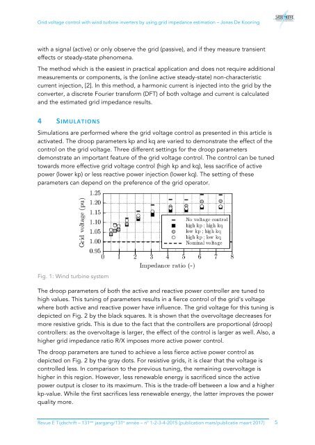
Fig. 1: Wind turbine system<br />
The droop parameters of both the active and reactive power controller are tuned to<br />
high values. This tuning of parameters results in a fierce control of the grid's voltage<br />
where both active and reactive power have influence. The grid voltage for this tuning is<br />
depicted on Fig. 2 by the black squares. It is shown that the overvoltage decreases for<br />
more resistive grids. This is due to the fact that the controllers are proportional (droop)<br />
controllers: as the overvoltage is larger, the effect of the control is larger as well. Also, a<br />
higher grid impedance ratio R/X imposes more active power control.<br />
The droop parameters are tuned to achieve a less fierce active power control as<br />
depicted on Fig. 2 by the gray dots. For resistive grids, it is clear that the voltage is<br />
controlled less. In comparison to the previous tuning, the remaining overvoltage is<br />
higher in this region. However, less renewable energy is sacrificed since the active<br />
power output is closer to its maximum. This is the trade-off between a low and a higher<br />
kp-value. While the first sacrifices less renewable energy, the latter improves the power<br />
quality more.<br />
Revue E Tijdschrift – 131 ste jaargang/131 e année – n° 1-2-3-4-<strong>2<strong>01</strong>5</strong> (publication mars/publicatie maart 2<strong>01</strong>7) 5