9. Schaltgerät - Kessel
9. Schaltgerät - Kessel 9. Schaltgerät - Kessel
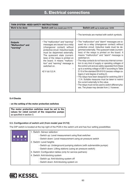
5. Electrical connectionsTWIN SYSTEM- HEED SAFETY INSTRUCTIONS!Work to be done Switch unit from model year 01/10 Switch unit up to model year 12/09• The terminals are marked with switch symbols.Outputs"Malfunction" and"warning"• The "malfunction" and "warning"messages are issued via a relay(changeover contact) withoutprotective circuit. Inductive loadsmust be dejammed externally.The quiescent state (currentless)of the relays is printed onthe board. It means "malfunction"and "warning" message isswitched on.•42 V dc/ 0,5 A• The "malfunction" and "alarm" messages are issuedvia a relay (changeover contact) withoutprotective circuit. Inductive loads must be dejammedexternally. The quiescent state (currentless)of the relays is printed on the board. Itmeans "malfunction" and "alarm" message isswitched on.• The relay contacts do not have any internal connectionto any kind of supply or operating voltages ofthe control unit and are safely separated from theseup to a working voltage of 300 V according to TableD.10 of the standard EN 61010 (excess voltage category2 and degree of soiling 2).• The relays have been designed for switching 230 V/ 2 A. Suitable measures must be taken to restrictthe current externally to this value.• The relays must not be used to switch different phases.The phase may deviate from L1 however.5.4 Checks- on the setting of the motor protection switchesThe motor protection switches must be set to thevalues for rated current of the respective pumpsas specified in section 3.5.5. Configuration of switch unit (from model year 01/10)The DIP switch is located at the top right of the PCB in the switch unit and has four setting possibilities1. Switch: Sensor selection- Switch up: Level measurement using float switcher- Switch down: Level measurement using air pressure switch2. Switch: Level heights- Switch up: Underground pumping stations (with submersible pumps)- Switch down: Lifting stations (using air pressure switch)3. Switch: Configuration tables (only for service partners)4. Switch: Anti-blocking system- Switch up: Anti-blocking system off- Switch down: Anti-blocking system on60
5.6 Configuration of switch unit (up to model year 12/09)5. Electrical connectionsConfiguration of the control is carried out in the factory using switches S601 ... S604 between the terminal blocks of the levelinputs and thermal protection input. For safety reasons, these must be checked according to the following descriptions.Pre-settings or reference settings are highlighted grey.- Basic setting is carried out using switch S604 (4-way DIP switches with 2 positions ON / OFF each).- Deviating settings are not allowed.up to year 12/09S604 / 1S604 / 2S604 / 3S604 / 4ONRun-time controlled System(wastewater lifting system)Submersible pumpwithout OFF level switchRotary field/phase monitoringonAnti-blocking functiononOFFLevel-controlled system(submersible pump system)Submersible pumpwith OFF level switchRotary field/phase failure monitoringoffAnti-blocking functionoff61
- Page 9 and 10: 4. Einbau und MontageIm Lieferumfan
- Page 13 and 14: 5. ElektroanschlussDie einzelnen An
- Page 15 and 16: 5. ElektroanschlussDOPPELANLAGE - S
- Page 17 and 18: 5.6 Konfiguration Schaltgerät (bis
- Page 19 and 20: 6. Inbetriebnahme6.4.1Bedienung Sch
- Page 21 and 22: 7. Inspektion und WartungAbb. 4 Abb
- Page 23 and 24: 8. Störungen und Abhilfemaßnahmen
- Page 25 and 26: 8. Störungen und Abhilfemaßnahmen
- Page 27 and 28: 8.2.2 Interne Überwachung8. Störu
- Page 29 and 30: 9. Schaltgerät9.1.2 Schaltplan Dop
- Page 31 and 32: 9. Schaltgerät9.2.2 Schaltplan Ein
- Page 33 and 34: 9. Schaltgerät9.3.2 Schaltplan Dop
- Page 35 and 36: 10. Ersatzteile und Zubehör10.2 Er
- Page 37 and 38: 10. Ersatzteile und Zubehör10.2.3
- Page 39 and 40: 10. Ersatzteile und Zubehör10.2.7
- Page 42 and 43: Übergabeprotokollnnn
- Page 44 and 45: ❑ Rückstauverschlüsse❑ Hebean
- Page 46 and 47: 1. Safety informationGeneral safety
- Page 48 and 49: Table of contents1. Safety informat
- Page 50 and 51: 3. Technical data3.1 Dimensions3.1.
- Page 52 and 53: 3. Technical data3.3 Electric switc
- Page 54 and 55: 4. Installation and assemblyA stand
- Page 56 and 57: 5. Electrical connectionsCAUTION:On
- Page 58 and 59: 5. Electrical connectionsSINGLE SYS
- Page 62 and 63: 6. Initial operation6.1 General ins
- Page 64 and 65: 7. Inspection and maintenanceThe sy
- Page 66 and 67: 8. Malfunctions and troubleshooting
- Page 68 and 69: 8. Malfunctions and troubleshooting
- Page 70 and 71: 8. Malfunctions and troubleshooting
- Page 72 and 73: 9. Control unit9.1 Switch unit (fro
- Page 74 and 75: 9. Control unit• The operating el
- Page 76 and 77: 9. Control unit9.3 Switch unit for
- Page 78 and 79: 10. Spare parts and accessories10.1
- Page 80 and 81: 10. Spare parts and accessories10.2
- Page 82 and 83: 10. Spare parts and accessories10.2
- Page 84: 11. Warranty1. In the case that a K
- Page 87 and 88: Important contacts / InfoSeparator
- Page 89 and 90: DIRECTIVES POUR L'INSTALLATION, LE
- Page 91 and 92: 1. Consignes de sécuritéDanger po
- Page 93 and 94: 2. Généralités2.1 Domaine d'empl
- Page 95 and 96: 3. Données techniques3.2 Pompes (A
- Page 97 and 98: 4. Installation et montageLes parti
- Page 99 and 100: 4. Installation et montageIMPORTANT
- Page 101 and 102: 5. Raccordement électriqueLes diff
- Page 103 and 104: 5. Raccordement électriqueINSTALLA
- Page 105 and 106: 5. Raccordement électrique5.6 Conf
- Page 107 and 108: 6. Mise en service6.4 Utilisation d
- Page 109 and 110: 7. Inspection et maintenanceTrou ta
5. Electrical connectionsTWIN SYSTEM- HEED SAFETY INSTRUCTIONS!Work to be done Switch unit from model year 01/10 Switch unit up to model year 12/09• The terminals are marked with switch symbols.Outputs"Malfunction" and"warning"• The "malfunction" and "warning"messages are issued via a relay(changeover contact) withoutprotective circuit. Inductive loadsmust be dejammed externally.The quiescent state (currentless)of the relays is printed onthe board. It means "malfunction"and "warning" message isswitched on.•42 V dc/ 0,5 A• The "malfunction" and "alarm" messages are issuedvia a relay (changeover contact) withoutprotective circuit. Inductive loads must be dejammedexternally. The quiescent state (currentless)of the relays is printed on the board. Itmeans "malfunction" and "alarm" message isswitched on.• The relay contacts do not have any internal connectionto any kind of supply or operating voltages ofthe control unit and are safely separated from theseup to a working voltage of 300 V according to TableD.10 of the standard EN 61010 (excess voltage category2 and degree of soiling 2).• The relays have been designed for switching 230 V/ 2 A. Suitable measures must be taken to restrictthe current externally to this value.• The relays must not be used to switch different phases.The phase may deviate from L1 however.5.4 Checks- on the setting of the motor protection switchesThe motor protection switches must be set to thevalues for rated current of the respective pumpsas specified in section 3.5.5. Configuration of switch unit (from model year 01/10)The DIP switch is located at the top right of the PCB in the switch unit and has four setting possibilities1. Switch: Sensor selection- Switch up: Level measurement using float switcher- Switch down: Level measurement using air pressure switch2. Switch: Level heights- Switch up: Underground pumping stations (with submersible pumps)- Switch down: Lifting stations (using air pressure switch)3. Switch: Configuration tables (only for service partners)4. Switch: Anti-blocking system- Switch up: Anti-blocking system off- Switch down: Anti-blocking system on60


