9. Schaltgerät - Kessel
9. Schaltgerät - Kessel
9. Schaltgerät - Kessel

You also want an ePaper? Increase the reach of your titles
YUMPU automatically turns print PDFs into web optimized ePapers that Google loves.
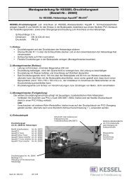
5. Electrical connectionsCAUTION:Only qualified electricians may carry out the work on electricalequipment described below. Before any work iscarried out on the switch unit, the pump or level control,the main switch and fuses must be switched off, i.e. be voltage-freeand secured against being switched back onagain5.1 General instructionsAn external main switch must be installed for the electricswitch unit that can be used in an emergency to switch off allthe downstream circuits independently of the control unit.This must be assigned clearly to the switch unit.All connected cables must be strain-relieved.Screw connections not used must always be sealed properly.IMPORTANT:All the cables connected to the electrical switch unit mustbe fixed in place using suitable measures (e.g. cable ties)so that they do not cause a hazard in the 1-error case, i.e.if a connection becomes loose..Please heed national and local safety regulations. If theseare not observed, personal hazard may be the result. In addition,no liability or warranty will be granted. After work hasbeen completed, the housing cover must be sealed properlyagain.5.3 Installation, wiringThe pump cables and control cable have a standard lengthof 5 m. Extension to max. 20 m is possible on site, but mustbe done using a VDE-conform connection.NOTE (applies to pressure diaphragm switches up to modelyear 01/10)The cable on the pressure level switch is a special cable withan air hose in the centre for compensating pressure for thepressure sensor in the lifting station to the atmosphere. Thefollowing must always be observed:– The cable may be cut off at any point but must never beextended. Special lengths of this cable can be ordered directlyfrom KESSEL.– The cable must be routed at a constant gradient from theswitch unit to the lifting station.For this reason, excess lengths must not be rolled up, thecable has to be shortened to fit.– The respective screw connection at the switch unit may betightened with a maximum torque of 2.5 Nm. Greater torquescan lead to the air hose being squeezed.– Deviations from these instructions can lead to functionalfailure of the pressure sensor and thus thewhole system!5.2 Mounting the switch unitScrew the housing cover with max. 1 Nm. Install the switchunit provided in a frost-free, dry, flood-proof and well-ventilatedroom. The switch unit has been designed for verticalwall-mounting on a solid base. Sufficient air circulation mustensure excessive inside temperatures develop. The unit ismounted using 4 screws (Ø 6 mm) at the corners of the housing(drilling template in the packaging box). The attachmentholes are accessible after the cover has been opened.56